EP1932016B1 - Method and device for controlling at least one object detection sensor - Google Patents
Method and device for controlling at least one object detection sensor Download PDFInfo
- Publication number
- EP1932016B1 EP1932016B1 EP06764331A EP06764331A EP1932016B1 EP 1932016 B1 EP1932016 B1 EP 1932016B1 EP 06764331 A EP06764331 A EP 06764331A EP 06764331 A EP06764331 A EP 06764331A EP 1932016 B1 EP1932016 B1 EP 1932016B1
- Authority
- EP
- European Patent Office
- Prior art keywords
- function
- sensor
- driver assistance
- coordinator
- operating mode
- Prior art date
- Legal status (The legal status is an assumption and is not a legal conclusion. Google has not performed a legal analysis and makes no representation as to the accuracy of the status listed.)
- Active
Links
- 238000001514 detection method Methods 0.000 title claims description 81
- 238000000034 method Methods 0.000 title claims description 22
- 230000006870 function Effects 0.000 claims description 176
- 238000011156 evaluation Methods 0.000 claims description 9
- 230000003044 adaptive effect Effects 0.000 claims description 8
- 230000001960 triggered effect Effects 0.000 claims description 2
- 230000000875 corresponding effect Effects 0.000 description 7
- 238000010586 diagram Methods 0.000 description 6
- 238000005259 measurement Methods 0.000 description 5
- 230000002596 correlated effect Effects 0.000 description 3
- 230000001276 controlling effect Effects 0.000 description 2
- 238000005315 distribution function Methods 0.000 description 2
- 230000003213 activating effect Effects 0.000 description 1
- 238000013459 approach Methods 0.000 description 1
- 230000001419 dependent effect Effects 0.000 description 1
- 238000011161 development Methods 0.000 description 1
- 230000018109 developmental process Effects 0.000 description 1
- 230000000694 effects Effects 0.000 description 1
- 230000002349 favourable effect Effects 0.000 description 1
- 238000009472 formulation Methods 0.000 description 1
- 239000000203 mixture Substances 0.000 description 1
Images
Classifications
-
- B—PERFORMING OPERATIONS; TRANSPORTING
- B60—VEHICLES IN GENERAL
- B60W—CONJOINT CONTROL OF VEHICLE SUB-UNITS OF DIFFERENT TYPE OR DIFFERENT FUNCTION; CONTROL SYSTEMS SPECIALLY ADAPTED FOR HYBRID VEHICLES; ROAD VEHICLE DRIVE CONTROL SYSTEMS FOR PURPOSES NOT RELATED TO THE CONTROL OF A PARTICULAR SUB-UNIT
- B60W30/00—Purposes of road vehicle drive control systems not related to the control of a particular sub-unit, e.g. of systems using conjoint control of vehicle sub-units
- B60W30/14—Adaptive cruise control
- B60W30/16—Control of distance between vehicles, e.g. keeping a distance to preceding vehicle
-
- G—PHYSICS
- G01—MEASURING; TESTING
- G01S—RADIO DIRECTION-FINDING; RADIO NAVIGATION; DETERMINING DISTANCE OR VELOCITY BY USE OF RADIO WAVES; LOCATING OR PRESENCE-DETECTING BY USE OF THE REFLECTION OR RERADIATION OF RADIO WAVES; ANALOGOUS ARRANGEMENTS USING OTHER WAVES
- G01S13/00—Systems using the reflection or reradiation of radio waves, e.g. radar systems; Analogous systems using reflection or reradiation of waves whose nature or wavelength is irrelevant or unspecified
- G01S13/88—Radar or analogous systems specially adapted for specific applications
- G01S13/93—Radar or analogous systems specially adapted for specific applications for anti-collision purposes
- G01S13/931—Radar or analogous systems specially adapted for specific applications for anti-collision purposes of land vehicles
- G01S2013/9314—Parking operations
-
- G—PHYSICS
- G01—MEASURING; TESTING
- G01S—RADIO DIRECTION-FINDING; RADIO NAVIGATION; DETERMINING DISTANCE OR VELOCITY BY USE OF RADIO WAVES; LOCATING OR PRESENCE-DETECTING BY USE OF THE REFLECTION OR RERADIATION OF RADIO WAVES; ANALOGOUS ARRANGEMENTS USING OTHER WAVES
- G01S13/00—Systems using the reflection or reradiation of radio waves, e.g. radar systems; Analogous systems using reflection or reradiation of waves whose nature or wavelength is irrelevant or unspecified
- G01S13/88—Radar or analogous systems specially adapted for specific applications
- G01S13/93—Radar or analogous systems specially adapted for specific applications for anti-collision purposes
- G01S13/931—Radar or analogous systems specially adapted for specific applications for anti-collision purposes of land vehicles
- G01S2013/93185—Controlling the brakes
-
- G—PHYSICS
- G01—MEASURING; TESTING
- G01S—RADIO DIRECTION-FINDING; RADIO NAVIGATION; DETERMINING DISTANCE OR VELOCITY BY USE OF RADIO WAVES; LOCATING OR PRESENCE-DETECTING BY USE OF THE REFLECTION OR RERADIATION OF RADIO WAVES; ANALOGOUS ARRANGEMENTS USING OTHER WAVES
- G01S13/00—Systems using the reflection or reradiation of radio waves, e.g. radar systems; Analogous systems using reflection or reradiation of waves whose nature or wavelength is irrelevant or unspecified
- G01S13/88—Radar or analogous systems specially adapted for specific applications
- G01S13/93—Radar or analogous systems specially adapted for specific applications for anti-collision purposes
- G01S13/931—Radar or analogous systems specially adapted for specific applications for anti-collision purposes of land vehicles
- G01S2013/9321—Velocity regulation, e.g. cruise control
-
- G—PHYSICS
- G01—MEASURING; TESTING
- G01S—RADIO DIRECTION-FINDING; RADIO NAVIGATION; DETERMINING DISTANCE OR VELOCITY BY USE OF RADIO WAVES; LOCATING OR PRESENCE-DETECTING BY USE OF THE REFLECTION OR RERADIATION OF RADIO WAVES; ANALOGOUS ARRANGEMENTS USING OTHER WAVES
- G01S13/00—Systems using the reflection or reradiation of radio waves, e.g. radar systems; Analogous systems using reflection or reradiation of waves whose nature or wavelength is irrelevant or unspecified
- G01S13/88—Radar or analogous systems specially adapted for specific applications
- G01S13/93—Radar or analogous systems specially adapted for specific applications for anti-collision purposes
- G01S13/931—Radar or analogous systems specially adapted for specific applications for anti-collision purposes of land vehicles
- G01S2013/9323—Alternative operation using light waves
-
- G—PHYSICS
- G01—MEASURING; TESTING
- G01S—RADIO DIRECTION-FINDING; RADIO NAVIGATION; DETERMINING DISTANCE OR VELOCITY BY USE OF RADIO WAVES; LOCATING OR PRESENCE-DETECTING BY USE OF THE REFLECTION OR RERADIATION OF RADIO WAVES; ANALOGOUS ARRANGEMENTS USING OTHER WAVES
- G01S13/00—Systems using the reflection or reradiation of radio waves, e.g. radar systems; Analogous systems using reflection or reradiation of waves whose nature or wavelength is irrelevant or unspecified
- G01S13/88—Radar or analogous systems specially adapted for specific applications
- G01S13/93—Radar or analogous systems specially adapted for specific applications for anti-collision purposes
- G01S13/931—Radar or analogous systems specially adapted for specific applications for anti-collision purposes of land vehicles
- G01S2013/9324—Alternative operation using ultrasonic waves
-
- G—PHYSICS
- G01—MEASURING; TESTING
- G01S—RADIO DIRECTION-FINDING; RADIO NAVIGATION; DETERMINING DISTANCE OR VELOCITY BY USE OF RADIO WAVES; LOCATING OR PRESENCE-DETECTING BY USE OF THE REFLECTION OR RERADIATION OF RADIO WAVES; ANALOGOUS ARRANGEMENTS USING OTHER WAVES
- G01S13/00—Systems using the reflection or reradiation of radio waves, e.g. radar systems; Analogous systems using reflection or reradiation of waves whose nature or wavelength is irrelevant or unspecified
- G01S13/88—Radar or analogous systems specially adapted for specific applications
- G01S13/93—Radar or analogous systems specially adapted for specific applications for anti-collision purposes
- G01S13/931—Radar or analogous systems specially adapted for specific applications for anti-collision purposes of land vehicles
- G01S2013/9325—Radar or analogous systems specially adapted for specific applications for anti-collision purposes of land vehicles for inter-vehicle distance regulation, e.g. navigating in platoons
Definitions
- the present invention relates to a method and a device for controlling at least one object detection sensor for a motor vehicle, wherein the at least one sensor is switchable between a plurality of operating modes, wherein a plurality of driver assistance functions for evaluating the objects detected by the object detection sensor can optionally access the at least one sensor and a Switching between the operating modes depending on the currently accessing assistance function is selected, and that between thejansauswerlungs wornen and the at least one sensor is provided a coordinator, each of the at least one sensor accessing driver assistance function the coordinator each an importance density function transmits, and that the at least one sensor for each activatable measurement mode, the coordinator transmits a detection probability density function to the coordinator and the coordinator for each, to the at least one Sensor access assistance function that selects the appropriate operating mode.
- From the DE 199 34 670 A1 is an object detection system, in particular for a motor vehicle, known, wherein the object detection system consists of a combination of at least three object detectors, each having a different detection range and / or a different Detekhonsreichweite. From the DE 101 47 443 A1 a method for controlling an object detection sensor for a motor vehicle is known, wherein the sensors are switchable between a plurality of operating modes.
- Automotive object detection systems often have a plurality of different sensor systems covering different detection ranges or have a sensor that can be operated in different operating modes with different detection ranges. Due to the growing number of driver assistance systems in the motor vehicle, the object data determined by the object detection sensors with respect to preceding vehicles and preceding stationary objects are used by different driver assistance radio stations, wherein these respective functions evaluate objects in different sensor detection areas. Such systems increase in complexity exponentially, since the functions and the sensors must each be coordinated with each other, so that the respective driver assistance functions process only the objects in the detection range of the sensor, which are necessary for their functionality and have to switch the object detection sensor in its operating modes ,
- the core of the present invention is to provide a method and a device which are configured so that an object detection sensor only has to know its different operating modes with the corresponding statistical distribution functions of the expected object detection positions and the corresponding driver assistance functions need only know the subregions of the sensor detection area. in which the objects are to be detected that are relevant to their respective functionality. According to the invention, this is achieved by providing a coordinator who, on the one hand, provides the areas in which statistical objects to be detected are to be expected by the object detection sensor and, on the other hand, informs the coordinator of the driver assistance functions in which sensor detection area parts are required for their functionality To detect objects.
- the coordinator in such a way that it correlates the respective distribution density functions with one another and thus determines the most suitable operating mode of the object detection sensor for each driver assistance function and correspondingly switches the object detection sensor between its operating modes in accordance with the currently activated driver assistance function.
- the importance density function indicates in which subarea of the sensor detection area for the respective function particularly relevant objects are to be evaluated by the function indicating the importance density as a function of the distance and / or the azimuth angle of the sensor detection area.
- importance density function w can either be one-dimensional in that only the distance of the detected objects is evaluated or a two-dimensional distribution function that evaluates both the distance and the azimuth angle of the detected object.
- the importance density function is thus defined as the attention request of the driver assistance function in a sensor-independent language.
- the importance density function indicates in which distance and / or in which azimuth angle ⁇ the objects to be detected are relevant for this particular driver assistance function.
- the detection probability density function is advantageous for specify in which subarea of the sensor detection area objects can be detected particularly well due to the selected operating mode, in that the function indicates the detection probability density as a function of the distance and / or the azimuth angle of the sensor detection area.
- the detection probability density function is thus defined to be the Indicates information of the sensor with respect to its different operating modes, depending on which operating mode, which sensor detection range is particularly covered or in which sensor detection range, a special resolution accuracy is present.
- the detection probability density function indicates where the respective operating mode can detect objects particularly well or in which sensor detection range statistically most objects are to be expected.
- the detection probability density function v can also be designed as a one-dimensional variable, which only evaluates the distance of the detected objects or, alternatively, as a two-dimensional variable, which takes into account both the distance d and the azimuth angle ⁇ of the detected objects.
- the integral sum is set equal to 1, or the detection probability density function v is integrated over the distance d and over the azimuth angle ⁇ , then the integral sum is set equal to 1, so that the detection probability density function is a dimensionless variable is to be correlated later with the importance density function w.
- the at least one object detection sensor is a plurality of sensors that are embodied in different types of sensors.
- the different sensor types are ultrasonic sensors, pulse radar sensors, frequency-modulated continuous wave (FMCW) radar sensors, lidar sensors and / or video sensors. It can also be provided that a sensor is designed so that it can be switched between a pulse radar mode and a frequency-modulated continuous wave mode, so that the different operating modes in this case would be the pulsed-radar mode as well as the frequency-modulated continuous-wave mode.
- FMCW frequency-modulated continuous wave
- the plurality of operating modes of the at least one sensor have different detection ranges and / or different types of modulation of the sensor and / or different resolution accuracies.
- the coordinator feeds the object data obtained by means of the at least one sensor to the driver assistance function for evaluation, as a function of which the corresponding operating mode has been selected.
- This functionality ensures that the coordinator feeds the currently determined object data to the driver assistance function, which has caused the sensor to switch over in the currently activated measurement mode.
- the selection of the operating mode of the at least one sensor to be activated by the coordinator is effected by correlation from the importance density function w with the detection probability density function v.
- additional assistance functions can be activated and, in addition to the active functions, access the at least one sensor without To configure the coordinator and / or the sensor with respect to the additional driver assistance function.
- the method according to the invention in the form of a control element which is provided for a control unit of a driver assistance function of a motor vehicle or for a control unit of a sensor of a motor vehicle.
- a program is stored on the control, which is executable on a computing device, in particular on a microprocessor or signal processor, and suitable for carrying out the method according to the invention.
- the invention is realized by a program stored on the control program, so that this provided with the program control in the same way is the invention as the method to whose execution the program is suitable.
- an electrical storage medium can be used as the control, for example a read-only memory.
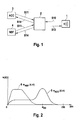
- FIG. 1 a schematic block diagram of the device according to the invention is shown.
- an object detection sensor 1 which may for example be designed as a radar sensor and has two operating modes, wherein a first operating mode A has a long range and a second operating mode B has a shorter range, but has a higher resolution accuracy and in shorter measuring cycles determines the Objekipositionen the detected objects, as the operating mode A.
- a coordinator 2 is shown, which combines the object detection sensor 1 with a plurality of driver assistance functions.
- driver assistance functions Two functions are listed by way of example as driver assistance functions, wherein the first driver assistance function 3 performs an ACC function on motorway-like highways or highways to control the speed of the own vehicle in the sense of a constant distance control behind a preceding vehicle identified as a target object.
- an automatically triggerable emergency brake function is shown, which determines whether a collision of the own vehicle with one of the detected objects is probable depending on the premeasible detected objects and, in the event that a collision is no longer avoidable, automatically triggered and carried out emergency braking.
- driver assistance functions 3, 4 which detect objects in the vehicle environment by means of environment detection sensors and driver assistance functions depending on the detected sensor data driver warnings or interventions in the drive train or the deceleration devices of the vehicle.
- the object detection sensor 1 is further capable of transmitting to the coordinator 2, as indicated by arrow S10, a detection probability density function v i (d, ⁇ ) for each possible operating mode which the object detection sensor 1 can activate.
- the driver assistance functions 3, 4 are also according to FIG Arrows S 11 capable of the coordinator 2 each an importance density function w i (d, ⁇ ) to transmit.
- the Coordinator 2 correlates each detection probability density function v i present to it with each present importance density function w i and, for each connected driver assistance function 3, 4, determines the combination with the greatest correlation result. Since the object detection sensor 1 is in most cases only operable in one operating mode at a time, the coordinator 2 informs the object detection sensor 1, represented by the arrow S13, which operating mode of the sensor 1 is most suitable for which driver assistance function 3, 4 Operating mode is most urgent. Thus, for example, shortly before an unavoidable collision, the operating mode is selected which is the most favorable for the emergency brake function (NBF), while in normal operation, for example, a continuous switching between operating modes is conceivable.
- NMF emergency brake function
- the object detection sensor 1 then sends the object data obtained in the respective operating modes to the coordinator 2, who forwards them to the corresponding driver assistance function 3 or 4 for further evaluation. It follows that additional driver assistance functions can be activated during operation without the sensor 1 having to be configured in advance for the respectively newly activated driver assistance function or without the sensor having to be configured to the detection area which is particularly relevant for this driver assistance function.
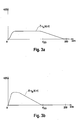
- importance density functions 5, 6 are plotted as a function of the distance d.
- the functions described in the exemplary embodiments are shown only as one-dimensional functions as a function of d, but these can also be readily implemented as multi-dimensional functions as a function of, for example, d and ⁇ .
- the driver assistance function 3 which is an ACC function, controls the vehicle speed on highways to preceding vehicles, which usually precede a certain following distance d ZO , so that the importance density function w ACC (d, ⁇ ) of the ACC function represented by the curve 5 , objects having their own vehicle at a distance greater than the target distance d ZO are of minor importance for the ACC function 3, so that the importance density function w ACC for distances d > d ZO approaches zero.
- Even before moving objects which have a shorter distance than the target distance d ZO (d ⁇ d ZO) for the distance control function is of secondary importance, as these occur very rarely in Autobähn cleanse and Although the speed control function has an effect, it does not correspond to the usual control situation.
- the importance density function w ACC has a small importance density for distances d ⁇ d ZO .
- the importance density function w ACC (d, ⁇ ) as represented by curve 5 is passed from the ACC function 3 to the coordinator 2 according to the arrow S11.
- a further importance density function w NBF (d, ⁇ ) is plotted, which is derived from the emergency brake function 4 according to the arrow S11 in FIG FIG. 1 to the coordinator 2.
- the purpose of the emergency brake function is to determine whether a collision with a vehicle in front is imminent in order to possibly trigger and carry out an automatic emergency braking.
- the importance density function w NBF (d, ⁇ ) is designed to have a high importance density at small distances d and to decrease with increasing distance d.
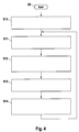
- FIGS. 3a and 3b For each operating mode of the object detection sensor 1, detection probability density functions v i (d, ⁇ ) are shown.
- the sensor 1 has a far-range mode A, which is characterized by its long range.
- a detection probability density function v A (d, ⁇ ) according to curve 7 is shown.
- This function shows in which distance ranges in the respective operating mode most likely to be expected objects to be detected.
- the detection probability density function v B (d, ⁇ ) is plotted according to curve 8, which, due to the near-range measurement mode B, is specially adapted to detect objects to be detected in the near range in front of the vehicle at small distances d.
- These two detection probability density functions v A and v B are detected by the object detection sensor 1 according to arrow S10 of FIG FIG. 1 forwarded to the coordinator 2.
- the coordinator 2 now carries out a correlation of all importance density functions w i and all of them transmitted in the detected detection probability density functions v i and determines for each driver assistance function 3, 4 one which is most suitable Measuring mode A, B.
- the correlations to be carried out by coordinator 2 are described in the following table.
- the coordinator 2 performs correlation of the importance density function W ACC (d, ⁇ ) with the detection probability density function V A (d, ⁇ ) according to the first row of the table. Since the curve 5 of FIG. 2 and the curve 7 of FIG. 3a , which are correlated with one another, have quantitatively coincident regions at equal distances, a correlation coefficient r [ACC; A] of, for example, 0.8.
- the importance density function W ACC with the detection probability density function v B is determined according to FIG. 3b correlates, for example, a correlation result r [ACC; B] of about 0.2, because there are d inequalities between the curves 5 and 8 at equal distances, resulting in a low correlation.
- the coordinator 2 according to the arrow S13 in FIG. 1 to the object detection sensor 1, which then selects measurements for the distance control function 3 the long range mode A and selects for object detections for the emergency brake function 4 for this purpose more suitable short-range mode B of the object detection sensor 1.
- the object values determined by the sensor 1 become the coordinator 2 passes on the measured values, depending on which in which operating mode A, B this was determined to the corresponding driver assistance functions 3, 4 passes for evaluation.
- FIG. 4 a schematic flow diagram of the inventive method is shown, which begins in step S9, for example, when activating a driver assistance function or when switching on the ignition of the vehicle.
- step S10 by the sensor 1 transmitting to the coordinator 2 a detection probability density function v i (d, ⁇ ) for each of the operating modes A, B that can be operated by it.
- each active driver assistance function 3, 4 in each case transmits an importance density function w i (d, ⁇ ) which, according to its functionality, is stored in the respective function evaluation device 3, 4.
- the coordinator 2 performs all possible correlations between detection probability density functions v i (d, ⁇ ) and importance density functions w i (d, ⁇ ) and determines for each active driver assistance function 3, 4 the operating mode A, B which gave the largest correlation coefficient , In the following step S 13, the coordinator 2 transmits to the sensor 1 for each activated driver assistance function 3, 4 the operating mode A, B for which the greatest correlation coefficient r has been established.
- step S14 it may be provided by way of example that the sensor 1 stores the most suitable operating mode A, B for each assistance function 3, 4 accessing it and the object data (d, ⁇ ) obtained in the respective deactivated operating mode A, B to the coordinator 2 outputs, which passes on these data according to the selected operating mode A, B to the corresponding assistance function 3, 4 for evaluation. Thereafter, the method is continued in step S11, so that again the active driver assistance functions 3, 4, the most appropriate operating modes A, B are assigned.
- This method and this device have the great advantage that new driver assistance functions can be activated at any time and if necessary several detection sensors can be connected to the coordinator 2.
- the driver assistance function is assigned to the operating mode of each possible object detection sensor 1 which is best suited for this purpose. For example, it can happen that a video sensor or a lidar sensor in heavy rain or is automatically deactivated in dense fog, as it can no longer provide reliable data. In this case, the sensor assistance functions dependent on this sensor are no longer supplied with object data by the video sensor but by the operating mode of an object detection sensor 1 which is still in operation despite the poor visibility conditions. It is also possible to automatically switch on or off driver assistance systems at any time without the need for a new sensor configuration.
Landscapes
- Engineering & Computer Science (AREA)
- Radar, Positioning & Navigation (AREA)
- Remote Sensing (AREA)
- Physics & Mathematics (AREA)
- Automation & Control Theory (AREA)
- Transportation (AREA)
- Mechanical Engineering (AREA)
- Electromagnetism (AREA)
- Computer Networks & Wireless Communication (AREA)
- General Physics & Mathematics (AREA)
- Traffic Control Systems (AREA)
- Regulating Braking Force (AREA)
Description
Die vorliegende Erfindung betrifft ein Verfahren und eine Vorrichtung zur Steuerung mindestens eines Objektdetektionssensors für ein Kraftfahrzeug, wobei der mindestens eine Sensor zwischen mehreren Betriebsmodi umschaltbar ist, wobei mehrere Fahrerassistenzfunktionen zur Auswertung der mittels des Objektdetektionssensors detektierten Objekte wahlfrei auf den mindestens einen Sensor zugreifen können und eine Umschaltung zwischen den Betriebsmodi in Abhängigkeit der momentan zugreifenden Assistenzfunktion ausgewählt wird, und dass zwischen den Funktionsauswerlungseinrichtungen und dem mindestens einen Sensor ein Koordinator vorgesehen ist, der jede auf den mindestens einen Sensor zugreifende Fahrerassistenzfunktion dem Koordinator jeweils eine Wichtigkeitsdichtefunktion übermittelt, und dass der mindestens eine Sensor für jeden aktivierbaren Messmodus dem Koordinator eine Detektionswahrscheinlichkeitsdichtefunktion übermittelt und der Koordinator für jede, auf den mindestens einen Sensor zugreifende Assistenzfunktion, den geeigneten Betriebsmodus auswählt.The present invention relates to a method and a device for controlling at least one object detection sensor for a motor vehicle, wherein the at least one sensor is switchable between a plurality of operating modes, wherein a plurality of driver assistance functions for evaluating the objects detected by the object detection sensor can optionally access the at least one sensor and a Switching between the operating modes depending on the currently accessing assistance function is selected, and that between the Funktionsauswerlungseinrichtungen and the at least one sensor is provided a coordinator, each of the at least one sensor accessing driver assistance function the coordinator each an importance density function transmits, and that the at least one sensor for each activatable measurement mode, the coordinator transmits a detection probability density function to the coordinator and the coordinator for each, to the at least one Sensor access assistance function that selects the appropriate operating mode.
Aus der
Objektdetektionssysteme für Kraftfahrzeuge weisen häufig eine Mehrzahl unterschiedlicher Sensorsysteme auf, die unterschiedliche Erfassungsbereiche abdecken, oder weisen einen Sensor auf, der in verschiedenen Betriebsmodi mit unterschiedlichen Erfassungsbereichen betrieben werden kann. Durch die wachsende Anzahl an Fahrerassistenzsystemen im Kraftfahrzeug werden die von den Objektdetektionssensoren ermittelten Objektdaten bezüglich vorherfahrender Fahrzeuge und vorausbefindlicher stehender Objekte von unterschiedlichen Fahrerassistenzfunküonen benützt, wobei diese jeweiligen Funktionen Objekte in unterschiedlichen Sensorerfassungsbereichen auswerten. Derartige Systeme nehmen in ihrer Komplexität exponentiell zu, da die Funktionen und die Sensoren jeweils aufeinander abgestimmt werden müssen, so dass die jeweiligen Fahrerassistenzfunktionen nur die Objekte im Erfassungsbereich des Sensors verarbeiten, die für ihre Funktionalität notwendig sind und dabei den Objektdetektionssensor in seinen Betriebsmoden umschalten müssen.Automotive object detection systems often have a plurality of different sensor systems covering different detection ranges or have a sensor that can be operated in different operating modes with different detection ranges. Due to the growing number of driver assistance systems in the motor vehicle, the object data determined by the object detection sensors with respect to preceding vehicles and preceding stationary objects are used by different driver assistance radio stations, wherein these respective functions evaluate objects in different sensor detection areas. Such systems increase in complexity exponentially, since the functions and the sensors must each be coordinated with each other, so that the respective driver assistance functions process only the objects in the detection range of the sensor, which are necessary for their functionality and have to switch the object detection sensor in its operating modes ,
Der Kern der vorliegenden Erfindung ist es, ein Verfahren und eine Vorrichtung anzugeben, die so ausgestaltet sind, dass ein Objektdetektionssensor lediglich seine unterschiedlichen Betriebsmodi kennen muss mit den entsprechenden statistischen Verteilungsfunktionen der zu erwartenden Objektdetektionspositionen sowie die entsprechende Fahrerassistenzfunktionen lediglich die Teilbereiche des Sensorerfassungsbereichs kennen müssen, in denen die Objekte zu detektieren sind, die für ihre jeweilige Funktionalität relevant sind. Erfindungsgemäß wird dieses gelöst, indem ein Koordinator vorgesehen ist, der einerseits vom Objektdetektionssensor für seine jeweiligen Betriebsmodi die Bereiche zu Verfügung stellt, in denen statistisch zu detektierende Objekte zu erwarten sind und andererseits die Fahrerassistenzfunktionen dem Koordinator mitteilen, in welchem Sensorerfassungsbereichsteilen die für ihre Funktionalität erforderlichen Objekte zu detektieren sind. Dieses kann vom Koordinator derart gelöst werden, dass dieser die jeweiligen Verteilungsdichtefunktionen miteinander korreliert und somit für jede Fahrerassistenzfunktion den geeignetsten Betriebsmodus des Objektdetektionssensors bestimmt und entsprechend der momentan aktivierten Fahrerassistenzfunktion den Objektdetektionssensor entsprechend zwischen seinem Betriebsmodi umschaltet.The core of the present invention is to provide a method and a device which are configured so that an object detection sensor only has to know its different operating modes with the corresponding statistical distribution functions of the expected object detection positions and the corresponding driver assistance functions need only know the subregions of the sensor detection area. in which the objects are to be detected that are relevant to their respective functionality. According to the invention, this is achieved by providing a coordinator who, on the one hand, provides the areas in which statistical objects to be detected are to be expected by the object detection sensor and, on the other hand, informs the coordinator of the driver assistance functions in which sensor detection area parts are required for their functionality To detect objects. This can be solved by the coordinator in such a way that it correlates the respective distribution density functions with one another and thus determines the most suitable operating mode of the object detection sensor for each driver assistance function and correspondingly switches the object detection sensor between its operating modes in accordance with the currently activated driver assistance function.
Erfindungsgemäß wird dieses durch die Merkmale der unabhängigen Ansprüche gelöst. Vorteilhafte Weiterbildungen und Ausgestaltungen ergeben sich aus den Unteransprüchen.According to the invention this is achieved by the features of the independent claims. Advantageous developments and refinements emerge from the subclaims.
Vorteilhafterweise gibt die Wichtigkeitsdichtefunktion an, in welchem Teilbereich des Sensorerfassungsbereichs für die jeweilige Funktion besonders relevante Objekte auszuwerten sind, indem die Funktion die Wichtigkeitsdichte in Abhängigkeit des Abstands und/oder des Azimutwinkels des Sensorerfassungsbereichs angibt. Hierbei kann dich Wichtigkeitsdichtefunktion w entweder eindimensional sein, indem lediglich der Abstand der detektierten Objekte ausgewertet wird oder eine zweidimensionale Verteilungsfunktion sein, die sowohl den Abstand als auch den Azimutwinkel des detektierten Objektes auswertet. Die Wichtigkeitsdichtefunktion ist damit definiert als die Aufmerksamkeitsanforderung der Fahrerassistenzfunktion in einer sensorunabhängigen Sprache. In anderen Worten gibt die Wichtigkeitsdichtefunktion an, in welchem Abstand und/oder in welchem Azimutwinkel ϕ sich die zu detektierenden Objekte aufhalten, die für diese spezielle Fahrerassistenzfunktion relevant sind Beispielsweise ist es bei einer automatischen Notbremsfunktion wichtig, besonders die Objekte zu erkennen, die im nahen Fahrzeugumfeld vorhanden sind, um eventuell eine Kollisionsgefahr erkennen zu können. Weiter entfernte Objekte, auf die der Fahrer oder eine Fahrerassistenzfunktion noch rechtzeitig reagieren kann sind für biespeilhaft betrachtete Notbremsfunktion unrelevant. Vorteilhafterweise ist die Wichtigkeitsdichtefunktion in Anlehnung an statistische Verteilungsdichtefunktionen so normiert, dass 
Weiterhin ist es vorteilhaft, dass die Detektionswahrscheinlichkeitsdichtefunktion angibt, in welchem Teilbereich des Sensorerfassungsbereichs Objekte aufgrund des ausgewählten Betriebsmoduses besonders gut detektierbar sind, indem die Funktion die Detektionswahrscheinlichkeitsdichte in Abhängigkeit des Abstands und/ oder des Azimutwinkels des Sensorerfassungsbereichs angibt. Die Detektionswahrscheinlichkeitsdichtefunktion ist demnach so definiert, dass diese die Information des Sensors bezüglich seiner unterschiedlichen Betriebsmodi angibt, je nachdem in welcher Betriebsart welcher Sensorerfassungsbereich besonders abgedeckt wird oder in welchem Sensorerfassungsbereich eine besondere Auflösungsgenauigkeit vorhanden ist. In anderen Worten gibt die Detektionswahrscheinlichkeitsdichtefunktion an, wo der jeweilige Betriebsmodus besonders gut Objekte erkennen kann bzw. in welchem Sensorerfassungsbereich statistisch die meisten Objekte zu erwarten sind. Auch die Detektionswahrscheinlichkeitsdichtefunktion v kann wahlweise als eindimensionale Größe ausgeführt sein, die lediglich den Abstand der erkannten Objekte auswertet oder alternativ als zweidimensionale Größe ausgerührt sein, die sowohl den Abstand d als auch den Azimutwinkel ϕ der erkannten Objekte berücksichtigt. Auch die Detektionswahrscheinlichkeitsdichtefunktion ist in Anlehnung an statistische Verteilungsdichtefunktionen so normiert, dass 
Weiterhin ist es vorteilhaft dass der mindestens eine Objektdetektionssensor mehrere Sensoren sind, die in unterschiedlichen Sensorarten ausgeführt sind.Furthermore, it is advantageous for the at least one object detection sensor to be a plurality of sensors that are embodied in different types of sensors.
Weiterhin ist es vorteilhaft, dass die unterschiedlichen Sensorarten Ultraschallsensoren, Pulsradarsensoren, frequenzmodulierte Dauerstrich (FMCW)-Radarsensoren, Lidarsensoren und/ oder Videosensoren sind. Es kann auch vorgesehen sein, dass ein Sensor so ausgeführt ist, dass er zwischen einem Pulsradarbetrieb und einem frequenzmodulierten Dauerstrichbetrieb umgeschaltet werden kann, sodass die unterschiedlichen Betriebsmodi in diesem Fall der Pulsradarmodus sowie der frequenzmodulierte Dauerstrichmodus wären.Furthermore, it is advantageous that the different sensor types are ultrasonic sensors, pulse radar sensors, frequency-modulated continuous wave (FMCW) radar sensors, lidar sensors and / or video sensors. It can also be provided that a sensor is designed so that it can be switched between a pulse radar mode and a frequency-modulated continuous wave mode, so that the different operating modes in this case would be the pulsed-radar mode as well as the frequency-modulated continuous-wave mode.
Vorteilhafterweise weisen die mehreren Betriebsmodi des mindestens einen Sensors unterschiedliche Erfassungsbereiche und/oder unterschiedliche Modulationsarten des Sensors und/oder unterschiedliche Auflösungsgenauigkeiten auf.Advantageously, the plurality of operating modes of the at least one sensor have different detection ranges and / or different types of modulation of the sensor and / or different resolution accuracies.
Besonders vorteilhaft ist es, dass die mehreren Funktionen eine oder eine beliebige Kombination der nachfolgend aufgeführten Fahrerassistenzfunktionen sind. Als mögliche Fahrerassistenzfunktionen sind
- eine adaptive Abstands- und Geschwindigkeitsregelfunktion für autobahnähnlich ausgebaute Landstraßen und Autobahnen, auch als LangRange-Adaptive-Cruise-Control (LR-ACC) bezeichnet,
- eine Stop & Go-fähige, adaptive Abstands- und Geschwindigkeitsregelfunktion für den Stadtverkehr, die auch als ShortRange-Adaptive-Cruise-Control (SR-ACC) bezeichnet wird,
- eine automatisch auslösende Notbremsfunktion (NBF), die eine unmittelbar bevorstehende Kollision des eigenen Fahrzeugs mit einem weiteren Fahrzeug vermeiden oder in ihrer Stärke mindern soll,
- eine Funktion, die eine Kollisionssituation erkennt und den Fahrer warnt oder die Auslöseschwelle eines Bremsassistenten verändert,
- eine Spurhaltefunktion,
- eine Spurverlassenswarnungsfunktion und/oder
- eine Einparkhilfe
- an adaptive distance and speed control function for highway-like highways and freeways, also known as Long Range Adaptive Cruise Control (LR-ACC),
- a stop-and-go, adaptive distance and cruise control function for urban traffic, also known as Short Range Adaptive Cruise Control (SR-ACC),
- an automatically triggering emergency brake function (NBF), which should avoid an imminent collision of one's own vehicle with another vehicle or reduce its strength,
- a feature that detects a collision situation and warns the driver or alters the triggering threshold of a Brake Assist,
- a lane keeping function,
- a lane departure warning function and / or
- a parking aid
Weiterhin ist es vorteilhaft, dass der Koordinator die mittels des wenigstens einen Sensors gewonnenen Objektdaten der Fahrerassistenzfunktion zur Auswertung zuführt, in deren Abhängigkeit der entsprechende Betriebsmodus gewählt wurde. Diese Funktionalität stellt sicher, dass der Koordinator der Fahrerassistenzfunktion die momentan ermittelten Objektdaten zuführt, die den Sensor veranlasst hat, in dem gerade aktivierten Messmodus umzuschalten.Furthermore, it is advantageous that the coordinator feeds the object data obtained by means of the at least one sensor to the driver assistance function for evaluation, as a function of which the corresponding operating mode has been selected. This functionality ensures that the coordinator feeds the currently determined object data to the driver assistance function, which has caused the sensor to switch over in the currently activated measurement mode.
Weiterhin ist es vorteilhaft, dass die Auswahl des zu aktivierenden Betriebsmoduses des wenigstens einen Sensors durch den Koordinator durch Korrelation aus der Wichtigkeitsdichtefunktion w mit der Detektionswahrscheinlichkeitsdichtefunktion v erfolgt.Furthermore, it is advantageous that the selection of the operating mode of the at least one sensor to be activated by the coordinator is effected by correlation from the importance density function w with the detection probability density function v.
Weiterhin ist es vorteilhaft das zusätzliche Assistenzfunktionen aktivierbar sind und neben den aktiven Funktionen auf den wenigstens einen Sensor zugreifen können, ohne den Koordinator und/oder den Sensor bezüglich der zusätzlichen Fahrerasssistenzfunktion konfigurieren zu müssen.Furthermore, it is advantageous that additional assistance functions can be activated and, in addition to the active functions, access the at least one sensor without To configure the coordinator and / or the sensor with respect to the additional driver assistance function.
Weiterhin ist es vorteilhaft, dass im Koordinator eine Einrichtung zur Korrelationsauswertung vorgesehen ist.Furthermore, it is advantageous that a means for correlation evaluation is provided in the coordinator.
Von besonderer Bedeutung ist die Realisierung des erfindungsgemäßen Verfahrens in Form eines Steuerelements, das für ein Steuergerät einer Fahrerassistenzfunktion eines Kraftfahrzeugs oder für ein Steuergerät eines Sensors eines Kraftfahrzeugs vorgesehen ist. Dabei ist auf dem Steuerelement eine Programm gespeichert, das auf einem Rechengerät, insbesondere auf einem Mikroprozessor oder Signalprozessor, ablauffähig und zur Ausführung des erfindungsgemäßen Verfahrens geeignet ist. In diesem Fall wird also die Erfindung durch ein auf dem Steuerelement abgespeichertes Programm realisiert, so dass dieses mit dem Programm versehene Steuerelement in gleicher Weise die Erfindung darstellt wie das Verfahren, zu dessen Ausführung das Programm geeignet ist. Als Steuerelement kann insbesondere ein elektrisches Speichermedium zur Anwendung kommen, beispielsweise ein Read-Only-Memory.Of particular importance is the realization of the method according to the invention in the form of a control element which is provided for a control unit of a driver assistance function of a motor vehicle or for a control unit of a sensor of a motor vehicle. In this case, a program is stored on the control, which is executable on a computing device, in particular on a microprocessor or signal processor, and suitable for carrying out the method according to the invention. In this case, therefore, the invention is realized by a program stored on the control program, so that this provided with the program control in the same way is the invention as the method to whose execution the program is suitable. In particular, an electrical storage medium can be used as the control, for example a read-only memory.
Weitere Merkmale, Anwendungsmöglichkeiten und Vorteile der Erfindung ergeben sich aus der nachfolgenden Beschreibung von Ausführungsbeispielen der Erfindung, die in den Figuren der Zeichnung dargestellt sind. Dabei bilden alle beschriebenen oder dargestellten Merkmale für sich oder in beliebiger Kombination den Gegenstand der Erfindung, unabhängig von ihrer Zusammenfassung in den Patentansprüchen oder deren Rückbeziehung sowie unabhängig von ihrer Formulierung bzw. Darstellung in der Beschreibung bzw. in den Zeichnungen.Other features, applications and advantages of the invention will become apparent from the following description of embodiments of the invention, which are illustrated in the figures of the drawing. All described or illustrated features, alone or in any combination form the subject of the invention, regardless of their combination in the claims or their dependency and regardless of their formulation or representation in the description or in the drawings.
Nachfolgend werden Ausführungsbeispiele der Erfindung anhand der Zeichnung erläutert. Es zeigen
- Figur 1
- ein schematisches Blockschaltbild eine Ausführungsform der erfindungsgemäßen Vorrichtung,
Figur 2- ein Wichtigkeitsdichtefunktionsdiagramm einer ersten und einer zweiten Fahrerassistenzfunktion,
- Figur 3a, 3b
- jeweils ein Detektionswahrscheinlichkeitsdichtefunktionsdiagramm eines ersten und eines zweiten Betriebsmoduses des Sensors und
- Figur 4
- ein Ablaufdiagramm eine Ausführungsform des erfindungsgemäßen Verfahrens.
- FIG. 1
- a schematic block diagram of an embodiment of the device according to the invention,
- FIG. 2
- an importance density function diagram of a first and a second driver assistance function,
- Figure 3a, 3b
- each a detection probability density function diagram of a first and a second operating mode of the sensor and
- FIG. 4
- a flow diagram of an embodiment of the method according to the invention.
In
In
In den
Der Koordinator 2 führt nun eine Korrelation aller ihm übermittelten Wichtigkeitsdichtefunktionen wi und aller im übermittelten Detekdonswahrscheinlichkeitsdichtefunktionen vi durch und ermittelt für jede Fahrerassistenzfunktion 3, 4 einen am ehesten geeigneten Messmodus A, B. Die vom Koordinator 2 durchzuführenden Korrelationen sind besipielshaft in nachfolgender Tabelle aufgetragen.
vA(d,ϕ)
vB(d,ϕ)
v A (d, φ)
v B (d, φ)
Der Koordinator 2 führt gemäß der ersten Zeile der Tabelle eine Korrelation der Wichtigkeitsdichtefunktion WACC(d,ϕ) mit der Detektionswahrscheinlichkeitsdichtefunktion VA(d,ϕ) durch. Da die Kurve 5 der
In
Dieses Verfahren und diese Einrichtung haben den großen Vorteil, dass jederzeit neue Fahrerassistenzfunktionen aktiviert werden können und gegebenenfalls mehrere Detektionssensoren an den Koordinator 2 angeschlossen sein können. Je nach dem welche Objektdetektionssensoren 1 momentan aktiv sind bzw. welche Betriebsmodi aktiv sind, wird die Fahrerassistenzfunktion dem Betriebsmodus eines jeden möglichen Objektdetektionssensors 1 zugeordnet der hierfür am besten geeignet ist. Beispielweise kann es vorkommen, dass ein Videosensor oder ein Lidarsensor bei starkem Regen oder bei dichtem Nebel automatisch deaktiviert wird, da er keine verlässlichen Daten mehr liefern kann. In diesem Fall werden die von diesem Sensor abhängigen Fahrerassistenzfunktionen nicht mehr durch den Videosensor mit Objektdaten beliefert sondern von dem Betriebsmodus eines Objektdetektionssensors 1, der trotz der schlechten Sichtverhältnisse noch in Betrieb ist. Auch ist es möglich Fahrerassistenzsystemen jederzeit automatisch zu oder abzuschalten ohne dass hierfür eine neue Sensorkonfiguration benötigt wird.This method and this device have the great advantage that new driver assistance functions can be activated at any time and if necessary several detection sensors can be connected to the
Claims (12)
- Method for controlling at least one object detection sensor (1) for a motor vehicle, wherein the at least one sensor (1) can be switched over between a plurality of operating modes (7, 8), wherein a plurality of driver assistance functions (3, 4) for evaluating the objects which are detected by means of the object detection sensor (1) can randomly access the at least one sensor (1), and switching over between the operating modes (7, 8) is selected as a function of the driver assistance function (3, 4) which is accessing at a particular time, characterized
in that a coordinator (2) is provided between the function evaluation devices (3, 4) and the at least one sensor (1),
in that each driver assistance function (3, 4) which accesses the at least one sensor (1) transmits in each case a weighting density function (wi(d, ϕ)) to the coordinator, and in that the at least one sensor (1) transmits a detection probability density function (vi(d, ϕ)) to the coordinator (2) for each operating mode (7, 8) which can be activated, and the coordinator (2) selects the most suitable operating mode (7, 8) for each driver assistance function (3, 4) which accesses the at least one sensor (1). - Method according to Claim 1, characterized in that the weighting density function (wi(d, ϕ)) specifies the part of the sensor-sensing region in which objects which are particularly relevant for the respective driver assistance function (3, 4) are to be evaluated
in that the driver assistance function specifies the weighting density as a function of the distance (d) and/or the azimuth angle (ϕ) of the sensor-sensing region. - Method according to Claim 1 or 2, characterized in that the detection probability density function (vi(d, ϕ)) specifies the part of the sensor-sensing region in which objects can be particularly well detected on the basis of the selected operating mode (7, 8) in that the driver assistance function (3, 4) specifies the detection probability density as a function of the distance (d) and/or the azimuth angle (ϕ) of the sensor-sensing region.
- Method according to one of the preceding claims, characterized in that the at least one object detection sensor (1) comprises a plurality of sensors which are embodied as different types of sensor.
- Method according to Claim 4, characterized in that the different types of sensor are ultrasonic sensors, pulse radar sensors, frequency-modulated continuous wave (FMCW) radar sensors, Lidar sensors and/or video sensors.
- Method according to one of the preceding claims, characterized in that the plurality of operating modes (7, 8) of the at least one sensor (1) have different sensing regions and/or different types of modulation of the sensor and/or different resolution accuracy levels.
- Method according to one of the preceding claims, characterized in that the plurality of driver assistance functions (3, 4) are- an adaptive distance and speed control function for upgraded highways and motorways (LR-ACC) and/or- a stop & go-enabled, adaptive distance and speed control function for urban traffic (SR-ACC) and/or- an automatically triggered emergency braking function (NBF) and/or- a function which detects a collision situation and warns the driver or changes the triggering threshold of a braking assistance and/or- a lane keeping function (LKS) and/or- a lane departure warning function (LDW), and/or- a parking assistant (EPH).
- Method according to one of the preceding claims, characterized in that the object data (d, ϕ), which have been acquired by means of the at least one sensor (1) and as a function of which the corresponding operating mode (7, 8) has been selected, are fed by the coordinator (2) to the driver assistance function (3, 4) for evaluation.
- Method according to one of the preceding claims, characterized in that the operating mode (7, 8) to be activated, of the at least one sensor (1) is selected by means of the coordinator (2) through correlation of the weighting density function (wi(d, ϕ)) with the detection probability density function (vi(d, ϕ) ) .
- Method according to one of the preceding claims, characterized in that additional driver assistance functions can be activated and can access the at least one sensor (1), in addition to the active functions, without the coordinator (2) and/or the sensor (1) having to be re-configured for the additional driver assistance function.
- Device for controlling at least one object detection sensor (1) for a motor vehicle, wherein the at least one sensor (1) can be switched over between a plurality of operating modes (7, 8), wherein a plurality of driver assistance functions (3, 4) for evaluating the objects which are detected by means of the object detection sensor (1) can randomly access the at least one sensor (1), and switching over between the operating modes (7, 8) is selected as a function of the driver assistance function (3, 4) which is accessing at a particular time, characterized
in that a coordinator (2) is provided between the function evaluation devices (3, 4) and the at least one sensor (1) ,
in that each driver assistance function (3, 4) which accesses the at least one sensor (1) transmits in each case a weighting density function (wi(d, ϕ)) to the coordinator, and in that the at least one sensor (1) transmits a detection probability density function (vi(d, ϕ)) to the coordinator (2) for each operating mode (7, 8) which can be activated, and the coordinator (2) selects the most suitable operating mode (7, 8) for each driver assistance function (3, 4) which accesses the at least one sensor (1). - Device according to Claim 11, characterized in that a correlation-evaluating apparatus is provided in the coordinator (2).
Applications Claiming Priority (2)
| Application Number | Priority Date | Filing Date | Title |
|---|---|---|---|
| DE102005046045A DE102005046045A1 (en) | 2005-09-27 | 2005-09-27 | Object detection sensor controlling method for motor vehicle, involves transmitting important and detection probability density functions to coordinator, and selecting suitable operating mode for driver assistance function by coordinator |
| PCT/EP2006/065298 WO2007036390A1 (en) | 2005-09-27 | 2006-08-15 | Method and device for controlling at least one object detection sensor |
Publications (2)
| Publication Number | Publication Date |
|---|---|
| EP1932016A1 EP1932016A1 (en) | 2008-06-18 |
| EP1932016B1 true EP1932016B1 (en) | 2009-04-15 |
Family
ID=37114350
Family Applications (1)
| Application Number | Title | Priority Date | Filing Date |
|---|---|---|---|
| EP06764331A Active EP1932016B1 (en) | 2005-09-27 | 2006-08-15 | Method and device for controlling at least one object detection sensor |
Country Status (6)
| Country | Link |
|---|---|
| US (1) | US7991526B2 (en) |
| EP (1) | EP1932016B1 (en) |
| JP (1) | JP4718612B2 (en) |
| CN (1) | CN101273280A (en) |
| DE (2) | DE102005046045A1 (en) |
| WO (1) | WO2007036390A1 (en) |
Families Citing this family (27)
| Publication number | Priority date | Publication date | Assignee | Title |
|---|---|---|---|---|
| DE102007036787A1 (en) * | 2007-08-03 | 2009-02-05 | Robert Bosch Gmbh | Distance controller with automatic stop function |
| JP5634046B2 (en) * | 2009-09-25 | 2014-12-03 | クラリオン株式会社 | Sensor controller, navigation device, and sensor control method |
| EP2306433A1 (en) * | 2009-10-05 | 2011-04-06 | Nederlandse Organisatie voor toegepast -natuurwetenschappelijk onderzoek TNO | Collision avoidance system and method for a road vehicle and respective computer program product |
| DE102010023540A1 (en) * | 2010-06-11 | 2011-12-15 | Audi Ag | Method for controlling the operation of at least one sensor system encompassing the surroundings and motor vehicle |
| FR2964632B1 (en) * | 2010-09-09 | 2012-10-19 | Peugeot Citroen Automobiles Sa | METHOD FOR MANAGING A DRIVER ASSISTANCE SYSTEM COUPLED TO A BRAKE ASSISTING SYSTEM OF A MOTOR VEHICLE CONFRONTED WITH A RISK OF COLLISION |
| DE102011102557A1 (en) * | 2011-05-26 | 2012-11-29 | Valeo Schalter Und Sensoren Gmbh | Driver assistance device with a plurality of ultrasonic sensors and vehicle with such a driver assistance device and method for operating a driver assistance device |
| WO2013021490A1 (en) * | 2011-08-10 | 2013-02-14 | トヨタ自動車株式会社 | Driving assistance device |
| JP5754509B2 (en) * | 2011-08-10 | 2015-07-29 | トヨタ自動車株式会社 | Driving assistance device |
| US8706458B2 (en) * | 2011-10-05 | 2014-04-22 | International Business Machines Corporation | Traffic sensor management |
| JP5522157B2 (en) * | 2011-12-14 | 2014-06-18 | 株式会社デンソー | Preceding vehicle determination device and inter-vehicle distance control device |
| JP5981237B2 (en) * | 2012-06-15 | 2016-08-31 | トヨタ自動車株式会社 | Driving assistance device |
| KR20150061752A (en) * | 2013-11-28 | 2015-06-05 | 현대모비스 주식회사 | Device for driving assist and method for activating the function automatically by the device |
| DE102014009869A1 (en) * | 2014-07-03 | 2016-01-21 | Audi Ag | Method for operating a radar sensor in a motor vehicle and motor vehicle |
| DE102015205608A1 (en) | 2015-03-27 | 2016-09-29 | Siemens Aktiengesellschaft | Method for operating vehicles and device for a vehicle |
| JP6465055B2 (en) * | 2015-05-19 | 2019-02-06 | 株式会社デンソー | Collision avoidance support device and collision avoidance support method |
| US10502826B2 (en) * | 2015-06-17 | 2019-12-10 | Novelic D.O.O. | Millimeter-wave sensor system for parking assistance |
| EP3195076B1 (en) | 2015-06-26 | 2021-01-20 | SZ DJI Technology Co., Ltd. | System and method for selecting an operation mode of a mobile platform |
| US11003922B2 (en) | 2016-04-20 | 2021-05-11 | Mitsubishi Electric Corporation | Peripheral recognition device, peripheral recognition method, and computer readable medium |
| US9855894B1 (en) * | 2016-09-16 | 2018-01-02 | Volkswagen Aktiengesellschaft | Apparatus, system and methods for providing real-time sensor feedback and graphically translating sensor confidence data |
| US11318842B2 (en) * | 2016-12-27 | 2022-05-03 | Nec Corporation | First train-installed device, method, and recording medium |
| US10114375B1 (en) * | 2017-04-06 | 2018-10-30 | Delphi Technologies, Inc. | Motion-characteristic based object classification for automated vehicle |
| DE102017210045A1 (en) * | 2017-06-14 | 2018-12-20 | Robert Bosch Gmbh | Sensor device for an automated vehicle |
| DE102018200618A1 (en) * | 2018-01-16 | 2019-07-18 | Robert Bosch Gmbh | sensor device |
| JP6643390B2 (en) * | 2018-04-19 | 2020-02-12 | 京セラ株式会社 | Electronic device, control method for electronic device, and control program for electronic device |
| DE102018113605A1 (en) * | 2018-06-07 | 2019-12-12 | Valeo Schalter Und Sensoren Gmbh | Method for operating an ultrasonic sensor for a motor vehicle with a first and a second measuring mode, electronic computing device, ultrasonic sensor and driver assistance system |
| US11798291B2 (en) * | 2019-05-30 | 2023-10-24 | Robert Bosch Gmbh | Redundancy information for object interface for highly and fully automated driving |
| CN110766955B (en) * | 2019-09-18 | 2022-08-26 | 平安科技(深圳)有限公司 | Signal adjusting method and device based on motion prediction model and computer equipment |
Family Cites Families (5)
| Publication number | Priority date | Publication date | Assignee | Title |
|---|---|---|---|---|
| DE19934670B4 (en) | 1999-05-26 | 2004-07-08 | Robert Bosch Gmbh | Object detection system |
| DE10118903A1 (en) * | 2001-04-18 | 2002-11-14 | Bosch Gmbh Robert | Multi-purpose driver assistance system for a motor vehicle |
| DE10147443A1 (en) * | 2001-09-26 | 2003-04-17 | Bosch Gmbh Robert | Peripheral field monitoring device for automobile has sensors controlled in dependence on requirements provided via peripheral field detection unit |
| DE10360890A1 (en) * | 2003-12-19 | 2005-07-21 | Robert Bosch Gmbh | Radar sensor and method for its operation |
| US7138938B1 (en) * | 2005-05-06 | 2006-11-21 | Ford Global Technologies, Llc | System and method for preemptively sensing an object and selectively operating both a collision countermeasure system and a parking assistance system aboard an automotive vehicle |
-
2005
- 2005-09-27 DE DE102005046045A patent/DE102005046045A1/en not_active Withdrawn
-
2006
- 2006-08-15 DE DE502006003486T patent/DE502006003486D1/en active Active
- 2006-08-15 EP EP06764331A patent/EP1932016B1/en active Active
- 2006-08-15 JP JP2008531643A patent/JP4718612B2/en not_active Expired - Fee Related
- 2006-08-15 WO PCT/EP2006/065298 patent/WO2007036390A1/en active Application Filing
- 2006-08-15 US US11/992,346 patent/US7991526B2/en not_active Expired - Fee Related
- 2006-08-15 CN CNA2006800354156A patent/CN101273280A/en active Pending
Also Published As
| Publication number | Publication date |
|---|---|
| JP2009510553A (en) | 2009-03-12 |
| US20090204289A1 (en) | 2009-08-13 |
| DE502006003486D1 (en) | 2009-05-28 |
| EP1932016A1 (en) | 2008-06-18 |
| CN101273280A (en) | 2008-09-24 |
| DE102005046045A1 (en) | 2007-03-29 |
| US7991526B2 (en) | 2011-08-02 |
| WO2007036390A1 (en) | 2007-04-05 |
| JP4718612B2 (en) | 2011-07-06 |
Similar Documents
| Publication | Publication Date | Title |
|---|---|---|
| EP1932016B1 (en) | Method and device for controlling at least one object detection sensor | |
| EP2191293B1 (en) | Object classification method, parking assistance method, and parking assistance system | |
| EP3485290B1 (en) | Method and system for scanning an object | |
| EP1381884B1 (en) | Multi-purpose driver assist system for a motor vehicle | |
| DE102006027678B4 (en) | Vehicle radar device and vehicle control system | |
| DE102006061390B4 (en) | Environment detection system and Umweisfassungsverfahren a motor vehicle | |
| EP1797450B1 (en) | Radar sensor and method for regulating the distance and speed | |
| DE112008000797B4 (en) | Object detection device | |
| EP3465264B1 (en) | Method for detecting at least one parking space for a vehicle | |
| EP1891460A1 (en) | Method and apparatus for identifying and classifying objects | |
| EP1625979A1 (en) | Method and device for triggering an emergency braking | |
| EP1731922A1 (en) | Method and device for determining free areas in the vicinity of a motor vehicle | |
| DE102013008953B4 (en) | Method for operating a radar device of a vehicle, in particular of a motor vehicle, and radar device for a vehicle, in particular a motor vehicle | |
| EP2244104A2 (en) | Method and device for operating a radar-controlled environment recognition system | |
| DE102016223068A1 (en) | Method for detecting blindness in radar sensors for motor vehicles | |
| DE102010030289A1 (en) | Radar sensor and method for operating a radar sensor | |
| EP1873737A1 (en) | Method for identifying a critical situation in front of a motor vehicle | |
| EP2062068B1 (en) | Method for operating a motor vehicle radar system and motor vehicle radar system | |
| DE102018200688B4 (en) | Method and device for operating an acoustic sensor | |
| DE102016103203A1 (en) | Method for detecting a blocked state of a radar sensor, radar sensor device, driver assistance system and motor vehicle | |
| DE102016219762A1 (en) | Method for operating a motor vehicle and motor vehicle | |
| DE102010021053B3 (en) | Faults detecting method for measuring operation of ultrasound measuring arrangement of motor car, involves determining faults of measuring operation based on comparison of radius of object with velocity-dependent minimum radius | |
| EP3059607B1 (en) | Method for operating a driver information system in a motor vehicle and motor vehicle | |
| EP3109663B1 (en) | Method for operating a driver assistance system of a motor vehicle and motor vehicle | |
| WO2022033980A1 (en) | Method for recognizing road users in an environment of a vehicle on the basis of measurements of a radar sensor, by identifying faulty detections, and computing device |
Legal Events
| Date | Code | Title | Description |
|---|---|---|---|
| PUAI | Public reference made under article 153(3) epc to a published international application that has entered the european phase |
Free format text: ORIGINAL CODE: 0009012 |
|
| 17P | Request for examination filed |
Effective date: 20080428 |
|
| AK | Designated contracting states |
Kind code of ref document: A1 Designated state(s): DE FR GB |
|
| RBV | Designated contracting states (corrected) |
Designated state(s): DE FR GB |
|
| GRAP | Despatch of communication of intention to grant a patent |
Free format text: ORIGINAL CODE: EPIDOSNIGR1 |
|
| DAX | Request for extension of the european patent (deleted) | ||
| GRAS | Grant fee paid |
Free format text: ORIGINAL CODE: EPIDOSNIGR3 |
|
| GRAA | (expected) grant |
Free format text: ORIGINAL CODE: 0009210 |
|
| AK | Designated contracting states |
Kind code of ref document: B1 Designated state(s): DE FR GB |
|
| REG | Reference to a national code |
Ref country code: GB Ref legal event code: FG4D Free format text: NOT ENGLISH |
|
| REF | Corresponds to: |
Ref document number: 502006003486 Country of ref document: DE Date of ref document: 20090528 Kind code of ref document: P |
|
| PLBE | No opposition filed within time limit |
Free format text: ORIGINAL CODE: 0009261 |
|
| STAA | Information on the status of an ep patent application or granted ep patent |
Free format text: STATUS: NO OPPOSITION FILED WITHIN TIME LIMIT |
|
| 26N | No opposition filed |
Effective date: 20100118 |
|
| REG | Reference to a national code |
Ref country code: FR Ref legal event code: PLFP Year of fee payment: 10 |
|
| PGFP | Annual fee paid to national office [announced via postgrant information from national office to epo] |
Ref country code: GB Payment date: 20150824 Year of fee payment: 10 |
|
| PGFP | Annual fee paid to national office [announced via postgrant information from national office to epo] |
Ref country code: FR Payment date: 20150824 Year of fee payment: 10 |
|
| GBPC | Gb: european patent ceased through non-payment of renewal fee |
Effective date: 20160815 |
|
| REG | Reference to a national code |
Ref country code: FR Ref legal event code: ST Effective date: 20170428 |
|
| PG25 | Lapsed in a contracting state [announced via postgrant information from national office to epo] |
Ref country code: FR Free format text: LAPSE BECAUSE OF NON-PAYMENT OF DUE FEES Effective date: 20160831 Ref country code: GB Free format text: LAPSE BECAUSE OF NON-PAYMENT OF DUE FEES Effective date: 20160815 |
|
| PGFP | Annual fee paid to national office [announced via postgrant information from national office to epo] |
Ref country code: DE Payment date: 20231025 Year of fee payment: 18 |