EP1923626A1 - LED module with integrated control - Google Patents
LED module with integrated control Download PDFInfo
- Publication number
- EP1923626A1 EP1923626A1 EP07118261A EP07118261A EP1923626A1 EP 1923626 A1 EP1923626 A1 EP 1923626A1 EP 07118261 A EP07118261 A EP 07118261A EP 07118261 A EP07118261 A EP 07118261A EP 1923626 A1 EP1923626 A1 EP 1923626A1
- Authority
- EP
- European Patent Office
- Prior art keywords
- led
- led module
- components
- housing
- control unit
- Prior art date
- Legal status (The legal status is an assumption and is not a legal conclusion. Google has not performed a legal analysis and makes no representation as to the accuracy of the status listed.)
- Granted
Links
Images


Classifications
-
- F—MECHANICAL ENGINEERING; LIGHTING; HEATING; WEAPONS; BLASTING
- F21—LIGHTING
- F21S—NON-PORTABLE LIGHTING DEVICES; SYSTEMS THEREOF; VEHICLE LIGHTING DEVICES SPECIALLY ADAPTED FOR VEHICLE EXTERIORS
- F21S45/00—Arrangements within vehicle lighting devices specially adapted for vehicle exteriors, for purposes other than emission or distribution of light
- F21S45/40—Cooling of lighting devices
- F21S45/47—Passive cooling, e.g. using fins, thermal conductive elements or openings
-
- F—MECHANICAL ENGINEERING; LIGHTING; HEATING; WEAPONS; BLASTING
- F21—LIGHTING
- F21K—NON-ELECTRIC LIGHT SOURCES USING LUMINESCENCE; LIGHT SOURCES USING ELECTROCHEMILUMINESCENCE; LIGHT SOURCES USING CHARGES OF COMBUSTIBLE MATERIAL; LIGHT SOURCES USING SEMICONDUCTOR DEVICES AS LIGHT-GENERATING ELEMENTS; LIGHT SOURCES NOT OTHERWISE PROVIDED FOR
- F21K9/00—Light sources using semiconductor devices as light-generating elements, e.g. using light-emitting diodes [LED] or lasers
-
- F—MECHANICAL ENGINEERING; LIGHTING; HEATING; WEAPONS; BLASTING
- F21—LIGHTING
- F21V—FUNCTIONAL FEATURES OR DETAILS OF LIGHTING DEVICES OR SYSTEMS THEREOF; STRUCTURAL COMBINATIONS OF LIGHTING DEVICES WITH OTHER ARTICLES, NOT OTHERWISE PROVIDED FOR
- F21V23/00—Arrangement of electric circuit elements in or on lighting devices
-
- F—MECHANICAL ENGINEERING; LIGHTING; HEATING; WEAPONS; BLASTING
- F21—LIGHTING
- F21V—FUNCTIONAL FEATURES OR DETAILS OF LIGHTING DEVICES OR SYSTEMS THEREOF; STRUCTURAL COMBINATIONS OF LIGHTING DEVICES WITH OTHER ARTICLES, NOT OTHERWISE PROVIDED FOR
- F21V29/00—Protecting lighting devices from thermal damage; Cooling or heating arrangements specially adapted for lighting devices or systems
- F21V29/50—Cooling arrangements
- F21V29/70—Cooling arrangements characterised by passive heat-dissipating elements, e.g. heat-sinks
- F21V29/74—Cooling arrangements characterised by passive heat-dissipating elements, e.g. heat-sinks with fins or blades
- F21V29/76—Cooling arrangements characterised by passive heat-dissipating elements, e.g. heat-sinks with fins or blades with essentially identical parallel planar fins or blades, e.g. with comb-like cross-section
- F21V29/763—Cooling arrangements characterised by passive heat-dissipating elements, e.g. heat-sinks with fins or blades with essentially identical parallel planar fins or blades, e.g. with comb-like cross-section the planes containing the fins or blades having the direction of the light emitting axis
-
- F—MECHANICAL ENGINEERING; LIGHTING; HEATING; WEAPONS; BLASTING
- F21—LIGHTING
- F21V—FUNCTIONAL FEATURES OR DETAILS OF LIGHTING DEVICES OR SYSTEMS THEREOF; STRUCTURAL COMBINATIONS OF LIGHTING DEVICES WITH OTHER ARTICLES, NOT OTHERWISE PROVIDED FOR
- F21V29/00—Protecting lighting devices from thermal damage; Cooling or heating arrangements specially adapted for lighting devices or systems
- F21V29/50—Cooling arrangements
- F21V29/70—Cooling arrangements characterised by passive heat-dissipating elements, e.g. heat-sinks
- F21V29/74—Cooling arrangements characterised by passive heat-dissipating elements, e.g. heat-sinks with fins or blades
- F21V29/76—Cooling arrangements characterised by passive heat-dissipating elements, e.g. heat-sinks with fins or blades with essentially identical parallel planar fins or blades, e.g. with comb-like cross-section
- F21V29/767—Cooling arrangements characterised by passive heat-dissipating elements, e.g. heat-sinks with fins or blades with essentially identical parallel planar fins or blades, e.g. with comb-like cross-section the planes containing the fins or blades having directions perpendicular to the light emitting axis
-
- H—ELECTRICITY
- H05—ELECTRIC TECHNIQUES NOT OTHERWISE PROVIDED FOR
- H05B—ELECTRIC HEATING; ELECTRIC LIGHT SOURCES NOT OTHERWISE PROVIDED FOR; CIRCUIT ARRANGEMENTS FOR ELECTRIC LIGHT SOURCES, IN GENERAL
- H05B45/00—Circuit arrangements for operating light-emitting diodes [LED]
- H05B45/30—Driver circuits
-
- F—MECHANICAL ENGINEERING; LIGHTING; HEATING; WEAPONS; BLASTING
- F21—LIGHTING
- F21S—NON-PORTABLE LIGHTING DEVICES; SYSTEMS THEREOF; VEHICLE LIGHTING DEVICES SPECIALLY ADAPTED FOR VEHICLE EXTERIORS
- F21S41/00—Illuminating devices specially adapted for vehicle exteriors, e.g. headlamps
- F21S41/10—Illuminating devices specially adapted for vehicle exteriors, e.g. headlamps characterised by the light source
- F21S41/14—Illuminating devices specially adapted for vehicle exteriors, e.g. headlamps characterised by the light source characterised by the type of light source
- F21S41/141—Light emitting diodes [LED]
- F21S41/151—Light emitting diodes [LED] arranged in one or more lines
- F21S41/153—Light emitting diodes [LED] arranged in one or more lines arranged in a matrix
-
- F—MECHANICAL ENGINEERING; LIGHTING; HEATING; WEAPONS; BLASTING
- F21—LIGHTING
- F21S—NON-PORTABLE LIGHTING DEVICES; SYSTEMS THEREOF; VEHICLE LIGHTING DEVICES SPECIALLY ADAPTED FOR VEHICLE EXTERIORS
- F21S41/00—Illuminating devices specially adapted for vehicle exteriors, e.g. headlamps
- F21S41/10—Illuminating devices specially adapted for vehicle exteriors, e.g. headlamps characterised by the light source
- F21S41/19—Attachment of light sources or lamp holders
-
- F—MECHANICAL ENGINEERING; LIGHTING; HEATING; WEAPONS; BLASTING
- F21—LIGHTING
- F21Y—INDEXING SCHEME ASSOCIATED WITH SUBCLASSES F21K, F21L, F21S and F21V, RELATING TO THE FORM OR THE KIND OF THE LIGHT SOURCES OR OF THE COLOUR OF THE LIGHT EMITTED
- F21Y2115/00—Light-generating elements of semiconductor light sources
- F21Y2115/10—Light-emitting diodes [LED]
Definitions
- the present invention relates to an LED module, which is intended for installation in a lighting unit, wherein the LED module, a plurality of LED components, electrical connection means, via which the LED components can be connected to a power supply of the lighting unit, and at least one heat-conducting with the LED components connected thermal contact element, via which the heat loss of the LED components can be dissipated to the lighting unit or to a heat sink of the lighting unit comprises.
- Such lighting units can be used both for purposes of interior lighting and outdoor lighting. In particular, a use of such lighting units is also possible in or on motor vehicles.
- LED light emitting diode
- optical semiconductor components in the form of light-emitting diodes in particular light-emitting diode chips (LED chips) can be used.
- LED chips light-emitting diode chips
- a plurality of LED components are arranged in an array, wherein the LEDs are preferably mounted as surface-mounted SMD (SMD) element by soldering or gluing on a support or a printed circuit board.
- SMD surface-mounted SMD
- LEDs are increasingly being used because they have some significant advantages over conventional light bulbs. LEDs have a longer life, a smaller size and a better efficiency in the conversion of electrical energy into light. Furthermore, LEDs are characterized by a Insensitivity to shocks and shocks, which is a significant advantage, especially in motor vehicles.
- the waste heat that occurs as a loss has to be dissipated against the backdrop of constantly increasing performance, even in LEDs, in order to prevent overheating and thus functional impairment or even destruction of the LEDs.
- the waste heat is dissipated from the underside of the LED components via their electrical connections and / or via a serving as a heat connection third contact to a metallic heat sink.
- a lighting unit is known in which a printed circuit board with a plurality of encapsulated LEDs in wired version is equipped.
- a cooling plate provided with holes is arranged on the side of the printed circuit board equipped with the LEDs such that the heads of the LEDs project separately into the bores of the cooling plate and are individually aligned therein.
- flexible printed circuit boards are usually equipped with LEDs in a two-dimensional plane, and then the flexible structure thus obtained is glued to a heat sink.
- the heat sink can, as it is from the DE 199 22 176 A1 is known, for example, made of copper or aluminum, which have the desired application for the desired three-dimensional shape and be provided on the side facing away from the circuit board surfaces with cooling fins.
- the printed circuit board is preferably attached to the heat sink with a thermal paste, a thermal adhesive, a heat-conducting foil or the like, with an exact alignment of the LED components is difficult and just like the sticking of the circuit board to the heatsink means a considerable assembly effort.
- LED lighting modules also called LED modules
- LED modules are used in which a certain number of LEDs are combined in a particular arrangement into a module to achieve the required amount of light for certain applications.
- Such modules can be relatively easy to mount in a lighting unit.
- the control of the LED modules or the individual LEDs by means of special driver circuits, which is arranged as an external control unit outside the respective modules and to be mounted separately.
- Object of the present invention is to provide an improved LED module of the type mentioned, which allows an even easier and faster installation in a lighting unit.
- control unit for controlling the LED components is combined with the other components of the LED module to form a unitary assembly by integrating the control unit into the LED module.
- control unit may comprise an electronic circuit designed as an integrated circuit (IC).
- the LED module according to the invention according to claim 1, over the prior art embodiments has the particular advantage that a separate assembly and subsequent connection of an external control unit for the LED module is no longer required, which the effort and thus the production costs of such LED modules equipped lighting unit significantly reduced.
- the LED module may comprise both a plurality of individual LED chips and - alternatively or additionally - one or more structured substrates with embedded, in particular soldered, LED chips.
- control unit comprises at least one driver circuit, by means of which the LED components can be controlled individually or in groups.
- control unit comprises at least one multi-channel drive circuit, by means of which RGB LEDs can also be activated.
- RGB LEDs can also be activated.
- the use of a multi-channel drive IC thus allows flexible use of the LED modules according to the invention also in lighting units for those areas in which it depends on multi-colored light signals.
- the thermal contact element is formed by an open or closed housing made of a thermally conductive material, in which the LED components, the electrical connection means, the control unit and possibly provided further components of the LED module are.
- a robust and particularly compact design of the LED module is achieved, which is not only easy to handle, but at the same time also allows a particularly effective transition of dissipated heat.
- the housing can be any shape Having outer contour, which can be adapted to the requirements placed on the lighting unit.
- the housing consists of a good heat-conducting material, in particular copper or aluminum.
- a disc-shaped base is provided from a good heat-conducting material on which the LED components are added.
- the waste heat can then be dissipated via the base, which is preferably adapted specifically to the number and size of the male LEDs of the module, depending on the type of module recording either directly or indirectly via the housing further to the lighting unit.
- the control unit can be mounted either on the same side of the base as the LEDs or the base is provided with electrical feedthroughs and formed so that the control unit is arranged on the opposite side of the LEDs back of the base.
- the base is in particular made in one piece with the housing and therefore also preferably consists of copper or aluminum.
- optical means in particular plastic optics or optical conversion means, for example an optical filling medium for color conversion of the light emitted by the LEDs of the module, are accommodated or fitted in the housing.
- a housing which is open towards an end side can thus also be terminated by a suitably designed primary optics in order to achieve a specific focusing.
- a plastic look can be used by clip-mounting in the housing.
- a particularly easy assembly results when the LED components are first preassembled on a carrier board and then introduced into the LED module. It is advantageous here to arrange a drive circuit on the carrier board, as this can be dispensed with an external drive circuit for the LED components themselves. As a result, the steps for producing a corresponding LED module can be reduced since the light-generating LED components and the control can be applied in one operation.
- the outer sides of the housing at least partially have a toothing or knurling.
- the housing of the LED module can be pressed particularly good thermal conductivity in a heat sink of the lighting unit.
- the subject matter of the present invention is furthermore a lighting unit with a plurality of LED components and a heat sink, via which the heat loss of the LEDs can be dissipated, wherein the lighting unit comprises one or more LED modules of the type described above.
- a lighting unit is due to the prefabricated LED modules with integrated control unit particularly fast and easy to assemble, allowing a cost-effective production.
- the one or more LED modules each have a housing of the aforementioned type, which is received positively in the heat sink of the lighting unit.
- the housings of the prefabricated LED modules are directly accommodated in the frictional insertion into the heat sink in such a way that the desired focusing of the light-emitting diodes is obtained virtually automatically in a particularly fast and simple manner.
- a fast and particularly effective heat distribution heat spreader function
- a particularly precise alignment of the LED module can be achieved in that the housing is inserted into an opening or in a recess of the heat sink of the lighting unit, preferably pressed.
- the pressing of the module housing in a complementary recording of the heat sink allows a particularly fast, positive and positive recording and alignment of the LED module.
- a plurality of housing of a plurality of LED modules can be pressed into a common heat sink, whereby particularly close tolerances of the individual LED modules can be maintained and a complex optical alignment of the LED modules to each other during assembly is no longer necessary.
- optical applications and lighting units are for example from the DE 197 57 513 A1 Einpressdioden known in cooling plate design, which are received positively in a recess or depression of a cooling plate.
- Such press-in diodes are used, for example in welding equipment as a rectifier, where it does not depend on an exact alignment during assembly.
- lead frame it is also advantageous to carry out the heat sink as a metallic carrier strip, a so-called lead frame.
- Such lead frames are already known for cooling power semiconductors and can therefore be manufactured and installed inexpensively. They provide a sufficiently good heat sink for the LED and its control. The fact that on the lead frame one-sided assembly can take place, the manufacturing processes for the production of a lighting unit with LED modules are simplified.
- the lead frame made of copper is particularly advantageous in this case since copper can dissipate the heat which is produced when generating light particularly well.
- the lighting unit according to the invention is a headlamp, in particular a motor vehicle headlamp, comprising a headlamp heat sink in which at least one module housing of the type described above is positively received, preferably pressed in or screwed in.
- the present invention can thus be used advantageously in particular in the automotive sector, but also in general lighting applications.
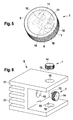
- the LED module 1 shown in Figures 1 to 4 is intended for installation in a not shown in the figures lighting unit. It comprises a cylindrical housing 2 made of aluminum, which in each case has a recess 3 at its two end faces and is thus designed to be open. Between the two recesses 3 is a disc-shaped base 4, which is integrally connected to the sleeve-shaped wall 5 of the housing 2.
- a total of four LED components 6 are added, which are each designed here as a surface-mounted LED chips.
- the individual LED chips 6 are arranged in a 2x2 array on a carrier board 7, which is mounted directly on the base 4. In this way, the LED chips 6 are thermally conductive connected via the carrier board 7 and the base 4 with the wall 5 of the module housing 2.
- the module housing 2 in this case represents a thermal contact element, via which the heat loss of the LED components 6 can be dissipated to the LED module 1 receiving luminous unit or to a heat sink 8 of a lighting unit.
- a circuit board 9 is accommodated, which forms a control unit 10 for the LED chips 6 with a drive circuit applied thereto.
- the control unit 10 is connected to the LED chips 6 via two contact pins 11 that are led through the base 4 in an insulating manner.
- the front end surfaces of the contact pins 11 are connected by bonding wires 12 to the carrier board 7 and with the LED chips 6 mounted thereon.
- the rear end regions of the contact pins 11 each contact a connection socket of the control unit 10 embedded in the printed circuit board 9.
- connection means 13 may be provided, such as connector or pins.
- a plastic primary optics 14 can be glued over the LED chips 6 and / or inserted into the corresponding recess 3, in particular clipped, as shown in Figure 5.
- the four LED chips 6 are arranged in a row next to one another on the carrier board 7. Basically, any number of LED chips 6 can be provided in any arrangement in the LED module 1, depending on the purpose.
- the back of the housing 2 can be completed by a suitable cover.
- a pre-assembled LED module 1 is obtained, in which a control unit 10 for driving the LED components 6 is already integrated.
- the control unit can also be arranged at other locations of the LED module 1, for example on the rear side and / or the front side of the carrier board 7 of the LED chips 6.
- the pre-assembled LED modules1 are later particularly quickly and easily inserted into suitable recesses 15 of a heat sink 8 of a lighting unit.
- the LED chips 6 can be soldered onto a carrier board 7 in the form of a driving silicon IC.
- the drive itself serves as a carrier for the LED chips.
- the integrated control can also be carried out in silicon carbide, which is characterized by good thermal properties. Such an integration would be particularly advantageous because some LED manufacturers silicon carbide is used as a substrate for the LEDs.
- the monolithic semiconductor lighting unit can be equipped by this chip-on-chip solution directly with an example. Phosphorus-active lighting part and an integrated control part, in which a drive by integrated circuits, sensors and / or other switching logic is already integrated.
- the number of steps required to produce an LED module can be reduced.
- an integrated drive for example in the form of an ASIC, a plurality of possibly different LED chips can also be arranged on a carrier and driven at the same time.
- the LED modules 1 preferably have on their housing 2 an outside knurling 16, via which they are positively and non-positively pressed into the recesses 15 of the heat sink 8. At the same time a particularly simple, yet highly accurate optical alignment of the individual LED modules 1 to each other is achieved, so that a subsequent adjustment of individual LEDs for the desired focusing of the lighting unit during assembly is not required.
- the LED modules 1 can be pressed directly into their predetermined by the recesses 15 positionally accurate alignment in the heat sink 8.
- the heat sink 8 shown in FIG. 6 has three recesses 15 in order to be able to record a total of three prefabricated LED modules 1 according to the invention, each with an integrated control unit.
- the heat sink 8 which also consists of aluminum, provided with cooling fins 17, via which the waste heat can be dissipated to the environment. Since the heat sink 8 is made of aluminum here as well as the housing 2 of the LED modules 1, not only results in a particularly good heat transfer due to the identical thermal expansion coefficient, but it is also a permanently secure interference fit between the module housings 2 and the heat sink 8 guaranteed ,
- the number and arrangement of the holes or recesses 15 as well as the shape of the heat sink 8 can be varied depending on the requirements of the associated lighting unit requirements.
- any orientation of the bores or recesses 15 in three-dimensional space is possible with a three-dimensional heat sink 8.
- the heat sink 8 may also be designed for a motor vehicle headlight.
- the recesses 15 are preferably introduced in a corresponding processing center in only a single clamping.
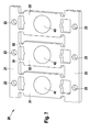
- FIG. 7 shows a metallic carrier strip, a so-called lead frame 20, to which a plurality of LED modules 1 can be attached.
- the carrier strip 20 is preferably made of copper or a copper alloy.
- the carrier strip 20 has a first mounting web 21 and a second mounting web 22, wherein the two mounting webs 21, 22 form parallel webs, in each of the mounting holes 23 are introduced.
- the carrier strip 20 can be mounted in a housing and optionally connected to further cooling elements.
- Support members 31, 32 and 33 which in the embodiment shown here form an approximate rectangular, planar surface, are held by thin support arms between the two webs 21, 22.
- each mounting surfaces 41, 42, 43 are sketched, where the respective LED modules 1, for example by gluing or can be applied by soldering.
- the module housing 2 preferably contacts the surface of the respective associated carrier element.
- the mounting webs 21, 22 are each connected only via thin connecting webs with the carriers 31, 32, 33. In FIG. 7, for reasons of clarity of the drawing, only two connecting webs 51, 52 are provided with a reference numeral. By means of the openings formed by the thin design of the connecting webs 51, the carriers 31, 32 can be cooled with air guided past them.
- connection webs in particular in an embodiment of a material with good heat conduction, that over the connecting webs 51, 52 heat to the mounting webs 21, 22 is led away for further dissipation.
- the attachment of the LED modules on the surface of the carrier 31, 32, 33 can be done by means known from the processing of power semiconductors manufacturing processes.
Landscapes
- Engineering & Computer Science (AREA)
- General Engineering & Computer Science (AREA)
- Physics & Mathematics (AREA)
- Microelectronics & Electronic Packaging (AREA)
- Optics & Photonics (AREA)
- Arrangement Of Elements, Cooling, Sealing, Or The Like Of Lighting Devices (AREA)
- Led Device Packages (AREA)
- Led Devices (AREA)
- Optical Couplings Of Light Guides (AREA)
Abstract
Description
Die vorliegende Erfindung betrifft ein LED-Modul, das zum Einbau in ein Leuchtaggregat bestimmt ist, wobei das LED-Modul mehrere LED-Bauelemente, elektrische Anschlussmittel, über die die LED-Bauelemente mit einer Stromversorgung des Leuchtaggregats verbunden werden können, und mindestens ein wärmeleitend mit den LED-Bauelementen verbundenes thermisches Kontaktelement, über das die Verlustwärme der LED-Bauelemente an das Leuchtaggregat bzw. an einen Kühlkörper des Leuchtaggregats abgeführt werden kann, umfasst.The present invention relates to an LED module, which is intended for installation in a lighting unit, wherein the LED module, a plurality of LED components, electrical connection means, via which the LED components can be connected to a power supply of the lighting unit, and at least one heat-conducting with the LED components connected thermal contact element, via which the heat loss of the LED components can be dissipated to the lighting unit or to a heat sink of the lighting unit comprises.
Derartige Leuchtaggregate können sowohl zu Zwecken der Innenraumbeleuchtung als auch bei der Außenbeleuchtung eingesetzt werden. Insbesondere ist ein Einsatz von solchen Leuchtaggregate auch in oder an Kraftfahrzeugen möglich. Als lichtabgebende LED-Bauelemente (LED = light emitting diode) können optische Halbleiterbauelemente in der Form von Leuchtdioden, insbesondere Leuchtdiodenchips (LED-Chips) eingesetzt werden. Üblicherweise wird dabei eine Vielzahl von LED-Bauelementen (im folgenden auch LEDs genannt) zu einem Array angeordnet, wobei die LEDs vorzugsweise als oberflächenmontiertes SMD-Element (SMD = surface mounted device) durch Löten oder Kleben auf einem Träger oder einer Leiterplatte montiert werden.Such lighting units can be used both for purposes of interior lighting and outdoor lighting. In particular, a use of such lighting units is also possible in or on motor vehicles. As light-emitting LED components (LED = light emitting diode), optical semiconductor components in the form of light-emitting diodes, in particular light-emitting diode chips (LED chips) can be used. Usually, a plurality of LED components (also called LEDs hereinafter) are arranged in an array, wherein the LEDs are preferably mounted as surface-mounted SMD (SMD) element by soldering or gluing on a support or a printed circuit board.
Nicht nur bei Kraftfahrzeugen werden zunehmend LEDs eingesetzt, da sie gegenüber konventionellen Glühlampen einige wesentliche Vorteile aufweisen. So haben LEDs eine längere Lebensdauer, eine geringere Baugröße sowie einen besseren Wirkungsgrad bei der Umwandlung elektrischer Energie in Licht. Ferner zeichnen sich LEDs durch eine Unempfindlichkeit gegenüber Stößen und Erschütterungen aus, was insbesondere bei Kraftfahrzeugen einen erheblichen Vorteil darstellt.Not only in motor vehicles, LEDs are increasingly being used because they have some significant advantages over conventional light bulbs. LEDs have a longer life, a smaller size and a better efficiency in the conversion of electrical energy into light. Furthermore, LEDs are characterized by a Insensitivity to shocks and shocks, which is a significant advantage, especially in motor vehicles.
Trotz der im Vergleich zu Glühlampen geringeren Wärmeabgabe muss vor dem Hintergrund einer ständig fortschreitenden Leistungssteigerung auch bei LEDs die als Verlust auftretende Abwärme abgeführt werden, um eine Überhitzung und damit eine Funktionsbeeinträchtigung oder sogar eine Zerstörung der LEDs zu verhindern. Üblicherweise wird die Abwärme von der Unterseite der LED-Bauelemente über ihre elektrischen Anschlüsse und/oder über einen als Wärmeanschluss dienenden dritten Kontakt an einen metallischen Kühlkörper abgeführt.Despite the lower heat dissipation compared to incandescent lamps, the waste heat that occurs as a loss has to be dissipated against the backdrop of constantly increasing performance, even in LEDs, in order to prevent overheating and thus functional impairment or even destruction of the LEDs. Usually, the waste heat is dissipated from the underside of the LED components via their electrical connections and / or via a serving as a heat connection third contact to a metallic heat sink.
Aus der
Um beispielsweise in einem Scheinwerfer eines Kraftfahrzeugs mehrere LEDs oder mehrere LED-Gruppen anzuordnen, werden üblicherweise flexible Leiterplatten in einer zweidimensionalen Ebene mit LEDs bestückt, und danach wird das so erhaltene flexible Gebilde auf einen Kühlkörper aufgeklebt. Der Kühlkörper kann dabei, wie es aus der
Deshalb werden zunehmend auch vorgefertigte LED-Leuchtmodule (kurz auch LED-Module genannt) eingesetzt, bei denen eine bestimmte Anzahl von LEDs in einer bestimmten Anordnung zu einem Modul zusammengefasst sind, um die geforderte Menge Licht für bestimmte Applikationen zu erreichen. Derartige Module lassen sich relativ einfach in einem Leuchtaggregat montieren. Die Ansteuerung der LED-Module bzw. der einzelnen LEDs erfolgt mittels spezieller Treiberschaltungen, die als externe Steuereinheit außerhalb der jeweiligen Module angeordnet und separat zu montieren ist.Therefore, increasingly prefabricated LED lighting modules (also called LED modules) are used in which a certain number of LEDs are combined in a particular arrangement into a module to achieve the required amount of light for certain applications. Such modules can be relatively easy to mount in a lighting unit. The control of the LED modules or the individual LEDs by means of special driver circuits, which is arranged as an external control unit outside the respective modules and to be mounted separately.
Aus der
Aufgabe der vorliegenden Erfindung ist es, ein verbessertes LED-Modul der eingangs genannten Art zu schaffen, das eine noch einfachere und schnellere Montage in ein Leuchtaggregat ermöglicht.Object of the present invention is to provide an improved LED module of the type mentioned, which allows an even easier and faster installation in a lighting unit.
Diese Aufgabe wird durch ein LED-Modul nach Anspruch 1 gelöst.This object is achieved by an LED module according to
Die der vorliegenden Erfindung zugrundeliegende Idee besteht darin, dass eine Steuereinheit zur Ansteuerung der LED-Bauelemente mit den anderen Komponenten des LED-Moduls zu einer einheitlichen Baugruppe vereinigt ist, indem die Steuereinheit in das LED-Modul integriert wird. Insbesondere kann die Steuereinheit eine elektronische Schaltung umfassen, die als IC (IC = integrated circuit bzw. integrierte Schaltung) ausgeführt ist.The idea underlying the present invention is that a control unit for controlling the LED components is combined with the other components of the LED module to form a unitary assembly by integrating the control unit into the LED module. In particular, the control unit may comprise an electronic circuit designed as an integrated circuit (IC).
Auf dieses Weise wird eine vorgefertigte, kompakte und einfach zu verbauende LED-Baugruppe geschaffen, die neben den LEDs, den elektrischen Anschlussmitteln und dem thermischen Kontaktelement auch bereits die zur Ansteuerung des LED-Moduls bzw. die zur Ansteuerung der LEDs erforderlichen Elemente enthält. Die bisherige Trennung von Leuchtteil und Steuerteil entfällt damit.In this way, a prefabricated, compact and easy-to-install LED assembly is created, which already contains in addition to the LEDs, the electrical connection means and the thermal contact element for driving the LED module or the required for driving the LEDs elements. The previous separation of lighting part and control part thus eliminated.
Das erfindungsgemäße LED-Modul nach Anspruch 1 weist gegenüber den vorbekannten Ausführungsformen vor allem den Vorteil auf, dass eine separate Montage und anschließende Verbindung einer externen Steuereinheit für das LED-Modul nicht mehr erforderlich ist, was den Aufwand und damit auch die Herstellungskosten eines mit derartigen LED-Modulen ausgestatteten Leuchtaggregats deutlich reduziert.The LED module according to the invention according to
Das LED-Modul kann dabei sowohl mehrere einzelne LED-Chips als auch - alternativ oder zusätzlich - ein oder mehrere strukturierte Substrate mit eingebetteten, insbesondere eingelöteten LED-Chips umfassen.The LED module may comprise both a plurality of individual LED chips and - alternatively or additionally - one or more structured substrates with embedded, in particular soldered, LED chips.
Vorteilhafte Weiterbildungen und Verbesserungen des erfindungsgemäßen LED-Moduls ergeben sich aus den abhängigen Ansprüchen.Advantageous developments and improvements of the LED module according to the invention will become apparent from the dependent claims.
So ist es beispielsweise besonders günstig, wenn die Steuereinheit mindestens eine Treiberschaltung umfasst, durch welche die LED-Bauelemente einzeln oder gruppenweise angesteuert werden können..For example, it is particularly advantageous if the control unit comprises at least one driver circuit, by means of which the LED components can be controlled individually or in groups.
Besonders vorteilhaft ist es ferner, wenn die Steuereinheit mindestens eine Mehrkanal-Ansteuer-Schaltung umfasst, durch die auch RGB-LEDs angesteuert werden können. Die Verwendung eines Mehrkanal-Ansteuer-ICs gestattet somit einen flexiblen Einsatz der erfindungsgemäßen LED-Module auch in Leuchtaggregaten für solche Bereiche, in denen es auf mehrfarbige Lichtsignale ankommt.It is furthermore particularly advantageous if the control unit comprises at least one multi-channel drive circuit, by means of which RGB LEDs can also be activated. The use of a multi-channel drive IC thus allows flexible use of the LED modules according to the invention also in lighting units for those areas in which it depends on multi-colored light signals.
Gemäß einer besonders bevorzugten Ausführungsform der Erfindung ist vorgesehen, dass das thermische Kontaktelement durch ein offenes oder geschlossenes Gehäuse aus einem wärmeleitenden Material gebildet wird, in welchem die LED-Bauelemente, die elektrischen Anschlussmittel, die Steuereinheit sowie gegebenenfalls vorgesehene weitere Komponenten des LED-Moduls angeordnet sind. Hierdurch wird eine robuste und besonders kompakte Ausbildung des LED-Moduls erzielt, die nicht nur leicht handzuhaben ist, sondern gleichzeitig auch einen besonders effektiven Übergang der abzuführenden Wärme ermöglicht. So kann bei einer geeigneten Anbringung des Moduls in einer wärmeleitenden Aufnahme des Leuchtaggregats, insbesondere unmittelbar in dem Kühlkörper des Leuchtaggregats, die Wärme über die Oberfläche des gesamten Modulgehäuses abgeführt werden. Das Gehäuse kann dabei eine beliebig geformte Außenkontur aufweisen, die an die an das Leuchtaggregat gestellten Anforderungen angepasst werden kann. Vorzugsweise besteht das Gehäuse aus einem gut wärmeleitendem Material, insbesondere aus Kupfer oder Aluminium.According to a particularly preferred embodiment of the invention it is provided that the thermal contact element is formed by an open or closed housing made of a thermally conductive material, in which the LED components, the electrical connection means, the control unit and possibly provided further components of the LED module are. As a result, a robust and particularly compact design of the LED module is achieved, which is not only easy to handle, but at the same time also allows a particularly effective transition of dissipated heat. Thus, with a suitable attachment of the module in a thermally conductive recording of the lighting unit, especially directly in the heat sink of the lighting unit, the heat can be dissipated through the surface of the entire module housing. The housing can be any shape Having outer contour, which can be adapted to the requirements placed on the lighting unit. Preferably, the housing consists of a good heat-conducting material, in particular copper or aluminum.
Besonders vorteilhaft ist es dabei, wenn in oder an dem Gehäuse ein scheibenförmiger Sockel aus einem gut wärmeleitenden Material vorgesehen ist, auf dem die LED-Bauelemente aufgenommen sind. Die Abwärme kann dann über den Sockel, der vorzugsweise speziell an die Anzahl und Größe der aufzunehmenden LEDs des Moduls angepasst ist, je nach Art der Modulaufnahme entweder direkt oder mittelbar über das Gehäuse weiter an das Leuchtaggregat abgeführt werden. Dabei kann die Steuereinheit entweder auf der gleichen Seite des Sockels wie die LEDs angebracht sein oder der Sockel wird mit elektrischen Durchführungen versehen und so ausgebildet, dass die Steuereinheit auf der den LEDs gegenüberliegenden Rückseite des Sockels angeordnet ist. Der Sockel ist insbesondere einstückig mit dem Gehäuse ausgeführt und besteht somit ebenfalls vorzugsweise aus Kupfer oder Aluminium.It is particularly advantageous if in or on the housing, a disc-shaped base is provided from a good heat-conducting material on which the LED components are added. The waste heat can then be dissipated via the base, which is preferably adapted specifically to the number and size of the male LEDs of the module, depending on the type of module recording either directly or indirectly via the housing further to the lighting unit. In this case, the control unit can be mounted either on the same side of the base as the LEDs or the base is provided with electrical feedthroughs and formed so that the control unit is arranged on the opposite side of the LEDs back of the base. The base is in particular made in one piece with the housing and therefore also preferably consists of copper or aluminum.
Günstig für eine gewünschte Lichtabgabe kann es weiterhin sein, wenn optische Mittel, insbesondere eine Kunststoffoptik oder optische Konvertierungsmittel, beispielsweise ein optisches Füllmedium zur Farbumwandlung des von den LEDs des Moduls emittierten Lichts in dem Gehäuse aufgenommen oder darin eingepasst sind. Vorzugsweise kann so auch ein zu einer Stirnseite hin offenes Gehäuse durch eine entsprechend ausgebildete Primäroptik abgeschlossen werden, um eine bestimmte Fokussierung zu erzielen. Auf besonders einfache Weise kann eine Kunststoffoptik per Clip-Montage in das Gehäuse eingesetzt werden.It may also be favorable for a desired light output if optical means, in particular plastic optics or optical conversion means, for example an optical filling medium for color conversion of the light emitted by the LEDs of the module, are accommodated or fitted in the housing. Preferably, a housing which is open towards an end side can thus also be terminated by a suitably designed primary optics in order to achieve a specific focusing. In a particularly simple way, a plastic look can be used by clip-mounting in the housing.
Eine besonders leichte Montage ergibt sich dann, wenn die LED-Bauelemente zunächst auf einer Trägerplatine vormontiert und danach in das LED-Modul eingebracht werden. Vorteilhaft ist es hierbei, eine Ansteuerungsschaltung auf der Trägerplatine anzuordnen, da hierdurch auf eine externe Ansteuerschaltung für die LED-Bauelemente selbst verzichtet werden kann. Hierdurch können die Arbeitsschritte zur Herstellung eines entsprechenden LED-Moduls verringert werden, da die lichterzeugenden LED-Bauelemente und die Ansteuerung in einem Arbeitsgang aufgebracht werden können.A particularly easy assembly results when the LED components are first preassembled on a carrier board and then introduced into the LED module. It is advantageous here to arrange a drive circuit on the carrier board, as this can be dispensed with an external drive circuit for the LED components themselves. As a result, the steps for producing a corresponding LED module can be reduced since the light-generating LED components and the control can be applied in one operation.
Um einen dauerhaft effektiven Wärmeübergang zu gewährleisten, wird ferner vorgeschlagen, dass die Außenseiten des Gehäuses zumindest teilweise eine Zahnung oder eine Rändelung aufweisen. Über eine derartige gezahnte oder gerändelte Gehäusekontur kann das Gehäuse des LED-Moduls besonders gut wärmeleitend in einen Kühlkörper des Leuchtaggregats eingepresst werden.In order to ensure a permanently effective heat transfer, it is further proposed that the outer sides of the housing at least partially have a toothing or knurling. About such a toothed or knurled housing contour, the housing of the LED module can be pressed particularly good thermal conductivity in a heat sink of the lighting unit.
Gegenstand der vorliegenden Erfindung ist ferner ein Leuchtaggregat mit mehreren LED-Bauelementen und einem Kühlkörper, über den die Verlustwärme der LEDs abgeführt werden kann, wobei das Leuchtaggregat ein oder mehrere LED-Module der vorangehend beschriebenen Art umfasst. Ein derartiges Leuchtaggregat ist aufgrund der vorgefertigten LED-Module mit integrierter Steuereinheit besonders schnell und einfach zu montieren, was eine kostengünstige Fertigung ermöglicht.The subject matter of the present invention is furthermore a lighting unit with a plurality of LED components and a heat sink, via which the heat loss of the LEDs can be dissipated, wherein the lighting unit comprises one or more LED modules of the type described above. Such a lighting unit is due to the prefabricated LED modules with integrated control unit particularly fast and easy to assemble, allowing a cost-effective production.
Besonders vorteilhaft ist es dabei, wenn das oder die LED-Module jeweils ein Gehäuse der vorgenannten Art aufweisen, welches kraftschlüssig in dem Kühlkörper des Leuchtaggregats aufgenommen ist. Hierdurch wird bei einer relativ einfachen und robusten Konstruktion nicht nur eine sehr schnelle und einfache Montage ermöglicht, sondern es wird vor allem auch eine zur gewünschten Ausrichtung der LED-Bauelemente erforderlichen Justierung auf ein Minimum beschränkt oder sogar vollständig entbehrlich gemacht. Vorteilhafterweise werden die Gehäuse der vorgefertigten LED-Module beim kraftschlüssigen Einsetzen in den Kühlkörper direkt so aufgenommen, dass die gewünschte Fokussierung der Leuchtdioden quasi automatisch auf besonders schnelle und einfache Art und Weise erhalten wird. Gleichzeitig wird auf diese Weise eine schnelle und besonders effektive Wärmeverteilung (Heatspreader Funktion) ermöglicht.It is particularly advantageous if the one or more LED modules each have a housing of the aforementioned type, which is received positively in the heat sink of the lighting unit. As a result, not only a very quick and easy installation is made possible with a relatively simple and robust construction, but it is mainly limited to a required alignment of the LED components adjustment to a minimum or even made completely unnecessary. Advantageously, the housings of the prefabricated LED modules are directly accommodated in the frictional insertion into the heat sink in such a way that the desired focusing of the light-emitting diodes is obtained virtually automatically in a particularly fast and simple manner. At the same time, a fast and particularly effective heat distribution (heat spreader function) is made possible in this way.
Eine besonders präzise Ausrichtung des LED-Moduls kann dadurch erreicht werden, dass das Gehäuse in eine Öffnung oder in eine Vertiefung des Kühlkörpers des Leuchtaggregats eingesetzt, vorzugsweise eingepresst wird. Das Einpressen des Modulgehäuses in eine komplementäre Aufnahme des Kühlkörpers gestattet dabei ein besonders schnelle, kraft- und formschlüssige Aufnahme und Ausrichtung des LED-Moduls. Vorteilhafterweise können auch mehrere Gehäuse einer Mehrzahl von LED-Modulen in einen gemeinsamen Kühlkörper eingepresst werden, wodurch besonders enge Lagetoleranzen der einzelnen LED-Module zueinander eingehalten werden können und eine aufwändige optische Ausrichtung der LED-Module zueinander bei der Montage nicht mehr erforderlich ist. Bei der Herstellung eines derartigen Leuchtaggregats ist es zur Erzielung einer hochexakten optischen Ausrichtung besonders vorteilhaft, wenn für die Aufnahme mehrerer LED-Module mehrere Öffnungen und/oder Vertiefungen gleichzeitig und/oder in einer einzigen Aufspannung des Kühlkörpers in den Kühlkörper eingebracht werden, was vorteilhafterweise mit entsprechenden Bearbeitungszentren ausgeführt werden kann.A particularly precise alignment of the LED module can be achieved in that the housing is inserted into an opening or in a recess of the heat sink of the lighting unit, preferably pressed. The pressing of the module housing in a complementary recording of the heat sink allows a particularly fast, positive and positive recording and alignment of the LED module. Advantageously, a plurality of housing of a plurality of LED modules can be pressed into a common heat sink, whereby particularly close tolerances of the individual LED modules can be maintained and a complex optical alignment of the LED modules to each other during assembly is no longer necessary. In the production of such a lighting unit, it is particularly advantageous for achieving a highly accurate optical alignment when multiple openings and / or wells are simultaneously and / or introduced in a single clamping of the heat sink in the heat sink for receiving a plurality of LED modules, which advantageously with corresponding machining centers can be executed.
Unabhängig von optischen Anwendungen und Leuchtaggregaten sind beispielsweise aus der
Es ist ferner vorteilhaft, den Kühlkörper als einen metallischen Trägerstreifen, einen sogenannten Lead-Frame, auszuführen. Derartige Lead-Frames sind bereits zur Kühlung von Leistungshalbleitern bekannt und können daher kostengünstig hergestellt und verbaut werden. Sie stellen eine hinreichend gute Wärmesenke für die LED und deren Ansteuerung dar. Dadurch dass auf dem Lead-Frame eine einseitige Bestückung erfolgen kann, werden die Fertigungsprozesse zur Herstellung eines Leuchtaggregats mit LED-Modulen vereinfacht. Besonders vorteilhaft wird dabei der Lead-Frame aus Kupfer ausgeführt, da Kupfer besonders gut die Wärme abführen kann, die bei der Lichterzeugung entsteht.It is also advantageous to carry out the heat sink as a metallic carrier strip, a so-called lead frame. Such lead frames are already known for cooling power semiconductors and can therefore be manufactured and installed inexpensively. They provide a sufficiently good heat sink for the LED and its control. The fact that on the lead frame one-sided assembly can take place, the manufacturing processes for the production of a lighting unit with LED modules are simplified. The lead frame made of copper is particularly advantageous in this case since copper can dissipate the heat which is produced when generating light particularly well.
Besonders vorteilhaft ist es, wenn das erfindungsgemäße Leuchtaggregat ein Scheinwerfer, insbesondere ein Kraftfahrzeug-Scheinwerfer ist, der einen Scheinwerferkühlkörper umfasst, in dem mindestens ein Modulgehäuse der vorangehend beschriebenen Art kraftschlüssig aufgenommen, vorzugsweise eingepresst oder eingeschraubt ist. Die vorliegende Erfindung kann somit insbesondere im Automotive-Bereich, aber auch bei generellen Beleuchtungsanwendungen in vorteilhafter Weise zum Einsatz kommen.It is particularly advantageous if the lighting unit according to the invention is a headlamp, in particular a motor vehicle headlamp, comprising a headlamp heat sink in which at least one module housing of the type described above is positively received, preferably pressed in or screwed in. The present invention can thus be used advantageously in particular in the automotive sector, but also in general lighting applications.
Kurze Beschreibung der ZeichnungenBrief description of the drawings
In den Zeichnungen sind Ausführungsbeispiele der Erfindung dargestellt, die in der nachfolgenden Beschreibung näher erläutert werden.
Es zeigen:
- Figur 1: dreidimensionale Darstellung eines erfindungsgemäßen LED-Moduls von der Vorderseite;
- Figur 2: Darstellung des LED-
Moduls aus Figur 1 von der Rückseite; - Figur 3: Darstellung des LED-
Moduls aus Figur 2 mit abgenommener Steuereinheit; - Figur 4: Schnittdarstellung des LED-
Moduls aus Figur 1; - Figur 5: dreidimensionale Darstellung einer zweiten Ausführungsform eines erfindungsgemäßen LED-Moduls; und
- Figur 6: dreidimensionale Darstellung eines Kühlkörpers eines Leuchtaggregats mit drei LED-
Modulen nach Figur 5. Figur 7 zeigt ein Ausführungsbeispiel für einen metallischen Trägerstreifen als einen Kühlkörper für ein erfindungsgemäßes Leuchtaggregat mit mehreren LED-Modulen.
Show it:
- Figure 1: three-dimensional view of an LED module according to the invention from the front;
- Figure 2: representation of the LED module of Figure 1 from the back;
- FIG. 3: illustration of the LED module from FIG. 2 with the control unit removed;
- Figure 4: sectional view of the LED module of Figure 1;
- FIG. 5 shows a three-dimensional illustration of a second embodiment of an LED module according to the invention; and
- 6 shows a three-dimensional view of a heat sink of a lighting unit with three LED modules according to FIG. 5.
- Figure 7 shows an embodiment of a metallic carrier strip as a heat sink for a lighting unit according to the invention with a plurality of LED modules.
Das in den Figuren 1 bis 4 gezeigte LED-Modul 1 ist zum Einbau in ein in den Figuren nicht dargestelltes Leuchtaggregat bestimmt. Es umfasst ein aus Aluminium bestehendes zylindrisches Gehäuse 2, das an seinen beiden Stirnseiten jeweils eine Vertiefung 3 aufweist und insofern offen ausgebildet ist. Zwischen den beiden Vertiefungen 3 befindet sich ein scheibenförmiger Sockel 4, der einstückig mit der hülsenförmigen Wandung 5 des Gehäuses 2 verbunden ist.The
In der vorderseitigen Vertiefung 3 sind insgesamt vier LED-Bauelemente 6 aufgenommen, die hier jeweils als oberflächenmontierte LED-Chips ausgeführt sind. Die einzelnen LED-Chips 6 sind dabei in einem 2x2-Array auf einer Trägerplatine 7 angeordnet, die direkt auf dem Sockel 4 befestigt ist. Auf diese Weise sind die LED-Chips 6 wärmeleitenden über die Trägerplatine 7 und den Sockel 4 mit der Wandung 5 des Modulgehäuses 2 verbunden. Das Modulgehäuse 2 stellt dabei ein thermisches Kontaktelement dar, über das die Verlustwärme der LED-Bauelemente 6 an das das LED-Modul 1 aufnehmende Leuchtaggregat bzw. an einen Kühlkörper 8 eines Leuchtaggregats abgeführt werden kann.In the front recess 3 a total of four
In der zweiten Vertiefung 3 des Modulgehäuses 2 ist eine Platine 9 aufgenommen, die mit einer darauf aufgebrachten Ansteuerschaltung eine Steuereinheit 10 für die LED-Chips 6 bildet. Über zwei isolierend durch den Sockel 4 hindurchgeführte Kontaktstifte 11 ist die Steuereinheit 10 mit den LED-Chips 6 verbunden. Dazu sind die vorderseitigen Endflächen der Kontaktstifte 11 durch Bonddrähte 12 mit der Trägerplatine 7 bzw. mit den darauf angebrachten LED-Chips 6 verbunden. Die rückseitigen Endbereiche der Kontaktstifte 11 kontaktieren jeweils eine in der Platine 9 eingelassene Anschlussbuchse der Steuereinheit 10.In the
Die Rückseite der Platine 9 ist mit einem hier als Flachkabel ausgeführten Anschlusskabel 13 verbunden, über dessen Leitungen einerseits die LED-Chips 6 mit Strom versorgt werden können und andererseits auch der Steuereinheit 10 externe Steuersignale zuführbar sind. Statt eines Kabels können auch andere Anschlussmittel 13 vorgesehen sein, beispielsweise Anschlussstecker oder Anschlussstifte.The rear side of the
Um das LED-Modul 1 vorderseitig abzuschließen, kann eine aus Kunststoff bestehende Primäroptik 14 über die LED-Chips 6 aufgeklebt und/oder in die entsprechende Vertiefung 3 eingesetzt, insbesondere eingeclipst werden, wie in Figur 5 dargestellt ist. Bei dem hier gezeigten LED-Modul 1 sind die vier LED-Chips 6 in einer Reihe nebeneinander auf der Trägerplatine 7 angeordnet. Grundsätzlich können je nach Einsatzzweck beliebig viele LED-Chips 6 in beliebiger Anordnung in dem LED-Modul 1 vorgesehen werden. Auch die Rückseite des Gehäuses 2 kann durch eine geeignete Abdeckung abgeschlossen werden.To complete the front side of the
In jedem Fall wird ein fertig vormontiertes LED-Modul 1 erhalten, in das bereits eine Steuereinheit 10 zur Ansteuerung der LED-Bauelemente 6 integriert ist. Selbstverständlich kann die Steuereinheit dabei auch an anderen Stellen des LED-Moduls 1, beispielsweise auf der Rückseite und/oder der Vorderseite der Trägerplatine 7 der LED-Chips 6 angeordnet sein. Die vormontierten LED-Module1 sind später besonders schnell und einfach in geeignete Ausnehmungen 15 eines Kühlkörpers 8 eines Leuchtaggregats einsetzbar.In any case, a
In einer ersten Ausführungsform können hierbei die LED-Chips 6 auf eine Trägerplatine 7 in Form eines Ansteuerungs-Silizium-ICs aufgelötet werden. Somit dient in dieser Ausführungsform die Ansteuerung selbst als Träger für die LED-Chips. In einer weiteren Ausführungsform kann die integrierte Steuerung auch in Silizium- Carbid vorgenommen werden, das sich durch gute thermische Eigenschaften auszeichnet. Eine solche Integration wäre insbesondere daher vorteilhaft, da bei einigen LED-Herstellern SiliziumCarbid als Substrat für die LEDs verwendet wird. Die monolitische Halbleiter-Leuchteinheit kann durch diese Chip-on-Chip-Lösung unmittelbar mit einem bspw. Phosphor-aktivem Leuchtteil und einem integrierten Steuerteil ausgestattet sein, bei dem eine Ansteuerung durch integrierte Schaltkreise, Sensoren und/odere weitere Schaltlogik bereits integriert ist. Durch die einseitige Chip-Montage auf dem Diodensockel oder einem Lead-Frame kann dabei die Anzahl der zur Herstellung eines LED-Moduls erforderlichen Arbeitsschritte verringert werden. Zudem können druch eine integrierte Ansteuerung, beispielsweise in Form eines ASICs, auch mehrere gegebenenfalls unterschiedliche LED-Chips auf einem Träger angeordnet und zugleich angesteuert werden.In a first embodiment, the
Um eine besonders effektive Abgabe der Verlustwärme an den Kühlkörper 2 zu gewährleisten können die LED-Module 1 vorzugsweise an ihrem Gehäuse 2 eine außenseitige Rändelung 16 aufweisen, über die sie form- und kraftschlüssig in die Ausnehmungen 15 des Kühlkörpers 8 eingepresst werden. Gleichzeitig ist dabei eine besonders einfache, aber dennoch hoch genaue optische Ausrichtung der einzelnen LED-Module 1 zueinander erzielbar, so dass eine nachträgliche Justierung einzelner LEDs zur gewünschten Fokussierung des Leuchtaggregats bei der Montage nicht erforderlich ist. Die LED-Module 1 können direkt in ihrer durch die Ausnehmungen 15 vorgegebenen positionsgenauen Ausrichtung in den Kühlkörper 8 eingepresst werden.In order to ensure a particularly effective release of the heat loss to the
Der in Figur 6 dargestellte Kühlkörper 8 weist drei Ausnehmungen 15 auf, um insgesamt drei erfindungsgemäß vorgefertigte LED-Module 1 mit jeweils einer integrierten Steuereinheit kraftschlüssig aufnehmen zu können. Um eine besonders effektive Kühlung zu erreichen ist der Kühlkörper 8, der ebenfalls aus Aluminium besteht, mit Kühlrippen 17 versehen, über die die Abwärme an die Umgebung abgeführt werden kann. Da der Kühlkörper 8 hier ebenso wie die Gehäuse 2 der LED-Module 1 aus Aluminium gefertigt ist, ergibt sich aufgrund der identischen Wärmeausdehnungskoeffizienten nicht nur eine besonders gute Wärmeübertragung, sondern es ist auch eine dauerhaft sichere Presspassung zwischen den Modulgehäusen 2 und dem Kühlkörper 8 gewährleistet.The heat sink 8 shown in FIG. 6 has three
Auch hier kann die Anzahl und Anordnung der Bohrungen bzw. Ausnehmungen 15 ebenso wie die Formgebung des Kühlkörpers 8 je nach den an das zugehörige Leuchtaggregat gestellten Anforderungen variiert werden. Insbesondere sind bei einem dreidimensionalen Kühlkörper 8 beliebige Ausrichtungen der Bohrungen oder Ausnehmungen 15 im dreidimensionalen Raum möglich. Insbesondere kann der Kühlkörper 8 auch für einen KFZ-Scheinwerfer ausgebildet sein.Again, the number and arrangement of the holes or recesses 15 as well as the shape of the heat sink 8 can be varied depending on the requirements of the associated lighting unit requirements. In particular, any orientation of the bores or recesses 15 in three-dimensional space is possible with a three-dimensional heat sink 8. In particular, the heat sink 8 may also be designed for a motor vehicle headlight.
Um eine hochpräzise Ausrichtung der LED-Module 1 im Kühlkörper 8 zu erreichen, werden die Ausnehmungen 15 vorzugsweise in einem entsprechenden Bearbeitungszentrum in nur einer einzigen Aufspannung eingebracht.In order to achieve a high-precision alignment of the
In der Figur 7 ist ein metallischer Trägerstreifen, ein sogenannter Lead-Frame 20, gezeigt, an dem mehrere LED-Module 1 angebracht werden können. Der Trägerstreifen 20 ist dabei bevorzugt aus Kupfer oder aus einer Kupferlegierung ausgeführt. Der Trägerstreifen 20 weist einen ersten Montagesteg 21 und einen zweiten Montagesteg 22 auf, wobei die beiden Montagestege 21, 22 parallel verlaufende Stege ausbilden, in die jeweils Montageöffnungen 23 eingebracht sind. Mittels den Montageöffnungen 23 kann der Trägerstreifen 20 in einem Gehäuse montiert und gegebenenfalls mit weiteren Kühlelementen verbunden werden. Zwischen den beiden Stegen 21, 22 sind über dünne Haltearme jeweils Trägerelemente 31, 32 und 33 gehalten, die in dem hier gezeigten Ausführungsbeispiel eine ungefähre rechteckige, plane Oberfläche ausbilden. Auf den planen Oberflächen der Trägerelemente 31, 32, 33 sind jeweils Montageflächen 41, 42, 43 skizziert, an denen die jeweiligen LED-Module 1 beispielsweise durch Kleben oder durch Löten aufgebracht werden können. Das Modulgehäuse 2 kontaktiert hierbei bevorzugt die Oberfläche des jeweils zugehörigen Trägerelements. Die Montagestege 21, 22 sind jeweils nur über dünne Verbindungsstege mit den Trägern 31, 32, 33 verbunden. In der Figur 7 sind aus Gründen der Übersichtlichkeit der Zeichnung nur zwei Verbindungsstege 51, 52 mit einem Bezugszeichen versehen. Mittels der durch die dünne Ausführung der Verbindungsstege 51 entstehenden Öffnungen können die Träger 31, 32 mit an ihnen vorbeigeleiteter Luft gekühlt werden. Ferner erlauben jedoch die Verbindungsstege, insbesondere bei einer Ausführung aus einem Material mit guter Wärmeleitung, dass über die Verbindungsstege 51, 52 Wärme an die Montagestege 21, 22 zur weiteren Ableitung weggeführt wird. Die Anbringung der LED-Module auf der Oberfläche der Träger 31, 32, 33 kann mittels aus der Verarbeitung von Leistungshalbleitern bekannten Fertigungsprozessen erfolgen.FIG. 7 shows a metallic carrier strip, a so-called
Claims (15)
dadurch gekennzeichnet,
dass eine Steuereinheit (10) zur Ansteuerung der LED-Bauelemente (6) in das LED-Modul (1) integriert ist.LED module for installation in a lighting unit, wherein the LED module (1) a plurality of LED components (6), electrical connection means (13) via which the LED components (6) are connectable to a power supply of the lighting unit, and at least a thermal contact element (2, 5) via which the heat loss of the heat-conducting associated LED components (6) can be dissipated to the lighting unit,
characterized,
that a control unit (10) for driving the LED components (6) in the LED module (1) is integrated.
dass die Steuereinheit (10) mindestens eine Mehrkanal-Ansteuer-Schaltung umfasst, durch die RGB-LED-Bauelemente (6) ansteuerbar sind.LED module according to claim 1 or 2, characterized
that the control unit (10) comprises at least one multichannel driver circuit are controlled by the RGB LED components (6).
dadurch gekennzeichnet, dass es mindestens ein LED-Modul (1) nach einem der vorherigen Ansprüche umfasst.Illuminating unit with a plurality of LED components (6) and a heat sink (8, 20), via which the heat loss of the LED components (6) can be dissipated,
characterized in that it comprises at least one LED module (1) according to one of the preceding claims.
Applications Claiming Priority (2)
| Application Number | Priority Date | Filing Date | Title |
|---|---|---|---|
| DE102006054180 | 2006-11-16 | ||
| DE102007024390A DE102007024390A1 (en) | 2006-11-16 | 2007-05-25 | LED module with integrated control |
Publications (2)
| Publication Number | Publication Date |
|---|---|
| EP1923626A1 true EP1923626A1 (en) | 2008-05-21 |
| EP1923626B1 EP1923626B1 (en) | 2009-08-19 |
Family
ID=39027610
Family Applications (2)
| Application Number | Title | Priority Date | Filing Date |
|---|---|---|---|
| EP07118265A Not-in-force EP1923627B1 (en) | 2006-11-16 | 2007-10-11 | Integrated control of LED assemblies |
| EP07118261A Expired - Fee Related EP1923626B1 (en) | 2006-11-16 | 2007-10-11 | LED module with integrated control |
Family Applications Before (1)
| Application Number | Title | Priority Date | Filing Date |
|---|---|---|---|
| EP07118265A Not-in-force EP1923627B1 (en) | 2006-11-16 | 2007-10-11 | Integrated control of LED assemblies |
Country Status (4)
| Country | Link |
|---|---|
| EP (2) | EP1923627B1 (en) |
| AT (1) | ATE440250T1 (en) |
| DE (3) | DE102007024390A1 (en) |
| ES (2) | ES2329522T3 (en) |
Cited By (8)
| Publication number | Priority date | Publication date | Assignee | Title |
|---|---|---|---|---|
| WO2010060420A1 (en) * | 2008-11-28 | 2010-06-03 | Osram Opto Semiconductors Gmbh | Optoelectronic lamp |
| WO2010145925A1 (en) * | 2009-06-15 | 2010-12-23 | Osram Gesellschaft mit beschränkter Haftung | Cooling member for semiconductor light emitting elements |
| WO2011139548A3 (en) * | 2010-05-04 | 2012-03-22 | Xicato, Inc. | Led illumination device with communication port for transmitting information associated with the device |
| WO2013120962A1 (en) * | 2012-02-16 | 2013-08-22 | Osram Gmbh | Light-emitting module |
| WO2016124776A1 (en) * | 2015-02-05 | 2016-08-11 | Valeo Vision | Device for connecting a light source to an electrical power supply device |
| EP2623851A4 (en) * | 2010-09-28 | 2018-04-18 | Koito Manufacturing Co., Ltd. | Circuit module, light-emitting module, and vehicle lamp |
| EP3382269A1 (en) * | 2017-03-30 | 2018-10-03 | Valeo North America, Inc. | A folded heat sink with electrical connection protection |
| EP3495720A1 (en) * | 2017-12-07 | 2019-06-12 | Valeo Vision | Light module for a motor vehicle |
Families Citing this family (9)
| Publication number | Priority date | Publication date | Assignee | Title |
|---|---|---|---|---|
| DE102009054620A1 (en) | 2009-12-14 | 2011-06-16 | Robert Bosch Gmbh | Light module i.e. LED module, for use in light assembly utilized as e.g. external illumination in motor vehicle, has recess formed in front side of socket such that recess accommodates electric and electronic components of controller |
| DE102009060790A1 (en) * | 2009-12-22 | 2011-06-30 | Automotive Lighting Reutlingen GmbH, 72762 | Light module for a lighting device of a motor vehicle and lighting device of a motor vehicle with such a light module |
| DE102010003364A1 (en) * | 2010-03-26 | 2011-11-17 | Osram Gesellschaft mit beschränkter Haftung | Lighting device for vehicle headlights, has lighting module with semiconductor light source and cover, where cover is attached at lighting module by seal seat |
| DE102010029227A1 (en) * | 2010-05-21 | 2011-11-24 | Osram Gesellschaft mit beschränkter Haftung | lighting device |
| DE102010031055B4 (en) | 2010-07-07 | 2023-02-23 | Robert Bosch Gmbh | Sensor module and method of manufacturing a sensor module |
| DE102011005047B3 (en) | 2011-03-03 | 2012-09-06 | Osram Ag | lighting device |
| DE102011076122A1 (en) * | 2011-05-19 | 2012-11-22 | Olympus Winter & Ibe Gmbh | Steam-sterilizable light source for medical device i.e. endoscope, for minimum-invasive treatment in body, has lamp whose connection part is connected with housing such that operating temperature of lamp is derivable to side of housing |
| DE102014109292A1 (en) | 2014-07-03 | 2016-01-07 | Hellmann Components Ug | Installation indicator |
| US10180248B2 (en) | 2015-09-02 | 2019-01-15 | ProPhotonix Limited | LED lamp with sensing capabilities |
Citations (6)
| Publication number | Priority date | Publication date | Assignee | Title |
|---|---|---|---|---|
| DE19528459A1 (en) * | 1995-08-03 | 1997-02-13 | Garufo Gmbh | LED display apparatus with carrier plate - has heat carrier plates connected to transfer heat from carrier plate to heat dissipation surface |
| WO2001014789A1 (en) * | 1999-08-23 | 2001-03-01 | Dialight Corporation | Led obstruction lamp |
| WO2002097884A1 (en) | 2001-05-26 | 2002-12-05 | Gelcore, Llc | High power led module for spot illumination |
| WO2004079256A1 (en) | 2003-03-06 | 2004-09-16 | Space Cannon Vh S.P.A. | Led light projector |
| US20060007013A1 (en) | 2004-07-08 | 2006-01-12 | Honeywell International Inc. | White LED anti-collision light utilizing light-emitting diode (LED) technology |
| US20060012986A1 (en) * | 2004-07-19 | 2006-01-19 | Joseph Mazzochette | LED array package with internal feedback and control |
Family Cites Families (2)
| Publication number | Priority date | Publication date | Assignee | Title |
|---|---|---|---|---|
| JP3201791B2 (en) * | 1991-10-22 | 2001-08-27 | 株式会社リコー | Optical output device mounting structure and mounting method |
| US20020154346A1 (en) | 2001-04-18 | 2002-10-24 | Umax Data Sytems Inc. | Scanning head module |
-
2007
- 2007-05-25 DE DE102007024390A patent/DE102007024390A1/en not_active Withdrawn
- 2007-10-11 ES ES07118265T patent/ES2329522T3/en active Active
- 2007-10-11 DE DE502007001339T patent/DE502007001339D1/en active Active
- 2007-10-11 ES ES07118261T patent/ES2330386T3/en active Active
- 2007-10-11 EP EP07118265A patent/EP1923627B1/en not_active Not-in-force
- 2007-10-11 DE DE502007001338T patent/DE502007001338D1/en active Active
- 2007-10-11 EP EP07118261A patent/EP1923626B1/en not_active Expired - Fee Related
- 2007-10-11 AT AT07118265T patent/ATE440250T1/en not_active IP Right Cessation
Patent Citations (6)
| Publication number | Priority date | Publication date | Assignee | Title |
|---|---|---|---|---|
| DE19528459A1 (en) * | 1995-08-03 | 1997-02-13 | Garufo Gmbh | LED display apparatus with carrier plate - has heat carrier plates connected to transfer heat from carrier plate to heat dissipation surface |
| WO2001014789A1 (en) * | 1999-08-23 | 2001-03-01 | Dialight Corporation | Led obstruction lamp |
| WO2002097884A1 (en) | 2001-05-26 | 2002-12-05 | Gelcore, Llc | High power led module for spot illumination |
| WO2004079256A1 (en) | 2003-03-06 | 2004-09-16 | Space Cannon Vh S.P.A. | Led light projector |
| US20060007013A1 (en) | 2004-07-08 | 2006-01-12 | Honeywell International Inc. | White LED anti-collision light utilizing light-emitting diode (LED) technology |
| US20060012986A1 (en) * | 2004-07-19 | 2006-01-19 | Joseph Mazzochette | LED array package with internal feedback and control |
Cited By (24)
| Publication number | Priority date | Publication date | Assignee | Title |
|---|---|---|---|---|
| WO2010060420A1 (en) * | 2008-11-28 | 2010-06-03 | Osram Opto Semiconductors Gmbh | Optoelectronic lamp |
| WO2010145925A1 (en) * | 2009-06-15 | 2010-12-23 | Osram Gesellschaft mit beschränkter Haftung | Cooling member for semiconductor light emitting elements |
| US9797587B2 (en) | 2010-05-04 | 2017-10-24 | Xicato, Inc. | Flexible electrical connection of an LED-based illumination device to a light fixture |
| WO2011139548A3 (en) * | 2010-05-04 | 2012-03-22 | Xicato, Inc. | Led illumination device with communication port for transmitting information associated with the device |
| US8237381B2 (en) | 2010-05-04 | 2012-08-07 | Xicato, Inc. | Flexible electrical connection of an LED-based illumination device to a light fixture |
| US8517562B2 (en) | 2010-05-04 | 2013-08-27 | Xicato, Inc. | Flexible electrical connection of an LED-based illumination device to a light fixture |
| US9360168B2 (en) | 2010-05-04 | 2016-06-07 | Xicato, Inc. | Flexible electrical connection of an LED-based illumination device to a light fixture |
| EP2623851A4 (en) * | 2010-09-28 | 2018-04-18 | Koito Manufacturing Co., Ltd. | Circuit module, light-emitting module, and vehicle lamp |
| WO2013120962A1 (en) * | 2012-02-16 | 2013-08-22 | Osram Gmbh | Light-emitting module |
| CN104126095A (en) * | 2012-02-16 | 2014-10-29 | 欧司朗股份有限公司 | Light-emitting module |
| US9279574B2 (en) | 2012-02-16 | 2016-03-08 | Osram Gmbh | Lighting module |
| CN107428284A (en) * | 2015-02-05 | 2017-12-01 | 法雷奥照明公司 | For light source to be connected to the device of supply unit |
| FR3032561A1 (en) * | 2015-02-05 | 2016-08-12 | Valeo Vision | DEVICE FOR CONNECTING A LIGHT SOURCE TO AN ELECTRIC POWER SUPPLY DEVICE |
| US20180023792A1 (en) * | 2015-02-05 | 2018-01-25 | Valeo Vision | Device for connecting a light source to an electrical power supply device |
| WO2016124776A1 (en) * | 2015-02-05 | 2016-08-11 | Valeo Vision | Device for connecting a light source to an electrical power supply device |
| US10337713B2 (en) | 2015-02-05 | 2019-07-02 | Valeo Vision | Device for connecting a light source to an electrical power supply device |
| CN112874430A (en) * | 2015-02-05 | 2021-06-01 | 法雷奥照明公司 | Device for connecting a light source to a power supply device |
| EP3382269A1 (en) * | 2017-03-30 | 2018-10-03 | Valeo North America, Inc. | A folded heat sink with electrical connection protection |
| EP3495720A1 (en) * | 2017-12-07 | 2019-06-12 | Valeo Vision | Light module for a motor vehicle |
| FR3074881A1 (en) * | 2017-12-07 | 2019-06-14 | Valeo Vision | LUMINOUS MODULE FOR MOTOR VEHICLE |
| CN109973914A (en) * | 2017-12-07 | 2019-07-05 | 法雷奥照明公司 | Lamp module for motor vehicles |
| US10648655B2 (en) | 2017-12-07 | 2020-05-12 | Valeo Vision | Light module for a vehicle with a heat sink with void housing a driving device arranged on an electronic support |
| US10890317B2 (en) | 2017-12-07 | 2021-01-12 | Valeo Vision | Module for motor vehicle comprising an optical element fixed to a heatsink with posts and a light source fixed to a fixing zone of a heatsink |
| US11313549B2 (en) | 2017-12-07 | 2022-04-26 | Valeo Vision | Module for motor vehicle comprising an optical element fixed to a heatsink with posts and a light source fixed to a fixing zone of a heatsink |
Also Published As
| Publication number | Publication date |
|---|---|
| DE502007001338D1 (en) | 2009-10-01 |
| ATE440250T1 (en) | 2009-09-15 |
| DE102007024390A1 (en) | 2008-05-21 |
| DE502007001339D1 (en) | 2009-10-01 |
| EP1923627B1 (en) | 2009-08-19 |
| EP1923626B1 (en) | 2009-08-19 |
| ES2330386T3 (en) | 2009-12-09 |
| ES2329522T3 (en) | 2009-11-26 |
| EP1923627A1 (en) | 2008-05-21 |
Similar Documents
| Publication | Publication Date | Title |
|---|---|---|
| EP1923626B1 (en) | LED module with integrated control | |
| DE102007002839A1 (en) | Illuminating unit with several LED components and method for its production | |
| EP2317213B1 (en) | Light diode module of a motor vehicle lighting device and motor vehicle lighting device | |
| EP2095016B1 (en) | Illumination unit for vehicle headlights, and vehicle headlight | |
| EP2142847B1 (en) | Semiconductor light module | |
| EP1995514B1 (en) | Lighting unit | |
| EP2291594B1 (en) | Lighting unit for vehicle headlights and vehicle headlight | |
| EP1721102B1 (en) | Lamp | |
| EP2198196B1 (en) | Lamp | |
| DE102008016458A1 (en) | Printed circuit board for use in e.g. lighting device, has heat dissipating element arranged in through-hole, and radiation source i.e. LED, arranged on heat dissipating element, where heat dissipating element is electrically conductive | |
| DE102007044684B4 (en) | Compact high intensity LED based light source and method of making same | |
| DE202014002809U1 (en) | lighting device | |
| WO2016162331A1 (en) | Lighting device having semiconductor chips on a carrier and having a common optical lens | |
| DE10110835A1 (en) | Illuminating deviec with numerous LED modules fitted on cooler surface | |
| EP2096685A1 (en) | LED module with cooling bodies containing mounting elements | |
| DE102011076128A1 (en) | Support system for light module e.g. LED module used in office, has light module that is mounted over support portion and contact with electric wires of support portion | |
| EP3887714B1 (en) | Electro-optical assembly having heat dissipation, and method for producing such an assembly | |
| WO2012126894A1 (en) | Illumination device | |
| DE102009054620A1 (en) | Light module i.e. LED module, for use in light assembly utilized as e.g. external illumination in motor vehicle, has recess formed in front side of socket such that recess accommodates electric and electronic components of controller | |
| EP1898144A2 (en) | Lighting device with several LED components and method for its manufacture | |
| WO2013064405A1 (en) | Lighting device having semiconductor light sources | |
| DE102004036931B4 (en) | Automobile headlight | |
| DE19928576A1 (en) | Surface mount LED component with improved heat removal has leads fed towards mounting plane on outer surface of opposing sides, connected mounting surfaces partly in plane | |
| DE102012211143A1 (en) | Carrier e.g. circuit board, for e.g. organic LED of headlight for automobile, has guidance bodies linked with components at front side and exposed with respect to carrier at rear side, where bodies are projected over carrier at rear side | |
| EP2845235B1 (en) | Led arrangement |
Legal Events
| Date | Code | Title | Description |
|---|---|---|---|
| PUAI | Public reference made under article 153(3) epc to a published international application that has entered the european phase |
Free format text: ORIGINAL CODE: 0009012 |
|
| AK | Designated contracting states |
Kind code of ref document: A1 Designated state(s): AT BE BG CH CY CZ DE DK EE ES FI FR GB GR HU IE IS IT LI LT LU LV MC MT NL PL PT RO SE SI SK TR |
|
| AX | Request for extension of the european patent |
Extension state: AL BA HR MK RS |
|
| 17P | Request for examination filed |
Effective date: 20081121 |
|
| 17Q | First examination report despatched |
Effective date: 20081217 |
|
| AKX | Designation fees paid |
Designated state(s): DE ES FR GB IT |
|
| GRAP | Despatch of communication of intention to grant a patent |
Free format text: ORIGINAL CODE: EPIDOSNIGR1 |
|
| GRAS | Grant fee paid |
Free format text: ORIGINAL CODE: EPIDOSNIGR3 |
|
| GRAA | (expected) grant |
Free format text: ORIGINAL CODE: 0009210 |
|
| AK | Designated contracting states |
Kind code of ref document: B1 Designated state(s): DE ES FR GB IT |
|
| REG | Reference to a national code |
Ref country code: GB Ref legal event code: FG4D Free format text: NOT ENGLISH |
|
| REF | Corresponds to: |
Ref document number: 502007001338 Country of ref document: DE Date of ref document: 20091001 Kind code of ref document: P |
|
| REG | Reference to a national code |
Ref country code: ES Ref legal event code: FG2A Ref document number: 2330386 Country of ref document: ES Kind code of ref document: T3 |
|
| PLBE | No opposition filed within time limit |
Free format text: ORIGINAL CODE: 0009261 |
|
| STAA | Information on the status of an ep patent application or granted ep patent |
Free format text: STATUS: NO OPPOSITION FILED WITHIN TIME LIMIT |
|
| 26N | No opposition filed |
Effective date: 20100520 |
|
| PG25 | Lapsed in a contracting state [announced via postgrant information from national office to epo] |
Ref country code: IT Free format text: LAPSE BECAUSE OF NON-PAYMENT OF DUE FEES Effective date: 20101011 |
|
| REG | Reference to a national code |
Ref country code: FR Ref legal event code: PLFP Year of fee payment: 9 |
|
| REG | Reference to a national code |
Ref country code: FR Ref legal event code: PLFP Year of fee payment: 10 |
|
| REG | Reference to a national code |
Ref country code: FR Ref legal event code: PLFP Year of fee payment: 11 |
|
| REG | Reference to a national code |
Ref country code: FR Ref legal event code: PLFP Year of fee payment: 12 |
|
| PGFP | Annual fee paid to national office [announced via postgrant information from national office to epo] |
Ref country code: DE Payment date: 20191212 Year of fee payment: 13 |
|
| PGFP | Annual fee paid to national office [announced via postgrant information from national office to epo] |
Ref country code: IT Payment date: 20191021 Year of fee payment: 13 Ref country code: FR Payment date: 20191022 Year of fee payment: 13 Ref country code: ES Payment date: 20191120 Year of fee payment: 13 |
|
| PGFP | Annual fee paid to national office [announced via postgrant information from national office to epo] |
Ref country code: GB Payment date: 20191023 Year of fee payment: 13 |
|
| REG | Reference to a national code |
Ref country code: DE Ref legal event code: R119 Ref document number: 502007001338 Country of ref document: DE |
|
| GBPC | Gb: european patent ceased through non-payment of renewal fee |
Effective date: 20201011 |
|
| PG25 | Lapsed in a contracting state [announced via postgrant information from national office to epo] |
Ref country code: FR Free format text: LAPSE BECAUSE OF NON-PAYMENT OF DUE FEES Effective date: 20201031 Ref country code: DE Free format text: LAPSE BECAUSE OF NON-PAYMENT OF DUE FEES Effective date: 20210501 |
|
| PG25 | Lapsed in a contracting state [announced via postgrant information from national office to epo] |
Ref country code: GB Free format text: LAPSE BECAUSE OF NON-PAYMENT OF DUE FEES Effective date: 20201011 |
|
| PG25 | Lapsed in a contracting state [announced via postgrant information from national office to epo] |
Ref country code: IT Free format text: LAPSE BECAUSE OF NON-PAYMENT OF DUE FEES Effective date: 20201011 |
|
| REG | Reference to a national code |
Ref country code: ES Ref legal event code: FD2A Effective date: 20220121 |
|
| PG25 | Lapsed in a contracting state [announced via postgrant information from national office to epo] |
Ref country code: ES Free format text: LAPSE BECAUSE OF NON-PAYMENT OF DUE FEES Effective date: 20201012 |