EP1890030B1 - Quick connect coupling - Google Patents
Quick connect coupling Download PDFInfo
- Publication number
- EP1890030B1 EP1890030B1 EP06291313A EP06291313A EP1890030B1 EP 1890030 B1 EP1890030 B1 EP 1890030B1 EP 06291313 A EP06291313 A EP 06291313A EP 06291313 A EP06291313 A EP 06291313A EP 1890030 B1 EP1890030 B1 EP 1890030B1
- Authority
- EP
- European Patent Office
- Prior art keywords
- fact
- quick
- coupling joint
- tongues
- bore
- Prior art date
- Legal status (The legal status is an assumption and is not a legal conclusion. Google has not performed a legal analysis and makes no representation as to the accuracy of the status listed.)
- Not-in-force
Links
Images

Classifications
-
- F—MECHANICAL ENGINEERING; LIGHTING; HEATING; WEAPONS; BLASTING
- F02—COMBUSTION ENGINES; HOT-GAS OR COMBUSTION-PRODUCT ENGINE PLANTS
- F02M—SUPPLYING COMBUSTION ENGINES IN GENERAL WITH COMBUSTIBLE MIXTURES OR CONSTITUENTS THEREOF
- F02M55/00—Fuel-injection apparatus characterised by their fuel conduits or their venting means; Arrangements of conduits between fuel tank and pump F02M37/00
- F02M55/002—Arrangement of leakage or drain conduits in or from injectors
-
- F—MECHANICAL ENGINEERING; LIGHTING; HEATING; WEAPONS; BLASTING
- F02—COMBUSTION ENGINES; HOT-GAS OR COMBUSTION-PRODUCT ENGINE PLANTS
- F02M—SUPPLYING COMBUSTION ENGINES IN GENERAL WITH COMBUSTIBLE MIXTURES OR CONSTITUENTS THEREOF
- F02M55/00—Fuel-injection apparatus characterised by their fuel conduits or their venting means; Arrangements of conduits between fuel tank and pump F02M37/00
- F02M55/004—Joints; Sealings
-
- F—MECHANICAL ENGINEERING; LIGHTING; HEATING; WEAPONS; BLASTING
- F16—ENGINEERING ELEMENTS AND UNITS; GENERAL MEASURES FOR PRODUCING AND MAINTAINING EFFECTIVE FUNCTIONING OF MACHINES OR INSTALLATIONS; THERMAL INSULATION IN GENERAL
- F16L—PIPES; JOINTS OR FITTINGS FOR PIPES; SUPPORTS FOR PIPES, CABLES OR PROTECTIVE TUBING; MEANS FOR THERMAL INSULATION IN GENERAL
- F16L37/00—Couplings of the quick-acting type
- F16L37/008—Couplings of the quick-acting type for branching pipes; for joining pipes to walls
-
- F—MECHANICAL ENGINEERING; LIGHTING; HEATING; WEAPONS; BLASTING
- F16—ENGINEERING ELEMENTS AND UNITS; GENERAL MEASURES FOR PRODUCING AND MAINTAINING EFFECTIVE FUNCTIONING OF MACHINES OR INSTALLATIONS; THERMAL INSULATION IN GENERAL
- F16L—PIPES; JOINTS OR FITTINGS FOR PIPES; SUPPORTS FOR PIPES, CABLES OR PROTECTIVE TUBING; MEANS FOR THERMAL INSULATION IN GENERAL
- F16L41/00—Branching pipes; Joining pipes to walls
- F16L41/08—Joining pipes to walls or pipes, the joined pipe axis being perpendicular to the plane of the wall or to the axis of another pipe
- F16L41/12—Joining pipes to walls or pipes, the joined pipe axis being perpendicular to the plane of the wall or to the axis of another pipe using attaching means embracing the pipe
Definitions
- the present invention relates to a quick-coupling coupling, in particular a connector used in a fuel supply system comprising a plurality of injectors feeding an internal combustion engine, in particular a diesel engine.
- a connector of this type is associated with each injector and has the function of connecting it to a fuel return duct to a fuel tank.
- the injectors are powered by a high pressure pump and fuel return is indeed relatively important. This use of a quick coupling on a fuel injector is well known per se and will not be explained in more detail.
- the Figures 1 to 5 illustrate the structure and use of such a quick-coupling coupling 1 currently used to connect an injector 2 to a return conduit (not shown).
- the injector 2 comprises at one of its ends an injection nozzle 3 and at another end an axial inlet 4 of fuel under high pressure.
- the Figures 3 and 4 show the coupling quick coupling 1 in a side view respectively in a top view.
- the connector 1 comprises a cylindrical hollow body 5 which at a rear end has connecting means 6, 7 to a fuel return duct (not shown in the figures).
- the connector 1 comprises a tubular nozzle 8 carrying sealing means in the form of an O-ring seal 9.
- This tubular nozzle 8 can be received in a bore 10 of the injector 2 to rest in a housing 11 at the bottom of the bore communicating with the interior of the injector to receive the return fuel.
- the body 5 of the connector 1 carries retaining means of the tubular nozzle 8 in the housing 11.
- These retaining means comprise a frame 12 carrying two elastic arms 13 constituting extensions frame forward.
- the frame 12 is generally rectangular and encloses at the rear end the connecting means 6, 7 and the front end of the nozzle 8.
- the side of the frame 12 which encloses the tip 8 has a curved shape adapted to the surface outside the injector 2 to come to press against it when the tip is inserted into the bore 10.
- the two elastic arms 13 extend on either side of the nozzle 8 substantially parallel to each other to snap onto the injector 2 when the nozzle 8 is introduced into the bore 10.
- it has on its periphery two flats 14 parallel to each other against which the arms can rest and the ends thereof are deflected to one the other so as to bear against the outer face of the injector and thus hold the fitting in position against it.
- the quick-coupling coupling 1 which has just been described, however, is very limited in its use since it assumes that the bore 10 is perpendicular to the axis of the injector 2 and that there is sufficient space behind it. ci to let the arms 13 for their snap.
- the object of the invention is to provide a quick-coupling coupling which allows its installation at virtually any angle with respect to the axis of the injector, which is simple to manufacture and which can easily be installed and uninstalled.
- this connection comprises, according to one embodiment, a double safety avoiding any fuel leakage caused by an untimely release of the retaining means.
- the object of the invention is a quick-coupling coupling adapted to connect an injector of an internal combustion engine to a fuel return conduit, comprising a generally cylindrical hollow body having, at a rear end, means of connection to said conduit. fuel return, and at a front end a tubular nozzle carrying sealing means and adapted to be received in a housing formed in a bore on the periphery of said injector in communication with the interior thereof, said bearing body retaining means for said tubular nozzle in said housing, characterized in that said retaining means comprise two elastic tongues in an arc extending circumferentially around said body substantially concentrically with the axis thereof, each of said tongues defining with the periphery of said body an arcuate slot open on one side, and in that said tabs are adapted to ooperate with a groove provided inside said piercing of the injector.
- the invention also relates to a quick coupling coupling defined above, characterized in that it is associated with a coupling having the characteristics mentioned above, and in that it is adapted to cooperate with means of restraint provided on the fitting.
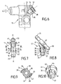
- the figure 6 shows a part of an injector 15 of the type equipping an internal combustion engine.
- This injector 15 has a radial inlet 4 of fuel under high pressure and it is provided with a bore 16 adapted to receive a quick coupling 17 according to the invention as shown in FIGS. Figures 7 and 8 .
- the bore 16 is made in a tubing 18 at a rear end of the injector 15 and is in communication with the interior thereof.
- the connector 17, which in the example illustrated is a T-piece, comprises a generally cylindrical hollow body 19 having, at a rear end, connecting means 20, 21 making it possible to connect the coupling to a fuel return pipe (not shown). ).
- the body 19 has at a front end a tubular nozzle 22 provided with sealing means in the form of an O-ring seal 9.
- the nozzle 22 is adapted to be received in a housing 23 at the bottom of the bore 16 (see figure 12 ).
- the body 19 carries retaining means of the endpiece 22 in the housing 23.
- these retaining means comprise two elastic tongues 24, 25 in an arc extending substantially concentrically to the axis AA of the body.
- Each of the elastic tabs 24, 25 defines with the periphery of the body 19 a slot in a circular arc 26, 27 and carries at its free end a fastening member in the form of a protrusion 28, 29.
- Each of the resilient tongues 24, 25 is connected to the body 19 by means of a radial rib 30, 31 on the body to move the respective tongue outwards so that the thickness of the corresponding slot 26, 27 corresponds to substantially at the thickness of the protrusion 28, 29.
- the rib 30 of the first tongue 24 is disposed diametrically opposite the rib 31 of the second tongue 25.
- the protuberances 28, 29 are capable of penetrating into a groove 32 formed in the rear part of the bore 16 and can, when the endpiece 22 of the coupling 17 is inserted into the bore 16, retract elastically towards the fitting body 19 to then extend in the groove 32 thanks to the elastic return of the tongues 24, 25.
- the protuberances 28, 29 advantageously have an inclined bottom surface 33 forming a ramp, coming into contact with the edge around the opening of the bore 16 which in the same way may comprise an inclined annular surface 34 of the same angle to better cooperate with the lower surface 33.
- the protuberances 28, 29 advantageously also have an inclined upper surface 35 forming a ramp in contact with an inclined surface 36 of the same angle in the upper part of the throat 32.
- the protuberances 28, 29 may simply have a section of a circle in section and in this case, the inclined surfaces 34 and 36 are no longer indispensable. It is sufficient, in fact, to provide a curved profile in one way or another to the outside.
- the connector 17 further comprises a flange 37 disposed on the periphery of the body 19 immediately after the tongues 24, 25 so as to delimit the bending thereof forward during the removal of the tip 22 from the bore 16.
- the flange 37 also serves as abutment while bearing against a circular shoulder 38 delimiting the groove 32 in the bore 16 downwards.
- the location of the collar 37 with respect to the shoulder 38 is such that it determines the insertion length of the body 29 in the bore 16.
- the tongues 24, 25 are sized to protrude out of the bore 16 when the tip is in its housing 23 in the bore to allow their radial compression during disassembly of the connector 17.
- the cylindrical body 19, the connecting means 20, 21, the tabs 24, 25, the ribs 30, 31 and the collar 37 are made of material, for example by injection molding of an elastic material such as polyamide .
- the connector 17 further comprises interlocking locking members 39, 40 of the tongues 24, 25.
- These locking members 39, 40 have an arcuate shape and they are able to be inserted in a respective slot 26, 27 after the insertion of the nozzle 22 in the bore 16 to connect the connector 17 to the injector 15. In this way, the protuberances 28, 29 can not leave the groove 32 and the tongues are thus locked inside the bore 16.
- the locking members 39, 40 are advantageously connected to the underside of a ring 41 slidably mounted on the body 19.
- the locking members 39, 40 define between them notches 42, 43 open downwards and able to receive the ribs 30, 31 during the introduction of the locking members in the slots 26, 27.
- the locking members Preferably, the locking members completely fill the slots 26, 27 extending from one rib (30 or 31) to the next .
- the locking members 39, 40 thus constitute with the ring 41 an assembly having the general shape of a flanged sleeve which is advantageously manufactured in one piece, also in elastic material.
- the ring is split (44) up to one (42) of the notches. This allows its mounting on the body 19 by the side.
- FIG. figure 7 shows the locking members 39, 40 removed from the slots. It is then sufficient to introduce the nozzle 22 of the connector in the bore 16 until the protuberances 28, 29 come into contact with the edge of the bore and then push so that the tongues 24, 25 are thus elastically pushed radially. towards the inside. This insertion movement is continued until the flange 37 comes into abutment against the circular shoulder 38 of the bore, while simultaneously, the protuberances 28, 29 are housed in the groove 32 so as to retain the connection in this position.
- the tongues 24, 25 take the form indicated in FIG. figure 9 and it is then possible to move the locking members 39, 40 downwards by pushing on the ring 41 so that these organs enter the slots 26, 27 so as to completely lock the tabs inside the bore 16.
- the locking members 39, 40 thus provide a double security and there is no risk that the connection can be unintentionally released.
- Uninstalling connector 17 is also very simple.
- the locking members 39, 40 are first moved outwards by pulling on the ring 41 and then, because the tongues 24, 25 project out of the bore 16, they can be pinched to remove the protuberances 28. , 29 of the groove 32 of the bore and from this moment remove the assembly of the connection without problem.
Landscapes
- Engineering & Computer Science (AREA)
- General Engineering & Computer Science (AREA)
- Mechanical Engineering (AREA)
- Chemical & Material Sciences (AREA)
- Combustion & Propulsion (AREA)
- Quick-Acting Or Multi-Walled Pipe Joints (AREA)
- Fuel-Injection Apparatus (AREA)
- Media Introduction/Drainage Providing Device (AREA)
- Containers And Packaging Bodies Having A Special Means To Remove Contents (AREA)
- Compositions Of Oxide Ceramics (AREA)
Abstract
Description
La présente invention concerne un raccord à accouplement rapide, en particulier un raccord utilisé dans un système d'alimentation en carburant comportant plusieurs injecteurs alimentant un moteur à combustion interne, notamment un moteur diesel.The present invention relates to a quick-coupling coupling, in particular a connector used in a fuel supply system comprising a plurality of injectors feeding an internal combustion engine, in particular a diesel engine.
Un raccord de ce genre est associé à chaque injecteur et a pour fonction de le relier à un conduit de retour de carburant vers un réservoir de carburant. Les injecteurs sont alimentés à l'aide d'une pompe à haute pression et le retour de carburant est en effet relativement important. Cette utilisation d'un raccord à accouplement rapide sur un injecteur de carburant est bien connue en soi et ne sera pas expliquée plus en détail.A connector of this type is associated with each injector and has the function of connecting it to a fuel return duct to a fuel tank. The injectors are powered by a high pressure pump and fuel return is indeed relatively important. This use of a quick coupling on a fuel injector is well known per se and will not be explained in more detail.
Cependant, on connaît plusieurs types de tels raccords à accouplement rapide qui sont tous pourvus de moyens de liaison à un conduit de retour de carburant, d'un embout tubulaire pouvant être introduit dans un perçage effectué dans un injecteur pour former une sortie de carburant de retour, et de moyens de retenue de l'embout dans ce perçage.However, several types of such quick coupling couplings are known, all of which are provided with means for connection to a fuel return conduit, a tubular nozzle that can be inserted into a bore made in an injector to form a fuel outlet. return, and retaining means of the nozzle in this piercing.
Les
Les
Le raccord 1 comporte un corps creux cylindrique 5 qui à une extrémité arrière présente des moyens de liaison 6, 7 à un conduit de retour de carburant (non représenté sur les figures).The
A une extrémité avant, le raccord 1 comporte un embout tubulaire 8 portant des moyens d'étanchéité sous forme d'un joint torique d'étanchéité 9. Cet embout tubulaire 8 peut être reçu dans un perçage 10 de l'injecteur 2 pour reposer dans un logement 11 au fond du perçage en communication avec l'intérieur de l'injecteur afin de recevoir le carburant de retour.At a front end, the
Le corps 5 du raccord 1 porte des moyens de retenue de l'embout tubulaire 8 dans le logement 11. Ces moyens de retenue comportent un cadre 12 portant deux bras élastiques 13 constituant des prolongements du cadre vers l'avant.The
Le cadre 12 est globalement rectangulaire et enserre à l'extrémité arrière les moyens de liaison 6, 7 et à l'extrémité avant l'embout 8. Le côté du cadre 12 qui enserre l'embout 8 présente une forme incurvée adaptée à la surface extérieure de l'injecteur 2 pour venir se plaquer contre celle-ci lorsque l'embout est inséré dans le perçage 10.The
Les deux bras élastiques 13 s'étendent de part et d'autre de l'embout 8 sensiblement parallèlement l'un à l'autre pour venir s'encliqueter sur l'injecteur 2 lorsque l'embout 8 est introduit dans le perçage 10. Pour améliorer la prise des bras 13 sur l'injecteur 2, celui-ci présente sur sa périphérie deux méplats 14 parallèles l'un à l'autre contre lesquels les bras peuvent reposer et les extrémités de ceux-ci sont déviées l'une vers l'autre de manière à venir en appui contre la face extérieure de l'injecteur et ainsi retenir le raccord en position contre celui-ci.The two
Le raccord à accouplement rapide 1 qui vient d'être décrit est cependant très limité dans son utilisation puisqu'il suppose que le perçage 10 est perpendiculaire à l'axe de l'injecteur 2 et qu'il y a suffisamment de place derrière celui-ci pour laisser passer les bras 13 pour leur encliquetage.The quick-
Autrement dit, il est impossible d'utiliser ce raccord lorsqu'on souhaite, par exemple à cause de l'environnement moteur, placer le raccord sous un certain angle dans un ou plusieurs plans simultanément comme cela est illustré par les angles α1 et α2 montrés sur les
On connaît également d'autres raccords à accouplement rapide comme illustré dans le document
Le but de l'invention est de proposer un raccord à accouplement rapide qui permet son installation sous pratiquement n'importe quel angle par rapport à l'axe de l'injecteur, qui est simple à fabriquer et qui peut facilement être installé et désinstallé. En outre, ce raccord comporte selon un des modes de réalisation une double sécurité évitant toute fuite de carburant provoquée par une libération intempestive des moyens de retenue.The object of the invention is to provide a quick-coupling coupling which allows its installation at virtually any angle with respect to the axis of the injector, which is simple to manufacture and which can easily be installed and uninstalled. In addition, this connection comprises, according to one embodiment, a double safety avoiding any fuel leakage caused by an untimely release of the retaining means.
L'objet de l'invention est un raccord à accouplement rapide apte à relier un injecteur d'un moteur à combustion interne à un conduit de retour de carburant, comportant un corps creux globalement cylindrique présentant à une extrémité arrière des moyens de liaison audit conduit de retour de carburant, et à une extrémité avant un embout tubulaire portant des moyens d'étanchéité et apte à être reçu dans un logement formé dans un perçage sur la périphérie dudit injecteur en communication avec l'intérieur de celui-ci, ledit corps portant des moyens de retenue dudit embout tubulaire dans ledit logement, caractérisé en ce que lesdits moyens de retenue comportent deux languettes élastiques en arc de cercle s'étendant sur la périphérie dudit corps sensiblement concentriquement à l'axe de celui-ci, chacune desdites languettes définissant avec la périphérie dudit corps une fente en arc de cercle ouverte d'un côté, et en ce que lesdites languettes sont aptes à coopérer avec une gorge prévue à l'intérieur dudit perçage de l'injecteur.The object of the invention is a quick-coupling coupling adapted to connect an injector of an internal combustion engine to a fuel return conduit, comprising a generally cylindrical hollow body having, at a rear end, means of connection to said conduit. fuel return, and at a front end a tubular nozzle carrying sealing means and adapted to be received in a housing formed in a bore on the periphery of said injector in communication with the interior thereof, said bearing body retaining means for said tubular nozzle in said housing, characterized in that said retaining means comprise two elastic tongues in an arc extending circumferentially around said body substantially concentrically with the axis thereof, each of said tongues defining with the periphery of said body an arcuate slot open on one side, and in that said tabs are adapted to ooperate with a groove provided inside said piercing of the injector.
Selon d'autres caractéristiques de l'invention :
- lesdites languettes portent à une extrémité libre un organe d'accrochage sous forme d'une protubérance apte à pénétrer dans ladite gorge ;
- une extrémité fixe de chaque languette est reliée audit corps par l'intermédiaire d'une nervure radiale sur ledit corps ;
- ladite nervure radiale d'une première languette est disposée diamétralement opposée à la nervure d'une deuxième languette ;
- l'épaisseur de ladite protubérance correspond sensiblement à l'épaisseur de ladite fente ;
- adite protubérance présente un profil bombé vers l'extérieur ;
- lesdites languettes sont dimensionnées pour faire saillie hors dudit perçage lorsque ledit embout est inséré dans celui-ci ;
- la flexion desdites languettes vers l'avant est délimitée par un collet sur la périphérie dudit corps ;
- ledit collet est apte à servir de butée contre un épaulement circulaire dans ledit perçage lors de l'introduction dudit embout dans celui-ci ;
- ledit corps, lesdits moyens de liaison, lesdites languettes, lesdites nervures et ledit collet sont venus de matière ;
- ledit raccord comporte en outre des organes intercalaires de blocage des languettes, ces organes de blocage présentant une forme en arc de cercle et étant aptes à être insérés dans une fente respective desdites fentes, suite à l'introduction dudit embout dans ledit perçage ;
- lesdits organes de blocage sont reliés à la face inférieure d'un anneau monté coulissant sur ledit corps ;
- lesdits organes de blocage définissent entre eux des évidements ouverts vers le bas et aptes à recevoir lesdites nervures lors de l'introduction desdits organes de blocage dans lesdites fentes ;
- ledit anneau est en un matériau élastique et est fendu afin de permettre son montage sur ledit corps par le côté ;
- lesdits organes de blocage s'étendent dans lesdites fentes et jusqu'à la languette suivante.
- said tabs carry at one free end a hooking member in the form of a protuberance adapted to penetrate into said groove;
- a fixed end of each tongue is connected to said body via a radial rib on said body;
- said radial rib of a first tongue is disposed diametrically opposite the rib of a second tongue;
- the thickness of said protuberance substantially corresponds to the thickness of said slot;
- adite protuberance has a curved profile to the outside;
- said tongues are sized to protrude out of said bore when said tip is inserted therein;
- the flexing of said tongues towards the front is delimited by a collar on the periphery of said body;
- said collar is adapted to serve as a stop against a circular shoulder in said bore during the introduction of said tip therein;
- said body, said connecting means, said tabs, said ribs and said collar are integral;
- said fitting further comprises intermediate tab locking members, these locking members having an arcuate shape and being able to be inserted into a respective slot of said slots, following the introduction of said tip into said bore;
- said locking members are connected to the lower face of a ring slidably mounted on said body;
- said locking members define between them recesses open downwards and adapted to receive said ribs during the introduction of said locking members in said slots;
- said ring is of an elastic material and is split to allow its mounting on said body by the side;
- said locking members extend in said slots and up to the next tab.
L'invention concerne également un raccord à accouplement rapide défini ci-dessus, caractérisé par le fait qu'il est associé à un raccord présentant les caractéristiques mentionnées ci-dessus, et par le fait qu'il est adapté pour coopérer avec des moyens de retenue prévus sur le raccord.The invention also relates to a quick coupling coupling defined above, characterized in that it is associated with a coupling having the characteristics mentioned above, and in that it is adapted to cooperate with means of restraint provided on the fitting.
D'autres caractéristiques et avantages de l'invention ressortiront de la description qui va suivre d'un mode de réalisation non limitatif de l'invention, en référence aux figures annexées dans lesquelles :
- les
figures 1 et 2 montrent une vue latérale, partiellement en coupe, respectivement une vue de dessus d'un injecteur conçu pour recevoir un raccord à accouplement rapide connu ; - les
figures 3 et 4 montrent une vue latérale respectivement une vue de dessus, d'un raccord à accouplement connu apte à être monté sur l'inj ecteur illustré auxfigures 1 et 2 ; - la
figure 5 montre schématiquement dans une vue de dessus le raccord desfigures 3 et 4 monté sur l'injecteur desfigures 1 et 2 ; - la
figure 6 montre une vue partielle, partiellement en coupe, d'un injecteur apte à recevoir un raccord à accouplement rapide selon l'invention ; - la
figure 7 est une vue latérale, partiellement en coupe, d'un raccord à accouplement rapide selon l'invention ; - la
figure 8 est une vue en perspective du raccord de lafigure 7 ; - la
figure 9 est une vue en coupe selon la ligne IX-IX de lafigure 7 ; - la
figure 10 est une vue en perspective de moyens intercalaires de blocage selon l'invention ; - la
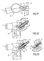
figure 11 est une vue de dessus du raccord desfigures 7 monté sur l'injecteur de laet 8figure 6 ; - la
figure 12 est une vue latérale, partiellement en coupe, montrant la position des moyens intercalaires de blocage de lafigure 10 avant leur insertion dans le perçage de l'injecteur ; et - la
figure 13 est une vue latérale, partiellement en coupe, montrant la position des moyens intercalaires de blocage de lafigure 10 après leur insertion dans le perçage de l'injecteur. Une partie de lafigure 13 a été rendue en plus grande échelle pour mieux montrer les détails.
- the
Figures 1 and 2 show a side view, partially in section, respectively a top view of an injector adapted to receive a known quick coupling coupling; - the
Figures 3 and 4 show a side view respectively a view from above, of a known coupling coupling adapted to be mounted on the inj ector illustrated in FIGS.Figures 1 and 2 ; - the
figure 5 schematically shows in a view from above the connection ofFigures 3 and 4 mounted on the injectorFigures 1 and 2 ; - the
figure 6 shows a partial view, partially in section, an injector adapted to receive a quick-coupling coupling according to the invention; - the
figure 7 is a side view, partially in section, of a quick-coupling coupling according to the invention; - the
figure 8 is a perspective view of the fitting of thefigure 7 ; - the
figure 9 is a sectional view along the line IX-IX of thefigure 7 ; - the
figure 10 is a perspective view of intermediate blocking means according to the invention; - the
figure 11 is a top view of the connection of theFigures 7 and 8 mounted on the injector of thefigure 6 ; - the
figure 12 is a side view, partly in section, showing the position of the interposed locking means of thefigure 10 before insertion into the piercing of the injector; and - the
figure 13 is a side view, partly in section, showing the position of the interposed locking means of thefigure 10 after their insertion into the piercing of the injector. A part of thefigure 13 has been made on a larger scale to better show the details.
La
Le raccord 17, qui dans l'exemple illustré est un raccord en T, comporte un corps creux globalement cylindrique 19 présentant à une extrémité arrière des moyens de liaison 20, 21 permettant de relier le raccord à un conduit de retour de carburant (non représenté).The
Le corps 19 présente à une extrémité avant un embout tubulaire 22 pourvu de moyens d'étanchéité sous forme d'un joint torique d'étanchéité 9. L'embout 22 est apte à être reçu dans un logement 23 au fond du perçage 16 (voir
Le corps 19 porte des moyens de retenue de l'embout 22 dans le logement 23. Selon l'invention, ces moyens de retenue comportent deux languettes élastiques 24, 25 en arc de cercle s'étendant sensiblement concentriquement à l'axe A-A du corps.The
Chacune des languettes élastiques 24, 25 définit avec la périphérie du corps 19 une fente en arc de cercle 26, 27 et porte à son extrémité libre un organe d'accrochage sous forme d'une protubérance 28, 29.Each of the
Chacune des languettes élastiques 24, 25 est reliée au corps 19 par l'intermédiaire d'une nervure radiale 30, 31 sur le corps pour déporter la languette respective vers l'extérieur de sorte que l'épaisseur de la fente correspondante 26, 27 corresponde sensiblement à l'épaisseur de la protubérance 28, 29. La nervure 30 de la première languette 24 est disposée diamétralement opposée à la nervure 31 de la deuxième languette 25.Each of the
Les protubérances 28, 29 sont aptes à pénétrer dans une gorge 32 formée dans la partie arrière du perçage 16 et peuvent lors de l'introduction de l'embout 22 du raccord 17 dans le perçage 16 s'escamoter élastiquement vers le corps 19 du raccord pour ensuite s'étendre dans la gorge 32 grâce au rappel élastique des languettes 24, 25.The
Afin de faciliter l'introduction des languettes 24, 25 dans le perçage 16 de la tubulure 18 de l'injecteur 15, les protubérances 28, 29 présentent avantageusement une surface inférieure inclinée 33 formant rampe en venant en contact avec le bord autour de l'ouverture du perçage 16 qui de la même manière peut comporter une surface annulaire inclinée 34 du même angle pour mieux coopérer avec la surface inférieure 33. Ces détails sont au mieux représentés dans l'agrandissement d'une partie de la
Afin de faciliter le retrait des languettes 24, 25 du perçage 16 de la tubulure 18 de l'injecteur 15, les protubérances 28, 29 présentent avantageusement en outre une surface supérieure inclinée 35 formant rampe en contact avec une surface inclinée 36 du même angle prévue dans la partie supérieure de la gorge 32.In order to facilitate removal of the
Selon une variante non représentée sur les figures, les protubérances 28, 29 peuvent tout simplement présenter en coupe un segment de cercle et dans ce cas, les surfaces inclinées 34 et 36 ne sont plus indispensables. Il suffit, en effet, de prévoir un profil bombé d'une manière ou d'une autre vers l'extérieur.According to a variant not shown in the figures, the
Le raccord 17 comporte en outre un collet 37 disposé sur la périphérie du corps 19 immédiatement après les languettes 24, 25 de manière à délimiter la flexion de celles-ci vers l'avant lors du retrait de l'embout 22 du perçage 16.The
Le collet 37 sert également de butée en venant en appui contre un épaulement circulaire 38 délimitant la gorge 32 dans le perçage 16 vers le bas. L'emplacement du collet 37 par rapport à l'épaulement 38 est tel qu'il détermine la longueur d'introduction du corps 29 dans le perçage 16.The
Par ailleurs, les languettes 24, 25 sont dimensionnées pour faire saillie hors du perçage 16 lorsque l'embout se trouve dans son logement 23 dans le perçage pour permettre leur compression radiale lors du démontage du raccord 17.Moreover, the
Avantageusement, le corps cylindrique 19, les moyens de liaison 20, 21, les languettes 24, 25, les nervures 30, 31 et le collet 37 sont venus de matière, par exemple par moulage à injection d'une matière élastique telle que le polyamide.Advantageously, the
Dans l'exemple illustré sur les figures, le raccord 17 comporte en outre des organes intercalaires de blocage 39, 40 des languettes 24, 25. Ces organes de blocage 39, 40 présentent une forme en arc de cercle et ils sont aptes à être insérés dans une fente respective 26, 27 après l'introduction de l'embout 22 dans le perçage 16 pour relier le raccord 17 à l'injecteur 15. De cette manière, les protubérances 28, 29 ne peuvent plus sortir de la gorge 32 et les languettes sont ainsi bloquées à l'intérieur du perçage 16.In the example illustrated in the figures, the
Les organes de blocage 39, 40 sont avantageusement reliés à la face inférieure d'un anneau 41 monté coulissant sur le corps 19. Les organes de blocage 39, 40 définissent entre eux des encoches 42, 43 ouvertes vers le bas et aptes à recevoir les nervures 30, 31 lors de l'introduction des organes de blocage dans les fentes 26, 27. De préférence, les organes de blocage remplissent entièrement les fentes 26, 27 en s'étendant d'une nervure (30 ou 31) à la suivante.The locking
Les organes de blocage 39, 40 constituent ainsi avec l'anneau 41 un ensemble ayant la forme générale d'un manchon à bride qui est avantageusement fabriqué en une seule pièce, aussi en matière élastique. Pour le montage sur le corps 19 de cet ensemble, l'anneau est fendu (44) jusqu'à une (42) des encoches. Cela permet son montage sur le corps 19 par le côté.The locking
L'installation du raccord à accouplement rapide 17 sur l'injecteur 15 est particulièrement facile à partir de son état représenté à la
En même temps, les languettes 24, 25 reprennent la forme indiquée à la
La désinstallation du raccord 17 est également très simple. On commence par déplacer les organes de blocage 39, 40 vers l'extérieur en tirant sur l'anneau 41 et ensuite, grâce au fait que les languettes 24, 25 font saillie hors du perçage 16, on peut les pincer pour sortir les protubérances 28, 29 de la gorge 32 du perçage et à partir de ce moment retirer l'ensemble du raccord sans problème.Uninstalling
Bien entendu, l'invention n'est pas limitée au mode de réalisation illustré et décrit, puisqu'un grand nombre de modifications peuvent être apportées par l'homme du métier sans pour autant sortir du cadre de l'invention.Of course, the invention is not limited to the embodiment illustrated and described, since a large number of modifications can be made by those skilled in the art without departing from the scope of the invention.
Claims (16)
- Quick-coupling joint able to connect an injector (15) of an internal combustion engine to a fuel return pipe, including a generally cylindrical hollow body (19) presenting at a rear end means for connection (20, 21) to the said fuel return pipe, and at a front end a tubular nozzle (22) carrying sealing means (9) and able to be received in a housing (23) formed in a bore (16) on the periphery of the said injector (15) in communication with the inside of the latter, the said body (19) carrying means (24, 25) for retaining the said tubular nozzle in the said housing (23), characterised by the fact that the said retaining means (24, 25) include two elastic tongues in an arc of circle extending on the periphery of the said body (19) substantially concentrically with the axis A-A of the latter, each of the said tongues (24, 25) defining with the periphery of the said body (19) a slot in an arc of circle (26, 27) open on one side, and by the fact that the said tongues (24, 25) are able to co-operate with a groove (32) provided inside the said bore (16) of the injector (15), the joint also including intercalary organs (39, 40) for locking the tongues (24, 25) able to be inserted in a respective slot of the said slots (26, 27), following introduction of the said nozzle (22) into the said bore (16).
- Quick-coupling joint as described in claim 1, characterised by the fact that the said tongues (24, 25) carry at a free end a catching organ in the form of a protuberance (28, 29) able to enter the said groove (32).
- Quick-coupling joint as described in claim 1 or 2, characterised by the fact that a fixed end of each tongue (24, 25) is joined to the said body (19) by means of a radial flange (30, 31) on the said body (19).
- Quick-coupling joint as described in claim 3, characterised by the fact that the said radial flange (30) of a first tongue (24) is arranged diametrically opposite to the flange (31) of a second tongue (25).
- Quick-coupling joint as described in any one of claims 2 to 4, characterised by the fact that the thickness of the said protuberance (28, 29) substantially corresponds to the thickness of the said slot (26, 27).
- Quick-coupling joint as described in any one of claims 3 to 5, characterised by the fact that the said protuberance (28, 29) presents an outwardly convex shape.
- Quick-coupling joint as described in any one of the preceding claims, characterised by the fact that the said tongues (24, 25) are dimensioned so as to project from the said bore (16) when the said nozzle (22) is inserted in it.
- Quick-coupling joint as described in any one of the preceding claims, characterised by the fact that the flexing of the said tongues (24, 25) towards the front is delimited by a collar (37) on the periphery of the said body (19).
- Quick-coupling joint as described in claim 8, characterised by the fact that the said collar (37) is able to act as a stop against a circular shoulder (38) in the said bore (19) on introduction of the said nozzle (22) into it.
- Quick-coupling joint as described in claim 8 or 9, characterised by the fact that the said body (19), the said connection means (20, 21), the said tongues (24, 25), the said flanges (30, 31) and the said collar (37) are made in one piece.
- Quick-coupling joint as described in one of the preceding claims, characterised by the fact that the said locking organs have the shape of an arc of circle.
- Quick-coupling joint as described in claim 11, characterised by the fact that the said locking organs (39, 40) are joined to the lower face of a ring (41) mounted slidingly on the said body (19).
- Quick-coupling joint as described in claim 12, characterised by the fact that the said locking organs (39, 40) define between them downwardly open cavities (30, 31) able to receive the said flanges (30, 31) on introduction of the said locking organs 39, 40) into the said slots (26, 27).
- Quick-coupling joint as described in claim 12 or 13, characterised by the fact that the said ring (41) is made of an elastic material and is split (44) to allow it to be mounted on the said body (19) from the side.
- Quick-coupling joint as described in any one of claims 11 to 14, characterised by the fact that the said locking organs (39, 40) extend in the said slots (26, 27) and up to the next tongue (24, 25).
- Injector for internal combustion engine, characterised by the fact that it is associated with a joint (17) as described in any one of claims 1 to 15 and by the fact that it is suitable to co-operate with retaining means (24, 25) provided on the said joint.
Priority Applications (6)
| Application Number | Priority Date | Filing Date | Title |
|---|---|---|---|
| AT06291313T ATE408752T1 (en) | 2006-08-16 | 2006-08-16 | QUICK COUPLING |
| DE602006002823T DE602006002823D1 (en) | 2006-08-16 | 2006-08-16 | quick coupling |
| EP06291313A EP1890030B1 (en) | 2006-08-16 | 2006-08-16 | Quick connect coupling |
| US12/377,272 US20110095522A1 (en) | 2006-08-16 | 2007-08-10 | Quick connection union |
| JP2009524219A JP2010500505A (en) | 2006-08-16 | 2007-08-10 | Quick coupling connector |
| PCT/FR2007/051810 WO2008020145A2 (en) | 2006-08-16 | 2007-08-10 | Quick-coupling connector |
Applications Claiming Priority (1)
| Application Number | Priority Date | Filing Date | Title |
|---|---|---|---|
| EP06291313A EP1890030B1 (en) | 2006-08-16 | 2006-08-16 | Quick connect coupling |
Publications (2)
| Publication Number | Publication Date |
|---|---|
| EP1890030A1 EP1890030A1 (en) | 2008-02-20 |
| EP1890030B1 true EP1890030B1 (en) | 2008-09-17 |
Family
ID=37697979
Family Applications (1)
| Application Number | Title | Priority Date | Filing Date |
|---|---|---|---|
| EP06291313A Not-in-force EP1890030B1 (en) | 2006-08-16 | 2006-08-16 | Quick connect coupling |
Country Status (6)
| Country | Link |
|---|---|
| US (1) | US20110095522A1 (en) |
| EP (1) | EP1890030B1 (en) |
| JP (1) | JP2010500505A (en) |
| AT (1) | ATE408752T1 (en) |
| DE (1) | DE602006002823D1 (en) |
| WO (1) | WO2008020145A2 (en) |
Families Citing this family (6)
| Publication number | Priority date | Publication date | Assignee | Title |
|---|---|---|---|---|
| GB2467321A (en) * | 2009-01-28 | 2010-08-04 | Fluid Transfer Systems Ltd | Snap-fit connector and non-return valve for a fuel injector leak-off line |
| GB2469119B (en) * | 2009-04-03 | 2013-07-03 | Managed Pressure Operations | Drill pipe connector |
| DE102010022304A1 (en) * | 2010-06-01 | 2011-12-01 | Veritas Ag | Quick coupling for fluid lines |
| RU2461762C1 (en) * | 2011-07-27 | 2012-09-20 | Открытое акционерное общество "Центральное конструкторское бюро машиностроения" | Connection device |
| ITTO20120090A1 (en) * | 2012-02-03 | 2013-08-04 | Eltek Spa | DEVICE AND / OR DUCT FOR DETECTION OF FUEL SUPPLIED TO AN INTERNAL COMBUSTION ENGINE |
| EP4112914A1 (en) * | 2021-06-29 | 2023-01-04 | Volvo Truck Corporation | Fuel conduit connection assembly for a vehicle |
Family Cites Families (16)
| Publication number | Priority date | Publication date | Assignee | Title |
|---|---|---|---|---|
| US3245703A (en) * | 1963-10-28 | 1966-04-12 | Robert S Manly | Quick detachable pipe coupling |
| US4875711A (en) * | 1988-04-25 | 1989-10-24 | Usui Kokusai Sangyo Kaisha Ltd. | Slender tube connector |
| DE9114365U1 (en) * | 1991-11-18 | 1992-03-12 | Vorschepoth, Heinrich, 5000 Koeln, De | |
| WO1994023775A1 (en) * | 1993-03-23 | 1994-10-27 | Abbott Laboratories | Securing collar for cannula connector |
| US6068303A (en) * | 1995-09-13 | 2000-05-30 | Hollnagle; Harold E. | Tube for connection to female socket |
| US5806898A (en) * | 1996-11-21 | 1998-09-15 | Hollnagle; Harold E. | Tube quick connect coupling |
| DE19755826C1 (en) * | 1997-12-16 | 1999-05-20 | Raymond A & Cie | Releasable connector for pressure hoses |
| DE19940387C1 (en) * | 1999-08-25 | 2001-02-22 | Siemens Ag | Leakage connection for connecting leakage line to fuel injector of internal combustion engine is cost-effective to produce and enables simple and reliable installation |
| US6749233B2 (en) * | 2000-06-08 | 2004-06-15 | Hitachi Metals, Ltd. | Sleeve-type pipe joint |
| JP2003028031A (en) * | 2001-07-16 | 2003-01-29 | Daihatsu Motor Co Ltd | Installation device for fuel injection valve in multicylinder internal combustion engine |
| DE20319558U1 (en) * | 2003-12-17 | 2005-04-28 | Voss Automotive Gmbh | Plug-in and lockable cable connector |
| EP1662132A3 (en) * | 2004-11-25 | 2006-06-07 | Itt Manufacturing Enterprises, Inc. | Device to attach a fuel return line to a fuel injector and device to suction fuel from a fuel injector |
| DE202005015966U1 (en) * | 2005-10-10 | 2007-02-15 | Voss Automotive Gmbh | Connectors for media cables |
| JP4929864B2 (en) * | 2006-06-15 | 2012-05-09 | 株式会社デンソー | Piping joint device |
| JP4670748B2 (en) * | 2006-06-16 | 2011-04-13 | 日産自動車株式会社 | Fuel supply system |
| US7658420B2 (en) * | 2006-07-13 | 2010-02-09 | Parker-Hannifin Corporation | Quick-connect fitting with unlocking ring |
-
2006
- 2006-08-16 AT AT06291313T patent/ATE408752T1/en not_active IP Right Cessation
- 2006-08-16 EP EP06291313A patent/EP1890030B1/en not_active Not-in-force
- 2006-08-16 DE DE602006002823T patent/DE602006002823D1/en active Active
-
2007
- 2007-08-10 JP JP2009524219A patent/JP2010500505A/en not_active Ceased
- 2007-08-10 WO PCT/FR2007/051810 patent/WO2008020145A2/en active Application Filing
- 2007-08-10 US US12/377,272 patent/US20110095522A1/en not_active Abandoned
Also Published As
| Publication number | Publication date |
|---|---|
| DE602006002823D1 (en) | 2008-10-30 |
| EP1890030A1 (en) | 2008-02-20 |
| US20110095522A1 (en) | 2011-04-28 |
| WO2008020145A3 (en) | 2008-04-10 |
| ATE408752T1 (en) | 2008-10-15 |
| JP2010500505A (en) | 2010-01-07 |
| WO2008020145A2 (en) | 2008-02-21 |
Similar Documents
| Publication | Publication Date | Title |
|---|---|---|
| EP2878873B1 (en) | Cartridge-type quick-coupling device | |
| EP2251581B1 (en) | Snap coupling between a fluid pipe and a rigid connecting piece with a device for verifying the connection and method for verifying said connection | |
| EP1890030B1 (en) | Quick connect coupling | |
| EP1440271B1 (en) | Coupler | |
| FR2901595A1 (en) | Connector`s male element for detachable junction of two pipelines, has protection groove whose notch locks pins with respect to locking ring in notch of locking ring, where notch of locking ring is oriented with respect to female element | |
| EP1780427B1 (en) | Not drastic anchorage disk | |
| FR2899308A1 (en) | Quick pipe connector for use in engine coolant system, has pair of retainers resiliently deformable in manner such that free ends spread out with fixing end portions by pressing pair of release arms radially inward | |
| FR2942862A1 (en) | CONNECTION DEVICE FOR TRANSFER OF FLUID, INCORPORATING CIRCUIT AND METHOD OF MOUNTING / DISASSEMBLING THE SAME. | |
| FR2930904A1 (en) | FAST COUPLING ASSEMBLY AND CLEARING TOOL | |
| FR2669709A1 (en) | CONNECTION DEVICE, PARTICULARLY FOR ASSEMBLING A HOSE TO A MOTOR VEHICLE HEAT EXCHANGER. | |
| EP1807648B1 (en) | Segmented locking ring, and corresponding assembly and mounting method | |
| EP1258666B1 (en) | Quick connector with fastening by elastic external ring | |
| FR2891889A1 (en) | End piece for sealed connect coupling, has rear edge presenting female configuration comprising annular groove and annular protection wall extending towards rear from outer edge of annular groove | |
| EP2425170B1 (en) | System for attaching a connector for a fluid transport pipe on a wall | |
| FR2795156A1 (en) | Snap-on connector with adjustable sleeve used on motor vehicle for fuel line has rigid tubular end piece fitting into end of fuel line and sealed into end of connector piece | |
| FR2910954A1 (en) | FLUID CONDUIT CONNECTOR EQUIPPED WITH A CLAMPING ARM | |
| EP1972846B1 (en) | Device for quick connection of a fluid conduit, in particular for an automobile with a male connection | |
| FR2883952A1 (en) | Rapid pipe connection, e.g. for air supply systems in supercharged car engines, comprises a male union, a gasket and a female union which is made in one piece with the associated fluid pipe as a monolithic body | |
| EP2101097B1 (en) | Connection device for fluid transfer, circuit including said device and assembly/disassembly method thereof | |
| EP1090247A1 (en) | Fast connecting end piece having a single-piece part comprising a locking ring and an additional ring | |
| EP4124788A1 (en) | Male element for fluid connector and fluid connector comprising such a male element | |
| FR2826428A1 (en) | Coupling between fuel line and connector on reserve tank comprises rib on line which fits at base into groove in flexible strip attached to connector, | |
| WO2009118417A1 (en) | Improved connector for medical use | |
| EP3855058B1 (en) | Tubular coupling device | |
| FR2628821A1 (en) | CONNECTING DEVICE |
Legal Events
| Date | Code | Title | Description |
|---|---|---|---|
| PUAI | Public reference made under article 153(3) epc to a published international application that has entered the european phase |
Free format text: ORIGINAL CODE: 0009012 |
|
| GRAP | Despatch of communication of intention to grant a patent |
Free format text: ORIGINAL CODE: EPIDOSNIGR1 |
|
| 17P | Request for examination filed |
Effective date: 20070507 |
|
| AK | Designated contracting states |
Kind code of ref document: A1 Designated state(s): AT BE BG CH CY CZ DE DK EE ES FI FR GB GR HU IE IS IT LI LT LU LV MC NL PL PT RO SE SI SK TR |
|
| AX | Request for extension of the european patent |
Extension state: AL BA HR MK YU |
|
| GRAS | Grant fee paid |
Free format text: ORIGINAL CODE: EPIDOSNIGR3 |
|
| GRAA | (expected) grant |
Free format text: ORIGINAL CODE: 0009210 |
|
| AK | Designated contracting states |
Kind code of ref document: B1 Designated state(s): AT BE BG CH CY CZ DE DK EE ES FI FR GB GR HU IE IS IT LI LT LU LV MC NL PL PT RO SE SI SK TR |
|
| REG | Reference to a national code |
Ref country code: GB Ref legal event code: FG4D Free format text: NOT ENGLISH |
|
| REG | Reference to a national code |
Ref country code: CH Ref legal event code: EP |
|
| REG | Reference to a national code |
Ref country code: IE Ref legal event code: FG4D Free format text: LANGUAGE OF EP DOCUMENT: FRENCH |
|
| AKX | Designation fees paid |
Designated state(s): AT BE BG CH CY CZ DE DK EE ES FI FR GB GR HU IE IS IT LI LT LU LV MC NL PL PT RO SE SI SK TR |
|
| REF | Corresponds to: |
Ref document number: 602006002823 Country of ref document: DE Date of ref document: 20081030 Kind code of ref document: P |
|
| PG25 | Lapsed in a contracting state [announced via postgrant information from national office to epo] |
Ref country code: LT Free format text: LAPSE BECAUSE OF FAILURE TO SUBMIT A TRANSLATION OF THE DESCRIPTION OR TO PAY THE FEE WITHIN THE PRESCRIBED TIME-LIMIT Effective date: 20080917 |
|
| PG25 | Lapsed in a contracting state [announced via postgrant information from national office to epo] |
Ref country code: SI Free format text: LAPSE BECAUSE OF FAILURE TO SUBMIT A TRANSLATION OF THE DESCRIPTION OR TO PAY THE FEE WITHIN THE PRESCRIBED TIME-LIMIT Effective date: 20080917 Ref country code: LV Free format text: LAPSE BECAUSE OF FAILURE TO SUBMIT A TRANSLATION OF THE DESCRIPTION OR TO PAY THE FEE WITHIN THE PRESCRIBED TIME-LIMIT Effective date: 20080917 Ref country code: AT Free format text: LAPSE BECAUSE OF FAILURE TO SUBMIT A TRANSLATION OF THE DESCRIPTION OR TO PAY THE FEE WITHIN THE PRESCRIBED TIME-LIMIT Effective date: 20080917 Ref country code: FI Free format text: LAPSE BECAUSE OF FAILURE TO SUBMIT A TRANSLATION OF THE DESCRIPTION OR TO PAY THE FEE WITHIN THE PRESCRIBED TIME-LIMIT Effective date: 20080917 |
|
| NLV1 | Nl: lapsed or annulled due to failure to fulfill the requirements of art. 29p and 29m of the patents act | ||
| REG | Reference to a national code |
Ref country code: IE Ref legal event code: FD4D |
|
| PG25 | Lapsed in a contracting state [announced via postgrant information from national office to epo] |
Ref country code: ES Free format text: LAPSE BECAUSE OF FAILURE TO SUBMIT A TRANSLATION OF THE DESCRIPTION OR TO PAY THE FEE WITHIN THE PRESCRIBED TIME-LIMIT Effective date: 20081228 Ref country code: BG Free format text: LAPSE BECAUSE OF FAILURE TO SUBMIT A TRANSLATION OF THE DESCRIPTION OR TO PAY THE FEE WITHIN THE PRESCRIBED TIME-LIMIT Effective date: 20081217 |
|
| PG25 | Lapsed in a contracting state [announced via postgrant information from national office to epo] |
Ref country code: IS Free format text: LAPSE BECAUSE OF FAILURE TO SUBMIT A TRANSLATION OF THE DESCRIPTION OR TO PAY THE FEE WITHIN THE PRESCRIBED TIME-LIMIT Effective date: 20090117 Ref country code: CZ Free format text: LAPSE BECAUSE OF FAILURE TO SUBMIT A TRANSLATION OF THE DESCRIPTION OR TO PAY THE FEE WITHIN THE PRESCRIBED TIME-LIMIT Effective date: 20080917 Ref country code: NL Free format text: LAPSE BECAUSE OF FAILURE TO SUBMIT A TRANSLATION OF THE DESCRIPTION OR TO PAY THE FEE WITHIN THE PRESCRIBED TIME-LIMIT Effective date: 20080917 Ref country code: PT Free format text: LAPSE BECAUSE OF FAILURE TO SUBMIT A TRANSLATION OF THE DESCRIPTION OR TO PAY THE FEE WITHIN THE PRESCRIBED TIME-LIMIT Effective date: 20090217 Ref country code: SK Free format text: LAPSE BECAUSE OF FAILURE TO SUBMIT A TRANSLATION OF THE DESCRIPTION OR TO PAY THE FEE WITHIN THE PRESCRIBED TIME-LIMIT Effective date: 20080917 Ref country code: RO Free format text: LAPSE BECAUSE OF FAILURE TO SUBMIT A TRANSLATION OF THE DESCRIPTION OR TO PAY THE FEE WITHIN THE PRESCRIBED TIME-LIMIT Effective date: 20080917 |
|
| PLBE | No opposition filed within time limit |
Free format text: ORIGINAL CODE: 0009261 |
|
| STAA | Information on the status of an ep patent application or granted ep patent |
Free format text: STATUS: NO OPPOSITION FILED WITHIN TIME LIMIT |
|
| PG25 | Lapsed in a contracting state [announced via postgrant information from national office to epo] |
Ref country code: EE Free format text: LAPSE BECAUSE OF FAILURE TO SUBMIT A TRANSLATION OF THE DESCRIPTION OR TO PAY THE FEE WITHIN THE PRESCRIBED TIME-LIMIT Effective date: 20080917 Ref country code: DK Free format text: LAPSE BECAUSE OF FAILURE TO SUBMIT A TRANSLATION OF THE DESCRIPTION OR TO PAY THE FEE WITHIN THE PRESCRIBED TIME-LIMIT Effective date: 20080917 Ref country code: IE Free format text: LAPSE BECAUSE OF FAILURE TO SUBMIT A TRANSLATION OF THE DESCRIPTION OR TO PAY THE FEE WITHIN THE PRESCRIBED TIME-LIMIT Effective date: 20080917 |
|
| 26N | No opposition filed |
Effective date: 20090618 |
|
| PG25 | Lapsed in a contracting state [announced via postgrant information from national office to epo] |
Ref country code: SE Free format text: LAPSE BECAUSE OF FAILURE TO SUBMIT A TRANSLATION OF THE DESCRIPTION OR TO PAY THE FEE WITHIN THE PRESCRIBED TIME-LIMIT Effective date: 20081217 |
|
| BERE | Be: lapsed |
Owner name: DELPHI TECHNOLOGIES, INC. Effective date: 20090831 |
|
| PG25 | Lapsed in a contracting state [announced via postgrant information from national office to epo] |
Ref country code: MC Free format text: LAPSE BECAUSE OF NON-PAYMENT OF DUE FEES Effective date: 20090831 |
|
| PG25 | Lapsed in a contracting state [announced via postgrant information from national office to epo] |
Ref country code: PL Free format text: LAPSE BECAUSE OF FAILURE TO SUBMIT A TRANSLATION OF THE DESCRIPTION OR TO PAY THE FEE WITHIN THE PRESCRIBED TIME-LIMIT Effective date: 20080917 |
|
| PG25 | Lapsed in a contracting state [announced via postgrant information from national office to epo] |
Ref country code: BE Free format text: LAPSE BECAUSE OF NON-PAYMENT OF DUE FEES Effective date: 20090831 |
|
| REG | Reference to a national code |
Ref country code: HU Ref legal event code: FH1C Free format text: FORMER REPRESENTATIVE(S): MESZAROSNE DONUSZ KATALIN, S.B.G. & K. SZABADALMI UEGYVIVOEI IRODA, HU Representative=s name: S.B.G. & K. SZABADALMI ES UEGYVEDI IRODAK, HU Ref country code: HU Ref legal event code: GB9C Owner name: DELPHI TECHNOLOGIES HOLDING S.A.R.L., LU Free format text: FORMER OWNER(S): DELPHI TECHNOLOGIES, INC., US |
|
| PG25 | Lapsed in a contracting state [announced via postgrant information from national office to epo] |
Ref country code: GR Free format text: LAPSE BECAUSE OF FAILURE TO SUBMIT A TRANSLATION OF THE DESCRIPTION OR TO PAY THE FEE WITHIN THE PRESCRIBED TIME-LIMIT Effective date: 20081218 |
|
| REG | Reference to a national code |
Ref country code: CH Ref legal event code: PL |
|
| REG | Reference to a national code |
Ref country code: FR Ref legal event code: TP |
|
| GBPC | Gb: european patent ceased through non-payment of renewal fee |
Effective date: 20100816 |
|
| PG25 | Lapsed in a contracting state [announced via postgrant information from national office to epo] |
Ref country code: CH Free format text: LAPSE BECAUSE OF NON-PAYMENT OF DUE FEES Effective date: 20100831 Ref country code: LU Free format text: LAPSE BECAUSE OF NON-PAYMENT OF DUE FEES Effective date: 20090816 Ref country code: LI Free format text: LAPSE BECAUSE OF NON-PAYMENT OF DUE FEES Effective date: 20100831 |
|
| PG25 | Lapsed in a contracting state [announced via postgrant information from national office to epo] |
Ref country code: GB Free format text: LAPSE BECAUSE OF NON-PAYMENT OF DUE FEES Effective date: 20100816 |
|
| PG25 | Lapsed in a contracting state [announced via postgrant information from national office to epo] |
Ref country code: CY Free format text: LAPSE BECAUSE OF FAILURE TO SUBMIT A TRANSLATION OF THE DESCRIPTION OR TO PAY THE FEE WITHIN THE PRESCRIBED TIME-LIMIT Effective date: 20080917 |
|
| PGFP | Annual fee paid to national office [announced via postgrant information from national office to epo] |
Ref country code: TR Payment date: 20120806 Year of fee payment: 7 |
|
| PGFP | Annual fee paid to national office [announced via postgrant information from national office to epo] |
Ref country code: HU Payment date: 20120803 Year of fee payment: 7 Ref country code: IT Payment date: 20120822 Year of fee payment: 7 Ref country code: DE Payment date: 20120829 Year of fee payment: 7 Ref country code: FR Payment date: 20120830 Year of fee payment: 7 |
|
| PG25 | Lapsed in a contracting state [announced via postgrant information from national office to epo] |
Ref country code: DE Free format text: LAPSE BECAUSE OF NON-PAYMENT OF DUE FEES Effective date: 20140301 Ref country code: HU Free format text: LAPSE BECAUSE OF NON-PAYMENT OF DUE FEES Effective date: 20130817 |
|
| REG | Reference to a national code |
Ref country code: DE Ref legal event code: R119 Ref document number: 602006002823 Country of ref document: DE Effective date: 20140301 |
|
| REG | Reference to a national code |
Ref country code: FR Ref legal event code: ST Effective date: 20140430 |
|
| PG25 | Lapsed in a contracting state [announced via postgrant information from national office to epo] |
Ref country code: IT Free format text: LAPSE BECAUSE OF NON-PAYMENT OF DUE FEES Effective date: 20130816 |
|
| REG | Reference to a national code |
Ref country code: DE Ref legal event code: R082 Ref document number: 602006002823 Country of ref document: DE Representative=s name: MANITZ, FINSTERWALD & PARTNER GBR, DE |
|
| REG | Reference to a national code |
Ref country code: DE Ref legal event code: R081 Ref document number: 602006002823 Country of ref document: DE Owner name: DELPHI INTERNATIONAL OPERATIONS LUXEMBOURG S.A, LU Free format text: FORMER OWNER: DELPHI TECHNOLOGIES HOLDING S.A.R.L., BASCHARAGE, LU Effective date: 20140702 Ref country code: DE Ref legal event code: R082 Ref document number: 602006002823 Country of ref document: DE Representative=s name: MANITZ, FINSTERWALD & PARTNER GBR, DE Effective date: 20140702 |
|
| PG25 | Lapsed in a contracting state [announced via postgrant information from national office to epo] |
Ref country code: FR Free format text: LAPSE BECAUSE OF NON-PAYMENT OF DUE FEES Effective date: 20130902 |
|
| PG25 | Lapsed in a contracting state [announced via postgrant information from national office to epo] |
Ref country code: TR Free format text: LAPSE BECAUSE OF NON-PAYMENT OF DUE FEES Effective date: 20130816 |