EP1865232B1 - Method for operating a drive train - Google Patents
Method for operating a drive train Download PDFInfo
- Publication number
- EP1865232B1 EP1865232B1 EP07109573A EP07109573A EP1865232B1 EP 1865232 B1 EP1865232 B1 EP 1865232B1 EP 07109573 A EP07109573 A EP 07109573A EP 07109573 A EP07109573 A EP 07109573A EP 1865232 B1 EP1865232 B1 EP 1865232B1
- Authority
- EP
- European Patent Office
- Prior art keywords
- downshift
- upshift
- prepared
- torque
- during
- Prior art date
- Legal status (The legal status is an assumption and is not a legal conclusion. Google has not performed a legal analysis and makes no representation as to the accuracy of the status listed.)
- Active
Links
Images
Classifications
-
- F—MECHANICAL ENGINEERING; LIGHTING; HEATING; WEAPONS; BLASTING
- F16—ENGINEERING ELEMENTS AND UNITS; GENERAL MEASURES FOR PRODUCING AND MAINTAINING EFFECTIVE FUNCTIONING OF MACHINES OR INSTALLATIONS; THERMAL INSULATION IN GENERAL
- F16H—GEARING
- F16H61/00—Control functions within control units of change-speed- or reversing-gearings for conveying rotary motion ; Control of exclusively fluid gearing, friction gearing, gearings with endless flexible members or other particular types of gearing
- F16H61/68—Control functions within control units of change-speed- or reversing-gearings for conveying rotary motion ; Control of exclusively fluid gearing, friction gearing, gearings with endless flexible members or other particular types of gearing specially adapted for stepped gearings
- F16H61/684—Control functions within control units of change-speed- or reversing-gearings for conveying rotary motion ; Control of exclusively fluid gearing, friction gearing, gearings with endless flexible members or other particular types of gearing specially adapted for stepped gearings without interruption of drive
- F16H61/686—Control functions within control units of change-speed- or reversing-gearings for conveying rotary motion ; Control of exclusively fluid gearing, friction gearing, gearings with endless flexible members or other particular types of gearing specially adapted for stepped gearings without interruption of drive with orbital gears
-
- F—MECHANICAL ENGINEERING; LIGHTING; HEATING; WEAPONS; BLASTING
- F16—ENGINEERING ELEMENTS AND UNITS; GENERAL MEASURES FOR PRODUCING AND MAINTAINING EFFECTIVE FUNCTIONING OF MACHINES OR INSTALLATIONS; THERMAL INSULATION IN GENERAL
- F16H—GEARING
- F16H61/00—Control functions within control units of change-speed- or reversing-gearings for conveying rotary motion ; Control of exclusively fluid gearing, friction gearing, gearings with endless flexible members or other particular types of gearing
- F16H61/04—Smoothing ratio shift
- F16H61/0437—Smoothing ratio shift by using electrical signals
-
- F—MECHANICAL ENGINEERING; LIGHTING; HEATING; WEAPONS; BLASTING
- F16—ENGINEERING ELEMENTS AND UNITS; GENERAL MEASURES FOR PRODUCING AND MAINTAINING EFFECTIVE FUNCTIONING OF MACHINES OR INSTALLATIONS; THERMAL INSULATION IN GENERAL
- F16H—GEARING
- F16H63/00—Control outputs from the control unit to change-speed- or reversing-gearings for conveying rotary motion or to other devices than the final output mechanism
- F16H63/40—Control outputs from the control unit to change-speed- or reversing-gearings for conveying rotary motion or to other devices than the final output mechanism comprising signals other than signals for actuating the final output mechanisms
- F16H63/50—Signals to an engine or motor
- F16H63/502—Signals to an engine or motor for smoothing gear shifts
-
- F—MECHANICAL ENGINEERING; LIGHTING; HEATING; WEAPONS; BLASTING
- F16—ENGINEERING ELEMENTS AND UNITS; GENERAL MEASURES FOR PRODUCING AND MAINTAINING EFFECTIVE FUNCTIONING OF MACHINES OR INSTALLATIONS; THERMAL INSULATION IN GENERAL
- F16H—GEARING
- F16H61/00—Control functions within control units of change-speed- or reversing-gearings for conveying rotary motion ; Control of exclusively fluid gearing, friction gearing, gearings with endless flexible members or other particular types of gearing
- F16H61/04—Smoothing ratio shift
- F16H2061/0451—Smoothing ratio shift during swap-shifts, i.e. gear shifts between different planetary units, e.g. with double transitions shift involving three or more friction members
-
- F—MECHANICAL ENGINEERING; LIGHTING; HEATING; WEAPONS; BLASTING
- F16—ENGINEERING ELEMENTS AND UNITS; GENERAL MEASURES FOR PRODUCING AND MAINTAINING EFFECTIVE FUNCTIONING OF MACHINES OR INSTALLATIONS; THERMAL INSULATION IN GENERAL
- F16H—GEARING
- F16H2200/00—Transmissions for multiple ratios
- F16H2200/003—Transmissions for multiple ratios characterised by the number of forward speeds
- F16H2200/006—Transmissions for multiple ratios characterised by the number of forward speeds the gear ratios comprising eight forward speeds
-
- F—MECHANICAL ENGINEERING; LIGHTING; HEATING; WEAPONS; BLASTING
- F16—ENGINEERING ELEMENTS AND UNITS; GENERAL MEASURES FOR PRODUCING AND MAINTAINING EFFECTIVE FUNCTIONING OF MACHINES OR INSTALLATIONS; THERMAL INSULATION IN GENERAL
- F16H—GEARING
- F16H2200/00—Transmissions for multiple ratios
- F16H2200/20—Transmissions using gears with orbital motion
- F16H2200/2002—Transmissions using gears with orbital motion characterised by the number of sets of orbital gears
- F16H2200/2012—Transmissions using gears with orbital motion characterised by the number of sets of orbital gears with four sets of orbital gears
-
- F—MECHANICAL ENGINEERING; LIGHTING; HEATING; WEAPONS; BLASTING
- F16—ENGINEERING ELEMENTS AND UNITS; GENERAL MEASURES FOR PRODUCING AND MAINTAINING EFFECTIVE FUNCTIONING OF MACHINES OR INSTALLATIONS; THERMAL INSULATION IN GENERAL
- F16H—GEARING
- F16H2200/00—Transmissions for multiple ratios
- F16H2200/20—Transmissions using gears with orbital motion
- F16H2200/203—Transmissions using gears with orbital motion characterised by the engaging friction means not of the freewheel type, e.g. friction clutches or brakes
- F16H2200/2043—Transmissions using gears with orbital motion characterised by the engaging friction means not of the freewheel type, e.g. friction clutches or brakes with five engaging means
-
- F—MECHANICAL ENGINEERING; LIGHTING; HEATING; WEAPONS; BLASTING
- F16—ENGINEERING ELEMENTS AND UNITS; GENERAL MEASURES FOR PRODUCING AND MAINTAINING EFFECTIVE FUNCTIONING OF MACHINES OR INSTALLATIONS; THERMAL INSULATION IN GENERAL
- F16H—GEARING
- F16H2306/00—Shifting
- F16H2306/14—Skipping gear shift
-
- F—MECHANICAL ENGINEERING; LIGHTING; HEATING; WEAPONS; BLASTING
- F16—ENGINEERING ELEMENTS AND UNITS; GENERAL MEASURES FOR PRODUCING AND MAINTAINING EFFECTIVE FUNCTIONING OF MACHINES OR INSTALLATIONS; THERMAL INSULATION IN GENERAL
- F16H—GEARING
- F16H2306/00—Shifting
- F16H2306/30—Shifting characterised by the way or trajectory to a new ratio, e.g. by performing shift according to a particular algorithm or function
-
- F—MECHANICAL ENGINEERING; LIGHTING; HEATING; WEAPONS; BLASTING
- F16—ENGINEERING ELEMENTS AND UNITS; GENERAL MEASURES FOR PRODUCING AND MAINTAINING EFFECTIVE FUNCTIONING OF MACHINES OR INSTALLATIONS; THERMAL INSULATION IN GENERAL
- F16H—GEARING
- F16H3/00—Toothed gearings for conveying rotary motion with variable gear ratio or for reversing rotary motion
- F16H3/44—Toothed gearings for conveying rotary motion with variable gear ratio or for reversing rotary motion using gears having orbital motion
- F16H3/62—Gearings having three or more central gears
- F16H3/66—Gearings having three or more central gears composed of a number of gear trains without drive passing from one train to another
-
- F—MECHANICAL ENGINEERING; LIGHTING; HEATING; WEAPONS; BLASTING
- F16—ENGINEERING ELEMENTS AND UNITS; GENERAL MEASURES FOR PRODUCING AND MAINTAINING EFFECTIVE FUNCTIONING OF MACHINES OR INSTALLATIONS; THERMAL INSULATION IN GENERAL
- F16H—GEARING
- F16H61/00—Control functions within control units of change-speed- or reversing-gearings for conveying rotary motion ; Control of exclusively fluid gearing, friction gearing, gearings with endless flexible members or other particular types of gearing
- F16H61/04—Smoothing ratio shift
- F16H61/06—Smoothing ratio shift by controlling rate of change of fluid pressure
- F16H61/061—Smoothing ratio shift by controlling rate of change of fluid pressure using electric control means
Definitions
- the invention relates to a method for operating a drive train, comprising at least one automatic transmission and a drive unit, of a motor vehicle according to the preamble of claim 1.
- the main components of a drive train of a motor vehicle are a drive unit and a transmission.
- a gearbox converts torques and speeds and thus converts the tractive power of the drive unit.
- the present invention relates to a method for operating a drive train, which comprises at least one drive unit and an automatic transmission.
- the term automatic transmission is understood to mean all transmissions with an automatic gear change, which are also referred to as a stepped automatic transmission.
- a method for operating an automatic transmission in which for improving the switching speed successive upshifts or successive downshifts are nested executable.
- a switching element required for the subsequent second upshift or downshift is prepared during the first upshift or downshift in such a way that when a synchronization point, namely a synchronous speed, the current first upshift or downshift is reached, the immediate one Implementation of the subsequent second upshift or downshift is possible.
- EP-A-1 219 868 With regard to further printed prior art, reference is made to EP-A-1 219 868 .
- EP-A-1 398 537 and WO 2005/065981 A With regard to further printed prior art, reference is made to EP-A-1 219 868 .
- EP-A-1 398 537 and WO 2005/065981 A
- the present invention is based on the problem to provide a novel method for operating a drive train comprising at least one automatic transmission and a drive unit.
- a closing during the second upshift or downshifting switching element is prepared for closing at a time, which can be applied by a time-controlled or event-controlled first time period before the Reaching the synchronization point of the current first upshift or downshift is.
- a torque of the drive unit is increased and / or reduced in relation to a torque derived from a driver request for the drive unit in order to support the interleaved execution of successive upshifts or downshifts.
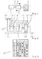
- Fig. 1 shows a highly schematic drive train scheme of a motor vehicle.
- the drive train is formed by a drive unit 1, an automatic transmission 2 and driven wheels 3 of the motor vehicle.
- the automatic transmission 2 sets a traction power supply of the drive unit 1 to the wheels 3 of the motor vehicle.
- the invention relates to a method for operating a drive train, comprising a drive unit 1 and an automatic transmission 2, wherein the automatic transmission 2 has at least five switching elements, and wherein for torque transmission or power transmission a maximum of two switching elements in a forward gear and in a reverse gear open and the rest Switching elements are closed.
- An exemplary example of such an automatic transmission show FIGS. 2 and 3 , Although the invention will be described in more detail below with reference to this example, it is not limited in its use to this example of an automatic transmission.
- Fig. 2 shows a transmission diagram 6 of a stepped automatic transmission 2, which has four gear sets 7, 8, 9 and 10 in order to implement a present at a transmission input 11 transmission input torque in a transmission output torque at a transmission output 12.
- the gear sets 7, 8, 9 and 10 of the automatic transmission 2 are according to Fig. 2 designed as planetary gear sets.
- the automatic transmission in addition to the four gear sets 7 to 10 continue to have five switching elements 13, 14, 15, 16 and 17, the switching element 13 is also used as switching element A, the switching element 14 as a switching element B, the switching element 15 as a switching element C, the Switching element 16 also referred to as switching element D and the switching element 17 as a switching element E.
- the switching element A and switching element B are each brakes
- in the switching elements C, D and E are each clutches.
- successive upshifts or successive downshifts are performed interleaved, namely such that at a first upshift or downshift at least one required for a subsequent second upshift or downshift switching element is prepared during the current first upshift or downshift, namely such that when a synchronization point of the current first upshift or downshift is reached, the immediate execution of the subsequent second upshift or downshift is possible.
- switching elements A B C D e downshift 8-6 (6-5) a vz z x va 7-5 (5-4) a z va x vz 5-3 (3-2) vz x va a z 4-2 (2-1) z x vz a va 8-4 (4-3) a z vz va x 8-2 (2-1) x z vz a va 6-3 (3-2) vz z va a x 7-5 (5-3) a z x va vz 6-4 (4-2) vz z a va x upshift 1-3 (3-4) a x va vz z 2-4 (4-5) a x vz z va 4-6 (6-7) vz a z x va 5-7 (7-8) z a va x vz
- switching elements which are closed during a first upshift or downshift to be executed and thus switched on are marked with "z".
- switching elements that are opened and thus switched off during a first upshift or downshift are marked “a” in the above table.
- Switching elements that are prepared during a first upshift or downshift for a subsequent second upshift or downshift for closing and thus switching on or for opening and thus switching off are identified in the above table with "vz” or "va”. With "x" marked switching elements are and remain closed during an upshift or downshift.
- multiple gearshifts are executed both as first upshifts and as first downshifts.
- a multiple circuit as a first upshift or downshift
- a single circuit not part of the invention or a multiple circuit is prepared as a second subsequent upshift or downshift.
- First multiple downshifts are in accordance with the above table double downshifts or triple downshifts or quadruple downshifts or even six-fold downshifts.
- subsequent second multiple downshifts are double downshifts,
- First multiple upshifts are always double upshifts.
- a single upshift is prepared during a first multiple upshift performed as a double upshift.
- a first shift element is opened and thus turned off, and a second shift element is closed and thereby engaged.
- a third switching element for opening and thus switching off and a fourth switching element for closing and thus switching.
- a fifth shift element is closed or kept approximately closed.
- the first downshift is performed as a multiple circuit, namely as a double circuit.
- the second downshift is prepared as a single circuit during execution of the first downshift. It can be z.
- the above table may be nested downs 7-5 (5-4) or 4-2 (2-1).
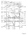
- Fig. 4 time profiles of different signals are plotted, with a signal curve 19 visualizing a driver-request-dependent desired gear, a signal curve 20 visualizing a target gear determined on the basis of the target gear, wherein a signal curve 21 visualizes an actual gear, wherein a signal curve 22 a torque of the drive unit 1 of the drive train and a waveform 23, a speed of the drive unit 1 visualized.
- the waveforms 24, 25, 26, 27 and 28 visualize the control or the temporal behavior of five involved in the interleaved execution of two successive downshifts switching elements, the waveform 24, the temporal behavior of a first to be opened during the first downshift and thus disconnected first Visualized the switching element, the waveform 25 visualizes the temporal behavior of the first downshift to be closed and thus zuzupillarden second switching element, the waveform 26 visualizes the temporal behavior of the third switch element to be prepared during the first downshift for the subsequent second downshift to open and thus shutdown and wherein the waveform 27, the temporal behavior of the fourth Druckelemen to be prepared during the execution of the first downshift for a subsequent second downshift for closing and thus switching Visualized, the waveform 28 visualizes the temporal behavior of a fifth switching element, which during the execution of the the first upshift or downshift and during the execution of the second upshift or downshift is kept closed or approximately closed.
- the fifth switching element (see signal curve 28) is kept closed.
- the third switch element (see waveform 26) is prepared for opening or shutting down.
- time F a transition phase of the prepared for the subsequent second downshift third and thus the prepared switching off switching element is started, wherein at the time S, which corresponds to a synchronization point of the first downshift, a change from the first downshift to the subsequent second downshift takes place.
- the switching elements prepared during the first downshift are the active switching elements of the subsequent second downshift.
- the fourth switching element prepared for closing and thus connecting during the first switch-back is the closing switching element of the second reset circuit.
- the switching off in the first downshift and thus opening first switching element is switched off from the time H reached the third switching element that was prepared for opening or switching off, the Abschaltdruckluster.
- the fifth switching element (see waveform 28) is kept closed or approximately closed during the execution of the first downshift and during the execution of the second downshift.
- switching elements are prepared for any subsequent third downshift, which in turn is a single downshift (see waveforms 29 and 30).
- the fourth shift element (see waveform 27) to be closed during the second downshift is prepared for closing at a time C by tailing, which is timed or event controlled Applicable first time period T 1 before reaching the synchronization point of the current first downshift at time S is.
- the time-controlled or event-controlled applicable first time period T 1 can, for. B. over a time reservation or a differential speed relative to the synchronization point S of the first downshift can be realized.
- the instant C which results from the synchronization point S of the current first downshift and from the administrable first time span T 1 , lies ahead of the end (instant B) of the fast filling phase of the second switching element to be closed during the first downshift, then the Preparation of the fourth switching element delayed until the Schnellbehellungsphase of closing during the first downshifting second switching element is completed.
- the fourth switching element (see signal curve 27) prepared for the second downshift during the execution of the first downshift for closing is transferred from the preparation phase into the switching phase at time G.
- This time G is a time-controlled or event-controlled applicable second time T 2 before the synchronization point S of the first downshift. Then, if so Fig. 4 shows that this time G, which results from the synchronization point S of the first downshift and the applicable second time period T 2 , temporally after the end of the Schnellbe hydrolungsphase (time E) to be closed during the second downshift fourth switching element, during the second Downshift to be closed fourth switching element transferred directly from the preparation phase into the switching phase
- the transition of the fourth switching element is delayed from the preparation phase in the switching phase until the Schnellbehellungsphase the fourth switching element is completed.
- the third switching element prepared for opening and thus switching off during the execution of the first downshift for the subsequent second downshift is transferred from the preparation phase to the switching phase at time F, this time F being a time span T controlled by a time control or event control 3 before reaching the synchronization point S of the first downshift is.
- a prepared sequential circuit is only executed if this corresponds to a driver's request. So can Fig. 4 be taken that at time F according to the driver's request representing waveform 19 for the desired gear, a further downshift (x-3) is desired, so that the second downshift then in the example of Fig. 4 is actually executed.
- corresponding switching elements are prepared during the second downshift for a third subsequent downshift according to the signal curves 29 and 30, wherein Fig. 4 for the third downshift to be prepared during the second downshift, the correspondingly applicable first time period T ' 1 , second time period T' 2 and third time period T ' 3 are related to a synchronization point S' of the second downshift.
- the execution of the second downshift prepared third downshift is a single downshift.
- Fig. 4 It can be seen that at a defined by the synchronous point S 'of the second downshift and the applicable third time T' 3 time based on the driver's request representing waveform 19 for the desired gear no further downshift is desired, so that during the second Downshift prepared third downshift not executed, but rather is canceled.
- the actual gear is set to recognize a new value with recognition of the synchronization points S and S 'of a running circuit, while the target gear according to the waveform 20 depends on the target gear according to the waveform 19th changes to the next gear or remains unchanged.
- a third aspect of the present invention for the in Fig. 4
- torque of the power plant is increased and / or decreased relative to a driver-derived torque for the power plant so as to support the interleaved execution of the successive downshifts.
- in Fig. 4 waveform shown in solid lines 22 a derived from a driver request torque for the drive unit.
- the moment of the drive unit is increased both during the execution of the first downshift and during the execution of the second downshift against the torque derived from the driver for the drive unit.
- the torque for the drive unit to the end of the second downshift reduced compared to the driver's request derived torque for the drive unit. Both variants will be discussed in greater detail below.
- dot-dash line drawn elevation of the torque of the drive unit relative to the driver-derived torque for the drive unit takes place when the drive train is operated either in overrun mode or in part load train operation.
- an increase in torque of the drive unit relative to the torque derived from the driver is performed, is checked during each executed downshift, if a prepared sequential return corresponds to the driver's request. This takes place at a point in time which depends on the one hand on the synchronization point S and on the other hand on the applicable third time span T 3 , that is to say in the exemplary embodiment of FIG Fig. 4 at time F.
- a transition between the torque increase of the first downshift and the torque increase of the second downshift is performed, in the embodiment shown, the torque increase of the second downshift is greater than the torque increase of the first downshift. In contrast, it is also possible that the torque increase of the second downshift is smaller than the torque increase of the first downshift. Likewise, both torque increases can be the same size. Between the two torque increases preferably a ramp-like transition is performed.
- the prepared Sequence circuit aborted and terminated the circuit to increase the torque for the drive unit. This is in Fig. 4 for the prepared during the second downshift third downshift.
- two successive downshifts can be executed as interleaved circuits by driving five switching elements, according to FIG Fig. 4 to execute the first downshift as a multiple circuit a first switching element (waveform 24) opened and thus turned off and a second switching element (waveform 25) is closed and thus switched on.
- the third switching element (signal curve 26) is prepared for opening and thus switching off for the subsequent second downshift and the fourth switching element (signal curve 27) is prepared for closing and thus switching on.
- the fifth switching element (waveform 28) is kept closed during the execution of the first downshift and during the execution of the second downshift.
- the inventive method is applicable to all automatic transmissions, which have at least five switching elements, and wherein for torque transmission or power transmission a maximum of two of these at least five switching elements open and the other switching elements are closed.
Landscapes
- Engineering & Computer Science (AREA)
- General Engineering & Computer Science (AREA)
- Mechanical Engineering (AREA)
- Control Of Transmission Device (AREA)
- Control Of Multiple Motors (AREA)
- Valve Device For Special Equipments (AREA)
Abstract
Description
Die Erfindung betrifft ein Verfahren zum Betreiben eines zumindest ein Automatgetriebe und ein Antriebsaggregat umfassenden Antriebsstrangs eines Kraftfahrzeugs nach dem Oberbegriff des Anspruchs 1.The invention relates to a method for operating a drive train, comprising at least one automatic transmission and a drive unit, of a motor vehicle according to the preamble of
Die Hauptkomponenten eines Antriebsstrangs eines Kraftfahrzeugs sind ein Antriebsaggregat und ein Getriebe. Ein Getriebe wandelt Drehmomente und Drehzahlen und setzt so das Zugkraftangebot des Antriebsaggregats um. Die hier vorliegende Erfindung betrifft ein Verfahren zum Betreiben eines Antriebsstrangs, der zumindest ein Antriebsaggregat und ein Automatgetriebe umfasst. Im Sinne der hier vorliegenden Erfindung sollen unter dem Begriff Automatgetriebe alle Getriebe mit einem automatischen Gangwechsel verstanden werden, die auch als Stufenautomatgetriebe bezeichnet werden.The main components of a drive train of a motor vehicle are a drive unit and a transmission. A gearbox converts torques and speeds and thus converts the tractive power of the drive unit. The present invention relates to a method for operating a drive train, which comprises at least one drive unit and an automatic transmission. For the purposes of the present invention, the term automatic transmission is understood to mean all transmissions with an automatic gear change, which are also referred to as a stepped automatic transmission.
Aus der
Dabei werden nach der
Das aus der
Hinsichtlich weiteren druckschriftlichen Standes der Technik wird verwiesen auf
Hiervon ausgehend liegt der vorliegenden Erfindung das Problem zu Grunde, ein neuartiges Verfahren zum Betreiben eines zumindest ein Automatgetriebe und ein Antriebsaggregat umfassenden Antriebsstrangs zu schaffen.On this basis, the present invention is based on the problem to provide a novel method for operating a drive train comprising at least one automatic transmission and a drive unit.
Dieses Problem wird durch ein Verfahren gemäß Anspruch 1 gelöst. Erfindungsgemäß sind bei einem Automatgetriebe mit mindestens fünf Schaltelementen, von welchen zur Moment- bzw. Kraftübertragung in einem Vorwärtsgang bzw. in einem Rückwärtsgang jeweils maximal zwei Schaltelemente geöffnet und die übrigen Schaltelemente geschlossen sind, zwei aufeinanderfolgende Hochschaltungen bzw. zwei aufeinanderfolgende Rückschaltungen durch Ansteuerung von mindestens fünf Schaltelementen derart ausführbar, dass:
- a) eine erste Hochschaltung bzw. Rückschaltung als Mehrfachschaltung ausgeführt wird, wobei während der laufenden ersten Hochschattung bzw. Rückschaltung als nachfolgende zweite Hochschaltung bzw. Rückschaltung eine Mehrfachschaltung vorbereitet wird;
- b) bei der Ausführung der ersten Hochschaltung bzw. Rückschaltung als Mehrfachschaltung ein erstes Schaltelement des Automatgetriebes geöffnet und damit abgeschaltet sowie ein zweites Schaltelement des Automatgetriebes geschlossen und damit zugeschaltet wird;
- c) während der Ausführung der ersten Hochschaltung bzw. Rückschaltung als Mehrfachschaltung für die nachfolgende zweite Hochschaltung bzw. Rückschaltung ein drittes Schaltelement des Automatgetriebes zum Öffnen und damit Abschalten sowie ein viertes Schaltelement des Automatgetriebes zum Schließen und damit Zuschalten vorbereitet wird;
- d) während der Ausführung der ersten Hochschaltung bzw. Rückschaltung und während der Ausführung der zweiten Hochschaltung bzw. Rückschaltung mindestens ein fünftes Schaltelement geschlossen bzw. annähernd geschlossen gehalten wird.
- a) a first upshift or downshift is performed as a multiple circuit, wherein during the current first Hochschattung or downshift as a subsequent second upshift or downshift a multiple circuit is prepared;
- b) in the execution of the first upshift or downshift as a multiple circuit a first switching element of the automatic transmission is opened and thus switched off and a second switching element of the automatic transmission is closed and thus switched on;
- c) during the execution of the first upshift or downshift as a multiple circuit for the subsequent second upshift or downshift a third shift element of the automatic transmission for opening and thus switching off and a fourth shift element of the automatic transmission is prepared for closing and thus switching;
- d) during the execution of the first upshift or downshift and during the execution of the second upshift or downshift at least a fifth switching element is kept closed or approximately closed.
Nach einer vorteilhaften Weiterbildung der Erfindung wird während der Ausführung einer ersten Hochschaltung bzw. Rückschaltung für eine nachfolgende zweite Hochschaltung bzw. Rückschaltung ein während der zweiten Hochschaltung bzw. Rückschaltung schließendes Schaltelement zu einem Zeitpunkt zum Schließen vorbereitet, der um eine zeitgesteuert oder ereigneisgesteuert applizierbare erste Zeitspanne vor dem Erreichen des Synchronpunkts der laufenden ersten Hochschaltung bzw. Rückschaltung liegt.According to an advantageous embodiment of the invention, during the execution of a first upshift or downshift for a subsequent second upshift or downshift a closing during the second upshift or downshifting switching element is prepared for closing at a time, which can be applied by a time-controlled or event-controlled first time period before the Reaching the synchronization point of the current first upshift or downshift is.
Nach einer weiteren vorteilhaften Weiterbildung der Ereindung wird während der Ausführung einer ersten Hochschaltung bzw. Rückschaltung und/oder während der Ausführung einer zweiten, nachfolgenden Hochschaltung bzw. Rückschaltung ein Moment des Antriebsaggregats gegenüber einem von einem Fahrerwunsch abgeleiteten Moment für das Antriebsaggregat erhöht und/oder verringert, um die verschachtelte Ausführung aufeinanderfolgender Hochschaltungen bzw. Rückschaltungen zu unterstützen.According to a further advantageous embodiment of the invention, during the execution of a first upshift or downshift and / or during the execution of a second, subsequent upshift or downshift, a torque of the drive unit is increased and / or reduced in relation to a torque derived from a driver request for the drive unit in order to support the interleaved execution of successive upshifts or downshifts.
Bevorzugte Weiterbildungen der Erfindung ergeben sich aus den Unteransprüchen und der nachfolgenden Beschreibung. Ausführungsbeispiele der Erfindung werden, ohne hierauf beschränkt zu sein, an Hand der Zeichnung näher erläutert. Dabei zeigt:
- Fig. 1
- ein Antriebsstrangschema eines Kraftfahrzeugs;
- Fig. 2
- ein Getriebeschema eines Automatgetriebes des Antriebsstrangs mit fünf Schaltelementen;
- Fig. 3
- eine Schaltelementmatrix für die Schaltelemente des Getriebeschemas der
Fig. 2 zur Verdeutlichung welche Schaltelemente in welchem Gang geschlossen sind und - Fig. 4
- ein Diagramm zur Verdeutlichung des erfindungsgemäßen Verfahrens zum Betreiben eines Antriebsstrangs eines Kraftfahrzeugs, der ein Automatgetriebe gemäß
Fig. 2 und 3 umfasst.
- Fig. 1
- a powertrain diagram of a motor vehicle;
- Fig. 2
- a transmission diagram of an automatic transmission of the drive train with five switching elements;
- Fig. 3
- a switching element matrix for the switching elements of the transmission scheme of
Fig. 2 to clarify which switching elements are closed in which gear and - Fig. 4
- a diagram to illustrate the inventive method for operating a drive train of a motor vehicle, the automatic transmission according to
FIGS. 2 and 3 includes.
Dann, wenn der Antriebsstrang gemäß
Die Erfindung betrifft ein Verfahren zum Betreiben eines Antriebsstrangs, der ein Antriebsaggregat 1 und ein Automatgetriebe 2 umfasst, wobei das Automatgetriebe 2 mindestens fünf Schaltelemente aufweist, und wobei zur Momentübertragung bzw. Kraftübertragung maximal zwei Schaltelemente in einem Vorwärtsgang sowie in einem Rückwärtsgang geöffnet und die übrigen Schaltelemente geschlossen sind. Ein exemplarisches Beispiel für ein solches Automatgetriebe zeigen
Die Getrieberadsätze 7, 8, 9 und 10 des Automatgetriebes 2 sind dabei gemäß
Für das in
Zur Verbesserung der Schaltgeschwindigkeit werden aufeinanderfolgende Hochschaltungen bzw. aufeinanderfolgende Rückschaltungen verschachtelt ausgeführt, nämlich derart, dass bei einer ersten Hochschaltung bzw. Rückschaltung mindestens ein für eine nachfolgende zweite Hochschaltung bzw. Rückschaltung benötigtes Schaltelement während der laufenden ersten Hochschaltung bzw. Rückschaltung vorbereitet wird, und zwar derart, dass bei Erreichen eines Synchronpunkts der laufenden ersten Hochschaltung bzw. Rückschaltung die sofortige Durchführung der nachfolgenden zweiten Hochschaltung bzw. Rückschaltung möglich ist.To improve the switching speed, successive upshifts or successive downshifts are performed interleaved, namely such that at a first upshift or downshift at least one required for a subsequent second upshift or downshift switching element is prepared during the current first upshift or downshift, namely such that when a synchronization point of the current first upshift or downshift is reached, the immediate execution of the subsequent second upshift or downshift is possible.
In der nachfolgenden Tabelle sind für das in
In der Tabelle sind Schaltelemente, die während einer auszuführenden ersten Hochschaltung bzw. Rückschaltung geschlossen und damit zugeschaltet werden, mit "z" gekennzeichnet. Schaltelemente, die hingegen während einer ersten Hochschaltung bzw. Rückschaltung geöffnet und damit abgeschaltet werden, sind in der obigen Tabelle mit "a" gekennzeichnet. Schaltelemente, die während einer ersten Hochschaltung bzw. Rückschaltung für eine nachfolgende zweite Hochschaltung bzw. Rückschaltung zum Schließen und damit Zuschalten oder zum Öffnen und damit Abschalten vorbereitet werden, sind in der obigen Tabelle mit "vz" oder "va" gekennzeichnet. Mit "x" gekennzeichnete Schaltelemente sind und bleiben während einer Hochschaltung bzw. Rückschaltung geschlossen.In the table, switching elements which are closed during a first upshift or downshift to be executed and thus switched on are marked with "z". On the other hand, switching elements that are opened and thus switched off during a first upshift or downshift are marked "a" in the above table. Switching elements that are prepared during a first upshift or downshift for a subsequent second upshift or downshift for closing and thus switching on or for opening and thus switching off are identified in the above table with "vz" or "va". With "x" marked switching elements are and remain closed during an upshift or downshift.
Bei Verwendung der obigen Tabelle für das Automatgetriebe der
Erste Mehrfachrückschaltungen sind gemäß der obigen Tabelle Doppelrückschaltungen oder Dreifachrückschaltungen oder Vierfachrückschaltungen oder gar Sechsfachrückschaltungen. Gegebenfalls nachfolgende zweite Mehrfachrückschaltungen sind Doppelrückschaltungen,First multiple downshifts are in accordance with the above table double downshifts or triple downshifts or quadruple downshifts or even six-fold downshifts. Optionally subsequent second multiple downshifts are double downshifts,
Erste Mehrfachhochschaltungen sind stets Doppelhochschaltungen. Als zweite, nachfolgende Hochschaltung wird während einer als Doppelhochschaltungen ausgeführten ersten Mehrfachhochschaltung eine Einfachhochschaltung vorbereitet.First multiple upshifts are always double upshifts. As a second, subsequent upshift, a single upshift is prepared during a first multiple upshift performed as a double upshift.
Nach einem ersten Aspekt der hier vorliegenden Erfindung wird bei Ausführung einer ersten Hochschaltung bzw. Rückschaltung als Mehrfachschaltung ein erstes Schaltelement geöffnet und damit abgeschaltet sowie ein zweites Schaltelement geschlossen und damit zugeschaltet. Während der Ausführung der ersten Hochschaltung bzw. Rückschaltung als Mehrfachschaltung wird dann für die nachfolgende zweite Hochschaltung bzw. Rückschaltung, die als Mehrfachschaltung vorbereitet und gegebenenfalls ausgeführt wird, ein drittes Schaltelement zum Öffnen und damit Abschalten sowie ein viertes Schaltelement zum Schließen und damit Zuschalten vorbereitet. Während der Ausführung der ersten Hochschaltung bzw. Rückschaltung und während der Ausführung der zweiten Hochschaltung bzw. Rückschaltung wird mindestens ein fünftes Schaltelement geschlossen bzw. annähernd geschlossen gehalten wird.According to a first aspect of the present invention, when a first upshift or downshift is performed as a multiple circuit, a first shift element is opened and thus turned off, and a second shift element is closed and thereby engaged. During the execution of the first upshift or downshift as a multiple circuit is then prepared for the subsequent second upshift or downshift, which is prepared as a multiple circuit and optionally executed, a third switching element for opening and thus switching off and a fourth switching element for closing and thus switching. During the execution of the first upshift or downshift and during the execution of the second upshift or downshift, at least a fifth shift element is closed or kept approximately closed.
Dieser erste Aspekt einem nicht zur Erfindung gehörenden wird nachfolgend unter Bezugnahme auf
In
Die Signalverläufe 24, 25, 26, 27 und 28 visualisieren die Ansteuerung bzw. das zeitliche Verhalten von fünf bei der verschachtelten Ausführung von zwei aufeinanderfolgenden Rückschaltungen beteiligten Schaltelementen, wobei der Signalverlauf 24 das zeitliche Verhalten eines bei der ersten Rückschaltung zu öffnenden und damit abzuschaltenden ersten Schaltelements visualisiert, wobei der Signalverlauf 25 das zeitliche Verhalten des bei der ersten Rückschaltung zu schließenden und damit zuzuschaltenden zweiten Schaltelements visualisiert, wobei der Signalverlauf 26 das zeitliche Verhalten des während der ersten Rückschaltung für die nachfolgende zweite Rückschaltung zum Öffnen und damit Abschalten vorzubereitenden dritten Schaltelements visualisiert, und wobei der Signalverlauf 27 das zeitliche Verhalten des während der Ausführung der ersten Rückschaltung für eine nachfolgende zweite Rückschaltung zum Schließen und damit Zuschalten vorzubereitenden vierten Schaltelements visualisiert, Der Signalverlauf 28 visualisiert das zeitliche Verhalten eines fünften Schaltelements, welches während der Ausführung der ersten Hochschaltung bzw, Rückschaltung und während der Ausführung der zweiten Hochschaltung bzw. Rückschaltung geschlossen bzw. annähernd geschlossen gehalten wird.The
Im Zeitpunkt A liegt eine Veränderung des Soll-Gangs (siehe Signalverlauf 19) und abgeleitet hiervon eine Veränderung des Ziel-Gangs (siehe Signal-verlauf 20) im Sinne einer gewünschten Mehrfachrückschaltung um zwei Gänge (x-2) vor, wobei dies die verschachtelte Ausführung bzw. Vorbereitung von aufeinanderfolgenden Rückschaltungen auslöst, nämlich derart, dass zum Zeitpunkt A einerseits das bei Ausführung der ersten Rückschaltung zu öffnende und damit abzuschaltende erste Schaltelement (siehe Signalverlauf 24) mit der Schaltphase beginnt, und dass andererseits das bei der Ausführung der ersten Rückschaltung zu schließende und damit zuzuschaltende zweite Schaltelement (siehe Signalverlauf 25) einer Schnellbefüllung unterzogen wird, wobei die Schnellbefüllung zwischen den Zeitpunkten A und B erfolgt.At time A, there is a change in the target gear (see waveform 19) and derived therefrom a change in the target gear (see signal curve 20) in the sense of a desired multiple downshift by two gears (x-2), this being the interleaved Execution or preparation of successive downshifts triggers, namely such that at time A, on the one hand, when opening the first downshift to be opened and thus disconnected first switching element (see waveform 24) begins with the switching phase, and that on the other hand in the execution of the first downshift to be closed and thus zuzuschaltende second switching element (see waveform 25) is subjected to a quick filling, wherein the fast filling between the times A and B takes place.
Das während der Ausführung der ersten Rückschaltung, die eine Mehrfachschaltung ist, für die nachfolgende zweite Rückschaltung, die eine Einfachschaltung ist, vorzubereitende dritte Schaltelement (siehe Signalverlauf 26) sowie das vierte Schaltelement (siehe Signalverlauf 27) werden zum Zeitpunkt A auf einen definierten Zustand gesetzt. Das fünfte Schaltelement (siehe Signalverlauf 28) wird geschlossen gehalten.The third switching element to be prepared during the execution of the first downshift, which is a multiple circuit, for the subsequent second downshift, which is a single circuit (see waveform 26), and the fourth switching element (see waveform 27) are set to a defined state at time A , The fifth switching element (see signal curve 28) is kept closed.
Nach Ablauf der Schnellbefüllung des in der ersten Rückschaltung zu schließenden und damit zuzuschaltenden zweiten Schaltelements (siehe Signalverlauf 25) geht das zweite Schaltelement von der Schnellbefüllungsphase in eine Füllausgleichsphase über, wobei sich die Füllausgleichsphase zwischen den Zeitpunkten B und D erstreckt. Die Schnellbefüllungsphase zwischen den Zeitpunkten A und B und die Füllausgleichsphase zwischen den Zeitpunkten B und D definieren zusammen die Befüllungsphase des während der ersten Rückschaltung zu schließenden zweiten Schaltelements. Im Zeitpunkt D wird das während der ersten Rückschaltung zu schließende und damit zuzuschaltende zweite Schaltelement (siehe Signalverlauf 25) von der Befüllungsphase in die Schaltphase überführt.After expiration of the fast filling of the first downshift to be closed and thus zuzuschaltenden second switching element (see waveform 25) is the second switching element of the fast filling phase in a Füllausgleichsphase, wherein the Füllausgleichsphase extends between the times B and D. The fast filling phase between times A and B and the filling equalization phase between times B and D together define the filling phase of the second switching element to be closed during the first downshift. At time D will the second switching element to be closed during the first switch-back and therefore to be connected (see signal curve 25) is transferred from the filling phase into the switching phase.
Während der Ausführung der ersten Rückschaltung als Mehrfachschaltung, während der das erste Schaltelement gemäß dem Signalverlauf 24 geöffnet und damit abgeschaltet und das zweite Schaltelement gemäß dem Signal-verlauf 25 geschlossen und damit zugeschaltet wird, erfolgt eine Vorbereitung von zwei Schaltelementen für eine eventuell nachfolgend, im Beispiel als Einfachschaltung auszuführende zweite Rückschaltung.During the execution of the first downshift as a multiple circuit, during which the first switching element according to the
So erfolgt zum Zeitpunkt C die Vorbereitung des in einer eventuell nachfolgenden zweiten Rückschaltung zu schließenden und damit zuzuschaltenden vierten Schaltelements (siehe Signalverlauf 27) mit einer Schnellbefüllung, die sich zwischen den Zeitpunkten C und E erstreckt,Thus, at time C, the preparation of the fourth switching element to be closed in a possible subsequent second downshift and thus to be connected (see signal curve 27) takes place with a rapid filling which extends between times C and E,
Mit Abschluss der Schnellbefüllung des vierten Schaltelements zum Zeitpunkt E wechselt dasselbe in eine Füllausgleichsphase, die gemäß
Ebenso wird während der Ausführung der ersten Rückschaltung für eine nachfolgende zweite Rückschaltung das dritte Schaltelement (siehe Signalverlauf 26) zum Öffnen bzw. Abschalten vorbereitet. Zum Zeitpunkt F wird eine Übergangsphase des für die nachfolgende zweite Rückschaltung vorbereiteten dritten und damit des vorbereiteten abschaltenden Schaltelements gestartet, wobei im Zeitpunkt S, der einem Synchronpunkt der ersten Rückschaltung entspricht, ein Wechsel von der ersten Rückschaltung auf die nachfolgende zweite Rückschaltung erfolgt.Likewise, during the execution of the first downshift for a subsequent second downshift, the third switch element (see waveform 26) is prepared for opening or shutting down. At time F, a transition phase of the prepared for the subsequent second downshift third and thus the prepared switching off switching element is started, wherein at the time S, which corresponds to a synchronization point of the first downshift, a change from the first downshift to the subsequent second downshift takes place.
Mit Erreichen des Zeitpunkts S sind die während der ersten Rückschaltung vorbereiteten Schaltelemente die aktiven Schaltelemente der nachfolgenden zweiten Rückschaltung. So wird zum Zeitpunkt G das während der ersten Rückschaltung zum Schließen und damit Zuschalten vorbereitete vierte Schaltelement zum schließenden Schaltelement der zweiten Rückschaltung. Das in der ersten Rückschaltung abschaltende und damit öffnende erste Schaltelement wird weggeschaltet Ab dem Zeitpunkt H erreicht das dritte Schaltelement das zum Öffnen bzw. Abschalten vorbereitet wurde, das Abschaltdruckniveau.Upon reaching the time point S, the switching elements prepared during the first downshift are the active switching elements of the subsequent second downshift. Thus, at time G, the fourth switching element prepared for closing and thus connecting during the first switch-back is the closing switching element of the second reset circuit. The switching off in the first downshift and thus opening first switching element is switched off from the time H reached the third switching element that was prepared for opening or switching off, the Abschaltdruckniveau.
Das fünfte Schaltelement (siehe Signalverlauf 28) wird während der Ausführung der ersten Rückschaltung und während der Ausführung der zweiten Rückschaltung geschlossen bzw. annähernd geschlossen gehalten.The fifth switching element (see waveform 28) is kept closed or approximately closed during the execution of the first downshift and during the execution of the second downshift.
Während der nachfolgenden zweiten Rückschaltung werden Schaltelemente für eine eventuell nachfolgende dritte Rückschaltung, die wiederum eine Einfachrückschaltung ist, vorbereitet (siehe Signalverläufe 29 und 30).During the subsequent second downshift, switching elements are prepared for any subsequent third downshift, which in turn is a single downshift (see
Nach einem zweiten Aspekt der hier vorliegenden Erfindung wird während der Ausführung der ersten Rückschaltung für die nachfolgende zweite Rückschaltung das während der zweiten Rückschaltung zu schließende vierte Schaltelement (siehe Signalverlauf 27) zu einem Zeitpunkt C durch Schneilbefüllung zum Schließen vorbereitet, der um eine zeitgesteuert oder ereignisgesteuert applizierbare erste Zeitspanne T1 vor dem Erreichen des Synchronpunkts der laufenden ersten Rückschaltung im Zeitpunkt S liegt. Die zeitgesteuert oder ereignisgesteuert applizierbare erste Zeitspanne T1 kann z. B. über einen Zeitvorbehalt oder eine Differenzdrehzahl relativ zum Synchronpunkt S der ersten Rückschaltung realisiert werden.According to a second aspect of the present invention, during the execution of the first downshift for the subsequent second downshift, the fourth shift element (see waveform 27) to be closed during the second downshift is prepared for closing at a time C by tailing, which is timed or event controlled Applicable first time period T 1 before reaching the synchronization point of the current first downshift at time S is. The time-controlled or event-controlled applicable first time period T 1 can, for. B. over a time reservation or a differential speed relative to the synchronization point S of the first downshift can be realized.
Dann, wenn der Zeitpunkt C, der sich aus dem Synchronpunkt S und der applizierbaren ersten Zeitspanne T1 ergibt, wie in
Sollte hingegen der Zeitpunkt C, der sich aus dem Synchronpunkt S der laufenden ersten Rückschaltung und aus der applizierbaren ersten Zeitspanne T1 ergibt, zeitlich vor dem Ende (Zeitpunkt B) der Schnellbefüllungsphase des während der ersten Rückschaltung zu schließenden zweiten Schaltelements liegen, so wird die Vorbereitung des vierten Schaltelements so lange verzögert, bis die Schnellbefüllungsphase des während der ersten Rückschaltung zu schließenden zweiten Schaltelements abgeschlossen ist.If, on the other hand, the instant C, which results from the synchronization point S of the current first downshift and from the administrable first time span T 1 , lies ahead of the end (instant B) of the fast filling phase of the second switching element to be closed during the first downshift, then the Preparation of the fourth switching element delayed until the Schnellbefüllungsphase of closing during the first downshifting second switching element is completed.
Wie bereits erwähnt, wird das für die zweite Rückschaltung während der Ausführung der ersten Rückschaltung zum Schließen vorbereitete vierte Schaltelement (siehe Signalverlauf 27) zum Zeitpunkt G von der Vorbereitungsphase in die Schaltphase überführt.As already mentioned, the fourth switching element (see signal curve 27) prepared for the second downshift during the execution of the first downshift for closing is transferred from the preparation phase into the switching phase at time G.
Dieser Zeitpunkt G liegt um eine zeitgesteuert oder ereignisgesteuert applizierbare zweite Zeitspane T2 vor dem Synchronpunkt S der ersten Rückschaltung. Dann, wenn wie
Sollte hingegen der Zeitpunkt G, der sich aus dem Synchronpunkt S der laufenden ersten Rückschaltung und der applizierbaren zweiten Zeitspanne T2 ergibt, zeitlich vor dem Ende der Schnellbefüllungsphase (Zeitpunkt E) des während der zweiten Rückschaltung zu schließenden vierten Schaltelements liegen, so wird der Übergang des vierten Schaltelements von der Vorbereitungsphase in die Schaltphase so lange verzögert, bis die Schnellbefüllungsphase des vierten Schaltelements abgeschlossen ist.If, on the other hand, the point in time G, which results from the synchronization point S of the current first downshift and the administrable second time period T 2 , should be timed before the end of the rapid filling phase (time E) of during the second downshift lie to be closed fourth switching element, the transition of the fourth switching element is delayed from the preparation phase in the switching phase until the Schnellbefüllungsphase the fourth switching element is completed.
Wie oben bereits ausgeführt, wird das während der Ausführung der ersten Rückschaltung für die nachfolgende zweite Rückschaltung zum Öffnen und damit Abschalten vorbereitete dritte Schaltelement zum Zeitpunkt F von der Vorbereitungsphase in die Schaltphase überführt, wobei dieser Zeitpunkt F um eine zeitgesteuert oder ereignisgesteuert applizierbare dritte Zeitspanne T3 vor dem Erreichen des Synchronpunkts S der ersten Rückschaltung liegt.As already stated above, the third switching element prepared for opening and thus switching off during the execution of the first downshift for the subsequent second downshift is transferred from the preparation phase to the switching phase at time F, this time F being a time span T controlled by a time control or event control 3 before reaching the synchronization point S of the first downshift is.
Zum Zeitpunkt F wird im gezeigten Ausführungsbeispiel entschieden, ob die während der ersten Rückschaltung vorbereitete zweite Rückschaltung tatsächlich ausgeführt wird.At time F, it is decided in the illustrated embodiment whether the second downshift prepared during the first downshift is actually executed.
So wird eine vorbereitete Folgeschaltung nämlich nur dann ausgeführt, wenn dies einem Fahrerwunsch entspricht. So kann
Wie bereits ausgeführt, werden auch während der zweiten Rückschaltung für eine dritte nachfolgende Rückschaltung gemäß den Signalverläufen 29 und 30 entsprechende Schaltelemente vorbereitet, wobei in
Wie
Nach einem dritten Aspekt der hier vorliegenden Erfindung wird für das in
Die in
Dann, wenn zu diesem Zeitpunkt auf Basis des Fahrerwunsches eine Folgerückschaltung gewünscht ist, wird ein Übergang zwischen der Drehmomenterhöhung der ersten Rückschaltung und der Drehmomenterhöhung der zweiten Rückschaltung durchgeführt, wobei im gezeigten Ausführungsbeispiel die Drehmomenterhöhung der zweiten Rückschaltung größer ist als die Drehmomenterhöhung der ersten Rückschaltung. Im Unterschied hierzu ist es auch möglich, dass die Drehmomenterhöhung der zweiten Rückschaltung kleiner ist als die Drehmomenterhöhung der ersten Rückschaltung. Ebenso können beide Drehmomenterhöhungen gleich groß sein. Zwischen den beiden Drehmomenterhöhungen wird vorzugsweise ein rampenartiger Übergang durchgeführt.Then, if at this time on the basis of the driver's request a follow-up switching is desired, a transition between the torque increase of the first downshift and the torque increase of the second downshift is performed, in the embodiment shown, the torque increase of the second downshift is greater than the torque increase of the first downshift. In contrast, it is also possible that the torque increase of the second downshift is smaller than the torque increase of the first downshift. Likewise, both torque increases can be the same size. Between the two torque increases preferably a ramp-like transition is performed.
Dann hingegen, wenn zum obigen Zeitpunkt, der durch den Synchronpunkt S und die applizierbare dritte Zeitspanne T3 definiert ist, auf Basis des Fahrerwunschs eine Folgerückschaltung nicht gewünscht ist, wird die vorbereitete Folgeschaltung abgebrochen und zur Schaltungsbeendigung die Drehmomenterhöhung für das Antriebsaggregat beendet. Dies ist in
Bei der Ausführung sowie Vorbereitung aufeinanderfolgender Rückschaltungen im Zugbetrieb des Antriebsstrangs wird während jeder ausgeführten Rückschaltung wiederum zu einem zeitgesteuert oder ereignisgesteuert applizierbaren Zeitpunkt, nämlich zu dem vom Synchronpunkt S und der applizierbaren dritten Zeitspanne T3 abhängigen Zeitpunkt, überprüft, ob eine vorbereitete Folgeschaltung einem Fahrerwunsch entspricht, Ist dies, wie in
Dann hingegen, wenn zu diesem Zeitpunkt eine Folgerückschaltung gewünscht ist, wie dies in
Im Ausführungsbeispiel der
Die in
So erfolgt bei aufeinanderfolgenden Hochschaltungen im Schubbetrieb des Antriebsstrangs für beide Hochschaltungen eine Drehmomenterhöhung, wohingegen im Zugbetrieb des in beiden Hochschaltungen eine Drehmomentreduzierung durchgeführt wird. Eine Drehmomentreduzierung zur Schaltungsbeendigung erfolgt bei aufeinanderfolgenden Hochschaltungen nicht,Thus, in successive upshifts in the overrun mode of the drive train for both upshifts an increase in torque, whereas in the train operation of a torque reduction is performed in both upshifts. A torque reduction for circuit termination does not occur in successive upshifts,
Das erfindungsgemäße Verfahren ist bei allen Automatgetrieben einsetzbar, die über mindestens fünf Schaltelemente verfügen, und wobei zur Momentübertragung bzw. Kraftübertragung maximal zwei dieser mindestens fünf Schaltelemente geöffnet und die übrigen Schaltelemente geschlossen sind.The inventive method is applicable to all automatic transmissions, which have at least five switching elements, and wherein for torque transmission or power transmission a maximum of two of these at least five switching elements open and the other switching elements are closed.
- 11
- Antriebsaggregatpower unit
- 22
- Automatgetriebeautomatic transmission
- 33
- Radwheel
- 44
- Pfeilarrow
- 55
- Pfeilarrow
- 66
- Getriebeschematransmission scheme
- 77
- Getrieberadsatztransmission gear
- 88th
- Getrieberadsatztransmission gear
- 99
- Getrieberadsatztransmission gear
- 1010
- Getrieberadsatztransmission gear
- 1111
- Getriebeeingangtransmission input
- 1212
- Getriebeausgangtransmission output
- 1313
- Schaltelement ASwitching element A
- 1414
- Schaltelement BSwitching element B
- 1515
- Schaltelement CSwitching element C
- 1616
- Schaltelement DSwitching element D
- 1717
- Schaltelement ESwitching element E
- 1818
- SchaltelementmatrixShift element matrix
- 1 91 9
- Signalverlaufwaveform
- 2020
- Signalverlaufwaveform
- 2121
- Signalverlaufwaveform
- 2222
- Signalverlaufwaveform
- 2323
- Signalverlaufwaveform
- 2424
- Signalverlaufwaveform
- 2525
- Signalverlaufwaveform
- 2626
- Signalverlaufwaveform
- 2727
- Signalverlaufwaveform
- 2828
- Signalverlaufwaveform
- 2929
- Signalverlaufwaveform
- 3030
- Signalverlaufwaveform
Claims (11)
- Method for operating a drive train of a motor vehicle, which drive train comprises at least an automated gearbox and a power engine, it being possible for upshifts which follow one another or downshifts which follow one another to be performed in an interlaced manner in such a way that, in the case of a first upshift or downshift, at least one selector element which is required for a following second upshift or downshift is prepared during the current first upshift or downshift in such a way that, when a synchronous point of the current first upshift or downshift is reached, it is possible to immediately carry out the following second upshift or downshift, characterized in that, in the case of an automated gearbox with at least five selector elements, of which, in order to transmit torque or force in a forward gear or in a reverse gear, in each case a maximum of two selector elements are open and the remaining selector elements are closed, two upshifts which follow one another or two downshifts which follow one another can be performed by actuation of at least five selector elements in such a way that:a) a first upshift or downshift is performed as a multiple shift, a multiple shift being prepared as following second upshift or downshift while the first upshift or downshift is happening;b) while the first upshift or downshift is being performed as a multiple shift, a first selector element of the automated gearbox is opened and therefore switched off and a second selector element of the automated gearbox is closed and therefore switched on;c) while the first upshift or downshift is being performed as a multiple shift for the following second upshift or downshift, a third selector element of the automated gearbox is prepared for opening and therefore switching off and a fourth selector element of the automated gearbox is prepared for closing and therefore switching on;d) while the first upshift or downshift is being performed and while the second upshift or downshift is being performed, at least one fifth selector element is kept closed or approximately closed.
- Method according to Claim 1, characterized in that, while each upshift or downshift is being performed, at least one selector element is prepared for a following upshift or downshift, the following upshift or downshift being performed, however, only when the prepared upshift or downshift corresponds to a driver's request at an instant which can be applied in a time-controlled or process-controlled manner.
- Method according to Claim 1 or 2, characterized in that, while a first upshift or downshift is being performed, a selector element which closes during a second upshift or downshift is prepared for the following second upshift or downshift at an instant for closing which lies before the synchronous point of the current first upshift or downshift is reached by a first time period which can be applied in a time-controlled or process-controlled manner.
- Method according to Claim 3, characterized in that, when this instant which results from the synchronous point of the current first upshift or downshift and the first time period which can be applied lies temporally before an end of a rapid-filling phase of a selector element which closes during the first upshift or downshift, the preparation of the selector element which closes during the second upshift or downshift is delayed until the rapid-filling phase of the selector element which closes during the first upshift or downshift is concluded, and in that otherwise the preparation of the selector element which closes during the second upshift or downshift is preferably started immediately.
- Method according to Claim 3 or 4, characterized in that the selector element which is prepared for closing for the second upshift or downshift is transferred from a preparation phase into a shifting phase at an instant which lies before the synchronous point of the current first upshift or downshift is reached by a second time period which can be applied in a time-controlled or process-controlled manner.
- Method according to Claim 5, characterized in that, when this instant which results from the synchronous point of the current first upshift or downshift and the second time period which can be applied lies temporally before an end of a rapid-filling phase of the selector element which closes during the second upshift or downshift, the transition from the preparation phase into the shifting phase is delayed until the rapid-filling phase of the selector element which closes during the second upshift or downshift is concluded, and in that otherwise the selector element which closes during the second upshift or downshift is preferably transferred from the preparation phase into the shifting phase immediately.
- Method according to one or more of Claims 3 to 6, characterized in that, while the first upshift or downshift is being performed, a selector element which opens during a following second upshift or downshift is prepared for opening for the second upshift or downshift at the beginning of the first upshift or downshift, and in that the selector element which is prepared for opening for the second upshift or downshift is transferred from a preparation phase into a shifting phase at an instant which lies before the synchronous point of the current first upshift or downshift is reached by a third time period which can be applied in a time-controlled or process-controlled manner.
- Method according to one or more of Claims 1 to 7, characterized in that, while a first upshift or downshift is being performed and/or while a second, following upshift or downshift is being performed, a torque of the power engine is increased and/or reduced with respect to a torque for the power engine which is derived from a driver's request, in order to assist the interlaced performance of upshifts or downshifts which follow one another.
- Method according to Claim 8, characterized in that, in order to perform downshifts which follow one another in the traction mode of the drive train, a check is made during each performed downshift at an instant which can be applied in a time-controlled or process-controlled manner as to whether a prepared subsequent shift operation corresponds to a driver's request, the prepared subsequent shift operation being interrupted and, in order to end the shift operation, a torque reduction of the power engine being carried out with respect to the torque for the power engine which is derived from the driver's request when a subsequent shift operation is not desired at this instant on the basis of the driving request, and the prepared subsequent shift operation being performed and the torque reduction of the power engine not being carried out when a subsequent shift operation is desired at this instant on the basis of the driving request.
- Method according to Claim 8 or 9, characterized in that, in order to perform downshifts which follow one another in the overrun mode and part-load traction mode of the drive train, a torque increase of the power engine is carried out with respect to the torque for the power engine which is derived from the driver's request during each performed downshift, a check being made during each performed downshift at an instant which can be applied in a time-controlled or process-controlled manner as to whether a prepared subsequent shift operation corresponds to a driver's request, a transition which is, in particular, ramp-like being carried out between the torque increases of the downshifts which follow one another when a subsequent shift operation is desired at this instant on the basis of the driving request, and the prepared subsequent shift operation being interrupted and the torque increase of the power engine being ended in order to end the shift operation when a subsequent shift operation is not desired at this instant on the basis of the driving request.
- Method according to one or more of Claims 8 to 10, characterized in that, in order to perform upshifts which follow one another in the traction mode of the drive train, a torque reduction of the power engine is carried out with respect to the torque which is derived from the driver's request during each performed upshift, and in that, in order to perform upshifts which follow one another in the overrun mode of the drive train, a torque increase of the power engine is carried out with respect to the torque which is derived from the driver's request during each performed upshift.
Applications Claiming Priority (1)
| Application Number | Priority Date | Filing Date | Title |
|---|---|---|---|
| DE102006026604A DE102006026604A1 (en) | 2006-06-08 | 2006-06-08 | Drive train operating method for use in motor vehicle, involves opening two of five gear shifting units of automatic transmission and closing remaining units for torque/power transmission in forward gear and/or in reverse gear |
Publications (3)
| Publication Number | Publication Date |
|---|---|
| EP1865232A2 EP1865232A2 (en) | 2007-12-12 |
| EP1865232A3 EP1865232A3 (en) | 2008-01-23 |
| EP1865232B1 true EP1865232B1 (en) | 2010-02-24 |
Family
ID=37832754
Family Applications (1)
| Application Number | Title | Priority Date | Filing Date |
|---|---|---|---|
| EP07109573A Active EP1865232B1 (en) | 2006-06-08 | 2007-06-05 | Method for operating a drive train |
Country Status (4)
| Country | Link |
|---|---|
| US (1) | US7892144B2 (en) |
| EP (1) | EP1865232B1 (en) |
| AT (1) | ATE458938T1 (en) |
| DE (2) | DE102006026604A1 (en) |
Families Citing this family (9)
| Publication number | Priority date | Publication date | Assignee | Title |
|---|---|---|---|---|
| JP4200992B2 (en) * | 2005-08-29 | 2008-12-24 | トヨタ自動車株式会社 | Shift control device for automatic transmission for vehicle |
| DE102006026605B4 (en) * | 2006-06-08 | 2022-03-31 | Zf Friedrichshafen Ag | Method of operating a power train |
| DE102006026601A1 (en) * | 2006-06-08 | 2007-12-13 | Zf Friedrichshafen Ag | Method for operating a drive train |
| DE102006026597A1 (en) * | 2006-06-08 | 2007-03-29 | Zf Friedrichshafen Ag | Drive train operating method for motor vehicle, involves providing automatic transmission with five switching units, where one of switching units is closed and/or opened during implementation of two stepping and/or shifting operations |
| DE102010018532B3 (en) * | 2010-04-27 | 2011-07-07 | GETRAG FORD Transmissions GmbH, 50735 | Method for switching a dual-clutch transmission |
| DE102012216226A1 (en) * | 2012-09-13 | 2014-03-13 | Zf Friedrichshafen Ag | Multi-speed transmission |
| US9028365B2 (en) * | 2013-03-13 | 2015-05-12 | Ford Global Technologies, Llc | Method of shifting a transmission |
| DE102014110245B4 (en) | 2014-07-21 | 2023-07-13 | Volkswagen Aktiengesellschaft | Transmission arrangement for a motor vehicle |
| DE102019200535A1 (en) * | 2019-01-17 | 2020-07-23 | Zf Friedrichshafen Ag | Method and control unit for operating a power shift transmission |
Family Cites Families (26)
| Publication number | Priority date | Publication date | Assignee | Title |
|---|---|---|---|---|
| DE19918734A1 (en) | 1999-04-24 | 2000-11-16 | Daimler Chrysler Ag | Variable speed transmission for motor vehicles has first and second power transmission clutches brought into functional communication via transmission constant with output shaft with stepping up of lowest gear speed for starting |
| US5113343A (en) * | 1990-08-02 | 1992-05-12 | General Motors Corporation | Sequenced control of double transition powered downshifting in an automatic transmission |
| DE19928674B4 (en) * | 1999-06-23 | 2004-04-22 | Zf Friedrichshafen Ag | Control of an overlap circuit according to a predetermined output torque |
| DE19963752A1 (en) | 1999-12-30 | 2001-07-12 | Bosch Gmbh Robert | Method and appliance for controlling gear change with vehicles fitted with sequentially changing automatic gears permits multi-gear ratio changes in specific situations |
| DE10035479B4 (en) * | 2000-07-21 | 2011-12-29 | Zf Friedrichshafen Ag | Method for improving the switching speed |
| DE60142548D1 (en) * | 2000-12-28 | 2010-08-26 | Aisin Aw Co | Shift control device for automatic transmission |
| US6623397B1 (en) * | 2002-04-17 | 2003-09-23 | General Motors Corporation | Family of multi-speed transmission mechanisms with three non-continuously interconnected planetary gear sets |
| JP3901010B2 (en) * | 2002-05-17 | 2007-04-04 | アイシン・エィ・ダブリュ株式会社 | Shift control device for automatic transmission |
| JP3841018B2 (en) * | 2002-05-20 | 2006-11-01 | アイシン・エィ・ダブリュ株式会社 | Shift control device for automatic transmission |
| US6577939B1 (en) * | 2002-05-20 | 2003-06-10 | Ford Global Technologies, Llc | Pressure control system and control method for a multiple-ratio transmission with pre-staged ratio shifts |
| US6746362B2 (en) * | 2002-09-12 | 2004-06-08 | General Motors Corporation | Six speed planetary transmission mechanisms with two fixed interconnections |
| US6709361B1 (en) * | 2002-09-13 | 2004-03-23 | General Motors Corporation | Family of multi-speed transmission mechanisms having two input clutches |
| GB2415022B (en) | 2003-04-28 | 2007-07-25 | Volkswagen Ag | Drive transmission |
| DE10330153A1 (en) * | 2003-07-04 | 2005-02-03 | Zf Friedrichshafen Ag | Method for increase of gear shift speed for vehicle with automatic gearbox transmission, using permanently slightly reduced pressure on clutch |
| DE10338624A1 (en) * | 2003-08-22 | 2004-11-25 | Daimlerchrysler Ag | Method of multiple shifting control for motor vehicle involves using clutches and brakes to initiate changes before previous change is complete |
| JP4272039B2 (en) | 2003-11-21 | 2009-06-03 | ジヤトコ株式会社 | Gear transmission for automatic transmission |
| DE10361288A1 (en) * | 2003-12-24 | 2005-07-28 | Daimlerchrysler Ag | Drive unit`s moment of torque controlling/regulating device for prime mover, has control and regulating unit that becomes active at point of time to reduce moment of torque, before actual switching operation of transmission unit is ended |
| DE102004001381A1 (en) * | 2004-01-09 | 2005-08-04 | Zf Friedrichshafen Ag | Method for increasing the spontaneity of overlap circuits in an automatic transmission |
| DE102004001380B4 (en) * | 2004-01-09 | 2014-12-11 | Zf Friedrichshafen Ag | Method for improving the switching speed |
| DE102004010269A1 (en) | 2004-03-03 | 2005-09-22 | Zf Friedrichshafen Ag | Gearbox shift speed setting method for automatic gearboxes, automated manual gearboxes and multi-clutch gearboxes in which shift processes are initiated based on activity and special program counters |
| DE102005008383B4 (en) | 2004-03-09 | 2013-09-05 | Schaeffler Technologies AG & Co. KG | Actuator for an automated transmission |
| KR100579302B1 (en) * | 2004-06-21 | 2006-05-11 | 현대자동차주식회사 | Multi stage automatic transmission for a vehicle |
| DE102004040611B4 (en) | 2004-08-21 | 2015-11-26 | Zf Friedrichshafen Ag | Multi-speed transmission |
| US7150696B2 (en) * | 2004-08-24 | 2006-12-19 | General Motors Corporation | Planetary transmissions having a stationary gear member and clutched input members |
| DE102004041507A1 (en) | 2004-08-27 | 2006-03-16 | Zf Friedrichshafen Ag | Multiple stage gearing system for an automatic gearbox for vehicles comprises a driveshaft and a driven shaft arranged in a housing, planetary sets, rotating shafts and switching elements |
| DE102004043345A1 (en) * | 2004-09-08 | 2006-03-30 | Zf Friedrichshafen Ag | Method for controlling an automatic transmission for a vehicle has the gearchange sequence updated for new driver commands with a minimum of time delay |
-
2006
- 2006-06-08 DE DE102006026604A patent/DE102006026604A1/en not_active Withdrawn
-
2007
- 2007-06-05 EP EP07109573A patent/EP1865232B1/en active Active
- 2007-06-05 AT AT07109573T patent/ATE458938T1/en active
- 2007-06-05 DE DE502007002900T patent/DE502007002900D1/en active Active
- 2007-06-07 US US11/811,207 patent/US7892144B2/en active Active
Also Published As
| Publication number | Publication date |
|---|---|
| DE102006026604A1 (en) | 2007-03-29 |
| EP1865232A3 (en) | 2008-01-23 |
| ATE458938T1 (en) | 2010-03-15 |
| DE502007002900D1 (en) | 2010-04-08 |
| US7892144B2 (en) | 2011-02-22 |
| US20070287588A1 (en) | 2007-12-13 |
| EP1865232A2 (en) | 2007-12-12 |
Similar Documents
| Publication | Publication Date | Title |
|---|---|---|
| EP1865232B1 (en) | Method for operating a drive train | |
| EP1865234B1 (en) | Method for operating a drive train | |
| EP0478945B1 (en) | Automatic gear change method of a multiple-path-gear-transmission using servo pressure means | |
| EP2524156B1 (en) | Method for operating a transmission device having a plurality of friction-fit shift elements and at least one form-fit shift element | |
| EP1865231B1 (en) | Method for operating a drive train | |
| EP1865229B1 (en) | Method for operating a drive train | |
| EP1865233B1 (en) | Method for operating a drive train | |
| EP2457794A2 (en) | Method for operating a drive train | |
| EP1438525B1 (en) | Gear-shifting method for multi-group gearboxes | |
| EP1865228B1 (en) | Method for operating a drive train | |
| EP2013516A1 (en) | Method for operating an automatic gearbox | |
| EP2524157B1 (en) | Method for operating a vehicle drive train having an internal combustion engine | |
| DE102006026596A1 (en) | Method for operating a drive train | |
| EP1865230B1 (en) | Method for operating an automatic transmission | |
| DE102006026601A1 (en) | Method for operating a drive train | |
| DE10245359A1 (en) | Increasing the spontaneity of an automatic transmission | |
| EP0814286B1 (en) | Gear shift control method for an automatic transmission | |
| DE4138080C2 (en) | Method for controlling an automatic motor vehicle transmission | |
| DE102006001899A1 (en) | Method for the adaption of boxed shifts of automatic transmission involves checking whether optimum synchronisation of first shift takes place assigning a cause for this to one or more parameters transition control and making a correction | |
| WO2002057660A1 (en) | Shifting process control and method for coordinating shifting processes | |
| WO2022268749A1 (en) | Method and control device for operating a drive train | |
| DE102006028252A1 (en) | Motor vehicle`s e.g. rail car, continuously variable automatic transmission operating method, involves controlling switching unit dependent on whether shifting up and/or shifting-in is implemented as single circuit or multiple circuits | |
| DE10330149A1 (en) | Method of increasing spontaneity of downshift in automatic transmission of motor vehicles, involves arranging a multiple gearing from gear element control so that speed jump is increased | |
| DE102005057293A1 (en) | Vehicle`s automatic transmission operating method, involves determining switching strategy to transfer transmission from effective-gear into target-gear, where strategy is determined based on switching array in transmission control device |
Legal Events
| Date | Code | Title | Description |
|---|---|---|---|
| PUAI | Public reference made under article 153(3) epc to a published international application that has entered the european phase |
Free format text: ORIGINAL CODE: 0009012 |
|
| 17P | Request for examination filed |
Effective date: 20071101 |
|
| AK | Designated contracting states |
Kind code of ref document: A2 Designated state(s): AT BE BG CH CY CZ DE DK EE ES FI FR GB GR HU IE IS IT LI LT LU LV MC MT NL PL PT RO SE SI SK TR |
|
| AX | Request for extension of the european patent |
Extension state: AL BA HR MK YU |
|
| PUAL | Search report despatched |
Free format text: ORIGINAL CODE: 0009013 |
|
| AK | Designated contracting states |
Kind code of ref document: A3 Designated state(s): AT BE BG CH CY CZ DE DK EE ES FI FR GB GR HU IE IS IT LI LT LU LV MC MT NL PL PT RO SE SI SK TR |
|
| AX | Request for extension of the european patent |
Extension state: AL BA HR MK YU |
|
| AKX | Designation fees paid |
Designated state(s): AT BE BG CH CY CZ DE DK EE ES FI FR GB GR HU IE IS IT LI LT LU LV MC MT NL PL PT RO SE SI SK TR |
|
| GRAP | Despatch of communication of intention to grant a patent |
Free format text: ORIGINAL CODE: EPIDOSNIGR1 |
|
| GRAC | Information related to communication of intention to grant a patent modified |
Free format text: ORIGINAL CODE: EPIDOSCIGR1 |
|
| GRAS | Grant fee paid |
Free format text: ORIGINAL CODE: EPIDOSNIGR3 |
|
| GRAA | (expected) grant |
Free format text: ORIGINAL CODE: 0009210 |
|
| AK | Designated contracting states |
Kind code of ref document: B1 Designated state(s): AT BE BG CH CY CZ DE DK EE ES FI FR GB GR HU IE IS IT LI LT LU LV MC MT NL PL PT RO SE SI SK TR |
|
| REG | Reference to a national code |
Ref country code: GB Ref legal event code: FG4D Free format text: NOT ENGLISH |
|
| REG | Reference to a national code |
Ref country code: CH Ref legal event code: EP |
|
| REG | Reference to a national code |
Ref country code: IE Ref legal event code: FG4D Free format text: LANGUAGE OF EP DOCUMENT: GERMAN |
|
| REF | Corresponds to: |
Ref document number: 502007002900 Country of ref document: DE Date of ref document: 20100408 Kind code of ref document: P |
|
| REG | Reference to a national code |
Ref country code: NL Ref legal event code: VDEP Effective date: 20100224 |
|
| LTIE | Lt: invalidation of european patent or patent extension |
Effective date: 20100224 |
|
| PG25 | Lapsed in a contracting state [announced via postgrant information from national office to epo] |
Ref country code: PT Free format text: LAPSE BECAUSE OF FAILURE TO SUBMIT A TRANSLATION OF THE DESCRIPTION OR TO PAY THE FEE WITHIN THE PRESCRIBED TIME-LIMIT Effective date: 20100625 Ref country code: IS Free format text: LAPSE BECAUSE OF FAILURE TO SUBMIT A TRANSLATION OF THE DESCRIPTION OR TO PAY THE FEE WITHIN THE PRESCRIBED TIME-LIMIT Effective date: 20100624 Ref country code: LT Free format text: LAPSE BECAUSE OF FAILURE TO SUBMIT A TRANSLATION OF THE DESCRIPTION OR TO PAY THE FEE WITHIN THE PRESCRIBED TIME-LIMIT Effective date: 20100224 |
|
| PG25 | Lapsed in a contracting state [announced via postgrant information from national office to epo] |
Ref country code: FI Free format text: LAPSE BECAUSE OF FAILURE TO SUBMIT A TRANSLATION OF THE DESCRIPTION OR TO PAY THE FEE WITHIN THE PRESCRIBED TIME-LIMIT Effective date: 20100224 Ref country code: SI Free format text: LAPSE BECAUSE OF FAILURE TO SUBMIT A TRANSLATION OF THE DESCRIPTION OR TO PAY THE FEE WITHIN THE PRESCRIBED TIME-LIMIT Effective date: 20100224 Ref country code: PL Free format text: LAPSE BECAUSE OF FAILURE TO SUBMIT A TRANSLATION OF THE DESCRIPTION OR TO PAY THE FEE WITHIN THE PRESCRIBED TIME-LIMIT Effective date: 20100224 Ref country code: LV Free format text: LAPSE BECAUSE OF FAILURE TO SUBMIT A TRANSLATION OF THE DESCRIPTION OR TO PAY THE FEE WITHIN THE PRESCRIBED TIME-LIMIT Effective date: 20100224 |
|
| REG | Reference to a national code |
Ref country code: IE Ref legal event code: FD4D |
|
| PG25 | Lapsed in a contracting state [announced via postgrant information from national office to epo] |
Ref country code: IE Free format text: LAPSE BECAUSE OF FAILURE TO SUBMIT A TRANSLATION OF THE DESCRIPTION OR TO PAY THE FEE WITHIN THE PRESCRIBED TIME-LIMIT Effective date: 20100224 Ref country code: GR Free format text: LAPSE BECAUSE OF FAILURE TO SUBMIT A TRANSLATION OF THE DESCRIPTION OR TO PAY THE FEE WITHIN THE PRESCRIBED TIME-LIMIT Effective date: 20100525 Ref country code: SE Free format text: LAPSE BECAUSE OF FAILURE TO SUBMIT A TRANSLATION OF THE DESCRIPTION OR TO PAY THE FEE WITHIN THE PRESCRIBED TIME-LIMIT Effective date: 20100224 Ref country code: RO Free format text: LAPSE BECAUSE OF FAILURE TO SUBMIT A TRANSLATION OF THE DESCRIPTION OR TO PAY THE FEE WITHIN THE PRESCRIBED TIME-LIMIT Effective date: 20100224 Ref country code: NL Free format text: LAPSE BECAUSE OF FAILURE TO SUBMIT A TRANSLATION OF THE DESCRIPTION OR TO PAY THE FEE WITHIN THE PRESCRIBED TIME-LIMIT Effective date: 20100224 Ref country code: ES Free format text: LAPSE BECAUSE OF FAILURE TO SUBMIT A TRANSLATION OF THE DESCRIPTION OR TO PAY THE FEE WITHIN THE PRESCRIBED TIME-LIMIT Effective date: 20100604 Ref country code: EE Free format text: LAPSE BECAUSE OF FAILURE TO SUBMIT A TRANSLATION OF THE DESCRIPTION OR TO PAY THE FEE WITHIN THE PRESCRIBED TIME-LIMIT Effective date: 20100224 Ref country code: CY Free format text: LAPSE BECAUSE OF FAILURE TO SUBMIT A TRANSLATION OF THE DESCRIPTION OR TO PAY THE FEE WITHIN THE PRESCRIBED TIME-LIMIT Effective date: 20100224 |
|
| PG25 | Lapsed in a contracting state [announced via postgrant information from national office to epo] |
Ref country code: SK Free format text: LAPSE BECAUSE OF FAILURE TO SUBMIT A TRANSLATION OF THE DESCRIPTION OR TO PAY THE FEE WITHIN THE PRESCRIBED TIME-LIMIT Effective date: 20100224 Ref country code: CZ Free format text: LAPSE BECAUSE OF FAILURE TO SUBMIT A TRANSLATION OF THE DESCRIPTION OR TO PAY THE FEE WITHIN THE PRESCRIBED TIME-LIMIT Effective date: 20100224 Ref country code: BG Free format text: LAPSE BECAUSE OF FAILURE TO SUBMIT A TRANSLATION OF THE DESCRIPTION OR TO PAY THE FEE WITHIN THE PRESCRIBED TIME-LIMIT Effective date: 20100524 |
|
| BERE | Be: lapsed |
Owner name: ZF FRIEDRICHSHAFEN A.G. Effective date: 20100630 |
|
| PLBE | No opposition filed within time limit |
Free format text: ORIGINAL CODE: 0009261 |
|
| STAA | Information on the status of an ep patent application or granted ep patent |
Free format text: STATUS: NO OPPOSITION FILED WITHIN TIME LIMIT |
|
| PG25 | Lapsed in a contracting state [announced via postgrant information from national office to epo] |
Ref country code: DK Free format text: LAPSE BECAUSE OF FAILURE TO SUBMIT A TRANSLATION OF THE DESCRIPTION OR TO PAY THE FEE WITHIN THE PRESCRIBED TIME-LIMIT Effective date: 20100224 Ref country code: MC Free format text: LAPSE BECAUSE OF NON-PAYMENT OF DUE FEES Effective date: 20100630 |
|
| 26N | No opposition filed |
Effective date: 20101125 |
|
| PG25 | Lapsed in a contracting state [announced via postgrant information from national office to epo] |
Ref country code: IT Free format text: LAPSE BECAUSE OF FAILURE TO SUBMIT A TRANSLATION OF THE DESCRIPTION OR TO PAY THE FEE WITHIN THE PRESCRIBED TIME-LIMIT Effective date: 20100224 |
|
| PG25 | Lapsed in a contracting state [announced via postgrant information from national office to epo] |
Ref country code: MT Free format text: LAPSE BECAUSE OF FAILURE TO SUBMIT A TRANSLATION OF THE DESCRIPTION OR TO PAY THE FEE WITHIN THE PRESCRIBED TIME-LIMIT Effective date: 20100224 |
|
| PG25 | Lapsed in a contracting state [announced via postgrant information from national office to epo] |
Ref country code: BE Free format text: LAPSE BECAUSE OF NON-PAYMENT OF DUE FEES Effective date: 20100630 |
|
| REG | Reference to a national code |
Ref country code: CH Ref legal event code: PL |
|
| PG25 | Lapsed in a contracting state [announced via postgrant information from national office to epo] |
Ref country code: CH Free format text: LAPSE BECAUSE OF NON-PAYMENT OF DUE FEES Effective date: 20110630 Ref country code: LI Free format text: LAPSE BECAUSE OF NON-PAYMENT OF DUE FEES Effective date: 20110630 |
|
| PGFP | Annual fee paid to national office [announced via postgrant information from national office to epo] |
Ref country code: GB Payment date: 20120530 Year of fee payment: 6 |
|
| PG25 | Lapsed in a contracting state [announced via postgrant information from national office to epo] |
Ref country code: HU Free format text: LAPSE BECAUSE OF FAILURE TO SUBMIT A TRANSLATION OF THE DESCRIPTION OR TO PAY THE FEE WITHIN THE PRESCRIBED TIME-LIMIT Effective date: 20100825 Ref country code: LU Free format text: LAPSE BECAUSE OF NON-PAYMENT OF DUE FEES Effective date: 20100605 |
|
| PG25 | Lapsed in a contracting state [announced via postgrant information from national office to epo] |
Ref country code: TR Free format text: LAPSE BECAUSE OF FAILURE TO SUBMIT A TRANSLATION OF THE DESCRIPTION OR TO PAY THE FEE WITHIN THE PRESCRIBED TIME-LIMIT Effective date: 20100224 |
|
| REG | Reference to a national code |
Ref country code: AT Ref legal event code: MM01 Ref document number: 458938 Country of ref document: AT Kind code of ref document: T Effective date: 20120605 |
|
| PG25 | Lapsed in a contracting state [announced via postgrant information from national office to epo] |
Ref country code: AT Free format text: LAPSE BECAUSE OF NON-PAYMENT OF DUE FEES Effective date: 20120605 |
|
| GBPC | Gb: european patent ceased through non-payment of renewal fee |
Effective date: 20130605 |
|
| PG25 | Lapsed in a contracting state [announced via postgrant information from national office to epo] |
Ref country code: GB Free format text: LAPSE BECAUSE OF NON-PAYMENT OF DUE FEES Effective date: 20130605 |
|
| REG | Reference to a national code |
Ref country code: FR Ref legal event code: PLFP Year of fee payment: 10 |
|
| REG | Reference to a national code |
Ref country code: FR Ref legal event code: PLFP Year of fee payment: 11 |
|
| REG | Reference to a national code |
Ref country code: FR Ref legal event code: PLFP Year of fee payment: 12 |
|
| REG | Reference to a national code |
Ref country code: FR Ref legal event code: PLFP Year of fee payment: 17 |
|
| P01 | Opt-out of the competence of the unified patent court (upc) registered |
Effective date: 20230528 |
|
| PGFP | Annual fee paid to national office [announced via postgrant information from national office to epo] |
Ref country code: FR Payment date: 20230411 Year of fee payment: 17 Ref country code: DE Payment date: 20230412 Year of fee payment: 17 |