EP1815650B1 - Synchronization and data transmission method - Google Patents
Synchronization and data transmission method Download PDFInfo
- Publication number
- EP1815650B1 EP1815650B1 EP05817554A EP05817554A EP1815650B1 EP 1815650 B1 EP1815650 B1 EP 1815650B1 EP 05817554 A EP05817554 A EP 05817554A EP 05817554 A EP05817554 A EP 05817554A EP 1815650 B1 EP1815650 B1 EP 1815650B1
- Authority
- EP
- European Patent Office
- Prior art keywords
- node
- synchronization signal
- nodes
- beacon
- synchronization
- Prior art date
- Legal status (The legal status is an assumption and is not a legal conclusion. Google has not performed a legal analysis and makes no representation as to the accuracy of the status listed.)
- Active
Links
- 238000000034 method Methods 0.000 title claims abstract description 80
- 230000005540 biological transmission Effects 0.000 title claims description 39
- 230000006854 communication Effects 0.000 claims abstract description 66
- 238000004891 communication Methods 0.000 claims abstract description 66
- 230000001360 synchronised effect Effects 0.000 claims abstract description 49
- 230000008859 change Effects 0.000 claims description 16
- 238000001514 detection method Methods 0.000 claims description 2
- 244000025221 Humulus lupulus Species 0.000 description 63
- 241001136792 Alle Species 0.000 description 7
- 230000006870 function Effects 0.000 description 7
- 238000005457 optimization Methods 0.000 description 5
- 230000008569 process Effects 0.000 description 4
- 241000854291 Dianthus carthusianorum Species 0.000 description 3
- 235000008694 Humulus lupulus Nutrition 0.000 description 3
- 230000002457 bidirectional effect Effects 0.000 description 3
- 238000011161 development Methods 0.000 description 3
- 230000001174 ascending effect Effects 0.000 description 2
- 238000005265 energy consumption Methods 0.000 description 2
- 238000012544 monitoring process Methods 0.000 description 2
- 230000006855 networking Effects 0.000 description 2
- 210000002023 somite Anatomy 0.000 description 2
- 230000009897 systematic effect Effects 0.000 description 2
- 206010012335 Dependence Diseases 0.000 description 1
- 235000009809 Humulus lupulus var lupuloides Nutrition 0.000 description 1
- 235000006878 Humulus lupulus var neomexicanus Nutrition 0.000 description 1
- 235000009800 Humulus lupulus var pubescens Nutrition 0.000 description 1
- 235000009808 Humulus lupulus var. lupulus Nutrition 0.000 description 1
- 101100478969 Oryza sativa subsp. japonica SUS2 gene Proteins 0.000 description 1
- 101100004663 Saccharomyces cerevisiae (strain ATCC 204508 / S288c) BRR2 gene Proteins 0.000 description 1
- 101100504519 Saccharomyces cerevisiae (strain ATCC 204508 / S288c) GLE1 gene Proteins 0.000 description 1
- 230000007175 bidirectional communication Effects 0.000 description 1
- 238000012790 confirmation Methods 0.000 description 1
- 230000001419 dependent effect Effects 0.000 description 1
- 238000010586 diagram Methods 0.000 description 1
- 230000009977 dual effect Effects 0.000 description 1
- 230000000694 effects Effects 0.000 description 1
- 238000005516 engineering process Methods 0.000 description 1
- 230000007613 environmental effect Effects 0.000 description 1
- 230000002045 lasting effect Effects 0.000 description 1
- 238000012423 maintenance Methods 0.000 description 1
- 238000013507 mapping Methods 0.000 description 1
- 230000000717 retained effect Effects 0.000 description 1
- 230000004622 sleep time Effects 0.000 description 1
- 229910000679 solder Inorganic materials 0.000 description 1
- 238000012546 transfer Methods 0.000 description 1
Images


Classifications
-
- H—ELECTRICITY
- H04—ELECTRIC COMMUNICATION TECHNIQUE
- H04B—TRANSMISSION
- H04B7/00—Radio transmission systems, i.e. using radiation field
- H04B7/24—Radio transmission systems, i.e. using radiation field for communication between two or more posts
- H04B7/26—Radio transmission systems, i.e. using radiation field for communication between two or more posts at least one of which is mobile
- H04B7/2662—Arrangements for Wireless System Synchronisation
- H04B7/2671—Arrangements for Wireless Time-Division Multiple Access [TDMA] System Synchronisation
- H04B7/2678—Time synchronisation
- H04B7/2687—Inter base stations synchronisation
- H04B7/269—Master/slave synchronisation
-
- H—ELECTRICITY
- H04—ELECTRIC COMMUNICATION TECHNIQUE
- H04W—WIRELESS COMMUNICATION NETWORKS
- H04W56/00—Synchronisation arrangements
- H04W56/001—Synchronization between nodes
-
- H—ELECTRICITY
- H04—ELECTRIC COMMUNICATION TECHNIQUE
- H04J—MULTIPLEX COMMUNICATION
- H04J3/00—Time-division multiplex systems
- H04J3/02—Details
- H04J3/06—Synchronising arrangements
- H04J3/0635—Clock or time synchronisation in a network
- H04J3/0679—Clock or time synchronisation in a network by determining clock distribution path in a network
-
- H—ELECTRICITY
- H04—ELECTRIC COMMUNICATION TECHNIQUE
- H04W—WIRELESS COMMUNICATION NETWORKS
- H04W56/00—Synchronisation arrangements
- H04W56/001—Synchronization between nodes
- H04W56/0015—Synchronization between nodes one node acting as a reference for the others
-
- H—ELECTRICITY
- H04—ELECTRIC COMMUNICATION TECHNIQUE
- H04W—WIRELESS COMMUNICATION NETWORKS
- H04W74/00—Wireless channel access
- H04W74/04—Scheduled access
-
- H—ELECTRICITY
- H04—ELECTRIC COMMUNICATION TECHNIQUE
- H04W—WIRELESS COMMUNICATION NETWORKS
- H04W88/00—Devices specially adapted for wireless communication networks, e.g. terminals, base stations or access point devices
- H04W88/02—Terminal devices
- H04W88/04—Terminal devices adapted for relaying to or from another terminal or user
Definitions
- the invention relates to a method for forming a synchronized network for wireless communication between transceiver units, the so-called node (KN) and a central transceiver unit, the so-called central node (ZKN) in a multihop network.
- Multihop networks are used in many ways in the field of communication technology, for example in the monitoring of infrastructure elements or environmental monitoring.
- a multihop network basically consists of a multiplicity of network nodes, each of which has at least one transmitting / receiving device and one processor unit.
- data is typically transmitted from a first network node, the data source, to a second network node, the data sink, via a number of other network nodes serving as relay stations, called intermediate nodes.
- the first and second nodes can be selected arbitrarily.
- data exchange between network nodes becomes possible whose transmission and reception ranges do not overlap, ie which can not establish direct data communication with each other.
- Each network node can do this Data source, data sink and relay station.
- the individual network nodes for this purpose must be positioned relative to one another such that at least one further network node is located in the transmission / reception area of a network node, so that a meshed communication structure can thereby be created.
- a data exchange in a multi-hop network typically takes place by way of bidirectional wireless communication, in particular by way of radio communication.
- one or more network nodes may be distinguished by additional functions to be performed by them over the other network nodes. If, for example, a network node serves as the central data sink in the multihop network, then this is distinguished from the other network nodes by this function and is referred to below as the central node.
- the central node can also be assigned a different and / or further additional functions.
- a disadvantage of the currently known method for synchronization and communication of multihop networks is the considerable computational effort at the individual network nodes to build, to maintain, for continuous optimization of the network and for data communication within the network, and in particular the associated high power consumption at the individual network nodes ,
- the power supply of the individual network nodes takes place in many applications by a battery. To operate the individual network nodes as long as possible with battery, therefore, the power consumption for operation must be as low as possible. Even for central nodes, which forwards many data packets, a certain lifespan must be achieved. This requires a low duty cycle.
- the duty cycle is the ratio of active time, i. active communication, at sleep time, i. non-active communication of a node.
- a further disadvantage is that the so-called “hidden node” problem known per se can occur in the corresponding methods known today as a result of collisions in the radio communication. As a result, the "hidden node", i. the corresponding node, not reachable by the network.
- the US Pat. No. 6751248 B1 describes a method of establishing and maintaining synchronization between nodes and a master node in a multihop network.
- so-called parent nodes are selected that cover the entire network.
- the parent nodes regularly send synchronization information to the rest of the network.
- Parent nodes that do not interfere send this synchronization information simultaneously.
- a time division multiplex structure ensures that each node regularly receives synchronization information.
- the US 2003/0151513 A1 describes a self-organizing hierarchical wireless network comprising a cluster head network with at least one cluster head and a sensor / actuator network operating in a hierarchical manner with the cluster head network is arranged.
- a so-called ad-hoc multi-hop network which configures itself.
- the synchronization can take place via suitable beacon signals.
- the US Pat. No. 6,735,448 B1 describes energy management to reduce energy consumption in ad hoc wireless networks while increasing throughput. This is done by individually controlling the transmission power of the individual nodes as a function of the individual transmission distance. A transmission strategy that minimizes potential interference and minimizes the number of hops required for transmission minimizes collisions and retransmissions, increasing data throughput.
- the object of the present invention is to provide a method for collision-free synchronization and communication in a multihop network, which is characterized by a low power consumption and by a low duty cycle.
- the method should at least largely avoid the listed problems of previous methods. In particular, it should be possible to generate redundant communication paths in order to increase the reliability. Furthermore, the "hidden node" problem should be avoided.
- the method according to the invention for synchronization and communication is based on a multi-hop network which has a central node and a plurality of nodes.
- the network can be infinitely large, ie the network can comprise any number of nodes.
- the method also serves to maintain synchronization during normal operation of the network.
- the central node as well as the nodes each have a transceiver unit, a memory unit and a processor unit.
- the individual nodes can be stationary or mobile.
- the power supply of the accounts and the central node via accumulators, the power grid or locally generated, for example, by solar cells.
- the central node and the nodes are spatially positioned relative to one another in such a way that at least one further node or the central node is located in the transmission / reception area of each node.
- Each node is thus in direct communication with at least one other node or the central node.
- the communication between a node that is outside the transmission / reception area of the central node and the central node takes place with the inclusion of additional nodes as relay stations (so-called intermediate nodes) via a multi-hop communication. This makes it possible for nodes that do not have a direct communication relationship to the central node communicate their data via the intermediate nodes to the central node.
- the central node is distinguished from the other nodes in the network in that it serves as a reference point for the communication paths in the network and also as a time base for the synchronization of the network nodes, and thus of the entire network. After synchronization of the network, therefore, all nodes derive their time base from the central node. Of course, can be taken over from the central node more functions in the network, for example. He can serve as a central data sink or he can have the network controlling tasks. Due to the additional functions of the central node, the hardware equipment of the central node from the other nodes, for example, by a larger memory or higher computing power, differ.
- FIG. 1 illustrates these conceptual definitions on the example of a multi-hop network, consisting of a central node K1 and the nodes K2 - K9.
- the individual distributed nodes are represented by ellipses.
- the arrows between the ellipses represent the existing communication structure in the network.
- the ellipses also indicate the identifier assigned to each node or the hop count value resulting from the existing communication structure.
- the central node is assigned the hop count value 0.
- the assignment of a specific hop count value to a node, as well as its assignment to a layer, depends on the actually selected communication path. If this changes, the hop count value or the layer affiliation of a node can also change.
- the in FIG. 1 mappings of the hop count value 2. to nodes K5, K8 and K6 as well as the hop count value 3 to nodes K7 and K9.
- the respective same hop count value thus also determines the affiliation of the nodes K5, K6 and K8 to the layer 2 as well as the nodes K7 and K9 to the layer 3.
- the individual layers are in FIG. 1 represented as those nodes that are included together by a dark area.
- the communication between the individual nodes in the multi-hop network is based on wireless data transmission in frames, which are subdivided into defined slots.
- bidirectional communication methods in particular radio methods, are preferably used, the following data transmission protocols Use: Time Division Multiple Access (TDMA), Frequency Division Multiple Access (FDMA), Code Division Multiple Access (CDMA).
- TDMA Time Division Multiple Access
- FDMA Frequency Division Multiple Access
- CDMA Code Division Multiple Access
- Subdivisions of the frame into data areas, preferably in a synchronization, neighboring node and data area come into consideration depending on the application, for example, at the same time normal communication data and data that serve the synchronization, maintenance and optimization of the network structure, in a frame to send.
- the frame structure ie the frame duration, the number of slots or the subdivision of the frame into areas, the network can be adapted during operation to special conditions by a parameterization.
- a synchronization signal is transmitted from the central node or from an already synchronized node, wherein a slot defined by the transmitting node in the frame of the synchronization signal, the so-called beacon slot, is occupied.
- a beacon slot once defined by a transmitting node is in principle also retained for the transmissions of further synchronization signals by the respective node. Exceptions to this will be described separately below.
- At least the following data are sent with each synchronization signal or as a separately transmitted data packet in connection with a synchronization signal: for all already synchronized neighbors of the transmitting node, the beacons slots already occupied by these neighbors as well as the respective hop count values of these neighbors.
- the beacon slots occupied by the already synchronized direct neighbors of a transmitting node and their hop count values are additionally transmitted in each case as well.
- the number of successors of the sending node in the network is additionally transmitted.
- the beacon slot thus assigned to a node and the hop count value have the function of an individual identifier in the network at one time, which is unique for the direct neighbors. Furthermore, this enables collision-free communication between the nodes. An additional individual identifier of each node in the network is thus not required but of course possible and even required for certain applications of the method.
- the synchronization signals or related data packets are received by all neighbors of the sending node, i. from both the already synchronized and the not yet synchronized neighbors, received and evaluated.
- the not yet synchronized neighbors receive with the synchronization signal a time base on which they synchronize themselves.
- the already synchronized neighbors of the node advantageously use the synchronization signal to verify their synchronization.
- the respective beacon slot assignment and the hop count values of its already synchronized next but one neighbors are advantageously also determined and stored.
- each node selects its communication chain to the central node.
- the node With the corresponding selection of the predecessor, the node itself further assigns a hop count value higher by the number one than the hop count value of the selected predecessor.
- each node In normal operation, ie after all nodes are synchronized and the regular data exchange is taking place throughout the network, each node continues to receive the synchronization signal of its predecessor to maintain synchronization and sends its own synchronization signal to reach its successors.
- the node exchanges data packets with its neighboring nodes. In the background, he constantly determines his active neighbors and thus recognizes changes, at least in the local network structure.
- the local neighborhood relationships for a node change for two successive synchronization signals received by it, for example by adding further synchronized neighbor nodes in the network or by removing or failing already synchronized neighboring nodes, this is done by the node by comparing the currently received neighborhood information with the stored ones previous neighborhood information detected.
- the method according to the invention means that the network always adapts to changes in the network. If, for example, the predecessor of a node is removed from the network, the node will determine a new predecessor according to the predetermined criteria.
- the node can already participate in the normal data communication of the already synchronized multi-hop network after receiving the first synchronization signal.
- the described method steps are repeated at least until all nodes in the network are synchronized. Preferably, however, the method is operated in parallel to the normal communication.
- the central node At the beginning of synchronization, initially only the central node sends out synchronization signals.
- the other nodes assume a receive mode (sniff mode).
- the central node can therefore occupy any beacon slot, for example the beacon slot 1, before the transmission of its first synchronization signal.
- the neighboring nodes of the central node receive the described synchronization signal of the central node, store the transmitted data or evaluate it and synchronize its respective time base to the time base of the central node.
- the already synchronized nodes in turn send out their own synchronization signal without collision, so that the nodes further away from the central node can synchronize.
- the still free beacon slots are occupied, ie, in the present example, the beacon slots 2, 3, 4, etc., as well as neighborhood information present at the transmitting node are transmitted.
- the neighboring nodes of the central node which are synchronized in the course of the method thus form the first synchronized layer around the central node, the second synchronized layer, etc., further up to and including the central node all nodes are synchronized. If no beacon slot is free, the node becomes an end node.
- the first embodiment describes an embodiment of the method according to the invention for synchronization, communication in a distributed multi-hop network, with a central node and a plurality of nodes.
- network data will be sent from the nodes to the central node, on the other hand, the reverse way is possible.
- a low duty cycle of approximately 0.02% for transmitting / receiving data can be realized in order to ensure a long service life of the battery-operated sensors.
- Each node discovers all its neighboring nodes regularly and with low energy expenditure. It is the optimal connection to the central node found during operation and there is no manual intervention to install or to find out of failure routes needed.
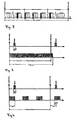
- FIG. 2 shows the frame structure preferably selected in this embodiment for the synchronization signal.
- the frame itself is divided into a synchronization area, a neighboring node area and a data area.
- the individual beacon slots are arranged in the synchronization area.
- the beacon slot assignment of the adjacent nodes is communicated.
- the actual data communication of the network takes place in the data area.
- Each node is identifiable at a given time by its hop count h with 0 ⁇ h ⁇ n and the beacon slot s with 0 ⁇ ssk.
- the highest hop count value in the FIG. 2 example is n
- the highest beacon slot value is k.
- the node marked by h and s sends its beacon in Beaconslot s and layer h of the synchronization area.
- the node is assigned a slot in each of the three frame areas, which slot is determined by the layer h and the beacon slot s of the respective node. Because the layers in the regions are sorted in ascending order, the beacon propagates in a short time to the last layer n of the network.
- a node If a node has collected this information from all neighbors, it can determine its optimal predecessor and a free beacon slot. This creates a collision-free network with balanced ramifications to the central node.
- the nodes alternate frame by frame with the transmission of neighboring node information.
- the beacon slots occupied in the synchronization area determine when which node sends the neighboring node information.
- Each node synchronized to the central node receives the beacon of its predecessor or a neighbor in a given beacon slot and transmits its own beacon with a synchronization signal.
- a node synchronizes to the frame beginning. The synchronization takes place exclusively through the beacons in the beacon slot and is thus independent of the concept of data transmission.
- the nodes can send data packets to their neighbors.
- the values for Hop Count and Beaconslot can be used to structure the data area to reduce collisions.
- the method for data transmission itself is largely arbitrary in the given framework and known to the person skilled in the art.
- the method is based on the rule that each node is responsible for synchronizing itself and finding the best path to the base. Synchronization and route optimization are decentralized in the nodes. The following rules apply:
- An unsynchronized node is initially in the so-called sniff mode, i. a mode by not sending but trying to receive a synchronization signal with a beacon to synchronize.
- sniff mode i. a mode by not sending but trying to receive a synchronization signal with a beacon to synchronize.
- FIG. 3 a process variant of the sniff mode is shown.
- FIG. 3 illustrates the time frame of a frame defined by the frame start and frame period.
- the readiness for reception of the node is indicated by the black time bar overlapping the frame period.
- the black time bar represents the time interval of t sniff , max .
- FIG. 4 shows analogous to FIG. 3 a frame and a beacon transmitted therein in a time interval t sync .
- the receptivity of the node is also represented by the black time bars. If the receiver of the non-synchronized node can only be active for a short time, it periodically hears the maximum possible reception duration in this variant and then recharges its capacities.
- the node As soon as the node receives a beacon, it synchronizes to the beginning of the frame for all procedures. If several neighbors send their beacon in a frame period without collision, the synchronization time is shortened because the reception probability multiplies by the number of neighbors.
- Unsuccessful synchronization requires a lot of energy because the receiver has been active for at least a full frame period without successfully completing the synchronization.
- the next attempt after a failure may only take place after days. Only then can a long battery life be guaranteed.
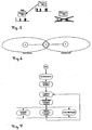
- FIG. 5 illustrates that in the present embodiment, a node sends out a synchronization signal only if it has received a beacon from its selected predecessor. This ensures both a common time base for the entire network and a continuous connection to the central node.
- node 1 has received a beacon from its selected predecessor, node 0.
- node 1 in turn sends out a synchronization signal.
- the beacon of the selected predecessor is received in each frame period.
- each node in the background scans all beacon slots or the corresponding data signals in the neighborhood area to determine new neighbors. So he can optimize his route to the central node or immediately select another neighbor from his list in case of failure of the selected predecessor.
- To optimize the communication structure is selected by each node of the predecessor of (, S ignal Received S trength I ndication RSSI) value having the lowest hop count value, the least successors and the highest received signal strength. The hop count value takes precedence over the successor number and has priority over the received signal strength. If a better neighbor is found, it is selected as the predecessor and the own hop count value is adjusted accordingly.
- the node announces the change in the beacon.
- the followers receive the announcement and try to receive the beacon on the new beacon slot. This preserves the existing communication channels. Other neighbors only notice that a new beacon slot is being used. If the identifier of the node does not appear in a new beacon slot, the node has failed or is taken off the network.
- FIG. 6 illustrates the hidden node problem. Shown are the nodes A, B and C as well as the radio range of nodes A and C. If node B is in the middle of two neighbors A and C and A and C in the same beacon slot send their beacon, then the beacons collide at the node B, without the nodes A or C can notice. In an extreme case, the node B can neither be reached by C nor by A.
- a node is preferably maintained its beacon slot for at least two synchronization phases, as in a shorter change of the beacon slot no systematic synchronization of an unsynchronized node is possible.
- the selection of the new Beaconslots takes place according to the criteria described above.
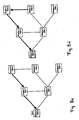
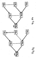
- the Figures 8a - 8g showing structure of the corresponding communication structures in a network consisting of the five nodes with the associated node numbers 0 to 5.
- the nodes are shown as rectangular boxes in which the node number and the current beacon slot are specified.
- the basically possible radio links are shown as thin connecting lines.
- the actually selected communication connections are marked with thicker arrows.
- the central node has the node number 0.
- FIG. 8a shows as a thin connecting lines, the principle possible communication links between the individual nodes due to the respective overlapping transmitting and receiving areas of each node.
- the base node sends a synchronization signal with a beacon in beacon slot 0. All other nodes are unsynchronized and try to receive a beacon in sniff mode.
- FIG. 8b time that node 1 received the beacon of the base node and has synchronized to the beginning frame.
- the predecessor selected by the node 1 is the central node.
- the hop count value of node 1 is thus 1. Since beacon slot 0 is already occupied by the central node, node 1 sends its beacon to beacon slot 1.
- FIG. 8c shows that the node 2 has synchronized with the synchronization signal transmitted by node 1 and has selected node 1 as predecessor.
- FIG. 8d shows that node 3 has synchronized to node 2 and has chosen beacon slot 0 for the transmission of its own beacon. This is possible because the beacon slot 0 is neither used by the direct neighbor (node 2) nor the next but one neighbor (node 1) of node 3. Thus, both from the point of view of node 0 and node 3, a dual use of the beacon slot 0 is protected to the next but one neighbor.
- the optimal one over node 4 can not yet be found by node 3, since node 4 is not yet synchronized, therefore it does not send its own beacon and thus is not yet known to node 3.
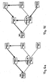
- FIG. 8d shows that node 3 has synchronized to node 2 and has chosen beacon slot 0 for the transmission of its own beacon. This is possible because the beacon slot 0 is neither used by the direct neighbor (node 2) nor the next but one neighbor (node 1) of node 3. Thus, both from the point of view of node 0 and node 3, a dual use of the beacon slot 0 is protected to the next but
- node 4 receives synchronization signals from the node 0 as well as from node 3 with the beacon slot 0. This creates collisions in node 4, so that neither node 0 nor node 3 is visible for node 4 (hidden node problem).
- the only node visible to node 4 is node 1.
- Node 4 therefore synchronizes to node 1 and consequently sends its beacon to beaconslot 3, since node 4 can see from synchronization signal of node 1 that node 1 occupies beacon slot 1 and the neighbors of node 1 (node 0 and node 2) occupy the beacon slots 0 and 2.
- a sensor node first synchronizes to the first beacon that it receives in sniff mode and specifies its predecessor. This means that the sensor node is time-synchronized with the already active network and can now selectively individual in each cycle Listen to beaconslots to find a more suitable predecessor (beacon). To ensure that this does not take too long, a time-synchronous sensor node searches a larger number of beacon slots in each cycle with pauses lasting about 60 ms. After n cycles, the sensor node has listened to all beacon slots and is synchronized to the optimal beacon. Each sensor node that has finally synchronized to a beacon sends a Sync_ind message to the central node for confirmation. Theoretically, this can already be done after the sensor node has synchronized to the first beacon.
- the central node After a certain number of cycles, the central node has received all the identifiers of the synchronized sensor nodes of a layer. The central node then appoints a sensor node per layer and housing cluster to the repeater node and assigns each repeater node a different beacon slot greater than 1.
- the central node first appoints the repeater nodes, which however only begin to send their beacon almost simultaneously after a later broadcast command. This creates, for example, in a ten-story house with ten apartments per floor, 100 repeater nodes. There may be a few more if a dwelling is only partially covered by a lower layer beacon. It is advantageous in this case in the apartment part, which then belongs to the next higher layer, nor provide an additional repeater node.
- Each repeater node regularly sends its beacon in the beacon slot assigned to it.
- the remaining sensor nodes which have not been designated as a repeater node, communicate via a beacon node of the next lower sphere with the central node.
- the remaining sensor nodes of a housing cluster ie all sensor nodes of a dwelling that did not become repeater nodes, synchronize to the repeater node with their dwelling identifier.
- This also has energetic advantages, since within a dwelling the communication link better than over a floor.
- the data transmission of the sensor nodes takes place via their respective repeaters and the path of the repeater nodes in the individual layers which has been defined during the synchronization.
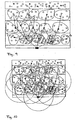
- FIG. 9 schematically branches the distribution of sensor nodes in a 4-storey building.
- the individual sensor nodes (white circles) are assigned to the floors of individual apartment clusters. In each housing cluster, a sensor node was selected as a repeater node. There is a communication structure (black arrows) between the repeater nodes, which enables the communication of the repeater nodes with the central node on the ground floor of the building.
- the individual sensor nodes always select the repeater node in their respective housing cluster for their communication with the central node, for example as predecessors.
- FIG. 10 differs from Rick in that the transmission and reception ranges of individual repeater nodes are illustrated by circles.
- Each sensor node in the transmission area of the central node receives the beacon of the central node (hop count 0), synchronizes to this and responds to the master with a Sync_ind message in a data slot.
- the beacon can max. 8 - 10 ms long. With a data rate of 100 kbaud and a Manchester coding, this corresponds to approximately 50 - 62 bytes, which are available for a beacon. Theoretically, one could also refrain from occupying the beacon slots again after a few hops or layers, but one could have a separate beacon slot for each repeater node. In this example case, there would be a 1-2 second long beacon frame after a repeater count of 100-200. This method would be particularly useful in the following alternative case.
- beacon slot was about 60-70 ms long and you forgive the beacon slots in ascending order.
- Each predecessor repeater node sends in a lower beacon slot. Then each repeater node in a beacon slot can receive the beacon of its predecessor repeater node and send its own beacon in one of the next beacon slots. This allows commands to be transmitted very quickly upwards. You would, however, depending on the number of repeaters and exact slot length a very long beacon frame of about 6-14 seconds in length.
- the long beacon slot times are in this case due to the fact that it is theoretically possible for a beacon to be received in one slot and to be forwarded directly in the next slot. After receiving the beacon, however, a charging time of about 50-60 ms is required. If you can guarantee that there are always at least 5 slots in the slot sequence, you can also work with 10 ms slots.
- the data transmission in the network is preferably based on a contention-based method.
- the second embodiment describes the stepwise synchronization of a bidirectional wireless read-out network, which is subsequently kept synchronous. Due to a special syntax, each sensor node receives a unique identifier during assembly in an apartment, which contains the number of the apartment as well as the corresponding floor. This allows a logical clustering of flats. By naming beacon repeater nodes within a logical cluster (dwelling), a hierarchical structure of the system automatically results and the routing paths for the communication are determined. In addition, it is conceivable to organize the beacon repeater nodes in a higher-level network. To optimize the power consumption, the repeater task should be periodically transferred to neighboring nodes.
Landscapes
- Engineering & Computer Science (AREA)
- Computer Networks & Wireless Communication (AREA)
- Signal Processing (AREA)
- Mobile Radio Communication Systems (AREA)
- Synchronisation In Digital Transmission Systems (AREA)
- Communication Control (AREA)
- Small-Scale Networks (AREA)
Abstract
Description
Die Erfindung bezieht sich auf ein Verfahren zur Bildung eines synchronisierten Netzwerkes zur drahtlosen Kommunikation zwischen Sende-/Empfängereinheiten, den so genannten Knoten (KN) und einer zentralen Sende/Empfängereinheit, dem so genannten Zentralknoten (ZKN) in einem Multihop Netzwerk. Multihop Netzwerke finden in vielfältiger Weise im Bereich der Kommunikationstechnik Anwendung, bspw. bei der Überwachung von Infrastrukturelementen oder der Umweltüberwachung.The invention relates to a method for forming a synchronized network for wireless communication between transceiver units, the so-called node (KN) and a central transceiver unit, the so-called central node (ZKN) in a multihop network. Multihop networks are used in many ways in the field of communication technology, for example in the monitoring of infrastructure elements or environmental monitoring.
Ein Multihop Netzwerk besteht grundsätzlich aus einer Vielzahl von Netzwerkknoten, die jeweils zumindest eine Sende-/ Empfangseinrichtung und eine Prozessoreinheit aufweisen. In Multi Hop Netzwerken werden Daten typischerweise von einem ersten Netzwerkknoten, der Datenquelle, über eine Anzahl als Relaisstationen dienende weitere Netzwerkknoten, so genannte Zwischenknoten zu einem zweiten Netzwerkknoten, der Datensenke, übertragen. Dabei sind der erste sowie der zweite Knoten grundsätzlich beliebig wählbar. Somit wird in einem Multi Top Netzwerk ein Datenaustausch zwischen Netzwerkknoten möglich, deren Sende- und Empfangsbereiche sich nicht überlappen, d.h. die keine direkte Datenkommunikation miteinander herstellen können. Dabei kann jeder Netzwerkknoten Datenquelle, Datensenke als auch Relaisstation sein. Allerdings müssen die einzelnen Netzwerknoten hierfür derart zueinander positioniert sein, dass sich im Sende-/ Empfangsbereichs eines Netzwerkknotens mindestens ein weiterer Netzwerkknoten befindet, so dass dadurch eine vermaschte Kommunikationsstruktur entstehen kann.A multihop network basically consists of a multiplicity of network nodes, each of which has at least one transmitting / receiving device and one processor unit. In multi-hop networks, data is typically transmitted from a first network node, the data source, to a second network node, the data sink, via a number of other network nodes serving as relay stations, called intermediate nodes. In principle, the first and second nodes can be selected arbitrarily. Thus, in a multi-top network, data exchange between network nodes becomes possible whose transmission and reception ranges do not overlap, ie which can not establish direct data communication with each other. Each network node can do this Data source, data sink and relay station. However, the individual network nodes for this purpose must be positioned relative to one another such that at least one further network node is located in the transmission / reception area of a network node, so that a meshed communication structure can thereby be created.
Ein Datenaustausch in einem Multi Hop Netzwerk erfolgt typischerweise im Wege der bidirektionalen drahtlosen Kommunikation, insbesondere im Wege der Funkkommunikation. Für einige Anwendungen können ein oder mehrere Netzwerkknoten durch von ihnen zu erfüllende zusätzliche Funktionen gegenüber den weiteren Netzwerkknoten ausgezeichnet sein. Dient bspw. ein Netzwerkknoten als zentrale Datensenke im Multihop Netzwerk, so ist dieser gegenüber den anderen Netzwerkknoten durch diese Funktion ausgezeichnet und wird im folgenden als Zentralknoten bezeichnet. Selbstverständlich kann dem Zentralknoten auch eine andere und/oder weitere zusätzliche Funktionen zugeordnet sein.A data exchange in a multi-hop network typically takes place by way of bidirectional wireless communication, in particular by way of radio communication. For some applications, one or more network nodes may be distinguished by additional functions to be performed by them over the other network nodes. If, for example, a network node serves as the central data sink in the multihop network, then this is distinguished from the other network nodes by this function and is referred to below as the central node. Of course, the central node can also be assigned a different and / or further additional functions.
Nachteilig an den heute bekannten Verfahren zur Synchronisation und Kommunikation von Multihop Netzwerken ist der erhebliche Rechenaufwand bei den einzelnen Netzwerkknoten zum Aufbau, zur Aufrechterhaltung, zur stetigen Optimierung des Netzwerks und zur Datenkommunikation innerhalb des Netzwerks, sowie insbesondere der damit einhergehende hohe Stromverbrauch bei den einzelnen Netzwerkknoten.A disadvantage of the currently known method for synchronization and communication of multihop networks is the considerable computational effort at the individual network nodes to build, to maintain, for continuous optimization of the network and for data communication within the network, and in particular the associated high power consumption at the individual network nodes ,
Die Stromversorgung der einzelnen Netzwerkknoten erfolgt in vielen Anwendungen durch eine Batterie. Um die einzelnen Netzwerkknoten möglichst lange mit Batterie zu betreiben, muss daher der Stromverbrauch für den Betrieb möglichst gering sein. Auch für Zentralknoten, die viele Datenpakete weiterleitet, muss eine bestimmte Lebensdauer erreicht werden. Dies erfordert einen geringen Duty Cycle. Der Duty Cycle ist das Verhältnis von Aktivzeit, d.h. aktiver Kommunikation, zu Schlafzeit, d.h. nicht aktiver Kommunikation eines Knotens. Weiterhin nachteilig ist, dass bei den entsprechenden heute bekannten Verfahren durch Kollisionen bei der Funkkommunikation das an sich bekannte so genannte "Hidden Node" Problem auftreten kann. Dadurch ist der "Hidden Node", d.h. der entsprechende Knoten, vom Netzwerk nicht erreichbar.The power supply of the individual network nodes takes place in many applications by a battery. To operate the individual network nodes as long as possible with battery, therefore, the power consumption for operation must be as low as possible. Even for central nodes, which forwards many data packets, a certain lifespan must be achieved. This requires a low duty cycle. The duty cycle is the ratio of active time, i. active communication, at sleep time, i. non-active communication of a node. A further disadvantage is that the so-called "hidden node" problem known per se can occur in the corresponding methods known today as a result of collisions in the radio communication. As a result, the "hidden node", i. the corresponding node, not reachable by the network.
Die
Die
Die
The
The
Die Aufgabe der vorliegenden Erfindung besteht darin, ein Verfahren zur kollisionsfreien Synchronisation und Kommunikation in einem Multihop Netzwerk anzugeben, das sich durch einen geringen Stromverbrauch sowie durch einen niedrigen Duty Cycle auszeichnet. Das Verfahren soll die aufgeführten Probleme bisheriger Verfahren zumindest größtenteils vermeiden. Insbesondere soll es möglich sein redundante Kommunikationswege zu erzeugen, um die Ausfallsicherheit zu erhöhen. Weiterhin soll das "Hidden Node" Problem vermieden werden.The object of the present invention is to provide a method for collision-free synchronization and communication in a multihop network, which is characterized by a low power consumption and by a low duty cycle. The method should at least largely avoid the listed problems of previous methods. In particular, it should be possible to generate redundant communication paths in order to increase the reliability. Furthermore, the "hidden node" problem should be avoided.
Die Aufgabe wird mit dem Verfahren gemäß Patentanspruch 1 gelöst. Vorteilhafte Ausgestaltungen des Verfahrens sind Gegenstand der Unteransprüche oder lassen sich der nachfolgenden Beschreibung sowie der Ausführungsbeispiele entnehmen.The object is achieved by the method according to
Das erfindungsgemäße Verfahren zeichnet sich durch folgende Verfahrensschritte aus:
- a) Aussenden eines Synchronisationssignals durch den Zentralknoten oder einen bereits synchronisierten Knoten, wobei ein durch den das Synchronisationssignal sendenden Knoten festgelegter Slot im Frame des Synchronisationssignals, der so genannte Beaconslot, mit einem Datenpaket, dem so genannten Beacon, belegt wird und zumindest der Hop Count Wert des sendenden Knotens im Frame des Synchronisationssignals übertragen wird, und für alle bereits synchronisierten Nachbarknoten des sendenden Knotens, die dem sendenden Knoten bekannt sind Übertragen der jeweiligen Beaconslots und Hop Count Werte im Frame des Synchronisierungssignals oder als separates Datensignal durch den sendenden Knoten,
- b) Empfangen des Synchronisationssignals sowie der in Zusammenhang damit übermittelten Daten durch einen im Sende-/Empfangsbereich des sendenden Knotens liegenden ersten Knotens,
- c) Synchronisieren des ersten Knotens auf das Synchronisierungssignal,
- d) Ermitteln der Nachbarn des ersten Knotens sowie deren jeweiliger Beaconslotbelegung und Hop Count Werte durch den ersten Knoten,
- e) Festlegen des Vorgängers des ersten Knotens im Netzwerk durch den ersten Knoten auf Basis vorgegebenen Kriterien,
- f) Speichern der mit dem Synchronisationssignal sowie in Zusammenhang damit empfangenen sowie daraus ermittelten Daten durch den ersten Knoten,
- g) Wiederholen der Schritte a) bis f) zumindest bis zur Synchronisation aller Knoten.
- a) transmitting a synchronization signal by the central node or an already synchronized node, wherein a by the synchronizing signal transmitting node fixed slot in the frame of the synchronization signal, the so-called beacon slot, with a data packet, the so-called beacon, is occupied and at least the hop count Value of the transmitting node is transmitted in the frame of the synchronization signal, and for all already synchronized neighboring nodes of the transmitting node, which are known to the transmitting node transmitting the respective beacon slots and hop count values in the frame of the synchronization signal or as a separate data signal by the transmitting node,
- b) receiving the synchronization signal and the data transmitted in connection therewith through a first node located in the transmission / reception area of the transmitting node,
- c) synchronizing the first node to the synchronization signal,
- d) determining the neighbors of the first node as well as their respective beacon slot assignment and hop count values by the first node,
- e) determining the predecessor of the first node in the network by the first node based on predetermined criteria,
- f) storing the data received by the synchronization signal as well as in connection therewith and determined therefrom by the first node,
- g) repeating steps a) to f) at least until the synchronization of all nodes.
Das erfindungsgemäße Verfahren zur Synchronisation und Kommunikation basiert auf einem Multi Hop Netzwerk, das einen Zentralknoten und mehrere Knoten aufweist. Das Netzwerk kann unbegrenzt groß sein, d.h. das Netzwerk kann beliebig viele Knoten umfassen. Das Verfahren dient zudem der Aufrechterhaltung der Synchronisation im Normalbetrieb des Netzwerks.
Der Zentralknoten wie auch die Knoten weisen jeweils eine Sende-/Empfängereinheit, eine Speichereinheit sowie eine Prozessoreinheit auf. Die einzelnen Knoten können ortsfest oder mobil sein. Die Stromversorgung der Konten und des Zentralknotens erfolgt über Akkumulatoren, das Stromnetz oder wird vor Ort bspw. durch Solarzellen erzeugt. Der Zentralknoten und die Knoten sind dabei räumlich derart zueinander positioniert, dass sich im Sende-/Empfangsbereich jedes Knotens mindestens ein weiterer Knoten oder der Zentralknoten befindet. Jeder Knoten steht damit zumindest mit einem weiteren Knoten oder dem Zentralknoten in direkter Kommunikationsverbindung. Die Kommunikation zwischen einem Knoten, der sich außerhalb des Sende-/Empfangsbereich des Zentralknotens befindet und dem Zentralknoten erfolgt unter Einbeziehung weiterer Knoten als Relaisstationen (so genannte Zwischenknoten) über eine Multi Hop Kommunikation. Damit ist es möglich, dass Knoten, die nicht über eine direkte Kommunikationsbeziehung zum Zentralknoten verfügen, ihre Daten über die Zwischenknoten an den Zentralknoten übermitteln.The method according to the invention for synchronization and communication is based on a multi-hop network which has a central node and a plurality of nodes. The network can be infinitely large, ie the network can comprise any number of nodes. The method also serves to maintain synchronization during normal operation of the network.
The central node as well as the nodes each have a transceiver unit, a memory unit and a processor unit. The individual nodes can be stationary or mobile. The power supply of the accounts and the central node via accumulators, the power grid or locally generated, for example, by solar cells. The central node and the nodes are spatially positioned relative to one another in such a way that at least one further node or the central node is located in the transmission / reception area of each node. Each node is thus in direct communication with at least one other node or the central node. The communication between a node that is outside the transmission / reception area of the central node and the central node takes place with the inclusion of additional nodes as relay stations (so-called intermediate nodes) via a multi-hop communication. This makes it possible for nodes that do not have a direct communication relationship to the central node communicate their data via the intermediate nodes to the central node.
Der Zentralknoten zeichnet sich gegenüber den anderen Knoten im Netzwerk dadurch aus, dass er als Bezugspunkt für die Kommunikationswege im Netzwerk und zudem als Zeitbasis für die Synchronisation der Netzwerkknoten, und damit des gesamten Netzwerkes dient. Nach erfolgter Synchronisation des Netzwerkes leiten daher alle Knoten ihre Zeitbasis vom Zentralknoten ab. Selbstverständlich können vom Zentralknoten weitere Funktionen im Netzwerk übernommen werden, bspw. kann er als zentrale Datensenke dienen oder er kann das Netzwerk steuernde Aufgaben haben. Durch die Zusatzfunktionen des Zentralknotens kann sich die Hardwareausstattung des Zentralknotens von den anderen Knoten, bspw. durch einen größeren Speicher oder eine höhere Rechenleistung, unterscheiden.The central node is distinguished from the other nodes in the network in that it serves as a reference point for the communication paths in the network and also as a time base for the synchronization of the network nodes, and thus of the entire network. After synchronization of the network, therefore, all nodes derive their time base from the central node. Of course, can be taken over from the central node more functions in the network, for example. He can serve as a central data sink or he can have the network controlling tasks. Due to the additional functions of the central node, the hardware equipment of the central node from the other nodes, for example, by a larger memory or higher computing power, differ.
Für die weiteren Ausführungen sollen folgende begrifflichen Festlegungen gelten:
- Alle Knoten, die innerhalb der Sende-/Empfangsreichweite eines Knotens liegen, werden als dessen Nachbarn bezeichnet.
- Die für eine Kommunikation zwischen einem Knoten und dem Zentralknoten erforderliche und um Eins erhöhte Anzahl der Zwischenknoten bezeichnet den so genannten Hop Count Wert dieses Knotens.
- Alle Knoten mit gleichem Hop Count Wert bilden eine so genannte Schicht.
- In einer gegebenen Kommunikationskette mit mehreren Zwischenknoten sei ein Zwischenknoten mit dem Hop Count Wert i herausgegriffen. Der Zwischenknoten der Kommunikationskette mit dem Hop Count Wert i-1 wird als Vorgänger des Zwischenknotens mit dem Hop Count Wert i, derjenige mit dem Hop Count Wert i+1 als dessen Nachfolger bezeichnet.
- Der Zentralknoten und die weiteren Knoten des Netzwerkes bilden in ihrer Gesamtheit die Knoten. Kommt es in der folgenden Beschreibung auf eine Unterscheidung des Zentralknotens von den anderen Knoten an, so wird der Begriff "Zentralknoten" explizit verwandt, wird auf die Gesamtheit aller Knoten, d.h. einschließlich des Zentralknotens, abgestellt, so wird der allgemeine Begriff "Knoten" verwandt.
- All nodes that are within the send / receive range of a node are called its neighbors.
- The number of intermediate nodes required for communication between a node and the central node and increased by one denotes the so-called hop count value of this node.
- All nodes with the same hop count value form a so-called layer.
- In a given communication chain with multiple intermediate nodes, let's say an intermediate node with the hop Count value i picked out. The intermediate node of the communication chain with the hop count value i-1 is called the predecessor of the intermediate node with the hop count value i, the one with the hop count value i + 1 as its successor.
- The central node and the other nodes of the network together form the nodes. If, in the following description, a distinction is made between the central node and the other nodes, then the term "central node" is explicitly used, and the whole of all nodes, ie including the central node, is used, then the general term "node" is used ,
Die
Der
In analoger Weise ergeben sich, die in
Die Kommunikation zwischen den einzelnen Knoten im Multi Hop Netzwerk beruht auf einer drahtlosen Datenübertragung in Frames, die in definierte Slots unterteilt sind. Vorzugsweise finden dabei bidirektionale Kommunikationsverfahren, insbesondere Funkverfahren Anwendung, die folgende Datenübertragungsprotokolle verwenden: Time Division Multiple Access (TDMA), Frequency Division Multiple Access (FDMA), Code Division Multiple Access (CDMA). Unterteilungen des Frames in Datenbereiche, vorzugsweise in einen Synchronisations-, Nachbarknoten- und Datenbereich, kommen je nach Anwendung in Betracht, um so bspw. gleichzeitig normale Kommunikationsdaten und Daten, die der Synchronisation, der Aufrechterhaltung sowie der Optimierung der Netzwerkstruktur dienen, in einem Frame zu versenden. In einer weiteren vorteilhaften Ausgestaltung des Verfahrens kann durch eine Parametrierung die Framestruktur, d.h. die Framedauer, die Anzahl der Slots oder die Unterteilung des Frames in Bereiche, das Netzwerk im laufenden Betrieb an besondere Bedingungen angepasst werden.The communication between the individual nodes in the multi-hop network is based on wireless data transmission in frames, which are subdivided into defined slots. In this case, bidirectional communication methods, in particular radio methods, are preferably used, the following data transmission protocols Use: Time Division Multiple Access (TDMA), Frequency Division Multiple Access (FDMA), Code Division Multiple Access (CDMA). Subdivisions of the frame into data areas, preferably in a synchronization, neighboring node and data area, come into consideration depending on the application, for example, at the same time normal communication data and data that serve the synchronization, maintenance and optimization of the network structure, in a frame to send. In a further advantageous embodiment of the method, the frame structure, ie the frame duration, the number of slots or the subdivision of the frame into areas, the network can be adapted during operation to special conditions by a parameterization.
Erfindungsgemäß wird bei dem Verfahren vom Zentralknoten oder von einem bereits synchronisierten Knoten ein Synchronisationssignal ausgesandt, wobei ein durch den sendenden Knoten festgelegter Slot im Frame des Synchronisationssignals, der so genannte Beaconslot, belegt wird. Ein einmal von einem sendenden Knoten festgelegter Beaconslot wird grundsätzlich auch für die Aussendungen weiterer Synchronisationssignale durch den jeweiligen Knoten beibehalten. Ausnahmen hiervon werden nachfolgend gesondert beschrieben.According to the invention, in the method, a synchronization signal is transmitted from the central node or from an already synchronized node, wherein a slot defined by the transmitting node in the frame of the synchronization signal, the so-called beacon slot, is occupied. A beacon slot once defined by a transmitting node is in principle also retained for the transmissions of further synchronization signals by the respective node. Exceptions to this will be described separately below.
Weiterhin werden mit jedem Synchronisierungssignal oder als separat gesendetes Datenpaket in Zusammenhang mit einem Synchronisierungssignal zumindest folgende Daten ausgesandt: für alle bereits synchronisierten Nachbarn des sendenden Knotens, die jeweils durch diese Nachbarn bereits belegten Beaconslots sowie die jeweiligen Hop Count Werte dieser Nachbarn. In einer vorteilhaften Fortbildung des Verfahrens werden zusätzlich jeweils auch die von den bereits synchronisierten direkten Nachbarn eines sendenden Knotens belegten Beaconslots sowie deren Hop Count Werte übertragen. In einer weiteren Fortbildung des Verfahrens wird zusätzlich die Anzahl der Nachfolger des sendenden Knotens im Netzwerk übertragen.Furthermore, at least the following data are sent with each synchronization signal or as a separately transmitted data packet in connection with a synchronization signal: for all already synchronized neighbors of the transmitting node, the beacons slots already occupied by these neighbors as well as the respective hop count values of these neighbors. In an advantageous development of the method, the beacon slots occupied by the already synchronized direct neighbors of a transmitting node and their hop count values are additionally transmitted in each case as well. In a further development of the method, the number of successors of the sending node in the network is additionally transmitted.
Der einem Knoten derart zugeordnete Beaconslot sowie der Hop Count Wert haben im Netz zu einem Zeitpunkt die Funktion einer individuellen Kennung, die für die direkten Nachbarn eindeutig ist. Weiterhin wird dadurch eine kollisionsfreie Kommunikation zwischen den Knoten ermöglicht. Eine zusätzliche individuelle Kennung jedes Knotens im Netz ist somit nicht erforderlich aber selbstverständlich möglich und für bestimmte Anwendungen des Verfahrens sogar erforderlich.The beacon slot thus assigned to a node and the hop count value have the function of an individual identifier in the network at one time, which is unique for the direct neighbors. Furthermore, this enables collision-free communication between the nodes. An additional individual identifier of each node in the network is thus not required but of course possible and even required for certain applications of the method.
Die Synchronisationssignale bzw. die damit in Zusammenhang stehenden Datenpakete werden von allen Nachbarn des sendenden Knotens, d.h. sowohl von den bereits synchronisierten als auch von den noch nicht synchronisierten Nachbarn, empfangen und jeweils ausgewertet. Die noch nicht synchronisierten Nachbarn erhalten mit dem Synchronisierungssignal eine Zeitbasis auf die eie sich synchronisieren. Die bereits synchronisierten Nachbarn des Knotens benutzen das Synchronisationssignal in vorteilhafter Weise für eine Überprüfung ihrer Synchronisation.The synchronization signals or related data packets are received by all neighbors of the sending node, i. from both the already synchronized and the not yet synchronized neighbors, received and evaluated. The not yet synchronized neighbors receive with the synchronization signal a time base on which they synchronize themselves. The already synchronized neighbors of the node advantageously use the synchronization signal to verify their synchronization.
Bei der Auswertung der empfangenen Daten durch einen Knoten werden zumindest die aktuellen lokalen Nachbarschaftsbeziehungen des jeweiligen Knotens inklusive der in der lokalen Umgebung bereits bestehenden Kommunikationsstruktur, d.h. insbesondere die jeweilige Beaconslotbelegung und die Hop Count Werte seiner bereits synchronisierten Nachbarn ermittelt und gespeichert. In vorteilhafter Weise werden zusätzlich auch die jeweilige Beaconslotbelegung und die Hop Count Werte seiner bereits synchronisierten übernächsten Nachbarn ermittelt und gespeichert.When evaluating the received data by a node, at least the current local Neighborhood relations of the respective node, including the already existing in the local environment communication structure, ie in particular the respective Beaconslotbelegung and the hop count values of its already synchronized neighbors determined and stored. In addition, the respective beacon slot assignment and the hop count values of its already synchronized next but one neighbors are advantageously also determined and stored.
Infolge der mit dem Synchronisationssignale übertragenen aktuellen Nachbarschaftsdaten erkennt ein noch nicht synchronisierter Knoten, welche Beaconslots durch seine Nachbarn bereits belegt sind. Er ermittelt selbständig einen Beaconslot für die Aussendung seines eigenen Synchronisierungssignals, der zumindest bis zu seinen übernächsten Nachbarn unbelegt ist. So wird jeder belegte Beaconslot grundsätzlich bis zur übernächsten Schicht geschützt. In einer Fortbildung des Verfahrens wird neben der Beaconslotbelegung der direkten Nachbarn auch diejenige der übernächsten Nachbarn des Knoten berücksichtigt. Durch die damit mögliche kollisionsfreie Kommunikation wird das so genannte "Hidden Node" Problem vermieden, wie später noch eingehender erläutert wird.
Auf Basis der ermittelten aktuellen Nachbarschaftsdaten und/oder weiterer Daten, wie bspw. der Signalstärke des empfangenen Synchronisationssignals, erfolgt, unter Zugrundelegung vorgegebener Kriterien, durch den jeweiligen Knoten die Festlegung seines Vorgängers im Netzwerk. Dadurch entsteht innerhalb des Multi Hop Netzwerkes eine durch die vorgegebenen Kriterien bestimmte Kommunikationsstruktur. Vorzugsweise wird jeder Knoten veranlasst, denjenigen Knoten als Vorgänger zu wählen, welcher:
- a) in seiner Kommunikationskette die wenigsten Zwischenknoten zum Zentralknoten hat, d.h. welcher den geringsten Hop Count Wert hat, oder
- b) die wenigsten Nachfolger hat, oder
- c) dessen Signale mit der größten Signalstärke vom Knoten empfangen werden.
Based on the determined current neighborhood data and / or other data, such as the signal strength of the received synchronization signal, based on predetermined criteria, by the respective node, the determination of its predecessor in the network. This creates a communication structure determined by the given criteria within the multi-hop network. Preferably, each node is made to choose as its predecessor those nodes which:
- a) has in its communication chain the few intermediate nodes to the central node, ie which has the lowest hop count value, or
- b) has the least successors, or
- c) whose signals with the highest signal strength are received by the node.
Es können bei der Wahl des Vorgängers weitere Kriterien, einbezogen und/oder die aufgeführten sowie die weiteren Kriterien beliebig kombiniert werden. Durch die Festlegung des Vorgängers wird von jedem Knoten seine Kommunikationskette zum Zentralknoten ausgewählt.It can in the election of the predecessor more criteria included, and / or listed and the other criteria can be combined arbitrarily. By defining the predecessor, each node selects its communication chain to the central node.
Mit der entsprechenden Auswahl des Vorgängers weist sich der Knoten des weiteren selbst einen um die Zahl Eins höheren Hop Count Wert als der Hop Count Wert des ausgewählten Vorgängers zu.With the corresponding selection of the predecessor, the node itself further assigns a hop count value higher by the number one than the hop count value of the selected predecessor.
Im Normalbetrieb, d.h. nachdem alle Knoten synchronisiert sind und der reguläre Datenaustausch im gesamten Netzwerk abläuft, empfängt jeder Knoten weiterhin das Synchronisationssignal seines Vorgängers, um die Synchronisation aufrechtzuerhalten, und verschickt sein eigenes Synchronisationssignal, um seine Nachfolger zu erreichen. Der Knoten tauscht mit seinen Nachbarknoten Datenpakete aus. Im Hintergrund ermittelt er ständig seine aktiven Nachbarn und erkennt so Veränderungen zumindest in der lokalen Netzwerkstruktur.In normal operation, ie after all nodes are synchronized and the regular data exchange is taking place throughout the network, each node continues to receive the synchronization signal of its predecessor to maintain synchronization and sends its own synchronization signal to reach its successors. The node exchanges data packets with its neighboring nodes. In the background, he constantly determines his active neighbors and thus recognizes changes, at least in the local network structure.
Ändern sich die lokalen Nachbarschaftsbeziehungen für einen Knoten für zwei aufeinander folgende von ihm empfangene Synchronisierungssignale, bspw. durch Hinzutreten weiterer synchronisierter Nachbarknoten im Netz oder durch Entfernen oder Versagen von bereits synchronisierten Nachbarknoten, so wird dies vom Knoten durch Vergleich der aktuell empfangenen Nachbarschaftinformationen mit den gespeicherten vorhergehenden Nachbarschaftsinformationen erkannt. Das erfindungsgemäße Verfahren führt dazu, dass sich das Netzwerk auf Veränderungen im Netzwerk stets anpasst. Wird bspw. der Vorgänger eines Knotens aus dem Netz entfernt, so wird der Knoten einen neuen Vorgänger gemäß der vorgegebenen Kriterien bestimmen.
Wurde durch das Verfahren ein bisher nicht synchronisierter Knoten synchronisiert, so trägt er seinerseits durch Aussenden eigener Synchronisationssignale zur Synchronisation weiterer Knoten bei Der Knoten kann nach dem Empfang des ersten Synchronisationssignals bereits an der normalen Datenkommunikation des bereits synchronisierten Multi Hop Netzwerks teilnehmen. Die beschriebenen Verfahrensschritte werden zumindest so oft wiederholt bis alle Knoten im Netzwerk synchronisiert sind. Vorzugsweise wird das Verfahren jedoch parallel zur Normalkommunikation betrieben.If the local neighborhood relationships for a node change for two successive synchronization signals received by it, for example by adding further synchronized neighbor nodes in the network or by removing or failing already synchronized neighboring nodes, this is done by the node by comparing the currently received neighborhood information with the stored ones previous neighborhood information detected. The method according to the invention means that the network always adapts to changes in the network. If, for example, the predecessor of a node is removed from the network, the node will determine a new predecessor according to the predetermined criteria.
Was synchronized by the method a previously non-synchronized node, it contributes in turn by sending its own synchronization signals for synchronization of other nodes The node can already participate in the normal data communication of the already synchronized multi-hop network after receiving the first synchronization signal. The described method steps are repeated at least until all nodes in the network are synchronized. Preferably, however, the method is operated in parallel to the normal communication.
Nach der allgemeinen Beschreibung des erfindungsgemäßen Verfahrens soll nun nochmals auf die konkreten Schritte zu Beginn des Verfahrens eingegangen werden.After the general description of the method according to the invention will now be addressed again to the concrete steps at the beginning of the process.
Zu Beginn der Synchronisierung sendet zunächst nur der Zentralknoten Synchronisationssignale aus. Die anderen Knoten nehmen einen Empfangsmodus (Sniff Modus) ein. Der Zentralknoten kann daher vor der Aussendung seines ersten Synchronisationssignals jeden beliebigen Beaconslot, bspw. den Beaconslot 1, belegen. Für den Zentralknoten beträgt der Hop Count Wert bspw. 0. Da der Zentralknoten zu Beginn der Synchronisation zunächst keinen seiner Nachbarknoten erkennt, sind seinem Synchronisationssignal nur der belegte Beaconslot = 1 sowie der Hop Count Wert = 0 zu entnehmen. Die Nachbarknoten des Zentralknotens empfangen das beschriebene Synchronisierungssignal des Zentralknotens, speichern die dabei übermittelten Daten bzw, werten diese aus und synchronisieren ihre jeweilige Zeitbasis auf die Zeitbasis des Zentralknotens. Anschließend senden die bereits synchronisierten Knoten ihrerseits kollisionsfrei ihr eignes Synchronisierungssignal aus, so dass sich die weiter von dem Zentralknoten entfernt liegenden Knoten synchronisieren können. Dabei werden die jeweils noch freien Beaconslots belegt, d.h. im vorliegenden Beispiel die Beaconslots 2, 3, 4, usw. sowie beim sendenden Knoten vorliegende Nachbarschaftsinformationen übertragen. So überträgt der erste auf den Zentralknoten synchronisierte Knoten (K1) bspw. folgende Daten: durch K1 festgelegter Beaconslot = 2, Hop Count Wert von K1 = 1, sowie die Nachbarschaftsinformation: Nachbar mit Hop Count Wert = 0 und Beaconslot 1. Diese Daten werden von den Nachbarn des K1 empfangen, ausgewertet und gespeichert. Die im Laufe des Verfahrens synchronisierten Nachbarknoten des Zentralknotens bilden so die erste synchronisierte Schicht um den Zentralknoten, die weiter entfernt liegenden die zweite synchronisierte Schicht usw. bis alle Knotensynchronisiert sind. Ist kein Beaconslot mehr frei, so wird der Knoten zu einem Endknoten.At the beginning of synchronization, initially only the central node sends out synchronization signals. The other nodes assume a receive mode (sniff mode). The central node can therefore occupy any beacon slot, for example the
Durch das erfindungsgemäße Verfahren muss nach Empfang eines Synchronisationssignals nur eine begrenzte Zahl von Beaconslots analysiert werden, weil belegte Beaconslots nach drei Schichten durch andere Knoten wieder verwendet werden können. Damit ist das Verfahren sehr energieeffizient und führt zu einem deutlich geringeren Energiebedarf als bisher bekannte Verfahren. Das Verfahren ermöglicht zudem ein Netzwerkabbild, weil alle Nachbarbeziehungen zwischen Knoten zu einem Zeitpunkt grundsätzlich bekannt sind und damit auch zur Überprüfung von Kommunikationswegen dienen können. Weiterhin ergeben sich zusammenfassend durch Anwendung des erfindungsgemäßen Verfahrens folgende Vorteile gegenüber dem Stand der Technik:
- Ein beliebig großes Netzwerk synchronisiert sich auch unter schwierigsten Ausbreitungsbedingungen auf einen Zentralknoten.
- Alle Nachbarknoten werden mit geringstem Energieaufwand entdeckt.
- Indirekte Kollisionen durch Hidden Nodes werden vermieden, da die Informationen welche Beaconslots belegt sind den Nachbarn mitgeteilt werden.
- Es wird eine optimale Kommunikationsstruktur erreicht.
- Das Netzwerk passt sich automatisch Veränderungen, bspw. durch Hinzufügen oder Entfernen von Knoten aus dem Netzwerk oder veränderten Funkausbreitungsbedingungen, an.
- An arbitrarily large network synchronizes itself to a central node even under the most difficult propagation conditions.
- All neighboring nodes are discovered with the least amount of energy.
- Indirect collisions by hidden nodes are avoided, because the information that is occupied by beacons is communicated to the neighbors.
- An optimal communication structure is achieved.
- The network automatically adapts to changes, for example, by adding or removing nodes from the network or changing radio propagation conditions.
Die Erfindung wird nachstehend ohne Beschränkung des allgemeinen Erfindungsgedankens anhand von Ausführungsbeispielen unter Bezugnahme auf die Zeichnungen exemplarisch beschrieben. Es zeigen:
- Fig. 1
- Prinzipschaubildes eines Multi Hop Netzwerkes;
- Fig. 2
- Darstellung des Frames eines Synchronisationssignals, d.h. eines entsprechenden Zeitrahmens mit Synchronisations-, Nachbarschaftsknoten- sowie Datenbereich;
- Fig. 3
- Darstellung eines Zeitrahmens zur Erläuterung einer Version des Sniff Modus;
- Fig. 4
- Darstellung eines Zeitrahmens zur Erläuterung einer weiteren Version des Sniff Modus;
- Fig. 5
- Darstellung zur Erläuterung des Basis Link;
- Fig. 6
- Darstellung zur Erläuterung des Hidden Node Problems;
- Fig. 7
- Verfahrensablauf für einen Knoten;
- Fig. 8
- Aufbau der Kommünikationsstruktur im Netzwerk;
- Fig. 9
- Kommunikationsstruktur zwischen einem Zentralknoten und einer Vielzahl von Sensorknoten über so genannte Repeaterknoten; und
- Fig. 10
- Kommunikationsstruktur wie in
Figur 9 mit Darstellung der Sende-/ Empfangsbereiche einzelner Knoten.
- Fig. 1
- Schematic diagram of a multi-hop network;
- Fig. 2
- Representation of the frame of a synchronization signal, ie a corresponding time frame with synchronization, Nachbarschaftsknoten- and data area;
- Fig. 3
- Representation of a time frame to explain a version of Sniff mode;
- Fig. 4
- Presentation of a time frame to explain another version of sniff mode;
- Fig. 5
- Presentation to explain the Basis Link;
- Fig. 6
- Illustration for explaining the hidden node problem;
- Fig. 7
- Procedure for a node;
- Fig. 8
- Structure of the communication structure in the network;
- Fig. 9
- Communication structure between a central node and a plurality of sensor nodes via so-called repeater nodes; and
- Fig. 10
- Communication structure as in
FIG. 9 with representation of the transmission / reception ranges of individual nodes.
Das erste Ausführungsbeispiel beschreibt eine Ausführungsform des erfindungsgemäßen Verfahrens zur Synchronisation, Kommunikation in einem verteilten Multi Hop Netzwerk, mit einem Zentralknoten und mehreren Knoten. In diesem unbegrenzt großen Multi Hop Netzwerk werden Daten einerseits von den Knoten zum Zentralknoten geschickt werden, andererseits ist auch der umgekehrte Weg möglich. Es kann dabei ein niedriger Duty Cycle von ca. 0,02% zum Senden/Empfangen von Daten realisiert werden, um eine lange Lebensdauern der batteriebetriebenen Sensoren zu gewährleisten. Jeder Knoten entdeckt dabei regelmäßig und mit geringem Energieaufwand alle seine Nachbarknoten. Es wird die optimale Verbindung zu dem Zentralknoten im laufenden Betrieb gefunden und es ist kein manueller Eingriff zur Installation bzw. zum Finden von Ausfallrouten nötig.The first embodiment describes an embodiment of the method according to the invention for synchronization, communication in a distributed multi-hop network, with a central node and a plurality of nodes. In this unlimited multi hop On the one hand, network data will be sent from the nodes to the central node, on the other hand, the reverse way is possible. In this case, a low duty cycle of approximately 0.02% for transmitting / receiving data can be realized in order to ensure a long service life of the battery-operated sensors. Each node discovers all its neighboring nodes regularly and with low energy expenditure. It is the optimal connection to the central node found during operation and there is no manual intervention to install or to find out of failure routes needed.
Die nachfolgend beschriebene Synchronisation des Netzwerkes ist Voraussetzung für viele energiesparende Datenübertragungsverfahren.
Jeder Knoten ist zu einem bestimmten Zeitpunkt durch seinen Hop Count Wert h mit 0 ≤ h ≤ n und dem Beaconslot s mit 0 ≤ s s k identifizierbar. Der höchste Hop Count Wert in dem in
Each node is identifiable at a given time by its hop count h with 0 ≤ h ≤ n and the beacon slot s with 0 ≤ ssk. The highest hop count value in the
Im Datenbereich besitzt jeder Knoten in Schicht h und Slot s einen bidirektionalen Datenslot zur Kommunikation mit seinen Nachfolgern. In dem Beacon legt der jeweilige Knoten die Übertragung zu seinen Nachfolgern oder Vorgängern fest. Optional kann ein Konten damit ein exklusives Senderecht an einen bestimmten Nachfolger vergeben. Im Nachbarknotenbereich werden die Belegungsinformationen der Beaconslots der Nachbarknoten übertragen. Er ist grundsätzlich wie der Synchronisationsbereich aufgebaut, mit dem Unterschied, dass nach drei Schichten die erste Schichtgruppe wieder verwendet wird. Synchronisations- und Nachbarknoteninformationen können optional auch zu einem Paket zusammengefasst werden. In diesem Fall ist der Frame nur in einen Synchronisationsbereich und einen Datenbereich unterteilt. Ein Paket mit Nachbarknoteninformationen enthält wesentliche Informationen zu den Nachbarn eines Knotens, wie:
- durch Nachbarn belegte Beaconslots,
- jeweilige Vorgänger,
- Anzahl der jeweiligen Nachfolger, sowie
- weitere lokale Informationen.
- neighbors occupied by beacons,
- respective predecessors,
- Number of each successor, as well
- more local information.
Hat ein Knoten diese Informationen von allen Nachbarn gesammelt, kann er seinen optimalen Vorgänger und einen freien Beaconslot bestimmen. Dadurch entsteht ein kollisionsfreies Netzwerk mit ausgeglichenen Verästelungen zum Zentralknoten.If a node has collected this information from all neighbors, it can determine its optimal predecessor and a free beacon slot. This creates a collision-free network with balanced ramifications to the central node.
Im Ausführungsbeispiel wechseln sich die Knoten Frame für Frame mit dem Senden der Nachbarknoteninformationen ab. Durch die im Synchronisationsbereich belegten Beaconslots wird festgelegt, wann welcher Knoten die Nachbarknoteninformationen sendet.
Jeder auf den Zentralknoten synchronisierte Knoten empfängt in einem bestimmten Beaconslot den Beacon seines Vorgängers bzw. eines Nachbarn und sendet einen eigenen Beacon mit einem Synchronisationssignal aus. Durch den Empfang eines Beacons im Synchronisationssignal synchronisiert sich ein Knoten auf den Frame Anfang. Die Synchronisierung erfolgt ausschließlich durch die Beacons im Beaconslot und ist somit unabhängig vom Konzept der Datenübertragung.
Im Datenbereich des Frames sind mehrere Datenslots vorgesehen. In diesen Datenslots können die Knoten Datenpakete an ihre Nachbarn senden. Die Werte für Hop Count und Beaconslot können zur Strukturierung des Datenbereichs verwendet werden, um Kollisionen zu reduzieren. Das Verfahren zur Datenübertragung selbst ist im vorgegeben Rahmen weitgehend beliebig und dem Fachmann bekannt.
Optional kann zwischen der Übertragung des Synchronisationsbereichs sowie dem Nachbarknot-enbereich und dem Datenbereich eine Pause liegen, um Sendekapazitäten wieder aufzuladen.In the exemplary embodiment, the nodes alternate frame by frame with the transmission of neighboring node information. The beacon slots occupied in the synchronization area determine when which node sends the neighboring node information.
Each node synchronized to the central node receives the beacon of its predecessor or a neighbor in a given beacon slot and transmits its own beacon with a synchronization signal. By receiving a beacon in the synchronization signal, a node synchronizes to the frame beginning. The synchronization takes place exclusively through the beacons in the beacon slot and is thus independent of the concept of data transmission.
In the data area of the frame several data slots are provided. In these data slots, the nodes can send data packets to their neighbors. The values for Hop Count and Beaconslot can be used to structure the data area to reduce collisions. The method for data transmission itself is largely arbitrary in the given framework and known to the person skilled in the art.
Optionally, there may be a pause between the transmission of the synchronization area and the neighboring emergency area and the data area in order to recharge transmission capacities.
Sind sehr viele Beaconslots bereits belegt, so kann auch auf das Senden eines Synchronisationssignals verzichtet werden. Der jeweilige Knoten wird dann zu einem so genanten Endknoten. Dadurch können allerdings Knoten, die eine Schicht weiter entfernt liegen, unerreichbar werden.
Das Synchronisationssignal enthält:
- den Beaconslot, damit ein Empfänger aus der Empfangszeit den Frameanfang bestimmen kann. Ein Knoten kann dabei in größeren Zeitabständen seinen Beaconslot wechseln.
- den Hop Count Wert des sendenden Knotens, damit Nachbarn die optimale Route zum Zentralknoten findet.
- die Beaconslots der Nachbarn, um indirekte Beacon-Kollisionen (Hidden Terminal Problem) zu vermeiden. Die jeweiligen Beaconslotinformationen können effektiv als Bitmap übertragen werden.
- die Ankündigung eines bevorstehenden Beaconslot Wechsels.
The synchronization signal contains:
- the beacon slot so that a receiver can determine the beginning of the frame from the reception time. A node can change its beacon slot at greater intervals.
- the hop count value of the sending node, so that neighbors find the optimal route to the central node.
- neighbors beaconslots to avoid indirect hidden-hunt beacon collisions. The respective beacon solder information can be effectively transmitted as a bitmap.
- the announcement of an upcoming beacon slot change.
Nach einer bestimmten Zeit sind alle Knoten auf einen gemeinsamen Frame Anfang synchronisiert. Nach einer Frame Periode wiederholt sich das Schema.After a certain time, all nodes are synchronized to a common beginning frame. After a frame period, the scheme repeats itself.
Dem Verfahren liegt die Regel zugrunde, nach der jeder Knoten selbst dafür verantwortlich ist, sich zu synchronisieren und den besten Pfad zur Basis zu finden. Die Synchronisierung und Routenoptimierung erfolgt dezentral in den Knoten. Dabei gelten folgende Regeln:The method is based on the rule that each node is responsible for synchronizing itself and finding the best path to the base. Synchronization and route optimization are decentralized in the nodes. The following rules apply:
Ein unsynchronisierter Knoten ist zunächst im so genannten Sniff Modus, d.h. einem Modus indem er nicht sendet sondern versucht ein Synchronisationssignal mit einem Beacon zu empfangen, um sich zu synchronisieren. Dabei sind folgende systematische Verfahren denkbar:An unsynchronized node is initially in the so-called sniff mode, i. a mode by not sending but trying to receive a synchronization signal with a beacon to synchronize. The following systematic methods are conceivable:
In
In
Sobald der Knoten einen Beacon empfängt, synchronisiert er bei allen Verfahren auf den Frameanfang. Wenn in einer Frame Periode mehrere Nachbarn kollisionsfrei ihr Beacon senden, verkürzt sich die Synchronisationszeit, weil die sich Empfangswahrscheinlichkeit um die Anzahl der Nachbarn vervielfacht.As soon as the node receives a beacon, it synchronizes to the beginning of the frame for all procedures. If several neighbors send their beacon in a frame period without collision, the synchronization time is shortened because the reception probability multiplies by the number of neighbors.
Eine erfolglose Synchronisation erfordert viel Energie, weil der Empfänger mindestens eine ganze Frame Periode aktiv war ohne die Synchronisation erfolgreich abgeschlossen zu haben. Um den vorgegebenen geringen Duty Cycle von bspw. 0,02 % einzuhalten, darf nach einem Fehlschlag der nächste Versuch erst nach Tagen erfolgen. Nur so kann eine lange Lebensdauer der Batterie gewährleistet werden.Unsuccessful synchronization requires a lot of energy because the receiver has been active for at least a full frame period without successfully completing the synchronization. In order to comply with the predetermined low duty cycle of, for example, 0.02%, the next attempt after a failure may only take place after days. Only then can a long battery life be guaranteed.
In einer vorteilhaften Ausgestaltung des Verfahrens wird in jeder Frame Periode der Beacon des selektierten Vorgängers empfangen.In an advantageous embodiment of the method, the beacon of the selected predecessor is received in each frame period.
Zur Vermeidung von Kollisionen werden bereits belegte Beaconslots vor direkten und indirekten Kollisionen geschützt. Daher stellt jeder Knoten vor der Belegung eines neuen Beaconslots sicher, dass dieser über die doppelte Funkreichweite frei ist. Für den vom jeweiligen Koten ausgewählten Beaconslot überprüft der Knoten folgende Gegebenheiten:
- a) Kein Nachbar sendet auf diesem Beaconslot seinen Beacon. Dies erkennt der Knoten durch Abhören des Slots.
- b) Kein Nachbar eines Nachbarn darf diesen Beaconslot verwenden. Das heißt, ein belegter Beaconslot ist bis zum übernächsten Nachbarn vor Doppelbelegung geschützt. Dadurch werden indirekte Kollisionen (Hidden Terminal Problem) vermieden. Jeder Knoten überträgt in seinem Beacon ein Feld, in dem die durch Nachbarn belegten Beaconslots markiert sind.
- c) Optional: Aus den freien Beaconslots soll der Beaconslot zufällig gewählt werden. Durch die Verteilung entstehen beim Aufbau des Netzwerks weniger indirekte Kollisionen.
- a) No neighbor sends his beacon on this beacon slot. The node recognizes this by listening to the slot.
- b) No neighbor of a neighbor may use this beacon slot. In other words, a busy beacon slot is protected from double occupancy up to the next but one neighbor. This avoids indirect clashes (hidden terminal problem). Each node transmits in its beacon a field in which the occupied by neighbors Beaconslots are marked.
- c) Optional: The beacon slot should be selected randomly from the free beacon slots. The distribution results in fewer indirect collisions when the network is set up.
Dadurch wird sichergestellt, dass ein Beaconslot nach einem Abstand von drei Knoten (besser: nach drei Hops) wieder verwendet werden kann.
Zudem scannt jeder Knoten im Hintergrund alle Beaconslots bzw. die korrespondierenden Datensignale im Nachbarschaftsbereich, um neue Nachbarn zu ermitteln. So kann er seine Route zum Zentralknoten optimieren oder bei Ausfall des selektierten Vorgängers sofort einen anderen Nachbarn aus seiner Liste auswählen. Zur Optimierung der Kommunikationsstruktur wird von jedem Knoten der Vorgänger selektiert, der den niedrigsten Hop Count Wert, die wenigsten Nachfolger und die höchste, Empfangssignalstärke (Received Signal Strength Indication, RSSI-Wert) aufweist. Der Hop Count Wert hat dabei Vorrang vor der Nachfolgerzahl und diese hat Vorrang vor der Empfangssignalstärke. Wird ein besserer Nachbar gefunden, so wird dieser als Vorgänger selektiert und der eigene Hop Count Wert entsprechend angepasst.This ensures that a beacon slot can be reused after a distance of three nodes (preferably three hops).
In addition, each node in the background scans all beacon slots or the corresponding data signals in the neighborhood area to determine new neighbors. So he can optimize his route to the central node or immediately select another neighbor from his list in case of failure of the selected predecessor. To optimize the communication structure is selected by each node of the predecessor of (, S ignal Received S trength I ndication RSSI) value having the lowest hop count value, the least successors and the highest received signal strength. The hop count value takes precedence over the successor number and has priority over the received signal strength. If a better neighbor is found, it is selected as the predecessor and the own hop count value is adjusted accordingly.
In vorteilhafter Weise wechselt jeder Knoten zur Kollisionsvermeidung sporadisch seinen Beaconslot. Belegte Beaconslots werden so vor direkten oder indirekten Kollisionen (Hidden Node Problem) geschützt. Der Knoten kündigt den Wechsel im Beacon an. Die Nachfolger empfangen die Ankündigung und versuchen, den Beacon auf dem neuen Beaconslot zu empfangen. So bleiben die bestehenden Kommunikationswege erhalten. Andere Nachbarn bemerken nur, dass ein neuer Beaconslot verwendet wird. Taucht die Kennung des Knotens nicht in einem neuen Beaconslot auf, so ist der Knoten ausgefallen oder aus dem Netzwerk genommen.Advantageously, each node for sporadically changes its beacon slot for collision avoidance. Occupied beacon slots are thus protected against direct or indirect collisions (hidden node problem). The node announces the change in the beacon. The followers receive the announcement and try to receive the beacon on the new beacon slot. This preserves the existing communication channels. Other neighbors only notice that a new beacon slot is being used. If the identifier of the node does not appear in a new beacon slot, the node has failed or is taken off the network.
Durch den Wechsel des Beaconslots wird das Hidden Node Problem gelöst. Ein Knoten wird dabei vorzugsweise für mindestens zwei Synchronisationsphasen seinen Beaconslot beibehalten, da bei einem kürzeren Wechsel des Beaconslots keine systematische Synchronisation eines unsynchronisierten Knotens möglich ist. Die Auswahl des neuen Beaconslots erfolgt dabei nach den vorstehend beschriebenen Kriterien.Changing the beacon slot solves the hidden node problem. A node is preferably maintained its beacon slot for at least two synchronization phases, as in a shorter change of the beacon slot no systematic synchronization of an unsynchronized node is possible. The selection of the new Beaconslots takes place according to the criteria described above.
Mit dem bisher beschriebenen Verfahren entsteht iterativ ein Netzwerk, das sich bis zur optimalen Vernetzung stetig optimiert. Dabei werden folgende Ergebnisse erreicht:
- Auflösung von Hidden Terminal Kollisionen,
- Auffinden der kürzesten (geringster Hop Count) und besten (Vorgänger mit höchstem RSS1-Wert) Verbindung zum Zentralknoten, und
- Ermittlen aller Nachbarn in Sende-/Empfangsreichweite eines Knotens. Damit kann bei Ausfall eines Knoten sofort eine Alternativroute verwendet werden. Ein vollständiges Abbild aller Netzwerkverbindungen kann erstellt werden.
- Resolution of Hidden Terminal Collisions,
- Locate the shortest (lowest hop count) and best (predecessor with highest RSS1 value) connection to the central node, and
- Determining all neighbors in the send / receive range of a node. This means that an alternative route can be used immediately if one node fails. A complete image of all network connections can be created.
Nun soll detailliert auf den Aufbau sowie auf die Optimierung der Kommunikationsstruktur innerhalb des Netzwerkes eingegangen werden. Es werden dabei folgende Regeln unterstellt:
- jeder Knoten besitzt eine Kennung, die Knotennummer,
- alle Knoten synchronisieren sich in der Reihenfolge ihrer Knotennummern, und
- es wird immer der freie Beaconslot mit der niedrigsten Nummer zum Senden des Beacons ausgewählt.
- each node has an identifier, the node number,
- all nodes synchronize in the order of their node numbers, and
- it always selects the lowest numbered beacon slot to send the beacon.
Die
Bei dem beschriebenen Verfahren können unter anderem folgende Sonderfälle auftreten:
- a) Alle Knoten des Netzwerkes sind bis auf den letzten Knoten B synchronisiert. Der Knoten B besitzt zwei Nachbarknoten A und C, die sich nicht gegenseitig erreichen können. Beide Nachbarknoten senden ihren Beacon im gleichen Beaconslot. Die Dämpfung der jeweiligen Synchronisationssignale zum letzten Knoten ist auf beiden Strecken ähnlich. Damit besteht das Problem, dass der Knoten B weder von A noch von C einen Beacon empfangen kann. Es ist höchstens eine Energiedetektion des Empfangssignals möglich. Er kennt somit den Frame Anfang nicht und kann sich nicht synchronisieren. Durch den sporadischen Wechsel der Beaconslot Belegung besteht auch in solchen Fällen eine hohe Wahrscheinlichkeit für die Beseitigung der Kollision.
- b) Zwei Nachbarknoten A und B ermitteln einen freien Beaconslot und beginnen im gleichen Frame mit dem Senden ihres Beacons. Wenn beide Knoten den gleichen Beaconslot wählen, kollidieren die jeweiligen Beacons. Keiner der Knoten erkennt die Doppelbelegung. Die Wahrscheinlichkeit für dieses Szenario ist gering und kann wie folgt abgeschätzt werden: P ≈ <Duty Cycle> * <Anzahl Beaconslots>. Auch diese Kollision wird durch einen sporadischen Wechsel des Beaconslots durch die Knoten im Netz beseitigt.
- 1. Start
Ein Nachbarknoten beginnt ein Synchronisationssignal zu senden. - 2. Synchronisieren
Zunächst versucht K1 ein Synchronisationssignal eines Nachbarn zu empfangen um sich auf den Beacon dieses Nachbarn zu synchronisieren. - 3. Nachbarn ermitteln
Hat K1 einen Beacon empfangen eines Nachbarn empfangen, so kennt er den Frame Anfang und somit auch die Lage des Nachbarknotenbereichs. Er hört alle Zeitschlitze im Nachbarknotenbereich ab. Dadurch entdeckt er: alle direkten Nachbarn, deren Entfernung zum Zentralknoten (Hop Count) und wie viele Nachfolger jeder Nachbar schon hat, sowie alle durch direkte und indirekte Nachbarn belegten Zeitschlitze. - 4. Vorgänger festlegen
Aus den Nachbarschaftsinformationen ermittelt K1 den Vorgänger nach bestimmten Kriterien (Hop Count; empfangene Signalstärke; Anzahl Nachfolger). - 5. Beaconslot festlegen
Aus den Nachbarschaftsinformationen ermittelt K1 die belegten Zeitschlitze und sucht sich gemäß vorstehend beschriebener Regeln einen freien Zeitschlitz zum Senden seines eigenen Beacons aus. - 6. Normalbetrieb
Im Normalbetrieb empfängt K1 den Beacon seines Vorgängers, um die Synchronisation aufrecht zu erhalten und verschickt den Beacon in seinem Zeitschlitz, um seine Nachfolger zu erreichen. Er kann im Datenbereich Datenpakete mit einem Nachbarknoten austauschen. Im Hintergrund ermittelt er ständig seine aktiven Nachbarn und erkennt so Veränderungen in der Netzstruktur. - 7. Vorgänger wechseln
Fällt der Vorgänger aus oder findet sich ein besserer Vorgänger, so wechselt K1 zu einem neuen Vorgänger. - 8. Beaconslots wechseln
Nach einer bestimmten Zeit wechselt K1 seinen Beaconslot. Dies teilt er rechtzeitig seinen Nachfolgern mit, damit diese seinen Beacon im neuen Beaconslot empfangen. - 9. Der Ablauf wiederholt sich, der Normalbetrieb wird wieder aufgenommen.
- a) All nodes of the network are synchronized except for the last node B. The node B has two neighboring nodes A and C, which can not reach each other. Both neighboring nodes send their beacon in the same beacon slot. The attenuation of the respective synchronization signals to the last node is similar on both routes. This poses the problem that Node B can not receive a beacon from either A or C. It is at most an energy detection of the received signal possible. So he does not know the frame beginning and can not synchronize. Due to the sporadic change of the Beaconslot assignment, there is a high probability of eliminating the collision even in such cases.
- b) Two adjacent nodes A and B detect a free beacon slot and start broadcasting their beacon in the same frame. If both nodes select the same beacon slot, the respective beacons will collide. Neither node recognizes the double occupancy. The probability for this scenario is low and can be estimated as follows: P ≈ <Duty Cycle> * <Number of Beaconslots>. This collision is also eliminated by a sporadic change of the beacon slot by the nodes in the network.
- 1. Start
A neighbor node starts to send a synchronization signal. - 2. Synchronize
First, K1 tries to receive a neighbor's sync signal to sync to that neighbor's beacon. - 3. Determine neighbors
If K1 has received a beacon received by a neighbor, then he knows the frame beginning and thus also the position of the neighboring node area. He listens to all time slots in the neighboring knot area. Thereby he discovers: all direct neighbors whose distance to the central node (hop count) and how many followers each neighbor already has, as well as all time slots occupied by direct and indirect neighbors. - 4. Define predecessor
From the neighborhood information, K1 determines the predecessor according to certain criteria (hop count, received signal strength, number of successors). - 5. Set the beacon slot
From the neighborhood information, K1 determines the occupied time slots and, in accordance with the rules described above, selects a free time slot for sending its own beacon. - 6. Normal operation
In normal mode, K1 receives the beacon of its predecessor to maintain synchronization and sends the beacon in its timeslot to reach its followers. In the data area, he can exchange data packets with a neighboring node. In the background, he constantly determines his active neighbors and thus recognizes changes in the network structure. - 7. Change predecessor
If the predecessor fails or finds a better predecessor, K1 changes to a new predecessor. - 8. Switch beaconslots
After a certain time, K1 changes its beacon slot. He informs his successors in time so that they receive his beacon in the new beacon slot. - 9. The sequence repeats, the normal operation is resumed.
Das zweite Ausführungsbeispiel beschreibt ebenfalls eine Anwendung des erfindungsgemäßen Verfahrens in einem Multi Hop Netzwerk mit einem Zentralknoten und mehreren Sensorknoten. Die Sensorknoten weisen zusätzlich zur bisher beschriebenen Hardwareinfrastruktur jeweils ein oder mehrere Sensoren auf, mit denen sie bspw. ihre Umwelt oder Manipulationen am Knoten selbst erfassen können. Das Netzwerk wird in diesem Ausführungsbeispiel zur Überwachung von Infrastrukturkomponenten in einem Gebäude mit mehreren Stockwerken eingesetzt. Auf den Stockwerken sind jeweils mehrere Einheiten, bspw. Wohnungen vorgesehen. Damit ergibt sich eine Zuordnung einzelner Sensorknoten zu Stockwerken und Wohnungen und somit eine vorgegebene Clusterung der Sensorknoten. Es gilt dabei die von den Sensorknoten erfassten Sensordaten im Netzwerk an den Zentralknoten zu übermitteln. In diesem Ausführungsbeispiel wird unterstellt, dass die Sensorknoten fest installiert sind und jeweils eine individuelle Kennung aufweisen. Die im Folgenden dargestellten Berechnungen gehen von einem über 12 Jahre gemittelten Duty Cycle von 0,03% aus. Als maximale kontinuierliche Sendezeit eines Sensorknotens werden 8 -10 ms, als maximale kontinuierliche Empfangszeit werden 10 - 20 ms unterstellt. Die Datenrate beträgt 100 kbaud.
Das Verfahren folgt folgenden Grundregeln:
- Zu Beginn des Verfahrens sind alle Sensorknoten im Sniff-Modus, nur der Zentralknoten sendet Synchronisierungssignale aus. Dabei sendet der Zentralknoten regelmäßig zu Beginn jedes Zyklus seinen
Beacon im Beaconslot 1 aufs. - Jeder Sensorknoten synchronisiert sich auf den Beacon, der den niedrigsten Hop-Count Wert und den höchsten RSSI-Wert besitzt.
The procedure follows the following basic rules:
- At the beginning of the procedure all sensor nodes are in sniff mode, only the central node sends out synchronization signals. At the beginning of each cycle, the central node regularly sends its beacon to
Beaconslot 1. - Each sensor node synchronizes to the beacon that has the lowest hop count value and the highest RSSI value.
Dabei synchronisiert sich ein Sensorknoten zunächst auf den ersten Beacon, den er im Sniff Mode empfängt und legt seinen Vorgänger fest. Damit ist der Sensorknoten zeitsynchron zum bereits aktiven Netzwerk und kann jetzt in jedem Zyklus gezielt einzelne Beaconslots mithören, um einen ggf. einen geeigneteren Vorgänger (Beacon) zu finden. Damit dies nicht zu lange dauert sucht ein zeitsynchroner Sensorknoten in jedem Zyklus mit ca. 60 ms dauernden Pausen eine größere Zahl an Beaconslots ab. Nach n Zyklen hat der Sensorknoten alle Beaconslots abgehört und ist auf den optimalen Beacon synchronisiert. Jeder Sensorknoten, der sich auf einen Beacon endgültig synchronisiert hat, sendet eine Sync_ind Message an den Zentralknoten zur Bestätigung. Theoretisch kann dies bereits erfolgen nachdem sich der Sensorknoten auf den ersten Beacon synchronisiert hat.In the process, a sensor node first synchronizes to the first beacon that it receives in sniff mode and specifies its predecessor. This means that the sensor node is time-synchronized with the already active network and can now selectively individual in each cycle Listen to beaconslots to find a more suitable predecessor (beacon). To ensure that this does not take too long, a time-synchronous sensor node searches a larger number of beacon slots in each cycle with pauses lasting about 60 ms. After n cycles, the sensor node has listened to all beacon slots and is synchronized to the optimal beacon. Each sensor node that has finally synchronized to a beacon sends a Sync_ind message to the central node for confirmation. Theoretically, this can already be done after the sensor node has synchronized to the first beacon.
Jeder Sensorknoten wählt, wie vorstehend bereits beschrieben, seinen Vorgänger aus und ordnet sich selbst einen entsprechenden Hop Count Wert zu. Jedes von einem Sensorknoten ausgesendetes Synchronisationssignal enthält den Beacon, die Senderkennung sowie den entsprechenden Hop Count Wert.
Die Sync_ind Message enthält: ,
- die Kennung der Sensorknotens,
- den Hop Count Wert des Sensorknotens, und
- den RSSI-Wert des Beacons auf den sich der Sensorknoten synchronisiert hat.
The sync_ind message contains:,
- the identifier of the sensor node,
- the hop count value of the sensor node, and
- the RSSI value of the beacon to which the sensor node has synchronized.
Nach einer gewissen Anzahl von Zyklen hat der Zentralknoten alle Kennungen der synchronisierten Sensorknoten einer Schicht erhalt. Der Zentralknoten ernennt dann pro Schicht und Wohnungs-Cluster einen Sensorknoten zum Repeaterknoten und teilt jedem Repeaterknoten einen unterschiedlichen Beaconslot größer als 1 zu.After a certain number of cycles, the central node has received all the identifiers of the synchronized sensor nodes of a layer. The central node then appoints a sensor node per layer and housing cluster to the repeater node and assigns each repeater node a different beacon slot greater than 1.
In einer alternativen Ausführungsform ernennt der Zentralknoten zunächst die Repeaterknoten, die aber erst nach einem späteren Broadcast-Befehl nahezu gleichzeitig mit dem Senden ihres Beacons beginnen.
Dadurch entstehen bspw. in einem zehngeschossigen Haus mit je zehn Wohnungen pro Etage 100 Repeaterknoten. Eventuell können es einige wenige mehr werden, wenn eine Wohnung nur teilweise von einem Beacon der unteren Schicht erfasst wird. Es ist in diesem Fall vorteilhaft in dem Wohnungsteil, der dann zur nächst höheren Schicht gehört, noch ein zusätzlicher Repeaterknoten vorzusehen.In an alternative embodiment, the central node first appoints the repeater nodes, which however only begin to send their beacon almost simultaneously after a later broadcast command.
This creates, for example, in a ten-story house with ten apartments per floor, 100 repeater nodes. There may be a few more if a dwelling is only partially covered by a lower layer beacon. It is advantageous in this case in the apartment part, which then belongs to the next higher layer, nor provide an additional repeater node.
Die Entscheidung welcher Sensorknoten pro Cluster (Wohnung) zum Repeaterknoten ernannt wird und in welchem Beaconslot er sendet, kann nach folgenden Parametern erfolgen:
- RSSI-Wert (z.B. mittlerer Wert)
- Stockwerk (Beaconslotzuleilung, um Kollisionen z.B. im »Hidden Terminal« Fall zu vermelden).
- RSSI value (eg mean value)
- Floor (beacon logging to report collisions, eg in the »Hidden Terminal« case).
Jeder Repeaterknoten sendet in dem ihm zugeteilten Beaconslot regelmäßig seinen Beacon. Die restlichen Sensorknoten, die nicht zu einem Repeaterknoten ernannt wurden, kommunizieren über einen Beacon-Knoten der nächsttieferen Sphäre mit dem Zentralknoten.Each repeater node regularly sends its beacon in the beacon slot assigned to it. The remaining sensor nodes, which have not been designated as a repeater node, communicate via a beacon node of the next lower sphere with the central node.
Als vorteilhafte Alternative synchronisieren sich die restlichen Sensorknoten eines Wohnungsclusters, d.h. alle Sensorknoten einer Wohnung, die nicht zu Repeaterknoten wurden, auf den Repeaterknoten mit ihrer Wohnungs-Kennung. Das hat auch energetische Vorteile, da innerhalb einer Wohnung der Kommunikationslink besser ist als über eine Stockwerk hinweg. Die Datenübertragung der Sensorknoten erfolgt dabei über ihren jeweiligen Repeater und den bei der Synchronisation festgelegten Weg der Repeaterknoten in den einzelnen Schichten.As an advantageous alternative, the remaining sensor nodes of a housing cluster, ie all sensor nodes of a dwelling that did not become repeater nodes, synchronize to the repeater node with their dwelling identifier. This also has energetic advantages, since within a dwelling the communication link better than over a floor. The data transmission of the sensor nodes takes place via their respective repeaters and the path of the repeater nodes in the individual layers which has been defined during the synchronization.
Durch die schrittweise Synchronisation ergeben sich automatisch Repeaterpfade in die oberen Stockwerke. Allein durch diese Repeaterpfade lässt sich eine Kommandoübertragung in die oberen Stockwerke relativ schnell realisieren. Die Kommandos lassen sich dabei auf verschiedene Arten übertragen:
- Befehl wird im Beacon, d.h. im Beaconslot übertragen;
- Nach dem Beacon Frame schließt sich noch ein Kommando-Frame an; oder
- Als ganz normales Datenpaket.
- Command is transmitted in the beacon, ie in the beacon slot;
- After the beacon frame, a command frame is added; or
- As a normal data packet.
Jeder Sensorknoten im Sendebereich des Zentralknotens empfängt den Beacon des Zentralknotens(Hop-Count 0), synchronisiert sich auf diesen und antwortet dem Master mit einer Sync_ind Message in einem Datenslot. Der Beacon kann max. 8 - 10 ms lang sein. Bei einer Datenrate von 100 kbaud und einer Manchester Codierung entspricht dies ca. 50 - 62 Bytes, die für einen Beacon zur Verfügung stehen. Theoretisch könnte man auch darauf verzichten nach einigen Hops bzw. Schichten die Beaconslots wieder von vorn zu belegen, sondern man könnte für jeden Repeaterknoten einen eigenen Beaconslot bereithalten. Im vorliegenden Beispielsfall würde es ja nach Repeaterzahl von 100-200 einen 1-2 Sekunden langen Beaconframe geben. Diese Methode wäre insbesondere Im folgenden Alternativfall nützlich.Each sensor node in the transmission area of the central node receives the beacon of the central node (hop count 0), synchronizes to this and responds to the master with a Sync_ind message in a data slot. The beacon can max. 8 - 10 ms long. With a data rate of 100 kbaud and a Manchester coding, this corresponds to approximately 50 - 62 bytes, which are available for a beacon. Theoretically, one could also refrain from occupying the beacon slots again after a few hops or layers, but one could have a separate beacon slot for each repeater node. In this example case, there would be a 1-2 second long beacon frame after a repeater count of 100-200. This method would be particularly useful in the following alternative case.
Eine Alternative wäre es, wenn jeder einzelne Beaconslot ca. 60-70 ms lang wäre und man die Beaconslots aufsteigend vergibt. D.h. Jeder Vorgänger Repeaterknoten sendet in einem niedrigeren Beaconslot. Dann kann jeder Repeaterknoten in einem Beaconslot den Beacon seines Vorgänger-Repeaterknotens empfangen und in einem der nächsten Beaconslots seinen eigenen Beacon senden. Damit lassen sich Befehle sehr schnell nach oben übertragen. Man hätte allerdings je nach Repeaterzahl und exakter Slotlänge einen sehr langen Beacon Frame von ca. 6-14 Sekunden Länge.An alternative would be if every single beacon slot was about 60-70 ms long and you forgive the beacon slots in ascending order. Ie Each predecessor repeater node sends in a lower beacon slot. Then each repeater node in a beacon slot can receive the beacon of its predecessor repeater node and send its own beacon in one of the next beacon slots. This allows commands to be transmitted very quickly upwards. You would, however, depending on the number of repeaters and exact slot length a very long beacon frame of about 6-14 seconds in length.
Die langen Beaconslotzeiten sind in diesem Fall dadurch bedingt, dass es theoretisch möglich ist, dass ein Beacon in einem Slot empfangen wird und direkt im nächsten Slot weitergesendet wird. Nach dem Empfang des Beacons ist aber eine ca. 50-60 ms lange Ladedauer des Elkos nötig. Kann man gewährleisten, dass bei der Slot Abfolge immer mindesten 5 Slots dazwischenliegen, so kann man auch mit 10 ms langen Slots arbeiten.The long beacon slot times are in this case due to the fact that it is theoretically possible for a beacon to be received in one slot and to be forwarded directly in the next slot. After receiving the beacon, however, a charging time of about 50-60 ms is required. If you can guarantee that there are always at least 5 slots in the slot sequence, you can also work with 10 ms slots.
Die Datenübertragung im Netzwerk basiert vorzugsweise auf einem Contention basierten Verfahren.
Zusammenfassend wird mit dem zweiten Ausführungsbeispiel die stufenweise Synchronisation eines bidirektionalen drahtlosen Auslesenetzwerkes beschrieben, das anschließend synchron gehalten wird. Durch eine spezielle Syntax erhält jeder Sensorknoten bei der Montage in einer Wohnung eine eindeutige Kennung in der die Nummer der Wohnung sowie das entsprechende Stockwerk enthalten sind. Dadurch ist eine logische Clusterung nach Wohnungen möglich. Durch die Benennung von Beacon-Repeaternknoten innerhalb eines logischen Cluster (Wohnung) ergibt sich automatisch eine hierarchische Gliederung des Systems und die Routingpfade für die Kommunikation werden festgelegt. Zudem ist es denkbar die Beacon-Repeaterknoten in einem übergeordneten Netzwerk zu organisieren. Zur Optimierung des Stromverbrauches soll die Repeateraufgabe periodisch an Nachbarknoten übergeben werden.The data transmission in the network is preferably based on a contention-based method.
In summary, the second embodiment describes the stepwise synchronization of a bidirectional wireless read-out network, which is subsequently kept synchronous. Due to a special syntax, each sensor node receives a unique identifier during assembly in an apartment, which contains the number of the apartment as well as the corresponding floor. This allows a logical clustering of flats. By naming beacon repeater nodes within a logical cluster (dwelling), a hierarchical structure of the system automatically results and the routing paths for the communication are determined. In addition, it is conceivable to organize the beacon repeater nodes in a higher-level network. To optimize the power consumption, the repeater task should be periodically transferred to neighboring nodes.
Claims (25)
- A method for synchronization and communication in a multi-hop network having a multiplicity of nodes and a central node, each of which having at least one transmitting/receiving unit, a storage unit and a processor unit, with communication between the transmitting/receiving units being based on wireless data transmission in frames, which are subdivided into defined slots, the nodes and the central node being spatially positioned in relation to each other in such a manner that at least one further node is located in the transmitting/receiving range of each node as its neighbor, and/or the central node's neighbor, communication between a node and the central node, if the node is located outside the central node's transmitting/receiving range, occurring utilizing further nodes as intermediate nodes via a multi-hop communication, and each node being assigned a hop count value giving the number of intermediate nodes raised by one for the respective node via which communication with the central node occurs, with the nearest intermediate node of the respective node in the network during communication with the central node being referred to as the node's predecessor, the node as successor of the intermediate node and all the nodes with the same hop count values being referred to as layer, comprising the following process steps:a) Transmission of a synchronization signal by the central node or a previously synchronized node, with the slot in the frame of the synchronization signal, the so-called beacon slot, determined by the node transmitting the synchronization signal being assigned a data package enabling synchronization, the so-called beacon, and at least the hop count value of the transmitting node being transmitted in the frame of the synchronization signal, and, for all the previously synchronized neighbor nodes of the transmitting node known to the transmitting node, transmission of the respective beacon slots assigned to the neighbor nodes and the hop count values of the neighbor nodes in the frame of the synchronization signal or as a separate data signal by the transmitting node,b) Reception of the synchronization signal and the data transmitted in connection therewith by a first node lying in the transmitting/receiving range of the transmitting node,c) Synchronization of the first node to the synchronization signal,d) Detection by the first node of its neighbors and their respective beacon slot assignment and hop count values,e) Determination of the predecessor of the first node in the network by the first node on the basis of given criteria,f) Storage by the first node of the data received with the synchronization signal as well as data received in connection therewith and determined therefrom,g) Repetition of steps a) to f) at least until synchronization of all the nodes.
- A method according to claim 1,
characterized in that transmission of the synchronization signal by the central node occurs recurrently. - A method according to claim 1 or 2,
characterized in that the steps a) to f) are executed recurrently even after complete synchronization of all the nodes. - A method according to one of the claims 1 to 3,
characterized in that with the synchronization signal or with a separate data signal connected therewith, in addition, for all the synchronized neighbors of the nodes or the central nodes, the beacon slots assigned to them and the hop count values are transmitted. - A method according to one of the claims 1 to 4,
characterized in that determination of the predecessor of the first node is based on selecting the neighbor with the lowest hop count value. - A method according to one of the claims 1 to 5,
characterized in that determination of the predecessor of the first node is based on selecting the neighbor with the least successors. - A method according to one of the claims 1 to 6,
characterized in that data of the second neighbor of the first node is utilized for determination of the predecessor of the first node. - A method according to one of the claims 1 to 7,
characterized in that determination of the predecessor of the first node is based on selecting the neighbor whose synchronization signal is received by the first node with the greatest signal strength. - A method according to one of the claims 5 to 8,
characterized in that in determination of the predecessor, a combination of single criteria or all criteria according to claims 5 to 8 are taken into consideration. - A method according to one of the claims 1 to 9,
characterized in that in transmitting the synchronization signal the transmitting node selects its beacon slot in the frame in such a manner that a beacon slot is selected which is unassigned up to the second neighbor. - A method according to one of the claims 1 to 10,
characterized in that a node which cannot find a free beacon slot becomes an end node which does not transmit a synchronization signal. - A method according to one of the claims 1 to 11,
characterized in that for each layer, a number of beacon slots is reserved in the frame of the synchronization signal. - A method according to one of the claims 1 to 12,
characterized in that that at least as many beacon slots are provided in the frame of the synchronization signal as there is overlapping of transmitting/receiving ranges of the individual transmitting/receiving units. - A method according to one of the claims 1 to 13,
characterized in that a node only transmits an own synchronization signal after having received a synchronization signal from its predecessor. - A method according to one of the claims 1 to 14,
characterized in that each node transmitting a synchronization signal uses its selected beacon slot at least for a limited period in each further transmission of a synchronization signal. - A method according to one of the claims 1 to 15,
characterized in that the central node or a node transmits a synchronization signal which has a changed beacon slot in the frame with regard to the synchronization signal previously transmitted by the central node or by the respective node. - A method according to one of the claims 1 to 16,
characterized in that before transmission of a synchronization signal by a node, the node selects a beacon slot which differs from the beacons slots used by its neighbors. - A method according to one of the claims 1 to 16,
characterized in that before transmission of the synchronization signal by a node, the node selects a beacon slot which differs from the beacons slots used by its neighbors or its second neighbors. - A method according to claim 16,
characterized in that an imminent change of its hitherto used beacon slot by the node is transmitted by the node as data information to the respective neighbors before the node executes the change. - A method according to one of the claims 1 to 19,
characterized in that each KN evaluates in particular its selected predecessor's synchronization signals and data connected therewith and compares them with the stored data of the preceding received synchronization signal and if there are deviations, renewed determination of the predecessor according to the process step e) according to claim 1 occurs. - A method according to one of the claims 1 to 20,
characterized in that TDMA (time division multiple access), FDMA (frequency division multiple access), or CDMA (code division multiple access) protocols are used. - A method according to one of the claims 1 to 21,
characterized in that each node and the central node possess an own identification which is always transmitted with the synchronization signal. - A method according to claim 22,
characterized in that after its synchronization, a node transmits to the central node a sync-signal which includes at least its identification. - A method according to one of the claims 1 to 23,
characterized in that the frames have a frame structure which has at least one synchronization area in which beacon slots are transmitted, and at least one data area in which data are transmitted. - A method according to claim 24,
characterized in that for each node, an individual slot, which is determined by its hop count value and its selected beacon slot, is provided in the synchronization area and in the data area.
Priority Applications (1)
| Application Number | Priority Date | Filing Date | Title |
|---|---|---|---|
| PL05817554T PL1815650T3 (en) | 2004-11-25 | 2005-11-22 | Synchronization and data transmission method |
Applications Claiming Priority (2)
| Application Number | Priority Date | Filing Date | Title |
|---|---|---|---|
| DE102004057080 | 2004-11-25 | ||
| PCT/DE2005/002089 WO2006056174A1 (en) | 2004-11-25 | 2005-11-22 | Synchronization and data transmission method |
Publications (2)
| Publication Number | Publication Date |
|---|---|
| EP1815650A1 EP1815650A1 (en) | 2007-08-08 |
| EP1815650B1 true EP1815650B1 (en) | 2009-03-18 |
Family
ID=36013347
Family Applications (1)
| Application Number | Title | Priority Date | Filing Date |
|---|---|---|---|
| EP05817554A Active EP1815650B1 (en) | 2004-11-25 | 2005-11-22 | Synchronization and data transmission method |
Country Status (8)
| Country | Link |
|---|---|
| US (1) | US8767705B2 (en) |
| EP (1) | EP1815650B1 (en) |
| AT (1) | ATE426289T1 (en) |
| DE (2) | DE502005006901D1 (en) |
| DK (1) | DK1815650T3 (en) |
| ES (1) | ES2324486T3 (en) |
| PL (1) | PL1815650T3 (en) |
| WO (1) | WO2006056174A1 (en) |
Cited By (2)
| Publication number | Priority date | Publication date | Assignee | Title |
|---|---|---|---|---|
| DE102010047946A1 (en) * | 2010-10-08 | 2012-04-12 | Metrona Wärmemesser Union Gmbh | Method for configuring a network of network nodes and method and device arrangement for transmitting consumption data of decentralized data acquisition devices |
| EP2560453A2 (en) | 2011-08-19 | 2013-02-20 | Fraunhofer-Gesellschaft zur Förderung der angewandten Forschung e.V. | Method for network organization |
Families Citing this family (50)
| Publication number | Priority date | Publication date | Assignee | Title |
|---|---|---|---|---|
| US7142107B2 (en) | 2004-05-27 | 2006-11-28 | Lawrence Kates | Wireless sensor unit |
| EP1905200A1 (en) | 2005-07-01 | 2008-04-02 | Terahop Networks, Inc. | Nondeterministic and deterministic network routing |
| JPWO2007066637A1 (en) * | 2005-12-05 | 2009-05-21 | 日本電気株式会社 | Wireless communication method and wireless communication system |
| US20090129306A1 (en) * | 2007-02-21 | 2009-05-21 | Terahop Networks, Inc. | Wake-up broadcast including network information in common designation ad hoc wireless networking |
| EP1940190B1 (en) * | 2006-12-29 | 2013-11-20 | Motorola Mobility LLC | A cellular wireless communication device and method for managing the receipt of a handover command |
| US7729336B2 (en) * | 2007-03-28 | 2010-06-01 | Harris Corporation | Synchronization and timing source priority in an ad-hoc network |
| US8780885B2 (en) * | 2007-07-09 | 2014-07-15 | Qualcomm Incorporated | Synchronization of a peer-to-peer communication network |
| US7983702B2 (en) | 2007-07-09 | 2011-07-19 | Qualcomm Incorporated | Synchronization of a peer-to-peer communication network |
| US20130100947A9 (en) * | 2007-07-09 | 2013-04-25 | Qualcomm Incorporated | Methods and apparatus for timing synchronization using multiple different timing signal sources |
| US8811372B2 (en) * | 2007-07-09 | 2014-08-19 | Qualcomm Incorporated | Synchronization of a peer-to-peer communication network |
| EP2034629A1 (en) | 2007-09-05 | 2009-03-11 | Technische Universität Kaiserlautern | Method, computer program product and system for the tick synchronization of nodes in a wireless multi-hop network |
| JP5183228B2 (en) * | 2008-01-30 | 2013-04-17 | ラピスセミコンダクタ株式会社 | Multi-hop wireless communication system |
| US8583154B2 (en) * | 2008-03-25 | 2013-11-12 | Siemens Aktiengesellschaft | Energy and time-efficient set-up of a wireless communication system |
| WO2009151877A2 (en) | 2008-05-16 | 2009-12-17 | Terahop Networks, Inc. | Systems and apparatus for securing a container |
| EP2139168A1 (en) * | 2008-06-25 | 2009-12-30 | Thomson Licensing, Inc. | Method and device for time synchronization in a TDMA multi-hop wireless network |
| KR101179299B1 (en) * | 2008-12-03 | 2012-09-03 | 한국전자통신연구원 | Sensor Node Apparatus of Low Power for monitoring apply in Mesh Sensor Network using Time Division Access and Method for routing thereof |
| US8391435B2 (en) | 2008-12-25 | 2013-03-05 | Google Inc. | Receiver state estimation in a duty cycled radio |
| US8619754B2 (en) | 2009-01-15 | 2013-12-31 | Essence Security International Ltd. | Robust channel allocation method for RF communication systems |
| US8730938B2 (en) * | 2009-04-08 | 2014-05-20 | Qualcomm Incorporated | Minimizing the impact of self synchronization on wireless communication devices |
| US8848622B2 (en) * | 2009-07-22 | 2014-09-30 | Qualcomm Incorporated | Methods and apparatus for improving power efficiency and latency of mobile devices using an external timing source |
| US8565169B2 (en) * | 2010-01-12 | 2013-10-22 | Qualcomm Incorporated | Timing synchronization methods and apparatus |
| US8995380B2 (en) * | 2012-03-22 | 2015-03-31 | Texas Instruments Incorporated | Scheduling in a multi-hop wireless network |
| WO2014016922A1 (en) * | 2012-07-25 | 2014-01-30 | 富士通株式会社 | Data processing device, data processing system, and data processing method |
| EP2930868A4 (en) * | 2012-12-09 | 2017-01-04 | LG Electronics Inc. | Method for obtaining synchronization for device-to-device communication between user equipment inside coverage area and user equipment outside of coverage area in wireless communication system, and apparatus for same |
| EP3624471B1 (en) * | 2013-01-16 | 2022-05-04 | Huawei Technologies Co., Ltd. | Network accessing method for mobile terminal, and mobile terminal |
| JP6217751B2 (en) | 2013-07-04 | 2017-10-25 | 富士通株式会社 | Data network management system, data network management device, data processing device, and data network management method |
| US9603113B2 (en) * | 2013-10-29 | 2017-03-21 | Qualcomm Incorporated | Distributed algorithm for constructing and maintaining a hierarchical structure for device-to-device synchronization |
| US9967844B2 (en) * | 2014-01-24 | 2018-05-08 | Telefonaktiebolaget Lm Ericsson (Publ) | Method and apparatus for transmitting D2D synchronization signals |
| WO2015115795A1 (en) * | 2014-01-28 | 2015-08-06 | 엘지전자 주식회사 | Method and apparatus for device-to-device terminal for acquiring synchronization in wireless communication system |
| US10165533B2 (en) * | 2014-05-09 | 2018-12-25 | Sun Patent Trust | Device to device synchronization source selection |
| US10455479B2 (en) * | 2014-06-11 | 2019-10-22 | Lg Electronics Inc. | Method for relaying discovery signal for terminal-to-terminal direct communication in wireless communication system, and apparatus therefor |
| JP5823072B1 (en) * | 2015-03-16 | 2015-11-25 | 明日電子有限公司 | Clock system and time synchronization method |
| KR102658049B1 (en) * | 2016-02-25 | 2024-04-17 | 한국전자통신연구원 | Method and node device for allocating resources in wireless sensor networks |
| WO2018165056A1 (en) * | 2017-03-07 | 2018-09-13 | Itron Networked Solutions, Inc. | A time distribution scheme for wireless mesh networks |
| US10397821B2 (en) * | 2017-03-07 | 2019-08-27 | Itron Networked Solutions, Inc. | Reduced latency operating modes for wireless mesh networks |
| US10506536B2 (en) | 2017-03-07 | 2019-12-10 | Itron Networked Solutions, Inc. | Time distribution scheme for wireless mesh networks |
| US10477500B2 (en) | 2017-03-07 | 2019-11-12 | Itron Networked Solutions, Inc. | Time distribution scheme for wireless mesh networks |
| WO2018204584A1 (en) | 2017-05-04 | 2018-11-08 | Carrier Corporation | Synchronized wireless networks system including time-based identity of devices |
| US11122490B2 (en) | 2018-11-28 | 2021-09-14 | Guy McIlroy | Message frame disambiguation in a flood fill mesh radio network |
| US10833938B1 (en) * | 2019-07-31 | 2020-11-10 | Oracle International Corporation | Methods, systems, and computer readable media for network function (NF) topology synchronization |
| EP3813444A1 (en) * | 2019-10-23 | 2021-04-28 | Mitsubishi Electric R&D Centre Europe B.V. | Synchronizing a connected node |
| US11070348B1 (en) | 2019-12-16 | 2021-07-20 | Facebook, Inc. | Time synchronization of a wireless network |
| US11528334B2 (en) | 2020-07-31 | 2022-12-13 | Oracle International Corporation | Methods, systems, and computer readable media for preferred network function (NF) location routing using service communications proxy (SCP) |
| US11290549B2 (en) | 2020-08-24 | 2022-03-29 | Oracle International Corporation | Methods, systems, and computer readable media for optimized network function (NF) discovery and routing using service communications proxy (SCP) and NF repository function (NRF) |
| US11483694B2 (en) | 2020-09-01 | 2022-10-25 | Oracle International Corporation | Methods, systems, and computer readable media for service communications proxy (SCP)-specific prioritized network function (NF) discovery and routing |
| US11570262B2 (en) | 2020-10-28 | 2023-01-31 | Oracle International Corporation | Methods, systems, and computer readable media for rank processing for network function selection |
| US11470544B2 (en) | 2021-01-22 | 2022-10-11 | Oracle International Corporation | Methods, systems, and computer readable media for optimized routing of messages relating to existing network function (NF) subscriptions using an intermediate forwarding NF repository function (NRF) |
| US11895080B2 (en) | 2021-06-23 | 2024-02-06 | Oracle International Corporation | Methods, systems, and computer readable media for resolution of inter-network domain names |
| US11563638B1 (en) | 2021-08-27 | 2023-01-24 | Oracle International Corporation | Methods, systems, and computer readable media for optimizing network bandwidth utilization through intelligent updating of network function (NF) profiles with NF repository function |
| US11849506B2 (en) | 2021-10-08 | 2023-12-19 | Oracle International Corporation | Methods, systems, and computer readable media for routing inter-public land mobile network (inter-PLMN) messages related to existing subscriptions with network function (NF) repository function (NRF) using security edge protection proxy (SEPP) |
Family Cites Families (12)
| Publication number | Priority date | Publication date | Assignee | Title |
|---|---|---|---|---|
| AU1974795A (en) * | 1994-03-03 | 1995-09-18 | Proxim, Inc. | Frequency hopping medium access control protocol |
| JP3187280B2 (en) * | 1995-05-23 | 2001-07-11 | シャープ株式会社 | Surface lighting device |
| US6751248B1 (en) * | 1999-12-07 | 2004-06-15 | Koninklijke Philips Electronics N.V. | Method for nodes in a multi-hop wireless network to acquire and maintain synchronization with a master node |
| GB9930132D0 (en) * | 1999-12-22 | 2000-02-09 | Ericsson Telefon Ab L M | Telecommunication network synchronisation |
| US6735448B1 (en) * | 2000-11-07 | 2004-05-11 | Hrl Laboratories, Llc | Power management for throughput enhancement in wireless ad-hoc networks |
| DE10062303C2 (en) * | 2000-12-14 | 2002-11-28 | Layers Ag 7 | Method for operating an ad hoc network for wireless data transmission of synchronous and asynchronous messages |
| EP1419663B1 (en) * | 2001-08-25 | 2019-09-25 | Nokia Technologies Oy | System and method for collision-free transmission scheduling using neighborhood information and advertised transmission times |
| US7180915B2 (en) * | 2001-12-21 | 2007-02-20 | Nokia Corporation | Apparatus, and an associated method, for facilitating synchronization in a wireless mesh network |
| US20030151513A1 (en) * | 2002-01-10 | 2003-08-14 | Falk Herrmann | Self-organizing hierarchical wireless network for surveillance and control |
| US7072432B2 (en) * | 2002-07-05 | 2006-07-04 | Meshnetworks, Inc. | System and method for correcting the clock drift and maintaining the synchronization of low quality clocks in wireless networks |
| US7304981B2 (en) * | 2002-09-09 | 2007-12-04 | Itt Manufacturing Enterprises Inc. | Apparatus and method of flywheel time-of-day (TOD) synchronization |
| JP2005094169A (en) * | 2003-09-16 | 2005-04-07 | Sony Corp | Wireless communication system, wireless communication device and wireless communications method, and computer program |
-
2005
- 2005-11-22 WO PCT/DE2005/002089 patent/WO2006056174A1/en active Application Filing
- 2005-11-22 DK DK05817554T patent/DK1815650T3/en active
- 2005-11-22 AT AT05817554T patent/ATE426289T1/en active
- 2005-11-22 DE DE502005006901T patent/DE502005006901D1/en active Active
- 2005-11-22 EP EP05817554A patent/EP1815650B1/en active Active
- 2005-11-22 DE DE112005003430T patent/DE112005003430A5/en not_active Withdrawn
- 2005-11-22 US US11/791,546 patent/US8767705B2/en active Active
- 2005-11-22 ES ES05817554T patent/ES2324486T3/en active Active
- 2005-11-22 PL PL05817554T patent/PL1815650T3/en unknown
Cited By (5)
| Publication number | Priority date | Publication date | Assignee | Title |
|---|---|---|---|---|
| DE102010047946A1 (en) * | 2010-10-08 | 2012-04-12 | Metrona Wärmemesser Union Gmbh | Method for configuring a network of network nodes and method and device arrangement for transmitting consumption data of decentralized data acquisition devices |
| EP2439911B1 (en) * | 2010-10-08 | 2017-04-19 | Metrona Wärmemesser Union Gmbh | Method for configuring a network of network nodes and method and device for transferring consumption data from decentralised data collection devices |
| EP2560453A2 (en) | 2011-08-19 | 2013-02-20 | Fraunhofer-Gesellschaft zur Förderung der angewandten Forschung e.V. | Method for network organization |
| DE102011081269A1 (en) | 2011-08-19 | 2013-02-21 | Fraunhofer-Gesellschaft zur Förderung der angewandten Forschung e.V. | Procedure for network organization |
| US9300595B2 (en) | 2011-08-19 | 2016-03-29 | Fraunhofer-Gesellschaft Zur Foerderung Der Angewandten Forschung E.V. | Method for network organization |
Also Published As
| Publication number | Publication date |
|---|---|
| DE112005003430A5 (en) | 2007-10-31 |
| EP1815650A1 (en) | 2007-08-08 |
| PL1815650T3 (en) | 2009-08-31 |
| US20080165761A1 (en) | 2008-07-10 |
| ES2324486T3 (en) | 2009-08-07 |
| WO2006056174A1 (en) | 2006-06-01 |
| ATE426289T1 (en) | 2009-04-15 |
| US8767705B2 (en) | 2014-07-01 |
| DK1815650T3 (en) | 2009-07-20 |
| DE502005006901D1 (en) | 2009-04-30 |
Similar Documents
| Publication | Publication Date | Title |
|---|---|---|
| EP1815650B1 (en) | Synchronization and data transmission method | |
| DE60021868T2 (en) | COMMUNICATION NETWORK AND METHOD FOR ALLOCATING RESOURCES FOR GENTLE FURTHER | |
| DE112004000662T5 (en) | Method and device for distributing communication signals | |
| WO2004038959A1 (en) | Method for decentralised synchronisation in a self-organising radio communication system | |
| EP1759537B1 (en) | Establishment of a wireless, autonomous communications network and transfer of base station functionality | |
| DE10053809A1 (en) | Ad hoc network with several terminals for determining terminals as controllers of sub-networks | |
| DE19950005A1 (en) | Range enhancement operating method for mobile radio communications base station uses mobile stations within normal range as relay stations for reaching mobile stations outside normal operating range | |
| DE3337648A1 (en) | Radio network with a multiplicity of mobile stations | |
| EP2237592A2 (en) | Method for optimising network structures in radio networks | |
| DE102021103225A1 (en) | LoRaWAN gateway network and procedures | |
| EP2428085A1 (en) | Beacon for a star network, sensor nodes in a star network, method for initializing a gateway in a star network and method for operating a star network | |
| DE102011081269A1 (en) | Procedure for network organization | |
| EP2774445A1 (en) | Method for transmitting data in a communications network | |
| EP1860830B1 (en) | Method for installing a hierarchical network | |
| EP1678890B1 (en) | Method and device for determining routings and for allocating radio resources for the determined routings in a radio communications system | |
| EP2859766B1 (en) | Method and system for time synchronization in an ad-hoc network | |
| EP2566104B1 (en) | Method and device for transferring data in a hierarchical wireless network | |
| DE112007000206B4 (en) | Method and apparatus for operating a node in a beacon-based ad hoc network | |
| WO2010105921A1 (en) | Method and device for the energy-efficient transfer of data in a wireless sensor network | |
| EP2592872B1 (en) | Method for operating a multi-hop connection network | |
| DE102012101849B4 (en) | Process for the organization and / or commissioning of a network for communication and network nodes | |
| DE102008034694A1 (en) | Data processing device for use in e.g. adhoc network, has indicator generating device for generating indicator, and communication unit for sending indicator with synchronization information | |
| EP2859745B1 (en) | Method and network system for effective identification of adjacent nodes | |
| DE102007006159A1 (en) | Method for data transmission in radio networks | |
| DE10221421A1 (en) | Assigning resources in self-organized communications system involves operating second station with connection to central controller as second station superior to central station |
Legal Events
| Date | Code | Title | Description |
|---|---|---|---|
| PUAI | Public reference made under article 153(3) epc to a published international application that has entered the european phase |
Free format text: ORIGINAL CODE: 0009012 |
|
| 17P | Request for examination filed |
Effective date: 20070531 |
|
| AK | Designated contracting states |
Kind code of ref document: A1 Designated state(s): AT BE BG CH CY CZ DE DK EE ES FI FR GB GR HU IE IS IT LI LT LU LV MC NL PL PT RO SE SI SK TR |
|
| 17Q | First examination report despatched |
Effective date: 20070912 |
|
| DAX | Request for extension of the european patent (deleted) | ||
| GRAP | Despatch of communication of intention to grant a patent |
Free format text: ORIGINAL CODE: EPIDOSNIGR1 |
|
| GRAS | Grant fee paid |
Free format text: ORIGINAL CODE: EPIDOSNIGR3 |
|
| GRAA | (expected) grant |
Free format text: ORIGINAL CODE: 0009210 |
|
| AK | Designated contracting states |
Kind code of ref document: B1 Designated state(s): AT BE BG CH CY CZ DE DK EE ES FI FR GB GR HU IE IS IT LI LT LU LV MC NL PL PT RO SE SI SK TR |
|
| REG | Reference to a national code |
Ref country code: GB Ref legal event code: FG4D Free format text: NOT ENGLISH |
|
| REG | Reference to a national code |
Ref country code: CH Ref legal event code: EP |
|
| REG | Reference to a national code |
Ref country code: IE Ref legal event code: FG4D Free format text: LANGUAGE OF EP DOCUMENT: GERMAN |
|
| REF | Corresponds to: |
Ref document number: 502005006901 Country of ref document: DE Date of ref document: 20090430 Kind code of ref document: P |
|
| REG | Reference to a national code |
Ref country code: CH Ref legal event code: NV Representative=s name: RENTSCH & PARTNER |
|
| REG | Reference to a national code |
Ref country code: SE Ref legal event code: TRGR |
|
| REG | Reference to a national code |
Ref country code: DK Ref legal event code: T3 |
|
| PG25 | Lapsed in a contracting state [announced via postgrant information from national office to epo] |
Ref country code: SI Free format text: LAPSE BECAUSE OF FAILURE TO SUBMIT A TRANSLATION OF THE DESCRIPTION OR TO PAY THE FEE WITHIN THE PRESCRIBED TIME-LIMIT Effective date: 20090318 Ref country code: LT Free format text: LAPSE BECAUSE OF FAILURE TO SUBMIT A TRANSLATION OF THE DESCRIPTION OR TO PAY THE FEE WITHIN THE PRESCRIBED TIME-LIMIT Effective date: 20090318 |
|
| REG | Reference to a national code |
Ref country code: ES Ref legal event code: FG2A Ref document number: 2324486 Country of ref document: ES Kind code of ref document: T3 |
|
| PG25 | Lapsed in a contracting state [announced via postgrant information from national office to epo] |
Ref country code: LV Free format text: LAPSE BECAUSE OF FAILURE TO SUBMIT A TRANSLATION OF THE DESCRIPTION OR TO PAY THE FEE WITHIN THE PRESCRIBED TIME-LIMIT Effective date: 20090318 |
|
| REG | Reference to a national code |
Ref country code: PL Ref legal event code: T3 |
|
| REG | Reference to a national code |
Ref country code: IE Ref legal event code: FD4D |
|
| PG25 | Lapsed in a contracting state [announced via postgrant information from national office to epo] |
Ref country code: PT Free format text: LAPSE BECAUSE OF FAILURE TO SUBMIT A TRANSLATION OF THE DESCRIPTION OR TO PAY THE FEE WITHIN THE PRESCRIBED TIME-LIMIT Effective date: 20090827 Ref country code: CZ Free format text: LAPSE BECAUSE OF FAILURE TO SUBMIT A TRANSLATION OF THE DESCRIPTION OR TO PAY THE FEE WITHIN THE PRESCRIBED TIME-LIMIT Effective date: 20090318 Ref country code: EE Free format text: LAPSE BECAUSE OF FAILURE TO SUBMIT A TRANSLATION OF THE DESCRIPTION OR TO PAY THE FEE WITHIN THE PRESCRIBED TIME-LIMIT Effective date: 20090318 Ref country code: IE Free format text: LAPSE BECAUSE OF FAILURE TO SUBMIT A TRANSLATION OF THE DESCRIPTION OR TO PAY THE FEE WITHIN THE PRESCRIBED TIME-LIMIT Effective date: 20090318 |
|
| PG25 | Lapsed in a contracting state [announced via postgrant information from national office to epo] |
Ref country code: IS Free format text: LAPSE BECAUSE OF FAILURE TO SUBMIT A TRANSLATION OF THE DESCRIPTION OR TO PAY THE FEE WITHIN THE PRESCRIBED TIME-LIMIT Effective date: 20090718 Ref country code: SK Free format text: LAPSE BECAUSE OF FAILURE TO SUBMIT A TRANSLATION OF THE DESCRIPTION OR TO PAY THE FEE WITHIN THE PRESCRIBED TIME-LIMIT Effective date: 20090318 Ref country code: RO Free format text: LAPSE BECAUSE OF FAILURE TO SUBMIT A TRANSLATION OF THE DESCRIPTION OR TO PAY THE FEE WITHIN THE PRESCRIBED TIME-LIMIT Effective date: 20090318 |
|
| PLBE | No opposition filed within time limit |
Free format text: ORIGINAL CODE: 0009261 |
|
| STAA | Information on the status of an ep patent application or granted ep patent |
Free format text: STATUS: NO OPPOSITION FILED WITHIN TIME LIMIT |
|
| PG25 | Lapsed in a contracting state [announced via postgrant information from national office to epo] |
Ref country code: BG Free format text: LAPSE BECAUSE OF FAILURE TO SUBMIT A TRANSLATION OF THE DESCRIPTION OR TO PAY THE FEE WITHIN THE PRESCRIBED TIME-LIMIT Effective date: 20090618 |
|
| 26N | No opposition filed |
Effective date: 20091221 |
|
| PG25 | Lapsed in a contracting state [announced via postgrant information from national office to epo] |
Ref country code: MC Free format text: LAPSE BECAUSE OF NON-PAYMENT OF DUE FEES Effective date: 20091130 |
|
| PG25 | Lapsed in a contracting state [announced via postgrant information from national office to epo] |
Ref country code: GR Free format text: LAPSE BECAUSE OF FAILURE TO SUBMIT A TRANSLATION OF THE DESCRIPTION OR TO PAY THE FEE WITHIN THE PRESCRIBED TIME-LIMIT Effective date: 20090619 |
|
| PG25 | Lapsed in a contracting state [announced via postgrant information from national office to epo] |
Ref country code: IT Free format text: LAPSE BECAUSE OF NON-PAYMENT OF DUE FEES Effective date: 20091122 |
|
| PG25 | Lapsed in a contracting state [announced via postgrant information from national office to epo] |
Ref country code: LU Free format text: LAPSE BECAUSE OF NON-PAYMENT OF DUE FEES Effective date: 20091122 |
|
| PG25 | Lapsed in a contracting state [announced via postgrant information from national office to epo] |
Ref country code: HU Free format text: LAPSE BECAUSE OF FAILURE TO SUBMIT A TRANSLATION OF THE DESCRIPTION OR TO PAY THE FEE WITHIN THE PRESCRIBED TIME-LIMIT Effective date: 20090919 |
|
| REG | Reference to a national code |
Ref country code: CH Ref legal event code: PFA Owner name: FRAUNHOFER-GESELLSCHAFT ZUR FOERDERUNG DER ANGEWA Free format text: FRAUNHOFER-GESELLSCHAFT ZUR FOERDERUNG DER ANGEWANDTEN FORSCHUNG E.V.#HANSASTRASSE 27C#80686 MUENCHEN (DE) -TRANSFER TO- FRAUNHOFER-GESELLSCHAFT ZUR FOERDERUNG DER ANGEWANDTEN FORSCHUNG E.V.#HANSASTRASSE 27C#80686 MUENCHEN (DE) |
|
| PGRI | Patent reinstated in contracting state [announced from national office to epo] |
Ref country code: IT Effective date: 20110616 |
|
| PG25 | Lapsed in a contracting state [announced via postgrant information from national office to epo] |
Ref country code: TR Free format text: LAPSE BECAUSE OF FAILURE TO SUBMIT A TRANSLATION OF THE DESCRIPTION OR TO PAY THE FEE WITHIN THE PRESCRIBED TIME-LIMIT Effective date: 20090318 |
|
| PG25 | Lapsed in a contracting state [announced via postgrant information from national office to epo] |
Ref country code: CY Free format text: LAPSE BECAUSE OF FAILURE TO SUBMIT A TRANSLATION OF THE DESCRIPTION OR TO PAY THE FEE WITHIN THE PRESCRIBED TIME-LIMIT Effective date: 20090318 |
|
| REG | Reference to a national code |
Ref country code: FR Ref legal event code: PLFP Year of fee payment: 11 |
|
| REG | Reference to a national code |
Ref country code: FR Ref legal event code: PLFP Year of fee payment: 12 |
|
| REG | Reference to a national code |
Ref country code: CH Ref legal event code: PCAR Free format text: NEW ADDRESS: BELLERIVESTRASSE 203 POSTFACH, 8034 ZUERICH (CH) |
|
| REG | Reference to a national code |
Ref country code: FR Ref legal event code: PLFP Year of fee payment: 13 |
|
| P01 | Opt-out of the competence of the unified patent court (upc) registered |
Effective date: 20230524 |
|
| PGFP | Annual fee paid to national office [announced via postgrant information from national office to epo] |
Ref country code: NL Payment date: 20231122 Year of fee payment: 19 |
|
| PGFP | Annual fee paid to national office [announced via postgrant information from national office to epo] |
Ref country code: GB Payment date: 20231123 Year of fee payment: 19 |
|
| PGFP | Annual fee paid to national office [announced via postgrant information from national office to epo] |
Ref country code: ES Payment date: 20231215 Year of fee payment: 19 |
|
| PGFP | Annual fee paid to national office [announced via postgrant information from national office to epo] |
Ref country code: SE Payment date: 20231123 Year of fee payment: 19 Ref country code: IT Payment date: 20231130 Year of fee payment: 19 Ref country code: FR Payment date: 20231123 Year of fee payment: 19 Ref country code: FI Payment date: 20231120 Year of fee payment: 19 Ref country code: DK Payment date: 20231122 Year of fee payment: 19 Ref country code: DE Payment date: 20231120 Year of fee payment: 19 Ref country code: CH Payment date: 20231201 Year of fee payment: 19 Ref country code: AT Payment date: 20231117 Year of fee payment: 19 |
|
| PGFP | Annual fee paid to national office [announced via postgrant information from national office to epo] |
Ref country code: PL Payment date: 20231110 Year of fee payment: 19 Ref country code: BE Payment date: 20231121 Year of fee payment: 19 |