EP1776464B1 - Analyte test system for determining the concentration of an analyte in a physiological or aqueous fluid - Google Patents
Analyte test system for determining the concentration of an analyte in a physiological or aqueous fluid Download PDFInfo
- Publication number
- EP1776464B1 EP1776464B1 EP04764107A EP04764107A EP1776464B1 EP 1776464 B1 EP1776464 B1 EP 1776464B1 EP 04764107 A EP04764107 A EP 04764107A EP 04764107 A EP04764107 A EP 04764107A EP 1776464 B1 EP1776464 B1 EP 1776464B1
- Authority
- EP
- European Patent Office
- Prior art keywords
- analyte
- analyte test
- areas
- test element
- calibration
- Prior art date
- Legal status (The legal status is an assumption and is not a legal conclusion. Google has not performed a legal analysis and makes no representation as to the accuracy of the status listed.)
- Active
Links
- 239000012491 analyte Substances 0.000 title claims abstract description 207
- 238000012360 testing method Methods 0.000 title claims abstract description 171
- 239000012530 fluid Substances 0.000 title claims abstract description 45
- 238000001514 detection method Methods 0.000 claims abstract description 92
- 238000009826 distribution Methods 0.000 claims abstract description 62
- 238000000034 method Methods 0.000 claims abstract description 43
- 238000000835 electrochemical detection Methods 0.000 claims abstract description 23
- 239000000203 mixture Substances 0.000 claims description 62
- 238000009472 formulation Methods 0.000 claims description 54
- 150000001875 compounds Chemical class 0.000 claims description 40
- 230000002209 hydrophobic effect Effects 0.000 claims description 31
- 230000003197 catalytic effect Effects 0.000 claims description 30
- 238000005259 measurement Methods 0.000 claims description 26
- 108090000790 Enzymes Proteins 0.000 claims description 21
- 102000004190 Enzymes Human genes 0.000 claims description 21
- 239000000758 substrate Substances 0.000 claims description 19
- WQZGKKKJIJFFOK-GASJEMHNSA-N Glucose Natural products OC[C@H]1OC(O)[C@H](O)[C@@H](O)[C@@H]1O WQZGKKKJIJFFOK-GASJEMHNSA-N 0.000 claims description 13
- 239000008103 glucose Substances 0.000 claims description 13
- 238000006243 chemical reaction Methods 0.000 claims description 12
- 238000000576 coating method Methods 0.000 claims description 12
- 239000011248 coating agent Substances 0.000 claims description 8
- AWDBHOZBRXWRKS-UHFFFAOYSA-N tetrapotassium;iron(6+);hexacyanide Chemical compound [K+].[K+].[K+].[K+].[Fe+6].N#[C-].N#[C-].N#[C-].N#[C-].N#[C-].N#[C-] AWDBHOZBRXWRKS-UHFFFAOYSA-N 0.000 claims description 8
- 238000012545 processing Methods 0.000 claims description 7
- 230000001737 promoting effect Effects 0.000 claims description 5
- 239000007787 solid Substances 0.000 claims description 5
- XLYOFNOQVPJJNP-UHFFFAOYSA-N water Substances O XLYOFNOQVPJJNP-UHFFFAOYSA-N 0.000 claims description 4
- 238000007647 flexography Methods 0.000 claims description 3
- 238000007641 inkjet printing Methods 0.000 claims description 3
- ROFVEXUMMXZLPA-UHFFFAOYSA-N Bipyridyl Chemical compound N1=CC=CC=C1C1=CC=CC=N1 ROFVEXUMMXZLPA-UHFFFAOYSA-N 0.000 claims description 2
- 238000006555 catalytic reaction Methods 0.000 claims description 2
- KTWOOEGAPBSYNW-UHFFFAOYSA-N ferrocene Chemical compound [Fe+2].C=1C=C[CH-]C=1.C=1C=C[CH-]C=1 KTWOOEGAPBSYNW-UHFFFAOYSA-N 0.000 claims description 2
- 235000010299 hexamethylene tetramine Nutrition 0.000 claims description 2
- 239000004312 hexamethylene tetramine Substances 0.000 claims description 2
- VKYKSIONXSXAKP-UHFFFAOYSA-N hexamethylenetetramine Chemical compound C1N(C2)CN3CN1CN2C3 VKYKSIONXSXAKP-UHFFFAOYSA-N 0.000 claims description 2
- 229910052762 osmium Inorganic materials 0.000 claims description 2
- SYQBFIAQOQZEGI-UHFFFAOYSA-N osmium atom Chemical compound [Os] SYQBFIAQOQZEGI-UHFFFAOYSA-N 0.000 claims description 2
- FIKAKWIAUPDISJ-UHFFFAOYSA-L paraquat dichloride Chemical compound [Cl-].[Cl-].C1=C[N+](C)=CC=C1C1=CC=[N+](C)C=C1 FIKAKWIAUPDISJ-UHFFFAOYSA-L 0.000 claims description 2
- BPEVHDGLPIIAGH-UHFFFAOYSA-N ruthenium(3+) Chemical compound [Ru+3] BPEVHDGLPIIAGH-UHFFFAOYSA-N 0.000 claims description 2
- 108090000854 Oxidoreductases Proteins 0.000 claims 2
- 102000004316 Oxidoreductases Human genes 0.000 claims 2
- 108020005199 Dehydrogenases Proteins 0.000 claims 1
- 108700019535 Phosphoprotein Phosphatases Proteins 0.000 claims 1
- 102000045595 Phosphoprotein Phosphatases Human genes 0.000 claims 1
- 102000001253 Protein Kinase Human genes 0.000 claims 1
- 108091007187 Reductases Proteins 0.000 claims 1
- 102000004357 Transferases Human genes 0.000 claims 1
- 108090000992 Transferases Proteins 0.000 claims 1
- 108060006633 protein kinase Proteins 0.000 claims 1
- 238000004519 manufacturing process Methods 0.000 abstract description 21
- 210000004369 blood Anatomy 0.000 abstract description 16
- 239000008280 blood Substances 0.000 abstract description 16
- 238000005534 hematocrit Methods 0.000 abstract description 3
- 239000010410 layer Substances 0.000 description 115
- 239000000976 ink Substances 0.000 description 23
- 229940088598 enzyme Drugs 0.000 description 18
- 238000007639 printing Methods 0.000 description 14
- 230000000875 corresponding effect Effects 0.000 description 12
- 238000013461 design Methods 0.000 description 11
- 239000003153 chemical reaction reagent Substances 0.000 description 9
- 230000008569 process Effects 0.000 description 9
- 239000000047 product Substances 0.000 description 8
- 230000006870 function Effects 0.000 description 7
- 238000010200 validation analysis Methods 0.000 description 7
- 108010015776 Glucose oxidase Proteins 0.000 description 6
- 238000007792 addition Methods 0.000 description 6
- HVYWMOMLDIMFJA-DPAQBDIFSA-N cholesterol Chemical compound C1C=C2C[C@@H](O)CC[C@]2(C)[C@@H]2[C@@H]1[C@@H]1CC[C@H]([C@H](C)CCCC(C)C)[C@@]1(C)CC2 HVYWMOMLDIMFJA-DPAQBDIFSA-N 0.000 description 6
- 230000037361 pathway Effects 0.000 description 6
- 239000004366 Glucose oxidase Substances 0.000 description 5
- NIXOWILDQLNWCW-UHFFFAOYSA-N acrylic acid group Chemical group C(C=C)(=O)O NIXOWILDQLNWCW-UHFFFAOYSA-N 0.000 description 5
- 238000005516 engineering process Methods 0.000 description 5
- 229940116332 glucose oxidase Drugs 0.000 description 5
- 235000019420 glucose oxidase Nutrition 0.000 description 5
- 229920006254 polymer film Polymers 0.000 description 5
- KDLHZDBZIXYQEI-UHFFFAOYSA-N Palladium Chemical compound [Pd] KDLHZDBZIXYQEI-UHFFFAOYSA-N 0.000 description 4
- 238000004458 analytical method Methods 0.000 description 4
- 238000004364 calculation method Methods 0.000 description 4
- 238000001723 curing Methods 0.000 description 4
- 239000000463 material Substances 0.000 description 4
- 229910052751 metal Inorganic materials 0.000 description 4
- 239000002184 metal Substances 0.000 description 4
- 239000000178 monomer Substances 0.000 description 4
- 229910000510 noble metal Inorganic materials 0.000 description 4
- 238000002360 preparation method Methods 0.000 description 4
- 239000000126 substance Substances 0.000 description 4
- 108010050375 Glucose 1-Dehydrogenase Proteins 0.000 description 3
- 150000001252 acrylic acid derivatives Chemical class 0.000 description 3
- -1 acrylic compound Chemical class 0.000 description 3
- 239000002390 adhesive tape Substances 0.000 description 3
- 238000003705 background correction Methods 0.000 description 3
- 230000008901 benefit Effects 0.000 description 3
- 235000012000 cholesterol Nutrition 0.000 description 3
- KRKNYBCHXYNGOX-UHFFFAOYSA-N citric acid Chemical compound OC(=O)CC(O)(C(O)=O)CC(O)=O KRKNYBCHXYNGOX-UHFFFAOYSA-N 0.000 description 3
- 238000010276 construction Methods 0.000 description 3
- 238000010894 electron beam technology Methods 0.000 description 3
- 238000003780 insertion Methods 0.000 description 3
- 230000037431 insertion Effects 0.000 description 3
- 238000009413 insulation Methods 0.000 description 3
- 150000002576 ketones Chemical class 0.000 description 3
- 239000007788 liquid Substances 0.000 description 3
- 238000012544 monitoring process Methods 0.000 description 3
- 238000003908 quality control method Methods 0.000 description 3
- 239000002904 solvent Substances 0.000 description 3
- 241000894007 species Species 0.000 description 3
- 230000006641 stabilisation Effects 0.000 description 3
- DXPPIEDUBFUSEZ-UHFFFAOYSA-N 6-methylheptyl prop-2-enoate Chemical compound CC(C)CCCCCOC(=O)C=C DXPPIEDUBFUSEZ-UHFFFAOYSA-N 0.000 description 2
- CIWBSHSKHKDKBQ-JLAZNSOCSA-N Ascorbic acid Chemical compound OC[C@H](O)[C@H]1OC(=O)C(O)=C1O CIWBSHSKHKDKBQ-JLAZNSOCSA-N 0.000 description 2
- OKTJSMMVPCPJKN-UHFFFAOYSA-N Carbon Chemical compound [C] OKTJSMMVPCPJKN-UHFFFAOYSA-N 0.000 description 2
- XEEYBQQBJWHFJM-UHFFFAOYSA-N Iron Chemical compound [Fe] XEEYBQQBJWHFJM-UHFFFAOYSA-N 0.000 description 2
- COLNVLDHVKWLRT-QMMMGPOBSA-N L-phenylalanine Chemical compound OC(=O)[C@@H](N)CC1=CC=CC=C1 COLNVLDHVKWLRT-QMMMGPOBSA-N 0.000 description 2
- PPBRXRYQALVLMV-UHFFFAOYSA-N Styrene Chemical compound C=CC1=CC=CC=C1 PPBRXRYQALVLMV-UHFFFAOYSA-N 0.000 description 2
- 238000010521 absorption reaction Methods 0.000 description 2
- 230000009471 action Effects 0.000 description 2
- WQZGKKKJIJFFOK-VFUOTHLCSA-N beta-D-glucose Chemical compound OC[C@H]1O[C@@H](O)[C@H](O)[C@@H](O)[C@@H]1O WQZGKKKJIJFFOK-VFUOTHLCSA-N 0.000 description 2
- IISBACLAFKSPIT-UHFFFAOYSA-N bisphenol A Chemical compound C=1C=C(O)C=CC=1C(C)(C)C1=CC=C(O)C=C1 IISBACLAFKSPIT-UHFFFAOYSA-N 0.000 description 2
- 239000007853 buffer solution Substances 0.000 description 2
- 229910052799 carbon Inorganic materials 0.000 description 2
- 210000004027 cell Anatomy 0.000 description 2
- 239000003795 chemical substances by application Substances 0.000 description 2
- 238000011109 contamination Methods 0.000 description 2
- 206010012601 diabetes mellitus Diseases 0.000 description 2
- 201000010099 disease Diseases 0.000 description 2
- 208000037265 diseases, disorders, signs and symptoms Diseases 0.000 description 2
- 239000003814 drug Substances 0.000 description 2
- 238000010292 electrical insulation Methods 0.000 description 2
- 238000002848 electrochemical method Methods 0.000 description 2
- 238000001227 electron beam curing Methods 0.000 description 2
- 235000021588 free fatty acids Nutrition 0.000 description 2
- PCHJSUWPFVWCPO-UHFFFAOYSA-N gold Chemical compound [Au] PCHJSUWPFVWCPO-UHFFFAOYSA-N 0.000 description 2
- 229910052737 gold Inorganic materials 0.000 description 2
- 239000010931 gold Substances 0.000 description 2
- 239000003999 initiator Substances 0.000 description 2
- 230000000977 initiatory effect Effects 0.000 description 2
- 238000012417 linear regression Methods 0.000 description 2
- 230000003287 optical effect Effects 0.000 description 2
- 229910052763 palladium Inorganic materials 0.000 description 2
- COLNVLDHVKWLRT-UHFFFAOYSA-N phenylalanine Natural products OC(=O)C(N)CC1=CC=CC=C1 COLNVLDHVKWLRT-UHFFFAOYSA-N 0.000 description 2
- 238000005375 photometry Methods 0.000 description 2
- 210000002381 plasma Anatomy 0.000 description 2
- BASFCYQUMIYNBI-UHFFFAOYSA-N platinum Chemical compound [Pt] BASFCYQUMIYNBI-UHFFFAOYSA-N 0.000 description 2
- 229920000728 polyester Polymers 0.000 description 2
- 229920001296 polysiloxane Polymers 0.000 description 2
- 230000002035 prolonged effect Effects 0.000 description 2
- 102000004169 proteins and genes Human genes 0.000 description 2
- 108090000623 proteins and genes Proteins 0.000 description 2
- 230000005855 radiation Effects 0.000 description 2
- 150000003254 radicals Chemical class 0.000 description 2
- 210000003296 saliva Anatomy 0.000 description 2
- 238000011105 stabilization Methods 0.000 description 2
- 238000010998 test method Methods 0.000 description 2
- 238000002560 therapeutic procedure Methods 0.000 description 2
- 150000003626 triacylglycerols Chemical class 0.000 description 2
- 210000002700 urine Anatomy 0.000 description 2
- OWEGMIWEEQEYGQ-UHFFFAOYSA-N 100676-05-9 Natural products OC1C(O)C(O)C(CO)OC1OCC1C(O)C(O)C(O)C(OC2C(OC(O)C(O)C2O)CO)O1 OWEGMIWEEQEYGQ-UHFFFAOYSA-N 0.000 description 1
- HIKSZUSWJHARSZ-UHFFFAOYSA-N 1h-pyrrole;quinoline-2,3-dione Chemical compound C=1C=CNC=1.C1=CC=CC2=NC(=O)C(=O)C=C21 HIKSZUSWJHARSZ-UHFFFAOYSA-N 0.000 description 1
- SMZOUWXMTYCWNB-UHFFFAOYSA-N 2-(2-methoxy-5-methylphenyl)ethanamine Chemical compound COC1=CC=C(C)C=C1CCN SMZOUWXMTYCWNB-UHFFFAOYSA-N 0.000 description 1
- RZVINYQDSSQUKO-UHFFFAOYSA-N 2-phenoxyethyl prop-2-enoate Chemical compound C=CC(=O)OCCOC1=CC=CC=C1 RZVINYQDSSQUKO-UHFFFAOYSA-N 0.000 description 1
- NIXOWILDQLNWCW-UHFFFAOYSA-M Acrylate Chemical compound [O-]C(=O)C=C NIXOWILDQLNWCW-UHFFFAOYSA-M 0.000 description 1
- 241000228245 Aspergillus niger Species 0.000 description 1
- 201000004569 Blindness Diseases 0.000 description 1
- 229920002799 BoPET Polymers 0.000 description 1
- ZZZCUOFIHGPKAK-UHFFFAOYSA-N D-erythro-ascorbic acid Natural products OCC1OC(=O)C(O)=C1O ZZZCUOFIHGPKAK-UHFFFAOYSA-N 0.000 description 1
- 208000002249 Diabetes Complications Diseases 0.000 description 1
- GUBGYTABKSRVRQ-PICCSMPSSA-N Maltose Natural products O[C@@H]1[C@@H](O)[C@H](O)[C@@H](CO)O[C@@H]1O[C@@H]1[C@@H](CO)OC(O)[C@H](O)[C@H]1O GUBGYTABKSRVRQ-PICCSMPSSA-N 0.000 description 1
- 239000005041 Mylar™ Substances 0.000 description 1
- 229920003171 Poly (ethylene oxide) Polymers 0.000 description 1
- 239000004698 Polyethylene Substances 0.000 description 1
- 239000004721 Polyphenylene oxide Substances 0.000 description 1
- 208000001647 Renal Insufficiency Diseases 0.000 description 1
- 238000003848 UV Light-Curing Methods 0.000 description 1
- 229930003268 Vitamin C Natural products 0.000 description 1
- 238000002679 ablation Methods 0.000 description 1
- 239000012790 adhesive layer Substances 0.000 description 1
- 230000032683 aging Effects 0.000 description 1
- WQZGKKKJIJFFOK-PHYPRBDBSA-N alpha-D-galactose Chemical compound OC[C@H]1O[C@H](O)[C@H](O)[C@@H](O)[C@H]1O WQZGKKKJIJFFOK-PHYPRBDBSA-N 0.000 description 1
- 239000007864 aqueous solution Substances 0.000 description 1
- 238000003556 assay Methods 0.000 description 1
- QVGXLLKOCUKJST-UHFFFAOYSA-N atomic oxygen Chemical compound [O] QVGXLLKOCUKJST-UHFFFAOYSA-N 0.000 description 1
- 230000004888 barrier function Effects 0.000 description 1
- GUBGYTABKSRVRQ-QUYVBRFLSA-N beta-maltose Chemical compound OC[C@H]1O[C@H](O[C@H]2[C@H](O)[C@@H](O)[C@H](O)O[C@@H]2CO)[C@H](O)[C@@H](O)[C@@H]1O GUBGYTABKSRVRQ-QUYVBRFLSA-N 0.000 description 1
- 239000011942 biocatalyst Substances 0.000 description 1
- 238000004159 blood analysis Methods 0.000 description 1
- 230000023555 blood coagulation Effects 0.000 description 1
- 239000000872 buffer Substances 0.000 description 1
- 125000003178 carboxy group Chemical group [H]OC(*)=O 0.000 description 1
- 230000015556 catabolic process Effects 0.000 description 1
- 230000008859 change Effects 0.000 description 1
- 238000005234 chemical deposition Methods 0.000 description 1
- 239000007795 chemical reaction product Substances 0.000 description 1
- 238000005229 chemical vapour deposition Methods 0.000 description 1
- 238000010924 continuous production Methods 0.000 description 1
- 230000002596 correlated effect Effects 0.000 description 1
- 238000012864 cross contamination Methods 0.000 description 1
- 230000009260 cross reactivity Effects 0.000 description 1
- 238000005520 cutting process Methods 0.000 description 1
- 238000006731 degradation reaction Methods 0.000 description 1
- 230000001419 dependent effect Effects 0.000 description 1
- 238000000151 deposition Methods 0.000 description 1
- 230000008021 deposition Effects 0.000 description 1
- 238000005137 deposition process Methods 0.000 description 1
- 238000012938 design process Methods 0.000 description 1
- 238000011161 development Methods 0.000 description 1
- 230000018109 developmental process Effects 0.000 description 1
- 238000003745 diagnosis Methods 0.000 description 1
- 230000037213 diet Effects 0.000 description 1
- 235000005911 diet Nutrition 0.000 description 1
- 238000006073 displacement reaction Methods 0.000 description 1
- 239000012153 distilled water Substances 0.000 description 1
- 229940079593 drug Drugs 0.000 description 1
- 230000000694 effects Effects 0.000 description 1
- 239000007772 electrode material Substances 0.000 description 1
- 238000006056 electrooxidation reaction Methods 0.000 description 1
- 230000007613 environmental effect Effects 0.000 description 1
- 210000003743 erythrocyte Anatomy 0.000 description 1
- 238000011156 evaluation Methods 0.000 description 1
- 210000003722 extracellular fluid Anatomy 0.000 description 1
- 238000001125 extrusion Methods 0.000 description 1
- 238000011049 filling Methods 0.000 description 1
- 229930182830 galactose Natural products 0.000 description 1
- 235000001727 glucose Nutrition 0.000 description 1
- 125000002791 glucosyl group Chemical group C1([C@H](O)[C@@H](O)[C@H](O)[C@H](O1)CO)* 0.000 description 1
- 150000002334 glycols Chemical class 0.000 description 1
- XLYOFNOQVPJJNP-ZSJDYOACSA-N heavy water Substances [2H]O[2H] XLYOFNOQVPJJNP-ZSJDYOACSA-N 0.000 description 1
- 229920006158 high molecular weight polymer Polymers 0.000 description 1
- 230000001771 impaired effect Effects 0.000 description 1
- 239000003112 inhibitor Substances 0.000 description 1
- 230000003993 interaction Effects 0.000 description 1
- 210000002977 intracellular fluid Anatomy 0.000 description 1
- 229910052742 iron Inorganic materials 0.000 description 1
- YTOVAWUSMUMHIM-UHFFFAOYSA-N iron(2+);5-methylcyclopenta-1,3-diene Chemical compound [Fe+2].C[C-]1C=CC=C1.C[C-]1C=CC=C1 YTOVAWUSMUMHIM-UHFFFAOYSA-N 0.000 description 1
- 201000006370 kidney failure Diseases 0.000 description 1
- 238000011005 laboratory method Methods 0.000 description 1
- 238000010030 laminating Methods 0.000 description 1
- 238000003475 lamination Methods 0.000 description 1
- 238000011031 large-scale manufacturing process Methods 0.000 description 1
- PBOSTUDLECTMNL-UHFFFAOYSA-N lauryl acrylate Chemical class CCCCCCCCCCCCOC(=O)C=C PBOSTUDLECTMNL-UHFFFAOYSA-N 0.000 description 1
- 238000001459 lithography Methods 0.000 description 1
- 230000007774 longterm Effects 0.000 description 1
- 208000018769 loss of vision Diseases 0.000 description 1
- 231100000864 loss of vision Toxicity 0.000 description 1
- 239000011159 matrix material Substances 0.000 description 1
- 238000013208 measuring procedure Methods 0.000 description 1
- 230000007246 mechanism Effects 0.000 description 1
- 239000012528 membrane Substances 0.000 description 1
- QLOAVXSYZAJECW-UHFFFAOYSA-N methane;molecular fluorine Chemical group C.FF QLOAVXSYZAJECW-UHFFFAOYSA-N 0.000 description 1
- 238000002156 mixing Methods 0.000 description 1
- 235000016709 nutrition Nutrition 0.000 description 1
- 230000035764 nutrition Effects 0.000 description 1
- 239000003960 organic solvent Substances 0.000 description 1
- 230000016087 ovulation Effects 0.000 description 1
- 229910052760 oxygen Inorganic materials 0.000 description 1
- 239000001301 oxygen Substances 0.000 description 1
- 238000004806 packaging method and process Methods 0.000 description 1
- 239000002245 particle Substances 0.000 description 1
- 238000000059 patterning Methods 0.000 description 1
- 230000002093 peripheral effect Effects 0.000 description 1
- 230000000704 physical effect Effects 0.000 description 1
- 238000005240 physical vapour deposition Methods 0.000 description 1
- 239000000049 pigment Substances 0.000 description 1
- 239000004033 plastic Substances 0.000 description 1
- 229920003023 plastic Polymers 0.000 description 1
- 229910052697 platinum Inorganic materials 0.000 description 1
- 238000012123 point-of-care testing Methods 0.000 description 1
- 229920000058 polyacrylate Polymers 0.000 description 1
- 229920000570 polyether Polymers 0.000 description 1
- 229920000573 polyethylene Polymers 0.000 description 1
- 229920000642 polymer Polymers 0.000 description 1
- 230000000379 polymerizing effect Effects 0.000 description 1
- 238000007781 pre-processing Methods 0.000 description 1
- 230000035935 pregnancy Effects 0.000 description 1
- 102000004196 processed proteins & peptides Human genes 0.000 description 1
- 108090000765 processed proteins & peptides Proteins 0.000 description 1
- KCTAWXVAICEBSD-UHFFFAOYSA-N prop-2-enoyloxy prop-2-eneperoxoate Chemical compound C=CC(=O)OOOC(=O)C=C KCTAWXVAICEBSD-UHFFFAOYSA-N 0.000 description 1
- 238000004080 punching Methods 0.000 description 1
- 238000000275 quality assurance Methods 0.000 description 1
- 238000004445 quantitative analysis Methods 0.000 description 1
- 239000002994 raw material Substances 0.000 description 1
- 230000009467 reduction Effects 0.000 description 1
- 230000027756 respiratory electron transport chain Effects 0.000 description 1
- 238000007650 screen-printing Methods 0.000 description 1
- 238000007789 sealing Methods 0.000 description 1
- 238000005204 segregation Methods 0.000 description 1
- 230000035945 sensitivity Effects 0.000 description 1
- 210000002966 serum Anatomy 0.000 description 1
- 239000001509 sodium citrate Substances 0.000 description 1
- NLJMYIDDQXHKNR-UHFFFAOYSA-K sodium citrate Chemical compound O.O.[Na+].[Na+].[Na+].[O-]C(=O)CC(O)(CC([O-])=O)C([O-])=O NLJMYIDDQXHKNR-UHFFFAOYSA-K 0.000 description 1
- 239000000243 solution Substances 0.000 description 1
- 125000006850 spacer group Chemical group 0.000 description 1
- SDVOJIRXJLEGCY-ZFRLFKIJSA-N spc3 Chemical compound N([C@@H](CCCNC(N)=N)C(=O)N[C@@H](C)C(=O)N[C@@H](CC=1C=CC=CC=1)C(=O)NCCCC[C@H](NC(=O)[C@H](CC=1C=CC=CC=1)NC(=O)[C@H](C)NC(=O)[C@H](CCCNC(N)=N)NC(=O)CNC(=O)[C@H]1N(CCC1)C(=O)CN)C(=O)NCCCC[C@H](NC(=O)[C@H](CCCCNC(=O)[C@H](CC=1C=CC=CC=1)NC(=O)[C@H](C)NC(=O)[C@H](CCCNC(N)=N)NC(=O)CNC(=O)[C@H]1N(CCC1)C(=O)CN)NC(=O)[C@H](CC=1C=CC=CC=1)NC(=O)[C@H](C)NC(=O)[C@H](CCCNC(N)=N)NC(=O)CNC(=O)[C@H]1N(CCC1)C(=O)CN)C(=O)NCCCC[C@H](NC(=O)[C@H](CCCCNC(=O)[C@H](CCCCNC(=O)[C@H](CC=1C=CC=CC=1)NC(=O)[C@H](C)NC(=O)[C@H](CCCNC(N)=N)NC(=O)CNC(=O)[C@H]1N(CCC1)C(=O)CN)NC(=O)[C@H](CC=1C=CC=CC=1)NC(=O)[C@H](C)NC(=O)[C@H](CCCNC(N)=N)NC(=O)CNC(=O)[C@H]1N(CCC1)C(=O)CN)NC(=O)[C@H](CCCCNC(=O)[C@H](CC=1C=CC=CC=1)NC(=O)[C@H](C)NC(=O)[C@H](CCCNC(N)=N)NC(=O)CNC(=O)[C@H]1N(CCC1)C(=O)CN)NC(=O)[C@H](CC=1C=CC=CC=1)NC(=O)[C@H](C)NC(=O)[C@H](CCCNC(N)=N)NC(=O)CNC(=O)[C@H]1N(CCC1)C(=O)CN)C(=O)NCCC(O)=O)C(=O)CNC(=O)[C@@H]1CCCN1C(=O)CN SDVOJIRXJLEGCY-ZFRLFKIJSA-N 0.000 description 1
- 238000003892 spreading Methods 0.000 description 1
- 230000007480 spreading Effects 0.000 description 1
- 238000010972 statistical evaluation Methods 0.000 description 1
- 238000003860 storage Methods 0.000 description 1
- 150000005846 sugar alcohols Polymers 0.000 description 1
- 239000013589 supplement Substances 0.000 description 1
- 238000002834 transmittance Methods 0.000 description 1
- 238000002604 ultrasonography Methods 0.000 description 1
- 238000009827 uniform distribution Methods 0.000 description 1
- 230000004393 visual impairment Effects 0.000 description 1
- 235000019154 vitamin C Nutrition 0.000 description 1
- 239000011718 vitamin C Substances 0.000 description 1
- 229920003169 water-soluble polymer Polymers 0.000 description 1
- 238000003466 welding Methods 0.000 description 1
- 238000009736 wetting Methods 0.000 description 1
Images


Classifications
-
- C—CHEMISTRY; METALLURGY
- C12—BIOCHEMISTRY; BEER; SPIRITS; WINE; VINEGAR; MICROBIOLOGY; ENZYMOLOGY; MUTATION OR GENETIC ENGINEERING
- C12Q—MEASURING OR TESTING PROCESSES INVOLVING ENZYMES, NUCLEIC ACIDS OR MICROORGANISMS; COMPOSITIONS OR TEST PAPERS THEREFOR; PROCESSES OF PREPARING SUCH COMPOSITIONS; CONDITION-RESPONSIVE CONTROL IN MICROBIOLOGICAL OR ENZYMOLOGICAL PROCESSES
- C12Q1/00—Measuring or testing processes involving enzymes, nucleic acids or microorganisms; Compositions therefor; Processes of preparing such compositions
- C12Q1/001—Enzyme electrodes
- C12Q1/005—Enzyme electrodes involving specific analytes or enzymes
- C12Q1/006—Enzyme electrodes involving specific analytes or enzymes for glucose
-
- A—HUMAN NECESSITIES
- A61—MEDICAL OR VETERINARY SCIENCE; HYGIENE
- A61B—DIAGNOSIS; SURGERY; IDENTIFICATION
- A61B5/00—Measuring for diagnostic purposes; Identification of persons
- A61B5/145—Measuring characteristics of blood in vivo, e.g. gas concentration, pH value; Measuring characteristics of body fluids or tissues, e.g. interstitial fluid, cerebral tissue
- A61B5/1486—Measuring characteristics of blood in vivo, e.g. gas concentration, pH value; Measuring characteristics of body fluids or tissues, e.g. interstitial fluid, cerebral tissue using enzyme electrodes, e.g. with immobilised oxidase
-
- G—PHYSICS
- G01—MEASURING; TESTING
- G01N—INVESTIGATING OR ANALYSING MATERIALS BY DETERMINING THEIR CHEMICAL OR PHYSICAL PROPERTIES
- G01N27/00—Investigating or analysing materials by the use of electric, electrochemical, or magnetic means
- G01N27/26—Investigating or analysing materials by the use of electric, electrochemical, or magnetic means by investigating electrochemical variables; by using electrolysis or electrophoresis
- G01N27/28—Electrolytic cell components
- G01N27/30—Electrodes, e.g. test electrodes; Half-cells
- G01N27/327—Biochemical electrodes, e.g. electrical or mechanical details for in vitro measurements
- G01N27/3271—Amperometric enzyme electrodes for analytes in body fluids, e.g. glucose in blood
- G01N27/3272—Test elements therefor, i.e. disposable laminated substrates with electrodes, reagent and channels
-
- G—PHYSICS
- G01—MEASURING; TESTING
- G01N—INVESTIGATING OR ANALYSING MATERIALS BY DETERMINING THEIR CHEMICAL OR PHYSICAL PROPERTIES
- G01N33/00—Investigating or analysing materials by specific methods not covered by groups G01N1/00 - G01N31/00
- G01N33/48—Biological material, e.g. blood, urine; Haemocytometers
- G01N33/50—Chemical analysis of biological material, e.g. blood, urine; Testing involving biospecific ligand binding methods; Immunological testing
- G01N33/53—Immunoassay; Biospecific binding assay; Materials therefor
- G01N33/543—Immunoassay; Biospecific binding assay; Materials therefor with an insoluble carrier for immobilising immunochemicals
- G01N33/54366—Apparatus specially adapted for solid-phase testing
- G01N33/54373—Apparatus specially adapted for solid-phase testing involving physiochemical end-point determination, e.g. wave-guides, FETS, gratings
- G01N33/5438—Electrodes
-
- Y—GENERAL TAGGING OF NEW TECHNOLOGICAL DEVELOPMENTS; GENERAL TAGGING OF CROSS-SECTIONAL TECHNOLOGIES SPANNING OVER SEVERAL SECTIONS OF THE IPC; TECHNICAL SUBJECTS COVERED BY FORMER USPC CROSS-REFERENCE ART COLLECTIONS [XRACs] AND DIGESTS
- Y10—TECHNICAL SUBJECTS COVERED BY FORMER USPC
- Y10T—TECHNICAL SUBJECTS COVERED BY FORMER US CLASSIFICATION
- Y10T156/00—Adhesive bonding and miscellaneous chemical manufacture
- Y10T156/10—Methods of surface bonding and/or assembly therefor
- Y10T156/1002—Methods of surface bonding and/or assembly therefor with permanent bending or reshaping or surface deformation of self sustaining lamina
- Y10T156/1036—Bending of one piece blank and joining edges to form article
Definitions
- This invention relates to the field of quantitative analysis of an analyte, e. g. glucose, in a physiological fluid, e. g. blood. More particularly, this invention provides an analyte test system and test method for the quantitative determination of analytes in a physiological or aqueous fluid and a method of preparation.
- an analyte e. g. glucose
- a physiological fluid e. g. blood
- this invention provides an analyte test system and test method for the quantitative determination of analytes in a physiological or aqueous fluid and a method of preparation.
- Analyzes of interest include among others glucose, cholesterol free fatty acids, triglycerides, proteins, ketones, phenylalanine, enzymes, antibodies, or peptides in blood, plasma, urine or saliva.
- Measuring the glucose concentration in samples of whole blood is a particularly common task. Since Diabetes causes dangerous physiological complications leading to the loss of vision, kidney failure and other serious medical consequences. Only a stringent therapy and disease management minimises the risk of these consequences with adjustments on exercise, diet, and medication. Some patients have to test their blood glucose concentration frequently with three or more measurements a day. These patients as well as clinicians and hospitals require an accurate, reliable, and ideally inexpensive method to adjust their treatment regimes to avoid the long-term complications of diabetes mellitus.
- a physiological sample fluid e. g. capillary blood
- a test strip to evaluate the concentration of an analyte.
- the test strips are usually used in conjunction with a measuring device which measures light reflectance and/or transmittance, if the strip is designed for photometric detection, or some electrical properties, such as electrical current, if the strip is designed for detection of an electro-active compound.
- European Patent Application Publication No. EP 0 215 419 A2 describes a device and a method for uniform distribution of a defined volume of a liquid test specimen onto a reactive surface via a capillary gap to provide a controlled and predetermined flow pattern for the specimen liquid.
- United States Patent No. 4,687,529 controls the liquid present in a reagent matrix material using hydrophobic barrier pads on a reagent test device, which prevents or minimises cross-contamination of reagents on the test device substrate.
- An exemplary electrochemical biosensor as disclosed in US Patent 5,288,636 includes a working and a counter/reference electrode.
- a reagent which includes an enzyme capable of catalyzing a reaction involving a substrate for the enzyme, a redox mediator capable of transferring electrons transferred between the enzyme and the working electrode, and a buffer, is located at the working electrode surface.
- a sample fluid containing the analyte to be measured is added to the reagent, a reaction occurs that oxidizes the analyte and reduces the redox mediator. After or during this reaction, an electric potential difference is applied between the electrodes. The current produced by the electrooxidation of the reduced form of the mediator is measured and correlated to the amount of the analyte in the sample.
- the electrochemical system consists of two electrodes on a support member enclosed by supporting walls to form a cavity which is either small enough to be filled by capillary action ( US 4,900,424 ; Birth et al., 1987), or with help of a spreading or mesh layers.( US 5,628,890 ; Carter metal, 1997).
- the measuring procedure may be impaired by other variable factors in the physiological sample fluid.
- a typical complication in whole blood analysis is the variability of erythrocyte levels, leading to results which may not reflect the real analyte concentration of the sample.
- PCT/EP 2004002284 discloses a dry reagent test strip for the photometric detection and quantitative determination of an analyte in a physiological fluid which is provided with an integrated calibration system using the standard addition method.
- an analyte test system with an integrated calibration means, which accounts for and compensates any variability may it be generated by fluctuations in the production process or by the variability of the analysed sample itself, which has electrochemical detection means for measuring the concentration of an analyte in a physiological fluid sample.
- This invention provides an element for determining the concentration of an analyte like glucose, cholesterol, free fatty acids, triglycerides, proteins, ketones, phenylalanine or enzymes, in a physiological fluid like blood, serum, plasma, saliva, urine, interstitial and/or intracellular fluid, the device incorporating calibration and quality, control means with electrochemical detection means in a dry reagent test strip.
- an analyte like glucose, cholesterol, free fatty acids, triglycerides, proteins, ketones, phenylalanine or enzymes
- the analyte test system of the present invention provides reliable results regardless of the blood type, haematocrit level, temperature etc..
- production variations are compensated by the integrated calibration procedure as well.
- active component aging is detectable and can be compensated and/or reported which will lead to a prolonged shelf live of the product under suitable storage conditions.
- the present invention provides an analyte test element for determining the concentration of at least one analyte in a physiological sample fluid having a first and a second surface in a " predetermined distance opposite from each other, said both surfaces are provided with two substantially equivalent patterns forming areas of high and low surface energy which are aligned mostly congruent, whereby the areas with high surface energy create a sample distribution system with at least two detection areas, characterized in that the detection areas of first and second surface are also provided with two corresponding patterns of working and reference electrodes of electrochemical detection means.
- the sample distribution system contained in the inner part of the analyte test element has no mechanical and/or structural features resembling walls, groves, or channels to guide the physiological fluid to the detection areas which leads to an easy, cost efficient and reliable production process.
- the invention provides a method for preparing the analyte test element of the present invention with the steps:
- the analyte test element is described in several embodiments suitable for a variety of calibration procedures and adaptable to different analytes and electrochemical determination methods; it is easily integrated in test strips used for a single measurement or in more complex arrangements such as analyte test disks or bandoliers to provide base units for several measurements.
- Fig. 1 shows the analyte test element of the present invention in shape of a test strip 1 comprising a base layer 2, a centre layer 3 overlaying the base layer 2, and a cover layer 4 overlaying the centre layer 3.
- the centre layer 3 presents a discontinuity 5 (see Fig. 2 ), which creates a hollow cavity in conjunction with the base layer 2 and the cover layer 4.
- a sample distribution system 6 which is connected to a sample application area 9 located on one side of the analyte test strip.
- the sample application area 9 as interface to the user is preferably formed by a convex extrusion 10 extending from one major side of the analyte test strip to allow easy application of the sample.
- Opposite to the sample application area 9 on the second major side of the analyte test strip is the location of an air vent (not shown) allowing the displacement of air while the physiological fluid is distributed to the sample distribution system.
- analyte test strip 1 possesses registration features 7 useful to differentiate between several kinds of analyte test strips e. g. for the determination of different analytes.
- a multi-analyte meter could be instructed to run a special program or procedures with selectable parameters upon strip insertion required for the determination of a particular analyte.
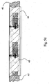
- Fig. 2 which represents the multi-layer arrangement of Fig.
- the base layer 2 provides a first surface 2a, providing the substrate for the working electrodes 8, conductive tracks and contacts 11 of a electrochemical detection means
- the cover layer 4 provides a second surface 4a providing the substrate for corresponding reference electrodes 8', conductive tracks and contacts 11' of a electrochemical detection means.
- the first surface 2a of the base layer 2 is provided with a first hydrophilic pattern 6 forming a first part of a sample distribution system.
- the hydrophilic pattern 6 is surrounded by a hydrophobic insulating layer 14 which serves as hydrophobic "guiding element" for the sample fluid in the sample distribution system and as electrical insulation for the leads, which connect the working electrodes 8 to the electrochemical detection means.
- the second surface 4a of the cover layer 4 is provided with a corresponding hydrophilic pattern 6' forming the second part of a sample distribution system.
- the hydrophilic pattern 6' is, also surrounded by a hydrophobic layer 14', which serves as hydrophobic guiding element for the sample fluid and as electrical insulation for the leads connecting the reference electrodes 8'.
- the hydrophilic patterns 6, 6' forming areas with high surface energy of the sample distribution system comprise a predetermined number of analyte detection areas 6a, 6'a and sample pathways 6b, 6'b (see Fig. 3 ), which are aligned and registered mostly congruent upon assembly of the multi-layer arrangement. Moreover, the working and reference electrodes 8, 8' match with the detection areas 6a, 6'a of the sample distribution system created by the hydrophilic patterns 6, 6' formed on the base and cover layers.
- Base and cover layer are separated by the centre layer 3, which defines the distance between the first surface 2a of the base layer 2 and the second surface 4a of the cover layer 4 and the electrode systems 8 and 8'.
- the centre layer 3 might be constructed from a thin polymer film coated with an adhesive layer on either side but might be realised by a printed layer or other layers respectively spacers, which provide the desired room between the first surface 2a of the base layer 2 and the second surface 4a of the cover layer 4.
- the centre layer provides a precise and exact definition of the distance between base and cover layer.
- the centre layer 3 has a discontinuity 5 to form a hollow cavity together with the first surface 2a of the base layer 2 and the second surface 4a of the cover layer 4.
- the sample distribution system which will be formed by the hydrophilic patterns 6, 6' and the surrounding patterns of the-hydrophobic insulation layers 14, 14' on the first surface 2a respectively the second surface 4a is located within the cavity created by the discontinuity 5 of the centre layer 3 and the first surface 2a of the base layer 2 and the second surface 4a of the cover layer 4.
- the hollow cavity is substantially larger by design than the sample distribution system.
- the applied sample fluid enters the measurement chamber on the hydrophilic pathway (area with high surface energy) of the sample distribution system formed by the hydrophilic patterns 6 and 6' and is constrained by the hydrophobic insulation layers 14 and 14' (areas with low surface energy) within the predetermined flow paths 6b, 6'b and, detection areas 6a, 6'a (see Fig. 3 ) of the sample distribution system between the first surface 2a of the base layer 2 and the second surface 4a of the cover layer 4. Accordingly, the sample will not fill the entire cavity of the analyte test element and allows therefore very small sample volumes of less than 0.5 ⁇ L even with multiple working electrodes.
- the discontinuity 5 of the centre layer 3 can have different forms, such as umbrella shape, rectangular shape or circular shape.
- the discontinuity 5 of the centre layer 3 does not influence the size of the sample distribution system formed on the hydrophilic patterns 6, 6' and therefore does not influence or change the required sample volume.
- the cavity shapes are rather simple, thus allowing the application of simple punch tools and fast processing with less demand on the registration accuracy.
- the centre layer 3 is provided with a first recess 12 to expose the contacts 11 of the working electrodes 8a of the base layer, and a second recess 13, to expose the contacts 11' of the reference electrodes 8'a of the cover layer.
- Fig. 3 shows the construction steps of a preferred embodiment of the analyte test element of the present invention.
- the primary step as shown in row a) is the preparation of the base layer 2 providing a first surface 2a and the cover layer 4 providing a second surface 4a.
- the base layer and cover layer are typically formed from a solid polymer film.
- This process step is followed by the application of the electrodes and the conductive tracks (row b).
- the working electrodes 8 of the electrochemical detection means are applied onto the first surface 2a of the base layer 2 and the corresponding reference electrodes 8' of the electrochemical detection means are applied onto the second surface 4a of the cover layer, but as a matter of course, the working electrodes 8 of the electrochemical detection means can be applied onto the second surface 4a of the cover layer 4 and the corresponding reference electrodes 8' of the electrochemical detection means can be applied onto the first surface 2a of the base layer. Moreover, it is possible to electrically connect all or some of reference electrodes to each other.
- the element is formed from a polyester substrate such as MYLAR ® or MELINEX ® coated with gold or most preferably with palladium.
- the required circuit structure is preferably produced by ablation of the metal layer with a YAG laser. The long wavelength of the laser (1064 nm) primarily evaporates the metal and leaves the polymer film intact, thus the structuring process is very efficient and avoids contamination of the metal layer with burned plastic particles.
- the first surface 2a of the base layer 2 and the second surface 4a, of the cover layer 4 are supplied with equivalent hydrophilic patterns 6, 6' representing the areas of high surface energy, which are wettable by the sample fluid (see row c).
- the hydrophilic patterns 6, 6' are applied in such a manner, that the electrodes 8, 8' match with the detection areas 6a, 6'a of the sample distribution system.
- the preparation of the base and cover layer is concluded by printing a hydrophobic insulation layer 14, 14' (row d), which serves the double purpose of insulating the parts of the conductive circuit, exposing only the electrodes and the contact pads, and restricting the sample fluid to the hydrophilic part of the sample distribution system.
- the hydrophobic inks could be used to decorate the analyte test system with a desired colour, informational text or a product logo. Most preferably, these printing steps are accomplished by flexography. However, other printing or coating processes such as gravure, lithography, offset, inkjet or solid ink printing technology are suitable for the application of the hydrophilic and hydrophobic layers as well. Whereas, the solid ink printing technology is ideally suited for the application of the hydrophobic patterns due to the waxy character of the solid inks itself.
- the flexography allows high-resolution printing on a rotary press and supports highspeed production. It is an established technology for printing on polymer film substrates and widely used in the packaging industry. Low viscous inks are preferred to achieve a thin and even coating of about 2-4 microns. The operation of a four-colour flexography-printing machine is established practice and provides no operational problems. Even though solvent based or UV curing inks are applicable to manufacture analyte test strips, electron beam (EB) curing inks are _ much preferred. These inks provide highest resistance to mechanical and chemical factors, and contain 100% polymers optionally with pigments but no volatile organic solvents and photo initiators, which have proven to affect the stability of sensor chemistry. These positive gains in performance characteristics are derived from the ability of electrons to form crosslinked polymeric films and to penetrate the surface.
- the double bond in the acrylic moiety opens up during interaction with electrons (initiation) and forms a free radical that acts on other monomers forming a chain (propagation) leading to high-molecular-weight polymers.
- initiation electrons
- propagation formation of a chain
- acrylic monomers are available for EB curing that range from simple acrylates such as 2-phenoxyethyl acrylate and isooctyl acrylate to prepolymers like bisphenol A epoxy acrylate and polyester/polyether acrylates ( R. Golden. J. Coatings Technol., 69 (1997), p. 83 ).
- This curing technology allows the design of "functional inks" with the focus on the desired chemical and physical properties without the necessary of solvent and curing systems required by other inks, which may complicate the design process.
- Inks with hydrophilic functions can be realised from a wide selection of cross-linkable water-soluble polymers, e. g. polyalcohols, glycols, polyethylene oxides acrylate derivates, vinylpyrolidone and others.
- Particular interesting are organo-modified-silicone acrylates, which are a cross-linkable species of organo-modified polysiloxanes.
- a typical hydrophobic ink will contain monomers, oligomers, and prepolymers with hydrophobic functions like isooctyl acrylates, dodecyl acrylates, styrene derivates or systems with partly fluorinated carbon chains.
- the catalytic formulations and the calibration formulations of the analyte test element are dosed on the predetermined detection areas (6a and 6'a).
- the detection areas 6a 1 , 6a 2 and 6a 3 of first surface are coated with the catalytic formulations containing an enzyme and a mediator, whereas one detection area (6c) remains uncoated.
- the corresponding detection areas 6'a 1 , 6'a 2 and 6'a 3 are coated with the calibration formulations. Two of the detection areas (e. g.
- 6'a 2 and 6'a 3 are coated with calibration formulations containing different concentrations of the calibration compound, whereas the formulation coated on the third detection area (e. g. 6'a 1 ) contains no calibration compound. Again, detection area (6c) remains uncoated for the background evaluation.
- Fig. 4 is a sectional view of a detection area of the sample distribution system showing a working electrode 8 and a hydrophilic layer 6a of the first part of the sample distribution system applied on the base layer 2 and coated with the enzyme-mediator-layer 18, and a corresponding reference electrode 8' and a hydrophilic layer 6'a forming the second part of the sample distribution system applied on the cover layer 4 and coated with a calibration formulation 19.
- the sample fluid 20 is wetting the areas with high surface energy formed by the hydrophilic layers 6a and 6'a and is constrained in the sample distribution system by the hydrophobic insulating layers 14 and 14'.
- the accuracy of the deposition of the catalytic and calibration formulations is very critical and defines the performance of the analyte test system.
- both formulations are applied with aid of high precision ink-jet systems or piezoelectric print heads.
- the ink is mostly composed from water and the catalytic or calibration compound and will be dried at slightly elevated temperatures.
- Main aspect of these ink formulations is the fast reconstitution of chemical components after sample application without compromising the hydrophobic areas of the analyte test system.
- Suitable catalytic formulations for the present invention are based on a non-reactive base, electron transfer components (mediators), and an enzyme or enzyme combinations as promoter.
- the non-reactive base provides a carrier, which needs to be suitable for ink jet printing, enzyme stabilisation and fixation to the surfaces on the detection areas.
- Non-reactive base Distilled water 65 ml Solvent Citric acid 2.4 g Buffer system Sodium citrate 3 2H 2 O 3.2 g Buffer system Polyethylene glycole 1.0 g Crust inhibitor BSA 3.0 g Enzyme stabilization Gafquat 440 (ISP) 1.0 mL Film forming agent Advantage S (ISP) 1.0 g Film forming agent PVA (low mol.
- Enzyme stabilization Adjust pH to 6.5 and fill up to 100 mL Catalytic formulation: (all components are added to 100 mL non-reactive base) GOD (Aspergillus niger) 2.0 g (250 U/mL) Potassium hexacyanoferrate (III) 2.2 g
- the catalytic formulation depends on the analyte to be detected.
- the formulation can be composed with glucose oxidase (GOD) and potassium hexacyanoferrate (III) as exemplary mediator.
- GOD glucose oxidase
- III potassium hexacyanoferrate
- the selected mediator might be changed for other applications or if the assay is adapted to different enzymes and analytes. Examples for frequently employed mediator systems are: potassium hexacyanoferrate.
- GDH-PQQ glucose dehydrogenase pyrrole-quinoline-quinone
- Suitable inks for the calibration formulation can be composed of the non-reactive base with the required concentration of calibration compound.
- the calibration compound contained in the calibration formulation 19 coated on the predetermined detection areas 6a of second surface 4a is identical or substantially equivalent to the analyte and able to induce the same chemical reaction in the catalytic formulation as the analyte in the physiological fluids sample.
- the calibration compound is preferably glucose as well.
- the article can be assembled in two ways.
- the first one aligns three separate layers: the centre layer goes on the base layer and the application of the cover layer finishes the lamination process. Tight xy registration of base and cover layers becomes a critical task for the function of the analyte test element, if this registration is not achieved, the sample distribution system will not function properly Registration tolerances should be within +/- 5% of the Width of the hydrophilic pathways to achieve good performance.
- the application of the centre layer a double-sided adhesive tape with a preferred thickness of 50 to 80 microns, is less demanding because of the relatively large discontinuity in the material compared to the size of the hydrophilic pathways.
- Electron beam cured inks are most preferred for this alternative centre layer construction due to the minimal shrinkage of the inks during the curing process. Compared to the thickness variation of high quality adhesive tape this alternative printing process might result in a higher variability of the centre layer thickness.
- a first production step of the continuous web production process according to Fig. 5a , patterns of the working and reference electrodes 8, 8' of the electrochemical detection means and hydrophilic patterns 6, 6' of the sample distribution system are printed on one web substrate 44 forming the base and cover layer. As illustrated in Fig. 5a , the printed patterns of the sample distribution systems 6, 6' are arranged on the web substrates 44 opposite to each other and linked in the areas which form later the sample application areas. Thus, the positions of the working and reference electrodes 8, 8' and the predetermined detection areas 6a, 6'a are fixed relative to each other and remain unaffected by the material expansion and web tension.
- first and second surface are provided with the hydrophilic/hydrophobic (6, 14) pattern to create the sample distribution system.
- first or second surface is provided with the hydrophilic/hydrophobic pattern (6, 4), whereas the corresponding surface provides a homogeneous pattern of hydrophilic pixels surrounded by a hydrophobic area thereby creating a surface with semi hydrophilic and semi hydrophobic character (amphiphilic character), and eliminating the necessity to align the hydrophilic and hydrophobic pattern (6, 14) of the first surface with an equivalent hydrophilic and hydrophobic pattern (6', 14') of the second surface.
- amphiphilic surface can be easily designed by the geometric pattern of the hydrophilic pixels and the overall ratio between the hydrophilic and the hydrophobic area.
- amphiphilic character respectively the ratio between hydrophilic pixels and hydrophobic areas, is designed that the sample fluid progresses from hydrophilic pixel to hydrophilic pixel only if the opposite surface provides hydrophilic character. If the opposite surface provides hydrophobic character the movement of the fluid within the capillary gap of the analyte test element will stop.
- This mechanism allows the above-described method to form a functional analyte test element without the stringent requirement of precise registration of the corresponding pattern of the sample distribution system provided on the first and second surface.
- both the first and the second surface are provided with equivalent patterns of high and low surface energy to ensure swift and precise distribution of the sample fluid within the hydrophilic pathways of the sample distribution system.
- the dotted lines 46 indicate the future cutting lines to segregate the analyte test strips, while the dotted lines 45 indicate the future fold line of the web substrate.
- the detection areas 6a, 6'a of the sample distribution system are coated with the catalytic and calibration formulations.
- the detection areas a of the lower row of the web substrate 44 which will represent the first surface of the analyte test element, are coated with the catalytic formulation containing the enzyme and a mediator
- the detection areas 6'a of the upper row of the web substrate 44 which will represent the second surface of the analyte test element, are coated with calibration formulations containing different levels of the calibration compound.
- One of the calibration formulation (e.g. positioned in 6'a 1 ) does not contain calibration compound and delivers the reading of the physiological fluid in the detection step.
- the task to register the centre layer providing the space between base and cover layer becomes less critical due to the large discontinuity 5 furnished in the centre layer, which gives enough tolerance in the production process for a continuous manufacturing schema as shown in Fig. 5b .
- the centre layer 47 is printed it could be applied as last step during the flexographic printing of the analyte test element.
- Various Bonding methods are available to join base and cover layer manufactured with a printed centre layer 47. Most suitable are heat sealing, laser bonding or ultrasound welding.
- an additionally layer 47 which may be formed of double-sided adhesive tape is laminated on one of the surfaces, e. g. the surface 2a of the base layer 2.
- the centre layer 47 which defines the distance between the first and second surface of the base and cover layers, provides breakthroughs 5, 12,'13 exposing the sample distribution system 6 and the contacts of the electrodes 11, 11' and creates a cavity for the sample distribution systems in the analyte test element after the final assembly step.
- FIGS. 5c and 5d Final assembly of the analyte test element is shown in Figures 5c and 5d .
- the analyte test element is assembled by folding the upper half of the web substrate 44 along the fold line 45 on " the lower part of the web substrate, e. g. with help of a folding iron, as illustrated in Fig. 5c creating a sandwich type web as shown in Fig. 5d . Subsequently, a press roller can secure a tight connection between the centre layer, base and cover layers.
- the laminated web is cutted or punched into the desired product shape, whereas line 46 projects an exemplary shape of the final analyte test strip onto the web before the segregation process.
- the top part of the substrate can be folded on to the bottom part without the danger of loosing the registration in the x-direction of the web and provides an easier method to get the right registration of the first and second surfaces forming the sample distribution system in comparison to single sheet process.
- the volume requirement for the sample distribution system contained in the analyte test element of the preferred embodiment is approximately 0.5 ⁇ L-1.0 ⁇ L and requires roughly 100nL - 150nL per detection area. Nevertheless, it will be obvious for the one skilled in the art that the volume of the sample distribution system will vary with various designs and with the number of employed predetermined detection areas as well as with the thickness of the centre layer 3.
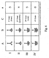
- Fig. 6 shows various patterns of the different sample distribution systems.
- Cell AI in Fig. 6 illustrates the cases for a simple sample distribution system suitable to perform a linear calibration.
- Column A of Fig. 6 shows the principal design of sample distribution systems with no background correction, whereas column B provides designs for sample distribution systems with background corrections.
- Column C indicates the highest order of the polynomial calibration equation achievable with the adjacent designs, and column n indicates the minimum number of predetermined detection areas on each surface, respectively the number of required measurements.
- the literals in each design indicate the position of the background correction (c), sample (1), and all associated calibration areas (2, 3, 4, 5, 6) with increasing amounts or calibration compound.
- the simplest calibration is represented by a linear equation where the relationship between measurement and the analyte concentration is strictly proportional.
- the calibration of the analyte test element is generally performed using the standard addition method by adding a known amount of calibration compound to the sample fluid provided on the different calibration areas and subsequent calculation of a linear or monotone non-lineal calibration equation.
- Fig. 7 gives a more detailed explanation about case I.
- the calibration model or order (column C) needs to be appropriate for the selected analyte and employed detection chemistry, consequently it is not possible to apply a linear calibration model to a chemical reaction which obeys a fourth order model and vice versa.
- the analyte test element designed for five standard additions for a linear calibration the higher amount of standards will allow an even more precise measurement and a statistical validation with higher significance in terms of correlation coefficient, standard deviation and standard error of the test compared to a linear calibration based on two standards.
- a multi analyte system can be realised within the same set of predetermined detection areas if the selected detection chemistries generates no interference problems and the reaction educts and products of one reaction will not take part in the other reaction. Furthermore, it is necessary that the redox-active reaction products can be determined independently at two different electrode potentials. Within this detection schema, the product reacting at a low potential will be determined first before the measurement device is switched to the higher-potential to monitor the second product. Thus, the analysis has to be carried out in a sequential manner, which will require more time compared to the case described above
- the analyte test element is designed to perform n determinations, whereby n is an integer number larger than 2, all of the n detention areas 6a on the first surface 2a are coated with the catalytic formulation (enzyme-mediator-layer 18) promoting the detection of the analyte in the physiologic sample fluid, whereas n predetermined detection areas 6'a on the second surface 4a of calibration compound or analyte and m blank formulations, whereby m is an integer number of at least 1, and n > m.
- n detention areas of the sample distribution system does not contain the calibration compound.
- the physiological fluid After the physiological fluid is applied to the sample application area and distributed to the predetermined detection areas by capillary action, it dissolves the catalytic formulations on the n predetermined detection areas 6a of the first surface 2a as well as the n calibration formulations on the n predetermined detection areas 6'a of the second surface 4a forming a mixture of analyte, calibration compound (which could be identical with the analyte), enzyme and mediator.
- the concentration of the electrochemically, detectable species is changing proportional to the different levels of calibration compound plus the unknown level of analyte, thus allowing the determination of n results by an electrochemical detection means and the calculation of the analyte concentration.
- the catalytic formulation and the calibration formulations applied to the predetermined detection areas are readily soluble by a physiological fluid or other aqueous solutions.
- Both formulations provided on the detection areas opposing each other are positioned in close proximity to facilitate rapid diffusive mixing of the components to allow a fast reaction of all chemical compounds contained in the detection areas and to expedite a fast electrochemical determination of the analyte concentration.
- the processing means calculates the unknown concentration of the analyte from the n measurements performed with the physiological fluid in the analyte test element.
- Fig. 7 shows an exemplary calculation of an analyte concentration in a sample by the linear standard addition method, a known calibration technique used in various fields of analytical chemistry, and now integrated and used in a dry reagent test strip for electrochemical detection for the first time.
- the sample distribution system includes three analyte detection areas, two are coated with different predetermined levels of a calibration compound.
- the catalytic reaction takes place in the analyte detection areas, and the electrochemical detection means measures a first electrochemical signal 21 a, such as the electrical current generated by the sample located in the detection area with the first level of calibration compound.
- the readout of this detection area represents a signal proportional to the combined concentration of the first calibration compound and the concentration of the analyte.
- a second electrochemical signal 21b is produced by the sample located in the detection area with the second level of calibration compound representing a signal proportional to the combined concentration of the second calibration compound and the concentration of the analyte.
- a third electrochemical signal 21c is measured in the detection area containing only the sample with unknown analyte concentration.
- This polynomial equation format provides in conjunction with the n -values presented in Fig. 6 the entity of most useful calibration models for the various designs of the sample distribution systems in the aforementioned figure.
- the values for y and x may represent data calculated by a function to allow pre-processing of raw data generated by the detection mean. Thus, it is possible to use a logarithmic function for linearisation of raw data.
- a preferred embodiment of the analyte test element of the present invention according to Fig. 3 is designed to comprise one detection area, which includes the catalytic compounds but no calibration compound (6a 1 and 6'a 1 , resp.), one detection area which includes the catalytic compounds and a first concentration of the calibration compound (6a 2 and 6'a 2 , resp.), one detection area which includes the catalytic compounds and a second concentration of the calibration compound (6a 3 and 6'a 3 , resp.) and one detection area for the background absorption (6c and 6'c, resp.).
- the latter detection area which includes neither a calibration compound nor catalytic compounds, it is possible to determine the background absorption of the sample and to consider it during the calibration process.
- Fig. 8 illustrates a pre-programmed validation method for calculated results and calibration data, whereby' the validity of the measured results is verified by defining a "validation window" 23b for valid and correct measurements.
- the analyte test system can constrain all data to a validated and useful concentration range, e. g. 30 to 600 mg/dL glucose, and a valid range for the electrochemical signal typically between 0 and 5 ⁇ A depending on the electrode material, mediator, potential and electrode area.
- the processing means can constrain the slope and the intercept or more general the coefficients c 0 to c (a-1) to a valid range, which is particularly useful for non-linear polynomial equations.
- a population of valid measurements with a corresponding calibration line 23a located within the boundaries of the validation window 23b is illustrated in Fig. 8 ; see literals 24a to 24c.
- the quality of the calibration can be judged by a correlation coefficient r 2 and a confidence interval, thus the analyte test system can refuse to display a measurement result if the correlation coefficient falls below a pre-programmed threshold.
- the processing means can calculate a tolerance or concentration range of the result based on the calculated confidence interval.
- Fig. 9 shows the insertion of the analyte test strip into an analyte test system.
- the analyte test strip is designed to have a lateral and concave extension located on one major side of the test strip where the sample application area 9 resides. This feature allows easy application of capillary blood samples from the patients arm or finger as shown in Fig. 10 .
- a plurality of analyte test elements is arranged symmetrically around a centre point to form an analyte test disk 29 with outward facing sample application areas 9.
- the exemplary analyte test disk 29 according to Fig. 11a includes nine analyte test elements 1 of the present invention.
- the analyte test disk 29 is covered by a disk cover or sleeve composed of a top layer 30 and a bottom layer 31.
- the inner side of the top and bottom layer 30, 31 of the sleeve may also be provided with a moisture-absorbing layer 32 to capture the excess of blood after the analyte test element has been used and transported inside the cartridge system.
- the top layer 30 and bottom layer 31 of the disk cover have breakthroughs which are arranged congruently to each other, forming an optical window 25 to expose the active analyte test element and to assist the user to insert the disk into the meter in the right orientation.
- Adjacent to the optical window 25 in the outer peripheral areas of the disk cover top layer 30 and the disk cover bottom layer 31 are two recesses 26 to expose the sample application area 9 of the analyte test elements of the disk.
- the contacts 28a to the working electrode system of the analyte test element and the contacts 28'a (not shown) to the reference electrode system, which are provided on the opposite site from the contacts 28a, are aligned to the interior edge of the disk 29 to expose them to the meter.
- the test disk 29 is additionally provided with a registration notch 33 which may also be located in the interior edge of the disk 29.
- an analyte test disk By means of an analyte test disk, it is possible to arrange a plurality of analyte test elements in a relatively small area. The same number of analyte test elements included in analyte test strips would require a much larger area and thus much more material, as illustrated by the size comparison of analyte test disk and analyte test strips illustrated in Fig. 12 . Whereas the unit area 34 of the analyte test disk 29 includes nine analyte test elements 1, the identical area 35 would accommodate only three analyte test elements incorporated in three analyte test strips 1. However, a reduction of the test strip sizes is not advisable due to the problematical handling of smaller strips which becomes difficult and more impractical for the patient.
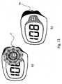
- Fig. 13a and Fig. 13b show the analyte test disk included in a meter, whereby the sample application area 9 again protrudes from the meter housing 36.
- the measurement device analyte test system
- a left hand handling mode is desired according to Fig. 14a
- the analyte test strip 7 is inserted into the meter from the bottom side, the sample application area 9 for receiving the physiological fluid protruding from the meter housing.
- the analyte concentration is presented on the analyte test system display 37.
- a right hand handling mode according to Fig.
- 14b can be realized by adapting the display 37 of the analyte test system to a converse mode of operation by rotating the displayed content on the display by 180°, enabling the insertion of the analyte test strip 7 into the meter from the top side.
- Fig. 15 illustrates another possibility to arrange the analyte test elements in a space-saving manner.
- the analyte test elements are arranged side by side to form a analyte test bandolier 43 with a lateral extension to form the sample application areas 9.
- the area between two analyte test elements is provided with a perforation or break line 42 to separate a single analyte test element 40 from the analyte test bandolier 43.
- analyte test device bandolier stack 41 which can easily housed in a small container to allow an easier dispensing of the single analyte test elements of the analyte test bandolier 43.
- the analyte test element of the present invention produced in disk or strip form, can easily be prepared by processes to those of ordinary skill in the arts of printing, die punching, and laminating.
- the design of the analyte test element allows a simple and cost efficient production process, which is preferably but not necessarily of a continuous nature.
- the analyte test system of the present invention provides reliable results by compensating endogenous interferences, such as different blood types and haematocrit levels, as well as exogenous interferences, such as nutrition supplements like Vitamin C or pharmaceuticals, which otherwise would influence and modify the measuring results.
- endogenous interferences such as different blood types and haematocrit levels
- exogenous interferences such as nutrition supplements like Vitamin C or pharmaceuticals
- the calibration of the analyte test system is done in parallel to the measurements, different environmental parameters; such as temperature at the time of actual measurement, are of no consequence for the accuracy of the determined results.
- production variations e. g. variations in the thickness of the centre layer
- the loss of enzyme activity is detectable due to the internal calibration and can be compensated to a certain extend which leads to a prolonged shelf live of the product. This is especially an advantage in diagnostic systems, which require more sensitive biocatalysts than glucose oxidase.
- the present invention provides an analyte test system that incorporates calibration and quality control means with electrochemical detection means in a dry reagent test element that does not make excessive demand on the production process but eliminates the need for user interventions in calibration and quality control procedures in combination with a tight control of the strip performance at time of sample analysis.
Landscapes
- Health & Medical Sciences (AREA)
- Life Sciences & Earth Sciences (AREA)
- Chemical & Material Sciences (AREA)
- Engineering & Computer Science (AREA)
- Immunology (AREA)
- Physics & Mathematics (AREA)
- Molecular Biology (AREA)
- General Health & Medical Sciences (AREA)
- Organic Chemistry (AREA)
- Analytical Chemistry (AREA)
- Biochemistry (AREA)
- Biophysics (AREA)
- Hematology (AREA)
- Biomedical Technology (AREA)
- Pathology (AREA)
- General Physics & Mathematics (AREA)
- Proteomics, Peptides & Aminoacids (AREA)
- Zoology (AREA)
- Biotechnology (AREA)
- Microbiology (AREA)
- Urology & Nephrology (AREA)
- Wood Science & Technology (AREA)
- Genetics & Genomics (AREA)
- Optics & Photonics (AREA)
- General Engineering & Computer Science (AREA)
- Emergency Medicine (AREA)
- Chemical Kinetics & Catalysis (AREA)
- Cell Biology (AREA)
- Electrochemistry (AREA)
- Food Science & Technology (AREA)
- Medicinal Chemistry (AREA)
- Bioinformatics & Cheminformatics (AREA)
- Heart & Thoracic Surgery (AREA)
- Medical Informatics (AREA)
- Surgery (AREA)
- Animal Behavior & Ethology (AREA)
- Public Health (AREA)
- Veterinary Medicine (AREA)
- Investigating Or Analysing Biological Materials (AREA)
- Measurement Of The Respiration, Hearing Ability, Form, And Blood Characteristics Of Living Organisms (AREA)
Abstract
Description
- This invention relates to the field of quantitative analysis of an analyte, e. g. glucose, in a physiological fluid, e. g. blood. More particularly, this invention provides an analyte test system and test method for the quantitative determination of analytes in a physiological or aqueous fluid and a method of preparation.
- The determination of analyte concentrations in physiological samples plays a prominent role in diagnosis and therapy of a variety of diseases. Analyzes of interest include among others glucose, cholesterol free fatty acids, triglycerides, proteins, ketones, phenylalanine, enzymes, antibodies, or peptides in blood, plasma, urine or saliva.
- Measuring the glucose concentration in samples of whole blood is a particularly common task. Since Diabetes causes dangerous physiological complications leading to the loss of vision, kidney failure and other serious medical consequences. Only a stringent therapy and disease management minimises the risk of these consequences with adjustments on exercise, diet, and medication. Some patients have to test their blood glucose concentration frequently with three or more measurements a day. These patients as well as clinicians and hospitals require an accurate, reliable, and ideally inexpensive method to adjust their treatment regimes to avoid the long-term complications of diabetes mellitus.
- The increased awareness about diabetes, the acceptance of self-monitoring and self-treatment have been dependent upon the availability of suitable devices and let to the development of a multitude of devices and methods for personal use and point of care testing as well. Available are pregnancy, ovulations, blood coagulation, ketone and cholesterol tests, as example for a non-exhaustive selection, but most prominent in the area of self-monitoring is still the detection of glucose in capillary blood.
- Typically, a physiological sample fluid, e. g. capillary blood, is applied to a test strip to evaluate the concentration of an analyte. The test strips are usually used in conjunction with a measuring device which measures light reflectance and/or transmittance, if the strip is designed for photometric detection, or some electrical properties, such as electrical current, if the strip is designed for detection of an electro-active compound.
- European Patent Application Publication No.
EP 0 215 419 A2 , for example, describes a device and a method for uniform distribution of a defined volume of a liquid test specimen onto a reactive surface via a capillary gap to provide a controlled and predetermined flow pattern for the specimen liquid. United States Patent No.4,687,529 , on the other hand, controls the liquid present in a reagent matrix material using hydrophobic barrier pads on a reagent test device, which prevents or minimises cross-contamination of reagents on the test device substrate. - Over the last couple of years electrochemical biosensors became more and more prominent on the diagnostic market and provide the patient with several advantages over the reflectance photometry systems. Main differences are the capillary fill features of the test strips allowing an easier sample application in comparison of the top fill membrane based reflectance photometry systems. Additionally, the measurement cell can be located at the tip of the strip thus the blood sample will not be in direct contact with the measurement device (meter) during the test procedure, which keeps the device clean and hygienic avoiding blood contamination of the meter.
- Until today a wide variety of electrochemical biosensor strips has evolved. An exemplary electrochemical biosensor as disclosed in
US Patent 5,288,636 , includes a working and a counter/reference electrode. A reagent, which includes an enzyme capable of catalyzing a reaction involving a substrate for the enzyme, a redox mediator capable of transferring electrons transferred between the enzyme and the working electrode, and a buffer, is located at the working electrode surface. When a sample fluid containing the analyte to be measured is added to the reagent, a reaction occurs that oxidizes the analyte and reduces the redox mediator. After or during this reaction, an electric potential difference is applied between the electrodes. The current produced by the electrooxidation of the reduced form of the mediator is measured and correlated to the amount of the analyte in the sample. - In a typical embodiment, the electrochemical system consists of two electrodes on a support member enclosed by supporting walls to form a cavity which is either small enough to be filled by capillary action (
US 4,900,424 ; Birth et al., 1987), or with help of a spreading or mesh layers.(US 5,628,890 ; Carter metal, 1997). - Due to the raw material and process variations in large-scale manufacture of the analyte strips an adequate strip-to-strip reproducibility from one batch to the next is not guaranteed. Therefore, all known systems require test strips, which have to be calibrated during the production process. This calibration information is provided by the time of use to the meter by manual or automatic means. In the first case the user has to enter the calibration information in form of a number with comes with each lot of test strips, in the second case the information, is encoded in the strip either by bar, colour, or a digital coding feature. Therefore this type of calibration information represents the functional characteristic of the test strip by the time of production, which may or may not be different for the test strip characteristics by the time of use that could be up to two years later.
- Furthermore, the measuring procedure may be impaired by other variable factors in the physiological sample fluid. A typical complication in whole blood analysis is the variability of erythrocyte levels, leading to results which may not reflect the real analyte concentration of the sample.
-
PCT/EP 2004002284 - However, up to now no analyte test system exists, which is suitable for electrochemical detection and quantitative determination of an analyte in a physiological fluid and which is provided with integrated calibration and quality control means.
- Therefore, it is the object of the present invention, to provide an analyte test system with an integrated calibration means, which accounts for and compensates any variability may it be generated by fluctuations in the production process or by the variability of the analysed sample itself, which has electrochemical detection means for measuring the concentration of an analyte in a physiological fluid sample.
- It is a further object of the present invention, to provide a production process for the electrochemical analyte test element which does not involve many and complicated production steps and therefore is inexpensive and usable for products assisting patients in self-monitoring blood glucose or other important physiological parameters.
- This invention provides an element for determining the concentration of an analyte like glucose, cholesterol, free fatty acids, triglycerides, proteins, ketones, phenylalanine or enzymes, in a physiological fluid like blood, serum, plasma, saliva, urine, interstitial and/or intracellular fluid, the device incorporating calibration and quality, control means with electrochemical detection means in a dry reagent test strip. The production of the inventive analyte test element involves only a small number of uncomplicated production steps enabling an inexpensive production of the strips.
- Due to the integrated calibration procedure the analyte test system of the present invention provides reliable results regardless of the blood type, haematocrit level, temperature etc.. In addition, production variations are compensated by the integrated calibration procedure as well. Moreover, active component aging is detectable and can be compensated and/or reported which will lead to a prolonged shelf live of the product under suitable storage conditions.
- The present invention provides an analyte test element for determining the concentration of at least one analyte in a physiological sample fluid having a first and a second surface in a " predetermined distance opposite from each other, said both surfaces are provided with two substantially equivalent patterns forming areas of high and low surface energy which are aligned mostly congruent, whereby the areas with high surface energy create a sample distribution system with at least two detection areas, characterized in that the detection areas of first and second surface are also provided with two corresponding patterns of working and reference electrodes of electrochemical detection means.
- The sample distribution system contained in the inner part of the analyte test element has no mechanical and/or structural features resembling walls, groves, or channels to guide the physiological fluid to the detection areas which leads to an easy, cost efficient and reliable production process.
- In another aspect, the invention provides a method for preparing the analyte test element of the present invention with the steps:
- applying a pattern of working electrodes on a first layer having a first surface,
- applying a corresponding pattern of reference electrodes on a second layer having a second surface,
- generating areas of high and low surface energy on the first-layer having the first surface,
- generating a corresponding pattern of areas of high and low surface energy on the second layer having the second surface, the areas of high surface energy forming a hydrophilic sample distribution system with n predetermined detection areas, whereby n is an integer number larger than 2, whereby the working and reference electrodes are located underneath the n predetermined detection areas of the hydrophilic sample distribution system,
- coating a catalytic formulation on the n detection areas of the first surface, said catalytic formulation promoting the detection of an analyte concentration contained in physiological fluid sample using electrochemical detection means,
- coating n calibration formulations on n detection areas of the second surface, said n calibration formulations made up of m blank formulations and n-m formulations with different levels of calibration compound, whereby m is an integer number of at least 1, and n>m, which, is identical or substantially equivalent to the analyte and able to induce the same chemical reaction in the catalytic formulation as the analyte in the physiological fluid sample,
- applying the layers of first and second surfaces to the opposite sites of a centre layer having a discontinuity which provides a cavity for the sample distribution system formed by the areas of high surface energy on the first and second surfaces of the base and cover layer.
- The analyte test element is described in several embodiments suitable for a variety of calibration procedures and adaptable to different analytes and electrochemical determination methods; it is easily integrated in test strips used for a single measurement or in more complex arrangements such as analyte test disks or bandoliers to provide base units for several measurements.
- Other features and advantages of the present invention and the preferred embodiment thereof will become apparent from the following description in conjunction with the attached drawings.
-
-
Fig.1 is a perspective view of one embodiment of the analyte test element of the present invention provided in shape of a test strip. -
Fig. 2 is an exploded perspective view of the element according toFig. 1 showing the different layers separately. -
Fig. 3 shows the sequential coating of the different layers onto the base and cover layers. -
Fig. 4 is a sectional view of a detection area of the sample distribution system of the analyte test element. -
Fig. 5a to 5d show the steps of a continuous-web production process of analyte test elements with strip shape. -
Fig.6 shows different embodiments of the sample distribution system with different patterns of pathways and detection areas suitable for different calibration methods. -
Fig. 7 is a graph showing the calculation of the sample analyte concentration using the standard addition method. -
Fig. 8 is a graph showing the validation method for the calculated results and calibration data. -
Fig. 9 shows an exemplary application of an inventive test strip with a meter. -
Fig. 10 shows the analyte test system with an inserted analyte test strip ready to receive a sample of capillary blood from the finger tip of a patient. -
Fig. 11 shows the construction of an analyte test disk. -
Fig. 12 shows an analyte test disk compared to an analyte test strip. -
Fig. 13 shows a analyte test system with an integrated analyte test disk. -
Fig. 14 shows a analyte test system with an analyte test strip in left hand and right hand handling mode. -
Fig. 15 shows an analyte test bandolier and folded bandolier to build a stack. - The layers shown in
Fig. 4 are not to scale, in particular the thickness of thelayers -
Fig. 1 shows the analyte test element of the present invention in shape of atest strip 1 comprising abase layer 2, acentre layer 3 overlaying thebase layer 2, and acover layer 4 overlaying thecentre layer 3. Thecentre layer 3 presents a discontinuity 5 (seeFig. 2 ), which creates a hollow cavity in conjunction with thebase layer 2 and thecover layer 4. Within said cavity there is located asample distribution system 6 which is connected to asample application area 9 located on one side of the analyte test strip. Thesample application area 9 as interface to the user is preferably formed by aconvex extrusion 10 extending from one major side of the analyte test strip to allow easy application of the sample. Opposite to thesample application area 9 on the second major side of the analyte test strip is the location of an air vent (not shown) allowing the displacement of air while the physiological fluid is distributed to the sample distribution system. - In addition, the
analyte test strip 1 possesses registration features 7 useful to differentiate between several kinds of analyte test strips e. g. for the determination of different analytes. By this means, a multi-analyte meter could be instructed to run a special program or procedures with selectable parameters upon strip insertion required for the determination of a particular analyte. As illustrated inFig. 2 , which represents the multi-layer arrangement ofFig. 1 in an exploded view, thebase layer 2 provides afirst surface 2a, providing the substrate for the workingelectrodes 8, conductive tracks andcontacts 11 of a electrochemical detection means, and thecover layer 4 provides asecond surface 4a providing the substrate for corresponding reference electrodes 8', conductive tracks and contacts 11' of a electrochemical detection means. - Additionally, the
first surface 2a of thebase layer 2 is provided with a firsthydrophilic pattern 6 forming a first part of a sample distribution system. Thehydrophilic pattern 6 is surrounded by a hydrophobic insulatinglayer 14 which serves as hydrophobic "guiding element" for the sample fluid in the sample distribution system and as electrical insulation for the leads, which connect the workingelectrodes 8 to the electrochemical detection means. Also, thesecond surface 4a of thecover layer 4 is provided with a corresponding hydrophilic pattern 6' forming the second part of a sample distribution system. The hydrophilic pattern 6' is, also surrounded by a hydrophobic layer 14', which serves as hydrophobic guiding element for the sample fluid and as electrical insulation for the leads connecting the reference electrodes 8'. - The
hydrophilic patterns 6, 6' forming areas with high surface energy of the sample distribution system comprise a predetermined number ofanalyte detection areas 6a, 6'a andsample pathways 6b, 6'b (seeFig. 3 ), which are aligned and registered mostly congruent upon assembly of the multi-layer arrangement. Moreover, the working andreference electrodes 8, 8' match with thedetection areas 6a, 6'a of the sample distribution system created by thehydrophilic patterns 6, 6' formed on the base and cover layers. - Base and cover layer are separated by the
centre layer 3, which defines the distance between thefirst surface 2a of thebase layer 2 and thesecond surface 4a of thecover layer 4 and theelectrode systems 8 and 8'. Thecentre layer 3 might be constructed from a thin polymer film coated with an adhesive layer on either side but might be realised by a printed layer or other layers respectively spacers, which provide the desired room between thefirst surface 2a of thebase layer 2 and thesecond surface 4a of thecover layer 4. For the functionality of the analyte test element it is only important that the centre layer provides a precise and exact definition of the distance between base and cover layer. - The
centre layer 3 has adiscontinuity 5 to form a hollow cavity together with thefirst surface 2a of thebase layer 2 and thesecond surface 4a of thecover layer 4. The sample distribution system which will be formed by thehydrophilic patterns 6, 6' and the surrounding patterns of the-hydrophobic insulation layers 14, 14' on thefirst surface 2a respectively thesecond surface 4a is located within the cavity created by thediscontinuity 5 of thecentre layer 3 and thefirst surface 2a of thebase layer 2 and thesecond surface 4a of thecover layer 4. Preferably, the hollow cavity is substantially larger by design than the sample distribution system. Within a functional analyte test element the applied sample fluid enters the measurement chamber on the hydrophilic pathway (area with high surface energy) of the sample distribution system formed by thehydrophilic patterns 6 and 6' and is constrained by the hydrophobic insulation layers 14 and 14' (areas with low surface energy) within thepredetermined flow paths 6b, 6'b and,detection areas 6a, 6'a (seeFig. 3 ) of the sample distribution system between thefirst surface 2a of thebase layer 2 and thesecond surface 4a of thecover layer 4. Accordingly, the sample will not fill the entire cavity of the analyte test element and allows therefore very small sample volumes of less than 0.5 µL even with multiple working electrodes. - Since the purpose of the
discontinuity 5 of the centre layer is only to create a cavity for the sample distribution system formed by thehydrophilic patterns 6, 6', thediscontinuity 5 of thecentre layer 3 can have different forms, such as umbrella shape, rectangular shape or circular shape. Thediscontinuity 5 of thecentre layer 3 does not influence the size of the sample distribution system formed on thehydrophilic patterns 6, 6' and therefore does not influence or change the required sample volume. Compared to the sampledistribution system patterns 6, 6', the cavity shapes are rather simple, thus allowing the application of simple punch tools and fast processing with less demand on the registration accuracy. - Additionally, the
centre layer 3 is provided with afirst recess 12 to expose thecontacts 11 of the working electrodes 8a of the base layer, and asecond recess 13, to expose the contacts 11' of the reference electrodes 8'a of the cover layer. -
Fig. 3 shows the construction steps of a preferred embodiment of the analyte test element of the present invention. The primary step as shown in row a) is the preparation of thebase layer 2 providing afirst surface 2a and thecover layer 4 providing asecond surface 4a. The base layer and cover layer are typically formed from a solid polymer film. Within certain embodiments it is advantageous to select transparent polymer films as substrate to allow the patient to monitor the filling of the analyte test element of the analyte test strip, however it is not required for the proper function of the analyte test system. - This process step is followed by the application of the electrodes and the conductive tracks (row b). In the embodiment of the present invention according to
Fig. 3 , the workingelectrodes 8 of the electrochemical detection means are applied onto thefirst surface 2a of thebase layer 2 and the corresponding reference electrodes 8' of the electrochemical detection means are applied onto thesecond surface 4a of the cover layer, but as a matter of course, the workingelectrodes 8 of the electrochemical detection means can be applied onto thesecond surface 4a of thecover layer 4 and the corresponding reference electrodes 8' of the electrochemical detection means can be applied onto thefirst surface 2a of the base layer. Moreover, it is possible to electrically connect all or some of reference electrodes to each other. - Several technologies are known in the art and used in the industry to produce conductive patterns of tracks and electrodes, which can be adopted for this step. Suitable are screen printing of carbon or noble metal inks, physical or chemical vapour deposition of noble metals or carbon with subsequent laser or photolithographic patterning of the required circuit structure, or chemical deposition of noble metals on compatible surfaces. Clean noble metal structures such as gold, palladium, and platinum produced in a vapour deposition process are most suitable for a reliable and reproducible electrochemical measurement. In a preferred embodiment, the element is formed from a polyester substrate such as MYLAR® or MELINEX® coated with gold or most preferably with palladium. The required circuit structure is preferably produced by ablation of the metal layer with a YAG laser. The long wavelength of the laser (1064 nm) primarily evaporates the metal and leaves the polymer film intact, thus the structuring process is very efficient and avoids contamination of the metal layer with burned plastic particles.
- After completion of the circuit structure the
first surface 2a of thebase layer 2 and thesecond surface 4a, of thecover layer 4 are supplied with equivalenthydrophilic patterns 6, 6' representing the areas of high surface energy, which are wettable by the sample fluid (see row c). Thehydrophilic patterns 6, 6' are applied in such a manner, that theelectrodes 8, 8' match with thedetection areas 6a, 6'a of the sample distribution system. The preparation of the base and cover layer is concluded by printing ahydrophobic insulation layer 14, 14' (row d), which serves the double purpose of insulating the parts of the conductive circuit, exposing only the electrodes and the contact pads, and restricting the sample fluid to the hydrophilic part of the sample distribution system. Additionally, the hydrophobic inks could be used to decorate the analyte test system with a desired colour, informational text or a product logo. Most preferably, these printing steps are accomplished by flexography. However, other printing or coating processes such as gravure, lithography, offset, inkjet or solid ink printing technology are suitable for the application of the hydrophilic and hydrophobic layers as well. Whereas, the solid ink printing technology is ideally suited for the application of the hydrophobic patterns due to the waxy character of the solid inks itself. - The flexography allows high-resolution printing on a rotary press and supports highspeed production. It is an established technology for printing on polymer film substrates and widely used in the packaging industry. Low viscous inks are preferred to achieve a thin and even coating of about 2-4 microns. The operation of a four-colour flexography-printing machine is established practice and provides no operational problems. Even though solvent based or UV curing inks are applicable to manufacture analyte test strips, electron beam (EB) curing inks are _ much preferred. These inks provide highest resistance to mechanical and chemical factors, and contain 100% polymers optionally with pigments but no volatile organic solvents and photo initiators, which have proven to affect the stability of sensor chemistry. These positive gains in performance characteristics are derived from the ability of electrons to form crosslinked polymeric films and to penetrate the surface.
- Inks used in EB curing make use of the polymerizing capability of acrylic monomers and oligomers. Acrylic chemistry has a special significance in modem day inks. (6J.T. Kunjappu. "The Emergence of Polyacrylates in Ink Chemistry," Ink World, February, 1999, p. 40.) The structure of the simplest acrylic compound, acrylic acid, is shown in the equation below.
CH2=CH-COOH
- The double bond in the acrylic moiety opens up during interaction with electrons (initiation) and forms a free radical that acts on other monomers forming a chain (propagation) leading to high-molecular-weight polymers. As mentioned above, radiation induced polymerisation requires no external initiator since radiation itself generates free radicals with the result that no initiating species will be left in the coating.
- A variety of acrylic monomers are available for EB curing that range from simple acrylates such as 2-phenoxyethyl acrylate and isooctyl acrylate to prepolymers like bisphenol A epoxy acrylate and polyester/polyether acrylates (R. Golden. J. Coatings Technol., 69 (1997), p. 83). This curing technology allows the design of "functional inks" with the focus on the desired chemical and physical properties without the necessary of solvent and curing systems required by other inks, which may complicate the design process.
- Inks with hydrophilic functions can be realised from a wide selection of cross-linkable water-soluble polymers, e. g. polyalcohols, glycols, polyethylene oxides acrylate derivates, vinylpyrolidone and others. Particular interesting are organo-modified-silicone acrylates, which are a cross-linkable species of organo-modified polysiloxanes. A typical hydrophobic ink will contain monomers, oligomers, and prepolymers with hydrophobic functions like isooctyl acrylates, dodecyl acrylates, styrene derivates or systems with partly fluorinated carbon chains.
- After completion of the base and cover layer with all the required conductive, hydrophilic and hydrophobic coatings, the catalytic formulations and the calibration formulations of the analyte test element are dosed on the predetermined detection areas (6a and 6'a). In the embodiment of the test element according to
Fig. 3 , thedetection areas -
Fig. 4 is a sectional view of a detection area of the sample distribution system showing a workingelectrode 8 and ahydrophilic layer 6a of the first part of the sample distribution system applied on thebase layer 2 and coated with the enzyme-mediator-layer 18, and a corresponding reference electrode 8' and a hydrophilic layer 6'a forming the second part of the sample distribution system applied on thecover layer 4 and coated with acalibration formulation 19. Thesample fluid 20 is wetting the areas with high surface energy formed by thehydrophilic layers 6a and 6'a and is constrained in the sample distribution system by the hydrophobic insulatinglayers 14 and 14'. - The accuracy of the deposition of the catalytic and calibration formulations is very critical and defines the performance of the analyte test system. Preferably, both formulations are applied with aid of high precision ink-jet systems or piezoelectric print heads. The ink is mostly composed from water and the catalytic or calibration compound and will be dried at slightly elevated temperatures. Main aspect of these ink formulations is the fast reconstitution of chemical components after sample application without compromising the hydrophobic areas of the analyte test system.
- Suitable catalytic formulations for the present invention are based on a non-reactive base, electron transfer components (mediators), and an enzyme or enzyme combinations as promoter. The non-reactive base provides a carrier, which needs to be suitable for ink jet printing, enzyme stabilisation and fixation to the surfaces on the detection areas. An exemplary composition for 100 mL formulation is given below
Non-reactive base: Distilled water 65 ml Solvent Citric acid 2.4 g Buffer system Sodium citrate 3 2H2O 3.2 g Buffer system Polyethylene glycole 1.0 g Crust inhibitor BSA 3.0 g Enzyme stabilization Gafquat 440 (ISP) 1.0 mL Film forming agent Advantage S (ISP) 1.0 g Film forming agent PVA (low mol. weight) 1.5 g Enzyme stabilization Adjust pH to 6.5 and fill up to 100 mL Catalytic formulation: (all components are added to 100 mL non-reactive base) GOD (Aspergillus niger) 2.0 g (250 U/mL) Potassium hexacyanoferrate (III) 2.2 g - The catalytic formulation depends on the analyte to be detected. In case of glucose determination, the formulation can be composed with glucose oxidase (GOD) and potassium hexacyanoferrate (III) as exemplary mediator. The selected mediator might be changed for other applications or if the assay is adapted to different enzymes and analytes. Examples for frequently employed mediator systems are: potassium hexacyanoferrate. (III), tetracyano-p-quinone-di-methane (TCNQ), methylviologen (MV2+), tetrathiafulavene (TTF), N-methylphenzinium (NMP+), 1,1'-dimethylferrocen, ruthenium (III) hexamine, osmium bipyridine, ferrocene and their derivates.
- Different enzymes and mediators might require the adjustment of the pH of the non-reactive base as well. Alternatively, potassium hexacyanoferrate (III) could be used with glucose dehydrogenase pyrrole-quinoline-quinone (GDH-PQQ) instead of GOD. Sensors with GDH (glucose dehydrogenase) enzyme show similar performance as sensors with GOD enzyme with reduced oxygen sensitivity but with a higher cross-reactivity to galactose and maltose.
- Suitable inks for the calibration formulation can be composed of the non-reactive base with the required concentration of calibration compound. Preferably, the calibration compound contained in the
calibration formulation 19 coated on thepredetermined detection areas 6a ofsecond surface 4a is identical or substantially equivalent to the analyte and able to induce the same chemical reaction in the catalytic formulation as the analyte in the physiological fluids sample. In case the analyte of interest in the physiological sample is glucose then the calibration compound is preferably glucose as well. - After completion of all printing and coating steps the article can be assembled in two ways. The first one aligns three separate layers: the centre layer goes on the base layer and the application of the cover layer finishes the lamination process. Tight xy registration of base and cover layers becomes a critical task for the function of the analyte test element, if this registration is not achieved, the sample distribution system will not function properly Registration tolerances should be within +/- 5% of the Width of the hydrophilic pathways to achieve good performance. The application of the centre layer, a double-sided adhesive tape with a preferred thickness of 50 to 80 microns, is less demanding because of the relatively large discontinuity in the material compared to the size of the hydrophilic pathways.
- Alternatively, a special printing process could be used to apply 50 to 80 microns of ink paste to realize the centre layer. Electron beam cured inks are most preferred for this alternative centre layer construction due to the minimal shrinkage of the inks during the curing process. Compared to the thickness variation of high quality adhesive tape this alternative printing process might result in a higher variability of the centre layer thickness.
- Registration is especially demanding in continuous production lines where the substrate progresses with several meters up to tens of meters per minute. Substrate expansion and web tension make the registration in x-direcdon (the direction of the web) more difficult than the y-direction perpendicular to the web movement.
Figure 5 illustrates a solution for this problem; here cover and base layer are printed on one substrate. Thus the position of the predetermined detection areas and flow paths of the sample distribution system are fixed relative to each other and remains unaffected by the material expansion and web tension. - In a first production step of the continuous web production process according to
Fig. 5a , patterns of the working andreference electrodes 8, 8' of the electrochemical detection means andhydrophilic patterns 6, 6' of the sample distribution system are printed on oneweb substrate 44 forming the base and cover layer. As illustrated inFig. 5a , the printed patterns of thesample distribution systems 6, 6' are arranged on theweb substrates 44 opposite to each other and linked in the areas which form later the sample application areas. Thus, the positions of the working andreference electrodes 8, 8' and thepredetermined detection areas 6a, 6'a are fixed relative to each other and remain unaffected by the material expansion and web tension. - In an alternative embodiment only one of the first and second surface is provided with the hydrophilic/hydrophobic (6, 14) pattern to create the sample distribution system. In a preferred embodiment, either the first or second surface is provided with the hydrophilic/hydrophobic pattern (6, 4), whereas the corresponding surface provides a homogeneous pattern of hydrophilic pixels surrounded by a hydrophobic area thereby creating a surface with semi hydrophilic and semi hydrophobic character (amphiphilic character), and eliminating the necessity to align the hydrophilic and hydrophobic pattern (6, 14) of the first surface with an equivalent hydrophilic and hydrophobic pattern (6', 14') of the second surface. The properties of such an amphiphilic surface can be easily designed by the geometric pattern of the hydrophilic pixels and the overall ratio between the hydrophilic and the hydrophobic area. In the disclosed invention the amphiphilic character, respectively the ratio between hydrophilic pixels and hydrophobic areas, is designed that the sample fluid progresses from hydrophilic pixel to hydrophilic pixel only if the opposite surface provides hydrophilic character. If the opposite surface provides hydrophobic character the movement of the fluid within the capillary gap of the analyte test element will stop. This mechanism allows the above-described method to form a functional analyte test element without the stringent requirement of precise registration of the corresponding pattern of the sample distribution system provided on the first and second surface. However, most preferably both the first and the second surface are provided with equivalent patterns of high and low surface energy to ensure swift and precise distribution of the sample fluid within the hydrophilic pathways of the sample distribution system.
- The dotted
lines 46 indicate the future cutting lines to segregate the analyte test strips, while the dottedlines 45 indicate the future fold line of the web substrate. - After printing the patterns of working and reference electrodes, the hydrophilic patterns of the sample distribution system and the hydrophobic insulating layer, the
detection areas 6a, 6'a of the sample distribution system are coated with the catalytic and calibration formulations. For example, the detection areas a of the lower row of theweb substrate 44, which will represent the first surface of the analyte test element, are coated with the catalytic formulation containing the enzyme and a mediator, whereas the detection areas 6'a of the upper row of theweb substrate 44, which will represent the second surface of the analyte test element, are coated with calibration formulations containing different levels of the calibration compound. One of the calibration formulation (e.g. positioned in 6'a1) does not contain calibration compound and delivers the reading of the physiological fluid in the detection step. - The task to register the centre layer providing the space between base and cover layer becomes less critical due to the
large discontinuity 5 furnished in the centre layer, which gives enough tolerance in the production process for a continuous manufacturing schema as shown inFig. 5b . In case thecentre layer 47 is printed it could be applied as last step during the flexographic printing of the analyte test element. Various Bonding methods are available to join base and cover layer manufactured with a printedcentre layer 47. Most suitable are heat sealing, laser bonding or ultrasound welding. Alternatively, an additionallylayer 47 which may be formed of double-sided adhesive tape is laminated on one of the surfaces, e. g. thesurface 2a of thebase layer 2. - The
centre layer 47 which defines the distance between the first and second surface of the base and cover layers, providesbreakthroughs sample distribution system 6 and the contacts of theelectrodes 11, 11' and creates a cavity for the sample distribution systems in the analyte test element after the final assembly step. - Final assembly of the analyte test element is shown in
Figures 5c and5d . The analyte test element is assembled by folding the upper half of theweb substrate 44 along thefold line 45 on " the lower part of the web substrate, e. g. with help of a folding iron, as illustrated inFig. 5c creating a sandwich type web as shown inFig. 5d . Subsequently, a press roller can secure a tight connection between the centre layer, base and cover layers. - Finally, the laminated web is cutted or punched into the desired product shape, whereas
line 46 projects an exemplary shape of the final analyte test strip onto the web before the segregation process. With the preparation method illustrated inFig. 5 the top part of the substrate can be folded on to the bottom part without the danger of loosing the registration in the x-direction of the web and provides an easier method to get the right registration of the first and second surfaces forming the sample distribution system in comparison to single sheet process. - The volume requirement for the sample distribution system contained in the analyte test element of the preferred embodiment is approximately 0.5µL-1.0µL and requires roughly 100nL - 150nL per detection area. Nevertheless, it will be obvious for the one skilled in the art that the volume of the sample distribution system will vary with various designs and with the number of employed predetermined detection areas as well as with the thickness of the
centre layer 3. -
Fig. 6 shows various patterns of the different sample distribution systems. Cell AI inFig. 6 illustrates the cases for a simple sample distribution system suitable to perform a linear calibration. Column A ofFig. 6 shows the principal design of sample distribution systems with no background correction, whereas column B provides designs for sample distribution systems with background corrections. Column C indicates the highest order of the polynomial calibration equation achievable with the adjacent designs, and column n indicates the minimum number of predetermined detection areas on each surface, respectively the number of required measurements. The literals in each design indicate the position of the background correction (c), sample (1), and all associated calibration areas (2, 3, 4, 5, 6) with increasing amounts or calibration compound. The simplest calibration is represented by a linear equation where the relationship between measurement and the analyte concentration is strictly proportional. The calibration of the analyte test element is generally performed using the standard addition method by adding a known amount of calibration compound to the sample fluid provided on the different calibration areas and subsequent calculation of a linear or monotone non-lineal calibration equation. -
Fig. 7 gives a more detailed explanation about case I. The calibration model or order (column C) needs to be appropriate for the selected analyte and employed detection chemistry, consequently it is not possible to apply a linear calibration model to a chemical reaction which obeys a fourth order model and vice versa. However, it is still possible to use the analyte test element designed for five standard additions for a linear calibration, the higher amount of standards will allow an even more precise measurement and a statistical validation with higher significance in terms of correlation coefficient, standard deviation and standard error of the test compared to a linear calibration based on two standards. - Moreover, the repetition of sample and standard measurements is possible as well, thus it is possible to perform two independent linear calibrations for one particular sample of physiological fluid with the embodiments shown in row IV. Likewise, it is possible to use the same analyte test element for the determination of two analytes.
- Alternatively, a multi analyte system can be realised within the same set of predetermined detection areas if the selected detection chemistries generates no interference problems and the reaction educts and products of one reaction will not take part in the other reaction. Furthermore, it is necessary that the redox-active reaction products can be determined independently at two different electrode potentials. Within this detection schema, the product reacting at a low potential will be determined first before the measurement device is switched to the higher-potential to monitor the second product. Thus, the analysis has to be carried out in a sequential manner, which will require more time compared to the case described above
- If the analyte test element is designed to perform n determinations, whereby n is an integer number larger than 2, all of the
n detention areas 6a on thefirst surface 2a are coated with the catalytic formulation (enzyme-mediator-layer 18) promoting the detection of the analyte in the physiologic sample fluid, whereas n predetermined detection areas 6'a on thesecond surface 4a of calibration compound or analyte and m blank formulations, whereby m is an integer number of at least 1, and n>m. In other words, at least one of the n defection areas of the sample distribution system does not contain the calibration compound. - After the physiological fluid is applied to the sample application area and distributed to the predetermined detection areas by capillary action, it dissolves the catalytic formulations on the n predetermined
detection areas 6a of thefirst surface 2a as well as the n calibration formulations on the n predetermined detection areas 6'a of thesecond surface 4a forming a mixture of analyte, calibration compound (which could be identical with the analyte), enzyme and mediator. Within these n mixtures the concentration of the electrochemically, detectable species is changing proportional to the different levels of calibration compound plus the unknown level of analyte, thus allowing the determination of n results by an electrochemical detection means and the calculation of the analyte concentration. Preferably, the catalytic formulation and the calibration formulations applied to the predetermined detection areas are readily soluble by a physiological fluid or other aqueous solutions. Both formulations provided on the detection areas opposing each other are positioned in close proximity to facilitate rapid diffusive mixing of the components to allow a fast reaction of all chemical compounds contained in the detection areas and to expedite a fast electrochemical determination of the analyte concentration. - Since there are more than two detection areas arranged within the sample distribution system, whereby at least two of the detection areas contain known but different levels of calibration compound, it is possible for the processing means to calculate the unknown concentration of the analyte from the n measurements performed with the physiological fluid in the analyte test element.
-
Fig. 7 shows an exemplary calculation of an analyte concentration in a sample by the linear standard addition method, a known calibration technique used in various fields of analytical chemistry, and now integrated and used in a dry reagent test strip for electrochemical detection for the first time. In this example, the sample distribution system includes three analyte detection areas, two are coated with different predetermined levels of a calibration compound. After applying the physiological fluid to the sample distribution system, the catalytic reaction takes place in the analyte detection areas, and the electrochemical detection means measures a firstelectrochemical signal 21 a, such as the electrical current generated by the sample located in the detection area with the first level of calibration compound. The readout of this detection area represents a signal proportional to the combined concentration of the first calibration compound and the concentration of the analyte. In parallel, a secondelectrochemical signal 21b is produced by the sample located in the detection area with the second level of calibration compound representing a signal proportional to the combined concentration of the second calibration compound and the concentration of the analyte. Furthermore, a thirdelectrochemical signal 21c is measured in the detection area containing only the sample with unknown analyte concentration. - Since there is a linear correlation between the electrochemical signal and the concentration of the analyte, the processing means of the analyte test system can calculate by linear regression analysis of the measurements the coefficients for the calibration equation y=c0+cix in the example above. The concentration of the analyte in physiological fluid sample is determined by the zero point (y=0) 22 of the previously calculated calibration equation.
- A general representation of applicable calibration equations is given in form of:

with y = f (results of the electrochemical measurement); x = f (concentration of the calibration compounds); n number of measurements excluding repetitions or background measurements. - This polynomial equation format provides in conjunction with the n-values presented in
Fig. 6 the entity of most useful calibration models for the various designs of the sample distribution systems in the aforementioned figure. The values for y and x may represent data calculated by a function to allow pre-processing of raw data generated by the detection mean. Thus, it is possible to use a logarithmic function for linearisation of raw data. - It should be obvious from the discussion that the invention is not limited to the designs of sample distribution systems in
Fig. 6 ; and someone skilled in the art becomes able to design a systems with n larger than 6 in conjunction with the provided information. - A detailed introduction in linear and linear standard addition methodology is given by Frank et al. (Anal. Chem., Vol. 50, No. 9, August 1978) and Saxberg et al. (Anal. Chem. Vol. 51, ).
- A preferred embodiment of the analyte test element of the present invention according to
Fig. 3 is designed to comprise one detection area, which includes the catalytic compounds but no calibration compound (6a1 and 6'a1, resp.), one detection area which includes the catalytic compounds and a first concentration of the calibration compound (6a2 and 6'a2, resp.), one detection area which includes the catalytic compounds and a second concentration of the calibration compound (6a3 and 6'a3, resp.) and one detection area for the background absorption (6c and 6'c, resp.). By means of the latter detection area, which includes neither a calibration compound nor catalytic compounds, it is possible to determine the background absorption of the sample and to consider it during the calibration process. -
Fig. 8 illustrates a pre-programmed validation method for calculated results and calibration data, whereby' the validity of the measured results is verified by defining a "validation window" 23b for valid and correct measurements. By this means, the analyte test system can constrain all data to a validated and useful concentration range, e. g. 30 to 600 mg/dL glucose, and a valid range for the electrochemical signal typically between 0 and 5 µA depending on the electrode material, mediator, potential and electrode area. Likewise, the processing means can constrain the slope and the intercept or more general the coefficients c0 to c(a-1) to a valid range, which is particularly useful for non-linear polynomial equations. A population of valid measurements with acorresponding calibration line 23a located within the boundaries of thevalidation window 23b is illustrated inFig. 8 ; seeliterals 24a to 24c. - Even more powerful is the validation of results by means of statistical evaluation and linear regression analysis. The quality of the calibration can be judged by a correlation coefficient r2 and a confidence interval, thus the analyte test system can refuse to display a measurement result if the correlation coefficient falls below a pre-programmed threshold. Alternatively, the processing means can calculate a tolerance or concentration range of the result based on the calculated confidence interval. These methods allow a high control over the quality of results provided to the patient, which is used and known today only from sophisticate and expensive laboratory methods and equipment. Even more important for the patient/user is, especially in hospital settings, the quality assurance right at the time of the measurement.
-
Fig. 9 shows the insertion of the analyte test strip into an analyte test system. In a preferred embodiment the analyte test strip is designed to have a lateral and concave extension located on one major side of the test strip where thesample application area 9 resides. This feature allows easy application of capillary blood samples from the patients arm or finger as shown inFig. 10 . - In another embodiment of the present invention, as shown in
Fig. 11 , a plurality of analyte test elements is arranged symmetrically around a centre point to form ananalyte test disk 29 with outward facingsample application areas 9. The exemplaryanalyte test disk 29 according toFig. 11a includes nineanalyte test elements 1 of the present invention. As shown in the exploded view ofFig. 11b , theanalyte test disk 29 is covered by a disk cover or sleeve composed of atop layer 30 and abottom layer 31. The inner side of the top andbottom layer layer 32 to capture the excess of blood after the analyte test element has been used and transported inside the cartridge system. Thetop layer 30 andbottom layer 31 of the disk cover have breakthroughs which are arranged congruently to each other, forming anoptical window 25 to expose the active analyte test element and to assist the user to insert the disk into the meter in the right orientation. Adjacent to theoptical window 25 in the outer peripheral areas of the diskcover top layer 30 and the disk coverbottom layer 31 are tworecesses 26 to expose thesample application area 9 of the analyte test elements of the disk. Thecontacts 28a to the working electrode system of the analyte test element and the contacts 28'a (not shown) to the reference electrode system, which are provided on the opposite site from thecontacts 28a, are aligned to the interior edge of thedisk 29 to expose them to the meter. Preferably, thetest disk 29 is additionally provided with aregistration notch 33 which may also be located in the interior edge of thedisk 29. During a measurement procedure, only the analyte test element, which is currently used for the analyte determination is exposed by therecess 26, as shown inFig. 11c . Theanalyte test disk 29 is able to rotate around its centre point to bring a new analyte test element into position as required. - By means of an analyte test disk, it is possible to arrange a plurality of analyte test elements in a relatively small area. The same number of analyte test elements included in analyte test strips would require a much larger area and thus much more material, as illustrated by the size comparison of analyte test disk and analyte test strips illustrated in
Fig. 12 . Whereas theunit area 34 of theanalyte test disk 29 includes nineanalyte test elements 1, theidentical area 35 would accommodate only three analyte test elements incorporated in threeanalyte test strips 1. However, a reduction of the test strip sizes is not advisable due to the problematical handling of smaller strips which becomes difficult and more impractical for the patient. -
Fig. 13a and Fig. 13b show the analyte test disk included in a meter, whereby thesample application area 9 again protrudes from themeter housing 36. - Not only for the analyte test strips but also for the analyte test disk it is possible to adapt the measurement device (analyte test system) to a left hand and right hand handling mode as illustrated in
Fig. 14 . When a left hand handling mode is desired according toFig. 14a , theanalyte test strip 7 is inserted into the meter from the bottom side, thesample application area 9 for receiving the physiological fluid protruding from the meter housing. After completion of the measurement, the analyte concentration is presented on the analytetest system display 37. Likewise, a right hand handling mode according toFig. 14b can be realized by adapting thedisplay 37 of the analyte test system to a converse mode of operation by rotating the displayed content on the display by 180°, enabling the insertion of theanalyte test strip 7 into the meter from the top side. -
Fig. 15 illustrates another possibility to arrange the analyte test elements in a space-saving manner. In this embodiment the analyte test elements are arranged side by side to form aanalyte test bandolier 43 with a lateral extension to form thesample application areas 9. In the bandolier, the area between two analyte test elements is provided with a perforation or breakline 42 to separate a singleanalyte test element 40 from theanalyte test bandolier 43. By means of a zigzag-folding along the perforation or breaklines 42 it is possible to build an analyte testdevice bandolier stack 41 which can easily housed in a small container to allow an easier dispensing of the single analyte test elements of theanalyte test bandolier 43. - The analyte test element of the present invention, produced in disk or strip form, can easily be prepared by processes to those of ordinary skill in the arts of printing, die punching, and laminating. The design of the analyte test element allows a simple and cost efficient production process, which is preferably but not necessarily of a continuous nature.
- Due to the integrated calibration procedure and validation method, the analyte test system of the present invention provides reliable results by compensating endogenous interferences, such as different blood types and haematocrit levels, as well as exogenous interferences, such as nutrition supplements like Vitamin C or pharmaceuticals, which otherwise would influence and modify the measuring results. Since the calibration of the analyte test system is done in parallel to the measurements, different environmental parameters; such as temperature at the time of actual measurement, are of no consequence for the accuracy of the determined results. Further, production variations, e. g. variations in the thickness of the centre layer, are compensated by the integrated calibration procedure as well as degradation of chemical or biochemical compounds such as enzymes or mediators. The loss of enzyme activity is detectable due to the internal calibration and can be compensated to a certain extend which leads to a prolonged shelf live of the product. This is especially an advantage in diagnostic systems, which require more sensitive biocatalysts than glucose oxidase.
- The present invention provides an analyte test system that incorporates calibration and quality control means with electrochemical detection means in a dry reagent test element that does not make excessive demand on the production process but eliminates the need for user interventions in calibration and quality control procedures in combination with a tight control of the strip performance at time of sample analysis.
Claims (25)
- An analyte test element for determining the concentration of at least one analyte in as physiological or aqueous sample fluid having a first surface (2a) and a second surface (4a) in a predetermined distance opposite from each other, said both surfaces are provided with two substantially equivalent patterns forming areas of high and low surface energy which are aligned mostly congruent, whereby the areas of high surface energy (6, 6') create a sample distribution system with at least two detection areas (6a, 6'a), characterized in that the detection areas (6a) of the first surface (2a) are provided with working electrodes (8a) and the detection areas (6'a) of the second surface (4a) are provided with corresponding reference electrodes (8'a) of electrochemical detection means.
- The analyte test element according to claim 1, wherein the distance between the first and second surface is determined by a centre layer (3) which is arranged between a base layer (2) and a cover layer (4) having the first and second surfaces (2a, 4a).
- The analyte test element according to claim 2, wherein the centre layer (3) has a discontinuity (5) to form a hollow cavity together with the first and second surface (2a, 4a) of the base and cover layer (2, 4), said hollow cavity being larger than the sample distribution system formed by the areas of high surface energy (6, 6') on the first and second surfaces (2a, 4a).
- The analyte test element according to one of the preceding claims, wherein said areas of high surface energy (6, 6') are created by a water insoluble hydrophilic composition applied on the first and second surfaces (2a, 4a).
- The analyte test element according to one of the preceding claims, wherein said areas of high surface energy (6, 6') on first and second surfaces (2a, 4a) are restricted by hydrophobic insulating layers (14,14') providing areas with low surface energy.
- The analyte test element according to one of the preceding claims, wherein
n predetermined detection areas (6a) covering the working electrodes (8a) of said first surface (2a) are coated with a catalytic formulation promoting the electrochemical detection of an analyte in a physiological fluid, and
n predetermined detection areas (6'a) covering the reference electrodes (8'a) of said second surface (4a) are coated with n calibration formulations made up of m blank formulations and n-m formulations with different levels of calibration compound, whereby n is an integer number larger than 2, m is an integer number equal or larger than 1, and n > m. - The analyte test element according to claim 6, wherein an additionally detection area . (6c) is provided which neither contains the catalytic compound nor the calibration compound, enabling the measurement of background signals.
- The analyte test element according to claim 6, wherein said calibration compound contained in the calibration formulation coated on n-m predetermined detection areas (6'a) of second surface (4a) is identical or substantially equivalent to the analyte and able to induce the same chemical reaction in the catalytic formulation as the analyte in the physiological fluid sample.
- The analyte test element according to claim 8, wherein the calibration compound is glucose.
- The analyte test element according to claim 6, wherein the catalytic formulation contains as reactive components a promoter undergoing a catalytic or non-catalytic reaction with the analyte, and/or a co-enzyme, and an mediator generating an electrochemical signal at the surface of an electrode.
- The analyte test element according to claim 10, wherein the promoter is an enzyme selected from the group consisting of dehydrogenases, kinases, oxidases, phosphatases, reductases and/or transferases.
- The analyte test element according to claim 11, wherein the promoter is an enzyme specific for glucose.
- The analyte test element according to claim 10, wherein the mediator to determine the analyte concentration is selected from the group consisting of potassium hexacyanoferrate (III), tetracyano-p-quinone-di-methane (TCNQ), methylviologen (MV2+), tetrathiafulavene (TTF), N-methylphenzinium (NMP+), ruthenium (III) hexamine, osmium bipyridine, ferrocene or their derivates.
- The analyte test element according to one of the preceding claims which is provided in form of a strip, wherein a sample application area (9) is located at the end of a convex and lateral extension (10) on one side of said analyte test strip.
- An analyte test arrangement including a plurality of analyte test elements according to one of the preceding claims, which are arranged symmetrically around a centre point to form an analyte test disk (29) with outward facing sample application areas (9).
- An analyte test arrangement including a plurality of elements according to at least one of the preceding claims, which are arranged in a linear manner to form an analyte test bandolier (43) with lateral extensions forming the sample application areas (9).
- A method for preparing an analyte test element comprising the steps:applying a pattern of working electrodes (8) on a first layer (2) having a first surface (2a),applying a corresponding pattern of reference electrodes (8') on a second layer (4) having a second surface (4a),generating areas of high and low surface energy on the first surface (2a),generating a corresponding pattern of areas of high and low surface energy on the second surface (4a), the areas of high surface energy (6, 6') forming a hydrophilic sample distribution system with n predetermined detection areas (6a, 6'a), whereby n is an integer number larger than 2, whereby the working and reference electrodes (8, 8') are located underneath n predetermined detection areas (6, 6') of the hydrophilic sample distribution system,coating a catalytic formulation on the n detection areas (6a) of the first surface, said catalytic formulation promoting the detection of an analyte concentration contained in a physiological fluid sample using electrochemical detection means,coating n calibration formulations on n detection areas (6'a) of the second surface, said n calibration formulations made up of m blank formulations and n-m formulations with different levels of calibration compound, whereby m is an integer number of at least 1, and n>m, which is identical or substantially equivalent to the analyte and able to induce the same chemical reaction in the catalytic formulation as the analyte in the physiological fluid sample,applying the layers of first and second surfaces to the opposite sites of a centre layer (3) having a discontinuity (5) which provides a cavity for the sample distribution system formed by the areas of high surface energy (6, 6') on the first and second surfaces (2a, 4a) of the first and second layer (2, 4).
- A method for preparing an analyte test element according to claim 17, wherein said areas of high surface energy (6, 6') are created by applying a water insoluble hydrophilic composition on the first and second surfaces (2a, 4a).
- A method for preparing an analyte test element according to one of claims 17 and 18, wherein said areas of low surface energy are created by applying hydrophobic compositions on the first and second surfaces (2a, 4a) forming electrically insulating layers (14, 14') which surround the areas of high surface energy (6, 6').
- A method for preparing an analyte test element according to one of claims 18 and 19, wherein said hydrophilic and/or hydrophobic compositions are printed on the first and second surface by the means of flexography, lithograph, gravure, solid ink coating methods, or ink-jet-printing.
- A method for preparing an analyte test element according to one of claims 17 to 20, wherein said catalytic and/or calibration compositions are coated on the detection areas (6a, 6'a) of first and second surface by ink-jet-printing or micro-dispensing.
- A method for preparing an analyte test element according to one of claims 17 to 21, wherein the base layer (2) and the cover layer (4) are formed from one flexible substrate and folded along a longitudinal centred fold line (45) to enclose the centre layer (3) in a manner that the hydrophilic patterns (6, 6') forming the sample distribution system with the predetermined detection areas (6'a, 6a) and the corresponding working and reference electrodes (8, 8') of said first surface (2a) and second surface (4a) are aligned and registered to be mostly congruent.
- An analyte test system for determining the concentration of an analyte in a physiological or aqueous sample fluid comprising
an analyte test element or analyte test arrangement according to one of the claims 1 to 16, wherein n predetermined detection areas (6a) of a first surface (2a) are coated with a catalytic formulation promoting the detection of an analyte in a physiological fluid, and
n predetermined detection areas (6'a) of a second surface (4a) are coated with n calibration formulations made up of m blank formulations and n-m formulations with different levels of calibration compound, whereby n is an integer number larger than 2, m is an integer number equal or larger than 1, and n >m,
electrochemical detection means for detecting an electrochemical signal of the physiological sample located in 2n predetermined detection areas and obtaining n results from 2n predetermined detection areas, and
processing means for calculating all calibration coefficients of a polynomial calibration equation available from the n measurements obeying
and one regression coefficient to validate the quality of the calculated calibration coefficients of the calibration equation. - A method for determining the concentration of at least one analyte in a physiological or aqueous sample, said method comprising
connecting an analyte test element to a detection and processing means,
applying a physiological sample to an analyte test element having a first surface (2a) and a second surface (4a) in a predetermined distance opposite from each other, said both surfaces are provided with two substantially equivalent patterns (6, 6') forming areas of high surface energy which are aligned mostly congruent to create a sample distribution system with at least two detection areas (6a) each of them overlaying a working electrode (8), and at least two detection areas (6'a), each of them overlaying a reference electrode (8'a),
detecting the signals produced in the different detection areas, and
relating the signals to determine the amount of the analyte(s) in the physiological sample. - An analyte test element for determining the concentration of at least one analyte in a physiological or aqueous sample fluid having a first surface and a second surface in a predetermined distance opposite from each other, wherein one of the first and second surface is provided with a hydrophilic/hydrophobic pattern and the corresponding surface provides a homogeneous pattern of hydrophilic pixels surrounded by a hydrophobic area therefore creating a surface with semi hydrophilic and semi hydrophobic character, whereby the hydrophilic and semi hydrophilic areas create a sample distribution system with at least two detection areas, said detection areas of the first surface are provided with working electrodes and the detection areas of the second surface are provided with corresponding reference electrodes (8'a) of electrochemical detection means.
Priority Applications (4)
| Application Number | Priority Date | Filing Date | Title |
|---|---|---|---|
| DK04764107.1T DK1776464T3 (en) | 2004-08-13 | 2004-08-13 | analyte test system for determining the concentration of an analyte in a physiological or aqueous liquid |
| PL04764107T PL1776464T3 (en) | 2004-08-13 | 2004-08-13 | Analyte test system for determining the concentration of an analyte in a physiological or aqueous fluid |
| EP09004289A EP2075339A1 (en) | 2004-08-13 | 2004-08-13 | Analyte test system for calculating the concentration of an analyte in a physiological or aqueous fluid |
| CY20091101317T CY1109684T1 (en) | 2004-08-13 | 2009-12-18 | ANALYTICAL TEST SYSTEM TO DETERMINE THE CONCENTRATION OF AN ANALYTER IN A PHYSIOLOGICAL OR AQUATIC FLUID |
Applications Claiming Priority (1)
| Application Number | Priority Date | Filing Date | Title |
|---|---|---|---|
| PCT/EP2004/009113 WO2006015615A1 (en) | 2004-08-13 | 2004-08-13 | Analyte test system for determining the concentration of an analyte in a physiological or aqueous fluid |
Related Child Applications (1)
| Application Number | Title | Priority Date | Filing Date |
|---|---|---|---|
| EP09004289A Division EP2075339A1 (en) | 2004-08-13 | 2004-08-13 | Analyte test system for calculating the concentration of an analyte in a physiological or aqueous fluid |
Publications (2)
| Publication Number | Publication Date |
|---|---|
| EP1776464A1 EP1776464A1 (en) | 2007-04-25 |
| EP1776464B1 true EP1776464B1 (en) | 2009-10-07 |
Family
ID=34958575
Family Applications (2)
| Application Number | Title | Priority Date | Filing Date |
|---|---|---|---|
| EP04764107A Active EP1776464B1 (en) | 2004-08-13 | 2004-08-13 | Analyte test system for determining the concentration of an analyte in a physiological or aqueous fluid |
| EP09004289A Withdrawn EP2075339A1 (en) | 2004-08-13 | 2004-08-13 | Analyte test system for calculating the concentration of an analyte in a physiological or aqueous fluid |
Family Applications After (1)
| Application Number | Title | Priority Date | Filing Date |
|---|---|---|---|
| EP09004289A Withdrawn EP2075339A1 (en) | 2004-08-13 | 2004-08-13 | Analyte test system for calculating the concentration of an analyte in a physiological or aqueous fluid |
Country Status (18)
| Country | Link |
|---|---|
| US (2) | US7998666B2 (en) |
| EP (2) | EP1776464B1 (en) |
| JP (1) | JP4637910B2 (en) |
| CN (1) | CN101052727B (en) |
| AT (1) | ATE445020T1 (en) |
| AU (1) | AU2004322161B2 (en) |
| BR (1) | BRPI0419004A (en) |
| CA (1) | CA2574046A1 (en) |
| CY (1) | CY1109684T1 (en) |
| DE (1) | DE602004023545D1 (en) |
| DK (1) | DK1776464T3 (en) |
| EA (1) | EA010662B1 (en) |
| ES (1) | ES2334671T3 (en) |
| MX (1) | MX2007001770A (en) |
| NO (1) | NO20071344L (en) |
| PL (1) | PL1776464T3 (en) |
| PT (1) | PT1776464E (en) |
| WO (1) | WO2006015615A1 (en) |
Families Citing this family (96)
| Publication number | Priority date | Publication date | Assignee | Title |
|---|---|---|---|---|
| US8641644B2 (en) | 2000-11-21 | 2014-02-04 | Sanofi-Aventis Deutschland Gmbh | Blood testing apparatus having a rotatable cartridge with multiple lancing elements and testing means |
| US7025774B2 (en) | 2001-06-12 | 2006-04-11 | Pelikan Technologies, Inc. | Tissue penetration device |
| US9226699B2 (en) | 2002-04-19 | 2016-01-05 | Sanofi-Aventis Deutschland Gmbh | Body fluid sampling module with a continuous compression tissue interface surface |
| US9795747B2 (en) | 2010-06-02 | 2017-10-24 | Sanofi-Aventis Deutschland Gmbh | Methods and apparatus for lancet actuation |
| US9427532B2 (en) | 2001-06-12 | 2016-08-30 | Sanofi-Aventis Deutschland Gmbh | Tissue penetration device |
| US8579831B2 (en) | 2002-04-19 | 2013-11-12 | Sanofi-Aventis Deutschland Gmbh | Method and apparatus for penetrating tissue |
| US7547287B2 (en) | 2002-04-19 | 2009-06-16 | Pelikan Technologies, Inc. | Method and apparatus for penetrating tissue |
| US9795334B2 (en) | 2002-04-19 | 2017-10-24 | Sanofi-Aventis Deutschland Gmbh | Method and apparatus for penetrating tissue |
| US9314194B2 (en) | 2002-04-19 | 2016-04-19 | Sanofi-Aventis Deutschland Gmbh | Tissue penetration device |
| US9248267B2 (en) | 2002-04-19 | 2016-02-02 | Sanofi-Aventis Deustchland Gmbh | Tissue penetration device |
| US8784335B2 (en) | 2002-04-19 | 2014-07-22 | Sanofi-Aventis Deutschland Gmbh | Body fluid sampling device with a capacitive sensor |
| US8702624B2 (en) | 2006-09-29 | 2014-04-22 | Sanofi-Aventis Deutschland Gmbh | Analyte measurement device with a single shot actuator |
| US7708701B2 (en) | 2002-04-19 | 2010-05-04 | Pelikan Technologies, Inc. | Method and apparatus for a multi-use body fluid sampling device |
| US8574895B2 (en) | 2002-12-30 | 2013-11-05 | Sanofi-Aventis Deutschland Gmbh | Method and apparatus using optical techniques to measure analyte levels |
| WO2006001797A1 (en) | 2004-06-14 | 2006-01-05 | Pelikan Technologies, Inc. | Low pain penetrating |
| WO2005033659A2 (en) | 2003-09-29 | 2005-04-14 | Pelikan Technologies, Inc. | Method and apparatus for an improved sample capture device |
| EP1680014A4 (en) | 2003-10-14 | 2009-01-21 | Pelikan Technologies Inc | Method and apparatus for a variable user interface |
| EP1706026B1 (en) | 2003-12-31 | 2017-03-01 | Sanofi-Aventis Deutschland GmbH | Method and apparatus for improving fluidic flow and sample capture |
| WO2005098431A1 (en) | 2004-03-05 | 2005-10-20 | Egomedical Swiss Ag | Analyte test system for determining the concentration of an analyte in a physiological fluid |
| WO2006011062A2 (en) | 2004-05-20 | 2006-02-02 | Albatros Technologies Gmbh & Co. Kg | Printable hydrogel for biosensors |
| US9775553B2 (en) | 2004-06-03 | 2017-10-03 | Sanofi-Aventis Deutschland Gmbh | Method and apparatus for a fluid sampling device |
| WO2005120365A1 (en) | 2004-06-03 | 2005-12-22 | Pelikan Technologies, Inc. | Method and apparatus for a fluid sampling device |
| EP1761779B1 (en) | 2004-08-13 | 2007-10-24 | Indivumed GmbH | Use of transthyretin as a biomarker for colorectal adenoma ; method for detection and test system |
| EP1776464B1 (en) | 2004-08-13 | 2009-10-07 | Egomedical Technologies AG | Analyte test system for determining the concentration of an analyte in a physiological or aqueous fluid |
| CA2615278A1 (en) * | 2005-08-31 | 2007-03-08 | Egomedical Technologies Ag | Coagulation test system |
| DE602005026588D1 (en) * | 2005-08-31 | 2011-04-07 | Egomedical Technologies Ag | ANALYTAL TEST SYSTEM USING NONENZYMATIC ANALYTE DETECTION ELEMENTS |
| ES2336575T3 (en) | 2005-09-22 | 2010-04-14 | Biocompatibles Uk Limited | GLP-1 FUSION POLYPEPTIDES (PEPTIDE-1 SIMILAR TO GLUCAGON) WITH INCREASED RESISTANCE TO PEPTIDASE. |
| US8105244B2 (en) * | 2005-11-30 | 2012-01-31 | Abbott Diabetes Care Inc. | Integrated sensor for analyzing biological samples |
| US7922971B2 (en) * | 2005-11-30 | 2011-04-12 | Abbott Diabetes Care Inc. | Integrated meter for analyzing biological samples |
| US8815175B2 (en) * | 2005-11-30 | 2014-08-26 | Abbott Diabetes Care Inc. | Integrated meter for analyzing biological samples |
| CA2650949C (en) * | 2006-05-08 | 2018-06-12 | Bayer Healthcare Llc | Electrochemical test sensor with reduced sample volume |
| WO2008071218A1 (en) * | 2006-12-14 | 2008-06-19 | Egomedical Swiss Ag | Monitoring device |
| WO2008092470A1 (en) * | 2007-01-29 | 2008-08-07 | Egomedical Swiss Ag | Resealeable container for storing moisture sensitive test elements |
| CA2685374A1 (en) * | 2007-04-27 | 2008-11-06 | Abbott Diabetes Care Inc. | Test strip identification using conductive patterns |
| EP2040072B1 (en) * | 2007-09-22 | 2013-01-02 | Roche Diagnostics GmbH | Analysis system for measuring the concentration of an analyte in a bodily fluid |
| CN101849180B (en) | 2007-09-24 | 2017-08-18 | 安晟信医疗科技控股公司 | Multizone analyte testing sensor |
| AU2008312352A1 (en) | 2007-10-17 | 2009-04-23 | Ohmx Corporation | Electrochemical assay for the detection of enzymes |
| JP5234749B2 (en) * | 2007-12-27 | 2013-07-10 | 株式会社堀場製作所 | Test solution analysis chip |
| US9101931B2 (en) * | 2007-12-28 | 2015-08-11 | Intel Corporation | Controlled fluid delivery in a microelectronic package |
| EP2265324B1 (en) | 2008-04-11 | 2015-01-28 | Sanofi-Aventis Deutschland GmbH | Integrated analyte measurement system |
| EP2335067A1 (en) * | 2008-09-30 | 2011-06-22 | Menai Medical Technologies Limited | Sample measurement system |
| US9375169B2 (en) | 2009-01-30 | 2016-06-28 | Sanofi-Aventis Deutschland Gmbh | Cam drive for managing disposable penetrating member actions with a single motor and motor and control system |
| US9868974B2 (en) | 2009-07-27 | 2018-01-16 | SureSensors Ltd. | Sensor devices |
| JP5352742B2 (en) | 2009-08-07 | 2013-11-27 | オームクス コーポレーション | Enzymatic redox-change chemical elimination (E-TRACE) immunoassay |
| US9624522B2 (en) | 2009-08-07 | 2017-04-18 | Ohmx Corporation | Single, direct detection of hemoglobin A1c percentage using enzyme triggered redox altering chemical elimination (e-trace) immunoassay |
| US9250234B2 (en) | 2011-01-19 | 2016-02-02 | Ohmx Corporation | Enzyme triggered redox altering chemical elimination (E-TRACE) immunoassay |
| GB201005357D0 (en) | 2010-03-30 | 2010-05-12 | Menai Medical Technologies Ltd | Sampling plate |
| GB201005359D0 (en) | 2010-03-30 | 2010-05-12 | Menai Medical Technologies Ltd | Sampling plate |
| US8965476B2 (en) | 2010-04-16 | 2015-02-24 | Sanofi-Aventis Deutschland Gmbh | Tissue penetration device |
| EP2567339A4 (en) * | 2010-05-06 | 2013-10-23 | Abay Sa | Validation of point-of-care test results by assessment of expected analyte relationships |
| GB201007711D0 (en) * | 2010-05-07 | 2010-06-23 | Pa Consulting Services | Devices and methods for testing analytes |
| TWI527565B (en) | 2010-07-08 | 2016-04-01 | 賽諾菲阿凡提斯德意志有限公司 | Allowing measurements to be made of a blood sample |
| WO2012012537A1 (en) | 2010-07-20 | 2012-01-26 | Ohmx Corporation | Novel chemistry used in biosensors |
| US20130228266A1 (en) * | 2010-12-10 | 2013-09-05 | Wen-Pin Hsieh | Manufacturing method of a test strip |
| CA2854459A1 (en) | 2011-11-04 | 2013-05-10 | Ohmx Corporation | Novel chemistry used in biosensors |
| US9116145B2 (en) * | 2011-12-14 | 2015-08-25 | The George Washington University | Flexible IC/microfluidic integration and packaging |
| JP6276706B2 (en) | 2012-01-09 | 2018-02-07 | オームクス コーポレイション | Enzyme cascade method for E-TRACE assay signal amplification |
| US9493807B2 (en) | 2012-05-25 | 2016-11-15 | Medtronic Minimed, Inc. | Foldover sensors and methods for making and using them |
| US9526446B2 (en) | 2012-06-01 | 2016-12-27 | Sanofi-Aventis Deutschland Gmbh | Testing member for eliciting a blood sample |
| US20130341207A1 (en) * | 2012-06-21 | 2013-12-26 | Lifescan Scotland Limited | Analytical test strip with capillary sample-receiving chambers separated by stop junctions |
| US9404883B2 (en) | 2012-07-27 | 2016-08-02 | Ohmx Corporation | Electronic measurements of monolayers following homogeneous reactions of their components |
| JP2015529809A (en) | 2012-07-27 | 2015-10-08 | オームクス コーポレイション | Electrical measurement of monolayers after pre-cleavage detection of the presence and activity of enzymes and other target analytes |
| GB2505694B (en) * | 2012-09-07 | 2017-03-22 | Lifescan Scotland Ltd | Electrochemical-based analytical test strip with bare interferent electrodes |
| DE102013110291A1 (en) | 2013-03-06 | 2014-09-11 | Heraeus Sensor Technology Gmbh | Method for producing a soot sensor with a laser beam |
| US11961260B1 (en) * | 2013-03-15 | 2024-04-16 | True-See Systems, Llc | System for producing three-dimensional medical images using a calibration slate |
| US10973412B1 (en) * | 2013-03-15 | 2021-04-13 | True-See Systems, Llc | System for producing consistent medical image data that is verifiably correct |
| USD740440S1 (en) * | 2013-07-05 | 2015-10-06 | Hamamatsu Photonics K.K. | Substrate for spectroscopic analysis |
| SG11201601668PA (en) * | 2013-09-04 | 2016-04-28 | Credo Biomedical Pte Ltd | Assay test device, kit and method of using |
| TWM473191U (en) * | 2013-09-12 | 2014-03-01 | Jun-Tong Chen | Test strip for detection |
| GB2522177B (en) | 2013-11-07 | 2018-07-11 | Brytech Design & Engineering Project Man Limited | Improvements in and relating to sampling |
| US9291593B2 (en) * | 2013-11-22 | 2016-03-22 | Cilag Gmbh International | Dual-chamber analytical test strip |
| US9500616B2 (en) * | 2013-12-23 | 2016-11-22 | Cilag Gmbh International | Multi-orientation test strip |
| RU2554816C1 (en) * | 2014-02-19 | 2015-06-27 | Максим Юрьевич Андрианов | Portative analyser for sample analysis (versions) |
| TWI526534B (en) * | 2014-12-01 | 2016-03-21 | 國立台灣科技大學 | A glucose oxidase/ potassium hexacyanoferrate (III) electrospun nanofibrous membrane and a disposable glucose biosensor thereof |
| JP6525638B2 (en) * | 2015-02-26 | 2019-06-05 | キヤノン株式会社 | Recording method, recorded matter, processing method of recorded matter, and method for improving crack resistance of recorded matter |
| US11122982B2 (en) | 2016-04-01 | 2021-09-21 | The Regents Of The University Of California | Flexible epidermal multimodal health monitor |
| US11298059B2 (en) | 2016-05-13 | 2022-04-12 | PercuSense, Inc. | Analyte sensor |
| KR101789043B1 (en) | 2016-08-03 | 2017-11-20 | 광운대학교 산학협력단 | Origami-based biosample concentration device |
| JP2018036091A (en) | 2016-08-30 | 2018-03-08 | アークレイ株式会社 | Biosensor and method of manufacturing the same |
| KR101830758B1 (en) | 2016-09-28 | 2018-02-21 | 광운대학교 산학협력단 | Sample separation device |
| US11506580B2 (en) | 2016-09-28 | 2022-11-22 | Calth. Inc. | Sample separation device based on paper folding |
| WO2018222005A1 (en) * | 2017-06-02 | 2018-12-06 | 주식회사 비바이오 | Sensor strip and biomaterial measuring device using same |
| EP3652528A1 (en) * | 2017-07-10 | 2020-05-20 | Bailrigg Diagnostics Limited | Biomarker sensor apparatus and method of measuring biomarker in blood |
| US11474020B2 (en) | 2017-09-01 | 2022-10-18 | 3M Innovative Properties Company | Sensing element for respirator |
| WO2019043581A1 (en) | 2017-09-01 | 2019-03-07 | 3M Innovative Properties Company | Sensing system for respirator |
| CN111050858B (en) | 2017-09-01 | 2021-09-28 | 3M创新有限公司 | Fit testing method for respirators having a sensing system |
| US11918837B2 (en) | 2017-09-01 | 2024-03-05 | 3M Innovative Properties Company | Fit-test method for respirator with sensing system |
| CN107983601A (en) * | 2017-11-17 | 2018-05-04 | 华南理工大学 | A kind of micro-patterning wettable surfaces and its preparation method and application |
| EP4140396A1 (en) | 2017-11-21 | 2023-03-01 | MX3 Diagnostics, Inc. | Saliva testing system and method |
| US11733195B2 (en) | 2018-09-29 | 2023-08-22 | Boe Technology Group Co., Ltd. | Electrochemical sensor for humoral detection and detection device |
| CN109884142A (en) * | 2019-03-08 | 2019-06-14 | 武汉璟泓万方堂医药科技股份有限公司 | A kind of test strip for blood-sugar containing decorating liquid |
| US11701036B2 (en) | 2019-07-10 | 2023-07-18 | MX3 Diagnostics, Inc. | Saliva test strip and method |
| US20220218240A1 (en) * | 2019-08-19 | 2022-07-14 | Medtrum Technologies Inc. | Sensing device |
| AU2021212727A1 (en) * | 2020-01-30 | 2022-09-22 | MX3 Diagnostics, Inc. | Biological fluid sample assessment |
| FI20205422A1 (en) * | 2020-04-27 | 2021-10-28 | Aalto Univ Foundation Sr | Test strip for the detection of neutral analytes in a sample |
| EP4016068A1 (en) * | 2020-12-21 | 2022-06-22 | F. Hoffmann-La Roche AG | Sensor assembly |
Family Cites Families (63)
| Publication number | Priority date | Publication date | Assignee | Title |
|---|---|---|---|---|
| DE2966763D1 (en) * | 1979-10-16 | 1984-04-12 | Stocker Winfried | MICROANALYTIC DEVICE |
| DD224119A1 (en) | 1983-11-07 | 1985-06-26 | Univ Schiller Jena | TEMPERABLE SAMPLE SUPPLIER |
| US5144139A (en) | 1985-08-05 | 1992-09-01 | Biotrack, Inc. | Capillary flow device |
| US4687529A (en) * | 1985-08-30 | 1987-08-18 | Miles Laboratories, Inc. | Method of making a reagent test device containing hydrophobic barriers |
| US4761381A (en) | 1985-09-18 | 1988-08-02 | Miles Inc. | Volume metering capillary gap device for applying a liquid sample onto a reactive surface |
| CA1292176C (en) * | 1985-09-18 | 1991-11-19 | Joel M. Blatt | Volume metering capillary gap device for applying a liquid sample onto a reactive surface |
| DE3632379A1 (en) | 1986-09-24 | 1988-03-31 | Andreas Dipl Ing Haeusler | Packaging device with moisture-insulating double wall and self-drying effect |
| JP2514083B2 (en) | 1986-11-28 | 1996-07-10 | ユニリーバー・ナームローゼ・ベンノートシヤープ | Electrochemical measuring device |
| US4849340A (en) | 1987-04-03 | 1989-07-18 | Cardiovascular Diagnostics, Inc. | Reaction system element and method for performing prothrombin time assay |
| WO1989004474A1 (en) * | 1987-11-02 | 1989-05-18 | Biologix Inc. | A portable blood chemistry measuring apparatus |
| EP0400460B1 (en) | 1989-05-23 | 1995-04-05 | Sasaki Chemicals Co., Ltd. | Moisture-absorbent compositions |
| US5288636A (en) | 1989-12-15 | 1994-02-22 | Boehringer Mannheim Corporation | Enzyme electrode system |
| DE4013799A1 (en) | 1990-04-28 | 1991-10-31 | Gaplast Gmbh | PLASTIC CONTAINER AND CONTAINER CLOSURE, ESPECIALLY FOR MEDICINAL PRODUCTS |
| JPH04264246A (en) * | 1991-02-19 | 1992-09-21 | Matsushita Electric Ind Co Ltd | Biosensor |
| CA2062338A1 (en) | 1991-03-15 | 1992-09-16 | Zia Yassinzadeh | Electronic control cartridge and method of simulating light transmission patterns |
| AU4287593A (en) | 1992-04-27 | 1993-11-29 | Avocet Medical, Inc. | Test article and method for performing blood coagulation assays |
| US5447440A (en) | 1993-10-28 | 1995-09-05 | I-Stat Corporation | Apparatus for assaying viscosity changes in fluid samples and method of conducting same |
| US5437999A (en) * | 1994-02-22 | 1995-08-01 | Boehringer Mannheim Corporation | Electrochemical sensor |
| WO1996039343A1 (en) | 1995-06-05 | 1996-12-12 | Drug Plastics & Glass Company, Inc. | Container for separately holding a material and desiccant |
| JP3643863B2 (en) | 1995-08-09 | 2005-04-27 | アークレイ株式会社 | Liquid holder and manufacturing method thereof |
| US5628890A (en) * | 1995-09-27 | 1997-05-13 | Medisense, Inc. | Electrochemical sensor |
| US5629209A (en) | 1995-10-19 | 1997-05-13 | Braun, Sr.; Walter J. | Method and apparatus for detecting viscosity changes in fluids |
| US5711861A (en) * | 1995-11-22 | 1998-01-27 | Ward; W. Kenneth | Device for monitoring changes in analyte concentration |
| JPH09159642A (en) * | 1995-12-04 | 1997-06-20 | Dainippon Printing Co Ltd | Bio sensor and its manufacturing method |
| DE19546684A1 (en) | 1995-12-14 | 1997-06-19 | Boehringer Mannheim Gmbh | Storage container for strip-shaped test elements |
| US6165739A (en) | 1996-03-13 | 2000-12-26 | Compucyte Corporation | Multiple simultaneous testing media |
| DE69809391T2 (en) * | 1997-02-06 | 2003-07-10 | Therasense Inc | SMALL VOLUME SENSOR FOR IN-VITRO DETERMINATION |
| JP3297623B2 (en) * | 1997-04-08 | 2002-07-02 | 松下電器産業株式会社 | Biosensor |
| JPH1165777A (en) * | 1997-08-22 | 1999-03-09 | Nec Corp | Flexible disk protection device |
| ATE375752T1 (en) * | 1998-03-06 | 2007-11-15 | Spectrx Inc | INTEGRATED TISSUE PORATION, FLUID COLLECTION AND ANALYSIS DEVICE |
| AU753745B2 (en) | 1998-04-24 | 2002-10-24 | Roche Diagnostics Gmbh | Storage container for analytical devices |
| US6830934B1 (en) | 1999-06-15 | 2004-12-14 | Lifescan, Inc. | Microdroplet dispensing for a medical diagnostic device |
| JP2000042402A (en) | 1998-07-29 | 2000-02-15 | Kawamura Inst Of Chem Res | Liquid transport device and its production |
| DE19850501A1 (en) | 1998-11-03 | 2000-05-04 | Werner Kallweit | Storage container lid has interior hanging drum or bubble displacing air from interior |
| US6565727B1 (en) | 1999-01-25 | 2003-05-20 | Nanolytics, Inc. | Actuators for microfluidics without moving parts |
| SE9901100D0 (en) | 1999-03-24 | 1999-03-24 | Amersham Pharm Biotech Ab | Surface and tis manufacture and uses |
| US6251083B1 (en) | 1999-09-07 | 2001-06-26 | Amira Medical | Interstitial fluid methods and devices for determination of an analyte in the body |
| AU5286201A (en) | 1999-11-22 | 2001-07-03 | Capitol Specialty Plastics, Inc. | Heat molded insert consisting of an ethylene-vinyl acetate/desiccant blend |
| US6706159B2 (en) * | 2000-03-02 | 2004-03-16 | Diabetes Diagnostics | Combined lancet and electrochemical analyte-testing apparatus |
| CA2430651C (en) | 2001-02-09 | 2010-10-12 | Wisconsin Alumni Research Foundation | Method and structure for microfluidic flow guiding |
| WO2002085185A2 (en) | 2001-04-19 | 2002-10-31 | Adhesives Research, Inc. | Hydrophilic diagnostic devices |
| DE10129704A1 (en) | 2001-06-22 | 2003-01-02 | Aventis Pharma Gmbh | Use of benzenesulfonyl (thio) ureas in the treatment of septic shock |
| US7166208B2 (en) * | 2004-03-03 | 2007-01-23 | Stephen Eliot Zweig | Apoenzyme reactivation electrochemical detection method and assay |
| US6723500B2 (en) * | 2001-12-05 | 2004-04-20 | Lifescan, Inc. | Test strips having reaction zones and channels defined by a thermally transferred hydrophobic barrier |
| US7399277B2 (en) | 2001-12-27 | 2008-07-15 | Medtronic Minimed, Inc. | System for monitoring physiological characteristics |
| GB2388898B (en) | 2002-04-02 | 2005-10-05 | Inverness Medical Ltd | Integrated sample testing meter |
| GB2390602A (en) | 2002-04-02 | 2004-01-14 | Inverness Medical Ltd | Test strip dispenser vial and cassette |
| US20030143113A2 (en) * | 2002-05-09 | 2003-07-31 | Lifescan, Inc. | Physiological sample collection devices and methods of using the same |
| GB2418258B (en) | 2002-06-05 | 2006-08-23 | Diabetes Diagnostics Inc | Analyte testing device |
| KR100480338B1 (en) | 2002-08-08 | 2005-03-30 | 한국전자통신연구원 | Microfluidic devices for the controlled movements of solution |
| JP2004117342A (en) * | 2002-09-03 | 2004-04-15 | Matsushita Electric Ind Co Ltd | Biosensor and measuring method using the same |
| US20040153257A1 (en) | 2002-12-19 | 2004-08-05 | Munk Jens Aage | Graphical display for medical devices and methods for displaying medical information |
| US6969166B2 (en) * | 2003-05-29 | 2005-11-29 | 3M Innovative Properties Company | Method for modifying the surface of a substrate |
| US9133024B2 (en) * | 2003-09-03 | 2015-09-15 | Brigitte Chau Phan | Personal diagnostic devices including related methods and systems |
| EP1711791B1 (en) | 2003-12-09 | 2014-10-15 | DexCom, Inc. | Signal processing for continuous analyte sensor |
| US7670844B2 (en) | 2004-01-20 | 2010-03-02 | The Curators Of The University Of Missouri | Supported molecular biofluid viscosity sensors for in vitro and in vivo use |
| WO2005098431A1 (en) | 2004-03-05 | 2005-10-20 | Egomedical Swiss Ag | Analyte test system for determining the concentration of an analyte in a physiological fluid |
| EP1776464B1 (en) | 2004-08-13 | 2009-10-07 | Egomedical Technologies AG | Analyte test system for determining the concentration of an analyte in a physiological or aqueous fluid |
| BRPI0606832A2 (en) | 2005-02-22 | 2009-07-21 | Bayer Healthcare Llc | iconic dial of markers for a meter |
| DE602005026588D1 (en) | 2005-08-31 | 2011-04-07 | Egomedical Technologies Ag | ANALYTAL TEST SYSTEM USING NONENZYMATIC ANALYTE DETECTION ELEMENTS |
| CA2615278A1 (en) | 2005-08-31 | 2007-03-08 | Egomedical Technologies Ag | Coagulation test system |
| WO2008071218A1 (en) | 2006-12-14 | 2008-06-19 | Egomedical Swiss Ag | Monitoring device |
| WO2008092470A1 (en) | 2007-01-29 | 2008-08-07 | Egomedical Swiss Ag | Resealeable container for storing moisture sensitive test elements |
-
2004
- 2004-08-13 EP EP04764107A patent/EP1776464B1/en active Active
- 2004-08-13 JP JP2007525175A patent/JP4637910B2/en not_active Expired - Fee Related
- 2004-08-13 DE DE602004023545T patent/DE602004023545D1/en active Active
- 2004-08-13 EA EA200700384A patent/EA010662B1/en not_active IP Right Cessation
- 2004-08-13 PL PL04764107T patent/PL1776464T3/en unknown
- 2004-08-13 US US11/659,968 patent/US7998666B2/en not_active Expired - Fee Related
- 2004-08-13 EP EP09004289A patent/EP2075339A1/en not_active Withdrawn
- 2004-08-13 PT PT04764107T patent/PT1776464E/en unknown
- 2004-08-13 CA CA002574046A patent/CA2574046A1/en not_active Abandoned
- 2004-08-13 AU AU2004322161A patent/AU2004322161B2/en not_active Ceased
- 2004-08-13 BR BRPI0419004-1A patent/BRPI0419004A/en not_active Application Discontinuation
- 2004-08-13 WO PCT/EP2004/009113 patent/WO2006015615A1/en active Application Filing
- 2004-08-13 CN CN2004800437893A patent/CN101052727B/en not_active Expired - Fee Related
- 2004-08-13 MX MX2007001770A patent/MX2007001770A/en active IP Right Grant
- 2004-08-13 DK DK04764107.1T patent/DK1776464T3/en active
- 2004-08-13 AT AT04764107T patent/ATE445020T1/en active
- 2004-08-13 ES ES04764107T patent/ES2334671T3/en active Active
-
2007
- 2007-03-13 NO NO20071344A patent/NO20071344L/en not_active Application Discontinuation
-
2009
- 2009-12-18 CY CY20091101317T patent/CY1109684T1/en unknown
-
2011
- 2011-07-22 US US13/189,035 patent/US20110297555A1/en not_active Abandoned
Also Published As
| Publication number | Publication date |
|---|---|
| MX2007001770A (en) | 2007-08-07 |
| PT1776464E (en) | 2010-01-06 |
| AU2004322161A1 (en) | 2006-02-16 |
| JP2008509406A (en) | 2008-03-27 |
| ES2334671T3 (en) | 2010-03-15 |
| ATE445020T1 (en) | 2009-10-15 |
| PL1776464T3 (en) | 2010-03-31 |
| CN101052727A (en) | 2007-10-10 |
| CY1109684T1 (en) | 2014-08-13 |
| DE602004023545D1 (en) | 2009-11-19 |
| NO20071344L (en) | 2007-05-14 |
| BRPI0419004A (en) | 2007-12-11 |
| US20110297555A1 (en) | 2011-12-08 |
| EA010662B1 (en) | 2008-10-30 |
| US20070287191A1 (en) | 2007-12-13 |
| EP1776464A1 (en) | 2007-04-25 |
| DK1776464T3 (en) | 2010-02-01 |
| CN101052727B (en) | 2011-04-20 |
| JP4637910B2 (en) | 2011-02-23 |
| US7998666B2 (en) | 2011-08-16 |
| WO2006015615A1 (en) | 2006-02-16 |
| CA2574046A1 (en) | 2006-02-16 |
| EP2075339A1 (en) | 2009-07-01 |
| EA200700384A1 (en) | 2007-10-26 |
| AU2004322161B2 (en) | 2009-12-03 |
Similar Documents
| Publication | Publication Date | Title |
|---|---|---|
| EP1776464B1 (en) | Analyte test system for determining the concentration of an analyte in a physiological or aqueous fluid | |
| EP1574858B1 (en) | Analyte test system for determining the concentration of an analyte in a physiological or aqueous fluid | |
| US9110013B2 (en) | Gated voltammetry methods | |
| US20090288964A1 (en) | Biosensor with coded information and method for manufacturing the same | |
| KR100854389B1 (en) | Electrochemical biosensor | |
| KR20080069904A (en) | Sensor chip and sensor system | |
| EP3002586B1 (en) | Devices and methods for testing analytes | |
| US9546390B2 (en) | Method of correcting for oxygen effect on test sensors | |
| US8399070B2 (en) | Method of defining electrodes using laser-ablation and dielectric material | |
| KR20070073746A (en) | Analyte test system for determining the concentration of an analyte in a physiological or aqueous fluid | |
| ZA200606458B (en) | Analyte test system for determining the concentration of an analyte in a physiological fluid | |
| KR20070002042A (en) | Analyte test system for determining the concentration of an analyte in a physiological fluid | |
| MXPA06010066A (en) | Analyte test system for determining the concentration of an analyte in a physiological fluid |
Legal Events
| Date | Code | Title | Description |
|---|---|---|---|
| PUAI | Public reference made under article 153(3) epc to a published international application that has entered the european phase |
Free format text: ORIGINAL CODE: 0009012 |
|
| 17P | Request for examination filed |
Effective date: 20070105 |
|
| AK | Designated contracting states |
Kind code of ref document: A1 Designated state(s): AT BE BG CH CY CZ DE DK EE ES FI FR GB GR HU IE IT LI LU MC NL PL PT RO SE SI SK TR |
|
| AX | Request for extension of the european patent |
Extension state: AL HR LT LV MK |
|
| 17Q | First examination report despatched |
Effective date: 20080714 |
|
| GRAP | Despatch of communication of intention to grant a patent |
Free format text: ORIGINAL CODE: EPIDOSNIGR1 |
|
| GRAS | Grant fee paid |
Free format text: ORIGINAL CODE: EPIDOSNIGR3 |
|
| GRAA | (expected) grant |
Free format text: ORIGINAL CODE: 0009210 |
|
| AK | Designated contracting states |
Kind code of ref document: B1 Designated state(s): AT BE BG CH CY CZ DE DK EE ES FI FR GB GR HU IE IT LI LU MC NL PL PT RO SE SI SK TR |
|
| AX | Request for extension of the european patent |
Extension state: AL HR LT LV MK |
|
| REG | Reference to a national code |
Ref country code: GB Ref legal event code: FG4D |
|
| REG | Reference to a national code |
Ref country code: CH Ref legal event code: EP |
|
| REG | Reference to a national code |
Ref country code: IE Ref legal event code: FG4D |
|
| REF | Corresponds to: |
Ref document number: 602004023545 Country of ref document: DE Date of ref document: 20091119 Kind code of ref document: P |
|
| REG | Reference to a national code |
Ref country code: CH Ref legal event code: NV Representative=s name: PATENTANWALTSKANZLEI NUECKEL |
|
| REG | Reference to a national code |
Ref country code: PT Ref legal event code: SC4A Free format text: AVAILABILITY OF NATIONAL TRANSLATION Effective date: 20091229 |
|
| REG | Reference to a national code |
Ref country code: GR Ref legal event code: EP Ref document number: 20090403219 Country of ref document: GR |
|
| REG | Reference to a national code |
Ref country code: DK Ref legal event code: T3 |
|
| REG | Reference to a national code |
Ref country code: SE Ref legal event code: TRGR |
|
| PG25 | Lapsed in a contracting state [announced via postgrant information from national office to epo] |
Ref country code: SI Free format text: LAPSE BECAUSE OF FAILURE TO SUBMIT A TRANSLATION OF THE DESCRIPTION OR TO PAY THE FEE WITHIN THE PRESCRIBED TIME-LIMIT Effective date: 20091007 |
|
| REG | Reference to a national code |
Ref country code: ES Ref legal event code: FG2A Ref document number: 2334671 Country of ref document: ES Kind code of ref document: T3 |
|
| LTIE | Lt: invalidation of european patent or patent extension |
Effective date: 20091007 |
|
| REG | Reference to a national code |
Ref country code: PL Ref legal event code: T3 |
|
| REG | Reference to a national code |
Ref country code: HU Ref legal event code: AG4A Ref document number: E007124 Country of ref document: HU |
|
| PG25 | Lapsed in a contracting state [announced via postgrant information from national office to epo] |
Ref country code: RO Free format text: LAPSE BECAUSE OF FAILURE TO SUBMIT A TRANSLATION OF THE DESCRIPTION OR TO PAY THE FEE WITHIN THE PRESCRIBED TIME-LIMIT Effective date: 20091007 Ref country code: EE Free format text: LAPSE BECAUSE OF FAILURE TO SUBMIT A TRANSLATION OF THE DESCRIPTION OR TO PAY THE FEE WITHIN THE PRESCRIBED TIME-LIMIT Effective date: 20091007 |
|
| PLBE | No opposition filed within time limit |
Free format text: ORIGINAL CODE: 0009261 |
|
| STAA | Information on the status of an ep patent application or granted ep patent |
Free format text: STATUS: NO OPPOSITION FILED WITHIN TIME LIMIT |
|
| PG25 | Lapsed in a contracting state [announced via postgrant information from national office to epo] |
Ref country code: SK Free format text: LAPSE BECAUSE OF FAILURE TO SUBMIT A TRANSLATION OF THE DESCRIPTION OR TO PAY THE FEE WITHIN THE PRESCRIBED TIME-LIMIT Effective date: 20091007 |
|
| 26N | No opposition filed |
Effective date: 20100708 |
|
| PGFP | Annual fee paid to national office [announced via postgrant information from national office to epo] |
Ref country code: CH Payment date: 20100825 Year of fee payment: 7 Ref country code: ES Payment date: 20100830 Year of fee payment: 7 Ref country code: HU Payment date: 20100817 Year of fee payment: 7 Ref country code: IE Payment date: 20100820 Year of fee payment: 7 Ref country code: NL Payment date: 20100823 Year of fee payment: 7 |
|
| PGFP | Annual fee paid to national office [announced via postgrant information from national office to epo] |
Ref country code: AT Payment date: 20100820 Year of fee payment: 7 Ref country code: BG Payment date: 20100824 Year of fee payment: 7 Ref country code: CZ Payment date: 20100803 Year of fee payment: 7 Ref country code: DE Payment date: 20100712 Year of fee payment: 7 Ref country code: FI Payment date: 20100820 Year of fee payment: 7 Ref country code: FR Payment date: 20100901 Year of fee payment: 7 Ref country code: IT Payment date: 20100827 Year of fee payment: 7 Ref country code: SE Payment date: 20100823 Year of fee payment: 7 Ref country code: TR Payment date: 20100805 Year of fee payment: 7 |
|
| PGFP | Annual fee paid to national office [announced via postgrant information from national office to epo] |
Ref country code: CY Payment date: 20100624 Year of fee payment: 7 Ref country code: GB Payment date: 20100823 Year of fee payment: 7 Ref country code: GR Payment date: 20100823 Year of fee payment: 7 Ref country code: PL Payment date: 20100802 Year of fee payment: 7 |
|
| PGFP | Annual fee paid to national office [announced via postgrant information from national office to epo] |
Ref country code: DK Payment date: 20100825 Year of fee payment: 7 Ref country code: PT Payment date: 20100802 Year of fee payment: 7 |
|
| PGFP | Annual fee paid to national office [announced via postgrant information from national office to epo] |
Ref country code: BE Payment date: 20100823 Year of fee payment: 7 |
|
| PG25 | Lapsed in a contracting state [announced via postgrant information from national office to epo] |
Ref country code: MC Free format text: LAPSE BECAUSE OF NON-PAYMENT OF DUE FEES Effective date: 20100831 |
|
| REG | Reference to a national code |
Ref country code: PT Ref legal event code: MM4A Free format text: LAPSE DUE TO NON-PAYMENT OF FEES Effective date: 20120213 |
|
| BERE | Be: lapsed |
Owner name: EGOMEDICAL TECHNOLOGIES A.G. Effective date: 20110831 |
|
| REG | Reference to a national code |
Ref country code: NL Ref legal event code: V1 Effective date: 20120301 |
|
| REG | Reference to a national code |
Ref country code: CH Ref legal event code: PL |
|
| REG | Reference to a national code |
Ref country code: SE Ref legal event code: EUG |
|
| GBPC | Gb: european patent ceased through non-payment of renewal fee |
Effective date: 20110813 |
|
| REG | Reference to a national code |
Ref country code: GR Ref legal event code: ML Ref document number: 20090403219 Country of ref document: GR Effective date: 20120302 |
|
| PG25 | Lapsed in a contracting state [announced via postgrant information from national office to epo] |
Ref country code: LI Free format text: LAPSE BECAUSE OF NON-PAYMENT OF DUE FEES Effective date: 20110831 Ref country code: CH Free format text: LAPSE BECAUSE OF NON-PAYMENT OF DUE FEES Effective date: 20110831 Ref country code: CZ Free format text: LAPSE BECAUSE OF NON-PAYMENT OF DUE FEES Effective date: 20110813 Ref country code: HU Free format text: LAPSE BECAUSE OF NON-PAYMENT OF DUE FEES Effective date: 20110814 |
|
| REG | Reference to a national code |
Ref country code: DK Ref legal event code: EBP |
|
| REG | Reference to a national code |
Ref country code: FR Ref legal event code: ST Effective date: 20120430 |
|
| REG | Reference to a national code |
Ref country code: IE Ref legal event code: MM4A |
|
| PG25 | Lapsed in a contracting state [announced via postgrant information from national office to epo] |
Ref country code: GR Free format text: LAPSE BECAUSE OF NON-PAYMENT OF DUE FEES Effective date: 20120302 Ref country code: IT Free format text: LAPSE BECAUSE OF NON-PAYMENT OF DUE FEES Effective date: 20110813 Ref country code: PT Free format text: LAPSE BECAUSE OF NON-PAYMENT OF DUE FEES Effective date: 20120213 Ref country code: BE Free format text: LAPSE BECAUSE OF NON-PAYMENT OF DUE FEES Effective date: 20110831 Ref country code: FI Free format text: LAPSE BECAUSE OF NON-PAYMENT OF DUE FEES Effective date: 20110813 Ref country code: NL Free format text: LAPSE BECAUSE OF NON-PAYMENT OF DUE FEES Effective date: 20120301 |
|
| REG | Reference to a national code |
Ref country code: DE Ref legal event code: R119 Ref document number: 602004023545 Country of ref document: DE Effective date: 20120301 |
|
| PG25 | Lapsed in a contracting state [announced via postgrant information from national office to epo] |
Ref country code: CY Free format text: LAPSE BECAUSE OF NON-PAYMENT OF DUE FEES Effective date: 20110813 |
|
| PG25 | Lapsed in a contracting state [announced via postgrant information from national office to epo] |
Ref country code: DK Free format text: LAPSE BECAUSE OF NON-PAYMENT OF DUE FEES Effective date: 20110831 Ref country code: IE Free format text: LAPSE BECAUSE OF NON-PAYMENT OF DUE FEES Effective date: 20110813 |
|
| PG25 | Lapsed in a contracting state [announced via postgrant information from national office to epo] |
Ref country code: FR Free format text: LAPSE BECAUSE OF NON-PAYMENT OF DUE FEES Effective date: 20110831 Ref country code: GB Free format text: LAPSE BECAUSE OF NON-PAYMENT OF DUE FEES Effective date: 20110813 |
|
| REG | Reference to a national code |
Ref country code: AT Ref legal event code: MM01 Ref document number: 445020 Country of ref document: AT Kind code of ref document: T Effective date: 20110813 |
|
| PG25 | Lapsed in a contracting state [announced via postgrant information from national office to epo] |
Ref country code: LU Free format text: LAPSE BECAUSE OF NON-PAYMENT OF DUE FEES Effective date: 20100813 |
|
| PG25 | Lapsed in a contracting state [announced via postgrant information from national office to epo] |
Ref country code: PL Free format text: LAPSE BECAUSE OF NON-PAYMENT OF DUE FEES Effective date: 20110813 |
|
| REG | Reference to a national code |
Ref country code: ES Ref legal event code: FD2A Effective date: 20121207 |
|
| REG | Reference to a national code |
Ref country code: PL Ref legal event code: LAPE |
|
| PG25 | Lapsed in a contracting state [announced via postgrant information from national office to epo] |
Ref country code: AT Free format text: LAPSE BECAUSE OF NON-PAYMENT OF DUE FEES Effective date: 20110813 |
|
| PG25 | Lapsed in a contracting state [announced via postgrant information from national office to epo] |
Ref country code: ES Free format text: LAPSE BECAUSE OF NON-PAYMENT OF DUE FEES Effective date: 20110814 |
|
| PG25 | Lapsed in a contracting state [announced via postgrant information from national office to epo] |
Ref country code: SE Free format text: LAPSE BECAUSE OF NON-PAYMENT OF DUE FEES Effective date: 20110814 |
|
| PG25 | Lapsed in a contracting state [announced via postgrant information from national office to epo] |
Ref country code: DE Free format text: LAPSE BECAUSE OF NON-PAYMENT OF DUE FEES Effective date: 20120301 |
|
| PG25 | Lapsed in a contracting state [announced via postgrant information from national office to epo] |
Ref country code: BG Free format text: LAPSE BECAUSE OF NON-PAYMENT OF DUE FEES Effective date: 20120630 |
|
| PG25 | Lapsed in a contracting state [announced via postgrant information from national office to epo] |
Ref country code: TR Free format text: LAPSE BECAUSE OF NON-PAYMENT OF DUE FEES Effective date: 20110813 |