EP1774257B1 - Combination laser system and global navigation satellite system - Google Patents
Combination laser system and global navigation satellite system Download PDFInfo
- Publication number
- EP1774257B1 EP1774257B1 EP05772516A EP05772516A EP1774257B1 EP 1774257 B1 EP1774257 B1 EP 1774257B1 EP 05772516 A EP05772516 A EP 05772516A EP 05772516 A EP05772516 A EP 05772516A EP 1774257 B1 EP1774257 B1 EP 1774257B1
- Authority
- EP
- European Patent Office
- Prior art keywords
- optical sensor
- laser
- antenna
- machine
- signals
- Prior art date
- Legal status (The legal status is an assumption and is not a legal conclusion. Google has not performed a legal analysis and makes no representation as to the accuracy of the status listed.)
- Active
Links
Images


Classifications
-
- E—FIXED CONSTRUCTIONS
- E02—HYDRAULIC ENGINEERING; FOUNDATIONS; SOIL SHIFTING
- E02F—DREDGING; SOIL-SHIFTING
- E02F9/00—Component parts of dredgers or soil-shifting machines, not restricted to one of the kinds covered by groups E02F3/00 - E02F7/00
- E02F9/20—Drives; Control devices
- E02F9/2025—Particular purposes of control systems not otherwise provided for
- E02F9/2045—Guiding machines along a predetermined path
-
- E—FIXED CONSTRUCTIONS
- E02—HYDRAULIC ENGINEERING; FOUNDATIONS; SOIL SHIFTING
- E02F—DREDGING; SOIL-SHIFTING
- E02F3/00—Dredgers; Soil-shifting machines
- E02F3/04—Dredgers; Soil-shifting machines mechanically-driven
- E02F3/76—Graders, bulldozers, or the like with scraper plates or ploughshare-like elements; Levelling scarifying devices
- E02F3/80—Component parts
- E02F3/84—Drives or control devices therefor, e.g. hydraulic drive systems
- E02F3/841—Devices for controlling and guiding the whole machine, e.g. by feeler elements and reference lines placed exteriorly of the machine
- E02F3/842—Devices for controlling and guiding the whole machine, e.g. by feeler elements and reference lines placed exteriorly of the machine using electromagnetic, optical or photoelectric beams, e.g. laser beams
-
- G—PHYSICS
- G01—MEASURING; TESTING
- G01C—MEASURING DISTANCES, LEVELS OR BEARINGS; SURVEYING; NAVIGATION; GYROSCOPIC INSTRUMENTS; PHOTOGRAMMETRY OR VIDEOGRAMMETRY
- G01C15/00—Surveying instruments or accessories not provided for in groups G01C1/00 - G01C13/00
- G01C15/002—Active optical surveying means
- G01C15/004—Reference lines, planes or sectors
-
- G—PHYSICS
- G01—MEASURING; TESTING
- G01S—RADIO DIRECTION-FINDING; RADIO NAVIGATION; DETERMINING DISTANCE OR VELOCITY BY USE OF RADIO WAVES; LOCATING OR PRESENCE-DETECTING BY USE OF THE REFLECTION OR RERADIATION OF RADIO WAVES; ANALOGOUS ARRANGEMENTS USING OTHER WAVES
- G01S19/00—Satellite radio beacon positioning systems; Determining position, velocity or attitude using signals transmitted by such systems
- G01S19/01—Satellite radio beacon positioning systems transmitting time-stamped messages, e.g. GPS [Global Positioning System], GLONASS [Global Orbiting Navigation Satellite System] or GALILEO
- G01S19/03—Cooperating elements; Interaction or communication between different cooperating elements or between cooperating elements and receivers
- G01S19/10—Cooperating elements; Interaction or communication between different cooperating elements or between cooperating elements and receivers providing dedicated supplementary positioning signals
-
- G—PHYSICS
- G01—MEASURING; TESTING
- G01S—RADIO DIRECTION-FINDING; RADIO NAVIGATION; DETERMINING DISTANCE OR VELOCITY BY USE OF RADIO WAVES; LOCATING OR PRESENCE-DETECTING BY USE OF THE REFLECTION OR RERADIATION OF RADIO WAVES; ANALOGOUS ARRANGEMENTS USING OTHER WAVES
- G01S19/00—Satellite radio beacon positioning systems; Determining position, velocity or attitude using signals transmitted by such systems
- G01S19/01—Satellite radio beacon positioning systems transmitting time-stamped messages, e.g. GPS [Global Positioning System], GLONASS [Global Orbiting Navigation Satellite System] or GALILEO
- G01S19/13—Receivers
- G01S19/14—Receivers specially adapted for specific applications
-
- G—PHYSICS
- G01—MEASURING; TESTING
- G01S—RADIO DIRECTION-FINDING; RADIO NAVIGATION; DETERMINING DISTANCE OR VELOCITY BY USE OF RADIO WAVES; LOCATING OR PRESENCE-DETECTING BY USE OF THE REFLECTION OR RERADIATION OF RADIO WAVES; ANALOGOUS ARRANGEMENTS USING OTHER WAVES
- G01S19/00—Satellite radio beacon positioning systems; Determining position, velocity or attitude using signals transmitted by such systems
- G01S19/01—Satellite radio beacon positioning systems transmitting time-stamped messages, e.g. GPS [Global Positioning System], GLONASS [Global Orbiting Navigation Satellite System] or GALILEO
- G01S19/13—Receivers
- G01S19/35—Constructional details or hardware or software details of the signal processing chain
- G01S19/36—Constructional details or hardware or software details of the signal processing chain relating to the receiver frond end
-
- G—PHYSICS
- G01—MEASURING; TESTING
- G01S—RADIO DIRECTION-FINDING; RADIO NAVIGATION; DETERMINING DISTANCE OR VELOCITY BY USE OF RADIO WAVES; LOCATING OR PRESENCE-DETECTING BY USE OF THE REFLECTION OR RERADIATION OF RADIO WAVES; ANALOGOUS ARRANGEMENTS USING OTHER WAVES
- G01S19/00—Satellite radio beacon positioning systems; Determining position, velocity or attitude using signals transmitted by such systems
- G01S19/38—Determining a navigation solution using signals transmitted by a satellite radio beacon positioning system
- G01S19/39—Determining a navigation solution using signals transmitted by a satellite radio beacon positioning system the satellite radio beacon positioning system transmitting time-stamped messages, e.g. GPS [Global Positioning System], GLONASS [Global Orbiting Navigation Satellite System] or GALILEO
- G01S19/42—Determining position
- G01S19/45—Determining position by combining measurements of signals from the satellite radio beacon positioning system with a supplementary measurement
Definitions
- the current invention relates to position tracking and machine control systems, and in particular to a combination of laser systems and global navigation satellite systems to track position and to provide accurate machine control.
- Global navigation satellite systems like GPS, and GLONASS have been used extensively to determine position coordinates, facilitating surveying and automated control of mobile units. In the future, the European GALILEO system will have similar capabilities.
- An autonomous navigational system that includes a satellite receiver and a navigational computer can achieve a 10-meter level of accuracy in determining the position of a mobile unit using solely the satellite signals.
- Differential navigational systems that utilize differential corrections in addition to the satellite signals can determine the positional information to within a meter range of accuracy.
- Real-time kinematic (RTK) navigational systems that are capable of utilizing both code and carrier information transmitted from such satellites can achieve centimeter level accuracy.
- the present invention provides a number of unobvious advantages and advances over the prior art.
- the present invention discloses a combination laser system and global navigation satellite system that allows a user to realize high precision control of mobile units, including high precision machine control.
- the laser height reference detected by the laser detector is provided in a known and fixed relationship with the nominal phase center of the global navigation satellite antenna.
- Each mobile unit equipped with a combination laser detector and global navigation satellite antenna uses the data from both the laser system and the GPS system to improve its position determination capabilities.
- the signals received from said laser detector are used to facilitate the determination of the position of the mobile unit based on the signals from the global navigation satellite antenna.
- FIG. 1 depicts a position tracking and control (PTC) system 10.
- the PTC system 10 comprises a laser transmitter system 12, one or more mobile or rover units 14, each having a combination laser detector and global navigation satellite (CLDGNS) antenna 16 and an associated control system 18, and having a transmitter for establishing a communication link 20, preferably a radio link.
- Signals 21 from a plurality of global navigation satellites 22 orbiting the earth, such as GPS, GLONASS, GALILEO, and combinations thereof, are received by the CLDGNS antenna 16 so that the coordinates of dynamic points in a plot of land 17, such as points indicated as DP 1 and DP 2 , can be determined to a centimeter level of accuracy by the control system 18.
- Control system 18 includes a microprocessor or other computing hardware configured to process data from the antenna 16 to provide an estimate of the position of the antenna 16.
- Millimeter level of accuracy in determining the position of the dynamic points DP 1 and DP 2 relative to each CLDGNS antenna 16 is provided by the control system 18 which uses information provided by the laser system 12 in its coordinate (x, y, z) position computation in addition to signals received from satellites 22.
- the laser system 12 provides at least two diverging or fan-shaped beams 23 and 23' that rotate continuously about a vertical axis Z 0 at a uniform rate above a known stationary point SP in the plot of land 17.
- the fan-shaped beams 23 and 23' project from the laser system 12 in non-vertical planes, such that the first fan beam 23 will intersect an arbitrary horizontal reference plane 24 at an angle ⁇ , and the second fan shaped beam 23' will intersect the horizontal reference plane at an angle ⁇ .
- Dynamic point DP 1 may be a working element on a machine, such as a grader blade, while dynamic point DP 2 may be a point at the bottom of a manually positioned mast being moved about by a surveyor.
- the fan-shaped beams 23 and 23' if rotated at a constant speed about a vertical axis, will activate one after another (with some delay of time therebetween) at least one optical sensor 44 ( FIGS. 2-4 ) of each CLDGNS antenna 16.
- the time delay between activating the optical sensor 44 by each fan-shaped beam 23 and 23' will increase or decrease as the relative position of a CLDGNS antenna 16 moves above or below the horizontal reference plane 24, respectively.
- the CLDGNS antenna 16 can be initialized to any arbitrary horizontal reference plane 24 simply by selecting and entering into the control system 18 a detection time delay.
- any detected change by the CLDGNS antenna 16 in the detection time delay is related to an angle ⁇ , which is the angle at which a straight line passing through the optical sensor 44 ( FIGS. 2-4 ) of the CLDGNS antenna 16 and the point of emanation of the fan-shaped beams 23 and 23' meets the selected arbitrary horizontal reference plane 24.
- angles a and ⁇ are constants.
- Angle ⁇ is determined by sensing the timing between the illumination of the sensor 44 by the beams 23 and 23'. The higher the sensor 44, the greater the delay. It will be apparent that fluctuation in the rotation speed of the fan-shaped beams 23 and 23' will introduce short term, transient errors. To minimize such errors, the control processor 18 may be provided with the rotation speed of the laser system 12 via the communication link 20. The rotation speed may, however, be phase locked to a crystal oscillator, providing sufficient accuracy.
- the control system 18 can compute the value of angle ⁇ arithmetically from the detected time delay between illumination by the beams 23 and 23', and thus the elevation angle of the optical sensor in the CLDGNS antenna 16 above the reference horizontal plane 24 is determined.
- the laser system 12 is further provided with a plurality of light sources which are strobed at the same point in time during each rotation of the beams 23 and 23'.
- Beacon 26 provides a simultaneous 360° flash 38 at a different wavelength than the fan shaped beams 23 and 23'.
- the control system 18 can also compute a relative bearing to the laser system 12 from the time delay between detecting the signal 38 of the beacon and detecting the fan-shaped beams 23 and 23'.
- the laser system 12 is provided with a global navigation satellite system (GNSS) receiver 30.
- GNSS global navigation satellite system
- the GNSS receiver 30 can receive and compute its position from the signals 21 provided by the global navigation satellites 22.
- U.S. Patent No. 6,433,866 also assigned to Trimble Navigation, LTD.
- the control system 18 in addition to knowing its own position (as computed from the detected satellite signals received and provided by the CLDGNS antenna 16), is provided also with the known and fixed position of the laser system 12 via the communication link 20. Using the information provided by the laser system 12 for correlation and error correcting, the control system 18 can then compute the coordinate (x, y, z) position of any dynamic point relative to the CLDGNS antenna 16 to a high degree of accuracy. A more detail discussion of the computations performed by the control system 18 is disclosed below.
- the PTC system 10 provides a number of benefits to a potential mobile user by integrating a laser detector and a global navigation satellite antenna.
- the CLDGNS antenna 16 costs less than separate laser detectors and global navigation satellite antennas because the integrated CLDGNS antenna requires only one set of packaging, and can utilize shared circuitry and wiring, computer memory and processing, and a common power supply.
- FIGS. 2-4 illustrate various embodiments of the combination laser detector and global navigation satellite antenna according to the present invention.
- FIG. 2 illustrates diagrammatically one embodiment of a CLDGNS antenna 16 which provides an antenna element 32 mounted to an electronic housing 34, which in turn is mounted to an end of an elongated support 36, such as a mast.
- the antenna element 32 is coupled to a low noise amplifier (LNA) 38
- a laser detector 40 is coupled to a laser signal processor 42.
- the laser detector 40 may include a number of optical sensors 44 placed around the periphery of the housing 34.
- the optical sensors 44 face generally downward and outward. In this orientation, at least one of the optical sensors 44 will detect the fan-shaped beams 23 and 23' from the laser system 12, and two or more optical sensors 44 will detect the fan-shaped beam some of the time.
- Each optical sensor 44 can be read independently and its position calculated by the control system 18.
- each optical sensor 44 is provided, and in other embodiments more may be included to improve laser detection, if desired.
- transposing the detected laser position of each optical sensor 44 to the nominal phase center x of the antenna element 32 is easily computed arithmetically by the control system 18.
- the difference in the detected elevation between at the three optical sensors 44 provides an indication of tilt, which in turn may be used by the control system 18 to compensate for errors that would otherwise result in the calculated position of DP 1 and DP 2 .
- the antenna tilt angle is important for adjusting the detected laser heights of each optical sensor 44 to the nominal phase center x of the associated antenna element 32, these changes in detected laser heights can also be used to help determine the orientation of the device (such as a grader/bulldozer blade) to which the CLDGNS antenna 16 may be connected.
- a tilt/heading sensor 46 may be further included in the packaging of the CLDGNS antenna 16 to simplify further the compensation for tilt, error correcting, and device orientation determination.
- the electronic housing 34 and the antenna element 32 are protected by a radome 46.
- a fiber optic pick-up 48 of the laser detector is positioned on the top of the radome 46.
- the fiber-optic pick-up 48 is small, about 0.25 inches (6 mm) in diameter, as it only needs to collect enough energy to activate the optical sensor 44.
- the non-metallic fiber optic pick-up 48 is orientated along the Z axis, aligned vertically with the nominal phase center x of the antenna element 32.
- the laser detector also includes optical fiber 50 coupling the fiber optic pick-up 48 to the optical sensor 44. In this embodiment, the optical sensor 44 is positioned below the antenna element 32.
- a filter 52 may be optionally provided to filter out light noise received by the fiber optic pick-up 48. This improves the sensitivity of the optical sensor 44 to the energy of the fan-shaped beams 23 and 23' ( FIG. 1 ).
- the fiber optic pick-up 48 comprises a circularly symmetric hyperbolic mirrored surface 54 ( FIG. 3a ) that catches light from 360 degrees, and reflects it to the optical sensor 44, via the optical fibers 50.
- the fiber optic pick-up 48 may comprises a TIR prism 56 ( FIG. 3b ) which redirects the laser energy to the optical sensor 44, via optical fiber 50.
- TIR prism 56 The use of a total internal reflection (TIR) prism 56 requires no metallic coatings to ensure reflectivity, thereby removing all metal from above the antenna element 32. Since the metallic and semi-metallic portions of the optical sensor 44 are located below the antenna element 32, they will not adversely affect the ability of the antenna 16 to pick up the relatively weak satellite signals 21.
- Cabling 58 is provided through the support 36 to connect the output of the CLDGNS antenna 16 to the control system 18 ( FIG. 1 ).
- one or more sensors 60 are located below the electronics housing 34, spaced along the support 36.
- This arrangement for the sensors 60 has the advantage of not interfering with reception, and also of not affecting the location of the nominal phase center x of the antenna element 32.
- Each sensor 60 may comprise a circularly symmetric hyperbolic mirrored surface or a prism. Because each sensor 60 is below the antenna element 32, fiber optics may not be required since the sensors may be integrated closely with the detectors.
- a filter 52 may be provided to filter out extraneous energy to improve sensitivity to laser light.
- the output signals from the detectors in all the above disclosed embodiments are coupled to associated processors 42.
- the output of processor 42 is included in the output of the CLDGNS antenna 16 and provided to the control system 18 for further use and evaluation.
- the sensors 60 may be provided at known positions along the support 36. Information provided by the sensors 60 can be used by the control system 18 to determine the distance from the transmitter 12 to the sensors 60. Since computation is well known to those skilled in the art, no further discussion is provided. This co-axial alignment simplifies implementation though non-co-axial implementations are also possible.
- each of the laser detectors and the nominal phase center x of the antenna element are separated by a known, fixed distance and are generally aligned co-axially.
- the Z 0 distance (and the X 0 , Y 0 distances, if necessary) of each optical sensor 44 relative to the nominal phase center x of the antenna element 32 are factory set. Accordingly, the CLDGNS antenna 16 improves the accuracy of the PTC system 10 by preventing an operator from manually entering a positional error into control system 18 due to a miscalculated measurement between the optical sensors of the laser detector and the nominal phase center x of the antenna element.
- the CLDGNS antenna 16 is illustrated as having either a geodesic shape or a generally flat disc shape. However, it is to be appreciated that other satellite antennas may also be used advantageously with the concepts of the present invention.
- FIG. 5 illustrates a GNSS and laser system.
- a base GNSS receiver 70 is located at a known mark and tracks the satellites in view. Range and/or carrier phase measurements are taken by the base receiver 70 and transmitted to the mobile or rover GNSS receiver 72.
- the mobile GNSS receiver 72 tracks two or more GNSS satellites that are also tracked by the base receiver 70.
- a network of base GNSS receivers can be used to generate a data stream that is largely corrected for atmospheric and satellite error sources. This approach is termed Network Real-Time Kinematic positioning and has position accuracy advantages over systems that use a single base receiver.
- a laser transmitter 74 is located on site and provides suitable coverage for the laser detector 76.
- the elevation of the laser transmitter 70 relative to the same datum as the GNSS is known.
- the reference spheroid is the World Geodetic System 1984.
- the laser detector 76 senses the signals sent from the transmitter 74 and determines the difference in elevation relative to the transmitter 74.
- the laser transmitter aligns itself with the instantaneous direction of gravity and will not in general accord with the direction of a normal to the spheroid at the same point.
- the reference spheroid sufficiently well approximates the physical earth (mean sea level), particularly given that the operating range of the laser is less than 500 meters. As a result, the height difference obtained from the laser system, will be compatible with changes in height determined from the GNSS.
- r 1 , r 2 , .. r s be the range observations from the mobile GNSS antenna to satellites 1, 2, .. s. Observations from the base GNSS system are used to correct the mobile observations.
- the range observations can be considered as either code, or phase. In the case of phase, it is assumed that the carrier phase ambiguities have been removed.
- the satellite coordinates are known and are obtained via an ephemeris, typically broadcast by each satellite.
- Laser height readings taken at the mobile detector 76 provide the difference in elevation ( ⁇ H) to the Laser Transmitter. This height difference must then be applied to the height of the Laser transmitter above the reference spheroid (H T ) to obtain the height of the laser detector 76 above the spheroid (H D ). The distance from the center of the spheroid to laser detector 76 is computed by adding H T to the radius of curvature of spheroid at the mobile unit. Finally, the distance from the center of the spheroid to the GNSS antenna is generated by applying any height offset between laser detector 76 and antenna for the receiver 72 - the final range measurement (r L ) is compatible with those obtained from GNSS. Hence, the laser height input can be considered as an additional satellite observation, with the satellite located at the center of the earth.
- the design matrix terms a i , b i , c i are the direction cosines for the range observations from the rover antenna 72 to satellites (for GNSS observations) and from the rover antenna 72 to the center of the spheroid (for laser observations).
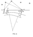
- the laser system may include the facility to form measurements of horizontal angles referenced to a fixed direction such as north. Reference is made to FIG. 6 . Every time the rotating laser passes a reference mark, a unidirectional bank of LEDs are illuminated at the laser transmitter 80. At the laser detector 82, the time between the next laser strike and the LED illumination provides a measure of the angular displacement of the detector from the reference line, given that the rotation rate of the laser transmitter 80 is measured and therefore is known.
- the laser transmitter 80 is arbitrarily aligned such that there is an angular displacement of the device with respect to true north of B degrees. Readings of the angle between the transmitter reference line 84 and the detector 82 are available on each sweep of the laser and are denoted by a i .
- the location of the transmitter 80 is given in terms of three dimensional Cartesian coordinates by X T , Y T , and Z T , while the detector coordinates are X, Y, and Z, as before.
- the angular readings may be input as positional observations into the overall estimation scheme used in a combined laser/GNSS system.
- the least squares approach can be once again applied.
- E T , N T be the planar coordinates of the transmitter and E, N, the coordinates of the detector.
- a i f E 0 N 0 B 0 + df dE ⁇ ⁇ ⁇ E + df dN ⁇ ⁇ ⁇ N + df d ⁇ B ⁇ ⁇ ⁇ B
- E 0 , No, and B 0 are initial guesses for the values of E,N and B, respectively
- df/dE, df/dN, and df/dB are the partial derivatives of the function with respect to each unknown parameter
- ⁇ E, ⁇ N, and ⁇ B are corrections to the initial estimates E 0 , N 0 , and B 0 , that lead to the most probable values of the unknowns.
- a single angle observation from a single transmitter is insufficient for determining the location of the detector. With multiple transmitters, the intersection of two angular observations suffices.
- Equation (2) shows the matrix form of GNSS and laser observations being used to estimate the unknown coordinates of the detector antenna.
- the aforementioned process is based around the assumption that the laser transmitter height and location are known.
- One benefit of a combined laser and GNSS system is that it can be self-calibrating. Instead of solving for just the position of the detector antenna (plus clock and orientation nuisance parameters), it is possible to include the three dimensional position of the laser transmitter as an unknown, as well.
- laser and GNSS position readings must be taken at more than two non-collinear points 90, 92 (i.e., two points that are not aligned) around the transmitter 94 to be able to compute the transmitter location.
- many readings can be taken at a range of points surrounding the transmitter to be able to average out GNSS random errors and small systemic error sources.
- the detector should be placed at points that establish roughly a 90 degree angle at the transmitter. This gives a good fix on the transmitter location.
- GPS observations are normally made at regular time intervals or epochs. Laser readings are dictated by the rotation rate of the transmitter and therefore may not exactly coincide with the GPS observations. There are several ways of handling this situation, assuming that the movement of the receiver is rapid enough that an error may result from a lack of synchronization.
- the rotation rate of the laser transmitter may be increased so that a reading can be taken which is sufficiently close to a GPS epoch that negligible error in position results.
- the motion of the rover can be modeled in a Kalman filter and the GPS and laser detector observations can be fed into the filter whenever they occur.
- the rate of change of the GPS or laser observations can be modeled so that the observations can be skewed to a common epoch. In any case, the GPS and Laser observations can be readily processed together in a consistent manner.
Abstract
Description
- The current invention relates to position tracking and machine control systems, and in particular to a combination of laser systems and global navigation satellite systems to track position and to provide accurate machine control.
- Global navigation satellite systems, like GPS, and GLONASS have been used extensively to determine position coordinates, facilitating surveying and automated control of mobile units. In the future, the European GALILEO system will have similar capabilities. An autonomous navigational system that includes a satellite receiver and a navigational computer can achieve a 10-meter level of accuracy in determining the position of a mobile unit using solely the satellite signals. Differential navigational systems that utilize differential corrections in addition to the satellite signals can determine the positional information to within a meter range of accuracy. Real-time kinematic (RTK) navigational systems that are capable of utilizing both code and carrier information transmitted from such satellites can achieve centimeter level accuracy.
- However, a level of accuracy less than a centimeter has been beyond the reach of typical satellite-based navigational systems. In an attempt to achieve very high accuracy, prior art systems have included rotating laser transmitters that project a plane of light to millimeter level accuracy. However, these prior art laser-based systems cannot be used for the purposes of three dimensional navigation of mobile objects because they are configured to determine only the vertical coordinate with great accuracy.
- It is against the above mentioned background, that the present invention provides a number of unobvious advantages and advances over the prior art. In particular, the present invention discloses a combination laser system and global navigation satellite system that allows a user to realize high precision control of mobile units, including high precision machine control.
- With the combination laser detector and global navigation satellite antenna, the laser height reference detected by the laser detector is provided in a known and fixed relationship with the nominal phase center of the global navigation satellite antenna. Each mobile unit equipped with a combination laser detector and global navigation satellite antenna uses the data from both the laser system and the GPS system to improve its position determination capabilities. The signals received from said laser detector are used to facilitate the determination of the position of the mobile unit based on the signals from the global navigation satellite antenna.
- The aforementioned advantages of the present invention, as well as additional advantages thereof, will be more clearly understood hereinafter as a result of a detailed description of a preferred embodiment of the invention when taken in conjunction with the following drawings, wherein like elements are indicated by like symbols.
-
FIG. 1 shows a position tracking and control (PTC) system according to one embodiment of the present invention wherein the PTC system comprises a laser system, one or more mobile units, each having a combination laser detector and global navigation satellite (CLDGNS) antenna and an associated control system, and a communication link. -
FIGS. 2-4 depict various embodiments of combination laser detector and global navigation satellite antennas according to the present invention. -
FIGS. 5-7 are schematic diagrams useful in explaining the manner in which data from the laser system and data from the global navigation satellite system are combined. An example of a known control system comprising a rotary laser apparatus, an optical sensor, a GPS antenna and an arithmetic operation device, for controlling construction machines is described inUS 2003/137658 A1 . - The present invention can be best understood by focusing on
FIG. 1 which depicts a position tracking and control (PTC)system 10. ThePTC system 10 comprises alaser transmitter system 12, one or more mobile orrover units 14, each having a combination laser detector and global navigation satellite (CLDGNS)antenna 16 and an associatedcontrol system 18, and having a transmitter for establishing acommunication link 20, preferably a radio link.Signals 21 from a plurality ofglobal navigation satellites 22 orbiting the earth, such as GPS, GLONASS, GALILEO, and combinations thereof, are received by the CLDGNSantenna 16 so that the coordinates of dynamic points in a plot ofland 17, such as points indicated as DP1 and DP2, can be determined to a centimeter level of accuracy by thecontrol system 18.Control system 18 includes a microprocessor or other computing hardware configured to process data from theantenna 16 to provide an estimate of the position of theantenna 16. - Millimeter level of accuracy in determining the position of the dynamic points DP1 and DP2 relative to each
CLDGNS antenna 16 is provided by thecontrol system 18 which uses information provided by thelaser system 12 in its coordinate (x, y, z) position computation in addition to signals received fromsatellites 22. In one embodiment, thelaser system 12 provides at least two diverging or fan-shaped beams 23 and 23' that rotate continuously about a vertical axis Z0 at a uniform rate above a known stationary point SP in the plot ofland 17. The fan-shaped beams 23 and 23' project from thelaser system 12 in non-vertical planes, such that thefirst fan beam 23 will intersect an arbitraryhorizontal reference plane 24 at an angle α, and the second fan shaped beam 23' will intersect the horizontal reference plane at an angle β. Dynamic point DP1, may be a working element on a machine, such as a grader blade, while dynamic point DP2 may be a point at the bottom of a manually positioned mast being moved about by a surveyor. - It is to be appreciated that the fan-
shaped beams 23 and 23', if rotated at a constant speed about a vertical axis, will activate one after another (with some delay of time therebetween) at least one optical sensor 44 (FIGS. 2-4 ) of eachCLDGNS antenna 16. Further, it is to be appreciated that in the embodiment ofFIG. 1 , the time delay between activating theoptical sensor 44 by each fan-shaped beam 23 and 23' will increase or decrease as the relative position of aCLDGNS antenna 16 moves above or below thehorizontal reference plane 24, respectively. It is to be appreciated that theCLDGNS antenna 16 can be initialized to any arbitraryhorizontal reference plane 24 simply by selecting and entering into the control system 18 a detection time delay. Additionally, it is to be appreciated that any detected change by theCLDGNS antenna 16 in the detection time delay is related to an angle γ, which is the angle at which a straight line passing through the optical sensor 44 (FIGS. 2-4 ) of theCLDGNS antenna 16 and the point of emanation of the fan-shaped beams 23 and 23' meets the selected arbitraryhorizontal reference plane 24. - As mentioned above, angles a and β are constants. Angle γ is determined by sensing the timing between the illumination of the
sensor 44 by thebeams 23 and 23'. The higher thesensor 44, the greater the delay. It will be apparent that fluctuation in the rotation speed of the fan-shaped beams 23 and 23' will introduce short term, transient errors. To minimize such errors, thecontrol processor 18 may be provided with the rotation speed of thelaser system 12 via thecommunication link 20. The rotation speed may, however, be phase locked to a crystal oscillator, providing sufficient accuracy. Accordingly, knowing the rotation speed, thecontrol system 18 can compute the value of angle γ arithmetically from the detected time delay between illumination by thebeams 23 and 23', and thus the elevation angle of the optical sensor in theCLDGNS antenna 16 above the referencehorizontal plane 24 is determined. - In another embodiment, the
laser system 12 is further provided with a plurality of light sources which are strobed at the same point in time during each rotation of thebeams 23 and 23'. Beacon 26 provides a simultaneous 360°flash 38 at a different wavelength than the fan shapedbeams 23 and 23'. By orientating thelaser system 12 such that thebeacon 26 flashes as the mid point between the fan-shaped beams 23 and 23' passes a known true heading A0 , thecontrol system 18 can also compute a relative bearing to thelaser system 12 from the time delay between detecting thesignal 38 of the beacon and detecting the fan-shaped beams 23 and 23'. - In still another embodiment, the
laser system 12 is provided with a global navigation satellite system (GNSS)receiver 30. The GNSSreceiver 30 can receive and compute its position from thesignals 21 provided by theglobal navigation satellites 22. A detailed discussion of how to determine a location from such signals is disclosed byU.S. Patent No. 6,433,866 , also assigned to Trimble Navigation, LTD. - The
control system 18 in addition to knowing its own position (as computed from the detected satellite signals received and provided by the CLDGNS antenna 16), is provided also with the known and fixed position of thelaser system 12 via thecommunication link 20. Using the information provided by thelaser system 12 for correlation and error correcting, thecontrol system 18 can then compute the coordinate (x, y, z) position of any dynamic point relative to theCLDGNS antenna 16 to a high degree of accuracy. A more detail discussion of the computations performed by thecontrol system 18 is disclosed below. - It is to be appreciated that the
PTC system 10 provides a number of benefits to a potential mobile user by integrating a laser detector and a global navigation satellite antenna. For example, the CLDGNSantenna 16 costs less than separate laser detectors and global navigation satellite antennas because the integrated CLDGNS antenna requires only one set of packaging, and can utilize shared circuitry and wiring, computer memory and processing, and a common power supply. Other benefits are disclosed with reference made toFIGS. 2-4 which illustrate various embodiments of the combination laser detector and global navigation satellite antenna according to the present invention. -
FIG. 2 illustrates diagrammatically one embodiment of a CLDGNSantenna 16 which provides anantenna element 32 mounted to anelectronic housing 34, which in turn is mounted to an end of anelongated support 36, such as a mast. Within thehousing 34, theantenna element 32 is coupled to a low noise amplifier (LNA) 38, and alaser detector 40 is coupled to alaser signal processor 42. Thelaser detector 40 may include a number ofoptical sensors 44 placed around the periphery of thehousing 34. Theoptical sensors 44 face generally downward and outward. In this orientation, at least one of theoptical sensors 44 will detect the fan-shaped beams 23 and 23' from thelaser system 12, and two or moreoptical sensors 44 will detect the fan-shaped beam some of the time. Eachoptical sensor 44 can be read independently and its position calculated by thecontrol system 18. - In the illustrated embodiment of
FIG. 2 , threeoptical sensors 44 are provided, and in other embodiments more may be included to improve laser detection, if desired. In such embodiments, with the relative positions X0, Y0, and Z0 of eachoptical sensor 44 to the nominal phase center x of itsrespective antenna element 32 being known, transposing the detected laser position of eachoptical sensor 44 to the nominal phase center x of theantenna element 32 is easily computed arithmetically by thecontrol system 18. - The difference in the detected elevation between at the three
optical sensors 44 provides an indication of tilt, which in turn may be used by thecontrol system 18 to compensate for errors that would otherwise result in the calculated position of DP1 and DP2. Additionally, although the antenna tilt angle is important for adjusting the detected laser heights of eachoptical sensor 44 to the nominal phase center x of the associatedantenna element 32, these changes in detected laser heights can also be used to help determine the orientation of the device (such as a grader/bulldozer blade) to which theCLDGNS antenna 16 may be connected. However, if desired, a tilt/heading sensor 46 may be further included in the packaging of theCLDGNS antenna 16 to simplify further the compensation for tilt, error correcting, and device orientation determination. - In another embodiment of the CLDGNS
antenna 16, illustrated byFIG. 3 , theelectronic housing 34 and theantenna element 32 are protected by aradome 46. A fiber optic pick-up 48 of the laser detector is positioned on the top of theradome 46. The fiber-optic pick-up 48 is small, about 0.25 inches (6 mm) in diameter, as it only needs to collect enough energy to activate theoptical sensor 44. The non-metallic fiber optic pick-up 48 is orientated along the Z axis, aligned vertically with the nominal phase center x of theantenna element 32. The laser detector also includesoptical fiber 50 coupling the fiber optic pick-up 48 to theoptical sensor 44. In this embodiment, theoptical sensor 44 is positioned below theantenna element 32. Afilter 52 may be optionally provided to filter out light noise received by the fiber optic pick-up 48. This improves the sensitivity of theoptical sensor 44 to the energy of the fan-shapedbeams 23 and 23' (FIG. 1 ). - In one embodiment, the fiber optic pick-
up 48 comprises a circularly symmetric hyperbolic mirrored surface 54 (FIG. 3a ) that catches light from 360 degrees, and reflects it to theoptical sensor 44, via theoptical fibers 50. In another embodiment, the fiber optic pick-up 48 may comprises a TIR prism 56 (FIG. 3b ) which redirects the laser energy to theoptical sensor 44, viaoptical fiber 50. The use of a total internal reflection (TIR)prism 56 requires no metallic coatings to ensure reflectivity, thereby removing all metal from above theantenna element 32. Since the metallic and semi-metallic portions of theoptical sensor 44 are located below theantenna element 32, they will not adversely affect the ability of theantenna 16 to pick up the relatively weak satellite signals 21. Cabling 58 is provided through thesupport 36 to connect the output of theCLDGNS antenna 16 to the control system 18 (FIG. 1 ). - In yet another embodiment, illustrated by
FIG. 4 , one or more sensors 60 are located below theelectronics housing 34, spaced along thesupport 36. This arrangement for the sensors 60 has the advantage of not interfering with reception, and also of not affecting the location of the nominal phase center x of theantenna element 32. Each sensor 60 may comprise a circularly symmetric hyperbolic mirrored surface or a prism. Because each sensor 60 is below theantenna element 32, fiber optics may not be required since the sensors may be integrated closely with the detectors. Afilter 52 may be provided to filter out extraneous energy to improve sensitivity to laser light. The output signals from the detectors in all the above disclosed embodiments are coupled to associatedprocessors 42. The output ofprocessor 42 is included in the output of theCLDGNS antenna 16 and provided to thecontrol system 18 for further use and evaluation. - In the embodiment of
Fig. 4 , the sensors 60 may be provided at known positions along thesupport 36. Information provided by the sensors 60 can be used by thecontrol system 18 to determine the distance from thetransmitter 12 to the sensors 60. Since computation is well known to those skilled in the art, no further discussion is provided. This co-axial alignment simplifies implementation though non-co-axial implementations are also possible. - In the above disclosed embodiments of the CLDGNS antenna 16 (
FIGS. 1-4 ), each of the laser detectors and the nominal phase center x of the antenna element are separated by a known, fixed distance and are generally aligned co-axially. In particular, the Z0 distance (and the X0, Y0 distances, if necessary) of eachoptical sensor 44 relative to the nominal phase center x of theantenna element 32 are factory set. Accordingly, theCLDGNS antenna 16 improves the accuracy of thePTC system 10 by preventing an operator from manually entering a positional error intocontrol system 18 due to a miscalculated measurement between the optical sensors of the laser detector and the nominal phase center x of the antenna element. - In the above embodiments, the
CLDGNS antenna 16 is illustrated as having either a geodesic shape or a generally flat disc shape. However, it is to be appreciated that other satellite antennas may also be used advantageously with the concepts of the present invention. - Reference is made to
FIG. 5 which illustrates a GNSS and laser system. Abase GNSS receiver 70 is located at a known mark and tracks the satellites in view. Range and/or carrier phase measurements are taken by thebase receiver 70 and transmitted to the mobile orrover GNSS receiver 72. Themobile GNSS receiver 72 tracks two or more GNSS satellites that are also tracked by thebase receiver 70. Alternatively, a network of base GNSS receivers can be used to generate a data stream that is largely corrected for atmospheric and satellite error sources. This approach is termed Network Real-Time Kinematic positioning and has position accuracy advantages over systems that use a single base receiver. - A
laser transmitter 74 is located on site and provides suitable coverage for thelaser detector 76. The elevation of thelaser transmitter 70 relative to the same datum as the GNSS is known. In the case of GPS, the reference spheroid is the World Geodetic System 1984. Thelaser detector 76 senses the signals sent from thetransmitter 74 and determines the difference in elevation relative to thetransmitter 74. The laser transmitter aligns itself with the instantaneous direction of gravity and will not in general accord with the direction of a normal to the spheroid at the same point. Fortunately, the reference spheroid sufficiently well approximates the physical earth (mean sea level), particularly given that the operating range of the laser is less than 500 meters. As a result, the height difference obtained from the laser system, will be compatible with changes in height determined from the GNSS. - Let r1, r2, .. rs be the range observations from the mobile GNSS antenna to
satellites - The satellite coordinates are known and are obtained via an ephemeris, typically broadcast by each satellite. The satellite coordinates are given in terms of WGS84 XYZ Cartesian form (i.e., Xi, Yi, Zi, where i=1,2..s).
- Laser height readings taken at the
mobile detector 76 provide the difference in elevation (ΔH) to the Laser Transmitter. This height difference must then be applied to the height of the Laser transmitter above the reference spheroid (HT) to obtain the height of thelaser detector 76 above the spheroid (HD). The distance from the center of the spheroid tolaser detector 76 is computed by adding HT to the radius of curvature of spheroid at the mobile unit. Finally, the distance from the center of the spheroid to the GNSS antenna is generated by applying any height offset betweenlaser detector 76 and antenna for the receiver 72 - the final range measurement (rL) is compatible with those obtained from GNSS. Hence, the laser height input can be considered as an additional satellite observation, with the satellite located at the center of the earth. - We next apply least squares estimation to estimate the X, Y, and Z coordinates of the mobile unit (plus the receiver clock bias term T). The observation equations needed for the process are common to both GNSS and laser data and can be presented in linearised form as:

- li
- is a vector of observation minus computed terms for each satellite (i=1,2..s) and the laser-detector (i=L). The approximate coordinates of the rover (X0, Yo, Z0) are used to form the computed (theoretical) range values, Ri;
- vi
- is a vector of observation residuals that recognize that the observations are not perfect, but are affected by small errors;
- A
- is a design matrix that relates the observations with the unknowns; and
- x
- is a vector of corrections to the approximate rover antenna coordinates and the approximate GNSS receiver clock bias term (T0).
- The components of equation (1) are presented in full matrix form below:

- The design matrix terms ai, bi, ci are the direction cosines for the range observations from the
rover antenna 72 to satellites (for GNSS observations) and from therover antenna 72 to the center of the spheroid (for laser observations). The direction cosines are computed using:
- Each observation presented in equation (1) has an associated uncertainty. In the case of the GNSS phase observations, this is normally on the order of a centimeter. In the case of laser height readings, it is on the order of a few millimeters. Hence, an observation weight matrix is introduced that is formed by the inverse of the individual observation variances:

- Based on the principle of least squares, the most-probable value of the corrections to the unknowns are obtained by minimizing the sum of the squares of the weighted observation residuals according to:

- Finally, the corrected coordinates and clock bias term (denoted with a superscript ^) of the rover are obtained by applying the result of equation (5) to the respective approximate values used as the linearization point for the adjustment:

- The laser system may include the facility to form measurements of horizontal angles referenced to a fixed direction such as north. Reference is made to
FIG. 6 . Every time the rotating laser passes a reference mark, a unidirectional bank of LEDs are illuminated at thelaser transmitter 80. At the laser detector 82, the time between the next laser strike and the LED illumination provides a measure of the angular displacement of the detector from the reference line, given that the rotation rate of thelaser transmitter 80 is measured and therefore is known. - In
FIG. 6 , thelaser transmitter 80 is arbitrarily aligned such that there is an angular displacement of the device with respect to true north of B degrees. Readings of the angle between the transmitter reference line 84 and the detector 82 are available on each sweep of the laser and are denoted by ai. The location of thetransmitter 80 is given in terms of three dimensional Cartesian coordinates by XT, YT, and ZT, while the detector coordinates are X, Y, and Z, as before. - The angular readings may be input as positional observations into the overall estimation scheme used in a combined laser/GNSS system. The least squares approach can be once again applied. For simplicity, consider the unknown coordinates of the detector in terms of a horizontal plane centered on the
transmitter 80. Let ET, NT be the planar coordinates of the transmitter and E, N, the coordinates of the detector. The observation equation that links the angular observations with the detector coordinates is given below:
- Each angular observation is subject to a small, random error wi. It is possible that the laser transmitter will be manually aligned to north in the field, in which case B will be identically zero. For the purposes of the discussion, below, it is worthwhile considering B as an unknown parameter that can be determined via the integration of GPS and laser devices.
- The three unknown parameters in equation (7) are E, N, and B:

- In order to apply the theory of least squares we must linearize the observation equation:


- If our initial guess for E, N and B is very good, then αo will be very close to the actual observed angle αi. The partial derivatives of the observation equation with respect to the unknowns are given by:


- A single angle observation from a single transmitter is insufficient for determining the location of the detector. With multiple transmitters, the intersection of two angular observations suffices.
- Equation (2) shows the matrix form of GNSS and laser observations being used to estimate the unknown coordinates of the detector antenna. Now we wish to integrate the angular observations into the combined solution for the coordinates of the detector and therefore we need to convert the angular observation development from the E, N plane system to X, Y, and Z Cartesian coordinates. The two coordinate systems are related via the following rotation matrix:

- The rotation matrix contains trigonometric values relating to the latitude (φ), and longitude (λ) of the transmitter. Equation (14) can be used in equation (7) to produce a new angle observation equation that relates to the same coordinate system as that used for GNSS data:

- In equation (15), the XT, YT, ZT and φ, λ coordinates of the transmitter are assumed to be known and are a function of: X, Y, Z and B:

- A linearization process is used to produce an observation equation that can be applied in a least squares estimation scheme:

- The partial derivatives in equation (17) involving trig functions are straightforward to compute, and are therefore omitted here.
- We now have all of the components needed to state the matrix form of the observation equations for combined GNSS, laser height and laser direction data:

- An observation weight must be assigned to the angle measurement shown in equation (18). Then, the best estimates of the corrections to the coordinates, GNSS receiver clock, and laser transmitter orientation are obtained using the matrix expression (5). Finally, the best estimates of the parameters are computed by applying the corrections to their approximate values:

- The aforementioned process is based around the assumption that the laser transmitter height and location are known. One benefit of a combined laser and GNSS system, is that it can be self-calibrating. Instead of solving for just the position of the detector antenna (plus clock and orientation nuisance parameters), it is possible to include the three dimensional position of the laser transmitter as an unknown, as well. As shown in
FIG. 7 , laser and GNSS position readings must be taken at more than two non-collinear points 90, 92 (i.e., two points that are not aligned) around thetransmitter 94 to be able to compute the transmitter location. Preferably, many readings can be taken at a range of points surrounding the transmitter to be able to average out GNSS random errors and small systemic error sources. Where possible, the detector should be placed at points that establish roughly a 90 degree angle at the transmitter. This gives a good fix on the transmitter location. - GPS observations are normally made at regular time intervals or epochs. Laser readings are dictated by the rotation rate of the transmitter and therefore may not exactly coincide with the GPS observations. There are several ways of handling this situation, assuming that the movement of the receiver is rapid enough that an error may result from a lack of synchronization. First, the rotation rate of the laser transmitter may be increased so that a reading can be taken which is sufficiently close to a GPS epoch that negligible error in position results. Second, the motion of the rover can be modeled in a Kalman filter and the GPS and laser detector observations can be fed into the filter whenever they occur. Third, the rate of change of the GPS or laser observations can be modeled so that the observations can be skewed to a common epoch. In any case, the GPS and Laser observations can be readily processed together in a consistent manner.
- Although the present invention has been described in terms of the presently preferred embodiments, it is to be understood that the disclosure is not to be interpreted as limiting. For example, the optical sensor and the GPS antenna are described as being mounted on the machine in one embodiment, and this is intended to include mounting these components on the body of the machine, or on the machine implement for movement therewith. Various alterations and modifications will no doubt become apparent to those skilled in the art after having read the above disclosure.
Claims (8)
- A system for determining position, having a laser transmitter (12) that projects at least one laser beam (23) that rotates about a generally vertical axis (Zo), a GPS receiver for determining position, the GPS receiver having a GPS antenna (32), an optical sensor (44) for receiving the laser beam, and a device (18) receiving signals from the GPS receiver and signals from the optical sensor to determine the position of the sensor and the receiver, said system characterised in that:said optical sensor (44) is coaxial with, and at, or displaced a small distance from, the phase center of said GPS antenna (32), and said device (18) utilizing signals received from the optical sensor to improve the estimate of position based on said signals from said GPS receiver.
- The system of claim 1 further characterised in that said laser transmitter projects a pair of fan shaped beams (23, 23') of laser light, and said optical sensor is responsive to both of said beams.
- The system of claim 1 further characterised in that said GPS antenna and said optical sensor (44) are located on the same mast (36) in close proximity.
- The system of claim 1 further characterised in that a least squares approximation is utilized to determine the most likely position, based on the detection signals from the optical sensor (44) and the GPS receiver.
- The system of claim 2 further characterised in that said system determines the position of a machine (14) and controls the position of the machine, said GPS antenna (32) and said optical sensor (44) being mounted on the machine (14), and said device (18) being mounted on the machine and receiving a signal from the GPS receiver and a signal from the optical sensor (44), to determine the position of the machine (14) from a combination of all of the signals and for providing a control signal.
- The system of claim 5 further characterised in that said GPS antenna and said optical sensor are mounted on said machine (14) in close, fixed proximity to each other, and said GPS antenna (32) and said optical sensor (44) are mounted for movement with an implement of said machine (14).
- The system of claim 6 further characterised in that said device on the machine effects control of the position of said implement based on a sensed position and a desired position.
- The system of claim 1 further characterised in that said GPS receiver provides first data for position estimation in response to reception of signals from a plurality of satellites (22), said optical sensor (44) provides second data for position estimation, and said device (18) comprises a microprocessor, responsive to said first data and said second data to determine an estimate of the position of said receiver and said antenna by combining said second data and said first data before determination of said estimate position.
Applications Claiming Priority (2)
| Application Number | Priority Date | Filing Date | Title |
|---|---|---|---|
| US10/890,037 US20060012777A1 (en) | 2004-07-13 | 2004-07-13 | Combination laser system and global navigation satellite system |
| PCT/US2005/017542 WO2006016935A1 (en) | 2004-07-13 | 2005-05-19 | Combination laser system and global navigation satellite system |
Publications (2)
| Publication Number | Publication Date |
|---|---|
| EP1774257A1 EP1774257A1 (en) | 2007-04-18 |
| EP1774257B1 true EP1774257B1 (en) | 2011-07-13 |
Family
ID=35229854
Family Applications (1)
| Application Number | Title | Priority Date | Filing Date |
|---|---|---|---|
| EP05772516A Active EP1774257B1 (en) | 2004-07-13 | 2005-05-19 | Combination laser system and global navigation satellite system |
Country Status (4)
| Country | Link |
|---|---|
| US (2) | US20060012777A1 (en) |
| EP (1) | EP1774257B1 (en) |
| CN (1) | CN101010563A (en) |
| WO (1) | WO2006016935A1 (en) |
Families Citing this family (41)
| Publication number | Priority date | Publication date | Assignee | Title |
|---|---|---|---|---|
| US8478492B2 (en) | 1998-11-27 | 2013-07-02 | Caterpillar Trimble Control Technologies, Inc. | Method and system for performing non-contact based determination of the position of an implement |
| US8705022B2 (en) * | 2004-07-13 | 2014-04-22 | Trimble Navigation Limited | Navigation system using both GPS and laser reference |
| US7764365B2 (en) * | 2004-07-23 | 2010-07-27 | Trimble Navigation Limited | Combination laser detector and global navigation satellite receiver system |
| US10458099B2 (en) | 2004-08-26 | 2019-10-29 | Caterpillar Trimble Control Technologies Llc | Auto recognition of at least one standoff target to determine position information for a mobile machine |
| US7116269B2 (en) * | 2005-02-15 | 2006-10-03 | Trimble Navigation, Ltd | Radio and light based three dimensional positioning system |
| EP1929125B1 (en) * | 2005-08-23 | 2009-08-05 | The Charles Machine Works Inc | System for tracking and maintaining an on-grade horizontal borehole |
| US7787134B2 (en) * | 2005-11-09 | 2010-08-31 | The Boeing Company | Multiple fanned laser beam metrology system |
| US20080047170A1 (en) | 2006-08-24 | 2008-02-28 | Trimble Navigation Ltd. | Excavator 3D integrated laser and radio positioning guidance system |
| US7617061B2 (en) * | 2006-11-03 | 2009-11-10 | Topcon Positioning Systems, Inc. | Method and apparatus for accurately determining height coordinates in a satellite/laser positioning system |
| WO2009039466A1 (en) | 2007-09-20 | 2009-03-26 | Vanderbilt University | Free solution measurement of molecular interactions by backscattering interferometry |
| EP2040030A1 (en) * | 2007-09-24 | 2009-03-25 | Leica Geosystems AG | Positioning method |
| FR2931451B1 (en) * | 2008-05-22 | 2010-12-17 | Fmc Technologies Sa | CONTROL DEVICE FOR SYSTEM FOR LOADING AND / OR UNLOADING FLUIDS |
| US9250328B2 (en) * | 2009-09-30 | 2016-02-02 | Javad Gnss, Inc. | Graphics-aided remote position measurement with handheld geodesic device |
| IL203105A (en) * | 2009-12-31 | 2016-12-29 | Tomer Bruchiel | System and method for accurately directing antennas |
| WO2011156713A1 (en) | 2010-06-11 | 2011-12-15 | Vanderbilt University | Multiplexed interferometric detection system and method |
| US8125376B1 (en) | 2010-08-30 | 2012-02-28 | Javad Gnss, Inc. | Handheld global positioning system device |
| CN102102989B (en) * | 2010-12-13 | 2012-08-22 | 浙江大学 | Vortex phase plate-based laser beam reference calibration method and device |
| US9562853B2 (en) | 2011-02-22 | 2017-02-07 | Vanderbilt University | Nonaqueous backscattering interferometric methods |
| GB201103822D0 (en) * | 2011-03-07 | 2011-04-20 | Isis Innovation | System for providing locality information and associated devices |
| US9228835B2 (en) | 2011-09-26 | 2016-01-05 | Ja Vad Gnss, Inc. | Visual stakeout |
| TWI439834B (en) | 2011-12-29 | 2014-06-01 | Ind Tech Res Inst | Method and system for navigation of movable platform |
| CN103292821B (en) * | 2012-03-01 | 2017-05-24 | 深圳光启创新技术有限公司 | Locating device |
| US9273949B2 (en) | 2012-05-11 | 2016-03-01 | Vanderbilt University | Backscattering interferometric methods |
| JP6275423B2 (en) * | 2013-09-06 | 2018-02-07 | 株式会社Nttドコモ | Wireless base station, wireless communication system, and wireless communication method |
| US9470511B2 (en) | 2013-11-12 | 2016-10-18 | Trimble Navigation Limited | Point-to-point measurements using a handheld device |
| CN103606738B (en) * | 2013-11-16 | 2015-11-18 | 浙江中星光电子科技有限公司 | A kind of satellite antenna on mobile vehicle and control method thereof |
| CN104679015A (en) * | 2013-11-28 | 2015-06-03 | 哈尔滨市三和佳美科技发展有限公司 | Laser automatic alignment communication apparatus |
| JP6323026B2 (en) * | 2014-01-22 | 2018-05-16 | 株式会社デンソー | Position estimation system |
| EP3196594B1 (en) | 2014-05-05 | 2021-08-11 | Hexagon Technology Center GmbH | Surveying system |
| CN104535053B (en) * | 2015-01-09 | 2016-10-12 | 中国人民解放军军械工程学院 | Gun rotated accuracy detecting system based on satellite fix |
| WO2016118812A1 (en) | 2015-01-23 | 2016-07-28 | Vanderbilt University | A robust interferometer and methods of using same |
| US20170133739A1 (en) * | 2015-11-10 | 2017-05-11 | Caterpillar Inc. | Fixture for locating an antenna |
| US10627396B2 (en) | 2016-01-29 | 2020-04-21 | Vanderbilt University | Free-solution response function interferometry |
| US10424784B2 (en) * | 2016-10-28 | 2019-09-24 | GM Global Technology Operations LLC | Negative electrode including silicon nanoparticles having a carbon coating thereon |
| CN110325821B (en) * | 2017-02-14 | 2021-12-07 | 天宝公司 | Geodetic surveying with time synchronization |
| JP6775447B2 (en) * | 2017-03-08 | 2020-10-28 | 三菱電機株式会社 | Calibration device, position calculation device and calibration method |
| US10859702B1 (en) | 2017-12-21 | 2020-12-08 | Facebook Technologies, Llc | Positional tracking using retroreflectors |
| CN109724577B (en) * | 2019-01-30 | 2022-02-11 | 山东省国土测绘院 | Water depth data processing method combining single-beam and towing measurement |
| CN109655034B (en) * | 2019-02-03 | 2022-03-11 | 美国西北仪器公司 | Rotary laser device and laser ranging method |
| US11536857B2 (en) | 2019-12-19 | 2022-12-27 | Trimble Inc. | Surface tracking on a survey pole |
| CN113558522B (en) * | 2020-04-29 | 2022-10-11 | 尚科宁家(中国)科技有限公司 | Traveling control method applied to cleaning robot and cleaning robot |
Family Cites Families (11)
| Publication number | Priority date | Publication date | Assignee | Title |
|---|---|---|---|---|
| US5640323A (en) * | 1990-02-05 | 1997-06-17 | Caterpillar Inc. | System and method for operating an autonomous navigation system |
| US5268695A (en) * | 1992-10-06 | 1993-12-07 | Trimble Navigation Limited | Differential phase measurement through antenna multiplexing |
| US5652592A (en) * | 1995-06-06 | 1997-07-29 | Sanconix, Inc | Radio location with enhanced Z-axis determination |
| US5848485A (en) * | 1996-12-27 | 1998-12-15 | Spectra Precision, Inc. | System for determining the position of a tool mounted on pivotable arm using a light source and reflectors |
| US6433866B1 (en) * | 1998-05-22 | 2002-08-13 | Trimble Navigation, Ltd | High precision GPS/RTK and laser machine control |
| JP4090119B2 (en) * | 1998-06-17 | 2008-05-28 | 株式会社トプコン | Rotating laser device |
| US5949371A (en) * | 1998-07-27 | 1999-09-07 | Trimble Navigation Limited | Laser based reflectors for GPS positioning augmentation |
| US6259403B1 (en) * | 1999-08-09 | 2001-07-10 | Trimble Navigation Limited | GPS positioning utilizing laser based reflectors augmentation |
| JP4601798B2 (en) * | 2000-10-06 | 2010-12-22 | 株式会社トプコン | Position measurement setting system |
| JP3816806B2 (en) * | 2002-01-21 | 2006-08-30 | 株式会社トプコン | Construction machine control system |
| GB2395261A (en) * | 2002-11-11 | 2004-05-19 | Qinetiq Ltd | Ranging apparatus |
-
2004
- 2004-07-13 US US10/890,037 patent/US20060012777A1/en not_active Abandoned
-
2005
- 2005-05-19 WO PCT/US2005/017542 patent/WO2006016935A1/en active Application Filing
- 2005-05-19 EP EP05772516A patent/EP1774257B1/en active Active
- 2005-05-19 CN CNA2005800298096A patent/CN101010563A/en active Pending
-
2008
- 2008-03-19 US US12/051,508 patent/US20080158044A1/en not_active Abandoned
Also Published As
| Publication number | Publication date |
|---|---|
| US20060012777A1 (en) | 2006-01-19 |
| WO2006016935A1 (en) | 2006-02-16 |
| US20080158044A1 (en) | 2008-07-03 |
| CN101010563A (en) | 2007-08-01 |
| EP1774257A1 (en) | 2007-04-18 |
Similar Documents
| Publication | Publication Date | Title |
|---|---|---|
| EP1774257B1 (en) | Combination laser system and global navigation satellite system | |
| US8705022B2 (en) | Navigation system using both GPS and laser reference | |
| US7764365B2 (en) | Combination laser detector and global navigation satellite receiver system | |
| US6727849B1 (en) | Seamless surveying system | |
| US5379045A (en) | SATPS mapping with angle orientation calibrator | |
| US5077557A (en) | Surveying instrument with receiver for satellite position-measuring system and method of operation | |
| US8271194B2 (en) | Method and system using GNSS phase measurements for relative positioning | |
| US6732051B1 (en) | Seamless surveying system | |
| US6304210B1 (en) | Location and generation of high accuracy survey control marks using satellites | |
| EP0870173B1 (en) | Improved vehicle navigation system and method | |
| US7742176B2 (en) | Method and system for determining the spatial position of a hand-held measuring appliance | |
| EP0706665A1 (en) | Integrated terrestrial survey and satellite positioning system | |
| US5760748A (en) | Pivoting support bracket to mount a GPS antenna above a theodolite or a total station mounted on a tripod | |
| US20090024325A1 (en) | AINS enhanced survey instrument | |
| US6381006B1 (en) | Spatial positioning | |
| US7456943B1 (en) | Laser positioning measurement system and method | |
| AU2020103096A4 (en) | Movements/shifts/displacements monitoring SMART box of Earth Retaining Structures in Landslides Mitigation | |
| US6590834B1 (en) | Local positioning system using acoustic time-of-flight and a fixed array of receivers and method for use | |
| US5835069A (en) | GPS antennas and receivers configured as handles for a surveyor's optical total station | |
| US20050128126A1 (en) | Method for interferometric radar measurement | |
| Nebot | Sensors used for autonomous navigation | |
| Ogaja | A framework in support of structural monitoring by real time kinematic gps and multisensor data | |
| JP2911363B2 (en) | High-accuracy high-speed surveying method and device using satellite | |
| JP3474658B2 (en) | Hazardous area remote surveying method | |
| GB2259822A (en) | Df method |
Legal Events
| Date | Code | Title | Description |
|---|---|---|---|
| PUAI | Public reference made under article 153(3) epc to a published international application that has entered the european phase |
Free format text: ORIGINAL CODE: 0009012 |
|
| 17P | Request for examination filed |
Effective date: 20070208 |
|
| AK | Designated contracting states |
Kind code of ref document: A1 Designated state(s): DE FR |
|
| DAX | Request for extension of the european patent (deleted) | ||
| RBV | Designated contracting states (corrected) |
Designated state(s): DE FR |
|
| 17Q | First examination report despatched |
Effective date: 20081114 |
|
| GRAP | Despatch of communication of intention to grant a patent |
Free format text: ORIGINAL CODE: EPIDOSNIGR1 |
|
| GRAS | Grant fee paid |
Free format text: ORIGINAL CODE: EPIDOSNIGR3 |
|
| GRAA | (expected) grant |
Free format text: ORIGINAL CODE: 0009210 |
|
| AK | Designated contracting states |
Kind code of ref document: B1 Designated state(s): DE FR |
|
| REG | Reference to a national code |
Ref country code: DE Ref legal event code: R096 Ref document number: 602005029000 Country of ref document: DE Effective date: 20110901 |
|
| PLBE | No opposition filed within time limit |
Free format text: ORIGINAL CODE: 0009261 |
|
| STAA | Information on the status of an ep patent application or granted ep patent |
Free format text: STATUS: NO OPPOSITION FILED WITHIN TIME LIMIT |
|
| 26N | No opposition filed |
Effective date: 20120416 |
|
| REG | Reference to a national code |
Ref country code: DE Ref legal event code: R097 Ref document number: 602005029000 Country of ref document: DE Effective date: 20120416 |
|
| REG | Reference to a national code |
Ref country code: FR Ref legal event code: ST Effective date: 20130131 |
|
| PG25 | Lapsed in a contracting state [announced via postgrant information from national office to epo] |
Ref country code: FR Free format text: LAPSE BECAUSE OF NON-PAYMENT OF DUE FEES Effective date: 20120531 |
|
| PGFP | Annual fee paid to national office [announced via postgrant information from national office to epo] |
Ref country code: DE Payment date: 20230530 Year of fee payment: 19 |