WO2016118812A1 - A robust interferometer and methods of using same - Google Patents

A robust interferometer and methods of using same Download PDF

Info

Publication number
WO2016118812A1
WO2016118812A1 PCT/US2016/014439 US2016014439W WO2016118812A1 WO 2016118812 A1 WO2016118812 A1 WO 2016118812A1 US 2016014439 W US2016014439 W US 2016014439W WO 2016118812 A1 WO2016118812 A1 WO 2016118812A1
Authority
WO
WIPO (PCT)
Prior art keywords
channel
sample
light beam
light
further aspect
Prior art date
Application number
PCT/US2016/014439
Other languages
French (fr)
Inventor
Darryl J. Bornhop
Michael Kammer
Original Assignee
Vanderbilt University
Priority date (The priority date is an assumption and is not a legal conclusion. Google has not performed a legal analysis and makes no representation as to the accuracy of the date listed.)
Filing date
Publication date
Application filed by Vanderbilt University filed Critical Vanderbilt University
Priority to JP2017538694A priority Critical patent/JP2018506715A/en
Priority to EP16740808.7A priority patent/EP3247988A4/en
Priority to US15/199,417 priority patent/US10261013B2/en
Publication of WO2016118812A1 publication Critical patent/WO2016118812A1/en
Priority to IL253607A priority patent/IL253607A0/en
Priority to US16/267,311 priority patent/US11293863B2/en

Links

Classifications

    • GPHYSICS
    • G01MEASURING; TESTING
    • G01NINVESTIGATING OR ANALYSING MATERIALS BY DETERMINING THEIR CHEMICAL OR PHYSICAL PROPERTIES
    • G01N21/00Investigating or analysing materials by the use of optical means, i.e. using sub-millimetre waves, infrared, visible or ultraviolet light
    • G01N21/17Systems in which incident light is modified in accordance with the properties of the material investigated
    • G01N21/41Refractivity; Phase-affecting properties, e.g. optical path length
    • G01N21/45Refractivity; Phase-affecting properties, e.g. optical path length using interferometric methods; using Schlieren methods
    • GPHYSICS
    • G01MEASURING; TESTING
    • G01BMEASURING LENGTH, THICKNESS OR SIMILAR LINEAR DIMENSIONS; MEASURING ANGLES; MEASURING AREAS; MEASURING IRREGULARITIES OF SURFACES OR CONTOURS
    • G01B9/00Measuring instruments characterised by the use of optical techniques
    • G01B9/02Interferometers
    • G01B9/02001Interferometers characterised by controlling or generating intrinsic radiation properties
    • GPHYSICS
    • G01MEASURING; TESTING
    • G01NINVESTIGATING OR ANALYSING MATERIALS BY DETERMINING THEIR CHEMICAL OR PHYSICAL PROPERTIES
    • G01N21/00Investigating or analysing materials by the use of optical means, i.e. using sub-millimetre waves, infrared, visible or ultraviolet light
    • G01N21/75Systems in which material is subjected to a chemical reaction, the progress or the result of the reaction being investigated
    • GPHYSICS
    • G01MEASURING; TESTING
    • G01NINVESTIGATING OR ANALYSING MATERIALS BY DETERMINING THEIR CHEMICAL OR PHYSICAL PROPERTIES
    • G01N21/00Investigating or analysing materials by the use of optical means, i.e. using sub-millimetre waves, infrared, visible or ultraviolet light
    • G01N21/17Systems in which incident light is modified in accordance with the properties of the material investigated
    • G01N21/41Refractivity; Phase-affecting properties, e.g. optical path length
    • G01N21/45Refractivity; Phase-affecting properties, e.g. optical path length using interferometric methods; using Schlieren methods
    • G01N2021/458Refractivity; Phase-affecting properties, e.g. optical path length using interferometric methods; using Schlieren methods using interferential sensor, e.g. sensor fibre, possibly on optical waveguide
    • GPHYSICS
    • G01MEASURING; TESTING
    • G01NINVESTIGATING OR ANALYSING MATERIALS BY DETERMINING THEIR CHEMICAL OR PHYSICAL PROPERTIES
    • G01N2201/00Features of devices classified in G01N21/00
    • G01N2201/06Illumination; Optics
    • G01N2201/061Sources
    • G01N2201/06113Coherent sources; lasers

Definitions

  • BSI Back-scattering interferometry
  • U.S. Pat. No. 5,325,170 (Bornhop et al., June 28, 1994)
  • BSI is therefore one of the most sensitive analytical techniques and can be performed with extremely low sample concentrations and/or sample volumes.
  • the last decade has seen a tremendous amount of growth in BSI technology.
  • U.S. Pat. No. 7,130,060 (Bornhop et al, Oct.
  • the device maintains a stable temperature at the chip with variation of no more than 0.005 °C and/or no more than 0.020 °C in the medium through which the optical train travels from a source of coherent light to the chip when ambient temperature changes up to 5 degrees centigrade over five minutes.
  • the device comprises thermally isolated compartments that hinder heat transfer from one part of the instrument to another and temperature regulators that regulate temperature of the chip and the optical train compartment as a function of temperatures at the chip, in the compartment, and ambient.
  • the invention in one aspect, relates to an interferometric detection system comprising a light beam that impinges two or more discrete zones along a channel. While traditional interferometric detection systems can utilize two channels positioned close to each other, variations, such as in temperature, between the two channels can result in increases in detection limits and/or measurement errors.
  • Disclosed are methods for determining a characteristic property of a sample comprising the steps of: (a) providing a sample positioned inside a channel formed in a substrate, wherein the channel has a longitudinal direction and a transverse direction; (b) interrogating the sample with a light beam, wherein the light beam is elongated in the longitudinal direction of the channel, such that the light beam is incident on at least a portion of the channel greater than 4 mm in length along the longitudinal direction; and (c) generating scattered light through reflective and refractive interaction of the light beam with a substrate/channel interface and the sample, the scattered light comprising interference fringe patterns elongated in at least one direction, wherein the interference fringe patterns shift in response to changes in the refractive index of the sample.
  • interferometric detection systems comprising: (a) a channel formed in a substrate, wherein the channel has a longitudinal direction and a transverse direction, and wherein the channel is configured for reception of a liquid sample; (b) a light source for generating a light beam, wherein the light beam is elongated in the longitudinal direction of the channel, and wherein the light source is positioned to direct the light beam onto the substrate such that the light beam is incident on at least a portion of the channel greater than 4 mm in length, such that, during operation, scattered light is generated through reflective and refractive interaction of the light beam with a substrate/channel interface and the sample, the scattered light comprising interference fringe patterns elongated in at least one direction, wherein the interference fringe patterns shift in response to changes in the refractive index of the sample; and (c) a photodetector for simultaneously receiving the scattered light and generating a plurality of intensity signals.
  • Also disclosed are methods of improving precision when determining a characteristic property of a sample comprising the step of: (a) introducing a sample into an inlet of a channel formed in a substrate; and (b) closing the inlet with a closure element, thereby reducing evaporation of liquid positioned within the channel and/or inlet.
  • microfluidic devices comprising: (a) a substrate having a channel formed therein, wherein the channel has at least one inlet; (b) a closure element adapted to close (i.e., minimize exposed surface area of the sample by, e.g., sealing) the inlet, thereby reducing evaporation of liquid positioned within the channel and/or inlet.
  • Also disclosed are methods for determining a characteristic property of a sample comprising the steps of: (a) providing a channel formed in a substrate, wherein the channel has a longitudinal direction and a transverse direction, and wherein the channel is configured for reception of two or more liquid samples by having at least two inlets positioned at opposing locations (e.g., opposing ends) of the channel, and at least one outlet positioned at a point between the at least two inlets, thereby defining a right side of the channel and a left side of the channel; (b) introducing a first sample into the left side of the channel; (c) introducing a second sample into the right side of the channel; (d) simultaneously interrogating the samples with a light beam, wherein the light beam is elongated in the longitudinal direction of the channel, such that the light beam is incident on at least a portion of the left side of the channel and the right side of the channel; and (e) generating scattered light through reflective and refractive interaction of the light beam with a substrate/channel
  • interferometric detection systems comprising: (a) a channel formed in a substrate, wherein the channel has a longitudinal direction and a transverse direction, and wherein the channel is configured for reception of two or more liquid samples by having at least two inlets positioned at opposing locations of the channel, and at least one outlet positioned at a point between the at least two inlets, thereby defining a right side of the channel and a left side of the channel; (b) a light source for generating a light beam, wherein the light beam is elongated in the longitudinal direction of the channel, and wherein the light source is positioned to direct the light beam onto the substrate such that the light beam is simultaneously incident on at least a portion of the right side of the channel and at least a portion of the left side of the channel, such that, during operation, scattered light is generated through reflective and refractive interaction of the light beam with a substrate/channel interface and the two or more samples, the scattered light comprising interference fringe patterns elongated in at least one direction, wherein
  • Also disclosed are methods for determining a characteristic property of a sample comprising the steps of: (a) providing a sample positioned inside a channel formed in a substrate, wherein the channel has a longitudinal direction and a transverse direction; (b) interrogating the sample with a light beam, wherein the light beam is elongated in the longitudinal direction of the channel, wherein the photodetector is positioned less than 40 cm from the channel during interrogation; and (c) generating scattered light through reflective and refractive interaction of the light beam with a substrate/channel interface and the sample, the scattered light comprising interference fringe patterns elongated in at least one direction, wherein the interference fringe patterns shift in response to changes in the refractive index of the sample.
  • interferometric detection systems comprising: (a) a channel formed in a substrate, wherein the channel has a longitudinal direction and a transverse direction, and wherein the channel is configured for reception of a liquid sample; (b) a light source for generating a light beam, wherein the light beam is elongated in the longitudinal direction of the channel, and wherein the light source is positioned to direct the light beam onto the substrate such that the light beam is incident on at least a portion of the channel greater, such that, during operation, scattered light is generated through reflective and refractive interaction of the light beam with a substrate/channel interface and the sample, the scattered light comprising interference fringe patterns elongated in at least one direction, wherein the interference fringe patterns shift in response to changes in the refractive index of the sample; and (c) a photodetector for simultaneously receiving the scattered light and generating a plurality of intensity signals, wherein the photodetector is positioned less than 40 cm from the channel during operation.
  • Also disclosed are methods for determining a characteristic property of a sample comprising the steps of: (a) providing a channel formed in a substrate, wherein the channel has a longitudinal direction and a transverse direction, and wherein the channel is configured for reception of two or more liquid samples by having at least two inlets positioned at opposing locations of the channel, and at least one outlet positioned at a point between the at least two inlets, thereby defining a right side of the channel and a left side of the channel; (b) introducing a first sample into the left side of the channel and then closing the inlet of the left side of the channel with a first closure element, thereby reducing evaporation of the first sample; (c) introducing a second sample into the right side of the channel and then closing the inlet of the right side of the channel with a second closure element, thereby reducing evaporation of the second sample; (d) simultaneously interrogating the samples with a light beam, wherein the light beam is elongated in the longitudinal direction of the channel
  • interferometric detection systems comprising: (a) a channel formed in a substrate, wherein the channel has a longitudinal direction and a transverse direction, and wherein the channel is configured for reception of two or more liquid samples by having at least two inlets positioned at opposing locations of the channel, and at least one outlet positioned at a point between the at least two inlets, thereby defining a right side of the channel and a left side of the channel; (b) a light source for generating a light beam, wherein the light beam is elongated in the longitudinal direction of the channel, and wherein the light source is positioned to direct the light beam onto the substrate such that the light beam is incident on at least a portion of the channel greater than 4 mm in length along the longitudinal direction and is simultaneously incident on at least a portion of the right side of the channel and at least a portion of the left side of the channel, such that, during operation, scattered light is generated through reflective and refractive interaction of the light beam with a substrate/channel interface and the two or
  • FIG. 1 shows a schematic block diagram of a conventional backscattering
  • BSI interferometric
  • FIG. 2 shows a representative image of the serial patterning of individual zones along a channel for a BSI system.
  • FIG. 3 shows a representative block diagram of the SCSR configuration.
  • FIG. 4A shows a representative drawing of the single channel sample reference (SCSR) configuration. Representative images of specific components including the hole in the chip (4B), the exit fitting (4C), and the exit tube (4D) are also shown.
  • SCSR single channel sample reference
  • FIG. 5A shows an example SCSR BSI configuration. Points 1-6 indicate sample inlet holes, and 7 indicates sample removal hole and capillary stop. For the first sample/reference pair, the sample would be inserted into 1 and the reference would be inserted into 4, and capillary action would draw them into the channels. Sample would be inserted into 2, and its reference into 5, and sample into 3 and its reference into 6.
  • FIG. 5B shows another example SCSR BSI configuration. Samples can be inserted into la, 2a, 3a, 4a, 5a, and 6a. lb, 2b, 3b, 4b, 5b, and 6b indicated sample removal holes and capillary stops. One reference for all 6 samples would be inserted into 7, and would be pulled by capillary action into each of the six spokes, allowing sample/reference simultaneous measurements.
  • FIG. 6A shows a further example SCSR BSI configuration. Points 1, 3, 5, 7, and 9 would be sample inlet wells, and 2, 4, 6, and 8 would be sample removal hole and capillary stop. A single reference could be placed in 1 while samples were placed in 3, 5, 7, and 9. Or, a sample/reference pair could be inserted into 1 and 3, a second sample reference pair into 4 and 6, and a third pair in 7 and 9.
  • FIG. 6B shows a further example SCSR BSI
  • FIG. 6C shows a further example SCSR BSI configuration. Holes 1 through 16 would be sample inlet wells, and holes 17 through 31 would be sample removal holes and capillary stops. This configuration would allow 8 sample/reference pairs.
  • FIG. 7 shows two representative schematics of a channel with a separator and multiple inputs and outputs, as detailed in various aspects of the present invention.
  • FIG. 8 shows representative data pertaining to the ability of BSI to quantify the affinity for a >100 kDa protein binding to small molecules ( ⁇ 200 Da) in free-solution.
  • FIG. 9 shows a representative image illustrating that stretched fringes interrogate a 10 mm length of the chip in the SCSR optical train.
  • FIG. 10A and 10B show representative images illustrating the SCSR fringe shift observed due to change in refractive index.
  • Al and A2 show the fringes resulting from water in both sides of the channel.
  • Bl shows fringes from water in the reference channel and B2 shows fringes from 10% methanol.
  • FIG. 11 shows representative data illustrating the temperature compensation possible using the SCSR-BSI approach. This experiment was performed using a capillary tube as the channel.
  • FIG. 12A-C show representative data demonstrating that SCSR-BSI compensates for very large temperature changes (12A), for environmental perturbations (12B), and gives a 0.7 ⁇ RIU response (12C). These experiments were performed using a microfluidic channel.
  • FIG. 13A and 13B show representative images illustrating SigmacoteTM (13A) and the cross section of a chip with a gap in the channel that (13B) works to stop fluid.
  • FIG. 14 shows a representative schematic of the NanoBIND illustrating the inverted optical train.
  • FIG. 15 shows representative data pertaining to the effect of changes in ambient temperature on the baseline standard deviation for the SCSR and the standard interferometer configuration.
  • FIG. 16A and 16B show representative data pertaining to the effect of temperature on triplicate glycerol calibration runs using the SCSR configuration (16A) and the standard interferometer configuration (16B).
  • FIG. 17A and 17B show representative data pertaining to binding assays performed using the SCSR configuration without temperature control.
  • FIG. 17A data pertaining to a ConA-mannose binding assay performed in PBS buffer is shown.
  • FIG. 17B data pertaining to an AFP-anti-AFP binding assay performed in 98% human urine is shown.
  • FIG. 18 shows representative images demonstrating various beam profiles achieved using SCSR-BSI including the original beam (top left), the original beam expanded 2X (bottom left), and the final beam expanded 10X (right).
  • FIG. 19A and 19B show representative data demonstrating that averaging over 100 (19A) and over 200 (19B) camera pixels improves compensation in SCSR-BSI.
  • FIG. 20A and 20B show representative data demonstrating that averaging camera pixels contributes to the improvement or the likeness of S and R fringes and thus the level of compensation.
  • FIG. 21 shows representative data demonstrating the normalized sum of the differences of the sample and reference channels as a function of how much of the channel is averaged.
  • FIG. 22 shows representative data demonstrating the Gaussian fitting results for a single fringe illustrating that increasing the interrogation region, the length of the channel, and/or the camera results in at least two identical interferometers.
  • FIG. 23 shows representative data demonstrating the Gaussian fitting results for 24 fringes illustrating that increasing the interrogation region, the length of the channel, and/or the camera results in at least two identical interferometers.
  • FIG. 24 shows a representative image illustrating a F-126Sx and F-126Hx IDEX fittings that can be used as an inlet guide, sample reservoir and injection port with SCSR-BSI.
  • FIG. 25 shows a representative image illustrating that the injection approach can be used for several matrices, including water, PBS, and serum, and does not require a trained user.
  • FIG. 26 shows graphs explaining hat averaging over the length of the channel can make the fringes more uniform and more Gaussian and can decrease the amount of high frequency information present in the analog fringe signal.
  • FIG. 27 shows BSI can measure free solution interactions on systems that have a large mass differences (e.g., conA and sugar) and that SCSR can works better than the conventional BSI instruments (see error bars) even when used without temperature control.
  • a large mass differences e.g., conA and sugar
  • SCSR can works better than the conventional BSI instruments (see error bars) even when used without temperature control.
  • FIG. 28 shows results from two experiments performed to measure phase shift due to evaporation at different locations along the channel.
  • FIG. 29 shows calculated time until "detectable evaporation.”
  • Ranges can be expressed herein as from “about” one particular value, and/or to "about” another particular value. When such a range is expressed, another aspect includes from the one particular value and/or to the other particular value. Similarly, when values are expressed as approximations, by use of the antecedent "about,” it will be understood that the particular value forms another aspect. It will be further understood that the endpoints of each of the ranges are significant both in relation to the other endpoint, and independently of the other endpoint. It is also understood that there are a number of values disclosed herein, and that each value is also herein disclosed as "about” that particular value in addition to the value itself. For example, if the value "10” is disclosed, then “about 10" is also disclosed. It is also understood that each unit between two particular units are also disclosed. For example, if 10 and 15 are disclosed, then 11, 12, 13, and 14 are also disclosed.
  • polymer refers to a relatively high molecular weight organic compound, natural or synthetic (e.g., polyethylene, rubber, cellulose), whose structure can be represented by a repeated small unit, the monomer (e.g., ethane, isoprene, ⁇ - glucose). Synthetic polymers are typically formed by addition or condensation
  • copolymer refers to a polymer formed from two or more different repeating units (monomer residues).
  • a copolymer can be an alternating copolymer, a random copolymer, a block copolymer, or a graft copolymer.
  • bioassay refers to a procedure for determining the concentration, purity, and/or biological activity of a substance.
  • the term "chemical event” refers to a change in a physical or chemical property of an analyte in a sample that can be detected by the disclosed systems and methods.
  • a change in refractive index (RI), solute concentration and/or temperature can be a chemical event.
  • RI refractive index
  • a biochemical binding or association e.g., DNA hybridization
  • a disassociation of a complex or molecule can also be detected as an RI change.
  • association/dissociation can be observed as a function of time.
  • bioassays can be performed and can be used to observe a chemical event.
  • compositions disclosed herein have certain functions.
  • the invention relates to an interferometric detection system comprising:
  • a light source for generating a light beam, wherein the light beam is elongated in the longitudinal direction of the channel, and wherein the light source is positioned to direct the light beam onto the substrate such that the light beam is incident on at least a portion of the channel greater than 4 mm in length, such that, during operation, scattered light is generated through reflective and refractive interaction of the light beam with a substrate/channel interface and the sample, the scattered light comprising interference fringe patterns elongated in at least one direction, wherein the interference fringe patterns shift in response to changes in the refractive index of the sample; and (c) a photodetector for simultaneously receiving the scattered light and generating a plurality of intensity signals.
  • the invention relates to an interferometric detection system comprising: (a) a channel formed in a substrate, wherein the channel has a longitudinal direction and a transverse direction, and wherein the channel is configured for reception of two or more liquid samples by having at least two inlets positioned at opposing locations of the channel, and at least one outlet positioned at a point between the at least two inlets, thereby defining a right side of the channel and a left side of the channel; (b) a light source for generating a light beam, wherein the light beam is elongated in the longitudinal direction of the channel, and wherein the light source is positioned to direct the light beam onto the substrate such that the light beam is simultaneously incident on at least a portion of the right side of the channel and at least a portion of the left side of the channel, such that, during operation, scattered light is generated through reflective and refractive interaction of the light beam with a
  • the scattered light comprising interference fringe patterns elongated in at least one direction, wherein the interference fringe patterns shift in response to changes in the refractive index of the two or more samples; and (c) a photodetector for simultaneously receiving the scattered light and generating a plurality of intensity signals.
  • the invention relates to an interferometric detection system comprising: (a) a channel formed in a substrate, wherein the channel has a longitudinal direction and a transverse direction, and wherein the channel is configured for reception of a liquid sample; (b) a light source for generating a light beam, wherein the light beam is elongated in the longitudinal direction of the channel, and wherein the light source is positioned to direct the light beam onto the substrate such that the light beam is incident on at least a portion of the channel greater, such that, during operation, scattered light is generated through reflective and refractive interaction of the light beam with a substrate/channel interface and the sample, the scattered light comprising interference fringe patterns elongated in at least one direction, wherein the interference fringe patterns shift in response to changes in the refractive index of the sample; and (c) a photodetector for simultaneously receiving the scattered light and generating a plurality of intensity signals, wherein the photodetector is positioned less than 40 cm from the channel during operation.
  • the invention relates to an interferometric detection system comprising: (a) a channel formed in a substrate, wherein the channel has a longitudinal direction and a transverse direction, and wherein the channel is configured for reception of two or more liquid samples by having at least two inlets positioned at opposing locations of the channel, and at least one outlet positioned at a point between the at least two inlets, thereby defining a right side of the channel and a left side of the channel; (b) a light source for generating a light beam, wherein the light beam is elongated in the longitudinal direction of the channel, and wherein the light source is positioned to direct the light beam onto the substrate such that the light beam is incident on at least a portion of the channel greater than 4 mm in length along the longitudinal direction and is simultaneously incident on at least a portion of the right side of the channel and at least a portion of the left side of the channel, such that, during operation, scattered light is generated through reflective and refractive interaction of the light beam with a substrate
  • the photodetector is positioned less than 40 cm from the channel during operation.
  • FIG. 1 An exemplary interferometric detection apparatus is illustrated in FIG. 1, wherein a light beam from a HeNe laser passes through beam conditioning optics (i.e., an optical element) to increase the width of the beam.
  • beam conditioning optics i.e., an optical element
  • Multiple regions (e.g., sample and reference) of a channel, as illustrated in FIG. 2, positioned on a temperature controlled chip can then be impinged with the spread light beam, creating backscattered light and elongated interference fringes that are directed to a s-D CCD array detector.
  • a signal analyzer i.e., computer
  • any element in a SCSR interferometric detection system or apparatus can comprise a single component or multiple components.
  • multiple lasers can be utilized to produce separate light beams, wherein each light beam impinges a different portion of the channel.
  • multiple optical elements can be utilized, either on a single light beam or multiple light beams.
  • multiple detectors and/or signal analyzers can be present.
  • the system further comprises at least one signal analyzer for receiving the intensity signals and determining therefrom one or more characteristic properties of the sample.
  • the system further comprises a plurality of reservoirs, wherein each of the plurality of reservoirs is in fluid communication with one of the at least two inlets.
  • the two or more samples comprise a first sample and a second sample.
  • the first sample is a sample to be analyzed, and the second sample is a reference.
  • at least one of the two or more samples comprises a reference.
  • the substrate and channel together comprise a capillary tube.
  • the scattered light is backscattered light. In a still further aspect, the scattered light comprises backscattered light.
  • the invention relates to devices and methods wherein interferometric interrogation of a sample solution and interferometric interrogation a reference solution are performed simultaneously and performed within the same channel or within two channels in environmental communication (i.e., sharing the sample environment, including, for example, pressure and temperature) with the same light source. In one aspect, this can be accomplished by a single laser than has been elongated in the longitudinal direction of the channel. 1.
  • the interferometric detection systems of the present invention comprise a channel formed in a substrate, wherein the channel has a longitudinal direction and a transverse direction, and wherein the channel is configured for reception of a liquid sample.
  • the interferometric detection systems of the present invention comprise a channel formed in a substrate, wherein the channel has a longitudinal direction and a transverse direction, and wherein the channel is configured for reception of two or more liquid samples by having at least two inlets positioned at opposing locations of the channel, and at least one outlet positioned at a point between the at least two inlets, thereby defining a right side of the channel and a left side of the channel.
  • the channel of the present invention can, in various aspects, be formed from a substrate such as a piece of silica or other suitable optically transmissive material.
  • the material of composition of the substrate has a different index of refraction than that of the sample to be analyzed.
  • the substrate can optionally be mounted and/or connected to a temperature control device.
  • the substrate can be tilted, for example, about 7°, such that scattered light from channel can be directed to a detector.
  • the channel has a generally semi-circular cross-sectional shape.
  • a unique multi-pass optical configuration is inherently created by the channel characteristics, and is based on the interaction of the unfocused laser beam and the curved surface of the channel that allows interferometric measurements in small volumes at high sensitivity.
  • the channel can have a substantially circular or generally rectangular cross- sectional shape.
  • the substrate and channel together comprise a capillary tube.
  • the substrate and channel together comprise a microfluidic device, for example, a silica substrate, or a polymeric substrate [e.g., polydimethylsiloxane (PDMS) or polymethyl methacrylate (PMMA)], and an etched channel formed in the substrate for reception of a sample, the channel having a cross sectional shape.
  • the cross sectional shape of a channel is semi-circular.
  • the cross sectional shape of a channel is square, rectangular, or elliptical.
  • the cross sectional shape of a channel can comprise any shape suitable for use in a BSI technique.
  • a substrate can comprise one or multiple channels of the same or varying dimensions.
  • the channel can have a radius of from about 5 to about 250 micrometers, for example, about 5, 10, 20, 30, 40, 50, 75, 100, 150, 200, or 250 micrometers.
  • the channel can have a radius of up to about 1 millimeter or larger, such as, for example, 0.5 millimeters, 0.75 millimeters, 1 millimeter, 1.25 millimeters, 1.5 millimeters, 1.75 millimeters, 2 millimeters, or more.
  • a microfluidic channel if present, can hold and/or transport the same or varying samples, and a mixing zone.
  • the design of a mixing zone can allow at least initial mixing of, for example, one or more binding pair species.
  • the at least initially mixed sample can then be subjected to a stop-flow analysis, provided that the reaction and/or interaction between the binding pair species continues or is not complete at the time of analysis.
  • the specific design of a microfluidic channel, mixing zone, and the conditions of mixing can vary, depending on such factors as, for example, the concentration, response, and volume of a sample and/or species.
  • a channel can be divided into multiple discrete zones along the length of the channel.
  • a channel comprises at least two discrete zones.
  • a channel can comprise 2, 3, 4, 5, 6, 7, 8, 9, 10, or more zones. Any individual zone can have dimensions, such as, for example, length, the same as or different from any other zones along the same channel. In an even further aspect, at least two zones have the same length. In a still further aspect, all of the zones along a channel have the same or substantially the same length. In yet a further aspect, each zone can have a length along the channel of from about 1 to about 1 ,000 micrometers, for example, about 1, 2, 3, 5, 8, 10, 20, 40, 80, 100, 200, 400, 800, or 1,000 micrometers.
  • each zone can have a length of less than about 1 micrometer or greater than about 1 ,000 micrometer, and the present disclosure is not intended to be limited to any particular zone dimension.
  • any individual zone can be in contact with or separated from an adjacent zone.
  • at least one zone is in contact with an adj acent zone.
  • each of the zones along a channel is in contact such that there are no breaks between individual zones.
  • at least one zone is separated from an adj acent zone by a portion of the capillary not in a zone.
  • each of the zones along a channel is separated from each other such that no zones are in direct contact with another.
  • At least one zone can be used as a reference and/or experimental control.
  • each measurement zone can be positioned adjacent to a reference zone, such that the channel comprises alternating measurement and reference zones. It should be noted that the zones along a channel do not need to be specifically marked or delineated, only that the system be capable of addressing and detecting scattered light from each zone.
  • a first discrete zone is disposed between a first inlet and the at least one outlet, and wherein a second discrete zone is disposed between a second inlet and the at least one outlet.
  • any one or more zones in a channel can be separated from any other zones by a junction, such as, for example, a union, coupling, tee, injection port, mixing port, or a combination thereof.
  • a junction such as, for example, a union, coupling, tee, injection port, mixing port, or a combination thereof.
  • one or more zones in the flow path of a sample can be positioned upstream of an inj ection port where, for example, an analyte can be introduced.
  • one or more zones can also be positioned downstream of the injection port.
  • a channel can be divided into two, three, or more regions, wherein each region is separated from other regions by an outlet.
  • an outlet can prevent a fluid in one region of a channel from contacting and/or mixing with a fluid from another region of the channel.
  • any combination of regions or all of the regions can be positioned such that they will be impinged with at least a portion of the light beam.
  • multiple regions of a single channel can be used to conduct multiple analyses of the same or different type in a single instrumental setup.
  • a channel has two regions, wherein an outlet is positioned in the channel between the two regions, and wherein each of the regions are at least partially in an area of the channel where the light beam is incident.
  • each region can have an input and an output port.
  • An exemplary schematic of a channel comprising two regions, wherein each region has an input and an output port is illustrated in FIG. 7.
  • the input and/or output ports can be configured so as not to interfere with the generation of scattered light, such as, for example, backscattered light, and the resulting measurements. It should be noted that other geometric designs and configurations can be utilized, and the present invention is not intended to be limited to the specific exemplary configurations disclosed herein. Thus, in one aspect, a single channel can allow for analysis of multiple samples simultaneously in the same physical environment. [0081] As illustrated in Fig.
  • a hydrophobic coating can be optionally used to stop capillary action of solution within the channel.
  • Fig. 13 shows a photograph of Sigmacoat serving as a hydrophobic coating, to stop the capillary action and inhibit the sample and reference from meeting in the center of the channel where they would mix. The liquid has stopped at this coated region, as capillary action is arrested. This demonstrates that a hydrophobic coating can be used to create a gap in the center of the channel, so that the sample and reference solutions can be introduced and separated within the SCSR detection beam interrogating region.
  • the inlets can be positioned at opposing locations (e.g., opposing ends) of the channel. Opposing locations can be, for example, located at the ends of the channel, with an outlet positioned between the inlets. It is appreciated, however, that the inlets are not required to be at the ends of the channel, as long as the configuration of inlets and outlets allows for SCSR interrogation as described herein.
  • the interferometric systems of the present invention comprise a light source for generating a light beam, wherein the light beam is elongated in the longitudinal direction of the channel, and wherein the light source is positioned to direct the light beam onto the substrate such that the light beam is incident on at least a portion of the channel greater than 4 mm in length, such that, during operation, scattered light is generated through reflective and refractive interaction of the light beam with a substrate/channel interface and the sample, the scattered light comprising interference fringe patterns elongated in at least one direction, wherein the interference fringe patterns shift in response to changes in the refractive index of the sample.
  • the interferometric systems of the present invention comprise a light source for generating a light beam, wherein the light beam is elongated in the longitudinal direction of the channel, and wherein the light source is positioned to direct the light beam onto the substrate such that the light beam is simultaneously incident on at least a portion of the right side of the channel and at least a portion of the left side of the channel, such that, during operation, scattered light is generated through reflective and refractive interaction of the light beam with a substrate/channel interface and the two or more samples, the scattered light comprising interference fringe patterns elongated in at least one direction, wherein the interference fringe patterns shift in response to changes in the refractive index of the two or more samples.
  • the light source generates an easy to align optical beam that is incident on the etched channel for generating scattered light.
  • the light source generates an optical beam that is collimated, such as, for example, the light emitted from a HeNe laser.
  • the light source generates an optical beam that is not well collimated and disperses in, for example, a Gaussian profile, such as that generated by a diode laser.
  • one laser creates a laser beam that is elongated in the longitudinal direction of the channel.
  • the other creates a laser beam that is not elongated longitudinally along the length of the channel, but can be later elongated longitudinally along the length of the channel by beam-stretching optics.
  • These methods can both achieve the same end of an elongated beam impinging upon the channel, but do so through different means. It can be noted that, in certain aspects, when the diameter of the laser beam is the same as the thickness of the glass chip, new interference phenomena can arise. This can be avoided by selecting the width of the beam to be smaller than the thickness of the glass chip (0.8mm width laser and 1.7mm thickness glass chip).
  • a single light beam is incident upon the substrate.
  • the light beam has a substantially uniform intensity profile across at least a portion of the plurality of discrete zones.
  • the light beam has a substantially Gaussian intensity profile in the axis perpendicular to the zones.
  • the portion of the light beam impinging the channel has an elongated intensity profile.
  • the light beam is incident on at least a portion of the channel greater than 4 mm in length along the longitudinal direction. In a further aspect, the light beam is incident on at least a portion of the channel greater than 5 mm of length of the channel in the longitudinal direction.
  • the light beam is incident on at least a portion of the channel greater than 6 mm of length of the channel in the longitudinal direction. In yet a further aspect, the light beam is incident on at least a portion of the channel greater than 7 mm of length of the channel in the longitudinal direction. In an even further aspect, the light beam is incident on at least a portion of the channel greater than 8 mm of length of the channel in the longitudinal direction. In a still further aspect, the light beam is incident on at least a portion of the channel greater than 9 mm of length of the channel in the longitudinal direction. In yet a further aspect, the light beam is incident on at least a portion of the channel greater than 10 mm, 12 mm, 14 mm, 16 mm, 18 mm, or 20 mm of length of the channel in the longitudinal direction.
  • At least a portion of the light beam incident on the channel covers at least two discrete zones. In a still further aspect, at least a portion of the light beam is incident on the channel such that the intensity of the light on each of at least two zones is the same or substantially the same. In yet a further aspect, at least a portion of the light beam is incident on the channel such that the each of the zones along the channel receive the same or substantially the same intensity of light. For example, a light beam having a Gaussian intensity profile can be incident on a channel such that at least two zones along the channel are within the peak of the intensity profile, receiving the same or substantially the same intensity of light.
  • the portion of the light beam incident on the channel can have a non-Gaussian profile, such as, for example, a plateau (e.g., top-hat).
  • a plateau e.g., top-hat
  • the portion of the light beam in the wings of the Gaussian intensity profile can be incident upon other portions of the channel or can be directed elsewhere.
  • variations in light intensity across zones of interest can result in measurement errors.
  • a calibration can be performed wherein the expected intensity of light, resulting interaction, and scattering is determined for correlation of future measurements.
  • the light source can comprise any suitable equipment and/or means for generating light, provided that the frequency and intensity of the generated light are sufficient to interact with a sample and/or a marker compound and provide elongated fringe patterns as described herein.
  • Light sources such as HeNe lasers and diode lasers, are commercially available and one of skill in the art could readily select an appropriate light source for use with the systems and methods of the present invention.
  • a light source can comprise a single laser.
  • a light source can comprise two or more lasers, each generating a beam that can impinge one or more zones of a channel.
  • any individual laser can be the same as or different from any other laser.
  • two individual lasers can be utilized, each producing a light beam having different properties, such as, for example, wavelength, such that different interactions can be determined in each zone along a channel.
  • the system further comprises an optical element positioned between the light source and the channel, wherein the optical element is capable of at least one of spreading, splitting, rastering, or a combination thereof the light beam in a direction parallel to the length of the channel.
  • the optical element can facilitate contact of the light beam with two or more zones along a channel.
  • a light source such as a diode laser, generates a light beam having a Gaussian profile, and an optical element is not necessary or present.
  • a light source such as a HeNe laser, generates a collimated light beam and an optical element can be present to spread the light beam and facilitate contact of the light beam with at least two zones along the channel.
  • Such a light beam configuration can allow for multiple measurements or sample and reference measurements to be made simultaneously or substantially simultaneously within the same channel.
  • the optical element is capable of spreading the light beam in a direction parallel to the length of the channel.
  • the optical element comprises a cylindrical lens.
  • the optical element comprises an anamorphic lens.
  • an optical element can comprise a dispersing element capable of dispersing the light beam in at least one direction. Such an element can be useful to disperse a well collimated light beam in a direction parallel to the longitudinal axis of a channel, such that when incident upon the channel, the light beam contacts at least two zones.
  • the optical element if present, can comprise a cylindrical lens, such as, for example, a 50.8 mm by 19 mm cylindrical lens with an effective focal length of 25.4 cm, to produce a beam 0.8 mm by 4.0 mm.
  • a cylindrical lens can thus be used to disperse the light beam from a HeNe laser to a line.
  • An amorphic lens can also be used.
  • an optical element can comprise a beam splitting element capable of splitting a well collimated light beam into two or more individual beams, each of which can be incident upon a separate zone on the same channel.
  • an optical element can comprise a rastering element capable of rastering a light beam across two or more zones of a channel. If such a rastering element is present, the speed at which the beam is rastered across the two or more zones should be sufficiently fast to prevent measurement errors from occurring due to temperature changes and/or changes in sample composition flowing through a capillary channel.
  • two or more optical elements of the same or varying type can be utilized.
  • additional beam conditioning optics can be utilized in addition to, for example, a dispersing cylindrical lens.
  • other types of optical elements capable of facilitating contact of the light beam with at least two zones along the channel are contemplated, and the present disclosure is not intended to be limited to the particular optical elements recited herein.
  • an optical element such as, for example, a lens, can be positioned in the optical path between the light source and the channel.
  • an optical element such as, for example, a rastering element, can be attached to or integral with the light source.
  • one or more additional optical components can be present, such as, for example, a mirror, a neutral density filter, or a combination thereof, so as to direct the light beam and/or the scattered light in a desired direction or to adjust one or more properties of a light beam.
  • the interferometric systems of the present invention comprise a closure element adapted to close the inlet, thereby reducing evaporation of liquid positioned within the channel and/or inlet.
  • the interferometric systems of the present invention may comprise multiple closure elements. Examples of closure elements include, but are not limited to, caps, corks, ferrules, stoppers, collets, and tops.
  • the closure element While it is not strictly necessary that the one or more inlets be completely sealed by the closure element, it can be preferred that the closure element, when in use, reduces, minimizes, or eliminates exposure of the sample to the environment. [00104]
  • the distance from the chip surface to the closure element may be optimized for volume minimization, ease of production, and injection consistency. A smaller volume, dimension, and surface area exposed to the environment minimize the evaporation of solvents and solutions.
  • the sample detection zone cannot communicate with the atmosphere due to the fact that it is spatially separated from the top of the receptacle (where evaporation can occur) and after the injection is performed, a valve to the waste tube connected to the exit hole is closed, thereby reducing, minimizing, or eliminating environmental communication.
  • the detection zone residing several centimeters from the introduction site, the time for evaporative communication is much longer (e.g., minutes) than needed to perform the data collection.
  • the SCSR method may allow for a user to place a drop from a standard pipette, have the low- mi croliter volume sample be automatically and passively (no pump) introduced into the detection region, and be at the same pressure as the reference fluid.
  • the outer edge of the interrogation region can be positioned at least 2 mm, at least 3 mm, at least 4 mm, at least 5 mm, at least 6 mm, at least 7 mm, at least 8 mm, at least 9 mm, at least 10 mm, at least 11 mm, at least 12 mm, at least 13 mm, at least 14 mm, at least 15 mm, at least 16 mm, at least 17 mm, at least 18 mm, at least 19 mm, at least 20 mm, at least 25 mm, at least 30 mm, at least 40 mm, at least 50 mm from an inlet.
  • the distance can be measured along the horizontal length of the channel between the inlet and an edge of the interrogation region. In a further aspect, the distance can be measured along the horizontal length of the channel between the inlet and an edge of the interrogation region as well as the vertical distance of the inlet itself. It is understood that this aspect can be used in combination with one or more closure elements.
  • the interferometric systems of the present invention comprise a photodetector for simultaneously receiving the scattered light and generating a plurality of intensity signals.
  • the interferometric systems of the present invention comprise a photodetector for simultaneously receiving the scattered light and generating a plurality of intensity signals, wherein the photodetector is positioned less than 40 cm from the channel during operation.
  • a photodetector detects the scattered light and converts it into intensity signals that vary as the positions of the light bands in the elongated fringe patterns shift, and can thus be employed to determine the refractive index (RI), or an RI related characteristic property, of the sample.
  • Exemplary properties that can be detected and/or quantified using the inventive techniques can comprise, without limitation, changes in mass, concentration, conformation, structure, charge level, level of hydration, or a combination thereof.
  • the progress of one or more chemical reactions can be monitored, such as, for example, that can occur in an aqueous or a non-aqueous solvent.
  • the photodetector can, in various aspects, comprise any suitable image sensing device, such as, for example, a bi-cell sensor, a linear or area array CCD or CMOS camera and laser beam analyzer assembly, a photodetector assembly, an avalanche photodiode, or other suitable photodetection device.
  • the photodetector is an array photodetector capable of detecting multiple elongated interference fringe patterns.
  • a photodetector can comprise multiple individual photodetectors to detect the elongated interference fringe patterns produced by the interaction of the light beam with the sample, channel wall, and optional marker compounds.
  • the scattered light incident upon the photodetector comprises elongated interference fringe patterns that correspond to the discrete zones along the length of the channel.
  • These elongated interference fringe patterns include a plurality of light bands whose positions shift as the refractive index of that portion of the sample is varied, either through compositional changes, temperature changes, or a combination thereof.
  • the specific position of the photodetector can vary depending upon the arrangement of other elements.
  • the photodetector can be positioned at an approximately 45° angle to the channel.
  • the intensity signals from the photodetector can then be directed to a signal analyzer for fringe pattern analysis and determination of the RI or RI related characteristic property of the sample and/or reference in each zone of the channel.
  • the signal analyzer can be a computer or a dedicated electrical circuit.
  • the signal analyzer includes the programming or circuitry necessary to determine from the intensity signals, the RI or other characteristic property of the sample in each discrete zone of interest.
  • the signal analyzer is capable of detecting positional shifts in interference fringe patterns and correlating those positional shifts with a change in the refractive index of at least a portion of the sample.
  • the signal analyzer is capable of detecting positional shifts in interference fringe patterns and correlating those positional shifts with a change in the refractive index occurring in the zones of the channel. In yet a further aspect, the signal analyzer is capable of comparing data received from a photodetector and determining the refractive index and/or a characteristic property of the sample in any two or more zones of the channel.
  • the signal analyzer is capable of interpreting an intensity signal received from a photodetector and determining one or more characteristic properties of the sample in each of the zones of the channel.
  • the signal analyzer can utilize a mathematical algorithm to interpret positional shifts in the interference fringe patterns incident on a photodetector.
  • known mathematical algorithms and/or signal analysis software such as, for example, deconvolution algorithms, can be utilized to interpret positional shifts occurring from a multiplexed scattering interferometric analysis.
  • the photodetector can be employed for any application that requires interferometric measurements; however, the photodetector can be particularly useful for making universal solute quantification, temperature, and flow rate measurements. In these applications, the photodetector provides ultra-high sensitivity due to the multi-pass optical configuration of the channel.
  • a signal analyzer receives the signals generated by the photodetector and analyzes them using the principle that the refractive index of the sample varies proportionally to its temperature. In this manner, the signal analyzer can calculate temperature changes in the sample from positional shifts in the detected interference fringe patterns.
  • the ability to detect elongated interference fringe patterns from interactions occurring in two or more zones along a channel can provide real-time reference and/or comparative measurements without the problem of changing conditions between measurements.
  • a signal analyzer such as a computer or an electrical circuit, can thus be employed to analyze the photodetector signals, and determine the characteristic property of the sample.
  • the same principle is also employed by the signal analyzer to identify a point in time at which perturbation is detected in a flow stream in the channel.
  • a flow stream whose flow rate is to be determined is locally heated at a point that is a known distance along the channel from the detection zone.
  • the signal analyzer for this aspect includes a timing means or circuit that notes the time at which the flow stream heating occurs. Then, the signal analyzer determines from the positional shifts of the light bands in the interference fringe patterns, the time at which thermal perturbation in the flow stream arrives at the detection zone. The signal analyzer can then determine the flow rate from the time interval and distance values.
  • perturbations to the flow stream include, but are not limited to, introduction into the stream of small physical objects, such as glass microbeads or nanoparticles. Heating of gold particles in response to a chemical reaction or by the change in absorption of light due to surface-bound solutes or the capture of targets contained within the solution can be used to enhance the temperature induced RI perturbation and thus to interrogate the composition of the sample.
  • measurements at multiple zones along the channel can be used to determine temperature gradients or rate of temperature change of a sample within the channel.
  • the systems and methods of the present invention can be used to obtain multiple measurements simultaneously or substantially simultaneously from discrete zones along the length of a channel.
  • each zone can provide a unique measurement and/or reference.
  • temporal detection can be used to measure changes in a sample over time as the sample flows through the channel, for example, with a flow injection analysis system.
  • the sample is a fluid, for example a gas, a liquid, or a supercritical fluid.
  • the sample is a liquid, which can be a
  • the sample can further comprise one or more analytes.
  • a sample can be introduced into the channel via an injection port at, for example, one end of the channel.
  • the photodetector is capable of spatially resolving scattered light incident on a surface thereof.
  • the photodetector comprises a three dimensional array.
  • the photodetector resolution can be selected based upon certain specifications.
  • between about 50 camera pixels and 400 camera pixels can be interrogated.
  • between about 50 camera pixels and 350 camera pixels can be interrogated.
  • between about 50 camera pixels and 300 camera pixels can be interrogated.
  • between about 50 camera pixels and 250 camera pixels can be interrogated.
  • between about 50 camera pixels and 200 camera pixels can be interrogated.
  • between about 50 camera pixels and 150 camera pixels can be interrogated.
  • the invention relates to a microfluidic device comprising: (a) a substrate having a channel formed therein, wherein the channel has at least one inlet; (b) a closure element adapted to close the inlet, thereby reducing evaporation of liquid positioned within the channel and/or inlet.
  • closing is via friction fit. In a still further aspect, closing is via screw fit. [00121] In a further aspect, the device further comprises a reservoir positioned between the inlet and the channel. In a still further aspect, the device further comprises an interferometric detection system.
  • the substrate and channel together comprise a capillary tube.
  • a conventional backscattering interferometric detection system 10 comprises a laser 12 that produces a light beam 14.
  • the light beam can be directed through one or more neutral density filters 16 to reduce the intensity of the light beam, before being reflected on a mirror 18 and directed to impinge an etched channel 22 on a chip 20.
  • the chip can also be positioned on a temperature controlled support block 23 and/or an X-Y translation stage 24. After various reflective and refractive interactions with the channel and sample, the scattered light can be directed to a detector 25, and the intensity signals generated by the detector interpreted by a computer based signal analyzer 28.
  • a collimated laser beam is expanded, for example, to approximately 8-10 mm, in the axis along the channel, while maintaining the Gaussian shape in the axis perpendicular to the channel.
  • this beam is impinged onto the microfluidic channel, at least two samples can be interrogated in the channel simultaneously.
  • the samples may be probed in the same channel simultaneously, with the same laser.
  • the sample and the reference may be interrogated in the same interferometer.
  • BSI Back-Scattering Interferometry
  • BSI Back-Scattering Interferometry
  • BSI analyzes reflections from a capillary tube filled with a liquid of which one wants to measure the refractive index.
  • the technique has been shown capable of measuring changes in refractive index of liquids on the order of 10 "9 .
  • the BSI technique is a simple and universal method of detecting refractive index changes in small volumes of liquid and can be applied to monitor changes in concentrations of solutes, flow rates, and temperature, all conducted in nanoliter volumes.
  • the BSI technique is based on interference of laser light after it is reflected from different regions in a capillary or like sample container. Suitable methods and apparatus are described in U.S. Pat. No. 5,325,170 and WO-A-01/14858, which are hereby incorporated by reference.
  • the reflected or back scattered light is viewed across a range of angles with respect to the laser light path.
  • the reflections generate an interference pattern that moves in relation to such angles upon changing refractive index of the sample.
  • the small angle interference partem traditionally considered has a repetition frequency in the refractive index space that limits the ability to measure refractive index to refractive index changes causing one such repetition.
  • refractive index changes are typically on the order of three decades.
  • such changes are on the order of many decades.
  • the fringes can move over many decades up to, for example, the point where the refractive index of the fluid and the channel are matched.
  • BSI methods direct a coherent light beam along a light path to impinge on a first light transmissive material and pass there through, to pass through a sample which is to be the subject of the measurement, and to impinge on a further light transmissive material, the sample being located between the first and further materials, detecting reflected light over a range of angles with respect to the light path, the reflected light including reflections from interfaces between different substances including interfaces between the first material and the sample and between the sample and the further material which interfere to produce an interference pattern comprising alternating lighter and darker fringes spatially separated according to their angular position with respect to the light path, and conducting an analysis of the interference partem to determine there from the refractive index, wherein the analysis comprises observation of a parameter of the interference pattern which is quantitatively related to sample refractive index dependent variations in the intensity of reflections of light which has passed through the sample.
  • the analysis comprises one or both of: (a) the observation of the angle with respect to the light path at which there is an abrupt change in the intensity of the lighter fringes, or (b) the observation of the position of these fringes of a low frequency component of the variation of intensity between the lighter and darker fringes.
  • the first of these (a) relies upon the dependency of the angle at which total internal reflection occurs at an interface between the sample and the further material on the refractive index of the sample.
  • the second (b) relies upon the dependency of the intensity of reflections from that interface on the refractive index as given by the Fresnel coefficients.
  • the rectangular chips, due to corners of the cross section, can also have an additional single component in the diffraction pattern.
  • the first material and the further material are usually composed of the same substance and may be opposite side walls of a container within which the sample is held or conducted.
  • the sample may be contained in, e.g. flowed through, a capillary dimensioned flow channel such as a capillary tube.
  • the side wall of the capillary tube nearer the light source is then the "first material” and the opposite side wall is the "further material.”
  • the cross-sectional depth of the channel is limited only by the coherence length of the light and its breadth is limited only by the width of the light beam.
  • the depth of the channel is from 1 to 10 ⁇ , but it may be from 1 to 20 ⁇ or up to 50 ⁇ or more, e.g. up to 1 mm or more. However, sizes of up to 5 mm or 10 mm or more are possible.
  • the breadth of the channel is from 0.5 to 2 times its depth, e.g., equal to its depth.
  • At least one the interfaces involving the sample at which light is reflected is curved in a plane containing the light path, the curved interface being convex in the direction facing the incoming light if it is the interface between the first material and the sample and being concave in the direction facing the incoming light if it is the interface between the sample and the further material.
  • the sample is typically a liquid, and can be flowing or stationary. However, the sample can also be a solid or a gas in various aspects of the present invention.
  • the first and/or further materials will normally be solid but in principle can be liquid, e.g., can be formed by a sheathing flow of guidance liquid(s) in a microfluidic device, with the sample being sheathed flow of liquid between such guidance flows.
  • the sample may also be contained in a flow channel of appropriate dimensions in substrate such as a microfluidic chip. The method may therefore be employed to obtain a read out of the result of a reaction conducted on a "lab on a chip" type of device.
  • the present invention provides systems, apparatuses, and methods to simultaneously or substantially
  • BSI detects changes in the RI between the sample and the reference; therefore, the signal-to-noise (S/N), reproducibility, and overall performance may be impacted by anything that can change the RI. As with temperature, pressure can degrade BSI
  • the SCSR method attempts to overcome this limitation.
  • the removal of the sample involves evacuation by pressure by opening a valve during the inj ection/sample introduction process, thereby allowing the system to reach equilibrium with the atmosphere. After each analysis the system is evacuated (both the sample and reference regions), leaving an empty channel that can wick the next set of samples with high efficiency by capillary action. Without wishing to be bound by theory, this technique may allow for both the sample and the reference materials to be introduced without imparting a pressure perturbation.
  • the inventive interferometric detection system and methods are capable of measuring multiple signals, for example, along a length of a capillary channel, simultaneously or substantially simultaneously.
  • a plug could be incorporated in the center of the capillary, allowing the sample and the reference to be drawn into the capillary without them coining in contact with each other or mixing.
  • two or more capillaries could be used.
  • a tray of capillaries may be used.
  • each capillary may be analyzed one at a time.
  • more than one capillary may be analyzed at one time.
  • the refractive index changes that can be measured by the multiplexed interferometric detection systems and methods of the present disclosure can arise from molecular dipole alterations associated with conformational changes of sample-ligand interaction as well as density fluctuations due to changes in waters of hydration. These RI changes also arise from redistribution of the electron density of an ion, atom, or molecule resulting from changes in, for example, sample pH, solvent composition, or molecular interactions.
  • the detection system has numerous applications, including the observation and quantification of molecular interactions, molecular concentrations, bioassays, universal/RI detection for CE (capillary electrophoresis), CEC (capillary
  • a sample measurement and reference measurement can be acquired simultaneously or substantially simultaneously from the same channel. As both measurements occur in the same capillary and, in one aspect, in immediately adjacent portions of the capillary, the thermal properties attributable to each measurement will be uniform, resulting in higher signal to noise levels.
  • BSI can be operated in either the free-solution or the tethered mode (See, e.g., "Measurement of Monovalent and Polyvalent Carbohydrate-lectin Binding by Back- Scattering Interferometry.”
  • the detection systems and methods described herein can be useful as a bench-top molecular interaction photometer.
  • the detection systems and methods described herein can be useful for performing near patient diagnostics.
  • the detection system can be useful for performing assays in the field, in the home, in space, or in remote locations.
  • the detection systems and methods described here can be useful as a hand-held version of BSI.
  • the invention fulfills a need for a sensing methodology applicable to micro Total Analysis Systems ( ⁇ -TAS) through provision of an interferometric detection system and method that circumvent the drawbacks of conventional interferometric methods and the limitations of the forward scatter technique.
  • the system includes a source of light, an optional optical element capable of at least one of spreading, splitting, rastering, or a combination thereof the light from the light source, a channel of capillary dimensions that is preferably etched or molded in a substrate for reception of a sample to be analyzed, and a photodetector for detecting scattered light from the sample at a detection zone.
  • the light source and the photodetector may be integrated.
  • the invention relates to a method for determining a
  • characteristic property of a sample comprising the steps of: (a) providing a channel formed in a substrate, wherein the channel has a longitudinal direction and a transverse direction, and wherein the channel is configured for reception of two or more liquid samples by having at least two inlets positioned at opposing locations of the channel, and at least one outlet positioned at a point between the at least two inlets, thereby defining a right side of the channel and a left side of the channel; (b) introducing a first sample into the left side of the channel; (c) introducing a second sample into the right side of the channel; (d)
  • the light beam is elongated in the longitudinal direction of the channel, such that the light beam is incident on at least a portion of the left side of the channel and the right side of the channel; and (e) generating scattered light through reflective and refractive interaction of the light beam with a substrate/channel interface and the samples, the scattered light comprising interference fringe patterns elongated in at least one direction, wherein the interference fringe patterns shift in response to changes in the refractive index of the sample.
  • the single channel sample reference (SCSR) configuration utilizes a new sample introduction methodology (FIG. 4A-D), whereby a droplet of the sample is placed in a well at one end of the microfluidic chip, and capillary action serves to pull the material into the interrogating region.
  • An inlet well at each end of the channel and a hole drilled through the center allows for three goals to be accomplished. First, the hole allows air to escape as the sample is pulled in by capillary action, keeping the pressure within the microfluidic channel stable.
  • the hole allows the sample to be removed post measurement by simple vacuum.
  • the hole acts as a barrier for the samples so they do not mix during measurements.
  • the hole allows a sample and a reference to be placed at each end of the channel, with both able to be pulled into the chip independently by capillary action, but reaching the same temperature and pressure rapidly. Proper design of the hole or gap to keeps the samples from jumping across the gap, from mixing and to come rapidly to equilibrium.
  • an inlet may be located at each end of the channel and a single outlet in between. It is also envisioned, however, that the channel may comprise more than two inlets, each with a hole in between them (see, for example, FIG. 5).
  • Samples also cover a wide range of composition and properties. Some are hydrophobic and some are hydrophilic. They can be aqueous, organic, mixed aqueous- organic and mixed with additives such as salts, surfactants, and acids or bases. Aqueous solutions with surfactant constitute samples that are less hydrophilic than water alone, so dispensing them can be challenging. Samples can contain high concentrations of salt as with buffers, or both buffer salts and surfactant (as required for some protein interaction studies) making them prone to evaporation and changing their capillary action power in glass channels. In this case, the capillary action problem may be overcome by specially coating the injection guide (miscellaneous vendors) to insure wicking into the chip channel.
  • Samples can be sticky, with the matrix and/or samples adhering non-specifically to the introduction guide. Samples such as serum, urine, cells, cell-derived vesicles, tissue-derived vesicles, membrane preps, etc., are particularly challenging. Without wishing to be bound by theory, the approach described herein may enable a minimally trained user to introduce all of these samples with the reproducibility ( ⁇ 2.0 milliradians) required to perform assays and with considerably improved reproducibility.
  • the method further comprises the steps of receiving the intensity signals with a signal analyzer and determining therefrom one or more characteristic properties of at least one of the sample.
  • the method is performed within a disclosed interferometric detection system.
  • the substrate and channel together comprise a capillary tube.
  • the scattered light is backscattered light.
  • the light beam is incident on greater than 4 mm of length of the channel in the longitudinal direction.
  • the light beam is incident on greater than 4 mm of length of the left side of the channel in the longitudinal direction.
  • the light beam is incident on greater than 4 mm of length of the right side of the channel in the longitudinal direction.
  • the first and second samples are introduced substantially simultaneously.
  • an interferometric detection system can comprise a channel formed in a substrate, wherein the channel has a longitudinal direction and a transverse direction, and wherein the channel is configured for reception of two or more liquid samples by having a separator positioned within the channel, thereby defining a right side of the channel and a left side of the channel, and wherein the right side has a right inlet and a right outlet, and wherein the left side has a left inlet and a left outlet; a light source for generating a light beam, wherein the light beam is elongated in the longitudinal direction of the channel, and wherein the light source is positioned to direct the light beam onto the substrate such that the light beam is simultaneously incident on at least a portion of the right side of the channel and at least a portion of the left side of the channel, such that, during operation, scattered light is generated through reflective and refractive interaction of the light beam with a substrate/channel interface and the two or more samples, the scattered light comprising interference fringe patterns elongated
  • SCSR BSI provides results superior to those provided by conventional BSI. Both the short Term Standard Deviation and run-to-run (trial-to-trail) reproducibility are plotted for Water, PBS, and 20% Serum. Short term SD corresponds to the baseline noise in radians (milliradians) for a 10 second period collected after injecting the sample of interest. The reproducibility is the standard deviation of average measured phase value for triplicate determinations. In all cased the SCSR performs quantifiably better: 50% for water, PBS about 50% for short term noise, and 40 - 60% improvement for serum.
  • the invention relates to a method for determining a
  • characteristic property of a sample comprising the steps of: (a) providing a sample positioned inside a channel formed in a substrate, wherein the channel has a longitudinal direction and a transverse direction; (b) interrogating the sample with a light beam, wherein the light beam is elongated in the longitudinal direction of the channel, such that the light beam is incident on at least a portion of the channel greater than 4 mm in length along the longitudinal direction; and (c) generating scattered light through reflective and refractive interaction of the light beam with a substrate/channel interface and the sample, the scattered light comprising interference fringe pattems elongated in at least one direction, wherein the interference fringe pattems shift in response to changes in the refractive index of the sample.
  • Averaging over a length of the channel provides fringes that line up better between two regions, are closer in shape, provide better compensation, and are more Gaussian. Increasing the length of the channel allows for more fringes to be averaged. Thus, averaging over a greater length of the channel decreases the variation of the fringes acquired.
  • the light beam may be elongated to take more
  • the light beam is incident on greater than 4 mm of length of the channel in the longitudinal direction. In a further aspect, the light beam is incident on greater than 5 mm of length of the channel in the longitudinal direction. In a still further aspect, the light beam is incident on greater than 6 mm of length of the channel in the longitudinal direction. In yet a further aspect, the light beam is incident on greater than 7 mm of length of the channel in the longitudinal direction.
  • the light beam is incident on greater than 8 mm of length of the channel in the longitudinal direction. In a still further aspect, the light beam is incident on greater than 9 mm of length of the channel in the longitudinal direction. In yet a further aspect, the light beam is incident on greater than 10 mm, 12 mm, 14 mm, 16 mm, 18 mm, or 20 mm of length of the channel in the longitudinal direction.
  • the method further comprises the steps of receiving the intensity signals with a signal analyzer and determining therefrom one or more characteristic properties of at least one of the sample.
  • the method is performed within a disclosed interferometric detection system.
  • the substrate and channel together comprise a capillary tube.
  • the scattered light is backscattered light.
  • Nyquist sampling theory states that in measuring any continuous signal whose Fourier transform is zero outside of a finite region of frequencies (meaning the function is band limited), the signal can be sampled with perfect fidelity by sampling at twice the highest frequency present in the signal. When this criterion cannot be met, aliasing happens, and the high frequencies interfere with the interpretation of the lower frequency components present in the signal. In the real world, signals are rarely band limited, so sampling a continuous analog signal can result in the introduction of noise due to the failure to satisfy this criterion.
  • frequency 7 (indicated in the FFT with a circle).
  • BSI photodetector
  • the degree of unity of the single spatial frequency can be assessed by calculating the ratio of the desired frequency (in this example, 7) to the nearest two frequencies (6 and 8).
  • a high ratio indicates that the majority of the signal present in the fringe pattern is a single spatial frequency.
  • the ratio of Frequency 7 to Frequencies 6 and 8 is 8.2 in Figure 26C (220 microns) and 9.1 in Figure 26D (2200 microns). This indicates that, in this case, there is a gain a 10% increase in fringe uniformity by averaging over the channel.
  • the high frequency noise present in the signal can be quantified as the intensity of the FFT for all frequencies greater than the desired frequency.
  • the FFT intensity was integrated from just above the desired frequency (10) to the highest calculated Frequency (871).
  • the integrated intensity value for the 220 micron fringes is 3449.7, and for the 2200 micron fringes is 2220.5. This correlates to a large reduction (roughly 40%) in high frequency noise present in the fringe partem, obtained by averaging over a longer length of the channel.
  • the spatial sampling rate can be determined by the size of the pixels on the camera and the distance the camera sits from the microfluidic chip.
  • a standard camera (Ames Garry /Larry) can have, for example, 3000 pixels, and typically 7 fringes are interrogated. This yields a spatial sampling rate of about 430 pixels per fringe.
  • the spatial sampling rate becomes about 50 pixels per fringe.
  • moving the camera closer to the microfluidic chip can sacrifice spatial sampling rate. This indicates that when there is a lot of high frequency information present in the fringes, one will get higher levels of noise.
  • the necessary spatial sampling rate is decreased, allowing one to move the camera much closer to the microfluidic chip without sacrificing signal fidelity.
  • the invention relates to methods for determining a characteristic property of a sample comprising the steps of: (a) providing a sample positioned inside a channel formed in a substrate, wherein the channel has a longitudinal direction and a transverse direction; (b) interrogating the sample with a light beam, wherein the light beam is elongated in the longitudinal direction of the channel, wherein the photodetector is positioned less than 40 cm from the channel during interrogation; and (c) generating scattered light through reflective and refractive interaction of the light beam with a substrate/channel interface and the sample, the scattered light comprising interference fringe patterns elongated in at least one direction, wherein the interference fringe patterns shift in response to changes in the refractive index of the sample.
  • Optimum photodetector integration dimensions is dependent on chip configurations (e.g., chip material, substrate and top plate thickness, channel dimensions, shape, etc.) and the distances from the channel (e.g., chip top) surface to the camera sensor.
  • the photodetector is positioned less than about 40 cm (e.g., less than about 36 cm, less than about 32 cm, less than about 30 cm, less than about 28 cm, less than about 26 cm, less than about 24 cm, less than about 22 cm, less than about 20 cm, less than about 18 cm, less than about 16 cm, less than about 14 cm, less than about 12 cm, less than about 10 cm, less than about 9 cm, less than about 8 cm, less than 7 cm, less than about 6 cm, less than about 5 cm, less than about 4 cm, less than about 3 cm, less than about 2 cm, less than about 1 cm) from the channel during interrogation.
  • about 40 cm e.g., less than about 36 cm, less than about 32 cm, less than about 30 cm, less than about 28 cm, less than about 26 cm, less than about 24 cm, less than about 22 cm, less than about 20 cm, less than about 18 cm, less than about 16 cm, less than about 14 cm, less than about 12 cm, less than about 10 cm, less than about 9 cm,
  • the photodetector can be positioned from about 2 cm to about 40 cm, from about 2 cm to about 20 cm, from about 2 cm to about 10 cm, from about 5 cm to about 20 cm, from about 5 cm to about 10 cm, from about 5 cm to about 40 cm, from about 10 cm to about 40 cm, from about 10 cm to about 30 cm, or from about 5 cm to about 30 cm from the channel during interrogation.
  • the camera resolution including pixel size, spacing, and photon flux sensitivity, must also conform to a minimum specification.
  • between about 30 camera pixels and 500 camera pixels may be interrogated.
  • between about 30 camera pixels and 350 camera pixels may be interrogated.
  • between about 30 camera pixels and 300 camera pixels may be interrogated. In yet a further aspect, between about 30 camera pixels and 250 camera pixels may be interrogated. In an even further aspect, between about 30 camera pixels and 200 camera pixels may be interrogated. In a still further aspect, between about 30 camera pixels and 150 camera pixels may be interrogated. In yet a further aspect, between about 50 camera pixels and 100 camera pixels may be interrogated. In an even further aspect, between about 100 camera pixels and 500 camera pixels may be interrogated. In a still further aspect, between about 150 camera pixels and 500 camera pixels may be interrogated. In yet a further aspect, between about 200 camera pixels and 500 camera pixels may be interrogated. In an even further aspect, between about 250 camera pixels and 500 camera pixels may be interrogated. In a still further aspect, between about 300 camera pixels and 500 camera pixels may be interrogated.
  • the light beam is incident on at least a portion of the channel greater than 4 mm in length along the longitudinal direction. In a further aspect, the light beam is incident on at least a portion of the channel greater than 5 mm of length of the channel in the longitudinal direction. In a still further aspect, the light beam is incident on at least a portion of the channel greater than 6 mm of length of the channel in the longitudinal direction.
  • the light beam is incident on at least a portion of the channel greater than 7 mm of length of the channel in the longitudinal direction. In an even further aspect, the light beam is incident on at least a portion of the channel greater than 8 mm of length of the channel in the longitudinal direction. In a still further aspect, the light beam is incident on at least a portion of the channel greater than 9 mm of length of the channel in the longitudinal direction. In yet a further aspect, the light beam is incident on at least a portion of the channel greater than 10 mm of length of the channel in the longitudinal direction. [00166] In a further aspect, the method further comprises the steps of receiving the intensity signals with a signal analyzer and determining therefrom one or more characteristic properties of at least one of the sample.
  • the method is performed within a disclosed interferometric detection system.
  • the substrate and channel together comprise a capillary tube.
  • the scattered light is backscattered light.
  • the invention relates to a method for determining a
  • characteristic property of a sample comprising the steps of: (a) providing a channel formed in a substrate, wherein the channel has a longitudinal direction and a transverse direction, and wherein the channel is configured for reception of two or more liquid samples by having at least two inlets positioned at opposing locations of the channel, and at least one outlet positioned at a point between the at least two inlets, thereby defining a right side of the channel and a left side of the channel; (b) introducing a first sample into the left side of the channel and then closing the inlet of the left side of the channel with a first closure element, thereby reducing evaporation of the first sample; (c) introducing a second sample into the right side of the channel and then closing the inlet of the right side of the channel with a second closure element, thereby reducing evaporation of the second sample; (d)
  • the light beam is elongated in the longitudinal direction of the channel, such that the light beam is incident on greater than 4 mm of length of the channel in the longitudinal direction and simultaneously incident on at least a portion of the left side of the channel and at least a portion of the right side of the channel, wherein the photodetector is positioned less than 40 cm from the channel during interrogation; and (e) generating scattered light through reflective and refractive interaction of the light beam with a substrate/channel interface and the samples, the scattered light comprising interference fringe patterns elongated in at least one direction, wherein the interference fringe patterns shift in response to changes in the refractive index of the sample.
  • the method further comprises the steps of receiving the intensity signals with a signal analyzer and determining therefrom one or more characteristic properties of at least one of the sample.
  • the method is performed within a disclosed interferometric detection system.
  • the substrate and channel together comprise a capillary tube.
  • the scattered light is backscattered light.
  • the light beam is incident on greater than 4 mm of length of the channel in the longitudinal direction. In a still further aspect, the light beam is incident on greater than 4 mm of length of the left side of the channel in the longitudinal direction. In yet a further aspect, the light beam is incident on greater than 4 mm of length of the right side of the channel in the longitudinal direction.
  • the invention relates to a method of improving precision when determining a characteristic property of a sample, the method comprising the step of: (a) introducing a sample into an inlet of a channel formed in a substrate; and (b) closing the inlet with a closure element, thereby reducing evaporation of liquid positioned within the channel and/or inlet.
  • closing is via friction fit. In a still further aspect, closing is via screw fit.
  • the method further comprises the step of performing interferometric analysis.
  • the substrate and channel together comprise a capillary tube.
  • a major advantage of BSI over other label-free biosensors is its ability to detect small molecule binding to large proteins in a simple, homogenous, end-point interaction assay in a mass-independent manner. This independence is illustrated in FIG. 8, showing a binding assay lectin Concanavalin A (ConA), a > 100 kDa molecular weight protein, and two different monosaccharides (MW ⁇ 200 Da) measured in free-solution. The equilibrium K D was measured to be 96 ⁇ for mannose and 344 ⁇ for glucose
  • Membrane-associated proteins and their interactions are of paramount interest in the design of clinical therapeutics, accounting for almost 70% of existing drug candidate targets (Krummel and Davis (2002) Current Opinion in Immunology 14: 66-74; Overington et al. (2006) Nature Reviews Drug Discovery 5: 993-996). To date, it has been difficult to perform direct binding assays on cellular membranes except by down-stream signal transduction or the use of isotope labeling methods. BSI facilitated label-free, free solution binding assays on proteoliposomes (Bracey et al. (2002) Science 298: 1793-1796; Jass et al.
  • GABA ⁇ -amino-butyric acid
  • SCSR single-channel-sample-reference
  • BSI is proving to be particularly attractive in the drug discovery sector, where small molecule-protein interactions are the most common drug candidate.
  • Drug discovery determinations are typically done using cell-based assays (Minor (2008) Combinatorial Chemistry & High-Throughput Screening 11: 573-580), typically followed by biophysical measurements like SPR to further characterize "hits.”
  • SPR is relatively expensive, requires immobilization protocols, and does not work with some systems.
  • End-point binding assays were performed on a well-characterized enzyme- inhibitor system, carbonic anhydrase II (CAII), and five small inhibitor molecules in solutions containing at least 1% DMSO (Morcos et al.
  • Inhibitors of CAII are used to treat glaucoma and epilepsy and drugs targeting CAII may lead to treatments of cancer and obesity (Cecchi et al. (2005) Bioorganic & Medicinal Chemistry Letters 15: 5192-5196). These results mirror those performed by SPR (Papalia et al. (2006) Analytical Biochemistry 359: 94-105; Day et al. (2002) Protein Science 11: 1017-1025), benchmarking BSI.
  • SCSR single- channel-sample-reference
  • the sample-reference advantage was realized by expanding the laser beam along with the channel axis (-6-10 mm), allowing the interrogation of neighboring regions of fluid to be examined simultaneously within the same channel (FIG. 14). Interrogating a single-channel with an elongated beam provides extraordinary temperature compensation, excellent detection limits, and is considerably easier to align than a two-channel, two beam configuration. Because a channel has relatively uniform optical properties, the samples to be compared are contained in nearly identical interferometers, as opposed to the two beam approach where they are interrogated by different beams in different channels spaced 1 mm apart. Maximum specificity is also insured since direct comparison of the sample and blank (or control) is done in essentially the same
  • Glycerol curves in sodium acetate buffer with no temperature controller are shown in FIG. 16A (SCSR configuration) and 16B (standard configuration).
  • the experimental data is illustrated in Table 3.
  • FIG. 17A A ConA-Mannose binding assay performed in PBS buffer using the SCSR configuration with no temperature control is shown in FIG. 17A.
  • the experimental data is illustrated in Table 4.
  • the phase shift values are illustrated in Table 5. TABLE 4.
  • FIG. 17B A AFP-anti-AFP binding assay performed in human urine using the SCSR configuration with no temperature control is shown in FIG. 17B.
  • FIG. 19A and 19B shows that in this configuration, nearly 100% common mode rejection (CMR) was accomplished. Averaging over more pixels afforded improved compensation, and yielded "nicer" fringes (i.e., more rounded, fewer high frequencies present, more Gaussian shaped). Thus, the differences between the fringes from the sample and reference side are minimized Without wishing to be bound by theory, this can reduce the noise floor for BSI by >20-fold, relaxing or eliminating the requirement for high resolution temperature control, extreme mechanical stability, and control of laser pointing and wavelength stability. Environmental noise is well compensated for with the SCSR. Indeed, analysis time may be reduced by at least two-fold because the sample and the reference are interrogated simultaneously, allowing for a true difference measurement. Without wishing to be bound by theory, the SCSR may provide a >2500-fold reduction in noise due to temperature fluctuations.
  • Both the signal and the noise are improved as a result of averaging over a several mm length (from about 4 mm to about 20 mm) of the channel. Without wishing to be bound by theory, this may be due to the fact that it produces fringes that mimic each (i.e. , closer in shape, amplitude, and contrast ratio). As the fringes become more Gaussian, with an enhanced contrast ratio, the interferometer finesse increases resulting in a measurement sensitivity improvement. Since the two detection regions are nearly identical (FIG.
  • FIG. 21 shows the (normalized) sum of the differences of the S&R channels as a function of how much of the channel is averaged. Under these conditions, a point of diminishing returns when integrating the image for about 2000 microns (2 mm) of channel and approximately 250 camera pixels.
  • each fringe was fitted to a Gaussian.
  • the graph in FIG. 22 shows an example of this result for a single fringe.
  • This fitting algorithm was applied to each of the 24 interrogated fringes (12 fringes in the two windows) and over a range of channel lengths (averaged), with the difference between an ideal Gaussian fit and the actual fringe shape allowing a quantitative method to predict performance.
  • this methodology may enable the system to electronically perform configuration optimization, resulting in an extremely accurate BSI alignment. Additionally, this calculation may allow for the determination of the minimal interrogation region to be used (i.e. , the least computationally intensive and most rapid). A better fit signifies that a fringe is less
  • FIG. 23 the difference between the Gaussian fit and the real fringe is displayed for each of the 24 fringes (12 fringes in 2 windows). Each line shows one fringe, and in this instance, little improvement in fringe quality is realized for more than 1800 microns of interrogation, as measured by the Gaussian being the ideal or desirable outcome.
  • this graph doesn't flatten out completely, it does offer considerable information that is critical to performing BSI assays, particularly when it is desirable to follow fewer fringes as might be desirable when doing ultra-fast assays, when using less expensive cameras with lower resolution, and distinguishing the surface signal from the bulk.
  • the Gaussian fitting to each fringe may determine how it shifts in position with respect to the adjacent and distant fringes to enable further compensation for common mode noise.
  • the distribution of these fits also contains information that may be used to increase S/N by averaging. Thus, without wishing to be bound by theory, this may provide a method to expand the dynamic operation range for BSI.
  • Samples can be prepared as in a conventional BSI assay. In one aspect, once samples are prepared and have been incubated for the appropriate amount of time, the samples can be injected into the instrument. Further samples can be injected sequentially, repeating for the desired number of trials, until all desired data is collected.
  • a sample into the SCSR Instrument, one can (1) ensure the channel is completely empty/dry by applying a vacuum (e.g., a few torr) on the center hole (outlet) to empty both sides of the channel; (2) ensure the vacuum is off; (3) beginning with the reference solution, use a pipetter to dispense a 5 ⁇ .
  • a vacuum e.g., a few torr
  • a distance of 2 mm can be an acceptable distance.
  • a distance of 4 mm can be an acceptable distance.

Abstract

Disclosed are improved optical detection systems and methods comprising single channel interferometric detection systems and methods for determining a characteristic property of a sample, together with various aspects of the disclosed techniques. This abstract is intended as a scanning tool for purposes of searching in the particular art and is not intended to be limiting of the present invention.

Description

A ROBUST INTERFEROMETER AND METHODS OF USING SAME
CROSS-REFERENCE TO RELATED APPLICATIONS
[0001] This application claims the benefit of U.S. Provisional Application No. 62/107,308, filed on January 23, 2015, which is incorporated herein fully by reference in its entirety.
STATEMENT REGARDING FEDERALLY SPONSORED RESEARCH
[0002] This invention was made with government support under Grant no. 5R42GM090456- 03 awarded by the National Institutes of Health (NIH), under Grant no. CHE 0848788 awarded by the National Science Foundation (NSF). The U.S. government has certain rights in the invention.
BACKGROUND
[0003] Back-scattering interferometry ("BSI") takes advantage of the multitude of light/sample interactions occurring every time a measurement is made. Described in U.S. Pat. No. 5,325,170 (Bornhop et al., June 28, 1994), BSI is therefore one of the most sensitive analytical techniques and can be performed with extremely low sample concentrations and/or sample volumes. The last decade has seen a tremendous amount of growth in BSI technology. For example, U.S. Pat. No. 7,130,060 (Bornhop et al, Oct. 31, 2005) describes a method for determining absolute refractive index (RI) using BSI in which light is directed at a capillary tube and refractive index is determined as a function of the angle at which there is a marked change in intensity. Bornhop et al. (Science (2007) 317: 1732) describes a free- solution, label-free molecular interactions investigated by BSI. U.S. patent publication 2009- 0185190 (Weinberger et al, Jul. 23, 2009) describes an interferometer for detecting analyte in a microfluidic chip. The device maintains a stable temperature at the chip with variation of no more than 0.005 °C and/or no more than 0.020 °C in the medium through which the optical train travels from a source of coherent light to the chip when ambient temperature changes up to 5 degrees centigrade over five minutes. The device comprises thermally isolated compartments that hinder heat transfer from one part of the instrument to another and temperature regulators that regulate temperature of the chip and the optical train compartment as a function of temperatures at the chip, in the compartment, and ambient.
[0004] Despite these advances, BSI measurements continue to suffer from several disadvantages - mainly related to eliminating sources of noise that would be irrelevant in less sensitive techniques. Recently developed methods utilizing refractive indices can require either the use of sequential measurements or the use of separate control measurements, such as in an adjacent capillary. The accuracy of such sequential or separate measurements can be less than ideal due to, for example, temperature changes that exist between measurements or between the optical properties of adjacent capillaries. [0005] Accordingly, there is a need in the art for methods, systems, and apparatuses that can provide multiple refractive index related measurements simultaneously or substantially simultaneously without complications from, for example, thermal or pressure variations between sample and reference environments.
SUMMARY [0006] As embodied and broadly described herein, the invention, in one aspect, relates to an interferometric detection system comprising a light beam that impinges two or more discrete zones along a channel. While traditional interferometric detection systems can utilize two channels positioned close to each other, variations, such as in temperature, between the two channels can result in increases in detection limits and/or measurement errors. [0007] Disclosed are methods for determining a characteristic property of a sample comprising the steps of: (a) providing a sample positioned inside a channel formed in a substrate, wherein the channel has a longitudinal direction and a transverse direction; (b) interrogating the sample with a light beam, wherein the light beam is elongated in the longitudinal direction of the channel, such that the light beam is incident on at least a portion of the channel greater than 4 mm in length along the longitudinal direction; and (c) generating scattered light through reflective and refractive interaction of the light beam with a substrate/channel interface and the sample, the scattered light comprising interference fringe patterns elongated in at least one direction, wherein the interference fringe patterns shift in response to changes in the refractive index of the sample. [0008] Also disclosed are interferometric detection systems comprising: (a) a channel formed in a substrate, wherein the channel has a longitudinal direction and a transverse direction, and wherein the channel is configured for reception of a liquid sample; (b) a light source for generating a light beam, wherein the light beam is elongated in the longitudinal direction of the channel, and wherein the light source is positioned to direct the light beam onto the substrate such that the light beam is incident on at least a portion of the channel greater than 4 mm in length, such that, during operation, scattered light is generated through reflective and refractive interaction of the light beam with a substrate/channel interface and the sample, the scattered light comprising interference fringe patterns elongated in at least one direction, wherein the interference fringe patterns shift in response to changes in the refractive index of the sample; and (c) a photodetector for simultaneously receiving the scattered light and generating a plurality of intensity signals.
[0009] Also disclosed are methods of improving precision when determining a characteristic property of a sample, the method comprising the step of: (a) introducing a sample into an inlet of a channel formed in a substrate; and (b) closing the inlet with a closure element, thereby reducing evaporation of liquid positioned within the channel and/or inlet.
[0010] Also disclosed are microfluidic devices comprising: (a) a substrate having a channel formed therein, wherein the channel has at least one inlet; (b) a closure element adapted to close (i.e., minimize exposed surface area of the sample by, e.g., sealing) the inlet, thereby reducing evaporation of liquid positioned within the channel and/or inlet. [0011] Also disclosed are methods for determining a characteristic property of a sample comprising the steps of: (a) providing a channel formed in a substrate, wherein the channel has a longitudinal direction and a transverse direction, and wherein the channel is configured for reception of two or more liquid samples by having at least two inlets positioned at opposing locations (e.g., opposing ends) of the channel, and at least one outlet positioned at a point between the at least two inlets, thereby defining a right side of the channel and a left side of the channel; (b) introducing a first sample into the left side of the channel; (c) introducing a second sample into the right side of the channel; (d) simultaneously interrogating the samples with a light beam, wherein the light beam is elongated in the longitudinal direction of the channel, such that the light beam is incident on at least a portion of the left side of the channel and the right side of the channel; and (e) generating scattered light through reflective and refractive interaction of the light beam with a substrate/channel interface and the samples, the scattered light comprising interference fringe patterns elongated in at least one direction, wherein the interference fringe patterns shift in response to changes in the refractive index of the sample.
[0012] Also disclosed are interferometric detection systems comprising: (a) a channel formed in a substrate, wherein the channel has a longitudinal direction and a transverse direction, and wherein the channel is configured for reception of two or more liquid samples by having at least two inlets positioned at opposing locations of the channel, and at least one outlet positioned at a point between the at least two inlets, thereby defining a right side of the channel and a left side of the channel; (b) a light source for generating a light beam, wherein the light beam is elongated in the longitudinal direction of the channel, and wherein the light source is positioned to direct the light beam onto the substrate such that the light beam is simultaneously incident on at least a portion of the right side of the channel and at least a portion of the left side of the channel, such that, during operation, scattered light is generated through reflective and refractive interaction of the light beam with a substrate/channel interface and the two or more samples, the scattered light comprising interference fringe patterns elongated in at least one direction, wherein the interference fringe patterns shift in response to changes in the refractive index of the two or more samples; and (c) a
photodetector for simultaneously receiving the scattered light and generating a plurality of intensity signals. [0013] Also disclosed are methods for determining a characteristic property of a sample comprising the steps of: (a) providing a sample positioned inside a channel formed in a substrate, wherein the channel has a longitudinal direction and a transverse direction; (b) interrogating the sample with a light beam, wherein the light beam is elongated in the longitudinal direction of the channel, wherein the photodetector is positioned less than 40 cm from the channel during interrogation; and (c) generating scattered light through reflective and refractive interaction of the light beam with a substrate/channel interface and the sample, the scattered light comprising interference fringe patterns elongated in at least one direction, wherein the interference fringe patterns shift in response to changes in the refractive index of the sample. [0014] Also disclosed are interferometric detection systems comprising: (a) a channel formed in a substrate, wherein the channel has a longitudinal direction and a transverse direction, and wherein the channel is configured for reception of a liquid sample; (b) a light source for generating a light beam, wherein the light beam is elongated in the longitudinal direction of the channel, and wherein the light source is positioned to direct the light beam onto the substrate such that the light beam is incident on at least a portion of the channel greater, such that, during operation, scattered light is generated through reflective and refractive interaction of the light beam with a substrate/channel interface and the sample, the scattered light comprising interference fringe patterns elongated in at least one direction, wherein the interference fringe patterns shift in response to changes in the refractive index of the sample; and (c) a photodetector for simultaneously receiving the scattered light and generating a plurality of intensity signals, wherein the photodetector is positioned less than 40 cm from the channel during operation.
[0015] Also disclosed are methods for determining a characteristic property of a sample comprising the steps of: (a) providing a channel formed in a substrate, wherein the channel has a longitudinal direction and a transverse direction, and wherein the channel is configured for reception of two or more liquid samples by having at least two inlets positioned at opposing locations of the channel, and at least one outlet positioned at a point between the at least two inlets, thereby defining a right side of the channel and a left side of the channel; (b) introducing a first sample into the left side of the channel and then closing the inlet of the left side of the channel with a first closure element, thereby reducing evaporation of the first sample; (c) introducing a second sample into the right side of the channel and then closing the inlet of the right side of the channel with a second closure element, thereby reducing evaporation of the second sample; (d) simultaneously interrogating the samples with a light beam, wherein the light beam is elongated in the longitudinal direction of the channel, such that the light beam is incident on greater than 4 mm of length of the channel in the longitudinal direction and simultaneously incident on at least a portion of the left side of the channel and at least a portion of the right side of the channel, wherein the photodetector is positioned less than 40 cm from the channel during interrogation; and (e) generating scattered light through reflective and refractive interaction of the light beam with a substrate/channel interface and the samples, the scattered light comprising interference fringe patterns elongated in at least one direction, wherein the interference fringe patterns shift in response to changes in the refractive index of the sample. [0016] Also disclosed are interferometric detection systems comprising: (a) a channel formed in a substrate, wherein the channel has a longitudinal direction and a transverse direction, and wherein the channel is configured for reception of two or more liquid samples by having at least two inlets positioned at opposing locations of the channel, and at least one outlet positioned at a point between the at least two inlets, thereby defining a right side of the channel and a left side of the channel; (b) a light source for generating a light beam, wherein the light beam is elongated in the longitudinal direction of the channel, and wherein the light source is positioned to direct the light beam onto the substrate such that the light beam is incident on at least a portion of the channel greater than 4 mm in length along the longitudinal direction and is simultaneously incident on at least a portion of the right side of the channel and at least a portion of the left side of the channel, such that, during operation, scattered light is generated through reflective and refractive interaction of the light beam with a substrate/channel interface and the two or more samples, the scattered light comprising interference fringe patterns elongated in at least one direction, wherein the interference fringe patterns shift in response to changes in the refractive index of the two or more samples; (c) a closure element adapted to close the inlet, thereby reducing evaporation of liquid positioned within the channel and/or inlet; and (d) a photodetector for simultaneously receiving the scattered light and generating a plurality of intensity signals, wherein the photodetector is positioned less than 40 cm from the channel during operation. [0017] It will be apparent to those skilled in the art that various devices may be used to carry out the systems, methods, apparatuses, or computer program products of the present invention, including cell phones, personal digital assistants, wireless communication devices, personal computers, or dedicated hardware devices designed specifically to carry out aspects of the present invention. While aspects of the present invention may be described and claimed in a particular statutory class, such as the system statutory class, this is for convenience only and one of skill in the art will understand that each aspect of the present invention can be described and claimed in any statutory class, including systems, apparatuses, methods, and computer program products.
[0018] Unless otherwise expressly stated, it is in no way intended that any method or aspect set forth herein be construed as requiring that its steps be performed in a specific order. Accordingly, where a method, system, or computer program product claim does not specifically state in the claims or descriptions that the steps are to be limited to a specific order, it is no way intended that an order be inferred, in any respect. This holds for any possible non-express basis for interpretation, including matters of logic with respect to arrangement of steps or operational flow, plain meaning derived from grammatical organization or punctuation, or the number or type of aspects described in the specification. BRIEF DESCRIPTION OF THE FIGURES
[0019] The accompanying figures, which are incorporated in and constitute a part of this specification, illustrate several aspects and together with the description serve to explain the principles of the invention.
[0020] FIG. 1 shows a schematic block diagram of a conventional backscattering
interferometric (BSI) system.
[0021] FIG. 2 shows a representative image of the serial patterning of individual zones along a channel for a BSI system.
[0022] FIG. 3 shows a representative block diagram of the SCSR configuration.
[0023] FIG. 4A shows a representative drawing of the single channel sample reference (SCSR) configuration. Representative images of specific components including the hole in the chip (4B), the exit fitting (4C), and the exit tube (4D) are also shown.
[0024] FIG. 5A shows an example SCSR BSI configuration. Points 1-6 indicate sample inlet holes, and 7 indicates sample removal hole and capillary stop. For the first sample/reference pair, the sample would be inserted into 1 and the reference would be inserted into 4, and capillary action would draw them into the channels. Sample would be inserted into 2, and its reference into 5, and sample into 3 and its reference into 6. FIG. 5B shows another example SCSR BSI configuration. Samples can be inserted into la, 2a, 3a, 4a, 5a, and 6a. lb, 2b, 3b, 4b, 5b, and 6b indicated sample removal holes and capillary stops. One reference for all 6 samples would be inserted into 7, and would be pulled by capillary action into each of the six spokes, allowing sample/reference simultaneous measurements.
[0025] FIG. 6A shows a further example SCSR BSI configuration. Points 1, 3, 5, 7, and 9 would be sample inlet wells, and 2, 4, 6, and 8 would be sample removal hole and capillary stop. A single reference could be placed in 1 while samples were placed in 3, 5, 7, and 9. Or, a sample/reference pair could be inserted into 1 and 3, a second sample reference pair into 4 and 6, and a third pair in 7 and 9. FIG. 6B shows a further example SCSR BSI
configuration. Holes 1 through 9 would be sample inlet wells, and holes 10 through 17 would be sample removal holes and capillary stops. This configuration would allow 4 sample/reference pairs. FIG. 6C shows a further example SCSR BSI configuration. Holes 1 through 16 would be sample inlet wells, and holes 17 through 31 would be sample removal holes and capillary stops. This configuration would allow 8 sample/reference pairs.
[0026] FIG. 7 shows two representative schematics of a channel with a separator and multiple inputs and outputs, as detailed in various aspects of the present invention. [0027] FIG. 8 shows representative data pertaining to the ability of BSI to quantify the affinity for a >100 kDa protein binding to small molecules (<200 Da) in free-solution.
[0028] FIG. 9 shows a representative image illustrating that stretched fringes interrogate a 10 mm length of the chip in the SCSR optical train.
[0029] FIG. 10A and 10B show representative images illustrating the SCSR fringe shift observed due to change in refractive index. Referring to 10A, Al and A2 show the fringes resulting from water in both sides of the channel. Referring to 10B, Bl shows fringes from water in the reference channel and B2 shows fringes from 10% methanol.
[0030] FIG. 11 shows representative data illustrating the temperature compensation possible using the SCSR-BSI approach. This experiment was performed using a capillary tube as the channel.
[0031] FIG. 12A-C show representative data demonstrating that SCSR-BSI compensates for very large temperature changes (12A), for environmental perturbations (12B), and gives a 0.7 μRIU response (12C). These experiments were performed using a microfluidic channel.
[0032] FIG. 13A and 13B show representative images illustrating Sigmacote™ (13A) and the cross section of a chip with a gap in the channel that (13B) works to stop fluid.
[0033] FIG. 14 shows a representative schematic of the NanoBIND illustrating the inverted optical train. [0034] FIG. 15 shows representative data pertaining to the effect of changes in ambient temperature on the baseline standard deviation for the SCSR and the standard interferometer configuration.
[0035] FIG. 16A and 16B show representative data pertaining to the effect of temperature on triplicate glycerol calibration runs using the SCSR configuration (16A) and the standard interferometer configuration (16B).
[0036] FIG. 17A and 17B show representative data pertaining to binding assays performed using the SCSR configuration without temperature control. Referring to FIG. 17A, data pertaining to a ConA-mannose binding assay performed in PBS buffer is shown. Referring to FIG. 17B, data pertaining to an AFP-anti-AFP binding assay performed in 98% human urine is shown.
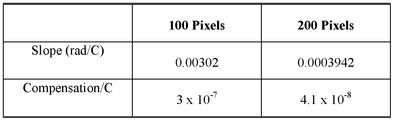
[0037] FIG. 18 shows representative images demonstrating various beam profiles achieved using SCSR-BSI including the original beam (top left), the original beam expanded 2X (bottom left), and the final beam expanded 10X (right). [0038] FIG. 19A and 19B show representative data demonstrating that averaging over 100 (19A) and over 200 (19B) camera pixels improves compensation in SCSR-BSI.
[0039] FIG. 20A and 20B show representative data demonstrating that averaging camera pixels contributes to the improvement or the likeness of S and R fringes and thus the level of compensation. [0040] FIG. 21 shows representative data demonstrating the normalized sum of the differences of the sample and reference channels as a function of how much of the channel is averaged.
[0041] FIG. 22 shows representative data demonstrating the Gaussian fitting results for a single fringe illustrating that increasing the interrogation region, the length of the channel, and/or the camera results in at least two identical interferometers.
[0042] FIG. 23 shows representative data demonstrating the Gaussian fitting results for 24 fringes illustrating that increasing the interrogation region, the length of the channel, and/or the camera results in at least two identical interferometers. [0043] FIG. 24 shows a representative image illustrating a F-126Sx and F-126Hx IDEX fittings that can be used as an inlet guide, sample reservoir and injection port with SCSR-BSI.
[0044] FIG. 25 shows a representative image illustrating that the injection approach can be used for several matrices, including water, PBS, and serum, and does not require a trained user.
[0045] FIG. 26 shows graphs explaining hat averaging over the length of the channel can make the fringes more uniform and more Gaussian and can decrease the amount of high frequency information present in the analog fringe signal.
[0046] FIG. 27 shows BSI can measure free solution interactions on systems that have a large mass differences (e.g., conA and sugar) and that SCSR can works better than the conventional BSI instruments (see error bars) even when used without temperature control.
[0047] FIG. 28 shows results from two experiments performed to measure phase shift due to evaporation at different locations along the channel.
[0048] FIG. 29 shows calculated time until "detectable evaporation."
[0049] Additional advantages of the invention will be set forth in part in the description which follows, and in part will be obvious from the description, or can be learned by practice of the invention. The advantages of the invention will be realized and attained by means of the elements and combinations particularly pointed out in the appended claims. It is to be understood that both the foregoing general description and the following detailed description are exemplary and explanatory only and are not restrictive of the invention, as claimed.
DETAILED DESCRIPTION
[0050] The present invention can be understood more readily by reference to the following detailed description of the invention and the Examples included therein.
[0051] Before the present compounds, compositions, articles, systems, devices, and/or methods are disclosed and described, it is to be understood that they are not limited to specific synthetic methods unless otherwise specified, or to particular reagents unless otherwise specified, as such may, of course, vary. It is also to be understood that the terminology used herein is for the purpose of describing particular aspects only and is not intended to be limiting. Although any methods and materials similar or equivalent to those described herein can be used in the practice or testing of the present invention, example methods and materials are now described.
[0052] All publications mentioned herein are incorporated herein by reference to disclose and describe the methods and/or materials in connection with which the publications are cited. The publications discussed herein are provided solely for their disclosure prior to the filing date of the present application. Nothing herein is to be construed as an admission that the present invention is not entitled to antedate such publication by virtue of prior invention. Further, the dates of publication provided herein can be different from the actual publication dates, which may need to be independently confirmed.
A. DEFINITIONS
[0053] As used in the specification and the appended claims, the singular forms "a," "an" and "the" include plural referents unless the context clearly dictates otherwise. Thus, for example, reference to "a substrate," "a polymer," or "a sample" includes mixtures of two or more such substrates, polymers, or samples, and the like.
[0054] Ranges can be expressed herein as from "about" one particular value, and/or to "about" another particular value. When such a range is expressed, another aspect includes from the one particular value and/or to the other particular value. Similarly, when values are expressed as approximations, by use of the antecedent "about," it will be understood that the particular value forms another aspect. It will be further understood that the endpoints of each of the ranges are significant both in relation to the other endpoint, and independently of the other endpoint. It is also understood that there are a number of values disclosed herein, and that each value is also herein disclosed as "about" that particular value in addition to the value itself. For example, if the value "10" is disclosed, then "about 10" is also disclosed. It is also understood that each unit between two particular units are also disclosed. For example, if 10 and 15 are disclosed, then 11, 12, 13, and 14 are also disclosed.
[0055] As used herein, the terms "optional" or "optionally" means that the subsequently described event or circumstance may or may not occur, and that the description includes instances where the event or circumstance occurs and instances where it does not. [0056] As used herein, the term "polymer" refers to a relatively high molecular weight organic compound, natural or synthetic (e.g., polyethylene, rubber, cellulose), whose structure can be represented by a repeated small unit, the monomer (e.g., ethane, isoprene, β- glucose). Synthetic polymers are typically formed by addition or condensation
polymerization of monomers. [0057] As used herein, the term "copolymer" refers to a polymer formed from two or more different repeating units (monomer residues). By way of example and without limitation, a copolymer can be an alternating copolymer, a random copolymer, a block copolymer, or a graft copolymer.
[0058] As used herein, the term "bioassay" refers to a procedure for determining the concentration, purity, and/or biological activity of a substance.
[0059] As used herein, the term "chemical event" refers to a change in a physical or chemical property of an analyte in a sample that can be detected by the disclosed systems and methods. For example, a change in refractive index (RI), solute concentration and/or temperature can be a chemical event. As a further example, a biochemical binding or association (e.g., DNA hybridization) between two chemical or biological species can be a chemical event. As a further example, a disassociation of a complex or molecule can also be detected as an RI change. As a further example, a change in temperature, concentration, and
association/dissociation can be observed as a function of time. As a further example, bioassays can be performed and can be used to observe a chemical event. [0060] Disclosed are the components to be used to prepare the compositions of the invention as well as the compositions themselves to be used within the methods disclosed herein.
These and other materials are disclosed herein, and it is understood that when combinations, subsets, interactions, groups, etc. of these materials are disclosed that while specific reference of each various individual and collective combinations and permutation of these compounds may not be explicitly disclosed, each is specifically contemplated and described herein. For example, if a particular compound is disclosed and discussed and a number of modifications that can be made to a number of molecules including the compounds are discussed, specifically contemplated is each and every combination and permutation of the compound and the modifications that are possible unless specifically indicated to the contrary. Thus, if a class of molecules A, B, and C are disclosed as well as a class of molecules D, E, and F and an example of a combination molecule, A-D is disclosed, then even if each is not individually recited each is individually and collectively contemplated meaning combinations, A-E, A-F, B-D, B-E, B-F, C-D, C-E, and C-F are considered disclosed. Likewise, any subset or combination of these is also disclosed. Thus, for example, the sub-group of A-E, B-F, and C- E would be considered disclosed. This concept applies to all aspects of this application including, but not limited to, steps in methods of making and using the compositions of the invention. Thus, if there are a variety of additional steps that can be performed it is understood that each of these additional steps can be performed with any specific aspect or combination of aspects of the methods of the invention.
[0061] It is understood that the compositions disclosed herein have certain functions.
Disclosed herein are certain structural requirements for performing the disclosed functions, and it is understood that there are a variety of structures that can perform the same function that are related to the disclosed structures, and that these structures will typically achieve the same result.
B. SINGLE CHANNEL SAMPLE REFERENCE INTERFEROMETRIC SYSTEMS
[0062] In one aspect, the invention relates to an interferometric detection system comprising:
(a) a channel formed in a substrate, wherein the channel has a longitudinal direction and a transverse direction, and wherein the channel is configured for reception of a liquid sample;
(b) a light source for generating a light beam, wherein the light beam is elongated in the longitudinal direction of the channel, and wherein the light source is positioned to direct the light beam onto the substrate such that the light beam is incident on at least a portion of the channel greater than 4 mm in length, such that, during operation, scattered light is generated through reflective and refractive interaction of the light beam with a substrate/channel interface and the sample, the scattered light comprising interference fringe patterns elongated in at least one direction, wherein the interference fringe patterns shift in response to changes in the refractive index of the sample; and (c) a photodetector for simultaneously receiving the scattered light and generating a plurality of intensity signals.
[0063] In one aspect, the invention relates to an interferometric detection system comprising: (a) a channel formed in a substrate, wherein the channel has a longitudinal direction and a transverse direction, and wherein the channel is configured for reception of two or more liquid samples by having at least two inlets positioned at opposing locations of the channel, and at least one outlet positioned at a point between the at least two inlets, thereby defining a right side of the channel and a left side of the channel; (b) a light source for generating a light beam, wherein the light beam is elongated in the longitudinal direction of the channel, and wherein the light source is positioned to direct the light beam onto the substrate such that the light beam is simultaneously incident on at least a portion of the right side of the channel and at least a portion of the left side of the channel, such that, during operation, scattered light is generated through reflective and refractive interaction of the light beam with a
substrate/channel interface and the two or more samples, the scattered light comprising interference fringe patterns elongated in at least one direction, wherein the interference fringe patterns shift in response to changes in the refractive index of the two or more samples; and (c) a photodetector for simultaneously receiving the scattered light and generating a plurality of intensity signals.
[0064] In one aspect, the invention relates to an interferometric detection system comprising: (a) a channel formed in a substrate, wherein the channel has a longitudinal direction and a transverse direction, and wherein the channel is configured for reception of a liquid sample; (b) a light source for generating a light beam, wherein the light beam is elongated in the longitudinal direction of the channel, and wherein the light source is positioned to direct the light beam onto the substrate such that the light beam is incident on at least a portion of the channel greater, such that, during operation, scattered light is generated through reflective and refractive interaction of the light beam with a substrate/channel interface and the sample, the scattered light comprising interference fringe patterns elongated in at least one direction, wherein the interference fringe patterns shift in response to changes in the refractive index of the sample; and (c) a photodetector for simultaneously receiving the scattered light and generating a plurality of intensity signals, wherein the photodetector is positioned less than 40 cm from the channel during operation. [0065] In one aspect, the invention relates to an interferometric detection system comprising: (a) a channel formed in a substrate, wherein the channel has a longitudinal direction and a transverse direction, and wherein the channel is configured for reception of two or more liquid samples by having at least two inlets positioned at opposing locations of the channel, and at least one outlet positioned at a point between the at least two inlets, thereby defining a right side of the channel and a left side of the channel; (b) a light source for generating a light beam, wherein the light beam is elongated in the longitudinal direction of the channel, and wherein the light source is positioned to direct the light beam onto the substrate such that the light beam is incident on at least a portion of the channel greater than 4 mm in length along the longitudinal direction and is simultaneously incident on at least a portion of the right side of the channel and at least a portion of the left side of the channel, such that, during operation, scattered light is generated through reflective and refractive interaction of the light beam with a substrate/channel interface and the two or more samples, the scattered light comprising interference fringe patterns elongated in at least one direction, wherein the interference fringe patterns shift in response to changes in the refractive index of the two or more samples; (c) a closure element adapted to close the inlet, thereby reducing evaporation of liquid positioned within the channel and/or inlet; and (d) a photodetector for
simultaneously receiving the scattered light and generating a plurality of intensity signals, wherein the photodetector is positioned less than 40 cm from the channel during operation.
[0066] An exemplary interferometric detection apparatus is illustrated in FIG. 1, wherein a light beam from a HeNe laser passes through beam conditioning optics (i.e., an optical element) to increase the width of the beam. Multiple regions (e.g., sample and reference) of a channel, as illustrated in FIG. 2, positioned on a temperature controlled chip can then be impinged with the spread light beam, creating backscattered light and elongated interference fringes that are directed to a s-D CCD array detector. A signal analyzer (i.e., computer) can then be used to interpret the signal intensity information from the detector and correlate the same to a change in the refractive index of the portion of the sample from the interrogated regions of the channel.
[0067] In another aspect, any element in a SCSR interferometric detection system or apparatus can comprise a single component or multiple components. In various aspects, multiple lasers can be utilized to produce separate light beams, wherein each light beam impinges a different portion of the channel. In another aspect, multiple optical elements can be utilized, either on a single light beam or multiple light beams. In another aspect, multiple detectors and/or signal analyzers can be present.
[0068] In a further aspect, the system further comprises at least one signal analyzer for receiving the intensity signals and determining therefrom one or more characteristic properties of the sample. [0069] In a further aspect, the system further comprises a plurality of reservoirs, wherein each of the plurality of reservoirs is in fluid communication with one of the at least two inlets. In a still further aspect, the two or more samples comprise a first sample and a second sample. In yet a further aspect, the first sample is a sample to be analyzed, and the second sample is a reference. In an even further aspect, at least one of the two or more samples comprises a reference. [0070] In a further aspect, the substrate and channel together comprise a capillary tube.
[0071] In a further aspect, the scattered light is backscattered light. In a still further aspect, the scattered light comprises backscattered light.
[0072] In a still further aspect, the invention relates to devices and methods wherein interferometric interrogation of a sample solution and interferometric interrogation a reference solution are performed simultaneously and performed within the same channel or within two channels in environmental communication (i.e., sharing the sample environment, including, for example, pressure and temperature) with the same light source. In one aspect, this can be accomplished by a single laser than has been elongated in the longitudinal direction of the channel. 1. CHANNEL
[0073] In one aspect, the interferometric detection systems of the present invention comprise a channel formed in a substrate, wherein the channel has a longitudinal direction and a transverse direction, and wherein the channel is configured for reception of a liquid sample. In one aspect, the interferometric detection systems of the present invention comprise a channel formed in a substrate, wherein the channel has a longitudinal direction and a transverse direction, and wherein the channel is configured for reception of two or more liquid samples by having at least two inlets positioned at opposing locations of the channel, and at least one outlet positioned at a point between the at least two inlets, thereby defining a right side of the channel and a left side of the channel. The channel of the present invention can, in various aspects, be formed from a substrate such as a piece of silica or other suitable optically transmissive material. In various aspects, the material of composition of the substrate has a different index of refraction than that of the sample to be analyzed. In a further aspect, as refractive index can vary significantly with temperature, the substrate can optionally be mounted and/or connected to a temperature control device. In a still further aspect, the substrate can be tilted, for example, about 7°, such that scattered light from channel can be directed to a detector.
[0074] In a further aspect, the channel has a generally semi-circular cross-sectional shape. A unique multi-pass optical configuration is inherently created by the channel characteristics, and is based on the interaction of the unfocused laser beam and the curved surface of the channel that allows interferometric measurements in small volumes at high sensitivity.
Alternatively, the channel can have a substantially circular or generally rectangular cross- sectional shape. In a still further aspect, the substrate and channel together comprise a capillary tube. In yet a further aspect, the substrate and channel together comprise a microfluidic device, for example, a silica substrate, or a polymeric substrate [e.g., polydimethylsiloxane (PDMS) or polymethyl methacrylate (PMMA)], and an etched channel formed in the substrate for reception of a sample, the channel having a cross sectional shape. In an even further aspect, the cross sectional shape of a channel is semi-circular. In a still further aspect, the cross sectional shape of a channel is square, rectangular, or elliptical. In yet a further aspect, the cross sectional shape of a channel can comprise any shape suitable for use in a BSI technique. In an even further aspect, a substrate can comprise one or multiple channels of the same or varying dimensions. In various aspects, the channel can have a radius of from about 5 to about 250 micrometers, for example, about 5, 10, 20, 30, 40, 50, 75, 100, 150, 200, or 250 micrometers. In still other aspects, the channel can have a radius of up to about 1 millimeter or larger, such as, for example, 0.5 millimeters, 0.75 millimeters, 1 millimeter, 1.25 millimeters, 1.5 millimeters, 1.75 millimeters, 2 millimeters, or more.
[0075] A microfluidic channel, if present, can hold and/or transport the same or varying samples, and a mixing zone. The design of a mixing zone can allow at least initial mixing of, for example, one or more binding pair species. The at least initially mixed sample can then be subjected to a stop-flow analysis, provided that the reaction and/or interaction between the binding pair species continues or is not complete at the time of analysis. The specific design of a microfluidic channel, mixing zone, and the conditions of mixing can vary, depending on such factors as, for example, the concentration, response, and volume of a sample and/or species. [0076] In a further aspect, a channel can be divided into multiple discrete zones along the length of the channel. In a still further aspect, a channel comprises at least two discrete zones. In yet a further aspect, a channel can comprise 2, 3, 4, 5, 6, 7, 8, 9, 10, or more zones. Any individual zone can have dimensions, such as, for example, length, the same as or different from any other zones along the same channel. In an even further aspect, at least two zones have the same length. In a still further aspect, all of the zones along a channel have the same or substantially the same length. In yet a further aspect, each zone can have a length along the channel of from about 1 to about 1 ,000 micrometers, for example, about 1, 2, 3, 5, 8, 10, 20, 40, 80, 100, 200, 400, 800, or 1,000 micrometers. In an even further aspect, each zone can have a length of less than about 1 micrometer or greater than about 1 ,000 micrometer, and the present disclosure is not intended to be limited to any particular zone dimension. Further, any individual zone can be in contact with or separated from an adjacent zone. In a still further aspect, at least one zone is in contact with an adj acent zone. In yet a further aspect, each of the zones along a channel is in contact such that there are no breaks between individual zones. In an even further aspect, at least one zone is separated from an adj acent zone by a portion of the capillary not in a zone. In a still further aspect, each of the zones along a channel is separated from each other such that no zones are in direct contact with another. In yet a further aspect, at least one zone can be used as a reference and/or experimental control. In an even further aspect, each measurement zone can be positioned adjacent to a reference zone, such that the channel comprises alternating measurement and reference zones. It should be noted that the zones along a channel do not need to be specifically marked or delineated, only that the system be capable of addressing and detecting scattered light from each zone.
[0077] In a further aspect, a first discrete zone is disposed between a first inlet and the at least one outlet, and wherein a second discrete zone is disposed between a second inlet and the at least one outlet.
[0078] In a further aspect, any one or more zones in a channel can be separated from any other zones by a junction, such as, for example, a union, coupling, tee, injection port, mixing port, or a combination thereof. For example, one or more zones in the flow path of a sample can be positioned upstream of an inj ection port where, for example, an analyte can be introduced. In such an aspect, one or more zones can also be positioned downstream of the injection port. [0079] In a further aspect, a channel can be divided into two, three, or more regions, wherein each region is separated from other regions by an outlet. In a still further aspect, an outlet can prevent a fluid in one region of a channel from contacting and/or mixing with a fluid from another region of the channel. In yet a further aspect, any combination of regions or all of the regions can be positioned such that they will be impinged with at least a portion of the light beam. In such an aspect, multiple regions of a single channel can be used to conduct multiple analyses of the same or different type in a single instrumental setup. In an even further aspect, a channel has two regions, wherein an outlet is positioned in the channel between the two regions, and wherein each of the regions are at least partially in an area of the channel where the light beam is incident.
[0080] In a further aspect, if multiple regions are present, each region can have an input and an output port. An exemplary schematic of a channel comprising two regions, wherein each region has an input and an output port is illustrated in FIG. 7. In a still further aspect, the input and/or output ports can be configured so as not to interfere with the generation of scattered light, such as, for example, backscattered light, and the resulting measurements. It should be noted that other geometric designs and configurations can be utilized, and the present invention is not intended to be limited to the specific exemplary configurations disclosed herein. Thus, in one aspect, a single channel can allow for analysis of multiple samples simultaneously in the same physical environment. [0081] As illustrated in Fig. 13, a hydrophobic coating can be optionally used to stop capillary action of solution within the channel. Fig. 13 shows a photograph of Sigmacoat serving as a hydrophobic coating, to stop the capillary action and inhibit the sample and reference from meeting in the center of the channel where they would mix. The liquid has stopped at this coated region, as capillary action is arrested. This demonstrates that a hydrophobic coating can be used to create a gap in the center of the channel, so that the sample and reference solutions can be introduced and separated within the SCSR detection beam interrogating region.
[0082] As depicted in Fig. 5 and Fig. 6, the inlets can be positioned at opposing locations (e.g., opposing ends) of the channel. Opposing locations can be, for example, located at the ends of the channel, with an outlet positioned between the inlets. It is appreciated, however, that the inlets are not required to be at the ends of the channel, as long as the configuration of inlets and outlets allows for SCSR interrogation as described herein.
2. LIGHT SOURCE
[0083] In one aspect, the interferometric systems of the present invention comprise a light source for generating a light beam, wherein the light beam is elongated in the longitudinal direction of the channel, and wherein the light source is positioned to direct the light beam onto the substrate such that the light beam is incident on at least a portion of the channel greater than 4 mm in length, such that, during operation, scattered light is generated through reflective and refractive interaction of the light beam with a substrate/channel interface and the sample, the scattered light comprising interference fringe patterns elongated in at least one direction, wherein the interference fringe patterns shift in response to changes in the refractive index of the sample.
[0084] In one aspect, the interferometric systems of the present invention comprise a light source for generating a light beam, wherein the light beam is elongated in the longitudinal direction of the channel, and wherein the light source is positioned to direct the light beam onto the substrate such that the light beam is simultaneously incident on at least a portion of the right side of the channel and at least a portion of the left side of the channel, such that, during operation, scattered light is generated through reflective and refractive interaction of the light beam with a substrate/channel interface and the two or more samples, the scattered light comprising interference fringe patterns elongated in at least one direction, wherein the interference fringe patterns shift in response to changes in the refractive index of the two or more samples.
[0085] In various aspects, the light source generates an easy to align optical beam that is incident on the etched channel for generating scattered light. In a further aspect, the light source generates an optical beam that is collimated, such as, for example, the light emitted from a HeNe laser. In a still further aspect, the light source generates an optical beam that is not well collimated and disperses in, for example, a Gaussian profile, such as that generated by a diode laser.
[0086] Typically, two types of lasers can be employed. In various aspects, one laser (the diode) creates a laser beam that is elongated in the longitudinal direction of the channel. In further aspects, the other (HeNe) creates a laser beam that is not elongated longitudinally along the length of the channel, but can be later elongated longitudinally along the length of the channel by beam-stretching optics. These methods can both achieve the same end of an elongated beam impinging upon the channel, but do so through different means. It can be noted that, in certain aspects, when the diameter of the laser beam is the same as the thickness of the glass chip, new interference phenomena can arise. This can be avoided by selecting the width of the beam to be smaller than the thickness of the glass chip (0.8mm width laser and 1.7mm thickness glass chip).
[0087] In a further aspect, a single light beam is incident upon the substrate. [0088] In a further aspect, the light beam has a substantially uniform intensity profile across at least a portion of the plurality of discrete zones. In a yet further aspect, the light beam has a substantially Gaussian intensity profile in the axis perpendicular to the zones. In a still further aspect, the portion of the light beam impinging the channel has an elongated intensity profile. [0089] In various aspects, the light beam is incident on at least a portion of the channel greater than 4 mm in length along the longitudinal direction. In a further aspect, the light beam is incident on at least a portion of the channel greater than 5 mm of length of the channel in the longitudinal direction. In a still further aspect, the light beam is incident on at least a portion of the channel greater than 6 mm of length of the channel in the longitudinal direction. In yet a further aspect, the light beam is incident on at least a portion of the channel greater than 7 mm of length of the channel in the longitudinal direction. In an even further aspect, the light beam is incident on at least a portion of the channel greater than 8 mm of length of the channel in the longitudinal direction. In a still further aspect, the light beam is incident on at least a portion of the channel greater than 9 mm of length of the channel in the longitudinal direction. In yet a further aspect, the light beam is incident on at least a portion of the channel greater than 10 mm, 12 mm, 14 mm, 16 mm, 18 mm, or 20 mm of length of the channel in the longitudinal direction.
[0090] In a further aspect, at least a portion of the light beam incident on the channel covers at least two discrete zones. In a still further aspect, at least a portion of the light beam is incident on the channel such that the intensity of the light on each of at least two zones is the same or substantially the same. In yet a further aspect, at least a portion of the light beam is incident on the channel such that the each of the zones along the channel receive the same or substantially the same intensity of light. For example, a light beam having a Gaussian intensity profile can be incident on a channel such that at least two zones along the channel are within the peak of the intensity profile, receiving the same or substantially the same intensity of light. In an even further aspect, the portion of the light beam incident on the channel can have a non-Gaussian profile, such as, for example, a plateau (e.g., top-hat). The portion of the light beam in the wings of the Gaussian intensity profile can be incident upon other portions of the channel or can be directed elsewhere.
[0091] In a further aspect, variations in light intensity across zones of interest can result in measurement errors. In a still further aspect, if portions of a light beam having varying intensity are incident upon multiple zones of a channel, a calibration can be performed wherein the expected intensity of light, resulting interaction, and scattering is determined for correlation of future measurements.
[0092] The light source can comprise any suitable equipment and/or means for generating light, provided that the frequency and intensity of the generated light are sufficient to interact with a sample and/or a marker compound and provide elongated fringe patterns as described herein. Light sources, such as HeNe lasers and diode lasers, are commercially available and one of skill in the art could readily select an appropriate light source for use with the systems and methods of the present invention. [0093] In a further aspect, a light source can comprise a single laser. In a still further aspect, a light source can comprise two or more lasers, each generating a beam that can impinge one or more zones of a channel. In yet a further aspect, if two or more lasers are present, any individual laser can be the same as or different from any other laser. For example, two individual lasers can be utilized, each producing a light beam having different properties, such as, for example, wavelength, such that different interactions can be determined in each zone along a channel.
[0094] As with any interferometric technique for micro-chemical analysis, it can be advantageous, in various aspects, for the light source to have monochromaticity and a high photon flux. If warranted, the intensity of a light source, such as a laser, can be reduced using neutral density filters. [0095] In a further aspect, the system further comprises an optical element positioned between the light source and the channel, wherein the optical element is capable of at least one of spreading, splitting, rastering, or a combination thereof the light beam in a direction parallel to the length of the channel. In various aspects, such an optical element can facilitate contact of the light beam with two or more zones along a channel. In a further aspect, a light source, such as a diode laser, generates a light beam having a Gaussian profile, and an optical element is not necessary or present. In a still further aspect, a light source, such as a HeNe laser, generates a collimated light beam and an optical element can be present to spread the light beam and facilitate contact of the light beam with at least two zones along the channel. Such a light beam configuration can allow for multiple measurements or sample and reference measurements to be made simultaneously or substantially simultaneously within the same channel.
[0096] In a further aspect, the optical element is capable of spreading the light beam in a direction parallel to the length of the channel. In a still further aspect, the optical element comprises a cylindrical lens. In yet a further aspect, the optical element comprises an anamorphic lens.
[0097] In a further aspect, an optical element can comprise a dispersing element capable of dispersing the light beam in at least one direction. Such an element can be useful to disperse a well collimated light beam in a direction parallel to the longitudinal axis of a channel, such that when incident upon the channel, the light beam contacts at least two zones. In such an aspect, the optical element, if present, can comprise a cylindrical lens, such as, for example, a 50.8 mm by 19 mm cylindrical lens with an effective focal length of 25.4 cm, to produce a beam 0.8 mm by 4.0 mm. A cylindrical lens can thus be used to disperse the light beam from a HeNe laser to a line. An amorphic lens can also be used. [0098] In a further aspect, an optical element can comprise a beam splitting element capable of splitting a well collimated light beam into two or more individual beams, each of which can be incident upon a separate zone on the same channel.
[0099] In a further aspect, an optical element can comprise a rastering element capable of rastering a light beam across two or more zones of a channel. If such a rastering element is present, the speed at which the beam is rastered across the two or more zones should be sufficiently fast to prevent measurement errors from occurring due to temperature changes and/or changes in sample composition flowing through a capillary channel.
[00100] In a further aspect, two or more optical elements of the same or varying type can be utilized. In a still further aspect, additional beam conditioning optics can be utilized in addition to, for example, a dispersing cylindrical lens. In yet a further aspect, other types of optical elements capable of facilitating contact of the light beam with at least two zones along the channel are contemplated, and the present disclosure is not intended to be limited to the particular optical elements recited herein. In an even further aspect, an optical element, such as, for example, a lens, can be positioned in the optical path between the light source and the channel. In a still further aspect, an optical element, such as, for example, a rastering element, can be attached to or integral with the light source.
[00101] In a further aspect, one or more additional optical components can be present, such as, for example, a mirror, a neutral density filter, or a combination thereof, so as to direct the light beam and/or the scattered light in a desired direction or to adjust one or more properties of a light beam.
3. CLOSURE ELEMENT
[00102] In one aspect, the interferometric systems of the present invention comprise a closure element adapted to close the inlet, thereby reducing evaporation of liquid positioned within the channel and/or inlet. In a further aspect, the interferometric systems of the present invention may comprise multiple closure elements. Examples of closure elements include, but are not limited to, caps, corks, ferrules, stoppers, collets, and tops.
[00103] While it is not strictly necessary that the one or more inlets be completely sealed by the closure element, it can be preferred that the closure element, when in use, reduces, minimizes, or eliminates exposure of the sample to the environment. [00104] The distance from the chip surface to the closure element may be optimized for volume minimization, ease of production, and injection consistency. A smaller volume, dimension, and surface area exposed to the environment minimize the evaporation of solvents and solutions. This is because 1) the sample it always contained within the dispensing object (pipette), 2) only a small area of the sample / reference solution surface is exposed to the environment (i.e., the exposed surface area is defined by the inner diameter of the receptacle which is very small), and 3) the sample detection zone cannot communicate with the atmosphere due to the fact that it is spatially separated from the top of the receptacle (where evaporation can occur) and after the injection is performed, a valve to the waste tube connected to the exit hole is closed, thereby reducing, minimizing, or eliminating environmental communication. With the detection zone residing several centimeters from the introduction site, the time for evaporative communication is much longer (e.g., minutes) than needed to perform the data collection. Thus, without wishing to be bound by theory, the SCSR method may allow for a user to place a drop from a standard pipette, have the low- mi croliter volume sample be automatically and passively (no pump) introduced into the detection region, and be at the same pressure as the reference fluid.
[00105] It is appreciated that reduction or elimination of evaporation can also be accomplished by locating the interrogation region a sufficient distance from an inlet. For example, the outer edge of the interrogation region can be positioned at least 2 mm, at least 3 mm, at least 4 mm, at least 5 mm, at least 6 mm, at least 7 mm, at least 8 mm, at least 9 mm, at least 10 mm, at least 11 mm, at least 12 mm, at least 13 mm, at least 14 mm, at least 15 mm, at least 16 mm, at least 17 mm, at least 18 mm, at least 19 mm, at least 20 mm, at least 25 mm, at least 30 mm, at least 40 mm, at least 50 mm from an inlet. In one aspect, the distance can be measured along the horizontal length of the channel between the inlet and an edge of the interrogation region. In a further aspect, the distance can be measured along the horizontal length of the channel between the inlet and an edge of the interrogation region as well as the vertical distance of the inlet itself. It is understood that this aspect can be used in combination with one or more closure elements.
4. PHOTODETECTOR
[00106] In one aspect, the interferometric systems of the present invention comprise a photodetector for simultaneously receiving the scattered light and generating a plurality of intensity signals.
[00107] In one aspect, the interferometric systems of the present invention comprise a photodetector for simultaneously receiving the scattered light and generating a plurality of intensity signals, wherein the photodetector is positioned less than 40 cm from the channel during operation. [00108] A photodetector detects the scattered light and converts it into intensity signals that vary as the positions of the light bands in the elongated fringe patterns shift, and can thus be employed to determine the refractive index (RI), or an RI related characteristic property, of the sample. Exemplary properties that can be detected and/or quantified using the inventive techniques can comprise, without limitation, changes in mass, concentration, conformation, structure, charge level, level of hydration, or a combination thereof. In other aspects, the progress of one or more chemical reactions can be monitored, such as, for example, that can occur in an aqueous or a non-aqueous solvent.
[00109] The photodetector can, in various aspects, comprise any suitable image sensing device, such as, for example, a bi-cell sensor, a linear or area array CCD or CMOS camera and laser beam analyzer assembly, a photodetector assembly, an avalanche photodiode, or other suitable photodetection device. In a further aspect, the photodetector is an array photodetector capable of detecting multiple elongated interference fringe patterns. In a still further aspect, a photodetector can comprise multiple individual photodetectors to detect the elongated interference fringe patterns produced by the interaction of the light beam with the sample, channel wall, and optional marker compounds. The scattered light incident upon the photodetector comprises elongated interference fringe patterns that correspond to the discrete zones along the length of the channel. These elongated interference fringe patterns include a plurality of light bands whose positions shift as the refractive index of that portion of the sample is varied, either through compositional changes, temperature changes, or a combination thereof. The specific position of the photodetector can vary depending upon the arrangement of other elements. In yet a further aspect, the photodetector can be positioned at an approximately 45° angle to the channel.
[00110] The intensity signals from the photodetector can then be directed to a signal analyzer for fringe pattern analysis and determination of the RI or RI related characteristic property of the sample and/or reference in each zone of the channel. The signal analyzer can be a computer or a dedicated electrical circuit. In various aspects, the signal analyzer includes the programming or circuitry necessary to determine from the intensity signals, the RI or other characteristic property of the sample in each discrete zone of interest. In a further aspect, the signal analyzer is capable of detecting positional shifts in interference fringe patterns and correlating those positional shifts with a change in the refractive index of at least a portion of the sample. In a still further aspect, the signal analyzer is capable of detecting positional shifts in interference fringe patterns and correlating those positional shifts with a change in the refractive index occurring in the zones of the channel. In yet a further aspect, the signal analyzer is capable of comparing data received from a photodetector and determining the refractive index and/or a characteristic property of the sample in any two or more zones of the channel.
[00111] In a further aspect, the signal analyzer is capable of interpreting an intensity signal received from a photodetector and determining one or more characteristic properties of the sample in each of the zones of the channel. In a still further aspect, the signal analyzer can utilize a mathematical algorithm to interpret positional shifts in the interference fringe patterns incident on a photodetector. In yet a further aspect, known mathematical algorithms and/or signal analysis software, such as, for example, deconvolution algorithms, can be utilized to interpret positional shifts occurring from a multiplexed scattering interferometric analysis.
[00112] The photodetector can be employed for any application that requires interferometric measurements; however, the photodetector can be particularly useful for making universal solute quantification, temperature, and flow rate measurements. In these applications, the photodetector provides ultra-high sensitivity due to the multi-pass optical configuration of the channel. In the temperature measuring aspect, a signal analyzer receives the signals generated by the photodetector and analyzes them using the principle that the refractive index of the sample varies proportionally to its temperature. In this manner, the signal analyzer can calculate temperature changes in the sample from positional shifts in the detected interference fringe patterns. In a further aspect, the ability to detect elongated interference fringe patterns from interactions occurring in two or more zones along a channel can provide real-time reference and/or comparative measurements without the problem of changing conditions between measurements. In a still further aspect, a signal analyzer, such as a computer or an electrical circuit, can thus be employed to analyze the photodetector signals, and determine the characteristic property of the sample.
[00113] In the flow measuring aspect, the same principle is also employed by the signal analyzer to identify a point in time at which perturbation is detected in a flow stream in the channel. In the case of a thermal perturbation, a flow stream whose flow rate is to be determined, is locally heated at a point that is a known distance along the channel from the detection zone. The signal analyzer for this aspect includes a timing means or circuit that notes the time at which the flow stream heating occurs. Then, the signal analyzer determines from the positional shifts of the light bands in the interference fringe patterns, the time at which thermal perturbation in the flow stream arrives at the detection zone. The signal analyzer can then determine the flow rate from the time interval and distance values. Other perturbations to the flow stream, include, but are not limited to, introduction into the stream of small physical objects, such as glass microbeads or nanoparticles. Heating of gold particles in response to a chemical reaction or by the change in absorption of light due to surface-bound solutes or the capture of targets contained within the solution can be used to enhance the temperature induced RI perturbation and thus to interrogate the composition of the sample. In a further aspect, measurements at multiple zones along the channel can be used to determine temperature gradients or rate of temperature change of a sample within the channel.
[00114] In a further aspect, the systems and methods of the present invention can be used to obtain multiple measurements simultaneously or substantially simultaneously from discrete zones along the length of a channel. In such an aspect, each zone can provide a unique measurement and/or reference. In a further aspect, temporal detection can be used to measure changes in a sample over time as the sample flows through the channel, for example, with a flow injection analysis system. [00115] In a further aspect, the sample is a fluid, for example a gas, a liquid, or a supercritical fluid. In a still further aspect, the sample is a liquid, which can be a
substantially pure liquid, a solution, or a mixture (e.g., biological fluids, cellular fluids). In a still further aspect, the sample can further comprise one or more analytes. In yet a further aspect, a sample can be introduced into the channel via an injection port at, for example, one end of the channel.
[00116] As the light beam impinges one or more discrete regions of a channel, the resulting elongated interference fringe patterns can move with a change in refractive index. The ability to analyze multiple discrete zones simultaneously can provide high spatial resolution and can provide measurement techniques with an integrated reference. [00117] In a further aspect, the photodetector is capable of spatially resolving scattered light incident on a surface thereof. In a still further aspect, the photodetector comprises a three dimensional array.
[00118] In various aspects, the photodetector resolution, including pixel size, spacing, and photon flux sensitivity, can be selected based upon certain specifications. Thus, in various aspects, between about 50 camera pixels and 400 camera pixels can be interrogated. In a further aspect, between about 50 camera pixels and 350 camera pixels can be interrogated. In a still further aspect, between about 50 camera pixels and 300 camera pixels can be interrogated. In yet a further aspect, between about 50 camera pixels and 250 camera pixels can be interrogated. In an even further aspect, between about 50 camera pixels and 200 camera pixels can be interrogated. In a still further aspect, between about 50 camera pixels and 150 camera pixels can be interrogated.
C. MiCROFLuiDic DEVICES
[00119] In one aspect, the invention relates to a microfluidic device comprising: (a) a substrate having a channel formed therein, wherein the channel has at least one inlet; (b) a closure element adapted to close the inlet, thereby reducing evaporation of liquid positioned within the channel and/or inlet.
[00120] In a further aspect, closing is via friction fit. In a still further aspect, closing is via screw fit. [00121] In a further aspect, the device further comprises a reservoir positioned between the inlet and the channel. In a still further aspect, the device further comprises an interferometric detection system.
[00122] In a further aspect, the substrate and channel together comprise a capillary tube. D. ANALYTICAL METHODS
[00123] Conventional backscattering interferometry, as illustrated in FIG. 1, utilizes interference fringes generated by backscattered light to detect refractive index changes in a sample. The backscatter detection technique is generally disclosed in U.S. Pat. No. 5,325,170 to Bornhop, and U.S. Patent Publication No. US2009/0103091 to Bornhop, both of which are hereby incorporated by reference. With reference to FIG. 1, a conventional backscattering interferometric detection system 10 comprises a laser 12 that produces a light beam 14. The light beam can be directed through one or more neutral density filters 16 to reduce the intensity of the light beam, before being reflected on a mirror 18 and directed to impinge an etched channel 22 on a chip 20. The chip can also be positioned on a temperature controlled support block 23 and/or an X-Y translation stage 24. After various reflective and refractive interactions with the channel and sample, the scattered light can be directed to a detector 25, and the intensity signals generated by the detector interpreted by a computer based signal analyzer 28.
[00124] In the single channel sample reference (SCSR) configuration (FIG. 3), a collimated laser beam is expanded, for example, to approximately 8-10 mm, in the axis along the channel, while maintaining the Gaussian shape in the axis perpendicular to the channel. When this beam is impinged onto the microfluidic channel, at least two samples can be interrogated in the channel simultaneously. By separating the samples with either an air gap, a droplet of immiscible material, or other gap or hole in the channel, the samples may be probed in the same channel simultaneously, with the same laser. Thus, the sample and the reference may be interrogated in the same interferometer.
[00125] Rapid monitoring and detection of ultra small volume samples is in great demand. One analytical approach, Back-Scattering Interferometry (BSI), derives from the observation that coherent light impinging on a cylindrically shaped capillary produces a highly modulated interference pattern. Typically, BSI analyzes reflections from a capillary tube filled with a liquid of which one wants to measure the refractive index. The technique has been shown capable of measuring changes in refractive index of liquids on the order of 10"9. The BSI technique is a simple and universal method of detecting refractive index changes in small volumes of liquid and can be applied to monitor changes in concentrations of solutes, flow rates, and temperature, all conducted in nanoliter volumes.
[00126] The BSI technique is based on interference of laser light after it is reflected from different regions in a capillary or like sample container. Suitable methods and apparatus are described in U.S. Pat. No. 5,325,170 and WO-A-01/14858, which are hereby incorporated by reference. The reflected or back scattered light is viewed across a range of angles with respect to the laser light path. The reflections generate an interference pattern that moves in relation to such angles upon changing refractive index of the sample. The small angle interference partem traditionally considered has a repetition frequency in the refractive index space that limits the ability to measure refractive index to refractive index changes causing one such repetition. In one aspect, such refractive index changes are typically on the order of three decades. In another aspect, such changes are on the order of many decades. In another aspect, the fringes can move over many decades up to, for example, the point where the refractive index of the fluid and the channel are matched.
[00127] BSI methods direct a coherent light beam along a light path to impinge on a first light transmissive material and pass there through, to pass through a sample which is to be the subject of the measurement, and to impinge on a further light transmissive material, the sample being located between the first and further materials, detecting reflected light over a range of angles with respect to the light path, the reflected light including reflections from interfaces between different substances including interfaces between the first material and the sample and between the sample and the further material which interfere to produce an interference pattern comprising alternating lighter and darker fringes spatially separated according to their angular position with respect to the light path, and conducting an analysis of the interference partem to determine there from the refractive index, wherein the analysis comprises observation of a parameter of the interference pattern which is quantitatively related to sample refractive index dependent variations in the intensity of reflections of light which has passed through the sample.
[00128] The analysis comprises one or both of: (a) the observation of the angle with respect to the light path at which there is an abrupt change in the intensity of the lighter fringes, or (b) the observation of the position of these fringes of a low frequency component of the variation of intensity between the lighter and darker fringes. The first of these (a), relies upon the dependency of the angle at which total internal reflection occurs at an interface between the sample and the further material on the refractive index of the sample. The second (b), relies upon the dependency of the intensity of reflections from that interface on the refractive index as given by the Fresnel coefficients. The rectangular chips, due to corners of the cross section, can also have an additional single component in the diffraction pattern. [00129] The first material and the further material are usually composed of the same substance and may be opposite side walls of a container within which the sample is held or conducted. For instance, the sample may be contained in, e.g. flowed through, a capillary dimensioned flow channel such as a capillary tube. The side wall of the capillary tube nearer the light source is then the "first material" and the opposite side wall is the "further material." The cross-sectional depth of the channel is limited only by the coherence length of the light and its breadth is limited only by the width of the light beam. Preferably, the depth of the channel is from 1 to 10 μιτι, but it may be from 1 to 20 μιτι or up to 50 μιτι or more, e.g. up to 1 mm or more. However, sizes of up to 5 mm or 10 mm or more are possible. Suitably, the breadth of the channel is from 0.5 to 2 times its depth, e.g., equal to its depth.
[00130] Typically, at least one the interfaces involving the sample at which light is reflected is curved in a plane containing the light path, the curved interface being convex in the direction facing the incoming light if it is the interface between the first material and the sample and being concave in the direction facing the incoming light if it is the interface between the sample and the further material. The sample is typically a liquid, and can be flowing or stationary. However, the sample can also be a solid or a gas in various aspects of the present invention. The first and/or further materials will normally be solid but in principle can be liquid, e.g., can be formed by a sheathing flow of guidance liquid(s) in a microfluidic device, with the sample being sheathed flow of liquid between such guidance flows. The sample may also be contained in a flow channel of appropriate dimensions in substrate such as a microfluidic chip. The method may therefore be employed to obtain a read out of the result of a reaction conducted on a "lab on a chip" type of device.
[00131] In contrast to conventional BSI techniques, in one aspect the present invention provides systems, apparatuses, and methods to simultaneously or substantially
simultaneously measure the refractive index or refractive index related characteristic properties of a sample at multiple points along a single channel, reducing, minimizing, or eliminating variations that can occur when using a separate reference channel. Additionally, the systems, apparatuses, and methods of the present invention are environmentally insensitive. Finally, using a dispersed light beam, measurements can be obtained at multiple discrete zones positioned along the length of the channel, each optionally representing a separate property, chemical interaction, or reference value. [00132] BSI detects changes in the RI between the sample and the reference; therefore, the signal-to-noise (S/N), reproducibility, and overall performance may be impacted by anything that can change the RI. As with temperature, pressure can degrade BSI
performance. Indeed a significant degradation of the system performance due to dn/dP sensitivity is a common problem. Changing the pressure results in changes in density, and therefore the RI. The SCSR method attempts to overcome this limitation. The removal of the sample involves evacuation by pressure by opening a valve during the inj ection/sample introduction process, thereby allowing the system to reach equilibrium with the atmosphere. After each analysis the system is evacuated (both the sample and reference regions), leaving an empty channel that can wick the next set of samples with high efficiency by capillary action. Without wishing to be bound by theory, this technique may allow for both the sample and the reference materials to be introduced without imparting a pressure perturbation.
[00133] In various aspects, the inventive interferometric detection system and methods are capable of measuring multiple signals, for example, along a length of a capillary channel, simultaneously or substantially simultaneously. In a further aspect, a plug could be incorporated in the center of the capillary, allowing the sample and the reference to be drawn into the capillary without them coining in contact with each other or mixing. In a still further aspect, two or more capillaries could be used. In yet a further aspect, a tray of capillaries may be used. In an even further aspect, each capillary may be analyzed one at a time. In a still further aspect, more than one capillary may be analyzed at one time.
[00134] In a further aspect, and while not wishing to be bound by theory, the refractive index changes that can be measured by the multiplexed interferometric detection systems and methods of the present disclosure can arise from molecular dipole alterations associated with conformational changes of sample-ligand interaction as well as density fluctuations due to changes in waters of hydration. These RI changes also arise from redistribution of the electron density of an ion, atom, or molecule resulting from changes in, for example, sample pH, solvent composition, or molecular interactions.
[00135] The detection system has numerous applications, including the observation and quantification of molecular interactions, molecular concentrations, bioassays, universal/RI detection for CE (capillary electrophoresis), CEC (capillary
electrochromatography) and FIA (flow injection analysis), physiometry, cell sorting/detection by scatter, ultra micro calorimetry, flow rate sensing, PCR quantification, and temperature sensing. One of the advantages of the systems and methods of the present invention is that a sample measurement and reference measurement can be acquired simultaneously or substantially simultaneously from the same channel. As both measurements occur in the same capillary and, in one aspect, in immediately adjacent portions of the capillary, the thermal properties attributable to each measurement will be uniform, resulting in higher signal to noise levels.
[00136] BSI can be operated in either the free-solution or the tethered mode (See, e.g., "Measurement of Monovalent and Polyvalent Carbohydrate-lectin Binding by Back- Scattering Interferometry." A. Kussrow, E. Kaltgrad, M.L. Wolfenden, M.J. Cloninger, M.G. Finn. D.J. Bornhop, Analytical Chemistry, 15:81(12): 4889-4897 (2009). PMID: 19462965; and "Comparison of Free-solution and Surface-immobilized Molecular Interactions using a Single Platform, Backs cattering Interferometry." I. R. Olmsted, A. Kussrow, and D. J.
Bornhop, Analytical Chemistry, 84 (24): 10817-10822 (2012). PMID:23173653). In the tethered mode, one of the interacting species is immobilized onto the surface of the inner wall of the channel or capillary. Then the sample containing the binding partner can be introduced for binding to the surface bound probe. By simply immobilizing a control adjacent to the detection probe, the difference signal can be obtained using the SCSR.
[00137] In various aspects, the detection systems and methods described herein can be useful as a bench-top molecular interaction photometer. In a further aspect, the detection systems and methods described herein can be useful for performing near patient diagnostics. In a still further aspect, the detection system can be useful for performing assays in the field, in the home, in space, or in remote locations.
[00138] In various aspects, the detection systems and methods described here can be useful as a hand-held version of BSI.
[00139] Thus, in one aspect, the invention fulfills a need for a sensing methodology applicable to micro Total Analysis Systems (μ-TAS) through provision of an interferometric detection system and method that circumvent the drawbacks of conventional interferometric methods and the limitations of the forward scatter technique. The system includes a source of light, an optional optical element capable of at least one of spreading, splitting, rastering, or a combination thereof the light from the light source, a channel of capillary dimensions that is preferably etched or molded in a substrate for reception of a sample to be analyzed, and a photodetector for detecting scattered light from the sample at a detection zone. In various aspects, the light source and the photodetector may be integrated.
1. USING SCSR-BSI
[00140] In one aspect, the invention relates to a method for determining a
characteristic property of a sample comprising the steps of: (a) providing a channel formed in a substrate, wherein the channel has a longitudinal direction and a transverse direction, and wherein the channel is configured for reception of two or more liquid samples by having at least two inlets positioned at opposing locations of the channel, and at least one outlet positioned at a point between the at least two inlets, thereby defining a right side of the channel and a left side of the channel; (b) introducing a first sample into the left side of the channel; (c) introducing a second sample into the right side of the channel; (d)
simultaneously interrogating the samples with a light beam, wherein the light beam is elongated in the longitudinal direction of the channel, such that the light beam is incident on at least a portion of the left side of the channel and the right side of the channel; and (e) generating scattered light through reflective and refractive interaction of the light beam with a substrate/channel interface and the samples, the scattered light comprising interference fringe patterns elongated in at least one direction, wherein the interference fringe patterns shift in response to changes in the refractive index of the sample. [00141] It is well known in the art that one of the most challenging aspects of implementing any microfluidic technology, such as BSI, is to overcome the inherent difficulty of injecting or introducing samples (See, e.g., "Microfluidics Toward a Lab-on-a- Chip," Annu. Rev. Fluid Mech. 2004. 36:381-411, doi:
10.1146/annurev.fluid.36.050802.122124; and "Macro-to-micro interfaces for microfluidic devices," Carl K. Fredrickson and Z. Hugh Fan* L a b C h i p , 2 0 0 4 , 4 , 5 2 6 - 5 3 3).
There are many contributing factors here, including the unique properties of the channel such as the small cross section, the unique flow profile of microfluidics, and the physical properties of the sample.
[00142] The single channel sample reference (SCSR) configuration utilizes a new sample introduction methodology (FIG. 4A-D), whereby a droplet of the sample is placed in a well at one end of the microfluidic chip, and capillary action serves to pull the material into the interrogating region. An inlet well at each end of the channel and a hole drilled through the center allows for three goals to be accomplished. First, the hole allows air to escape as the sample is pulled in by capillary action, keeping the pressure within the microfluidic channel stable. This is particularly important, because dn/dP (refractive index response to pressure) can be a major source of noise in RI measurements, particularly in systems where the sample volume is constrained or held in a channel which is in poor communication with the local atmosphere (e.g. , cannot come to equilibrium after introduction). Second, the hole allows the sample to be removed post measurement by simple vacuum. Third, the hole acts as a barrier for the samples so they do not mix during measurements. Fourth, the hole allows a sample and a reference to be placed at each end of the channel, with both able to be pulled into the chip independently by capillary action, but reaching the same temperature and pressure rapidly. Proper design of the hole or gap to keeps the samples from jumping across the gap, from mixing and to come rapidly to equilibrium. After measurement, it can be important that sample removal be swift and complete. Any sample left over in the channel can contaminate the next sample and hinder smooth capillary action. The use of a switch connected to the tube at the outlet allows the channels to be free in contact with the outside air, but also solidly attached to the vacuum to remove sample.
[00143] In various aspects, an inlet may be located at each end of the channel and a single outlet in between. It is also envisioned, however, that the channel may comprise more than two inlets, each with a hole in between them (see, for example, FIG. 5).
[00144] Samples also cover a wide range of composition and properties. Some are hydrophobic and some are hydrophilic. They can be aqueous, organic, mixed aqueous- organic and mixed with additives such as salts, surfactants, and acids or bases. Aqueous solutions with surfactant constitute samples that are less hydrophilic than water alone, so dispensing them can be challenging. Samples can contain high concentrations of salt as with buffers, or both buffer salts and surfactant (as required for some protein interaction studies) making them prone to evaporation and changing their capillary action power in glass channels. In this case, the capillary action problem may be overcome by specially coating the injection guide (miscellaneous vendors) to insure wicking into the chip channel. Samples can be sticky, with the matrix and/or samples adhering non-specifically to the introduction guide. Samples such as serum, urine, cells, cell-derived vesicles, tissue-derived vesicles, membrane preps, etc., are particularly challenging. Without wishing to be bound by theory, the approach described herein may enable a minimally trained user to introduce all of these samples with the reproducibility (< 2.0 milliradians) required to perform assays and with considerably improved reproducibility.
[00145] In a further aspect, the method further comprises the steps of receiving the intensity signals with a signal analyzer and determining therefrom one or more characteristic properties of at least one of the sample.
[00146] In a further aspect, the method is performed within a disclosed interferometric detection system. In a still further aspect, the substrate and channel together comprise a capillary tube. In yet a further aspect, the scattered light is backscattered light. [00147] In a further aspect, the light beam is incident on greater than 4 mm of length of the channel in the longitudinal direction. In a still further aspect, the light beam is incident on greater than 4 mm of length of the left side of the channel in the longitudinal direction. In yet a further aspect, the light beam is incident on greater than 4 mm of length of the right side of the channel in the longitudinal direction. [00148] In a further aspect, the first and second samples are introduced substantially simultaneously.
[00149] In an alternative aspect, an interferometric detection system can comprise a channel formed in a substrate, wherein the channel has a longitudinal direction and a transverse direction, and wherein the channel is configured for reception of two or more liquid samples by having a separator positioned within the channel, thereby defining a right side of the channel and a left side of the channel, and wherein the right side has a right inlet and a right outlet, and wherein the left side has a left inlet and a left outlet; a light source for generating a light beam, wherein the light beam is elongated in the longitudinal direction of the channel, and wherein the light source is positioned to direct the light beam onto the substrate such that the light beam is simultaneously incident on at least a portion of the right side of the channel and at least a portion of the left side of the channel, such that, during operation, scattered light is generated through reflective and refractive interaction of the light beam with a substrate/channel interface and the two or more samples, the scattered light comprising interference fringe patterns elongated in at least one direction, wherein the interference fringe patterns shift in response to changes in the refractive index of the two or more samples; and a photodetector for simultaneously receiving the scattered light and generating a plurality of intensity signals. Such a system is represented schematically in Fig. 7.
[00150] As illustrated in Fig. 25, SCSR BSI provides results superior to those provided by conventional BSI. Both the short Term Standard Deviation and run-to-run (trial-to-trail) reproducibility are plotted for Water, PBS, and 20% Serum. Short term SD corresponds to the baseline noise in radians (milliradians) for a 10 second period collected after injecting the sample of interest. The reproducibility is the standard deviation of average measured phase value for triplicate determinations. In all cased the SCSR performs quantifiably better: 50% for water, PBS about 50% for short term noise, and 40 - 60% improvement for serum.
2. INTERROGATION REGION LENGTH
[00151] In one aspect, the invention relates to a method for determining a
characteristic property of a sample comprising the steps of: (a) providing a sample positioned inside a channel formed in a substrate, wherein the channel has a longitudinal direction and a transverse direction; (b) interrogating the sample with a light beam, wherein the light beam is elongated in the longitudinal direction of the channel, such that the light beam is incident on at least a portion of the channel greater than 4 mm in length along the longitudinal direction; and (c) generating scattered light through reflective and refractive interaction of the light beam with a substrate/channel interface and the sample, the scattered light comprising interference fringe pattems elongated in at least one direction, wherein the interference fringe pattems shift in response to changes in the refractive index of the sample.
[00152] Averaging over a length of the channel provides fringes that line up better between two regions, are closer in shape, provide better compensation, and are more Gaussian. Increasing the length of the channel allows for more fringes to be averaged. Thus, averaging over a greater length of the channel decreases the variation of the fringes acquired.
[00153] In various aspects, the light beam may be elongated to take more
measurements, e.g. , by spreading the light in the direction of the sample and/or reference, and then averaging the data. This technique serves to increase the S/N ratio. In this way, a single measurement may provide data comparable to taking multiple measurements. [00154] In various aspects, the light beam is incident on greater than 4 mm of length of the channel in the longitudinal direction. In a further aspect, the light beam is incident on greater than 5 mm of length of the channel in the longitudinal direction. In a still further aspect, the light beam is incident on greater than 6 mm of length of the channel in the longitudinal direction. In yet a further aspect, the light beam is incident on greater than 7 mm of length of the channel in the longitudinal direction. In an even further aspect, the light beam is incident on greater than 8 mm of length of the channel in the longitudinal direction. In a still further aspect, the light beam is incident on greater than 9 mm of length of the channel in the longitudinal direction. In yet a further aspect, the light beam is incident on greater than 10 mm, 12 mm, 14 mm, 16 mm, 18 mm, or 20 mm of length of the channel in the longitudinal direction.
[00155] In a further aspect, the method further comprises the steps of receiving the intensity signals with a signal analyzer and determining therefrom one or more characteristic properties of at least one of the sample. [00156] In a further aspect, the method is performed within a disclosed interferometric detection system. In a still further aspect, the substrate and channel together comprise a capillary tube. In yet a further aspect, the scattered light is backscattered light.
3. AVERAGING OVER LENGTH OF THE CHANNEL, HIGH FREQUENCY NOISE AND NYQUIST SAMPLING THEORY [00157] Without wishing to be bound by theory, Nyquist sampling theory states that in measuring any continuous signal whose Fourier transform is zero outside of a finite region of frequencies (meaning the function is band limited), the signal can be sampled with perfect fidelity by sampling at twice the highest frequency present in the signal. When this criterion cannot be met, aliasing happens, and the high frequencies interfere with the interpretation of the lower frequency components present in the signal. In the real world, signals are rarely band limited, so sampling a continuous analog signal can result in the introduction of noise due to the failure to satisfy this criterion. Increasing the sampling rate can decrease this noise, but the less high frequency signal present, the less this will affect the signal. It can thus be desirable to decrease any unnecessary high frequencies present in an analog signal before sampling, in order to decrease noise introduced during the discretization and Fourier processes. [00158] Averaging over the length of the channel (i.e., a longer interrogation region length) can make the fringes more uniform and more Gaussian and can decrease the amount of high frequency information present in the analog fringe signal. Figure 26A shows the fringes when averaged over 220 microns, and Figure 26B shows those same fringes averaged over 2200 microns. The Fourier transforms of these fringes are shown in Figure 26C and Figure 26D, respectively. In this particular alignment, one would be examining frequency 7 (indicated in the FFT with a circle). When using BSI to conduct an assay, best results can be found when a single spatial frequency is present in the fringe pattern impinging upon the photodetector (e.g., camera). The degree of unity of the single spatial frequency can be assessed by calculating the ratio of the desired frequency (in this example, 7) to the nearest two frequencies (6 and 8). A high ratio indicates that the majority of the signal present in the fringe pattern is a single spatial frequency. In this example, the ratio of Frequency 7 to Frequencies 6 and 8 is 8.2 in Figure 26C (220 microns) and 9.1 in Figure 26D (2200 microns). This indicates that, in this case, there is a gain a 10% increase in fringe uniformity by averaging over the channel.
[00159] The high frequency noise present in the signal can be quantified as the intensity of the FFT for all frequencies greater than the desired frequency. To obtain a relative comparison of the high frequency noise between the two lengths of channels averaged, the FFT intensity was integrated from just above the desired frequency (10) to the highest calculated Frequency (871). The integrated intensity value for the 220 micron fringes is 3449.7, and for the 2200 micron fringes is 2220.5. This correlates to a large reduction (roughly 40%) in high frequency noise present in the fringe partem, obtained by averaging over a longer length of the channel.
[00160] This indicates that one can sample fringe pattern by placing the fringes upon a camera with pixels of a certain size. The spatial sampling rate can be determined by the size of the pixels on the camera and the distance the camera sits from the microfluidic chip.
Because the fringes are projected radially, the physical size of the fringes increases as the camera moves farther from the chip. A standard camera (Ames Garry /Larry) can have, for example, 3000 pixels, and typically 7 fringes are interrogated. This yields a spatial sampling rate of about 430 pixels per fringe. When a camera is moved closer to the channel, in certain aspects, up to 60 fringes can be captured, which means that the spatial sampling rate becomes about 50 pixels per fringe. Thus, moving the camera closer to the microfluidic chip, can sacrifice spatial sampling rate. This indicates that when there is a lot of high frequency information present in the fringes, one will get higher levels of noise. By averaging over a longer length of the channel and decreasing the amount of high frequency noise present in the analog signal, the necessary spatial sampling rate is decreased, allowing one to move the camera much closer to the microfluidic chip without sacrificing signal fidelity.
4. PHOTODETECTOR INTEGRATION DIMENSIONS
[00161] In one aspect, the invention relates to methods for determining a characteristic property of a sample comprising the steps of: (a) providing a sample positioned inside a channel formed in a substrate, wherein the channel has a longitudinal direction and a transverse direction; (b) interrogating the sample with a light beam, wherein the light beam is elongated in the longitudinal direction of the channel, wherein the photodetector is positioned less than 40 cm from the channel during interrogation; and (c) generating scattered light through reflective and refractive interaction of the light beam with a substrate/channel interface and the sample, the scattered light comprising interference fringe patterns elongated in at least one direction, wherein the interference fringe patterns shift in response to changes in the refractive index of the sample.
[00162] Optimum photodetector integration dimensions is dependent on chip configurations (e.g., chip material, substrate and top plate thickness, channel dimensions, shape, etc.) and the distances from the channel (e.g., chip top) surface to the camera sensor. Thus, in various aspects, the photodetector is positioned less than about 40 cm (e.g., less than about 36 cm, less than about 32 cm, less than about 30 cm, less than about 28 cm, less than about 26 cm, less than about 24 cm, less than about 22 cm, less than about 20 cm, less than about 18 cm, less than about 16 cm, less than about 14 cm, less than about 12 cm, less than about 10 cm, less than about 9 cm, less than about 8 cm, less than 7 cm, less than about 6 cm, less than about 5 cm, less than about 4 cm, less than about 3 cm, less than about 2 cm, less than about 1 cm) from the channel during interrogation. For example, the photodetector can be positioned from about 2 cm to about 40 cm, from about 2 cm to about 20 cm, from about 2 cm to about 10 cm, from about 5 cm to about 20 cm, from about 5 cm to about 10 cm, from about 5 cm to about 40 cm, from about 10 cm to about 40 cm, from about 10 cm to about 30 cm, or from about 5 cm to about 30 cm from the channel during interrogation. [00163] The camera resolution, including pixel size, spacing, and photon flux sensitivity, must also conform to a minimum specification. Thus, in various aspects, between about 30 camera pixels and 500 camera pixels may be interrogated. In a further aspect, between about 30 camera pixels and 350 camera pixels may be interrogated. In a still further aspect, between about 30 camera pixels and 300 camera pixels may be interrogated. In yet a further aspect, between about 30 camera pixels and 250 camera pixels may be interrogated. In an even further aspect, between about 30 camera pixels and 200 camera pixels may be interrogated. In a still further aspect, between about 30 camera pixels and 150 camera pixels may be interrogated. In yet a further aspect, between about 50 camera pixels and 100 camera pixels may be interrogated. In an even further aspect, between about 100 camera pixels and 500 camera pixels may be interrogated. In a still further aspect, between about 150 camera pixels and 500 camera pixels may be interrogated. In yet a further aspect, between about 200 camera pixels and 500 camera pixels may be interrogated. In an even further aspect, between about 250 camera pixels and 500 camera pixels may be interrogated. In a still further aspect, between about 300 camera pixels and 500 camera pixels may be interrogated.
[00164] This optical configuration may allow for several advantages. For example, the effect of air currents and temperature perturbations may be reduced thereby decreasing environmental noise. Additionally, averaging over a greater number of pixels may allow for improved compensation and more Gaussian shaped fringes. [00165] In various aspects, the light beam is incident on at least a portion of the channel greater than 4 mm in length along the longitudinal direction. In a further aspect, the light beam is incident on at least a portion of the channel greater than 5 mm of length of the channel in the longitudinal direction. In a still further aspect, the light beam is incident on at least a portion of the channel greater than 6 mm of length of the channel in the longitudinal direction. In yet a further aspect, the light beam is incident on at least a portion of the channel greater than 7 mm of length of the channel in the longitudinal direction. In an even further aspect, the light beam is incident on at least a portion of the channel greater than 8 mm of length of the channel in the longitudinal direction. In a still further aspect, the light beam is incident on at least a portion of the channel greater than 9 mm of length of the channel in the longitudinal direction. In yet a further aspect, the light beam is incident on at least a portion of the channel greater than 10 mm of length of the channel in the longitudinal direction. [00166] In a further aspect, the method further comprises the steps of receiving the intensity signals with a signal analyzer and determining therefrom one or more characteristic properties of at least one of the sample.
[00167] In a further aspect, the method is performed within a disclosed interferometric detection system. In a still further aspect, the substrate and channel together comprise a capillary tube. In yet a further aspect, the scattered light is backscattered light.
5. USING MULTIPLE ELEMENTS
[00168] In one aspect, the invention relates to a method for determining a
characteristic property of a sample comprising the steps of: (a) providing a channel formed in a substrate, wherein the channel has a longitudinal direction and a transverse direction, and wherein the channel is configured for reception of two or more liquid samples by having at least two inlets positioned at opposing locations of the channel, and at least one outlet positioned at a point between the at least two inlets, thereby defining a right side of the channel and a left side of the channel; (b) introducing a first sample into the left side of the channel and then closing the inlet of the left side of the channel with a first closure element, thereby reducing evaporation of the first sample; (c) introducing a second sample into the right side of the channel and then closing the inlet of the right side of the channel with a second closure element, thereby reducing evaporation of the second sample; (d)
simultaneously interrogating the samples with a light beam, wherein the light beam is elongated in the longitudinal direction of the channel, such that the light beam is incident on greater than 4 mm of length of the channel in the longitudinal direction and simultaneously incident on at least a portion of the left side of the channel and at least a portion of the right side of the channel, wherein the photodetector is positioned less than 40 cm from the channel during interrogation; and (e) generating scattered light through reflective and refractive interaction of the light beam with a substrate/channel interface and the samples, the scattered light comprising interference fringe patterns elongated in at least one direction, wherein the interference fringe patterns shift in response to changes in the refractive index of the sample.
[00169] In a further aspect, the method further comprises the steps of receiving the intensity signals with a signal analyzer and determining therefrom one or more characteristic properties of at least one of the sample. [00170] In a further aspect, the method is performed within a disclosed interferometric detection system. In a still further aspect, the substrate and channel together comprise a capillary tube. In yet a further aspect, the scattered light is backscattered light.
[00171] In a further aspect, the light beam is incident on greater than 4 mm of length of the channel in the longitudinal direction. In a still further aspect, the light beam is incident on greater than 4 mm of length of the left side of the channel in the longitudinal direction. In yet a further aspect, the light beam is incident on greater than 4 mm of length of the right side of the channel in the longitudinal direction.
E. METHODS OF IMPROVING PRECISION
[00172] In one aspect, the invention relates to a method of improving precision when determining a characteristic property of a sample, the method comprising the step of: (a) introducing a sample into an inlet of a channel formed in a substrate; and (b) closing the inlet with a closure element, thereby reducing evaporation of liquid positioned within the channel and/or inlet.
[00173] In a further aspect, closing is via friction fit. In a still further aspect, closing is via screw fit.
[00174] In a further aspect, the method further comprises the step of performing interferometric analysis.
[00175] In a further aspect, the substrate and channel together comprise a capillary tube.
F. EXPERIMENTAL
[00176] The following examples are put forth so as to provide those of ordinary skill in the art with a complete disclosure and description of how the compounds, compositions, articles, devices and/or methods claimed herein are made and evaluated, and are intended to be purely exemplary of the invention and are not intended to limit the scope of what the inventors regard as their invention. Efforts have been made to ensure accuracy with respect to numbers (e.g., amounts, temperature, etc.), but some errors and deviations should be accounted for. Unless indicated otherwise, parts are parts by weight, temperature is in °C or is at ambient temperature, and pressure is at or near atmospheric.
1. BINDING MEASUREMENTS WITH SMALL MOLECULAR WEIGHT LIGANDS
[00177] A major advantage of BSI over other label-free biosensors is its ability to detect small molecule binding to large proteins in a simple, homogenous, end-point interaction assay in a mass-independent manner. This independence is illustrated in FIG. 8, showing a binding assay lectin Concanavalin A (ConA), a > 100 kDa molecular weight protein, and two different monosaccharides (MW < 200 Da) measured in free-solution. The equilibrium KD was measured to be 96 μΜ for mannose and 344 μΜ for glucose
("Comparison of Free-solution and Surface-immobilized Molecular Interactions using a Single Platform, Backs cattering Interferometry." I. R. Olmsted, A. Kussrow, and D. J.
Bornhop, Analytical Chemistry, 84 (24): 10817-10822 (2012). PMID:23173653). A non- binding sugar, galactose, was used as the control and showed no binding signal, illustrating the specificity of the BSI binding measurements. It is appreciated that the foregoing technique can be performed in combination with the techniques disclosed herein - including single-channel-sample-reference (SCSR), use of a closure element, and/or longer interrogation region length - which is expected to provide superior results, including improved sensitivity and/or decreased noise.
2. SMALL MOLECULE LIGANDS BINDING TO NATIVE CELL MEMBRANE
RECEPTORS IN FREE-SOLUTION
[00178] Membrane-associated proteins and their interactions are of paramount interest in the design of clinical therapeutics, accounting for almost 70% of existing drug candidate targets (Krummel and Davis (2002) Current Opinion in Immunology 14: 66-74; Overington et al. (2006) Nature Reviews Drug Discovery 5: 993-996). To date, it has been difficult to perform direct binding assays on cellular membranes except by down-stream signal transduction or the use of isotope labeling methods. BSI facilitated label-free, free solution binding assays on proteoliposomes (Bracey et al. (2002) Science 298: 1793-1796; Jass et al. (2000) Biophysical Journal 79: 3153-3163) from full-length, functional membrane proteins, from both natural and recombinant sources (Kussrow et al. (2010) Chembiochem DOI: 10.1002/cbic.201000671). [00179] Three events were investigated: A) the transmembrane protein fatty acid amide hydrolase (FAAH) (Bracey et al. (2002) Science 298: 1793-1796; Cravatt et al. (1995) Science 268: 1506-1509; Devane et al. (1992) Science 268: 1506-1509) incorporated into small unilamellar vesicles (SYV's) and binding to several small molecule inhibitors (OL-135, JGII-145, and FAR-1-216); B) the CXCR4 receptor binding the stromal cell-derived factor la; and C) a difficult to isolate and purify target, the heterodimeric (Pin et al. (2004)
Pharmacology 68: 1565-1572) γ-amino-butyric acid (GABA) receptor (Urwyler et al. (2001) Molecular Pharmacology 60: 963-971) binding to several small molecule ligand (i?-baclofen, GABA, SKF-97541, and CGP-54626). GABA was studied directly as intact membranes from Chinese Hamster Ovary (CHO) cells genetically modified to overexpress the B(lb) and B2 components of the GABAB receptor. In all cases, plots of signal vs. concentration of ligand gave sigmoidal curves that fit well to a simple single-site binding model resulting in equilibrium binding constants which are quite comparable to reported values (Boger et al. (2005) J. Med. Chem. 48: 1849-1856; Froestl et al. (1995) J. Med. Chem. 38: 3297-3312; Garfunkle et al. (2008) J. Med. Chem. 51: 4392-4403; Kaupmann et al. (1997) Nature 386: 239-246; Romero et al. (2007) J. Med. Chem. 50: 1058-1068). Little or no BSI signal was observed for even the highest concentrations of a negative control compound (L-alanine and cholesterol); again showing that the BSI signal reflects specific interactions. It is appreciated that the foregoing technique can be performed in combination with the techniques disclosed herein - including single-channel-sample-reference (SCSR), use of a closure element, and/or longer interrogation region length - which is expected to provide superior results, including improved sensitivity and/or decreased noise.
3. SMALL MOLECULE - PROTEIN INTERACTIONS IN AQUEOUS-DMSO SOLVENT
[00180] BSI is proving to be particularly attractive in the drug discovery sector, where small molecule-protein interactions are the most common drug candidate. Drug discovery determinations are typically done using cell-based assays (Minor (2008) Combinatorial Chemistry & High-Throughput Screening 11: 573-580), typically followed by biophysical measurements like SPR to further characterize "hits." However, SPR is relatively expensive, requires immobilization protocols, and does not work with some systems. [00181] End-point binding assays were performed on a well-characterized enzyme- inhibitor system, carbonic anhydrase II (CAII), and five small inhibitor molecules in solutions containing at least 1% DMSO (Morcos et al. (2010) Electrophoresis 31: 3691- 3695) (data not shown). Inhibitors of CAII are used to treat glaucoma and epilepsy and drugs targeting CAII may lead to treatments of cancer and obesity (Cecchi et al. (2005) Bioorganic & Medicinal Chemistry Letters 15: 5192-5196). These results mirror those performed by SPR (Papalia et al. (2006) Analytical Biochemistry 359: 94-105; Day et al. (2002) Protein Science 11: 1017-1025), benchmarking BSI. It is appreciated that the foregoing technique can be performed in combination with the techniques disclosed herein - including single- channel-sample-reference (SCSR), use of a closure element, and/or longer interrogation region length - which is expected to provide superior results, including improved sensitivity and/or decreased noise.
4. TEMPERATURE INSENSITIVITY OF SINGLE CHANNEL SAMPLE REFERENCE
[00182] Temperature sensitivity has historically limited RI detection methods from being deployed in diverse settings. In the SCSR configuration a 2D CCD array is used to capture the fringes from the (both) regions with one camera, so measurements occur simultaneously. The initial embodiment of this approach (capillary tube) facilitated very good compensation (FIG. 11). The SCSR approach was initially tested by changing the chip temperature by 0.5 °C increments, a total of 5 x 10"4 μRIU, and measuring the signal in the two regions of an elongated fringe (FIG. 3), with the difference signal plotted using the upside down triangles (FIG. 12A). Both regions responded similarly, allowing temperature- induced RI changes to be effectively compensated (~7 μRIU).
[00183] In the second test, the same analyte concentrations were introduced adjacent to each other, sequentially, and the difference was measured to evaluate relative response and absolute compensation. This experiment, done in triplicate, reports the minimum resolvable signal change or limit of detection (LOD) of 1.1 x 10"8 RIU (ca. 10-fold improvement) (FIG. 12B) and shows that adjacent regions have similar RI response.
[00184] Finally, glycerol calibration measurements were performed (FIG. 12C). The sample (glycerol solution) and the PBS buffer used to prepare the sample (blank) were introduced into the channel, separated by a small air gap. Response was linear and the detection limits for a true sample-reference determination, without temperature control, was 7 x 10"7 RIU. Without wishing to be bound by theory, it is anticipated that the SCSR approach may provide excellent data not only when the limit of quantitation (LOQ) is 2 μΡΐυ or 0.7 μϋΐυ, but also 0.5 μΡνΐυ or better.
5. IMPLEMENTATION OF A SINGLE-CHANNEL, SAMPLE-REFERENCE (SCSR) BSI
[00185] In this case, the sample-reference advantage was realized by expanding the laser beam along with the channel axis (-6-10 mm), allowing the interrogation of neighboring regions of fluid to be examined simultaneously within the same channel (FIG. 14). Interrogating a single-channel with an elongated beam provides extraordinary temperature compensation, excellent detection limits, and is considerably easier to align than a two-channel, two beam configuration. Because a channel has relatively uniform optical properties, the samples to be compared are contained in nearly identical interferometers, as opposed to the two beam approach where they are interrogated by different beams in different channels spaced 1 mm apart. Maximum specificity is also insured since direct comparison of the sample and blank (or control) is done in essentially the same
interferometer because both are in the same channel within the chip. 6. EFFECT OF TEMPERATURE ON SINGLE CHANNEL SAMPLE REFERENCE
[00186] Water was injected into each side of the single channel sample reference, and the phase was read over 5 minutes for each of the following conditions. To change the ambient temperature, hot plate was placed next to the interferometer, and a cardboard box was placed over both the instrument and the hot plate. The ambient temperature in the room was 21 °C. The instrument had a lower baseline noise with the temperature controller off, and there was very little increase to the baseline noise with the increase in ambient temperature. The standard deviation of the baseline signal over 5 minutes for both water and phosphate buffered saline (PBS) at three different ambient temperatures is illustrated in FIG. 15 and Table 2. Evaporation caused the PBS to have a higher baseline noise over the course of measurement.
TABLE 2.
Water PBS Temperature
Controller On 1.574 1.900
4 degrees warmer
1.143 1.502
8 degrees warmer
1.270 1.641
[00187] Glycerol curves in sodium acetate buffer with no temperature controller are shown in FIG. 16A (SCSR configuration) and 16B (standard configuration). The experimental data is illustrated in Table 3.
TABLE 3.
Figure imgf000050_0001
[00188] A ConA-Mannose binding assay performed in PBS buffer using the SCSR configuration with no temperature control is shown in FIG. 17A. The experimental data is illustrated in Table 4. The phase shift values are illustrated in Table 5. TABLE 4.
Figure imgf000051_0001
TABLE 5.
Figure imgf000051_0002
[00189] A AFP-anti-AFP binding assay performed in human urine using the SCSR configuration with no temperature control is shown in FIG. 17B.
7. AVERAGING CAMERA PIXELS IMPROVES COMPENSATION
[00190] Using the expanded beam illustrated in FIG. 18, the potential to improve the
S/N by increasing fringe sampling was evaluated. A temperature calibration curve was run over two degrees, and the same fringes were averaged over 100 pixels (550 microns) and 200 pixels (1100 microns).
[00191] FIG. 19A and 19B shows that in this configuration, nearly 100% common mode rejection (CMR) was accomplished. Averaging over more pixels afforded improved compensation, and yielded "nicer" fringes (i.e., more rounded, fewer high frequencies present, more Gaussian shaped). Thus, the differences between the fringes from the sample and reference side are minimized Without wishing to be bound by theory, this can reduce the noise floor for BSI by >20-fold, relaxing or eliminating the requirement for high resolution temperature control, extreme mechanical stability, and control of laser pointing and wavelength stability. Environmental noise is well compensated for with the SCSR. Indeed, analysis time may be reduced by at least two-fold because the sample and the reference are interrogated simultaneously, allowing for a true difference measurement. Without wishing to be bound by theory, the SCSR may provide a >2500-fold reduction in noise due to temperature fluctuations.
8. AVERAGING CAMERA PIXELS IMPROVES SIGNAL AND NOISE [00192] Both the signal and the noise are improved as a result of averaging over a several mm length (from about 4 mm to about 20 mm) of the channel. Without wishing to be bound by theory, this may be due to the fact that it produces fringes that mimic each (i.e. , closer in shape, amplitude, and contrast ratio). As the fringes become more Gaussian, with an enhanced contrast ratio, the interferometer finesse increases resulting in a measurement sensitivity improvement. Since the two detection regions are nearly identical (FIG. 20 A and 20B) and since they are formed via a single beam, produced by a common source, there is compensation for mechanical vibrations, laser pointing instability, laser wavelength wander, and environmental temperature perturbations. Table 6 below summarizes results on how performance may be impacted by the number of camera rows (pixels) that are interrogated. Notice that by increasing the pixel interrogation zone, a nearly 10-fold improvement in compensation is obtained, resulting in noise reduction.
TABLE 6.
Figure imgf000052_0001
9. FRINGE POSITION QUANTIFICATION [00193] As detailed above, optimum camera integration dimensions are dependent on chip configurations and the distances from the chip top surface to the camera sensor. Here, the optimum channel interrogation length over which to average the signal was determined to be approximately 2 mm per window. [00194] Fringe position quantification can be performed with the necessary precision to produce fM molecular interaction sensitivity by using: 1) a cross correlation; 2) fast Fourier transform (FFT); and 3) an alternative approached based on the difference algorithm described herein. Each method has advantages and limitations due either to speed, computational demands, and simplicity of implementation. [00195] FIG. 21 shows the (normalized) sum of the differences of the S&R channels as a function of how much of the channel is averaged. Under these conditions, a point of diminishing returns when integrating the image for about 2000 microns (2 mm) of channel and approximately 250 camera pixels.
[00196] It is noteworthy that, given the nature of the chip manufacturing process and the non-uniformity of the channel in the long axis, it would not have been predicted that this approach could produce interferometers with essentially identical optical properties. Even though they are physically not identical (e.g., shape, smoothness, etc.), when the channels are interrogated over some distance they are effectively the same shape, width, and reflectivity. For this chip and channel, the interrogated distance is just over 2 mm of the channel, with the 2 or more discrete regions separated by approximately several mm, for example, between 1-4 mm.
10. QUANTITATIVE ASSESSMENT OF FRINGE UNIFORMITY
[00197] To quantitatively assess fringe uniformity as a result of averaging over a longer section of channel, each fringe was fitted to a Gaussian. The graph in FIG. 22 shows an example of this result for a single fringe. This fitting algorithm was applied to each of the 24 interrogated fringes (12 fringes in the two windows) and over a range of channel lengths (averaged), with the difference between an ideal Gaussian fit and the actual fringe shape allowing a quantitative method to predict performance. Without wishing to be bound by theory, this methodology may enable the system to electronically perform configuration optimization, resulting in an extremely accurate BSI alignment. Additionally, this calculation may allow for the determination of the minimal interrogation region to be used (i.e. , the least computationally intensive and most rapid). A better fit signifies that a fringe is less
"misshapen."
[00198] In FIG. 23 the difference between the Gaussian fit and the real fringe is displayed for each of the 24 fringes (12 fringes in 2 windows). Each line shows one fringe, and in this instance, little improvement in fringe quality is realized for more than 1800 microns of interrogation, as measured by the Gaussian being the ideal or desirable outcome. Although this graph doesn't flatten out completely, it does offer considerable information that is critical to performing BSI assays, particularly when it is desirable to follow fewer fringes as might be desirable when doing ultra-fast assays, when using less expensive cameras with lower resolution, and distinguishing the surface signal from the bulk. Additionally, the Gaussian fitting to each fringe may determine how it shifts in position with respect to the adjacent and distant fringes to enable further compensation for common mode noise. The distribution of these fits also contains information that may be used to increase S/N by averaging. Thus, without wishing to be bound by theory, this may provide a method to expand the dynamic operation range for BSI.
11. EVALUATION OF VERTICAL DROPLET HEIGHT FOR IDEX FITTINGS
[00199] Numerous tests were performed in order to define the parameters needed to enable the instrument to work consistently and with high reproducibility. These parameters include the guide inner diameter, aspect ratio of the channel, total length of guide, distance of the bottom of the guide to the top of the chip, the appropriate surface, port channel height vs. diameter, and port material.
[00200] The final injection approach was as follows: 1) a drop of sample is dispensed into the opening of a receptacle; 2) the drop falls or wicks to the bottom of the inlet receptacle; and 3) the drop makes contact with the chip/channel.
[00201] To evaluate the efficacy of using an off-the-shelf tubing connector as the sample guide (receptacle), the distance that a droplet hangs from the inlet or size of the droplet was measured. Determining this parameter is necessary to ensure that the drop hangs below the introduction guide allowing it to touch the chip so that it can be wicked into the channel. Measurements were averaged over three trials. Using IDEX fitting F-126Sx (FIG. 24) the results shown in Table 5 were obtained, with no measureable drop extended below the bottom of the fitting opening for a sample volume < 6 μ Droplet heights were the same for the F-126Hx fitting, which has a smaller opening.
TABLE 5.
Figure imgf000055_0001
[00202] Furthermore, adding 0.1% tween to water produced no measurable droplet with 10 μί, yet modification of the receptacle surface to make it more hydrophobic enabled 6 to be injected. Without wishing to be bound by theory, larger inner diameter connectors may allow for a smaller volume to be injected with the result of a drop distending below the connector and allowing for capillary action to take over.
12. GENERAL PROCEDURAL CONSIDERATIONS FOR SCSR BSI
[00203] Samples can be prepared as in a conventional BSI assay. In one aspect, once samples are prepared and have been incubated for the appropriate amount of time, the samples can be injected into the instrument. Further samples can be injected sequentially, repeating for the desired number of trials, until all desired data is collected.
[00204] Generally, to inject a sample into the SCSR Instrument, one can (1) ensure the channel is completely empty/dry by applying a vacuum (e.g., a few torr) on the center hole (outlet) to empty both sides of the channel; (2) ensure the vacuum is off; (3) beginning with the reference solution, use a pipetter to dispense a 5 μΐ. drop of the solution into the reference-side injection fitting; (4) wait for a sufficient period of time (e.g., several seconds and up to 5 seconds for vicious fluids) for the sample to be wicked into the channel by capillary action; (5) ensure that the channel has been filled as indicated by observing stable, high contrast interference fringes; (6) on the opposite side of the chip, repeat the injection procedure for the sample solution; (7) record data by analyzing the fringes impinging upon the camera; (8) remove solutions by applying vacuum/pressure to the center hole; (9) rinse both sides of the channel with the appropriate rinse solutions (water, buffer, chloroform, methanol, etc.); and (10) ensure the channel is clean and empty before beginning the next injection. One of skill would appreciate that fringe pattern can be used to determine the channel is empty.
13. PHASE SHIFT DUE TO EVAPORATION
[00205] Two experiments were performed to measure phase shift due to evaporation at three locations along the channel, using PBS (Fig. 28, top) and PBS with 1% DMSO (Fig. 28, bottom). In this example, the 1.7 mm of the channel closest to the inlet well is covered by the chip-holder, and is inaccessible for interrogation, so distances of 2 mm, 3 mm, and 4 mm were chosen. The interrogated fringes at each distance were a summation of 100 pixels (0.55 mm) that were centered at the recorded distance. For example, the "2 mm" data was collected from 1.725 to 2.275 mm from the inlet well. These measurements were made with no closure element (i.e., the inlet well was exposed to the atmosphere) and a sample size of 1.5 μΐ,.
[00206] To calculate how much time can pass before evaporation would affect the reading at a point along the channel, the time until "detectable evaporation" was calculated. "Detectable evaporation" was determined as when this fitted curve deviated 0.001 radians from its starting position. See Fig. 29. The time until detectable evaporation was much quicker closer to the inlet well, and also much quicker for the solution containing 1% DMSO. Even with 1% DMSO, it takes about a full minute for the evaporation to influence the phase reading at a distance of 4 mm from the inlet well. Since measurements typically take no longer than thirty seconds once sample is injected, it can be desirable to select a distance that achieves a time until "detectable evaporation" of at least thirty seconds. [00207] In one aspect, for PBS solutions, a distance of 2 mm can be an acceptable distance. In a further aspect, for PBS solutions containing 1% DMSO, a distance of 4 mm can be an acceptable distance.
[00208] It will be apparent to those skilled in the art that various modifications and variations can be made in the present invention without departing from the scope or spirit of the invention. Other aspects of the invention will be apparent to those skilled in the art from consideration of the specification and practice of the invention disclosed herein. It is intended that the specification and examples be considered as exemplary only, with a true scope and spirit of the invention being indicated by the following claims.

Claims

CLAIMS What is claimed is:
1. A method for determining a characteristic property of a sample comprising the steps of:
(a) providing a sample positioned inside a channel formed in a substrate, wherein the channel has a longitudinal direction and a transverse direction;
(b) interrogating the sample with a light beam, wherein the light beam is elongated in the longitudinal direction of the channel, such that the light beam is incident on at least a portion of the channel greater than 4 mm in length along the longitudinal direction; and
(c) generating scattered light through reflective and refractive interaction of the light beam with a substrate/channel interface and the sample, the scattered light comprising interference fringe patterns elongated in at least one direction, wherein the interference fringe patterns shift in response to changes in the refractive index of the sample.
2. The method of claim 1 , further comprising the steps of receiving the intensity signals with a signal analyzer and determining therefrom one or more characteristic properties of at least one of the sample.
3. The method of claim 1 , wherein the substrate and channel together comprise a capillary tube.
4. The method of claim 1 , wherein the scattered light is backscattered light.
5. A method for determining a characteristic property of a sample comprising the steps of:
(a) providing a channel formed in a substrate, wherein the channel has a longitudinal direction and a transverse direction, and wherein the channel is configured for reception of two or more liquid samples by having at least two inlets positioned at opposing locations of the channel, and at least one outlet positioned at a point between the at least two inlets, thereby defining a right side of the channel and a left side of the channel;
(b) introducing a first sample into the left side of the channel;
(c) introducing a second sample into the right side of the channel;
(d) simultaneously interrogating the samples with a light beam, wherein the light beam is elongated in the longitudinal direction of the channel, such that the light beam is incident on at least a portion of the left side of the channel and the right side of the channel; and
(e) generating scattered light through reflective and refractive interaction of the light beam with a substrate/channel interface and the samples, the scattered light comprising interference fringe patterns elongated in at least one direction, wherein the interference fringe patterns shift in response to changes in the refractive index of the sample.
6. The method of claim 5, further comprising the steps of receiving the intensity signals with a signal analyzer and determining therefrom one or more characteristic properties of at least one of the sample.
7. The method of claim 5, wherein the substrate and channel together comprise a capillary tube.
8. The method of claim 5, wherein the scattered light is backscattered light.
9. The method of claim 5, wherein the light beam is incident on greater than 4 mm of length of the channel in the longitudinal direction.
10. The method of claim 5, wherein the first and second samples are introduced substantially simultaneously.
1 1. An interferometric detection system comprising:
(a) a channel formed in a substrate, wherein the channel has a longitudinal
direction and a transverse direction, and wherein the channel is configured for reception of two or more liquid samples by having at least two inlets positioned at opposing locations of the channel, and at least one outlet positioned at a point between the at least two inlets, thereby defining a right side of the channel and a left side of the channel;
(b) a light source for generating a light beam, wherein the light beam is elongated in the longitudinal direction of the channel, and wherein the light source is positioned to direct the light beam onto the substrate such that the light beam is simultaneously incident on at least a portion of the right side of the channel and at least a portion of the left side of the channel, such that, during operation, scattered light is generated through reflective and refractive interaction of the light beam with a substrate/channel interface and the two or more samples, the scattered light comprising interference fringe patterns elongated in at least one direction, wherein the interference fringe patterns shift in response to changes in the refractive index of the two or more samples; and
(c) a photodetector for simultaneously receiving the scattered light and generating a plurality of intensity signals.
12. The interferometric detection system of claim 11, further comprising at least one signal analyzer for receiving the intensity signals and determining therefrom one or more characteristic properties of the two or more samples.
13. The interferometric detection system of claim 11, further comprising a plurality of reservoirs, wherein each of the plurality of reservoirs is in fluid communication with one of the at least two inlets.
14. The interferometric detection system of claim 11, wherein at least one of the two or more samples comprises a reference.
15. The interferometric detection system of claim 11, wherein the scattered light comprises backscattered light.
16. The interferometric detection system of claim 11, wherein a single light beam is incident upon the substrate.
17. The interferometric detection system of claim 11 , further comprising an optical element positioned between the light source and the channel, wherein the optical element is capable of at least one of spreading, splitting, rastering, or a combination thereof the light beam in a direction parallel to the length of the channel.
18. The interferometric detection system of claim 17, wherein the optical element is capable of spreading the light beam in a direction parallel to the length of the channel.
19. The interferometric detection system of claim 11 , wherein the photodetector is capable of spatially resolving scattered light incident on a surface thereof.
20. The interferometric detection system of claim 1 1, wherein a first discrete zone is disposed between a first inlet and the at least one outlet, and wherein a second discrete zone is disposed between a second inlet and the at least one outlet.
PCT/US2016/014439 2015-01-23 2016-01-22 A robust interferometer and methods of using same WO2016118812A1 (en)

Priority Applications (5)

Application Number Priority Date Filing Date Title
JP2017538694A JP2018506715A (en) 2015-01-23 2016-01-22 Robust interferometer and method of use
EP16740808.7A EP3247988A4 (en) 2015-01-23 2016-01-22 A robust interferometer and methods of using same
US15/199,417 US10261013B2 (en) 2015-01-23 2016-06-30 Robust interferometer and methods of using same
IL253607A IL253607A0 (en) 2015-01-23 2017-07-21 Robust interferometer and methods of using same
US16/267,311 US11293863B2 (en) 2015-01-23 2019-02-04 Robust interferometer and methods of using same

Applications Claiming Priority (2)

Application Number Priority Date Filing Date Title
US201562107308P 2015-01-23 2015-01-23
US62/107,308 2015-01-23

Related Child Applications (1)

Application Number Title Priority Date Filing Date
US15/199,417 Continuation US10261013B2 (en) 2015-01-23 2016-06-30 Robust interferometer and methods of using same

Publications (1)

Publication Number Publication Date
WO2016118812A1 true WO2016118812A1 (en) 2016-07-28

Family

ID=56417780

Family Applications (1)

Application Number Title Priority Date Filing Date
PCT/US2016/014439 WO2016118812A1 (en) 2015-01-23 2016-01-22 A robust interferometer and methods of using same

Country Status (5)

Country Link
US (2) US10261013B2 (en)
EP (1) EP3247988A4 (en)
JP (1) JP2018506715A (en)
IL (1) IL253607A0 (en)
WO (1) WO2016118812A1 (en)

Families Citing this family (2)

* Cited by examiner, † Cited by third party
Publication number Priority date Publication date Assignee Title
US11846574B2 (en) 2020-10-29 2023-12-19 Hand Held Products, Inc. Apparatuses, systems, and methods for sample capture and extraction
CN113465719B (en) * 2021-06-29 2022-10-25 西安交通大学 Method and device for simultaneously measuring sound velocity and refractive index of fluid

Citations (9)

* Cited by examiner, † Cited by third party
Publication number Priority date Publication date Assignee Title
US20030082516A1 (en) * 2001-09-06 2003-05-01 Don Straus Rapid detection of replicating cells
US20050175273A1 (en) * 2002-08-02 2005-08-11 Kazuhiro Iida Microchip, method of manufacturing microchip, and method of detecting compositions
US20090155832A1 (en) * 2005-10-28 2009-06-18 Lo Yu-Hwa Apparatus and Method for Improved Optical Detection of Particles in Fluid
US20100184056A1 (en) * 2009-01-12 2010-07-22 Molecular Sensing, Inc. Sample collection and measurement in a single container by back scattering interferometry
US20100191482A1 (en) * 2009-01-26 2010-07-29 Canon U.S. Life Sciences, Inc. Microfluidic flow monitoring
US20110157692A1 (en) * 2009-12-30 2011-06-30 National Sun Yat-Sen University Objective-type dark-field illumination device for microfluidic channel
US20110155927A1 (en) * 2007-12-04 2011-06-30 Particle Measuring Systems, Inc. Non-Orthogonal Particle Detection Systems and Methods
US20120199742A1 (en) * 2010-11-16 2012-08-09 1087 Systems, Inc. Single particle qcl-based mid-ir spectroscopy system with analysis of scattering
US20130301055A1 (en) * 2012-05-11 2013-11-14 Vanderbilt University Backscattering interferometric methods

Family Cites Families (317)

* Cited by examiner, † Cited by third party
Publication number Priority date Publication date Assignee Title
US3567113A (en) 1969-03-18 1971-03-02 Us Air Force Miniature, portable, self-powered, high speed, clinical centrifuge
US3687808A (en) 1969-08-14 1972-08-29 Univ Leland Stanford Junior Synthetic polynucleotides
US4042304A (en) 1972-11-06 1977-08-16 Gow-Mac Instruments, Inc. Christiansen effect detector
US4093759A (en) 1972-12-23 1978-06-06 Toyo Ink Manufacturing Co., Ltd. Glass container coated with polyurethane
DE2746006A1 (en) 1977-10-13 1979-04-19 Veba Chemie Ag METHOD OF COATING GLASS SURFACES
US4265554A (en) 1978-05-22 1981-05-05 International Business Machines Corporation Paragraph indent
US4469863A (en) 1980-11-12 1984-09-04 Ts O Paul O P Nonionic nucleic acid alkyl and aryl phosphonates and processes for manufacture and use thereof
JPS5833106A (en) 1981-08-22 1983-02-26 Nippon Paint Co Ltd Device for measuring varying quantity of thickness of paint layer
US5023243A (en) 1981-10-23 1991-06-11 Molecular Biosystems, Inc. Oligonucleotide therapeutic agent and method of making same
US4476301A (en) 1982-04-29 1984-10-09 Centre National De La Recherche Scientifique Oligonucleotides, a process for preparing the same and their application as mediators of the action of interferon
JPS5927900A (en) 1982-08-09 1984-02-14 Wakunaga Seiyaku Kk Oligonucleotide derivative and its preparation
FR2540122B1 (en) 1983-01-27 1985-11-29 Centre Nat Rech Scient NOVEL COMPOUNDS COMPRISING A SEQUENCE OF OLIGONUCLEOTIDE LINKED TO AN INTERCALATION AGENT, THEIR SYNTHESIS PROCESS AND THEIR APPLICATION
US4605735A (en) 1983-02-14 1986-08-12 Wakunaga Seiyaku Kabushiki Kaisha Oligonucleotide derivatives
US4948882A (en) 1983-02-22 1990-08-14 Syngene, Inc. Single-stranded labelled oligonucleotides, reactive monomers and methods of synthesis
US4824941A (en) 1983-03-10 1989-04-25 Julian Gordon Specific antibody to the native form of 2'5'-oligonucleotides, the method of preparation and the use as reagents in immunoassays or for binding 2'5'-oligonucleotides in biological systems
US4587044A (en) 1983-09-01 1986-05-06 The Johns Hopkins University Linkage of proteins to nucleic acids
US5118800A (en) 1983-12-20 1992-06-02 California Institute Of Technology Oligonucleotides possessing a primary amino group in the terminal nucleotide
US5118802A (en) 1983-12-20 1992-06-02 California Institute Of Technology DNA-reporter conjugates linked via the 2' or 5'-primary amino group of the 5'-terminal nucleoside
DE3414261A1 (en) 1984-04-14 1985-10-24 Fa. Carl Zeiss, 7920 Heidenheim INTERFERENCE REFRACTOMETER
US4990925A (en) 1984-05-07 1991-02-05 Hughes Aircraft Company Interferometric radiometer
US5550111A (en) 1984-07-11 1996-08-27 Temple University-Of The Commonwealth System Of Higher Education Dual action 2',5'-oligoadenylate antiviral derivatives and uses thereof
FR2567892B1 (en) 1984-07-19 1989-02-17 Centre Nat Rech Scient NOVEL OLIGONUCLEOTIDES, THEIR PREPARATION PROCESS AND THEIR APPLICATIONS AS MEDIATORS IN DEVELOPING THE EFFECTS OF INTERFERONS
US5430136A (en) 1984-10-16 1995-07-04 Chiron Corporation Oligonucleotides having selectably cleavable and/or abasic sites
US5258506A (en) 1984-10-16 1993-11-02 Chiron Corporation Photolabile reagents for incorporation into oligonucleotide chains
US5367066A (en) 1984-10-16 1994-11-22 Chiron Corporation Oligonucleotides with selectably cleavable and/or abasic sites
US4828979A (en) 1984-11-08 1989-05-09 Life Technologies, Inc. Nucleotide analogs for nucleic acid labeling and detection
US4699951A (en) 1984-11-13 1987-10-13 Nalco Chemical Company Bimodal cationics for water clarification
FR2575751B1 (en) 1985-01-08 1987-04-03 Pasteur Institut NOVEL ADENOSINE DERIVATIVE NUCLEOSIDES, THEIR PREPARATION AND THEIR BIOLOGICAL APPLICATIONS
US5166315A (en) 1989-12-20 1992-11-24 Anti-Gene Development Group Sequence-specific binding polymers for duplex nucleic acids
US5405938A (en) 1989-12-20 1995-04-11 Anti-Gene Development Group Sequence-specific binding polymers for duplex nucleic acids
US5185444A (en) 1985-03-15 1993-02-09 Anti-Gene Deveopment Group Uncharged morpolino-based polymers having phosphorous containing chiral intersubunit linkages
US5034506A (en) 1985-03-15 1991-07-23 Anti-Gene Development Group Uncharged morpholino-based polymers having achiral intersubunit linkages
US5235033A (en) 1985-03-15 1993-08-10 Anti-Gene Development Group Alpha-morpholino ribonucleoside derivatives and polymers thereof
US4683202A (en) 1985-03-28 1987-07-28 Cetus Corporation Process for amplifying nucleic acid sequences
US4683195A (en) 1986-01-30 1987-07-28 Cetus Corporation Process for amplifying, detecting, and/or-cloning nucleic acid sequences
US4762779A (en) 1985-06-13 1988-08-09 Amgen Inc. Compositions and methods for functionalizing nucleic acids
US5317098A (en) 1986-03-17 1994-05-31 Hiroaki Shizuya Non-radioisotope tagging of fragments
JPS638396A (en) 1986-06-30 1988-01-14 Wakunaga Pharmaceut Co Ltd Poly-labeled oligonucleotide derivative
DE3627162A1 (en) 1986-08-11 1988-02-25 Endress Hauser Gmbh Co ARRANGEMENT FOR THE CONTACTLESS MEASUREMENT OF THE VOLUME OR MASS FLOW OF A MOVING MEDIUM
US4895431A (en) 1986-11-13 1990-01-23 Olympus Optical Co., Ltd. Method of processing endoscopic images
US5264423A (en) 1987-03-25 1993-11-23 The United States Of America As Represented By The Department Of Health And Human Services Inhibitors for replication of retroviruses and for the expression of oncogene products
US5276019A (en) 1987-03-25 1994-01-04 The United States Of America As Represented By The Department Of Health And Human Services Inhibitors for replication of retroviruses and for the expression of oncogene products
US4904582A (en) 1987-06-11 1990-02-27 Synthetic Genetics Novel amphiphilic nucleic acid conjugates
JP2828642B2 (en) 1987-06-24 1998-11-25 ハワード フローレイ インスティテュト オブ イクスペリメンタル フィジオロジー アンド メディシン Nucleoside derivative
US5585481A (en) 1987-09-21 1996-12-17 Gen-Probe Incorporated Linking reagents for nucleotide probes
US4924624A (en) 1987-10-22 1990-05-15 Temple University-Of The Commonwealth System Of Higher Education 2,',5'-phosphorothioate oligoadenylates and plant antiviral uses thereof
US5188897A (en) 1987-10-22 1993-02-23 Temple University Of The Commonwealth System Of Higher Education Encapsulated 2',5'-phosphorothioate oligoadenylates
US5525465A (en) 1987-10-28 1996-06-11 Howard Florey Institute Of Experimental Physiology And Medicine Oligonucleotide-polyamide conjugates and methods of production and applications of the same
DE3738460A1 (en) 1987-11-12 1989-05-24 Max Planck Gesellschaft MODIFIED OLIGONUCLEOTIDS
US5165005A (en) 1988-01-29 1992-11-17 Fiberchem Inc. Planar and other waveguide refractive index sensors using metal cladding
JPH03502726A (en) 1988-02-14 1991-06-20 ルーコズ ヴァルタ integrated optical interferometry
US5082830A (en) 1988-02-26 1992-01-21 Enzo Biochem, Inc. End labeled nucleotide probe
JPH03503894A (en) 1988-03-25 1991-08-29 ユニバーシィティ オブ バージニア アランミ パテンツ ファウンデイション Oligonucleotide N-alkylphosphoramidate
DE3814844A1 (en) 1988-05-02 1989-11-16 Iot Entwicklungsgesellschaft F METHOD AND DEVICE FOR DETERMINING THE FRESH NUMBER OF A SUBSTANCE
US5278302A (en) 1988-05-26 1994-01-11 University Patents, Inc. Polynucleotide phosphorodithioates
US5109124A (en) 1988-06-01 1992-04-28 Biogen, Inc. Nucleic acid probe linked to a label having a terminal cysteine
US5216141A (en) 1988-06-06 1993-06-01 Benner Steven A Oligonucleotide analogs containing sulfur linkages
US4908112A (en) 1988-06-16 1990-03-13 E. I. Du Pont De Nemours & Co. Silicon semiconductor wafer for analyzing micronic biological samples
US5175273A (en) 1988-07-01 1992-12-29 Genentech, Inc. Nucleic acid intercalating agents
DE68924749T2 (en) 1988-09-15 1996-07-04 Univ Arkansas Identification of particles by modulated dynamic light scattering.
US5262536A (en) 1988-09-15 1993-11-16 E. I. Du Pont De Nemours And Company Reagents for the preparation of 5'-tagged oligonucleotides
US4952055A (en) 1988-10-03 1990-08-28 Wyatt Technology Corporation Differential refractometer
FR2638847B1 (en) 1988-11-04 1990-12-14 Commissariat Energie Atomique INTEGRATED OPTICAL DEVICE FOR MEASURING THE REFRACTION INDEX OF A FLUID
SE462408B (en) * 1988-11-10 1990-06-18 Pharmacia Ab OPTICAL BIOSENSOR SYSTEM USING SURFACE MONITORING RESONSE FOR THE DETECTION OF A SPECIFIC BIOMOLIC CYCLE, TO CALIBRATE THE SENSOR DEVICE AND TO CORRECT FOUND BASELINE OPERATION IN THE SYSTEM
US5512439A (en) 1988-11-21 1996-04-30 Dynal As Oligonucleotide-linked magnetic particles and uses thereof
US5457183A (en) 1989-03-06 1995-10-10 Board Of Regents, The University Of Texas System Hydroxylated texaphyrins
US5599923A (en) 1989-03-06 1997-02-04 Board Of Regents, University Of Tx Texaphyrin metal complexes having improved functionalization
JPH02244106A (en) 1989-03-17 1990-09-28 Hitachi Ltd Method for measuring optical constant of thin film and optical integrated circuit or semiconductor element produced by using this method
US5369106A (en) 1989-04-28 1994-11-29 Sankyo Company, Limited N-acryloylpiperazine derivatives, their preparation and their use of PAF antagonists
US5391723A (en) 1989-05-31 1995-02-21 Neorx Corporation Oligonucleotide conjugates
US4958013A (en) 1989-06-06 1990-09-18 Northwestern University Cholesteryl modified oligonucleotides
US5268305A (en) 1989-06-15 1993-12-07 Biocircuits Corporation Multi-optical detection system
US5108179A (en) 1989-08-09 1992-04-28 Myers Stephen A System and method for determining changes in fluorescence of stained nucleic acid in electrophoretically separated bands
US5451463A (en) 1989-08-28 1995-09-19 Clontech Laboratories, Inc. Non-nucleoside 1,3-diol reagents for labeling synthetic oligonucleotides
US5134066A (en) 1989-08-29 1992-07-28 Monsanto Company Improved probes using nucleosides containing 3-dezauracil analogs
US5254469A (en) 1989-09-12 1993-10-19 Eastman Kodak Company Oligonucleotide-enzyme conjugate that can be used as a probe in hybridization assays and polymerase chain reaction procedures
US5591722A (en) 1989-09-15 1997-01-07 Southern Research Institute 2'-deoxy-4'-thioribonucleosides and their antiviral activity
US5399676A (en) 1989-10-23 1995-03-21 Gilead Sciences Oligonucleotides with inverted polarity
US5264564A (en) 1989-10-24 1993-11-23 Gilead Sciences Oligonucleotide analogs with novel linkages
US5264562A (en) 1989-10-24 1993-11-23 Gilead Sciences, Inc. Oligonucleotide analogs with novel linkages
US5292873A (en) 1989-11-29 1994-03-08 The Research Foundation Of State University Of New York Nucleic acids labeled with naphthoquinone probe
US5177198A (en) 1989-11-30 1993-01-05 University Of N.C. At Chapel Hill Process for preparing oligoribonucleoside and oligodeoxyribonucleoside boranophosphates
US5130302A (en) 1989-12-20 1992-07-14 Boron Bilogicals, Inc. Boronated nucleoside, nucleotide and oligonucleotide compounds, compositions and methods for using same
US5486603A (en) 1990-01-08 1996-01-23 Gilead Sciences, Inc. Oligonucleotide having enhanced binding affinity
US5578718A (en) 1990-01-11 1996-11-26 Isis Pharmaceuticals, Inc. Thiol-derivatized nucleosides
US5670633A (en) 1990-01-11 1997-09-23 Isis Pharmaceuticals, Inc. Sugar modified oligonucleotides that detect and modulate gene expression
US5587361A (en) 1991-10-15 1996-12-24 Isis Pharmaceuticals, Inc. Oligonucleotides having phosphorothioate linkages of high chiral purity
US5459255A (en) 1990-01-11 1995-10-17 Isis Pharmaceuticals, Inc. N-2 substituted purines
US5681941A (en) 1990-01-11 1997-10-28 Isis Pharmaceuticals, Inc. Substituted purines and oligonucleotide cross-linking
US5646265A (en) 1990-01-11 1997-07-08 Isis Pharmceuticals, Inc. Process for the preparation of 2'-O-alkyl purine phosphoramidites
US5214136A (en) 1990-02-20 1993-05-25 Gilead Sciences, Inc. Anthraquinone-derivatives oligonucleotides
AU7579991A (en) 1990-02-20 1991-09-18 Gilead Sciences, Inc. Pseudonucleosides and pseudonucleotides and their polymers
US5770029A (en) 1996-07-30 1998-06-23 Soane Biosciences Integrated electrophoretic microdevices
US5321131A (en) 1990-03-08 1994-06-14 Hybridon, Inc. Site-specific functionalization of oligodeoxynucleotides for non-radioactive labelling
US5470967A (en) 1990-04-10 1995-11-28 The Dupont Merck Pharmaceutical Company Oligonucleotide analogs with sulfamate linkages
GB9009980D0 (en) 1990-05-03 1990-06-27 Amersham Int Plc Phosphoramidite derivatives,their preparation and the use thereof in the incorporation of reporter groups on synthetic oligonucleotides
ES2116977T3 (en) 1990-05-11 1998-08-01 Microprobe Corp SOLID SUPPORTS FOR NUCLEIC ACID HYBRIDIZATION TESTS AND METHODS TO IMMOBILIZE OLIGONUCLEOTIDES IN A COVALENT WAY.
US5325170A (en) 1990-05-31 1994-06-28 Thermo Instrument Systems Inc. Laser-based refractive index detector using backscatter
US5215883A (en) 1990-07-09 1993-06-01 The Research Foundation Electrophoretic mobility of fluorophore labeled particles in gels by fluorophore movement after photobleaching
US5688941A (en) 1990-07-27 1997-11-18 Isis Pharmaceuticals, Inc. Methods of making conjugated 4' desmethyl nucleoside analog compounds
US5618704A (en) 1990-07-27 1997-04-08 Isis Pharmacueticals, Inc. Backbone-modified oligonucleotide analogs and preparation thereof through radical coupling
US5623070A (en) 1990-07-27 1997-04-22 Isis Pharmaceuticals, Inc. Heteroatomic oligonucleoside linkages
US5541307A (en) 1990-07-27 1996-07-30 Isis Pharmaceuticals, Inc. Backbone modified oligonucleotide analogs and solid phase synthesis thereof
US5610289A (en) 1990-07-27 1997-03-11 Isis Pharmaceuticals, Inc. Backbone modified oligonucleotide analogues
US5677437A (en) 1990-07-27 1997-10-14 Isis Pharmaceuticals, Inc. Heteroatomic oligonucleoside linkages
US5489677A (en) 1990-07-27 1996-02-06 Isis Pharmaceuticals, Inc. Oligonucleoside linkages containing adjacent oxygen and nitrogen atoms
BR9106702A (en) 1990-07-27 1993-06-08 Isis Pharmaceuticals Inc ANALOG OF OLIGONUCLEOTIDEOS AND PROCESSES TO MODULATE THE PRODUCTION OF A PROTEIN BY AN ORGANISM AND TO TREAT AN ORGANISM
US5602240A (en) 1990-07-27 1997-02-11 Ciba Geigy Ag. Backbone modified oligonucleotide analogs
US5218105A (en) 1990-07-27 1993-06-08 Isis Pharmaceuticals Polyamine conjugated oligonucleotides
US5138045A (en) 1990-07-27 1992-08-11 Isis Pharmaceuticals Polyamine conjugated oligonucleotides
US5608046A (en) 1990-07-27 1997-03-04 Isis Pharmaceuticals, Inc. Conjugated 4'-desmethyl nucleoside analog compounds
IL113519A (en) 1990-08-03 1997-11-20 Sterling Winthrop Inc Oligonucleoside sequences of from about 6 to about 200 bases having a three atom internucleoside linkage, their preparation and pharmaceutical compositions for inhibiting gene expression containing said oligonucleosides
US5245022A (en) 1990-08-03 1993-09-14 Sterling Drug, Inc. Exonuclease resistant terminally substituted oligonucleotides
US5177196A (en) 1990-08-16 1993-01-05 Microprobe Corporation Oligo (α-arabinofuranosyl nucleotides) and α-arabinofuranosyl precursors thereof
US5512667A (en) 1990-08-28 1996-04-30 Reed; Michael W. Trifunctional intermediates for preparing 3'-tailed oligonucleotides
US5350697A (en) 1990-08-28 1994-09-27 Akzo N.V. Scattered light detection apparatus
US5214134A (en) 1990-09-12 1993-05-25 Sterling Winthrop Inc. Process of linking nucleosides with a siloxane bridge
US5561225A (en) 1990-09-19 1996-10-01 Southern Research Institute Polynucleotide analogs containing sulfonate and sulfonamide internucleoside linkages
US5173747A (en) 1990-09-20 1992-12-22 Battelle Memorial Institute Integrated optical directional-coupling refractometer apparatus
CA2092002A1 (en) 1990-09-20 1992-03-21 Mark Matteucci Modified internucleoside linkages
US5377008A (en) 1990-09-20 1994-12-27 Battelle Memorial Institute Integrated optical compensating refractometer apparatus
US5432272A (en) 1990-10-09 1995-07-11 Benner; Steven A. Method for incorporating into a DNA or RNA oligonucleotide using nucleotides bearing heterocyclic bases
ATE198598T1 (en) 1990-11-08 2001-01-15 Hybridon Inc CONNECTION OF MULTIPLE REPORTER GROUPS ON SYNTHETIC OLIGONUCLEOTIDES
US5817462A (en) 1995-02-21 1998-10-06 Applied Spectral Imaging Method for simultaneous detection of multiple fluorophores for in situ hybridization and multicolor chromosome painting and banding
US6198532B1 (en) 1991-02-22 2001-03-06 Applied Spectral Imaging Ltd. Spectral bio-imaging of the eye
US5719262A (en) 1993-11-22 1998-02-17 Buchardt, Deceased; Ole Peptide nucleic acids having amino acid side chains
US5539082A (en) 1993-04-26 1996-07-23 Nielsen; Peter E. Peptide nucleic acids
US5714331A (en) 1991-05-24 1998-02-03 Buchardt, Deceased; Ole Peptide nucleic acids having enhanced binding affinity, sequence specificity and solubility
US5371241A (en) 1991-07-19 1994-12-06 Pharmacia P-L Biochemicals Inc. Fluorescein labelled phosphoramidites
US5571799A (en) 1991-08-12 1996-11-05 Basco, Ltd. (2'-5') oligoadenylate analogues useful as inhibitors of host-v5.-graft response
DE59208572D1 (en) 1991-10-17 1997-07-10 Ciba Geigy Ag Bicyclic nucleosides, oligonucleotides, processes for their preparation and intermediates
US5594121A (en) 1991-11-07 1997-01-14 Gilead Sciences, Inc. Enhanced triple-helix and double-helix formation with oligomers containing modified purines
US5846708A (en) 1991-11-19 1998-12-08 Massachusetts Institiute Of Technology Optical and electrical methods and apparatus for molecule detection
US5484908A (en) 1991-11-26 1996-01-16 Gilead Sciences, Inc. Oligonucleotides containing 5-propynyl pyrimidines
US5359044A (en) 1991-12-13 1994-10-25 Isis Pharmaceuticals Cyclobutyl oligonucleotide surrogates
US5565552A (en) 1992-01-21 1996-10-15 Pharmacyclics, Inc. Method of expanded porphyrin-oligonucleotide conjugate synthesis
US5595726A (en) 1992-01-21 1997-01-21 Pharmacyclics, Inc. Chromophore probe for detection of nucleic acid
FR2687679B1 (en) 1992-02-05 1994-10-28 Centre Nat Rech Scient OLIGOTHIONUCLEOTIDES.
US5633360A (en) 1992-04-14 1997-05-27 Gilead Sciences, Inc. Oligonucleotide analogs capable of passive cell membrane permeation
US5304487A (en) 1992-05-01 1994-04-19 Trustees Of The University Of Pennsylvania Fluid handling in mesoscale analytical devices
US5587128A (en) 1992-05-01 1996-12-24 The Trustees Of The University Of Pennsylvania Mesoscale polynucleotide amplification devices
US5434257A (en) 1992-06-01 1995-07-18 Gilead Sciences, Inc. Binding compentent oligomers containing unsaturated 3',5' and 2',5' linkages
EP0577558A2 (en) 1992-07-01 1994-01-05 Ciba-Geigy Ag Carbocyclic nucleosides having bicyclic rings, oligonucleotides therefrom, process for their preparation, their use and intermediates
US5273633A (en) 1992-07-10 1993-12-28 Tiansong Wang Capillary multireflective cell
US5272250A (en) 1992-07-10 1993-12-21 Spielvogel Bernard F Boronated phosphoramidate compounds
US5351678A (en) 1992-09-01 1994-10-04 Citation Medical Corporation Endoscope scope assembly for full hemisphere view
EP0598968A1 (en) 1992-11-25 1994-06-01 Ciba-Geigy Ag Interferometric apparatus for monitoring changes of the refractive index of fluid samples in capillary tubes
US5574142A (en) 1992-12-15 1996-11-12 Microprobe Corporation Peptide linkers for improved oligonucleotide delivery
US5309330A (en) 1993-01-11 1994-05-03 Citation Medical Corporation Light box
US5476925A (en) 1993-02-01 1995-12-19 Northwestern University Oligodeoxyribonucleotides including 3'-aminonucleoside-phosphoramidate linkages and terminal 3'-amino groups
GB9304618D0 (en) 1993-03-06 1993-04-21 Ciba Geigy Ag Chemical compounds
DE69323060T2 (en) 1993-03-18 1999-06-10 Novartis Ag Optical detector device for the chemical analysis of small fluid sample volumes
CA2159631A1 (en) 1993-03-30 1994-10-13 Sanofi Acyclic nucleoside analogs and oligonucleotide sequences containing them
WO1994022891A1 (en) 1993-03-31 1994-10-13 Sterling Winthrop Inc. Oligonucleotides with amide linkages replacing phosphodiester linkages
US5479257A (en) 1993-04-05 1995-12-26 Olympus Optical Co., Ltd. Method of and apparatus for detecting object position using a fourier transform of the object image and processing system using the same
SE501108C2 (en) 1993-04-08 1994-11-14 Pharmacia Lkb Biotech Method and apparatus for determining refractive index
DE4311944A1 (en) 1993-04-10 1994-10-13 Degussa Coated sodium percarbonate particles, process for their preparation and detergent, cleaning and bleaching compositions containing them
US5858659A (en) 1995-11-29 1999-01-12 Affymetrix, Inc. Polymorphism detection
US5456885A (en) 1993-07-12 1995-10-10 Coleman; Charles M. Fluid collection, separation and dispensing tube
US5995645A (en) 1993-08-18 1999-11-30 Applied Spectral Imaging Ltd. Method of cancer cell detection
US5485312A (en) 1993-09-14 1996-01-16 The United States Of America As Represented By The Secretary Of The Air Force Optical pattern recognition system and method for verifying the authenticity of a person, product or thing
US5502177A (en) 1993-09-17 1996-03-26 Gilead Sciences, Inc. Pyrimidine derivatives for labeled binding partners
US5456245A (en) 1993-09-20 1995-10-10 Sofamor Danek Properties, Inc. Flexible endoscope probe and method of manufacture
GB2283566B (en) 1993-11-08 1997-09-17 David Alan Svendsen Apparatus for measuring refractive index
US5457187A (en) 1993-12-08 1995-10-10 Board Of Regents University Of Nebraska Oligonucleotides containing 5-fluorouracil
US5446137B1 (en) 1993-12-09 1998-10-06 Behringwerke Ag Oligonucleotides containing 4'-substituted nucleotides
US5519134A (en) 1994-01-11 1996-05-21 Isis Pharmaceuticals, Inc. Pyrrolidine-containing monomers and oligomers
US5578832A (en) 1994-09-02 1996-11-26 Affymetrix, Inc. Method and apparatus for imaging a sample on a device
US5631734A (en) 1994-02-10 1997-05-20 Affymetrix, Inc. Method and apparatus for detection of fluorescently labeled materials
DE69511442T2 (en) 1994-02-28 2000-04-13 Toshiba Silicone Process for the preparation of polyorganosilane
US6015880A (en) 1994-03-16 2000-01-18 California Institute Of Technology Method and substrate for performing multiple sequential reactions on a matrix
US5596091A (en) 1994-03-18 1997-01-21 The Regents Of The University Of California Antisense oligonucleotides comprising 5-aminoalkyl pyrimidine nucleotides
US5627053A (en) 1994-03-29 1997-05-06 Ribozyme Pharmaceuticals, Inc. 2'deoxy-2'-alkylnucleotide containing nucleic acid
US5698518A (en) 1994-03-30 1997-12-16 Oklahoma Medical Research Foundation Method for regulating inflammation and tumor growth with calmodulin, calmodulin analogues or calmodulin antagonists
US5625050A (en) 1994-03-31 1997-04-29 Amgen Inc. Modified oligonucleotides and intermediates useful in nucleic acid therapeutics
US5613013A (en) 1994-05-13 1997-03-18 Reticula Corporation Glass patterns in image alignment and analysis
US5525711A (en) 1994-05-18 1996-06-11 The United States Of America As Represented By The Secretary Of The Department Of Health And Human Services Pteridine nucleotide analogs as fluorescent DNA probes
US5571639A (en) 1994-05-24 1996-11-05 Affymax Technologies N.V. Computer-aided engineering system for design of sequence arrays and lithographic masks
US5597696A (en) 1994-07-18 1997-01-28 Becton Dickinson And Company Covalent cyanine dye oligonucleotide conjugates
US5485277A (en) 1994-07-26 1996-01-16 Physical Optics Corporation Surface plasmon resonance sensor and methods for the utilization thereof
US5580731A (en) 1994-08-25 1996-12-03 Chiron Corporation N-4 modified pyrimidine deoxynucleotides and oligonucleotide probes synthesized therewith
US5597909A (en) 1994-08-25 1997-01-28 Chiron Corporation Polynucleotide reagents containing modified deoxyribose moieties, and associated methods of synthesis and use
US5638396A (en) 1994-09-19 1997-06-10 Textron Systems Corporation Laser ultrasonics-based material analysis system and method
SE9403245D0 (en) 1994-09-26 1994-09-26 Pharmacia Biosensor Ab Improvements relating to bilayer lipid membranes
US6974666B1 (en) 1994-10-21 2005-12-13 Appymetric, Inc. Methods of enzymatic discrimination enhancement and surface-bound double-stranded DNA
US5953439A (en) 1994-11-04 1999-09-14 Ishihara; Ken Apparatus for and method of extracting time series image information
US5599695A (en) 1995-02-27 1997-02-04 Affymetrix, Inc. Printing molecular library arrays using deprotection agents solely in the vapor phase
EP0741368B1 (en) 1995-05-02 2003-07-02 Yamatake Corporation Pattern collation apparatus and method
US5856174A (en) 1995-06-29 1999-01-05 Affymetrix, Inc. Integrated nucleic acid diagnostic device
US5740291A (en) 1995-10-13 1998-04-14 The University Of Western Ontario Fiber optic sensor for sensing particle movement in a catalytic reactor
US6509098B1 (en) 1995-11-17 2003-01-21 Massachusetts Institute Of Technology Poly(ethylene oxide) coated surfaces
AU2253397A (en) 1996-01-23 1997-08-20 Affymetrix, Inc. Nucleic acid analysis techniques
US5712321A (en) 1996-02-01 1998-01-27 Dymax Corporation Dual-curing coating formulation and method
EP0937159A4 (en) 1996-02-08 2004-10-20 Affymetrix Inc Chip-based speciation and phenotypic characterization of microorganisms
US5804453A (en) 1996-02-09 1998-09-08 Duan-Jun Chen Fiber optic direct-sensing bioprobe using a phase-tracking approach
JPH09218149A (en) 1996-02-15 1997-08-19 Shimadzu Corp Detection meter cell and optical measuring device
AT403043B (en) 1996-04-03 1997-10-27 Unitechnik Thurner Anlagenbaug METHOD FOR THE CONTINUOUS PRODUCTION OF FALLED CALCIUM CARBONATE
US5867266A (en) 1996-04-17 1999-02-02 Cornell Research Foundation, Inc. Multiple optical channels for chemical analysis
US5671303A (en) 1996-04-17 1997-09-23 Motorola, Inc. Molecular detection apparatus and method using optical waveguide detection
EP0898574B1 (en) 1996-04-19 2003-11-12 Dow Global Technologies Inc. Fluorescent chelates as visual tissue specific imaging agents
US5659318A (en) 1996-05-31 1997-08-19 California Institute Of Technology Interferometric SAR processor for elevation
US5824204A (en) 1996-06-27 1998-10-20 Ic Sensors, Inc. Micromachined capillary electrophoresis device
US5694210A (en) 1996-06-28 1997-12-02 The Board Of Trustees Of The University Of Illinois Multi-purpose sensor system and sensing method using internally reflected light beams
US5850485A (en) 1996-07-03 1998-12-15 Massachusetts Institute Of Technology Sparse array image correlation
US5699157A (en) 1996-07-16 1997-12-16 Caliper Technologies Corp. Fourier detection of species migrating in a microchannel
US6391622B1 (en) 1997-04-04 2002-05-21 Caliper Technologies Corp. Closed-loop biochemical analyzers
US5976336A (en) 1997-04-25 1999-11-02 Caliper Technologies Corp. Microfluidic devices incorporating improved channel geometries
FR2766922B1 (en) 1997-07-30 1999-10-15 France Etat INSTRUMENT FOR MEASURING THE REFRACTION INDEX OF A FLUID
FR2766923B1 (en) 1997-07-30 1999-10-15 France Etat INSTRUMENT FOR MEASURING THE REFRACTION INDEX OF A FLUID
US7028899B2 (en) 1999-06-07 2006-04-18 Metrologic Instruments, Inc. Method of speckle-noise pattern reduction and apparatus therefore based on reducing the temporal-coherence of the planar laser illumination beam before it illuminates the target object by applying temporal phase modulation techniques during the transmission of the plib towards the target
US6054271A (en) 1997-10-21 2000-04-25 The Regents Of The University Of California Methods of using synthetic molecules and target sequences
US5932474A (en) 1997-10-21 1999-08-03 The Regents Of The University Of California Target sequences for synthetic molecules
US6008378A (en) 1997-10-21 1999-12-28 The Regents Of The University Of California Synthetic molecules that specifically react with target sequences
JP4026939B2 (en) 1997-11-14 2007-12-26 日本分光株式会社 Circular dichroism detector for HPLC
US6167910B1 (en) 1998-01-20 2001-01-02 Caliper Technologies Corp. Multi-layer microfluidic devices
DK1066507T3 (en) 1998-01-23 2002-10-28 Torsana Biosensor As Detection of a substance through refractive index change
US6221425B1 (en) 1998-01-30 2001-04-24 Advanced Cardiovascular Systems, Inc. Lubricious hydrophilic coating for an intracorporeal medical device
US6407816B1 (en) 1998-02-23 2002-06-18 Zygo Corporation Interferometer and method for measuring the refractive index and optical path length effects of air
US6251343B1 (en) 1998-02-24 2001-06-26 Caliper Technologies Corp. Microfluidic devices and systems incorporating cover layers
US6719868B1 (en) 1998-03-23 2004-04-13 President And Fellows Of Harvard College Methods for fabricating microfluidic structures
US6123798A (en) 1998-05-06 2000-09-26 Caliper Technologies Corp. Methods of fabricating polymeric structures incorporating microscale fluidic elements
DE69833735T2 (en) 1998-08-28 2006-11-16 Perkin-Elmer Ltd., Beaconsfield Counting Reference Strips in Fourier Transform Spectroscopy
US7057732B2 (en) 1999-01-25 2006-06-06 Amnis Corporation Imaging platform for nanoparticle detection applied to SPR biomolecular interaction analysis
US6326083B1 (en) 1999-03-08 2001-12-04 Calipher Technologies Corp. Surface coating for microfluidic devices that incorporate a biopolymer resistant moiety
US6322683B1 (en) 1999-04-14 2001-11-27 Caliper Technologies Corp. Alignment of multicomponent microfabricated structures
US20020177135A1 (en) 1999-07-27 2002-11-28 Doung Hau H. Devices and methods for biochip multiplexing
DE60041255D1 (en) 1999-04-28 2009-02-12 Eidgenoess Tech Hochschule POLYIONIC COATINGS FOR ANALYTICAL AND SENSOR DEVICES
US6480282B1 (en) 1999-05-06 2002-11-12 University Of Washington Capillary surface plasmon resonance sensors and multisensors
US6533914B1 (en) 1999-07-08 2003-03-18 Shaorong Liu Microfabricated injector and capillary array assembly for high-resolution and high throughput separation
US6408602B1 (en) 1999-07-27 2002-06-25 Mars Incorporated apparatuses for forming a compressed grouping of objects
US6381025B1 (en) 1999-08-19 2002-04-30 Texas Tech University Interferometric detection system and method
US6541071B1 (en) 2000-03-23 2003-04-01 Corning Incorporated Method for fabricating supported bilayer-lipid membranes
US6358387B1 (en) 2000-03-27 2002-03-19 Caliper Technologies Corporation Ultra high throughput microfluidic analytical systems and methods
EP1267890A2 (en) 2000-04-07 2003-01-02 The Board of Regents of The University of Texas System Unique compositions of zwitterionic phospholipids and bisphosphonates and use of the compositions as bisphosphate delivery systems with reduced gi toxicity
DE10017884C2 (en) 2000-04-11 2003-12-24 Toptica Photonics Ag Device for geometric beam shaping of a light beam profile
US6610351B2 (en) 2000-04-12 2003-08-26 Quantag Systems, Inc. Raman-active taggants and their recognition
WO2002017219A1 (en) 2000-08-25 2002-02-28 Amnis Corporation Measuring the velocity of small moving objects such as cells
FI20001970A (en) 2000-09-06 2002-04-15 Metso Paper Automation Oy Measurement of paper or paperboard
US6563583B2 (en) 2000-10-12 2003-05-13 Amnis Corporation Multipass cavity for illumination and excitation of moving objects
US7202076B2 (en) 2000-10-30 2007-04-10 Sru Biosystems, Inc. Label-free high-throughput optical technique for detecting biomolecular interactions
US7118710B2 (en) 2000-10-30 2006-10-10 Sru Biosystems, Inc. Label-free high-throughput optical technique for detecting biomolecular interactions
US7300803B2 (en) 2000-10-30 2007-11-27 Sru Biosystems, Inc. Label-free methods for performing assays using a colorimetric resonant reflectance optical biosensor
US6576430B1 (en) 2000-11-20 2003-06-10 Becton, Dickinson And Company Detection of ligands by refractive surface methods
US20020094528A1 (en) 2000-11-29 2002-07-18 Salafsky Joshua S. Method and apparatus using a surface-selective nonlinear optical technique for detection of probe-target interations
US6744950B2 (en) 2001-01-18 2004-06-01 Veridian Systems Correlators and cross-correlators using tapped optical fibers
WO2002059579A1 (en) 2001-01-25 2002-08-01 Texas Tech University Universal detector for biological and chemical separations or assays using plastic microfluidic devices
US6844028B2 (en) 2001-06-26 2005-01-18 Accelr8 Technology Corporation Functional surface coating
US7280207B2 (en) 2001-07-25 2007-10-09 Applera Corporation Time-delay integration in a flow cytometry system
JP3692983B2 (en) 2001-08-20 2005-09-07 株式会社日立製作所 Fluorescence measurement method and fluorescence measurement apparatus
EP1429783A4 (en) 2001-09-04 2006-08-09 Univ Texas Tech Multi-use multimodal imaging chelates
US6980299B1 (en) 2001-10-16 2005-12-27 General Hospital Corporation Systems and methods for imaging a sample
US6819402B2 (en) 2001-10-18 2004-11-16 Asml Holding N.V. System and method for laser beam expansion
WO2003035655A1 (en) 2001-10-22 2003-05-01 Texas Tech University Tissue specific fluorescent chelates
KR20040105839A (en) 2002-04-03 2004-12-16 도꾸리쯔교세이호징 가가꾸 기쥬쯔 신꼬 기꼬 Biochip sensor surface carrying polyethylene glycolated nanoparticles
EP1501929B1 (en) 2002-05-06 2013-03-27 Noxxon Pharma AG Cgrp binding nucleic acids
US7288368B2 (en) 2002-06-17 2007-10-30 Stephen Eliot Zweig Membrane receptor reagent and assay
WO2004001330A2 (en) 2002-06-24 2003-12-31 Lightgage, Inc. Multi-stage data processing for frequency-scanning interferometer
US7517656B2 (en) 2002-07-30 2009-04-14 Trex Enterprises Corp. Optical sensor and methods for measuring molecular binding interactions
WO2004008120A1 (en) 2002-07-10 2004-01-22 E2V Technologies (Uk) Limited Molecular detector arrangement
US7011948B2 (en) 2002-07-17 2006-03-14 Mds Sciex Detection of ligand-antiligand complex formation by electromagnetically detectable bulk property measurement
US7754884B2 (en) 2005-01-03 2010-07-13 Vanderbilt University Targeted, NIR imaging agents for therapy efficacy monitoring, deep tissue disease demarcation and deep tissue imaging
GB0220684D0 (en) 2002-09-05 2002-10-16 Riso Nat Lab Refractive index determination by micro interferometric reflection detection
US7130060B2 (en) 2002-09-05 2006-10-31 Texas Tech University System Refractive index determination by micro interferometric reflection detection
EP1556506A1 (en) 2002-09-19 2005-07-27 The Chancellor, Masters And Scholars Of The University Of Oxford Molecular arrays and single molecule detection
US7070922B2 (en) 2002-12-04 2006-07-04 International Business Machines Corporation Surface treatment
US20050004348A1 (en) 2002-12-23 2005-01-06 Miyamoto Ken-Ichi Novel type II Na/Pi cotransporters and type II Na/Pi cotransporter expression regulatory factors
FR2849196B1 (en) 2002-12-23 2006-09-15 Imstar Image Et Modelisation S BIOPUCES-LIKE CHIP READER, AND ASSOCIATED METHODS
WO2004068087A2 (en) 2003-01-27 2004-08-12 San Diego State University Foundation Sensitive sensing based on optical nonlinear wave mixing
FR2855076B1 (en) 2003-05-21 2006-09-08 Inst Curie MICROFLUIDIC DEVICE
US7373255B2 (en) 2003-06-06 2008-05-13 Biacore Ab Method and system for determination of molecular interaction parameters
TWI221561B (en) 2003-07-23 2004-10-01 Ali Corp Nonlinear overlap method for time scaling
WO2005015313A1 (en) 2003-08-04 2005-02-17 Carl Zeiss Smt Ag Illumination mask for range-resolved detection of scattered light
US7307734B2 (en) 2003-08-14 2007-12-11 University Of Central Florida Interferometric sensor for characterizing materials
CN100420917C (en) 2004-04-22 2008-09-24 国立大学法人电气通信大学 Small displacement measuring method and instrument
US8017344B2 (en) 2004-04-28 2011-09-13 Eisai R&D Management Co., Ltd. Methods for detecting Th1 cells
US20060012777A1 (en) 2004-07-13 2006-01-19 Talbot Nicholas C Combination laser system and global navigation satellite system
JP5053845B2 (en) 2004-08-06 2012-10-24 ザ ジェネラル ホスピタル コーポレイション Method, system and software apparatus for determining at least one position in a sample using optical coherence tomography
WO2006023470A1 (en) 2004-08-19 2006-03-02 Becton, Dickinson And Company Apparatus for performing optical measurements on blood culture bottles
US8134707B2 (en) 2004-10-22 2012-03-13 Vanderbilt University On-chip polarimetry for high-throughput screening of nanoliter and smaller sample volumes
JP4887622B2 (en) 2004-12-17 2012-02-29 セントラル硝子株式会社 Antifogging article, method for producing the same, and coating agent for forming antifogging film
US7633627B2 (en) 2005-01-20 2009-12-15 Duke University Methods, systems and computer program products for characterizing structures based on interferometric phase data
US20060275825A1 (en) 2005-04-12 2006-12-07 Sru Biosystems, Inc. Proteolipid membrane and lipid membrane biosensor
US7961717B2 (en) 2005-05-12 2011-06-14 Iposi, Inc. System and methods for IP and VoIP device location determination
US7767444B2 (en) 2005-05-31 2010-08-03 Nanyang Technological University Cell analysis using laser with external cavity
AU2006262280B2 (en) 2005-06-21 2011-09-29 The Government Of The United States Of America As Represented By The Secretary Of The Department Of Health And Human Services, Centers For Disease Control And Prevention Methods, immunoassays and devices for detection of anti-lipoidal antibodies
CA2659640C (en) 2005-08-02 2011-11-15 University Of Maryland Biotechnology Institute Nanostructures for polarized imaging and receptor/ligand quantization: breaking the diffraction limit for imaging
US20070048747A1 (en) 2005-09-01 2007-03-01 Leslie Thomas M Methods for assaying analytes
US7315667B2 (en) 2005-12-22 2008-01-01 Palo Alto Research Center Incorporated Propagating light to be sensed
US8131348B2 (en) 2006-05-12 2012-03-06 Northshore University Healthsystem Systems, methods and apparatuses of elastic light scattering spectroscopy and low coherence enhanced backscattering spectroscopy
US8314220B2 (en) 2007-01-26 2012-11-20 Agilent Technologies, Inc. Methods compositions, and kits for detection of microRNA
US7817276B2 (en) 2007-02-05 2010-10-19 Palo Alto Research Center Incorporated Distinguishing objects
TWI362394B (en) 2007-02-12 2012-04-21 Univ Tamkang Preparing method for reactive hydrophilic polyurethane resins and their applications at ambient temperature
EP2149050A2 (en) 2007-04-27 2010-02-03 The Regents Of The University Of California Device and methods for detection of airborne agents
US20090147264A1 (en) 2007-04-30 2009-06-11 The University Of Pittsburgh - Of The Commonwealth System Of Higher Education Label-free, real-time detection system for molecular interaction analysis
EP2160590A4 (en) 2007-05-18 2012-11-21 Univ Vanderbilt Improved interferometric detection system and method
US8445217B2 (en) 2007-09-20 2013-05-21 Vanderbilt University Free solution measurement of molecular interactions by backscattering interferometry
US8673827B1 (en) 2007-11-28 2014-03-18 Los Alamos National Security, Llc Method of analysis of polymerizable monomeric species in a complex mixture
US8120777B2 (en) 2007-12-10 2012-02-21 Molecular Sensing, Inc. Temperature-stable interferometer
EP2237022B1 (en) * 2008-01-16 2020-05-06 Nippon Telegraph and Telephone Corporation Flow rate measurement apparatus and method
GB0802084D0 (en) 2008-02-05 2008-03-12 Univ Dublin City Microfluidic device for assessing cell surface interactions
WO2010039247A2 (en) 2008-10-03 2010-04-08 Molecular Sensing, Inc. Substrates with surfaces modified with peg
WO2010080708A2 (en) 2009-01-12 2010-07-15 Molecular Sensing, Inc. Methods and systems for interferometric analysis
EP2427778A4 (en) 2009-05-04 2013-02-13 Molecular Sensing Inc Analysis of membrane component interactions
US8750586B2 (en) 2009-05-04 2014-06-10 Oregon Health & Science University Method and apparatus for quantitative imaging of blood perfusion in living tissue
US8743368B2 (en) 2009-11-12 2014-06-03 General Electric Company Optical sensor system and method of sensing
US20110122412A1 (en) * 2009-11-23 2011-05-26 General Electric Company Devices and methods for optical detection
WO2011156713A1 (en) 2010-06-11 2011-12-15 Vanderbilt University Multiplexed interferometric detection system and method
WO2012051429A1 (en) 2010-10-13 2012-04-19 Vanderbilt University Methods, systems and compositions for nucleic acid analysis using back-scattering interferometry
US9562853B2 (en) 2011-02-22 2017-02-07 Vanderbilt University Nonaqueous backscattering interferometric methods
US20130040306A1 (en) 2011-03-01 2013-02-14 Darryl J. Bornhop Backscattering interferometric analysis of membrane materials
FR2977033B1 (en) 2011-06-23 2013-07-05 Univ Rennes SYSTEM AND METHOD FOR ANALYSIS BY DETERMINING A DEPOLARIZING OR DICHROIC CHARACTER OF AN OBJECT
CN102636457B (en) * 2012-04-19 2014-06-11 上海理工大学 Trace liquid refractive index measuring system and measuring method
EP2657792B1 (en) * 2012-04-24 2017-11-15 Imec Device and method for holographic reflection imaging
WO2015127298A1 (en) 2014-02-20 2015-08-27 Vanderbilt University Physiologically-relevant affinity measurements in vitro with backscattering interferometry
US9474393B2 (en) 2014-07-03 2016-10-25 Target Brands, Inc. Mattress display fixture
AU2015371253B2 (en) 2014-12-23 2020-07-23 Steven Hoffman Transdermal formulations
WO2017132483A1 (en) 2016-01-29 2017-08-03 Vanderbilt University Free-solution response function interferometry

Patent Citations (9)

* Cited by examiner, † Cited by third party
Publication number Priority date Publication date Assignee Title
US20030082516A1 (en) * 2001-09-06 2003-05-01 Don Straus Rapid detection of replicating cells
US20050175273A1 (en) * 2002-08-02 2005-08-11 Kazuhiro Iida Microchip, method of manufacturing microchip, and method of detecting compositions
US20090155832A1 (en) * 2005-10-28 2009-06-18 Lo Yu-Hwa Apparatus and Method for Improved Optical Detection of Particles in Fluid
US20110155927A1 (en) * 2007-12-04 2011-06-30 Particle Measuring Systems, Inc. Non-Orthogonal Particle Detection Systems and Methods
US20100184056A1 (en) * 2009-01-12 2010-07-22 Molecular Sensing, Inc. Sample collection and measurement in a single container by back scattering interferometry
US20100191482A1 (en) * 2009-01-26 2010-07-29 Canon U.S. Life Sciences, Inc. Microfluidic flow monitoring
US20110157692A1 (en) * 2009-12-30 2011-06-30 National Sun Yat-Sen University Objective-type dark-field illumination device for microfluidic channel
US20120199742A1 (en) * 2010-11-16 2012-08-09 1087 Systems, Inc. Single particle qcl-based mid-ir spectroscopy system with analysis of scattering
US20130301055A1 (en) * 2012-05-11 2013-11-14 Vanderbilt University Backscattering interferometric methods

Non-Patent Citations (1)

* Cited by examiner, † Cited by third party
Title
See also references of EP3247988A4 *

Also Published As

Publication number Publication date
EP3247988A1 (en) 2017-11-29
JP2018506715A (en) 2018-03-08
US10261013B2 (en) 2019-04-16
EP3247988A4 (en) 2018-12-19
US11293863B2 (en) 2022-04-05
IL253607A0 (en) 2017-09-28
US20160327480A1 (en) 2016-11-10
US20190178795A1 (en) 2019-06-13

Similar Documents

Publication Publication Date Title
US9638632B2 (en) Multiplexed interferometric detection system and method
US10900961B2 (en) Free solution measurement of molecular interactions by backscattering interferometry
US11169084B2 (en) Fluid analyzer with modulation for liquids and gases
US9562853B2 (en) Nonaqueous backscattering interferometric methods
US8021613B2 (en) System and method for self-referencing a sensor in a micron-sized deep flow chamber
US20060012800A1 (en) Refractive index determination by micro interferometric reflection detection
US9273949B2 (en) Backscattering interferometric methods
EP3408649B1 (en) Free-solution response function interferometry
US11293863B2 (en) Robust interferometer and methods of using same
Khan et al. Nanomechanical identification of liquid reagents in a microfluidic channel
EP1535048B1 (en) Refractive index determination by micro interferometric reflection detection
US20130040306A1 (en) Backscattering interferometric analysis of membrane materials
US20110122412A1 (en) Devices and methods for optical detection
Schasfoort Surface plasmon resonance instruments
Schasfoort et al. SPR instrumentation
WO2012060882A2 (en) Interferometric detection using nanoparticles
US10564158B2 (en) Characterizing kinetic responses of a ligand-functionalized surface

Legal Events

Date Code Title Description
121 Ep: the epo has been informed by wipo that ep was designated in this application

Ref document number: 16740808

Country of ref document: EP

Kind code of ref document: A1

ENP Entry into the national phase

Ref document number: 2017538694

Country of ref document: JP

Kind code of ref document: A

WWE Wipo information: entry into national phase

Ref document number: 253607

Country of ref document: IL

NENP Non-entry into the national phase

Ref country code: DE

REEP Request for entry into the european phase

Ref document number: 2016740808

Country of ref document: EP