EP1728023B1 - Portable lamp - Google Patents
Portable lamp Download PDFInfo
- Publication number
- EP1728023B1 EP1728023B1 EP05738427A EP05738427A EP1728023B1 EP 1728023 B1 EP1728023 B1 EP 1728023B1 EP 05738427 A EP05738427 A EP 05738427A EP 05738427 A EP05738427 A EP 05738427A EP 1728023 B1 EP1728023 B1 EP 1728023B1
- Authority
- EP
- European Patent Office
- Prior art keywords
- lamp
- tensioning
- tensioning means
- clamping
- aid
- Prior art date
- Legal status (The legal status is an assumption and is not a legal conclusion. Google has not performed a legal analysis and makes no representation as to the accuracy of the status listed.)
- Active
Links
- 239000000463 material Substances 0.000 claims description 11
- 230000000903 blocking effect Effects 0.000 abstract 2
- 230000002028 premature Effects 0.000 abstract 1
- 238000004804 winding Methods 0.000 description 29
- 229910001369 Brass Inorganic materials 0.000 description 8
- 239000010951 brass Substances 0.000 description 8
- 238000001816 cooling Methods 0.000 description 5
- 229910001220 stainless steel Inorganic materials 0.000 description 5
- 239000010935 stainless steel Substances 0.000 description 5
- 238000010438 heat treatment Methods 0.000 description 4
- 230000005540 biological transmission Effects 0.000 description 2
- 238000005286 illumination Methods 0.000 description 2
- 230000001960 triggered effect Effects 0.000 description 2
- OAICVXFJPJFONN-UHFFFAOYSA-N Phosphorus Chemical compound [P] OAICVXFJPJFONN-UHFFFAOYSA-N 0.000 description 1
- 238000013459 approach Methods 0.000 description 1
- 238000010276 construction Methods 0.000 description 1
- 230000008878 coupling Effects 0.000 description 1
- 238000010168 coupling process Methods 0.000 description 1
- 238000005859 coupling reaction Methods 0.000 description 1
- 230000001419 dependent effect Effects 0.000 description 1
- 230000005611 electricity Effects 0.000 description 1
Images


Classifications
-
- F—MECHANICAL ENGINEERING; LIGHTING; HEATING; WEAPONS; BLASTING
- F21—LIGHTING
- F21L—LIGHTING DEVICES OR SYSTEMS THEREOF, BEING PORTABLE OR SPECIALLY ADAPTED FOR TRANSPORTATION
- F21L14/00—Electric lighting devices without a self-contained power source, e.g. for mains connection
-
- F—MECHANICAL ENGINEERING; LIGHTING; HEATING; WEAPONS; BLASTING
- F21—LIGHTING
- F21V—FUNCTIONAL FEATURES OR DETAILS OF LIGHTING DEVICES OR SYSTEMS THEREOF; STRUCTURAL COMBINATIONS OF LIGHTING DEVICES WITH OTHER ARTICLES, NOT OTHERWISE PROVIDED FOR
- F21V1/00—Shades for light sources, i.e. lampshades for table, floor, wall or ceiling lamps
- F21V1/02—Frames
- F21V1/06—Frames foldable or collapsible
-
- F—MECHANICAL ENGINEERING; LIGHTING; HEATING; WEAPONS; BLASTING
- F21—LIGHTING
- F21V—FUNCTIONAL FEATURES OR DETAILS OF LIGHTING DEVICES OR SYSTEMS THEREOF; STRUCTURAL COMBINATIONS OF LIGHTING DEVICES WITH OTHER ARTICLES, NOT OTHERWISE PROVIDED FOR
- F21V17/00—Fastening of component parts of lighting devices, e.g. shades, globes, refractors, reflectors, filters, screens, grids or protective cages
- F21V17/007—Fastening of component parts of lighting devices, e.g. shades, globes, refractors, reflectors, filters, screens, grids or protective cages with provision for shipment or storage
-
- F—MECHANICAL ENGINEERING; LIGHTING; HEATING; WEAPONS; BLASTING
- F21—LIGHTING
- F21V—FUNCTIONAL FEATURES OR DETAILS OF LIGHTING DEVICES OR SYSTEMS THEREOF; STRUCTURAL COMBINATIONS OF LIGHTING DEVICES WITH OTHER ARTICLES, NOT OTHERWISE PROVIDED FOR
- F21V23/00—Arrangement of electric circuit elements in or on lighting devices
- F21V23/04—Arrangement of electric circuit elements in or on lighting devices the elements being switches
-
- F—MECHANICAL ENGINEERING; LIGHTING; HEATING; WEAPONS; BLASTING
- F21—LIGHTING
- F21V—FUNCTIONAL FEATURES OR DETAILS OF LIGHTING DEVICES OR SYSTEMS THEREOF; STRUCTURAL COMBINATIONS OF LIGHTING DEVICES WITH OTHER ARTICLES, NOT OTHERWISE PROVIDED FOR
- F21V25/00—Safety devices structurally associated with lighting devices
- F21V25/02—Safety devices structurally associated with lighting devices coming into action when lighting device is disturbed, dismounted, or broken
- F21V25/04—Safety devices structurally associated with lighting devices coming into action when lighting device is disturbed, dismounted, or broken breaking the electric circuit
-
- F—MECHANICAL ENGINEERING; LIGHTING; HEATING; WEAPONS; BLASTING
- F21—LIGHTING
- F21V—FUNCTIONAL FEATURES OR DETAILS OF LIGHTING DEVICES OR SYSTEMS THEREOF; STRUCTURAL COMBINATIONS OF LIGHTING DEVICES WITH OTHER ARTICLES, NOT OTHERWISE PROVIDED FOR
- F21V3/00—Globes; Bowls; Cover glasses
- F21V3/02—Globes; Bowls; Cover glasses characterised by the shape
- F21V3/023—Chinese lanterns; Balloons
-
- F—MECHANICAL ENGINEERING; LIGHTING; HEATING; WEAPONS; BLASTING
- F21—LIGHTING
- F21L—LIGHTING DEVICES OR SYSTEMS THEREOF, BEING PORTABLE OR SPECIALLY ADAPTED FOR TRANSPORTATION
- F21L14/00—Electric lighting devices without a self-contained power source, e.g. for mains connection
- F21L14/02—Electric lighting devices without a self-contained power source, e.g. for mains connection capable of hand-held use, e.g. inspection lamps
-
- F—MECHANICAL ENGINEERING; LIGHTING; HEATING; WEAPONS; BLASTING
- F21—LIGHTING
- F21S—NON-PORTABLE LIGHTING DEVICES; SYSTEMS THEREOF; VEHICLE LIGHTING DEVICES SPECIALLY ADAPTED FOR VEHICLE EXTERIORS
- F21S6/00—Lighting devices intended to be free-standing
-
- F—MECHANICAL ENGINEERING; LIGHTING; HEATING; WEAPONS; BLASTING
- F21—LIGHTING
- F21W—INDEXING SCHEME ASSOCIATED WITH SUBCLASSES F21K, F21L, F21S and F21V, RELATING TO USES OR APPLICATIONS OF LIGHTING DEVICES OR SYSTEMS
- F21W2131/00—Use or application of lighting devices or systems not provided for in codes F21W2102/00-F21W2121/00
- F21W2131/10—Outdoor lighting
- F21W2131/1005—Outdoor lighting of working places, building sites or the like
Definitions
- the invention relates to a luminaire with a folding screen provided at least partially with a reflective layer, wherein one or more movable tensioning means are provided, which span the folding screen and the folding screen encloses a lighting means in the tensioned and in the relaxed state.
- Transportable lights with a folding screen are known as hand or floor lights and are preferably used for temporary illumination of rooms or exposed areas. Depending on the intended use, it can be lights with low power or even lights up to 1,000 watts and more. The latter are preferably used in open-air areas for the illumination of, for example, a construction site, accident sites, large-scale damage situations or sports events.
- the invention has for its object to provide a portable lamp available, which can not be destroyed by heat damage.
- the object according to the invention is achieved in that at least one device is provided which monitors the tensioned state of the folding screen and / or the temperature of the lighting means and at least one of the devices locks the clamping means of the folding screen as a function of the temperature of the lighting means.
- a safety device which prevents the simultaneous relaxation of the tensioning mechanism and warm phase of the lamp, ensures that the portable lamp can not be destroyed by heat damage, so that the lamp can not be turned on in the relaxed state of Faltless or relaxation of the folding screen can be done after heating , This results in the advantage that an inadvertently energized light bulb does not destroy the folding screen by heat.
- one of the elements of the clamping means in the relaxed state of the folding screen trigger an electrical breaker.
- the safety device may be a circuit breaker, which is arranged in the portable lamp, that this is triggered by a movable element of the clamping means in the relaxed state.
- the power supply of the lamp is interrupted in this case.
- the breaker is designed so that it closes the circuit only in the fully tensioned state of the folding screen. This prevents the light bulb from destroying an incompletely tensioned screen when switched on prematurely.
- the device according to the invention is not limited to a power interruption, which prevents the light source can be turned on in the relaxed state of the folding screen, but may also be a device that by the light itself, for example by heating by the light source, prevents the Clamping means can be relaxed.
- An element which locks the clamping means of the folding screen by the thermal expansion thus has the advantage that this is independent of a power supply, for example, after switching off the lamp.
- the locking device consists advantageously of two mutually encompassing elements, which are made of different materials, wherein the material of the first element has a different thermal expansion coefficient than the material of the second element. This ensures that in the device two elements which at ambient temperature, for example, outside temperature, can slide past each other, but in the heated state lock each other by the different thermal expansion coefficient. In this locked state, the two elements jam and only become detached after cooling has taken place.
- the device consists of a piston sliding in a hollow cylinder, wherein the material of the piston has a higher coefficient of thermal expansion than the material of the hollow cylinder.
- the piston slides inside the hollow cylinder during tensioning of the folding screen along. If the piston is made of brass, for example, which has a higher coefficient of expansion than stainless steel, and the hollow cylinder is made of stainless steel, so the brass piston, which slides in stainless steel hollow cylinder, after heating no longer be moved in this, as the brass piston through Expansion in the less expansive stainless steel hollow cylinder jammed.
- the device according to the invention is not limited to a piston which slides in a hollow cylinder. It is also possible that the heat-released locking device is a ring sliding on a rod. It has proven to be advantageous if the material of the ring has a lower coefficient of thermal expansion than the material of the rod, which locks by heating the rod in the sliding ring.
- a locking device can be used, for example, at the same time locks the screen as a normal locking element in the tensioned state, this locking element in turn stops by a locking element of a manual unlocking. It is for example possible that a bimetal, which in the cold
- Condition is arranged so that it does not protrude into the clamping path of a clamping means, after expansion or after deformation by heat protrudes into the clamping path of a locking element.
- a locking mechanism as it is found in umbrellas, wherein a bimetal is disposed within a rod in the clamping mechanism, which engages when heated in a latch bolt in the form of a recess of the central clamping element of the clamping mechanism. Only after the bimetal has cooled down again and thus indicates the cooling of the entire arrangement, it is possible to unlock the folding screen of the lamp according to the invention again and relax.
- the locking element can be held stationary, wherein the locking element locks another manual locking element, so that the actual locking element can not be triggered manually. But it is also possible that the locking element according to the invention itself inhibits or blocks the movement of the clamping means.
- the locking element can also be arranged on a movable tensioning element, the locking element projecting in the heated state into a corresponding latching catch.
- a latch bolt may in this case be a recess in an element of the clamping device, wherein the latch bolt is arranged so that when the locking member projects into the latch bolt, the clamping device can not be relaxed because the locking element prevents the lateral movement of two elements in the tensioning device ,
- the lamp according to the invention has at least one locking means which locks the screen in the incompletely tensioned state against relaxation, but opens against further tension of the tensioning mechanism. This ensures that when manually cocking the screen, which may require a lot of effort, can be temporarily reduced to rest, the screen then not back, due to its own resilience, back again.
- a tensioning aid is provided especially for larger screens, which reduces the force required to tension the screen, wherein the clamping means may be a pulley, a deflected rope or a transmission.
- the tension help is achieved that also a larger screen with relative little effort can be stretched, of course, extends the manual tensioning path by the tensioning aid.
- a tensioning aid may be a pulley, with the mechanical clamping of the clamping means by deflected ropes. But it is also possible that the tensioning aid is a gear which drives a winding roll, which is itself connected to a first end of the clamping means and a pull rope or a cable wound, which is connected to a second end of the tensioning means.
- the tensioning aid and the locking means are present in one unit. It is conceivable to provide both the tensioning aid and the locking means as individual or as separate mutually independent units within the luminaire. Advantageously, however, the tensioning aid and the locking means are combined in one unit. This has the advantage that the locking means can lock the clamping aid directly and a lock is not made via different paths within the lamp.
- a lamp with a tensioning aid and a locking means is a lamp which winds a drawstring or a cable, wherein the winding roll is connected to a first end of the clamping means and the drawstring or the cable to a second end of the clamping means and the roll through a torsion spring tensioned the drawstring or the cable during tensioning of the clamping means and thereby prevents unwinding of the drawstring or the cable by a locking means and allows the relaxation of the folding screen only by releasing the lock.
- the tensioning aid can be designed such that the ratio of the tensioning path and the manual triggering path is reversed relative to the above-mentioned embodiments. As a result, the torque required for clamping the clamping means or the force required for clamping is increased. At the same time, the trip path is shortened.
- This embodiment is particularly useful for lights whose tensioning screen can be tensioned with even little effort.
- the advantage is that a manual pull rope has to be pulled a very short way. When As a result, the pull rope does not hang down. A long, drooping pull rope could knock in the wind, it could come with. Knot cables or otherwise hang unfavorably and uncontrollably, which is perceived for lights in practical use, especially in emergencies as very disadvantageous.
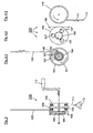
- FIG. 1 a tensioning device 1 for a portable light 500 according to the invention is shown, which biases a folding screen 300.
- the tensioning device 1 consists of a telescopic rod 2 with inner telescopic rods 3, 3 'and outer, in FIG. 1 transparent drawn telescopic sleeves 4, 4 ', which are arranged one inside the other.
- the telescopic sleeves 4, 4 ' are made of stainless steel.
- the telescopic linkage 2 ends at its outer ends in each case in a clamping ring 6, 6 ', to which clamping means 9, 9' are fixed and are clamped by the clamping rings 6, 6 '.
- a lamp holder 7 is arranged, which receives the lamp 8, which is powered by a supply cable 10 with electrical power.
- the tensioning device 1 is shown in the tensioned state for the transportable lamp according to the invention, the telescopic linkage 2 and the pistons 5, 5 'located therein being heated by the heat of the illuminant 8. Due to a higher expansion coefficient of the pistons 5, 5 ', these expand more than the inner diameter of the telescopic sleeves 4, 4'.
- the bulb holder 7 is mounted on a support rod 140 of a stand 141.
- a Switzerlandseilcru 150, 151 ' is attached to the piston 5, 5' and guided by the telescopic sleeves 4, 4 '.
- a handle 150 connects the two traction cables 151, 151 'with each other.
- a tensioning aid 100 is shown, which also serves as a locking means for locking the tensioning device 1.
- the tensioning aid 100 consists of a winding roller 101 about which the pull cable 151 'in FIG. 1 is wound and above the winding roll 100 leaves them again as pull 105.
- the pull cable 105 is connected to the piston 5 'in FIG. 1 connected.
- the winding roller 101 has a brake drum 103.
- In the brake drum 103 is an intake brake 102, which prevents unwinding of the drawstring or the cable 105. Turns the tensioning aid 100 in the FIG.
- the infeed brake 102 prevents unwinding in a clockwise direction, because the inlet brake 102 locks within the brake drum 103.
- counterclockwise winding allows the inlet brake 102, so that the tensioning aid 100 can wind up the tension band or the cable 105 without resistance.
- an optional torsion spring 104 which gives the clamping aid 100 so much torque that it winds the drawstring or the cable 105 against its own rigidity.
- the torsion spring 104 is not primarily intended to serve as Spannkrafterburg ceremonies, but it is possible here to install such a strong torsion spring 104, thereby tightening the clamping device 1 in FIG. 1 is relieved.
- the inlet brake 102 is lifted off the brake drum 103 with the aid of the trigger 160, so that the tensioning aid 100 by unwinding the winding roller 101, the tensioning device 1 in FIG. 1 allows.
- the intake brake this is constructed as a blind-lock, so that the inlet brake 102 by briefly actuation of the winding roll 100 releases its locking and thereby the relaxation of the clamping means 9, 9 'in FIG. 1 allows.
- the inlet brake 102 does not completely solve this, but brakes a movement of the winding roll 100, so that a relaxation of the clamping means 9, 9 'does not happen suddenly, but slowly. As a result, accidents can be avoided.
- FIG. 3 an expanded tensioning aid 200 is shown, which in addition to the previously described tensioning aid 100 another winding roller 110 on a common Has axis 90, wherein the winding roller 110 has a reversed to the clamping aid 100 or the same winding direction.
- This additional roller 110 with wrong or same sense of winding serves to receive a pull cable 111, which can be actuated by a handle 112. If the pulling cable 111 is pulled by the handle 112, then the winding roller 110 is unwound and, at the same time, the tensioning aid 100 wraps itself up and thereby shortens the path of the drawstring or of the cable 105 within the tensioning device 1 FIG. 1 , As a result, the clamping device 1 spans in FIG. 1 because the path between the clamping rings 6, 6 'shortens.
- the roller 110 and the tensioning aid 100 are connected to each other in the extended tensioning aid 200 via a planetary gear 109, so that the roller 110 during unwinding rotates faster than the tensioning aid 100 during clamping.
- a torque gain in the transmission of drawstring 111 to drawstring or cable 105 is achieved, which means a greater ease, especially for large lights with a correspondingly large clamping device 1.
- the winding roller 110 may also have a square in its axial center, in which a crank 113 can be inserted for manual actuation of the crank. As when pulling on the drawstring 111 by the handle 112 can be achieved by turning the crank 113 that the tensioning aid 100, the drawstring or the cable 105 winds and thereby the tensioning device 1 in FIG. 1 stressed.
- the planetary gear 109 can also couple the tensioning aid 100 and the winding roller 110 in such a way that the pulling path of the tension band 111 is shortened relative to the pulling path of the tension band or cable 105.
- This type of coupling is suitable for luminaires whose tensioning device 1 can be tensioned with little force.
- the drawstring 111 does not protrude so far from the tensioning aid 200 after tensioning and thus hangs down unfavorably from the lamp.
- FIG. 4 is the clamping aid 200 off FIG. 3 shown in disassembled form, with a plan view of the tensioning aid 100, the open planetary gear 109 and the winding roller 110 is given.
- the tensioning aid 100 is identical to the tensioning aid except for its seat on the common axis with the planetary gear 109 FIG. 2 .
- tensioning aid 100 is coupled to the sun gear 106 of the planetary gear 109 or meshes with a not shown internal teeth on the rear side of the tensioning aid 100 with the three planet gears 107, 107 ', 107 "of the planetary gear 109.
- the winding roller 110 engages the sun gear 106 or the planetary gears 107, 107', 107" at.
- the winding wheel 110 moves in the counterclockwise direction. If the winding roller is connected to the sun gear 106 of the planetary gear 109, then the central sun gear 106 meshes with the three planet gears 107, 107 ', 107 " Planetary gear 109. As a result, the three planetary gears mesh 107, 107 ', 107 "clockwise against the sun gear 106 and the three planetary gears 107, 107', 107" mesh against an internal toothing, not shown here, which on the rear side of the tensioning aid, not shown here 100 is arranged. As a result, the tensioning aid 100 also rotates in the clockwise direction, so that the tension band or the cable 105 is wound up.
- the torque which is applied to the tensioning aid 100 for clamping the tensioning device 1 in FIG. 1 is required, reduced when transferred to the winding roll 110.
- the winding roller 110 is not connected to the axis of the sun gear 106, but meshes with a not shown internal teeth on the back of the winding roller 110 to the three planetary gears 107, 107 ', 107 "and the clamping device 100 on the axis of the sun gear 106 of Connected to the planetary gear 109, so the torque ratio turns around, which leads to the advantages set out above.
- FIG. 5 is an inventive locking assembly 11 for the telescopic rod 2 of a portable lamp FIG. 1 shown.
- the locking arrangement 11 is arranged within a telescopic linkage 2, which here consists of a telescopic rod 12 and a telescopic sleeve 13.
- a bimetallic bearing 17 On a bimetallic bearing 17, a bimetal 18 is arranged, which curves in the heated state and thus pushes against the train of the locking spring 16, the bolt 15 to the outside.
- the bolt 15 can protrude from a recess 19 in the telescopic sleeve 13 and thus prevent the expansion of the telescopic linkage 2.
- the same locking arrangement 11 is shown, but wherein the bimetal 18 in the cooled state has a different shape and thus the Bar spring 16 pulls the latch 15 in the interior of the telescopic rod 12.
- the bolt 15 thus clears the way for an expansion of the telescopic linkage 2, so that the inner telescopic rod 12 can slide within the telescopic sleeve 13.
- FIG. 6 is a further embodiment of the locking assembly 11 for the telescopic rod 2 of a portable lamp FIG. 1 shown.
- a bimetal which pushes into a latch bolt
- the brass cylinder 170 expands within the telescopic sleeve 13 and thus jammed, whereby the telescopic rod 12 can no longer slide within the telescopic sleeve 13.
- the brass cylinder 170 retracts within the telescoping sleeve 13 and clears the path for sliding the telescoping sleeve 12 within the telescoping sleeve 13.
- FIG. 7 an interruptor arrangement 20 according to the invention for a telescopic rod 2 of a portable lamp is shown.
- a recess 21 is arranged under a breaker contact 22, that a shoe 23 can connect a supply line 24 to form an electrical contact between contacts 25 and contact rod 26.
- the shoe 23 is disposed on a contact rod 26 and rotates about an axis 27 which is disposed in the breaker housing 28.
- a sliding shoe spring 29 presses the sliding block 23 in the direction of the recess 21 of the telescopic rod 12.
- the sliding block 23 is moved into the interior of the interrupter housing 28 by the displaced recess 21 and the contact between the contact rod 26 becomes and contact 25 is opened, so that the supply line 24 is electrically interrupted.
Abstract
Description
Die Erfindung betrifft eine Leuchte mit einem zumindest teilweise mit einer reflektierenden Schicht versehenem Faltschirm, wobei ein oder mehrere bewegliche Spannmittel vorgesehen sind, die den Faltschirm aufspannen und der Faltschirm ein Leuchtmittel im gespannten und im entspannten Zustand umschließt.The invention relates to a luminaire with a folding screen provided at least partially with a reflective layer, wherein one or more movable tensioning means are provided, which span the folding screen and the folding screen encloses a lighting means in the tensioned and in the relaxed state.
Transportable Leuchten mit einem Faltschirm sind als Hand- oder Standleuchten bekannt und werden bevorzugt zur zeitlich begrenzten Ausleuchtung von Räumen oder freiliegenden Flächen eingesetzt. Entsprechend dem vorgesehenen Verwendungszweck kann es sich um Leuchten mit geringer Leistung oder auch um Leuchten bis zu 1.000 Watt und mehr handeln. Letztere werden bevorzugt in Freigelände zur Ausleuchtung beispielsweise einer Baustelle, von Unfallstellen, Großschadenslagen oder Sportveranstaltungen eingesetzt.Transportable lights with a folding screen are known as hand or floor lights and are preferably used for temporary illumination of rooms or exposed areas. Depending on the intended use, it can be lights with low power or even lights up to 1,000 watts and more. The latter are preferably used in open-air areas for the illumination of, for example, a construction site, accident sites, large-scale damage situations or sports events.
Aus der europäischen Patentanmeldung
Der Erfindung liegt die Aufgabe zugrunde, eine transportable Leuchte zur Verfügung zu stellen, welche nicht durch Hitzeschäden zerstört werden kann.The invention has for its object to provide a portable lamp available, which can not be destroyed by heat damage.
Die erfindungsgemäße Aufgabe wird dadurch gelöst, dass zumindest eine Einrichtung vorgesehen ist, welche den gespannten Zustand des Faltschirmes und/oder die Temperatur des Leuchtmittels überwacht und wenigstens eine der Einrichtungen in Abhängigkeit der Temperatur des Leuchtmittels die Spannmittel des Faltschirms arretiert. Weitere vorteilhafte Ausgestaltungen ergeben sich durch die Unteransprüche.The object according to the invention is achieved in that at least one device is provided which monitors the tensioned state of the folding screen and / or the temperature of the lighting means and at least one of the devices locks the clamping means of the folding screen as a function of the temperature of the lighting means. Further advantageous embodiments will become apparent from the dependent claims.
Eine Sicherheitseinrichtung, welche die gleichzeitige Entspannung der Spannmechanik und Warmphase des Leuchtmittels verhindert, sorgt dafür, dass die transportable Leuchte nicht durch Hitzeschäden zerstört werden kann, sodass die Leuchte nicht im entspannten Zustand des Faltschirms eingeschaltet werden oder nach erfolgter Erwärmung eine Entspannung des Faltschirms erfolgen kann. Hierdurch ergibt sich der Vorteil, dass ein versehentlich unter Strom gesetztes Leuchtmittel den Faltschirm nicht durch Hitzeentwicklung zerstört.A safety device which prevents the simultaneous relaxation of the tensioning mechanism and warm phase of the lamp, ensures that the portable lamp can not be destroyed by heat damage, so that the lamp can not be turned on in the relaxed state of Faltschirms or relaxation of the folding screen can be done after heating , This results in the advantage that an inadvertently energized light bulb does not destroy the folding screen by heat.
Erfindungsgemäß kann eines der Elemente der Spannmittel im entspannten Zustand des Faltschirms einen elektrischen Unterbrecher auslösen.According to the invention, one of the elements of the clamping means in the relaxed state of the folding screen trigger an electrical breaker.
Die erfindungsgemäße Sicherheitseinrichtung kann ein Stromunterbrecher sein, welcher so in der transportablen Leuchte angeordnet ist, dass dieser durch ein bewegliches Element des Spannmittels im entspannten Zustand ausgelöst wird. Somit ist die Stromversorgung des Leuchtmittels in diesem Fall unterbrochen. Vorzugsweise ist der Unterbrecher so gestaltet, dass dieser erst im vollständig gespannten Zustand des Faltschirms den Stromkreis schließt. Hierdurch wird verhindert, dass das Leuchtmittel bei vorzeitiger Einschaltung einen nicht vollständig gespannten Schirm zerstört.The safety device according to the invention may be a circuit breaker, which is arranged in the portable lamp, that this is triggered by a movable element of the clamping means in the relaxed state. Thus, the power supply of the lamp is interrupted in this case. Preferably, the breaker is designed so that it closes the circuit only in the fully tensioned state of the folding screen. This prevents the light bulb from destroying an incompletely tensioned screen when switched on prematurely.
Die erfindungsgemäße Einrichtung ist aber nicht begrenzt auf eine Stromunterbrechung, welche verhindert, dass das Leuchtmittel im entspannten Zustand des Faltschirms eingeschaltet werden kann, sondern kann auch eine Einrichtung sein, die durch das Leuchtmittel selbst, beispielweise durch Erwärmung durch das Leuchtmittel, verhindert, dass die Spannmittel entspannt werden können.However, the device according to the invention is not limited to a power interruption, which prevents the light source can be turned on in the relaxed state of the folding screen, but may also be a device that by the light itself, for example by heating by the light source, prevents the Clamping means can be relaxed.
Es hat sich als vorteilhaft herausgestellt, zur Arretierung des Faltschirms im gespannten Zustand ein Element zu nutzen, welches allein durch Wärmeausdehnung die Spannmittel des Faltschirms im erwärmten Zustand arretiert. Es wäre auch möglich, beispielsweise durch einen Elektromagneten, den Faltschirm im gespannten Zustand zu arretieren, wobei der Elektromagnet während der Einschaltphase des Leuchtmittels durch eine Riegelmechanik den Faltschirm arretiert. Ein Element, welches aber allein durch Wärmeausdehnung arretiert, hat aber den Vorteil, dass dieses erst dann die Arretierung löst, wenn das Leuchtmittel des Faltschirms wieder abgekühlt ist. Die Abkühlphase kann dabei wenige Minuten und länger, gegebenenfalls sogar 15 Minuten und länger dauern, wobei in dieser Abkühlphase kein Strom mehr zur Verfügung steht, welcher ein elektrische Verriegelung versorgen könnte.It has proven to be advantageous to use an element for locking the folding screen in the tensioned state, which locks the clamping means of the folding screen in the heated state solely by thermal expansion. It would also be possible, for example by an electromagnet, to lock the folding screen in the tensioned state, wherein the electromagnet locks the folding screen during the switch-on phase of the lighting means by means of a locking mechanism. An element which locks but only by thermal expansion, but has the advantage that this only then releases the lock when the lamp of the folding screen is cooled again. The cooling phase can take a few minutes and longer, possibly even 15 minutes and longer, during which cooling phase, no electricity is available, which could provide an electrical interlock.
Ein Element, welches durch die Wärmeausdehnung die Spannmittel des Faltschirms arretiert, weist somit den Vorteil auf, dass dieses unabhängig von einer Stromversorgung beispielsweise nach Abschalten des Leuchtmittels ist.An element which locks the clamping means of the folding screen by the thermal expansion, thus has the advantage that this is independent of a power supply, for example, after switching off the lamp.
Die Arretiereinrichtung besteht in vorteilhafter Weise aus zwei einander umgreifenden Elementen, die aus unterschiedlichen Werkstoffen gefertigt sind, wobei der Werkstoff des ersten Elementes einen anderen Wärmeausdehnungskoeffizienten als der Werkstoff des zweiten Elementes aufweist. Hierdurch wird erreicht, dass in der Einrichtung zwei Elemente, welche bei Umgebungstemperatur, beispielsweise Außentemperatur, aneinander vorbei gleiten können, aber im erwärmten Zustand sich durch den unterschiedlichen Wärmeausdehnungskoeffizient gegenseitig sperren. In diesem gesperrten Zustand verklemmen die beiden Elemente und lösen sich erst nach erfolgter Abkühlung.The locking device consists advantageously of two mutually encompassing elements, which are made of different materials, wherein the material of the first element has a different thermal expansion coefficient than the material of the second element. This ensures that in the device two elements which at ambient temperature, for example, outside temperature, can slide past each other, but in the heated state lock each other by the different thermal expansion coefficient. In this locked state, the two elements jam and only become detached after cooling has taken place.
In einer ersten beispielhaften Ausgestaltung der Erfindung besteht die Einrichtung aus einem in einem Hohlzylinder gleitenden Kolben, wobei der Werkstoff des Kolbens einen höheren Wärmeausdehnungskoeffizienten als der Werkstoff des Hohlzylinders aufweist. In dieser Ausgestaltung der Erfindung gleitet der Kolben innerhalb des Hohlzylinders beim Spannen des Faltschirms entlang. Ist der Kolben beispielsweise aus Messing gefertigt, welches einen höheren Ausdehnungskoeffizienten aufweist als Edelstahl, und ist der Hohlzylinder aus Edelstahl gefertigt, so kann der Messingkolben, welcher im Edelstahl-Hohlzylinder entlang gleitet, nach Erwärmung nicht mehr in diesem bewegt werden, da der Messingkolben durch Ausdehnung im sich weniger ausdehnenden Edelstahl-Hohlzylinder verklemmt.In a first exemplary embodiment of the invention, the device consists of a piston sliding in a hollow cylinder, wherein the material of the piston has a higher coefficient of thermal expansion than the material of the hollow cylinder. In this embodiment of the invention, the piston slides inside the hollow cylinder during tensioning of the folding screen along. If the piston is made of brass, for example, which has a higher coefficient of expansion than stainless steel, and the hollow cylinder is made of stainless steel, so the brass piston, which slides in stainless steel hollow cylinder, after heating no longer be moved in this, as the brass piston through Expansion in the less expansive stainless steel hollow cylinder jammed.
Die erfindungsgemäße Einrichtung ist aber nicht auf einen Kolben, welcher in einem Hohlzylinder gleitet beschränkt. Es ist auch möglich, dass die wärmeausgelöste Arretiereinrichtung ein auf einem Stab gleitender Ring ist. Hierbei hat es sich von Vorteil erwiesen, wenn der Werkstoff des Ringes einen geringeren Wärmeausdehnungskoeffizienten aufweist als der Werkstoff des Stabes, wobei durch Erwärmung der Stab in dem gleitenden Ring arretiert.However, the device according to the invention is not limited to a piston which slides in a hollow cylinder. It is also possible that the heat-released locking device is a ring sliding on a rod. It has proven to be advantageous if the material of the ring has a lower coefficient of thermal expansion than the material of the rod, which locks by heating the rod in the sliding ring.
Statt einer Einrichtung, welche aneinander oder ineinander gleitet, kann auch eine Riegeleinrichtung verwendet werden, die beispielsweise gleichzeitig als normales Riegelelement den Schirm im gespannten Zustand arretiert, wobei dieses Riegelelement seinerseits durch ein Verriegelungselement von einer manuellen Entriegelung abhält. Es ist beispielsweise möglich, dass ein Bimetall, welches im KaltenInstead of a device which slides against each other or into one another, a locking device can be used, for example, at the same time locks the screen as a normal locking element in the tensioned state, this locking element in turn stops by a locking element of a manual unlocking. It is for example possible that a bimetal, which in the cold
Zustand so angeordnet ist, dass dieses nicht in den Spannweg eines Spannmittels ragt, nach Ausdehnung beziehungsweise nach Verformung durch Hitze in den Spannweg eines Riegelelementes ragt. Beispielhaft seien hier genannt, ein Riegelmechanismus, wie er in Regenschirmen aufzufinden ist, wobei ein Bimetall innerhalb eines Stabes in der Spannmechanik angeordnet ist, das bei Erwärmung in eine Riegelfalle in Form einer Ausnehmung des zentralen Spannelementes der Spannmechanik eingreift. Erst nach dem sich das Bimetall wieder abgekühlt hat und damit die Abkühlung der gesamten Anordnung anzeigt, ist es möglich, den Faltschirm der erfindungsgemäßen Leuchte wieder zu entriegeln und zu entspannen.Condition is arranged so that it does not protrude into the clamping path of a clamping means, after expansion or after deformation by heat protrudes into the clamping path of a locking element. Examples include here a locking mechanism, as it is found in umbrellas, wherein a bimetal is disposed within a rod in the clamping mechanism, which engages when heated in a latch bolt in the form of a recess of the central clamping element of the clamping mechanism. Only after the bimetal has cooled down again and thus indicates the cooling of the entire arrangement, it is possible to unlock the folding screen of the lamp according to the invention again and relax.
Erfindungsgemäß kann das Verriegelungselement ortsfest gehalten werden, wobei das Verriegelungselement ein anderes manuelles Verriegelungselement sperrt, sodass das eigentliche Verriegelungselement nicht mehr manuell ausgelöst werden kann. Es ist aber auch möglich, dass das erfindungsgemäße Verriegelungselement selbst die Bewegung des Spannmittels hemmt oder sperrt.According to the invention, the locking element can be held stationary, wherein the locking element locks another manual locking element, so that the actual locking element can not be triggered manually. But it is also possible that the locking element according to the invention itself inhibits or blocks the movement of the clamping means.
Erfindungsgemäß kann das Verriegelungselement aber auch auf einem beweglichen Spannelement angeordnet werden, wobei das Verriegelungselement im erwärmten Zustand in eine korrespondierende Riegelfalle ragt. Eine Riegelfalle kann hierbei eine Ausnehmung in einem Element der Spannvorrichtung sein, wobei die Riegelfalle so angeordnet ist, dass, wenn das Verriegelungselement in die Riegelfalle ragt, die Spannvorrichtung nicht mehr entspannt werden kann, weil das Verriegelungselement die laterale Bewegung zweier Elemente in der Spannvorrichtung unterbindet.According to the invention, however, the locking element can also be arranged on a movable tensioning element, the locking element projecting in the heated state into a corresponding latching catch. A latch bolt may in this case be a recess in an element of the clamping device, wherein the latch bolt is arranged so that when the locking member projects into the latch bolt, the clamping device can not be relaxed because the locking element prevents the lateral movement of two elements in the tensioning device ,
In vorteilhafter Weise weist die erfindungsgemäße Leuchte mindestens ein Arretiermittel auf, welches den Schirm im unvollständig gespannten Zustand gegenüber Entspannung arretiert, aber gegenüber weiterer Spannung der Spannmechanik öffnet. Hierdurch wird erreicht, dass beim manuellen Spannen des Schirmes, was gegebenenfalls einen hohen Kraftaufwand erfordert, kurzzeitig nachgelassen werden kann, um sich auszuruhen, wobei der Schirm dann nicht, bedingt durch die eigene Spannkraft, wieder zurückschnellt.Advantageously, the lamp according to the invention has at least one locking means which locks the screen in the incompletely tensioned state against relaxation, but opens against further tension of the tensioning mechanism. This ensures that when manually cocking the screen, which may require a lot of effort, can be temporarily reduced to rest, the screen then not back, due to its own resilience, back again.
In vorteilhafter Weise ist speziell für größere Leuchtschirme eine Spannhilfe vorgesehen, welche den Kraftaufwand zum Spannen des Schirmes erniedrigt, wobei das Spannmittel ein Flaschenzug, ein umgelenktes Seil oder ein Getriebe sein kann. Durch die Spannhilfe wird erreicht, dass auch ein größerer Schirm mit relativ geringem Kraftaufwand gespannt werden kann, wobei sich natürlich der manuelle Spannweg durch die Spannhilfe verlängert. Eine Spannhilfe kann ein Flaschenzug sein, wobei die mechanische Aufspannung der Spannmittel durch umgelenkte Seile erfolgt. Es ist aber auch möglich, dass die Spannhilfe ein Getriebe ist, welches eine Wickelrolle antreibt, die selbst mit einem ersten Ende der Spannmittel verbunden ist und ein Zugseil oder ein Kabel aufwickelt, welches mit einem zweiten Ende der Spannmittel verbunden ist. Wenn das Getriebe diese Wickelrolle antreibt, verkürzt sich der Weg zwischen den beiden Spannmitteln durch den Zug der Wickelrolle und so werden die Spannmittel gespannt. Das Getriebe erleichtert dabei das Drehen der Wickelrolle, in dem über eine entsprechende Übersetzung das Drehmoment zum Drehen der Wickelrolle erniedrigt wird. Es ist aber auch denkbar, ein Zahnstangengetriebe zum Spannen der Spannmittel einzusetzen.Advantageously, a tensioning aid is provided especially for larger screens, which reduces the force required to tension the screen, wherein the clamping means may be a pulley, a deflected rope or a transmission. By the tension help is achieved that also a larger screen with relative little effort can be stretched, of course, extends the manual tensioning path by the tensioning aid. A tensioning aid may be a pulley, with the mechanical clamping of the clamping means by deflected ropes. But it is also possible that the tensioning aid is a gear which drives a winding roll, which is itself connected to a first end of the clamping means and a pull rope or a cable wound, which is connected to a second end of the tensioning means. When the gear drives this winding roll, the path between the two clamping means shortened by the train of the winding roll and so the clamping means are tensioned. The gear facilitates the rotation of the winding roll, in which via a corresponding translation, the torque for rotating the winding roll is lowered. But it is also conceivable to use a rack and pinion gear for tensioning the clamping means.
In vorteilhafter Weise liegt die Spannhilfe und das Arretiermittel in einer Einheit vor. Es ist denkbar, sowohl die Spannhilfe als auch das Arretiermittel als einzelne oder als unterschiedliche voneinander unabhängige Aggregate innerhalb der Leuchte vorzusehen. In vorteilhafter Weise ist jedoch die Spannhilfe und das Arretiermittel in einer Einheit vereinigt. Dies hat den Vorteil, dass das Arretiermittel die Spannhilfe direkt arretieren kann und eine Arretierung nicht über unterschiedliche Wege innerhalb der Leuchte vorgenommen wird.Advantageously, the tensioning aid and the locking means are present in one unit. It is conceivable to provide both the tensioning aid and the locking means as individual or as separate mutually independent units within the luminaire. Advantageously, however, the tensioning aid and the locking means are combined in one unit. This has the advantage that the locking means can lock the clamping aid directly and a lock is not made via different paths within the lamp.
Als bevorzugte Ausführungsform einer Leuchte mit einer Spannhilfe und einem Arretiermittel ist eine Leuchte, die ein Zugband oder ein Kabel aufwickelt, wobei die Wickelrolle mit einem ersten Ende der Spannmittel und das Zugband oder das Kabel mit einem zweiten Ende der Spannmittel verbunden ist und die Rolle durch eine Torsionsfeder gespannt das Zugband oder das Kabel beim Spannen der Spannmittel aufwickelt und dabei durch ein Arretiermittel ein Abwickeln des Zugbandes oder des Kabels verhindert und die Entspannung des Faltschirms nur durch Lösen der Arretierung ermöglicht.As a preferred embodiment of a lamp with a tensioning aid and a locking means is a lamp which winds a drawstring or a cable, wherein the winding roll is connected to a first end of the clamping means and the drawstring or the cable to a second end of the clamping means and the roll through a torsion spring tensioned the drawstring or the cable during tensioning of the clamping means and thereby prevents unwinding of the drawstring or the cable by a locking means and allows the relaxation of the folding screen only by releasing the lock.
Die Spannhilfe kann so gestaltet sein, dass sich das Verhältnis von Spannweg und manuellem Auslöseweg gegenüber den oben genannten Ausführungsformen umdreht. Hierdurch wird das zum Spannen der Spannmittel benötigte Drehmoment oder die zum Spannen benötigte Kraft erhöht. Gleichzeitig verkürzt sich der Auslöseweg. Diese Ausführungsform ist besonders praktisch für Leuchten, deren Spannschirm mit bereits geringem Kraftaufwand spannbar ist. Vorteilhaft ist daran, dass ein manuelles Zugseil einen nur sehr kurzen Weg gezogen werden muss. Als Folge davon hängt das Zugseil nicht herunter. Ein langes, herunterhängendes Zugseil könnte im Wind herumschlagen, es könnte sich mit. Kabeln verknoten oder sonst unvorteilhaft und unkontrolliert herabhängen, was für Leuchten im praktischen Einsatz, besonders bei Noteinsätzen als sehr nachteilig empfunden wird.The tensioning aid can be designed such that the ratio of the tensioning path and the manual triggering path is reversed relative to the above-mentioned embodiments. As a result, the torque required for clamping the clamping means or the force required for clamping is increased. At the same time, the trip path is shortened. This embodiment is particularly useful for lights whose tensioning screen can be tensioned with even little effort. The advantage is that a manual pull rope has to be pulled a very short way. When As a result, the pull rope does not hang down. A long, drooping pull rope could knock in the wind, it could come with. Knot cables or otherwise hang unfavorably and uncontrollably, which is perceived for lights in practical use, especially in emergencies as very disadvantageous.
Die Erfindung wird im Nachfolgenden anhand der folgenden Figuren erläutert.The invention will be explained below with reference to the following figures.
Es zeigt
- Fig. 1
- eine erfindungsgemäße transportable Leuchte mit Spannmittel,
- Fig. 2
- eine Spannhilfe für die erfindungsgemäße Leuchte,
- Fig. 3
- eine erweiterte Spannhilfe für die erfindungsgemäße Leuchte,
- Fig. 4
- die erweiterte Spannhilfe auf
Figur 3 in zerlegter Form, - Fig. 5
- eine erfindungsgemäße Bimetallverriegelung im erwärmten und erkalteten Zustand,
- Fig. 6
- eine weitere Wärmeverriegelung und
- Fig. 7
- einen erfindungsgemäßen Unterbrecherkontakt.
- Fig. 1
- a transportable lamp according to the invention with clamping means,
- Fig. 2
- a tensioning aid for the luminaire according to the invention,
- Fig. 3
- an extended tensioning aid for the luminaire according to the invention,
- Fig. 4
- the extended clamping aid on
FIG. 3 in disassembled form, - Fig. 5
- a bimetallic lock according to the invention in the heated and cooled state,
- Fig. 6
- another heat lock and
- Fig. 7
- a breaker contact according to the invention.
In
Die Leuchtmittelfassung 7 ist auf einer Stativstange 140 eines Stativs 141 befestigt. Ein Zugseilpaar 150, 151' ist an den Kolben 5, 5' befestigt und durch die Teleskophülsen 4, 4' geführt. Ein Griff 150 verbindet die beiden Zugseile 151, 151' miteinander. Wenn die Leuchte auf dem Stativ 141, gegebenenfalls in einigen Metern Höhe aufgestellt ist, ermöglicht ein manueller Zug am Zuggriff 150 ein Spannen der Spannvorrichtung 1 in dem die Teleskopstange 3, 3' in die Teleskophülsen 4, 4' gezogen werden und den oberen Spannkranz 6 in Pfeilrichtung nach unten ziehen. Hierdurch nähert sich der obere Spannkranz 6 dem unteren an der Leuchtmittelfassung befestigten Spannkranz 6' und dadurch bewegen sich die Spannmittel 9, 9' nach außen, wie durch die Pfeile angedeutet ist, wodurch sich ein über die Spannmittel 9, 9' gestülpter Leuchtschirm aufspannt.The bulb holder 7 is mounted on a
In
In
In besonderer Ausgestaltung der Erfindung kann vorgesehen sein, dass die Rolle 110 und die Spannhilfe 100 in der erweiterten Spannhilfe 200 über ein Planetengetriebe 109 miteinander verbunden sind, sodass sich die Rolle 110 beim Abwickeln schneller dreht als die Spannhilfe 100 beim Spannen. Hierdurch wird eine Drehmomentverstärkung bei der Übertragung von Zugband 111 auf Zugband oder Kabel 105 erreicht, was besonders für große Leuchten mit entsprechend großer Spannvorrichtung 1 eine Arbeitserleichterung bedeutet. Alternativ oder in Kombination dazu kann die Wickelrolle 110 auch einen Vierkant in seiner Achsmitte aufweisen, in welches eine Kurbel 113 zum manuellen Betätigen der Kurbel hineingesteckt werden kann. Wie beim Ziehen an dem Zugband 111 durch den Handgriff 112 kann durch Drehen der Kurbel 113 erreicht werden, dass die Spannhilfe 100 das Zugband oder das Kabel 105 aufwickelt und dadurch die Spannvorrichtung 1 in
In exakt gegensätzlicher Weise kann das Planetengetriebe 109 die Spannhilfe 100 und die Wickelrolle 110 auch so koppeln, dass sich der Zugweg des Zugbandes 111 gegenüber dem Zugweg des Zugbandes oder Kabels 105 verkürzt. Diese Kopplungsart ist für Leuchten geeignet, deren Spannvorrichtung 1 mit geringer Kraft spannbar ist. Durch die Zugwegverkürzung wird erreicht, dass das Zugband 111 nach dem Spannen nicht so weit aus der Spannhilfe 200 ragt und somit unvorteilhaft von der Leuchte herabhängt.In exactly opposite manner, the
In
In
In
In
- 11
- Spannvorrichtungjig
- 22
- Teleskopgestängetelescopic boom
- 33
- Teleskopstangetelescopic rod
- 44
- Teleskophülse/HohlzylinderTelescopic sleeve / hollow cylinder
- 55
- Kolbenpiston
- 66
- Spannkranzclamping ring
- 77
- LeuchtmittelfassungLamp holder
- 88th
- LeuchtmittelLamp
- 99
- Spannmittelclamping means
- 1010
- Versorgungskabelpower cable
- 1111
- Verriegelungsanordnunglock assembly
- 1212
- Teleskopstangetelescopic rod
- 1313
- Teleskophülsetelescopic sleeve
- 1414
- Riegelachselatch axis
- 1515
- Riegelbars
- 1616
- Riegelfederlatch spring
- 1717
- BimetalllagerBimetalllager
- 1818
- Bimetallbimetallic
- 1919
- Ausnehmungrecess
- 2020
- UnterbrecheranordnungBreaker arrangement
- 2121
- Ausnehmungrecess
- 2222
- UnterbrecherkontaktBreakpoint
- 2323
- Gleitschuhshoe
- 2424
- Versorgungsleitungsupply line
- 2525
- KontaktContact
- 2626
- Kontaktstangecontact rod
- 2727
- Achseaxis
- 2828
- UnterbrechergehäuseBreaker housing
- 2929
- GleitschuhfederGleitschuhfeder
- 9090
- Achseaxis
- 100100
- Spannhilfecocking aid
- 101101
- Wickelrollereel
- 102102
- Einlaufbremseinlet brakes
- 103103
- Bremstrommelbrake drum
- 104104
- Torsionsfedertorsion spring
- 105105
- Zugband/KabelTieback / Cable
- 106106
- Sonnenradsun
- 107107
- Planetenradplanet
- 107'107 '
- Planetenradplanet
- 107"107 '
- Planetenradplanet
- 108108
- Befestigungsanordnungmounting assembly
- 109109
- Planetengetriebeplanetary gear
- 110110
- Wickelrollereel
- 111111
- Zugseilrope
- 112112
- GriffHandle
- 113113
- Kurbelcrank
- 140140
- Stativtripod
- 141141
- StativstangeSupport rod
- 150150
- ZuggriffPull
- 151151
- Zugseilrope
- 151'151 '
- Zugseilrope
- 160160
- Auslösertrigger
- 161161
- BremsbackenlagerBrake shoe bearing
- 170170
- Messingzylinderbrass cylinder
- 200200
- Spannhilfecocking aid
- 300300
- Faltschirmfolding screen
- 500500
- Leuchtelamp
Claims (11)
- Lamp (500) with a folding shade (300) at least partially provided with a reflecting layer, wherein at least one movable tensioning means (2, 9) is provided to stretch the folding shade (300) and the folding shade (300) encloses an illuminant (8),
characterized in that
at least one device (11, 20) is provided which monitors the taut state of the folding shade (300) and/or the temperature of the lamp (8), and at least one of the devices (11, 20) adjusts the tensioning means (2, 9) of the folding shade (300) in dependence to the temperature of the lamp (8). - Lamp (500) according to claim 1,
characterized in that
at least one of the devices (11, 20) interrupts an electric power supply of the illuminant (8) in dependence to the taut state of the tensioning device (1). - Lamp (500) according to one of claims 1 or 2,
characterized in that
the device (11, 20) comprises an element (5, 5') which adjusts a tensioning means element (3) of the tensioning means (2, 9) by thermal expansion. - Lamp (500) according to one of the preceding claims,
characterized in that
the device (11, 20) consists of two elements (4, 4', 5, 5') encompassing each other and being made of different materials, the material of the first element (4, 4') having a thermal expansion coefficient different from that of the second element (5, 5'). - Lamp (500) according to claim 4,
characterized in that
the device (11, 20) is a piston (5, 5') sliding in a hollow cylinder (4, 4'), whereby the material of the piston (5, 5') having a thermal expansion coefficient that is higher than that of the material of the hollow cylinder (4, 4'). - Lamp (500) according to one of the preceding claims,
characterized in that
the device (11, 20) is a ring sliding on a rod (3, 3'). - Lamp (500) according to one of the preceding claims,
characterized in that
at least one element (2) of the tensioning means (9) is locked by a locking element (15), the locking element (15) projecting into the otherwise free tension path of the element (2) of the tensioning means (9) due to the thermal expansion. - Lamp (500) according to claim 7,
characterized in that
the locking element (15) is stationarily held and blocks or stops the movement of the tensioning means (2, 9). - Lamp (500) according to one of claims 7 and 8,
characterized in that
the locking element (15) is arranged on the tensioning element (2) and projects into a corresponding latch catch in a heated state. - Lamp (500) according to one of the preceding claims,
characterized in that
at least one element (21) of the tensioning means (2, 9) activates an electric circuit breaker (20) in a non-stressed state. - Lamp (500) according to one of claims 1 to 6,
characterized in that
a tension aid (100, 200) is provided which changes the expenditure of force for tensioning the tensioning device (1), the tensioning means (100, 200) comprising a pulley block (100), a deflected rope (105) or a gearing (109).
Priority Applications (1)
| Application Number | Priority Date | Filing Date | Title |
|---|---|---|---|
| PL05738427T PL1728023T3 (en) | 2004-03-26 | 2005-03-15 | Portable lamp |
Applications Claiming Priority (2)
| Application Number | Priority Date | Filing Date | Title |
|---|---|---|---|
| DE202004004984U DE202004004984U1 (en) | 2004-03-26 | 2004-03-26 | Transportable light |
| PCT/DE2005/000469 WO2005095845A2 (en) | 2004-03-26 | 2005-03-15 | Portable lamp |
Publications (2)
| Publication Number | Publication Date |
|---|---|
| EP1728023A2 EP1728023A2 (en) | 2006-12-06 |
| EP1728023B1 true EP1728023B1 (en) | 2009-05-20 |
Family
ID=32478554
Family Applications (1)
| Application Number | Title | Priority Date | Filing Date |
|---|---|---|---|
| EP05738427A Active EP1728023B1 (en) | 2004-03-26 | 2005-03-15 | Portable lamp |
Country Status (9)
| Country | Link |
|---|---|
| EP (1) | EP1728023B1 (en) |
| JP (2) | JP4451883B2 (en) |
| CN (1) | CN1938543B (en) |
| AT (1) | ATE431920T1 (en) |
| AU (1) | AU2005228934B2 (en) |
| DE (3) | DE202004004984U1 (en) |
| NZ (1) | NZ549919A (en) |
| PL (1) | PL1728023T3 (en) |
| WO (1) | WO2005095845A2 (en) |
Cited By (1)
| Publication number | Priority date | Publication date | Assignee | Title |
|---|---|---|---|---|
| US11287103B2 (en) | 2019-04-22 | 2022-03-29 | Ism Lighting, Llc. | Low wattage balloon work light |
Families Citing this family (7)
| Publication number | Priority date | Publication date | Assignee | Title |
|---|---|---|---|---|
| CN2847012Y (en) * | 2005-08-29 | 2006-12-13 | 吴松吉 | Improved light balloon decoration lamp |
| JP5341950B2 (en) * | 2011-05-24 | 2013-11-13 | 株式会社モンベル | Lantern shade |
| CN102853281A (en) * | 2011-06-30 | 2013-01-02 | 天津工业大学 | Lamp |
| DE102013002202A1 (en) * | 2013-02-07 | 2014-08-07 | Wacker Neuson Produktion GmbH & Co. KG | Portable lighting device |
| KR101655556B1 (en) * | 2014-11-03 | 2016-09-23 | 현대자동차주식회사 | Lamp capable of being used both as mood lamp and reading lamp |
| KR101812134B1 (en) * | 2016-04-11 | 2017-12-27 | 아이투엠 주식회사 | An Illuminator |
| CN110131612B (en) * | 2019-03-25 | 2021-06-04 | 山东光明园迪儿童家具科技有限公司 | Dustproof desk lamp |
Family Cites Families (7)
| Publication number | Priority date | Publication date | Assignee | Title |
|---|---|---|---|---|
| US3870062A (en) * | 1974-04-22 | 1975-03-11 | Richard Larry Medlin | Illuminated pavilion umbrella |
| FR2678811A1 (en) * | 1991-07-08 | 1993-01-15 | Perrier Noel | MULTI-FUNCTIONAL SOLAR PARASOL. |
| CN2152142Y (en) * | 1993-04-02 | 1994-01-05 | 周贵新 | Foldable glimmer lamp casing |
| US6527418B1 (en) * | 1997-05-27 | 2003-03-04 | Scherba Industries, Inc. | Light cooler |
| DE29910204U1 (en) * | 1999-06-11 | 2000-03-23 | Noelle Juergen | Spring lamp |
| JP2001067911A (en) * | 1999-08-25 | 2001-03-16 | Shigeo Tamaoki | Decorative luminare |
| CN2492942Y (en) * | 2001-08-03 | 2002-05-22 | 黄贵山 | Overhead lamp bulb installing and removing tool |
-
2004
- 2004-03-26 DE DE202004004984U patent/DE202004004984U1/en not_active Expired - Lifetime
-
2005
- 2005-03-15 NZ NZ549919A patent/NZ549919A/en not_active IP Right Cessation
- 2005-03-15 CN CN2005800098174A patent/CN1938543B/en not_active Expired - Fee Related
- 2005-03-15 JP JP2006551715A patent/JP4451883B2/en not_active Expired - Fee Related
- 2005-03-15 DE DE502005007319T patent/DE502005007319D1/en active Active
- 2005-03-15 AT AT05738427T patent/ATE431920T1/en active
- 2005-03-15 PL PL05738427T patent/PL1728023T3/en unknown
- 2005-03-15 WO PCT/DE2005/000469 patent/WO2005095845A2/en active Application Filing
- 2005-03-15 DE DE112005001288T patent/DE112005001288A5/en not_active Withdrawn
- 2005-03-15 AU AU2005228934A patent/AU2005228934B2/en not_active Ceased
- 2005-03-15 EP EP05738427A patent/EP1728023B1/en active Active
-
2009
- 2009-09-11 JP JP2009211119A patent/JP4644297B2/en active Active
Cited By (1)
| Publication number | Priority date | Publication date | Assignee | Title |
|---|---|---|---|---|
| US11287103B2 (en) | 2019-04-22 | 2022-03-29 | Ism Lighting, Llc. | Low wattage balloon work light |
Also Published As
| Publication number | Publication date |
|---|---|
| DE112005001288A5 (en) | 2007-05-24 |
| CN1938543A (en) | 2007-03-28 |
| JP2010015999A (en) | 2010-01-21 |
| WO2005095845A2 (en) | 2005-10-13 |
| NZ549919A (en) | 2009-10-30 |
| AU2005228934A1 (en) | 2005-10-13 |
| PL1728023T3 (en) | 2009-10-30 |
| DE202004004984U1 (en) | 2004-06-03 |
| AU2005228934B2 (en) | 2009-02-26 |
| DE502005007319D1 (en) | 2009-07-02 |
| JP2007522614A (en) | 2007-08-09 |
| ATE431920T1 (en) | 2009-06-15 |
| EP1728023A2 (en) | 2006-12-06 |
| WO2005095845A3 (en) | 2006-05-11 |
| JP4451883B2 (en) | 2010-04-14 |
| CN1938543B (en) | 2012-04-18 |
| JP4644297B2 (en) | 2011-03-02 |
Similar Documents
| Publication | Publication Date | Title |
|---|---|---|
| EP1728023B1 (en) | Portable lamp | |
| EP1059483B1 (en) | Portable lamp | |
| EP3619457B1 (en) | Tripod | |
| EP1279350B1 (en) | Sunshade stick and sunshade comprising same | |
| DE102011052394B4 (en) | Folding reflector | |
| EP1182067A2 (en) | Roller blind for rear window | |
| JP2001081922A (en) | Motor-operated awning | |
| EP1526788B1 (en) | Winch, particularly for driving an umbrella | |
| WO2013017120A2 (en) | Lamp | |
| DE202008004868U1 (en) | Switching drive for a circuit breaker | |
| EP0282851B1 (en) | Swing-down parking barrier | |
| EP2443956B1 (en) | Parasol | |
| CH711463A2 (en) | Stand. | |
| CH594279A5 (en) | Toggle drive unit for medium voltage switch - has symmetrical double spring which reduces bearing load and gives compact construction | |
| EP2013860B1 (en) | Lighting element | |
| DE102008045312A1 (en) | jig | |
| EP1102908B1 (en) | Doorstop | |
| AT5643U1 (en) | SPRING SHAFT | |
| DE102009036213B4 (en) | Parasol gear unit and parasol | |
| WO1993019277A1 (en) | Tilting device for a blind with vertical lamellae | |
| DE102009007962A1 (en) | Building opening-shadow device e.g. toggle catch roller blind, has drive clutch element transmitting output power for deviation of swiveling section, whose dead weight is transmitted to shaft, during reverse swiveling of swiveling section | |
| DE69723064T2 (en) | LOCKING ROD | |
| DE102011109665B4 (en) | closing device | |
| DE2641885A1 (en) | MECHANICAL DRIVE FOR ELECTRIC CIRCUIT-BREAKERS | |
| DE202016106561U1 (en) | Adjustment device for heating circuit valves |
Legal Events
| Date | Code | Title | Description |
|---|---|---|---|
| PUAI | Public reference made under article 153(3) epc to a published international application that has entered the european phase |
Free format text: ORIGINAL CODE: 0009012 |
|
| AK | Designated contracting states |
Kind code of ref document: A2 Designated state(s): AT BE BG CH CY CZ DE DK EE ES FI FR GB GR HU IE IS IT LI LT LU MC NL PL PT RO SE SI SK TR |
|
| AX | Request for extension of the european patent |
Extension state: AL BA HR LV MK YU |
|
| 17P | Request for examination filed |
Effective date: 20061024 |
|
| DAX | Request for extension of the european patent (deleted) | ||
| 17Q | First examination report despatched |
Effective date: 20070913 |
|
| R17C | First examination report despatched (corrected) |
Effective date: 20080411 |
|
| GRAP | Despatch of communication of intention to grant a patent |
Free format text: ORIGINAL CODE: EPIDOSNIGR1 |
|
| GRAS | Grant fee paid |
Free format text: ORIGINAL CODE: EPIDOSNIGR3 |
|
| GRAA | (expected) grant |
Free format text: ORIGINAL CODE: 0009210 |
|
| AK | Designated contracting states |
Kind code of ref document: B1 Designated state(s): AT BE BG CH CY CZ DE DK EE ES FI FR GB GR HU IE IS IT LI LT LU MC NL PL PT RO SE SI SK TR |
|
| REG | Reference to a national code |
Ref country code: GB Ref legal event code: FG4D Free format text: NOT ENGLISH |
|
| REG | Reference to a national code |
Ref country code: CH Ref legal event code: EP |
|
| REG | Reference to a national code |
Ref country code: IE Ref legal event code: FG4D Free format text: LANGUAGE OF EP DOCUMENT: GERMAN |
|
| REF | Corresponds to: |
Ref document number: 502005007319 Country of ref document: DE Date of ref document: 20090702 Kind code of ref document: P |
|
| REG | Reference to a national code |
Ref country code: RO Ref legal event code: EPE |
|
| REG | Reference to a national code |
Ref country code: EE Ref legal event code: FG4A Ref document number: E003540 Country of ref document: EE Effective date: 20090818 |
|
| PG25 | Lapsed in a contracting state [announced via postgrant information from national office to epo] |
Ref country code: PT Free format text: LAPSE BECAUSE OF FAILURE TO SUBMIT A TRANSLATION OF THE DESCRIPTION OR TO PAY THE FEE WITHIN THE PRESCRIBED TIME-LIMIT Effective date: 20090920 Ref country code: LT Free format text: LAPSE BECAUSE OF FAILURE TO SUBMIT A TRANSLATION OF THE DESCRIPTION OR TO PAY THE FEE WITHIN THE PRESCRIBED TIME-LIMIT Effective date: 20090520 Ref country code: FI Free format text: LAPSE BECAUSE OF FAILURE TO SUBMIT A TRANSLATION OF THE DESCRIPTION OR TO PAY THE FEE WITHIN THE PRESCRIBED TIME-LIMIT Effective date: 20090520 Ref country code: ES Free format text: LAPSE BECAUSE OF FAILURE TO SUBMIT A TRANSLATION OF THE DESCRIPTION OR TO PAY THE FEE WITHIN THE PRESCRIBED TIME-LIMIT Effective date: 20090831 |
|
| REG | Reference to a national code |
Ref country code: PL Ref legal event code: T3 |
|
| PG25 | Lapsed in a contracting state [announced via postgrant information from national office to epo] |
Ref country code: SI Free format text: LAPSE BECAUSE OF FAILURE TO SUBMIT A TRANSLATION OF THE DESCRIPTION OR TO PAY THE FEE WITHIN THE PRESCRIBED TIME-LIMIT Effective date: 20090520 Ref country code: IS Free format text: LAPSE BECAUSE OF FAILURE TO SUBMIT A TRANSLATION OF THE DESCRIPTION OR TO PAY THE FEE WITHIN THE PRESCRIBED TIME-LIMIT Effective date: 20090920 Ref country code: SE Free format text: LAPSE BECAUSE OF FAILURE TO SUBMIT A TRANSLATION OF THE DESCRIPTION OR TO PAY THE FEE WITHIN THE PRESCRIBED TIME-LIMIT Effective date: 20090820 |
|
| REG | Reference to a national code |
Ref country code: IE Ref legal event code: FD4D |
|
| PG25 | Lapsed in a contracting state [announced via postgrant information from national office to epo] |
Ref country code: DK Free format text: LAPSE BECAUSE OF FAILURE TO SUBMIT A TRANSLATION OF THE DESCRIPTION OR TO PAY THE FEE WITHIN THE PRESCRIBED TIME-LIMIT Effective date: 20090520 Ref country code: IE Free format text: LAPSE BECAUSE OF FAILURE TO SUBMIT A TRANSLATION OF THE DESCRIPTION OR TO PAY THE FEE WITHIN THE PRESCRIBED TIME-LIMIT Effective date: 20090520 |
|
| REG | Reference to a national code |
Ref country code: HU Ref legal event code: AG4A Ref document number: E006576 Country of ref document: HU |
|
| PLBE | No opposition filed within time limit |
Free format text: ORIGINAL CODE: 0009261 |
|
| STAA | Information on the status of an ep patent application or granted ep patent |
Free format text: STATUS: NO OPPOSITION FILED WITHIN TIME LIMIT |
|
| 26N | No opposition filed |
Effective date: 20100223 |
|
| PG25 | Lapsed in a contracting state [announced via postgrant information from national office to epo] |
Ref country code: MC Free format text: LAPSE BECAUSE OF NON-PAYMENT OF DUE FEES Effective date: 20100331 Ref country code: GR Free format text: LAPSE BECAUSE OF FAILURE TO SUBMIT A TRANSLATION OF THE DESCRIPTION OR TO PAY THE FEE WITHIN THE PRESCRIBED TIME-LIMIT Effective date: 20090821 |
|
| PG25 | Lapsed in a contracting state [announced via postgrant information from national office to epo] |
Ref country code: CY Free format text: LAPSE BECAUSE OF FAILURE TO SUBMIT A TRANSLATION OF THE DESCRIPTION OR TO PAY THE FEE WITHIN THE PRESCRIBED TIME-LIMIT Effective date: 20090520 |
|
| REG | Reference to a national code |
Ref country code: FR Ref legal event code: PLFP Year of fee payment: 12 |
|
| REG | Reference to a national code |
Ref country code: FR Ref legal event code: PLFP Year of fee payment: 13 |
|
| REG | Reference to a national code |
Ref country code: FR Ref legal event code: PLFP Year of fee payment: 14 |
|
| PGFP | Annual fee paid to national office [announced via postgrant information from national office to epo] |
Ref country code: HU Payment date: 20220308 Year of fee payment: 18 Ref country code: GB Payment date: 20220324 Year of fee payment: 18 Ref country code: CH Payment date: 20220324 Year of fee payment: 18 Ref country code: BG Payment date: 20220318 Year of fee payment: 18 Ref country code: AT Payment date: 20220318 Year of fee payment: 18 |
|
| PGFP | Annual fee paid to national office [announced via postgrant information from national office to epo] |
Ref country code: TR Payment date: 20220304 Year of fee payment: 18 Ref country code: SK Payment date: 20220303 Year of fee payment: 18 Ref country code: RO Payment date: 20220303 Year of fee payment: 18 Ref country code: PL Payment date: 20220225 Year of fee payment: 18 Ref country code: NL Payment date: 20220322 Year of fee payment: 18 Ref country code: LU Payment date: 20220322 Year of fee payment: 18 Ref country code: FR Payment date: 20220322 Year of fee payment: 18 Ref country code: EE Payment date: 20220321 Year of fee payment: 18 Ref country code: CZ Payment date: 20220303 Year of fee payment: 18 Ref country code: BE Payment date: 20220322 Year of fee payment: 18 |
|
| PGFP | Annual fee paid to national office [announced via postgrant information from national office to epo] |
Ref country code: IT Payment date: 20220331 Year of fee payment: 18 Ref country code: DE Payment date: 20220530 Year of fee payment: 18 |
|
| REG | Reference to a national code |
Ref country code: DE Ref legal event code: R119 Ref document number: 502005007319 Country of ref document: DE |
|
| REG | Reference to a national code |
Ref country code: EE Ref legal event code: MM4A Ref document number: E003540 Country of ref document: EE Effective date: 20230331 |
|
| PG25 | Lapsed in a contracting state [announced via postgrant information from national office to epo] |
Ref country code: RO Free format text: LAPSE BECAUSE OF NON-PAYMENT OF DUE FEES Effective date: 20230315 Ref country code: CZ Free format text: LAPSE BECAUSE OF NON-PAYMENT OF DUE FEES Effective date: 20230315 |
|
| REG | Reference to a national code |
Ref country code: CH Ref legal event code: PL |
|
| REG | Reference to a national code |
Ref country code: SK Ref legal event code: MM4A Ref document number: E 5884 Country of ref document: SK Effective date: 20230315 Ref country code: NL Ref legal event code: MM Effective date: 20230401 |
|
| REG | Reference to a national code |
Ref country code: AT Ref legal event code: MM01 Ref document number: 431920 Country of ref document: AT Kind code of ref document: T Effective date: 20230315 |
|
| GBPC | Gb: european patent ceased through non-payment of renewal fee |
Effective date: 20230315 |
|
| REG | Reference to a national code |
Ref country code: BE Ref legal event code: MM Effective date: 20230331 |
|
| PG25 | Lapsed in a contracting state [announced via postgrant information from national office to epo] |
Ref country code: NL Free format text: LAPSE BECAUSE OF NON-PAYMENT OF DUE FEES Effective date: 20230401 Ref country code: LU Free format text: LAPSE BECAUSE OF NON-PAYMENT OF DUE FEES Effective date: 20230315 |
|
| PG25 | Lapsed in a contracting state [announced via postgrant information from national office to epo] |
Ref country code: SK Free format text: LAPSE BECAUSE OF NON-PAYMENT OF DUE FEES Effective date: 20230315 |
|
| PG25 | Lapsed in a contracting state [announced via postgrant information from national office to epo] |
Ref country code: GB Free format text: LAPSE BECAUSE OF NON-PAYMENT OF DUE FEES Effective date: 20230315 |
|
| PG25 | Lapsed in a contracting state [announced via postgrant information from national office to epo] |
Ref country code: SK Free format text: LAPSE BECAUSE OF NON-PAYMENT OF DUE FEES Effective date: 20230315 Ref country code: LI Free format text: LAPSE BECAUSE OF NON-PAYMENT OF DUE FEES Effective date: 20230331 Ref country code: HU Free format text: LAPSE BECAUSE OF NON-PAYMENT OF DUE FEES Effective date: 20230316 Ref country code: GB Free format text: LAPSE BECAUSE OF NON-PAYMENT OF DUE FEES Effective date: 20230315 Ref country code: FR Free format text: LAPSE BECAUSE OF NON-PAYMENT OF DUE FEES Effective date: 20230331 Ref country code: EE Free format text: LAPSE BECAUSE OF NON-PAYMENT OF DUE FEES Effective date: 20230331 Ref country code: DE Free format text: LAPSE BECAUSE OF NON-PAYMENT OF DUE FEES Effective date: 20231003 Ref country code: CH Free format text: LAPSE BECAUSE OF NON-PAYMENT OF DUE FEES Effective date: 20230331 Ref country code: AT Free format text: LAPSE BECAUSE OF NON-PAYMENT OF DUE FEES Effective date: 20230315 |
|
| PG25 | Lapsed in a contracting state [announced via postgrant information from national office to epo] |
Ref country code: BE Free format text: LAPSE BECAUSE OF NON-PAYMENT OF DUE FEES Effective date: 20230331 |