EP1710803A2 - Recording and reproducing device - Google Patents
Recording and reproducing device Download PDFInfo
- Publication number
- EP1710803A2 EP1710803A2 EP20060251754 EP06251754A EP1710803A2 EP 1710803 A2 EP1710803 A2 EP 1710803A2 EP 20060251754 EP20060251754 EP 20060251754 EP 06251754 A EP06251754 A EP 06251754A EP 1710803 A2 EP1710803 A2 EP 1710803A2
- Authority
- EP
- European Patent Office
- Prior art keywords
- mpeg
- unit
- recording
- reproducing device
- chassis
- Prior art date
- Legal status (The legal status is an assumption and is not a legal conclusion. Google has not performed a legal analysis and makes no representation as to the accuracy of the status listed.)
- Withdrawn
Links
Images


Classifications
-
- G—PHYSICS
- G11—INFORMATION STORAGE
- G11B—INFORMATION STORAGE BASED ON RELATIVE MOVEMENT BETWEEN RECORD CARRIER AND TRANSDUCER
- G11B33/00—Constructional parts, details or accessories not provided for in the other groups of this subclass
- G11B33/12—Disposition of constructional parts in the apparatus, e.g. of power supply, of modules
- G11B33/125—Disposition of constructional parts in the apparatus, e.g. of power supply, of modules the apparatus comprising a plurality of recording/reproducing devices, e.g. modular arrangements, arrays of disc drives
- G11B33/127—Mounting arrangements of constructional parts onto a chassis
- G11B33/128—Mounting arrangements of constructional parts onto a chassis of the plurality of recording/reproducing devices, e.g. disk drives, onto a chassis
-
- G—PHYSICS
- G06—COMPUTING; CALCULATING OR COUNTING
- G06F—ELECTRIC DIGITAL DATA PROCESSING
- G06F1/00—Details not covered by groups G06F3/00 - G06F13/00 and G06F21/00
- G06F1/16—Constructional details or arrangements
- G06F1/18—Packaging or power distribution
- G06F1/183—Internal mounting support structures, e.g. for printed circuit boards, internal connecting means
- G06F1/184—Mounting of motherboards
-
- G—PHYSICS
- G06—COMPUTING; CALCULATING OR COUNTING
- G06F—ELECTRIC DIGITAL DATA PROCESSING
- G06F1/00—Details not covered by groups G06F3/00 - G06F13/00 and G06F21/00
- G06F1/16—Constructional details or arrangements
- G06F1/18—Packaging or power distribution
- G06F1/183—Internal mounting support structures, e.g. for printed circuit boards, internal connecting means
- G06F1/187—Mounting of fixed and removable disk drives
-
- G—PHYSICS
- G06—COMPUTING; CALCULATING OR COUNTING
- G06F—ELECTRIC DIGITAL DATA PROCESSING
- G06F1/00—Details not covered by groups G06F3/00 - G06F13/00 and G06F21/00
- G06F1/16—Constructional details or arrangements
- G06F1/20—Cooling means
-
- G—PHYSICS
- G11—INFORMATION STORAGE
- G11B—INFORMATION STORAGE BASED ON RELATIVE MOVEMENT BETWEEN RECORD CARRIER AND TRANSDUCER
- G11B25/00—Apparatus characterised by the shape of record carrier employed but not specific to the method of recording or reproducing, e.g. dictating apparatus; Combinations of such apparatus
- G11B25/10—Apparatus capable of using record carriers defined in more than one of the sub-groups G11B25/02 - G11B25/08; Adaptor devices therefor
-
- G—PHYSICS
- G11—INFORMATION STORAGE
- G11B—INFORMATION STORAGE BASED ON RELATIVE MOVEMENT BETWEEN RECORD CARRIER AND TRANSDUCER
- G11B33/00—Constructional parts, details or accessories not provided for in the other groups of this subclass
- G11B33/02—Cabinets; Cases; Stands; Disposition of apparatus therein or thereon
- G11B33/022—Cases
-
- G—PHYSICS
- G11—INFORMATION STORAGE
- G11B—INFORMATION STORAGE BASED ON RELATIVE MOVEMENT BETWEEN RECORD CARRIER AND TRANSDUCER
- G11B33/00—Constructional parts, details or accessories not provided for in the other groups of this subclass
- G11B33/12—Disposition of constructional parts in the apparatus, e.g. of power supply, of modules
- G11B33/125—Disposition of constructional parts in the apparatus, e.g. of power supply, of modules the apparatus comprising a plurality of recording/reproducing devices, e.g. modular arrangements, arrays of disc drives
- G11B33/127—Mounting arrangements of constructional parts onto a chassis
-
- G—PHYSICS
- G11—INFORMATION STORAGE
- G11B—INFORMATION STORAGE BASED ON RELATIVE MOVEMENT BETWEEN RECORD CARRIER AND TRANSDUCER
- G11B33/00—Constructional parts, details or accessories not provided for in the other groups of this subclass
- G11B33/14—Reducing influence of physical parameters, e.g. temperature change, moisture, dust
- G11B33/1406—Reducing the influence of the temperature
- G11B33/1413—Reducing the influence of the temperature by fluid cooling
- G11B33/142—Reducing the influence of the temperature by fluid cooling by air cooling
-
- H—ELECTRICITY
- H01—ELECTRIC ELEMENTS
- H01L—SEMICONDUCTOR DEVICES NOT COVERED BY CLASS H10
- H01L2924/00—Indexing scheme for arrangements or methods for connecting or disconnecting semiconductor or solid-state bodies as covered by H01L24/00
- H01L2924/0001—Technical content checked by a classifier
- H01L2924/0002—Not covered by any one of groups H01L24/00, H01L24/00 and H01L2224/00
Definitions
- the present invention relates to a radiating structure to prevent an electronic part from overheating, and more particularly, to a recording and reproducing device provided with a DVD (Digital Versatile Disc) unit and an HDD (Hard Disk Drive) unit, and relates to a recording and reproducing device capable of efficiently radiating heat generated in an MPEG IC mounted on an MPEG board (circuit board mounted with an MPEG signal processing circuit and a digital circuit) which processes video/audio signals of the DVD unit and the HDD unit.
- An MPEG IC is an integrated circuit which processes video signals in one of the standard MPEG forms.
- a recording and reproducing device such as a DVD device and an HDD device which records/reproduces information on/from a disk is mounted with an MPEG board, on both sides of which an MPEG circuit which compresses or decompresses video/audio signals of the recording and reproducing device is formed, but it is a known fact that MPEG ICs making up the MPEG signal processing circuit and the digital circuit generate heat, producing a high temperature.
- this MPEG board is generally attached below each DVD unit or HDD unit beforehand, and often mounted on a chassis together with these units. Heat generated on this MPEG IC is often cooled by also blowing onto the MPEG IC a cooling wind produced by a cooling fan provided for cooling heat generated in a power transformer which becomes another heat generating source inside the recording and reproducing device and the DVD unit and the HDD unit provided with a motor or the like or by releasing the heat to the outside.
- heat radiating structure radiating heat generated in a semiconductor element such as a power transistor which makes up a switching power circuit
- a method is adopted whereby a metal radiator with a plurality of radiating fins called “heat sinks" formed as a single piece to increase the surface area is attached to the semiconductor element and heat generated in the semiconductor element is released from the surfaces of the plurality of radiating fins of this radiator into the atmosphere.
- Patent Document 1 describes a "radiating structure of a semiconductor element" or the like, which places a circuit board on the top surface of a chassis, provides a protrusion on the chassis, places a radiating spacer at an end of this protrusion, inserts it into a hole formed in the circuit board, solders it to a ground pattern of the circuit board with the radiating surface formed on the semiconductor element oriented face down and dissipates heat in the semiconductor element from the radiating surface onto the chassis through the radiating spacer and the protrusion.
- Patent Document 1 describes a "radiating structure of a semiconductor element" or the like, which places a circuit board on the top surface of a chassis, provides a protrusion on the chassis, places a radiating spacer at an end of this protrusion, inserts it into a hole formed in the circuit board, solders it to a ground pattern of the circuit board with the radiating surface formed on the semiconductor element oriented face down and dissipates heat in the semiconductor element from the radiating surface onto the chassis through the
- the recording and reproducing device combines the VCR unit and the DVD unit or combines the DVD unit and the HDD unit, the recording and reproducing device is becoming smaller and slimmer, which causes heat to be accumulated more easily in the narrowed space, and in this way, how to efficiently dissipate heat of the MPEG IC in the recording and reproducing device is a problem to be solved.
- connections from the MPEG board to the DVD unit and the HDD unit and connections to a main board and power board or the like are performed after the MPEG board is attached below the DVD unit and the HDD unit and the MPEG board is then attached to the chassis together with these units, and therefore the DVD unit and the HDD unit attached above the MPEG board obstruct wiring of a plurality of wires connected from the MPEG board, making the wiring work complicated.
- radiator called a "heat sink”
- the chassis is at a distance from the radiating surface of the semiconductor element only corresponding to the thickness of the circuit board and the distance between the radiating surface and the chassis is small, and it has excellent radiation efficiency to the chassis.
- terminals of an electronic part are inserted into terminal holes formed in the circuit board and soldered on the back of the circuit board or electronic parts are mounted on both the front and back of the circuit board as in the case of a double-side mounting board member, there is a problem that the terminal soldered part and the mounted electronic part constitute obstacles, preventing the plane of the circuit board and the top surface of the chassis from directly contacting each other, deteriorating the radiation effect drastically.
- the present invention has been implemented in view of the above described problems, and it is an object of the present invention to provide a recording and reproducing device provided with a DVD unit, an HDD unit and a VCR unit, which eliminates the need for a large space due to attachment of an expensive and relatively large radiator called a "heat sink" to a semiconductor element as shown in the conventional technology, and also eliminates the need for complicated control over relative positions and engagement dimensions of protrusions formed on the chassis, holes formed in the circuit board and radiating spacer as in the case of the conventional technology shown in above described Patent Document 1.
- the invention provides for efficiently radiating heat generated in an MPEG IC mounted on a circuit board such as an MPEG board which processes video/audio signals for both the DVD unit and the HDD unit using a double-side mounting board member, on both sides of which circuit and soldering patterns are formed, and to which surface mount-type electronic parts having terminals are soldered with the terminals inserted into terminal holes, preventing malfunction which may be caused by heat accumulated in the MPEG IC producing a high temperature, extending the life of this MPEG IC part and improving long-term reliability of the above described recording and reproducing device on which the MPEG IC is mounted.
- the recording and reproducing device is a recording and reproducing device comprising a main board provided with a DVD unit and an HDD unit, which controls overall operation of the recording and reproducing device which constitutes the DVD unit and HDD unit and processes analog video/audio signals and an MPEG board which processes digital video/audio signals of the DVD unit and the HDD unit, wherein a plane of an MPEG IC mounted on the MPEG board is contacted with a bottom face of a chassis of the recording and reproducing device so as to radiate heat generated in the MPEG IC over the bottom face of the chassis.
- a single MPEG board can process digital video/audio signals of both the DVD unit and HDD unit. Furthermore, by making the plane of the MPEG IC mounted on this MPEG board contact the bottom face of the chassis of the recording and reproducing device, it is possible to radiate heat produced in the MPEG IC over the bottom face of the chassis having a surface area wider than the plane of the MPEG IC and release the heat from the bottom face of this chassis having a wide surface area into the atmosphere.
- the recording and reproducing device is the recording and reproducing device according to aspect 1, further comprising a heat sink provided on the bottom face of the chassis having a contacting surface which contacts the bottom face of the chassis, wherein the plane of the MPEG IC is contacted with the plane of the heat sink so as to radiate heat generated in the MPEG IC over the bottom face of the chassis through the heat sink.
- heat generated in the MPEG IC is radiated over the bottom face of the chassis having a surface area wider than the plane of the MPEG IC through this heat sink
- the recording and reproducing device is the recording and reproducing device according to aspect 1 or 2, further comprising a cooling fan at the back of the recording and reproducing device which cools the recording and reproducing device so as to cool heat generated in the MPEG IC radiated over the bottom face of the chassis by the cooling fan.
- heat generated in the MPEG IC radiated over the bottom face of the chassis having a surface area wider than the plane of the MPEG IC is cooled by blowing a cooling wind from the cooling fan placed at the back of the recording and reproducing device or releasing the heat to the outside.
- the recording and reproducing device is the recording and reproducing device according to aspect 3, further comprising a VCR unit inside the recording and reproducing device, wherein the VCR unit and the DVD unit are arranged at the front inside the recording and reproducing device and the DVD unit and the HDD unit are arranged at a certain distance from the cooling fan placed at the back of the recording and reproducing device.
- the DVD unit and HDD unit are arranged at a certain distance from the cooling fan placed at the back of the recording and reproducing device, which reduces the cooing wind from the cooling fan against the DVD unit and HDD unit to a moderate level.
- the recording and reproducing device is the recording and reproducing device according to aspect 3, further comprising a VCR unit inside the recording and reproducing device, wherein the VCR unit and the DVD unit are arranged at the front inside the recording and reproducing device, the DVD unit and the HDD unit are arranged adjacent to the cooling fan placed at the back of the recording and reproducing device at a height different from that of the cooling fan.
- the DVD unit and the HDD unit are arranged adjacent to the cooling fan placed at the back of the recording and reproducing device at a height different from that of the cooling fan, which reduces the cooing wind from the cooling fan against the DVD unit and HDD unit arranged adjacent thereto to a moderate level.
- the recording and reproducing device is the recording and reproducing device according to any one of aspects 1 to 5, further comprising a CPU on the MPEG board, wherein the CPU controls operations of the DVD unit and the HDD unit.
- the CPU is mounted on the MPEG board and operations of both the DVD unit and the HDD unit are controlled by this MPEG board.
- the recording and reproducing device is the recording and reproducing device according to any one of aspects 1 to 5, wherein the MPEG IC comprises a CPU circuit, the MPEG IC processes digital video/audio signals of the DVD unit and the HDD unit and controls operations of the DVD unit and the HDD unit.
- the MPEG IC is provided with a CPU circuit, and the MPEG IC processes digital video/audio signals of the DVD unit and the HDD unit and controls operations of the DVD unit and the HDD unit.
- Embodiment 1 shows a construction whereby heat is radiated with the plane of the MPEG IC contacting the bottom face of the chassis in a layout with the VCR unit placed on the front left side of the device, the DVD unit on the right side, the MPEG board under the DVD unit and the HDD unit and a power board placed overlapping each other behind the DVD unit
- Embodiment 2 shows a construction whereby heat is radiated with the plane of MPEG IC contacting the plane of a heat sink provided on the bottom face of the chassis in a layout with the VCR unit placed on the front left side of the device, the HDD unit behind the VCR unit, the DVD unit on the right side, the MP
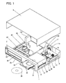
- FIG. 1 is a perspective view showing an overview of a recording and reproducing device provided with a DVD unit, an HDD unit and a VCR unit and
- FIG. 2 is a perspective view showing an MPEG board mounted with an MPEG IC attached to a shielded case.
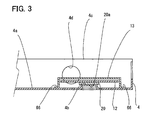
- FIG. 3 is a section view showing the plane of the MPEG IC contacting the contacting surface of the chassis and
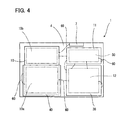
- FIG. 4 is a plan view showing the inner layout of this recording and reproducing device.
- FIG. 5 is a front view showing the inner layout of the recording and reproducing device shown in FIG. 4 and
- FIG. 6 is a side view showing the inner layout of the recording and reproducing device shown in FIG. 4.
- a front cabinet 2 of this recording and reproducing device 1 is provided with a loading/ejection slot 41 of a VCR cassette 42 on the left side and a loading/ejection slot 31 of a DVD disk 35 on the right side, and operation buttons 2a for the user to give instructions to the recording and reproducing device 1 and a display section 2b which displays information on instruction contents, channel and time are placed below these loading/ejection slots 41, 31.
- the part behind the front cabinet 2 is constructed of a chassis 4 and a cover 5 which covers this chassis 4 from above and the VCR cassette 42 is loaded in a VCR unit 40 placed on the front left side inside this recording and reproducing device 1.
- a main board 10 is placed from below this VCR unit 40 backward and a tuner 10c which selects one from broadcast radio waves received by an antenna (not shown) is mounted at the back left side of the main board 10. Furthermore, this main board 10 is mounted with a main microcontroller (not shown) which controls the overall operation of the recording and reproducing device 1 based on an instruction signal from the user received from a remote controller (not shown).
- a tray 32 which carries the DVD disk 35 into a DVD unit 30 is shown drawn out at the front right, ready to load the DVD disk 35.
- the above described tray 32 carries it into the DVD unit 30 and the DVD disk 35 is turned while being held by a clamper 33 and a turntable (not shown) placed thereunder and data is recorded/reproduced on/from the DVD disk 35 by an optical pickup (not shown).
- An MPEG board 12, an upper part of which is covered with a shielded case 13 is placed under this DVD unit 30 in such a way that the plane of an MPEG IC (not shown) mounted thereon contacts a contacting surface (not shown) of a bottom face 4a of the chassis 4 and an HDD unit 50 is placed therebehind.
- a power board 11 which supplies power to each of the circuit boards 10, 12 and each of the units 30, 40, 50 or the like is placed on this HDD unit 50 supported by legs 66 and this power board 11 is mounted with electronic parts such as a power transformer 11a. Furthermore, an upright wall 4c which extends upright from the back of the above described chassis 4 is formed in the chassis 4 and a cooling fan 7 which cools heat generated inside this recording and reproducing device 1 is placed here.
- These circuit boards 10, 11, 12 and units 30, 40, 50 are connected by connecting wires 60.
- This MPEG board 12 is mounted with one CPU (Central Processing Unit) 22 which controls the DVD unit 30 and HDD unit shown in FIG. 1 50 and the above described DVD unit 30 and HDD unit 50 are controlled using the one CPU 22 mounted on this MPEG board 12 as a sub microcontroller under the control of the main microcontroller mounted on the main board 10 to perform operations such as recording and reproduction.
- the MPEG board 12 is further mounted with an MPEG IC 20 which compresses/decompresses digital video/audio signals such as a motion picture and a voice to be recorded/reproduced on/from the DVD disk 35 shown in FIG.
- this MPEG board 12 using a double-side mounting board member is provided with electronic parts 21 higher than this MPEG IC 20 which have terminals and which are mounted on the same side as that of the MPEG IC 20 and soldered on the back of the MPEG board 12 with their terminals inserted into terminal holes (not shown) formed in this MPEG board 12.
- the length of the legs 66 of the shielded case 13 is set to such a height that when the MPEG board 12 is placed on the bottom face 4a of the chassis 4, these electronic parts 21 do not touch the bottom face 4a.
- this MPEG IC 20 which compresses/decompresses video/audio signals generates heat, and therefore in order to radiate this heat, the plane 20a of the above MPEG IC 20 is contacted with a contacting surface 4b of the bottom face 4a of the chassis 4 which will be described later using FIG. 3 and heat is thereby radiated.
- the CPU 22 mounted on the above described MPEG board 12 is not limited to the CPU 22 provided with the sub microcontroller function mounted on the MPEG board 12, but it is also possible to combine the CPU 22 and the MPEG IC 20 as a single piece, mount the MPEG IC 20 including the CPU 22 circuit and the MPEG IC 20 circuit on the MPEG board 12 to process digital video/audio signals of the above described DVD unit 30 and HDD unit 50 and control recording/reproducing operations of the DVD unit 30 and the HDD unit 50.
- the chassis 4 shown in FIG. 3 is placed with a plane 20a of the MPEG IC 20 mounted on the MPEG board 12 placed face down on its bottom face 4a and fixed by the legs 66 of the shielded case 13 supporting this.
- the plane 20a of the MPEG IC 20 mounted on this MPEG board 12 is supported by the legs 66 of the shielded case 13 which are set to be long enough to prevent the high-profile electronic parts 21 mounted on the same side as that of the MPEG IC 20 as described above from touching the bottom face 4a of the chassis 4 and a certain gap is produced between the plane 20a of the MPEG IC 20 and the bottom face 4a of the chassis 4, a contacting surface 4b which forms a stepped salient corresponding to the gap is provided on the bottom face 4a of the chassis 4 facing this MPEG IC 20 and the plane 20a of the IC 20 is contacted with this contacting surface 4b, and heat generated in the MPEG IC 20 is thereby radiated over the bottom face 4a of the chassis 4 through the contacting surface 4b of the chassis 4.
- the cooling fan 7 shown in FIG. 1 is disposed in an opening 4d formed in the upright wall 4c which stands upright at the back of the chassis 4 and the bottom face 4a of the chassis 4 is cooled with a cooling wind from this cooling fan 7, which can prevent heat from being accumulated in this MPEG IC 20 producing a high temperature.
- the electronic part 21 which is higher than the MPEG IC 20 is mounted on the same side as that of the MPEG IC 20 mounted on the MPEG board 12, the length of the legs 66 of the shielded case 13 is extended so that the high-profile electronic parts 21 do not touch the bottom face 4a of the chassis 4, a gap is thereby produced between the plane 20a of the MPEG IC 20 and the bottom face 4a of the chassis 4, a stepped salient is formed on the bottom face 4a of the chassis 4 so that the plane 20a of the MPEG IC 20 contacts this contacting surface 4b, but this MPEG board 12 uses a double-side mounting board member and if the high-profile electronic parts 21 are mounted on the back of the mounting surface of the MPEG IC 20, it is possible to make the plane 20a of the MPEG IC 20 contact the flat surface of the bottom face 4a of the chassis 4, eliminating the need for forming the stepped salient on the bottom face 4a of the chassis 4.
- FIGS. 4 to 6 the layout inside the recording and reproducing device 1 will be explained using FIGS. 4 to 6.
- the main board 10 and the power board 11 shown in FIG. 5 and FIG. 6 are schematically shown when electronic parts (not shown) are mounted thereon, while the MPEG board 12 is shown when an electronic part (not shown) is mounted and a shielded case (not shown) is then attached thereto and the MPEG board 12 is shown with the thickness of the electronic part and shielded case taken into consideration.
- the chassis 4 of this recording and reproducing device 1 is provided with the VCR unit 40 at the front left and the main board 10 extending backward from beneath this VCR unit 40.
- an operation section provided with a remote controller light receiving section (not shown) and operation buttons, and a VCR circuit 10a which controls the operation of the VCR unit 40 which records/reproduces data on/from the VCR cassette 42 shown with FIG. 1 are formed below the VCR unit 40 and a video/audio processing circuit 10b made up of a tuner circuit section (not shown), a video/audio circuit section, an external input/output circuit section and the main microcontroller which controls the operation of this recording and reproducing device 1 in a centralized manner is formed behind the VCR circuit 10a.
- This main microcontroller may also be formed in the VCR circuit 10a to control the operation of the recording and reproducing device 1 in a centralized manner.
- the DVD unit 30 supported by the legs 66 is placed at a certain distance from the cooling fan 7 placed on the upright wall 4c at the back of the chassis 4 and the MPEG board 12 is placed under the DVD unit 30 so as to contact the bottom face 4a of the chassis 4.
- the HDD unit 50 is placed at a position lower than the cooling fan 7 behind this MPEG board 12 and the power board 11 which supplies power to the circuit boards 10, 12 and the units 30, 40, 50 is supported on the HDD unit 50 by the legs 66. In this way, though the HDD unit 50 shown in FIG. 6 is placed in front of the cooling fan 7, it is placed at a position lower than the cooling fan 7, the cooling wind against the HDD unit 50 is reduced to a moderate level.
- the DVD unit 30 is also placed on the front cabinet 2 side, it is located at a certain distance from the cooling fan 7 placed on the upright wall 4c at the back of the chassis 4 and the cooling wind is likewise reduced to a moderate level, making it possible to improve the dustproof effects of the HDD unit 50 and DVD unit 30 and cool the HDD unit 50 and DVD unit 30 moderately with a moderately reduced cooling wind.
- the cooling fan 7 is set in the opening 4d of the upright wall 4c of the chassis 4 beforehand.
- the main board 10 is mounted on the left side of the bottom face 4a of the chassis 4, the VCR unit 40 is mounted thereon and the main board 10 and cooling fan 7, and the main board 10 and VCR unit 40 are connected by the connection wires 60.
- the MPEG board 12 to which the shielded case 13 is attached is mounted on the bottom face 4a of the chassis 4 at the front right and the HDD unit 50 is mounted on the bottom face 4a of the chassis 4 therebehind.
- connection wires 60 are connected from the MPEG board 12 to the main board 10 and the connection wires 60 are connected from the MPEG board 12 to the HDD unit 50.
- the power board 11 supported by the legs 66. is mounted on the HDD unit 50 and the connection wires 60 are connected from the MPEG board 12 to the power board 11.
- the connection wires 60 are connected from the power board 11 to the main board 10.
- the power board 11 and the HDD unit 50 are connected by the connection wires 60.
- the DVD unit 30 supported by the legs 66 is mounted above the MPEG board 12 and the connection wires 60 are connected from the MPEG board 12 to the DVD unit 30.
- the DVD unit 30 and the power board 11 are connected by the connection wires 60.
- the boards 10, 11, 12 and units 30, 40, 50 within the recording and reproducing device 1 can be assembled by assembling them one atop another from the bottom face 4a of the chassis 4 upward, which facilitates the assembly work. Furthermore, by connecting the connection wires 60 from the MPEG board 12 to the main board 10, power board 11 and HDD unit 50 before mounting the DVD unit 30, it is possible to prevent the DVD unit 30 placed above the MPEG board 12 from obstructing the wiring work and simplify and facilitate the wiring work.
- this recording and reproducing device 1 allows the single MPEG board 12 to process both digital video/audio signals of the DVD unit 30 and the HDD unit 50 and thereby eliminate the need for placing a plurality of separate MPEG boards 12 for the DVD unit 30 and HDD unit 50 or the like. Furthermore, by making the plane 20a of the MPEG IC 20 mounted on this MPEG board 12 contact the bottom face 4a of the chassis 4 of the recording and reproducing device 1, it is possible to radiate heat generated in the MPEG IC 20 to the bottom face 4a of the chassis 4 having a greater surface area than that of the plane 20a of the MPEG IC 20 and efficiently release the heat from the bottom face 4a of this wide chassis 4 into the atmosphere.
- the cooling fan 7 which cools the recording and reproducing device 1 is provided at the back of the recording and reproducing device 1 and it is possible to cool heat generated in the MPEG IC 20 radiated over the bottom face 4a of the chassis 4 which has a wider surface area than that of the plane 20a of the MPEG IC 20 by blowing a cooling wind from the cooling fan 7 thereover or releasing the heat to the outside and thereby efficiently cool the heat generated in the MPEG IC 20 even in the narrow device 1.
- placing the DVD unit 30 at a certain distance from the cooling fan 7 provided at the back of the recording and reproducing device 1 can reduce the cooling wind from the cooling fan 7 to the DVD unit 30 to a moderate level.
- placing the HDD unit 50 adjacent to the cooling fan 7 provided at the back of the recording and reproducing device 1 at a height different from the height of the cooling fan 7 can reduce the cooling wind from the cooling fan 7 to this HDD unit 50 to a moderate level, and thereby prevent the cooling wind from directly blowing over the DVD unit 30 and the HDD unit 50 which must be protected from dust, obtain appropriate cooling efficiency with a moderately reduced cooling wind, reduce dust carried by the cooling wind and entering the device and thereby improve the dustproof effect.
- the one CPU 22 mounted on the MPEG board 12 which processes both digital video/audio signals of the DVD unit 30 and HDD unit 50 can control both operations of the DVD unit 30 and HDD unit 50, and thereby eliminate the need for providing separate control circuit boards for operation control of both the DVD unit 30 and HDD unit 50 or for operation control of the DVD unit 30 and for operation control of the HDD unit 50 or the like in addition to this MPEG board 12, reduce the load of wiring work of connecting these control circuit boards and reduce the size of the recording and reproducing device 1 because there is no need for storage of these control circuit boards.
- FIG. 7 is a perspective view showing a heat sink provided on a bottom face of a chassis and FIG. 8 is a plan view showing the inner layout of this recording and reproducing device.
- FIG. 9 is a front view showing the inner layout of the recording and reproducing device shown in FIG. 8 and
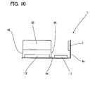
- FIG. 10 is a side view showing the inner layout of the recording and reproducing device shown in FIG. 8.
- FIG. 11 is a rear section view showing the inner layout of the recording and reproducing device shown in FIG. 8.
- Reference numeral 6 shown in FIG. 7 denotes a heat sink, which is placed on a bottom face 4a of a chassis 4 independently of the chassis 4 and a plane 6a of this heat sink 6 has a higher step than that of the bottom face 4a of the chassis 4.
- the chassis 4 is provided with the MPEG board 12 shown in FIG. 2 with the shielded case 13 attached thereto and the heat sink 6 is placed at a position opposite to the MPEG IC 20 mounted on this MPEG board 12. This causes a plane 20a of the MPEG IC 20 to contact the plane 6a of the heat sink 6 including the step height and allows heat generated in the MPEG IC 20 to be radiated over the chassis 4 through the heat sink 6.
- this heat sink 6 is formed from the bottom face 4a of the chassis 4, a cooling wind of a cooling fan (not shown) placed at an opening 4d of an upright wall 4c which stands upright at the back of the chassis 4 is also blown onto the back of the plane 6a which contacts the plane 20a of the MPEG IC 20 or released to the outside, and therefore heat generated in the MPEG IC 20 is radiated over the bottom face 4a of the chassis 4 through the heat sink 6 and the heat sink 6 and the bottom face 4a of the chassis 4 are directly cooled with the cooling wind, and therefore a wider area is cooled with the cooling wind and the cooling efficiency can be improved.
- a cooling wind of a cooling fan (not shown) placed at an opening 4d of an upright wall 4c which stands upright at the back of the chassis 4 is also blown onto the back of the plane 6a which contacts the plane 20a of the MPEG IC 20 or released to the outside, and therefore heat generated in the MPEG IC 20 is radiated over the bottom face 4a of the chassis 4 through the heat sink
- the chassis 4 is provided with a cooling fan 7 on the upright wall 4c at the back right and a main board 10 on which a VCR circuit 10a and video/audio processing circuit 10b are formed on the left side and a VCR unit 40 on the front side above the main board 10. Furthermore, an HDD unit 50 is placed behind the VCR unit 40 supported by legs 66 at a certain distance from the cooling fan 7.
- An MPEG board 12 is placed on the right side of the chassis 4 in such a way that the plane of the heat sink (not shown) placed on the bottom face 4a of the chassis 4 contacts the plane of the MPEG IC and a DVD unit 30 supported by legs 66 is placed above the MPEG board 12 at a certain distance from the cooling fan 7. Moreover, a power board 11 is placed behind the MPEG board 12. This reduces the cooling wind from the cooling fan 7 against the DVD unit 30 and HDD unit 50 placed at a certain distance from the cooling fan 7 to a moderate level and can reduce intruding dust carried by the cooling wind.
- the HDD unit 50 is placed at the position at which this power board 11 is placed, making it possible to reduce the obstruction of the cooling wind from the cooling fan 7 compared to the construction of Embodiment 1 in which the power board 11 is placed thereupon, efficiently cool heat generated in the MPEG IC 20 and moderately cool the DVD unit 30 and HDD unit 50 with a moderately reduced cooling wind.
- connection wires 60 connecting these elements will be explained with reference to the layout shown in FIG. 8.
- the cooling fan 7 is beforehand set in the opening 4d of the upright wall 4c of the chassis 4 first.
- the main board 10 is attached on the left side of the bottom face 4a of the chassis 4, the VCR unit 40 is placed thereabove and the main board 10 and cooling fan 7, and the main board 10 and VCR unit 40 are connected using the connection wires 60.
- the MPEG board 12 is attached on the right side of the bottom face 4a of the chassis 4 and the power board 11 is attached therebehind.
- the MPEG board 12 is connected to the main board 10 and the MPEG board 12 is connected to the power board 11.
- the power board 11 and the main board 10 are connected.
- the DVD unit 30 is attached above the MPEG board 12, the MPEG board 12 and the DVD unit 30 are connected and the power board 11 and DVD unit 30 are connected.
- the HDD unit 50 is attached above the main board 10, the HDD unit 50 and MPEG board 12 are connected and the HDD unit 50 and power board 11 are connected.
- Embodiment 2 by making the plane 20a of the MPEG IC 20 contact the plane 6a of the heat sink 6 provided on the bottom face 4a of the chassis 4, it is possible to efficiently radiate heat generated in the MPEG IC 20 over the bottom face 4a of the chassis 4 which has a wider surface area than the plane 20a of the MPEG IC 20 and thereby release the heat of the MPEG IC 20 from the bottom face 4a of this wide chassis 4 into the atmosphere. Furthermore, even when the electronic part 21 higher than the thickness of the MPEG IC 20 is mounted on the MPEG board 12, it is possible to easily set the distance between the bottom face 4a of the chassis 4 and the MPEG IC 20 and place it at a desired height. Furthermore, since a gap is formed between the heat sink 6 which contacts the plane 20a of the MPEG IC 20 and bottom face 4a of the chassis 4, it is also possible to release heat from the surface of the heat sink 6 into the atmosphere and thereby improve the radiation efficiency.
- heat radiated over the bottom face 4a of the chassis 4 through the heat sink 6 can be efficiently cooled by the cooling fan 7 placed at the back of the recording and reproducing device 1, which can efficiently cool the recording and reproducing device 1 and can also cool the heat sink 6 which contacts the plane 20a of the MPEG IC 20 with a cooling wind and thereby improve the cooling efficiency.
- the DVD unit 30 and the VCR unit 40 provided with loading/ejection slots 31, 41 for a recording medium such as a DVD disk 35 and VCR cassette 42 are arranged on a front cabinet 2 of the recording and reproducing device 1 at the front inside this recording and reproducing device 1 and the HDD unit 50 is placed on the main board 10, the DVD unit 30 and the HDD unit 50 are arranged at a certain distance from the cooling fan 7, and it is possible to thereby reduce the cooling wind from the cooling fan 7 against the DVD unit 30 and HDD unit 50 to a moderate level. This prevents the cooling wind from directly blowing over the DVD unit 30 and the HDD unit 50 which must be protected from dust, obtain moderate cooling efficiency with a moderately reduced cooling wind, and thereby improve the dustproof effect.
- FIG. 12 is a plan view showing the inner layout of this recording and reproducing device.
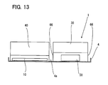
- FIG. 13 is a front view showing the inner layout of the recording and reproducing device shown in FIG. 12 and
- FIG. 14 is a side view showing the inner layout of the recording and reproducing device shown in FIG. 12.
- Embodiment 3 adopts a construction in which heat is radiated with a plane 6a of a heat sink 6 placed on a chassis 4 contacting a plane 20a of an MPEG IC 20 and the layout inside a recording and reproducing device 1 will be explained with reference to FIG. 12 to FIG. 14.
- a cooling fan 7 is placed on an upright wall 4c at the right back of the chassis 4, a main board 10 on which a VCR circuit 10a and video/audio processing circuit 10b are formed is placed on the left side of the chassis 4 and a VCR unit 40 is placed at the front above the main board 10.
- an HDD unit 50 is placed on the right side of the chassis 4 at a certain distance from the cooling fan 7.
- a DVD unit 30 supported by legs 66 is likewise placed on this HDD unit 50 at a certain distance from the cooling fan 7.
- An MPEG board 12 is placed behind the HDD unit 50 in such a way that the plane of the heat sink (not shown) placed on the bottom face 4a of the chassis 4 contacts a plane 20a of the MPEG IC 20 and a power board 11 supported by the legs 66 is placed thereabove. This reduces the cooling wind from the cooling fan 7 against the DVD unit 30 and HDD unit 50 placed at a certain distance from the cooling fan 7 to a moderate level and can reduce dust carried by the cooling wind and can moderately cool the DVD unit 30 and HDD unit 50 with a moderately reduced cooling wind.
- the cooling fan 7 is attached to the opening 4d of the upright wall 4c of the chassis 4 beforehand.
- the main board 10 is attached on the left side of the bottom face 4a of the chassis 4, the VCR unit 40 is placed thereon and the main board 10 and cooling fan 7, and the main board 10 and VCR unit 40 are connected.
- the MPEG board 12 and HDD unit 50 are attached to the bottom face 4a of the chassis 4.
- the MPEG board 12 is connected to the main board 10 and the MPEG board 12 is connected to the HDD unit 50.
- the power board 11 is attached above the MPEG board 12, the power board 11 and main board 10 are connected and the MPEG board 12 is connected to the power board 11.
- the power board 11 and HDD unit 50 are connected.
- the DVD unit 30 is attached above the HDD unit 50 and the MPEG board 12 is connected to the DVD unit 30.
- the DVD unit 30 and power board 11 are connected.
- Embodiment 3 by placing the DVD unit 30 and the VCR unit 40 provided with the loading/ejection slots 31, 41 of a recording medium such as a DVD disk 35 and VCR cassette 42 on the front cabinet 2 of the recording and reproducing device 1 on the front side inside this recording and reproducing device 1 and placing the HDD unit 50 under the DVD unit 30 and thereby placing the DVD unit 30 and HDD unit 50 at a certain distance from the cooling fan 7, it is possible to reduce a cooling wind from the cooling fan 7 against these DVD units 30 and HDD unit 50 to a moderate level. This prevents the cooling wind from directly blowing over the DVD unit 30 and the HDD unit 50 which must be protected from dust, can obtain moderate cooling efficiency with a moderately reduced cooling wind and improve the dustproof effect.
- a recording medium such as a DVD disk 35 and VCR cassette 42
- Embodiment 1 Embodiment 2 and Embodiment 3
- the arrangement of the respective units such as the DVD unit 30, HDD unit 50 and VCR unit 40 and respective circuit boards such as the main board 10, power board 11, MPEG board 12
- the layout inside the recording and reproducing device 1 is not limited to the construction in which the VCR unit 40 is placed on the left side and the DVD unit 30 is placed on the right side, but any mode of construction is possible, for example, reversing these units left to right if it at least allows the loading/ejection slots 41, 31 of the VCR cassette 42 and DVD disk 35 to be arranged at the front of the recording and reproducing device 1.
- the CPU 22 mounted on the MPEG board 12 is not limited to the CPU 22 provided with a sub microcontroller function mounted on the MPEG board 12, but it is also possible to unite the CPU 22 and MPEG IC 20, mount the MPEG IC 20 provided with the CPU 22 circuit and the MPEG IC 20 circuit on the MPEG board 12 to process digital video/audio signals of the DVD unit 30 and HDD unit 50 and control the recording/reproducing operations of the DVD unit 30 and HDD unit 50.
- the contacting surface 4b formed on the bottom face 4a of the chassis 4 is not limited to the mode in which a stepped salient is formed so as to contact the contacting surface 4b, and it is possible to select any appropriate method, for example, placing an electronic part which is higher than the MPEG IC 20 on the back of the MPEG board 12 which allows double-side mounting and thereby causing the plane 20a of the MPEG IC 20 to contact the flat surface of the bottom face 4a of the chassis 4 to radiate heat or change the height of the contacting surface 4b if it is at least possible to efficiently radiate heat.
- a single MPEG board can process digital video/audio signals of both the DVD unit and HDD unit, which eliminates the need for providing a plurality of separate MPEG boards for the DVD unit and HDD unit or the like. Furthermore, by making the plane of the MPEG IC mounted on this MPEG board contact the bottom face of the chassis of the recording and reproducing device, it is possible to radiate heat produced in the MPEG IC over the bottom face of the chassis having a surface area wider than the plane of the MPEG IC and efficiently release the heat from the wide bottom face of this chassis into the atmosphere.
- heat generated in the MPEG IC is radiated over the bottom face of the chassis having a surface area wider than the plane of the MPEG IC through this heat sink by making the plane of the MPEG IC contact the plane of the heat sink provided on the bottom face of the chassis, and it is possible to thereby release the heat generated in the MPEG IC from this wide bottom face of the chassis into the atmosphere. Furthermore, even when an electronic part higher than the thickness of the MPEG IC is mounted on the MPEG board, it is possible to easily set the distance between the bottom face of the chassis and the MPEG IC and place it at a desired height. Furthermore, since a gap is formed between the heat sink which contacts the plane of the MPEG IC and the bottom face of the chassis, it is also possible to release heat from the surface of the heat sink into the atmosphere and thereby improve the radiation efficiency.
- heat generated in the MPEG IC radiated over the bottom face of the chassis having a surface area wider than the plane of the MPEG IC is cooled by blowing a cooling wind from the cooling fan or releasing the heat to the outside, and therefore it is possible to efficiently cool heat generated in the MPEG IC even in a narrow device. Furthermore, when heat is radiated through a heat sink over the bottom face of the chassis, it is possible to efficiently cool the heat radiated over the bottom face of the chassis and also cool the heat sink which contacts the plane of the MPEG IC with a cooling wind and thereby improve the cooling efficiency.
- the DVD unit and HDD unit are arranged at a certain distance from the cooling fan placed at the back of the recording and reproducing device, which reduces the cooing wind from the cooling fan against the DVD unit and the HDD unit to a moderate level.
- This can prevent the cooling wind from directly blowing over the DVD unit and the HDD unit which must be protected from dust, obtain appropriate cooling efficiency with a moderately reduced cooling wind, reduce dust carried by the cooling wind and entering the device and thereby improve the dustproof effect.
- the DVD unit and the HDD unit are arranged adjacent to the cooling fan placed at the back of the recording and reproducing device at a height different from that of the cooling fan, which reduces the cooing wind from the cooling fan against the DVD unit and HDD unit to a moderate level, and can thereby obtain an appropriate cooling effect even when the HDD unit which must be protected from dust is placed adjacent to the cooling fan, reduce dust carried by the cooling wind and entering the device and thereby improve the dustproof effect.
- the CPU mounted on the MPEG board which processes digital video/audio signals of both the DVD unit and the HDD unit can control operations of the DVD unit and the HDD unit, and thereby eliminate the need for providing separate control circuit boards for operation control of both the DVD unit and HDD unit or for operation control of the DVD unit and for operation control of the HDD unit or the like in addition to this MPEG board, reduce the load of wiring work of connecting these control circuit boards and reduce the size of the recording and reproducing device because there is no need for storage of these control circuit boards.
- the MPEG IC is provided with a CPU circuit, and the MPEG IC can process digital video/audio signals of the DVD unit and the HDD unit and control operations of the DVD unit and the HDD unit, and therefore there is no need to mount any CPU in addition to this MPEG IC on the MPEG board and it is possible to reduce the load of mounting an additional CPU on this MPEG board.
Abstract
Description
- The present invention relates to a radiating structure to prevent an electronic part from overheating, and more particularly, to a recording and reproducing device provided with a DVD (Digital Versatile Disc) unit and an HDD (Hard Disk Drive) unit, and relates to a recording and reproducing device capable of efficiently radiating heat generated in an MPEG IC mounted on an MPEG board (circuit board mounted with an MPEG signal processing circuit and a digital circuit) which processes video/audio signals of the DVD unit and the HDD unit. An MPEG IC is an integrated circuit which processes video signals in one of the standard MPEG forms.
- In recent years, a recording and reproducing device such as a DVD device and an HDD device which records/reproduces information on/from a disk is mounted with an MPEG board, on both sides of which an MPEG circuit which compresses or decompresses video/audio signals of the recording and reproducing device is formed, but it is a known fact that MPEG ICs making up the MPEG signal processing circuit and the digital circuit generate heat, producing a high temperature.
- However, this MPEG board is generally attached below each DVD unit or HDD unit beforehand, and often mounted on a chassis together with these units. Heat generated on this MPEG IC is often cooled by also blowing onto the MPEG IC a cooling wind produced by a cooling fan provided for cooling heat generated in a power transformer which becomes another heat generating source inside the recording and reproducing device and the DVD unit and the HDD unit provided with a motor or the like or by releasing the heat to the outside.
- Conventionally, on the other hand, in a heat radiating structure radiating heat generated in a semiconductor element such as a power transistor which makes up a switching power circuit, a method is adopted whereby a metal radiator with a plurality of radiating fins called "heat sinks" formed as a single piece to increase the surface area is attached to the semiconductor element and heat generated in the semiconductor element is released from the surfaces of the plurality of radiating fins of this radiator into the atmosphere.
- Furthermore, for example,
Japanese Patent Laid-Open Publication No. 7-336009 - According to the above described conventional technology, while the above described recording and reproducing device combines the VCR unit and the DVD unit or combines the DVD unit and the HDD unit, the recording and reproducing device is becoming smaller and slimmer, which causes heat to be accumulated more easily in the narrowed space, and in this way, how to efficiently dissipate heat of the MPEG IC in the recording and reproducing device is a problem to be solved. Furthermore, connections from the MPEG board to the DVD unit and the HDD unit and connections to a main board and power board or the like are performed after the MPEG board is attached below the DVD unit and the HDD unit and the MPEG board is then attached to the chassis together with these units, and therefore the DVD unit and the HDD unit attached above the MPEG board obstruct wiring of a plurality of wires connected from the MPEG board, making the wiring work complicated.
- On the other hand, according to the method of attaching the radiator called a "heat sink" to the semiconductor element and radiating heat from this radiator, it is necessary to arrange a relatively large radiator in which a plurality of radiating fins are formed as a single piece around the semiconductor element, and therefore it is necessary to provide a space large enough to place the relatively large radiator in the vicinity of the semiconductor element and attach an expensive radiator made up of a plurality of radiating fins formed as a single piece.
- Furthermore, according to the conventional technology of
Patent Document 1, the chassis is at a distance from the radiating surface of the semiconductor element only corresponding to the thickness of the circuit board and the distance between the radiating surface and the chassis is small, and it has excellent radiation efficiency to the chassis. However, according to specifications whereby terminals of an electronic part are inserted into terminal holes formed in the circuit board and soldered on the back of the circuit board or electronic parts are mounted on both the front and back of the circuit board as in the case of a double-side mounting board member, there is a problem that the terminal soldered part and the mounted electronic part constitute obstacles, preventing the plane of the circuit board and the top surface of the chassis from directly contacting each other, deteriorating the radiation effect drastically. Furthermore, when this radiating structure is applied, it is necessary to provide a protrusion formed on the chassis, holes formed in the circuit board and a radiating spacer, and since these are formed as separate bodies, there is a problem of requiring complicated control over their respective relative positions and engagement dimensions or the like. - The present invention has been implemented in view of the above described problems, and it is an object of the present invention to provide a recording and reproducing device provided with a DVD unit, an HDD unit and a VCR unit, which eliminates the need for a large space due to attachment of an expensive and relatively large radiator called a "heat sink" to a semiconductor element as shown in the conventional technology, and also eliminates the need for complicated control over relative positions and engagement dimensions of protrusions formed on the chassis, holes formed in the circuit board and radiating spacer as in the case of the conventional technology shown in above described
Patent Document 1. Further, the invention provides for efficiently radiating heat generated in an MPEG IC mounted on a circuit board such as an MPEG board which processes video/audio signals for both the DVD unit and the HDD unit using a double-side mounting board member, on both sides of which circuit and soldering patterns are formed, and to which surface mount-type electronic parts having terminals are soldered with the terminals inserted into terminal holes, preventing malfunction which may be caused by heat accumulated in the MPEG IC producing a high temperature, extending the life of this MPEG IC part and improving long-term reliability of the above described recording and reproducing device on which the MPEG IC is mounted. - The recording and reproducing device according to a first aspect is a recording and reproducing device comprising a main board provided with a DVD unit and an HDD unit, which controls overall operation of the recording and reproducing device which constitutes the DVD unit and HDD unit and processes analog video/audio signals and an MPEG board which processes digital video/audio signals of the DVD unit and the HDD unit, wherein a plane of an MPEG IC mounted on the MPEG board is contacted with a bottom face of a chassis of the recording and reproducing device so as to radiate heat generated in the MPEG IC over the bottom face of the chassis.
- According to the construction of
aspect 1, a single MPEG board can process digital video/audio signals of both the DVD unit and HDD unit. Furthermore, by making the plane of the MPEG IC mounted on this MPEG board contact the bottom face of the chassis of the recording and reproducing device, it is possible to radiate heat produced in the MPEG IC over the bottom face of the chassis having a surface area wider than the plane of the MPEG IC and release the heat from the bottom face of this chassis having a wide surface area into the atmosphere. - The recording and reproducing device according to a second aspect is the recording and reproducing device according to
aspect 1, further comprising a heat sink provided on the bottom face of the chassis having a contacting surface which contacts the bottom face of the chassis, wherein the plane of the MPEG IC is contacted with the plane of the heat sink so as to radiate heat generated in the MPEG IC over the bottom face of the chassis through the heat sink. - According to the construction of
aspect 2, heat generated in the MPEG IC is radiated over the bottom face of the chassis having a surface area wider than the plane of the MPEG IC through this heat sink - The recording and reproducing device according to a third aspect is the recording and reproducing device according to
aspect - According to the construction of aspect 3, heat generated in the MPEG IC radiated over the bottom face of the chassis having a surface area wider than the plane of the MPEG IC is cooled by blowing a cooling wind from the cooling fan placed at the back of the recording and reproducing device or releasing the heat to the outside.
- The recording and reproducing device according to a fourth aspect is the recording and reproducing device according to aspect 3, further comprising a VCR unit inside the recording and reproducing device, wherein the VCR unit and the DVD unit are arranged at the front inside the recording and reproducing device and the DVD unit and the HDD unit are arranged at a certain distance from the cooling fan placed at the back of the recording and reproducing device.
- According to the construction of
aspect 4, the DVD unit and HDD unit are arranged at a certain distance from the cooling fan placed at the back of the recording and reproducing device, which reduces the cooing wind from the cooling fan against the DVD unit and HDD unit to a moderate level. - The recording and reproducing device according to a fifth aspect is the recording and reproducing device according to aspect 3, further comprising a VCR unit inside the recording and reproducing device, wherein the VCR unit and the DVD unit are arranged at the front inside the recording and reproducing device, the DVD unit and the HDD unit are arranged adjacent to the cooling fan placed at the back of the recording and reproducing device at a height different from that of the cooling fan.
- According to the construction of
aspect 5, the DVD unit and the HDD unit are arranged adjacent to the cooling fan placed at the back of the recording and reproducing device at a height different from that of the cooling fan, which reduces the cooing wind from the cooling fan against the DVD unit and HDD unit arranged adjacent thereto to a moderate level. - The recording and reproducing device according to a sixth aspect is the recording and reproducing device according to any one of
aspects 1 to 5, further comprising a CPU on the MPEG board, wherein the CPU controls operations of the DVD unit and the HDD unit. - According to the construction of
aspect 6, the CPU is mounted on the MPEG board and operations of both the DVD unit and the HDD unit are controlled by this MPEG board. - The recording and reproducing device according to a seventh aspect is the recording and reproducing device according to any one of
aspects 1 to 5, wherein the MPEG IC comprises a CPU circuit, the MPEG IC processes digital video/audio signals of the DVD unit and the HDD unit and controls operations of the DVD unit and the HDD unit. - According to the construction of
aspect 7, the MPEG IC is provided with a CPU circuit, and the MPEG IC processes digital video/audio signals of the DVD unit and the HDD unit and controls operations of the DVD unit and the HDD unit. -
- FIG. 1 is a perspective view illustrating an overview of a recording and reproducing device provided with a DVD unit, HDD unit and a VCR unit according to
Embodiment 1 of the present invention. - FIG. 2 is a perspective view illustrating an MPEG board mounted with an MPEG IC according to
Embodiment 1 of the present invention mounted on a shielded case. - FIG. 3 is a section view showing the plane of the MPEG IC contacting the contacting surface of the chassis according to
Embodiment 1 of the present invention. - FIG. 4 is a plan view illustrating the inner layout of the recording and reproducing device according to
Embodiment 1 of the present invention. - FIG. 5 is a front view illustrating the inner layout of the recording and reproducing device according to
Embodiment 1 of the present invention. - FIG. 6 is a side view illustrating the inner layout of the recording and reproducing device according to
Embodiment 1 of the present invention. - FIG. 7 is a perspective view illustrating a heat sink provided on a bottom surface of a chassis according to Embodiment 2 of the present invention.
- FIG. 8 is a plan view illustrating the inner layout of the recording and reproducing device according to
Embodiment 2 of the present invention. - FIG. 9 is a front view illustrating the inner layout of the recording and reproducing device according to
Embodiment 2 of the present invention. - FIG. 10 is a side view illustrating the inner layout of the recording and reproducing device according to
Embodiment 2 of the present invention. - FIG. 11 is a rear section view illustrating the inner layout of the recording and reproducing device according to
Embodiment 2 of the present invention. - FIG. 12 is a plan view illustrating the inner layout of a recording and reproducing device according to Embodiment 3 of the present invention.
- FIG. 13 is a front view illustrating the inner layout of the recording and reproducing device according to Embodiment 3 of the present invention.
- FIG. 14 is a side view illustrating the inner layout of the recording and reproducing device according to Embodiment 3 of the present invention.
- As described above, the present invention relates to a recording and reproducing device provided with a DVD unit, an HDD unit and a VCR unit capable of efficiently radiating heat generated in an MPEG IC mounted on an MPEG board which compresses/decompresses digital video/audio signals of the DVD unit and the HDD unit and in explanations of the following embodiments,
Embodiment 1 shows a construction whereby heat is radiated with the plane of the MPEG IC contacting the bottom face of the chassis in a layout with the VCR unit placed on the front left side of the device, the DVD unit on the right side, the MPEG board under the DVD unit and the HDD unit and a power board placed overlapping each other behind the DVD unit, Embodiment 2 shows a construction whereby heat is radiated with the plane of MPEG IC contacting the plane of a heat sink provided on the bottom face of the chassis in a layout with the VCR unit placed on the front left side of the device, the HDD unit behind the VCR unit, the DVD unit on the right side, the MPEG board below the DVD unit and the power board placed behind the DVD unit, and Embodiment 3 shows a construction whereby heat is radiated with the heat sink contacting the MPEG IC as in the case ofEmbodiment 2 in a layout with the VCR unit placed on the front left side of the device, the DVD unit on the right side, the HDD unit below the DVD unit and the MPEG board and the power board placed overlapping each other behind the HDD unit. Details of these embodiments will be explained below. - As the best mode for implementing the present invention, embodiments will be explained using FIG. 1 to FIG. 14 below. It goes without saying that the present invention is easily applicable to cases other than those explained in the embodiments within a range not departing from the essence of the present invention.
- In this embodiment, FIG. 1 is a perspective view showing an overview of a recording and reproducing device provided with a DVD unit, an HDD unit and a VCR unit and FIG. 2 is a perspective view showing an MPEG board mounted with an MPEG IC attached to a shielded case. FIG. 3 is a section view showing the plane of the MPEG IC contacting the contacting surface of the chassis and FIG. 4 is a plan view showing the inner layout of this recording and reproducing device. FIG. 5 is a front view showing the inner layout of the recording and reproducing device shown in FIG. 4 and FIG. 6 is a side view showing the inner layout of the recording and reproducing device shown in FIG. 4.
- An overview of the recording and reproducing device provided with a DVD unit, an HDD unit and a VCR unit will be explained using FIG. 1. A
front cabinet 2 of this recording and reproducingdevice 1 is provided with a loading/ejection slot 41 of aVCR cassette 42 on the left side and a loading/ejection slot 31 of aDVD disk 35 on the right side, andoperation buttons 2a for the user to give instructions to the recording and reproducingdevice 1 and adisplay section 2b which displays information on instruction contents, channel and time are placed below these loading/ejection slots front cabinet 2 is constructed of achassis 4 and acover 5 which covers thischassis 4 from above and theVCR cassette 42 is loaded in aVCR unit 40 placed on the front left side inside this recording and reproducingdevice 1. Amain board 10 is placed from below thisVCR unit 40 backward and atuner 10c which selects one from broadcast radio waves received by an antenna (not shown) is mounted at the back left side of themain board 10. Furthermore, thismain board 10 is mounted with a main microcontroller (not shown) which controls the overall operation of the recording and reproducingdevice 1 based on an instruction signal from the user received from a remote controller (not shown). - Furthermore, a
tray 32 which carries theDVD disk 35 into aDVD unit 30 is shown drawn out at the front right, ready to load theDVD disk 35. When thisDVD disk 35 is loaded, the above describedtray 32 carries it into theDVD unit 30 and theDVD disk 35 is turned while being held by aclamper 33 and a turntable (not shown) placed thereunder and data is recorded/reproduced on/from theDVD disk 35 by an optical pickup (not shown). AnMPEG board 12, an upper part of which is covered with a shieldedcase 13 is placed under thisDVD unit 30 in such a way that the plane of an MPEG IC (not shown) mounted thereon contacts a contacting surface (not shown) of abottom face 4a of thechassis 4 and anHDD unit 50 is placed therebehind. Apower board 11 which supplies power to each of thecircuit boards units HDD unit 50 supported bylegs 66 and thispower board 11 is mounted with electronic parts such as apower transformer 11a. Furthermore, anupright wall 4c which extends upright from the back of the above describedchassis 4 is formed in thechassis 4 and a coolingfan 7 which cools heat generated inside this recording and reproducingdevice 1 is placed here. Thesecircuit boards units wires 60. - Next, the
MPEG board 12 will be explained using FIG. 2. ThisMPEG board 12 is mounted with one CPU (Central Processing Unit) 22 which controls theDVD unit 30 and HDD unit shown in FIG. 1 50 and the above describedDVD unit 30 andHDD unit 50 are controlled using the oneCPU 22 mounted on thisMPEG board 12 as a sub microcontroller under the control of the main microcontroller mounted on themain board 10 to perform operations such as recording and reproduction. TheMPEG board 12 is further mounted with anMPEG IC 20 which compresses/decompresses digital video/audio signals such as a motion picture and a voice to be recorded/reproduced on/from theDVD disk 35 shown in FIG. 1 and an HDD disk (not shown) and the back thereof is covered with the substantially box-like shieldedcase 13 having thelegs 66 to prevent unnecessary radiation by a high-frequency digital signal produced when recorded/reproduced on/from theDVD disk 35 and the HDD disk. Furthermore, thisMPEG board 12 using a double-side mounting board member is provided withelectronic parts 21 higher than thisMPEG IC 20 which have terminals and which are mounted on the same side as that of theMPEG IC 20 and soldered on the back of theMPEG board 12 with their terminals inserted into terminal holes (not shown) formed in thisMPEG board 12. In this way, the length of thelegs 66 of the shieldedcase 13 is set to such a height that when theMPEG board 12 is placed on thebottom face 4a of thechassis 4, theseelectronic parts 21 do not touch thebottom face 4a. Furthermore, when theDVD unit 30 of the above-mentioned recording and reproducingdevice 1 orHDD unit 50 performs recording/reproduction, thisMPEG IC 20 which compresses/decompresses video/audio signals generates heat, and therefore in order to radiate this heat, theplane 20a of theabove MPEG IC 20 is contacted with a contactingsurface 4b of thebottom face 4a of thechassis 4 which will be described later using FIG. 3 and heat is thereby radiated. TheCPU 22 mounted on the above describedMPEG board 12 is not limited to theCPU 22 provided with the sub microcontroller function mounted on theMPEG board 12, but it is also possible to combine theCPU 22 and theMPEG IC 20 as a single piece, mount theMPEG IC 20 including theCPU 22 circuit and theMPEG IC 20 circuit on theMPEG board 12 to process digital video/audio signals of the above describedDVD unit 30 andHDD unit 50 and control recording/reproducing operations of theDVD unit 30 and theHDD unit 50. - Next, the method of radiating heat generated in the
MPEG IC 20 mounted on theMPEG board 12 will be explained. Thechassis 4 shown in FIG. 3 is placed with aplane 20a of theMPEG IC 20 mounted on theMPEG board 12 placed face down on itsbottom face 4a and fixed by thelegs 66 of the shieldedcase 13 supporting this. Theplane 20a of theMPEG IC 20 mounted on thisMPEG board 12 is supported by thelegs 66 of the shieldedcase 13 which are set to be long enough to prevent the high-profileelectronic parts 21 mounted on the same side as that of theMPEG IC 20 as described above from touching thebottom face 4a of thechassis 4 and a certain gap is produced between theplane 20a of theMPEG IC 20 and thebottom face 4a of thechassis 4, a contactingsurface 4b which forms a stepped salient corresponding to the gap is provided on thebottom face 4a of thechassis 4 facing thisMPEG IC 20 and theplane 20a of theIC 20 is contacted with this contactingsurface 4b, and heat generated in theMPEG IC 20 is thereby radiated over thebottom face 4a of thechassis 4 through the contactingsurface 4b of thechassis 4. Furthermore, the coolingfan 7 shown in FIG. 1 is disposed in anopening 4d formed in theupright wall 4c which stands upright at the back of thechassis 4 and thebottom face 4a of thechassis 4 is cooled with a cooling wind from this coolingfan 7, which can prevent heat from being accumulated in thisMPEG IC 20 producing a high temperature. - According to above described FIG. 2 and FIG. 3, the
electronic part 21 which is higher than theMPEG IC 20 is mounted on the same side as that of theMPEG IC 20 mounted on theMPEG board 12, the length of thelegs 66 of the shieldedcase 13 is extended so that the high-profileelectronic parts 21 do not touch thebottom face 4a of thechassis 4, a gap is thereby produced between theplane 20a of theMPEG IC 20 and thebottom face 4a of thechassis 4, a stepped salient is formed on thebottom face 4a of thechassis 4 so that theplane 20a of theMPEG IC 20 contacts this contactingsurface 4b, but thisMPEG board 12 uses a double-side mounting board member and if the high-profileelectronic parts 21 are mounted on the back of the mounting surface of theMPEG IC 20, it is possible to make theplane 20a of theMPEG IC 20 contact the flat surface of thebottom face 4a of thechassis 4, eliminating the need for forming the stepped salient on thebottom face 4a of thechassis 4. - Next, the layout inside the recording and reproducing
device 1 will be explained using FIGS. 4 to 6. Here, themain board 10 and thepower board 11 shown in FIG. 5 and FIG. 6 are schematically shown when electronic parts (not shown) are mounted thereon, while theMPEG board 12 is shown when an electronic part (not shown) is mounted and a shielded case (not shown) is then attached thereto and theMPEG board 12 is shown with the thickness of the electronic part and shielded case taken into consideration. Thechassis 4 of this recording and reproducingdevice 1 is provided with theVCR unit 40 at the front left and themain board 10 extending backward from beneath thisVCR unit 40. On thismain board 10, an operation section provided with a remote controller light receiving section (not shown) and operation buttons, and aVCR circuit 10a which controls the operation of theVCR unit 40 which records/reproduces data on/from theVCR cassette 42 shown with FIG. 1 are formed below theVCR unit 40 and a video/audio processing circuit 10b made up of a tuner circuit section (not shown), a video/audio circuit section, an external input/output circuit section and the main microcontroller which controls the operation of this recording and reproducingdevice 1 in a centralized manner is formed behind theVCR circuit 10a. This main microcontroller may also be formed in theVCR circuit 10a to control the operation of the recording and reproducingdevice 1 in a centralized manner. - Furthermore, the
DVD unit 30 supported by thelegs 66 is placed at a certain distance from the coolingfan 7 placed on theupright wall 4c at the back of thechassis 4 and theMPEG board 12 is placed under theDVD unit 30 so as to contact thebottom face 4a of thechassis 4. Furthermore, theHDD unit 50 is placed at a position lower than the coolingfan 7 behind thisMPEG board 12 and thepower board 11 which supplies power to thecircuit boards units HDD unit 50 by thelegs 66. In this way, though theHDD unit 50 shown in FIG. 6 is placed in front of the coolingfan 7, it is placed at a position lower than the coolingfan 7, the cooling wind against theHDD unit 50 is reduced to a moderate level. This can reduce dust carried by the cooling wind entering theHDD unit 50. Furthermore, since theDVD unit 30 is also placed on thefront cabinet 2 side, it is located at a certain distance from the coolingfan 7 placed on theupright wall 4c at the back of thechassis 4 and the cooling wind is likewise reduced to a moderate level, making it possible to improve the dustproof effects of theHDD unit 50 andDVD unit 30 and cool theHDD unit 50 andDVD unit 30 moderately with a moderately reduced cooling wind. - Next, the order in which the respective circuit boards and respective units are attached and the procedure for wiring the
connection wires 60 for connecting these elements will be explained using FIG. 1, FIG. 4. The coolingfan 7 is set in theopening 4d of theupright wall 4c of thechassis 4 beforehand. Furthermore, themain board 10 is mounted on the left side of thebottom face 4a of thechassis 4, theVCR unit 40 is mounted thereon and themain board 10 and coolingfan 7, and themain board 10 andVCR unit 40 are connected by theconnection wires 60. Furthermore, theMPEG board 12 to which the shieldedcase 13 is attached is mounted on thebottom face 4a of thechassis 4 at the front right and theHDD unit 50 is mounted on thebottom face 4a of thechassis 4 therebehind. Here, theconnection wires 60 are connected from theMPEG board 12 to themain board 10 and theconnection wires 60 are connected from theMPEG board 12 to theHDD unit 50. Next, thepower board 11 supported by thelegs 66. is mounted on theHDD unit 50 and theconnection wires 60 are connected from theMPEG board 12 to thepower board 11. Furthermore, theconnection wires 60 are connected from thepower board 11 to themain board 10. Next, thepower board 11 and theHDD unit 50 are connected by theconnection wires 60. Next, theDVD unit 30 supported by thelegs 66 is mounted above theMPEG board 12 and theconnection wires 60 are connected from theMPEG board 12 to theDVD unit 30. Next, theDVD unit 30 and thepower board 11 are connected by theconnection wires 60. Using these procedures, theboards units device 1 can be assembled by assembling them one atop another from thebottom face 4a of thechassis 4 upward, which facilitates the assembly work. Furthermore, by connecting theconnection wires 60 from theMPEG board 12 to themain board 10,power board 11 andHDD unit 50 before mounting theDVD unit 30, it is possible to prevent theDVD unit 30 placed above theMPEG board 12 from obstructing the wiring work and simplify and facilitate the wiring work. - According to above described
Embodiment 1, this recording and reproducingdevice 1 allows thesingle MPEG board 12 to process both digital video/audio signals of theDVD unit 30 and theHDD unit 50 and thereby eliminate the need for placing a plurality ofseparate MPEG boards 12 for theDVD unit 30 andHDD unit 50 or the like. Furthermore, by making theplane 20a of theMPEG IC 20 mounted on thisMPEG board 12 contact thebottom face 4a of thechassis 4 of the recording and reproducingdevice 1, it is possible to radiate heat generated in theMPEG IC 20 to thebottom face 4a of thechassis 4 having a greater surface area than that of theplane 20a of theMPEG IC 20 and efficiently release the heat from thebottom face 4a of thiswide chassis 4 into the atmosphere. - This eliminates the need for separate members such as an expensive and relatively large radiator having a plurality of radiating fins as in the case of the conventional example, the need for a large space due to the use of this radiator and can reduce the size and thickness of the recording and reproducing
device 1. Furthermore, since heat is radiated with theplane 20a of theMPEG IC 20 directly contacting thebottom face 4a of thechassis 4, there is no need for the accuracy of relative positions and engagement dimensions of the protrusions, holes and radiating spacer as in the case ofPatent Document 1 and there is no need for complicated control over relative positions and engagement dimensions. Furthermore, by forming a stepped salient on thebottom face 4a of thechassis 4 for contact, it is possible to place theMPEG IC 20 at a position higher than thisbottom face 4a of thechassis 4 and contact it, prevent other electronic parts mounted on the circuit board from becoming obstacles as in the case ofPatent Document 1 and make the device also applicable to the specifications whereby the electronic parts are mounted on both sides of the circuit board or the electronic part is mounted with its terminals inserted into terminal holes formed in the circuit board. Furthermore, by efficiently radiating heat generated in theMPEG IC 20 in this way, it is possible to prevent malfunction caused by a high temperature due to the accumulated heat of theMPEG IC 20, extend the life of the part of thisMPEG IC 20 and improve the long-term reliability of the recording and reproducingdevice 1 mounted with theMPEG board 12 provided with thisMPEG IC 20. - The cooling
fan 7 which cools the recording and reproducingdevice 1 is provided at the back of the recording and reproducingdevice 1 and it is possible to cool heat generated in theMPEG IC 20 radiated over thebottom face 4a of thechassis 4 which has a wider surface area than that of theplane 20a of theMPEG IC 20 by blowing a cooling wind from the coolingfan 7 thereover or releasing the heat to the outside and thereby efficiently cool the heat generated in theMPEG IC 20 even in thenarrow device 1. Furthermore, when heat is radiated through aheat sink 6 over thebottom face 4a of thechassis 4, it is possible to efficiently cool the heat radiated over thebottom face 4a of thechassis 4 and also cool theheat sink 6 which contacts theplane 20a of theMPEG IC 20 with a cooling wind and thereby improve the cooling efficiency. - Furthermore, placing the
DVD unit 30 at a certain distance from the coolingfan 7 provided at the back of the recording and reproducingdevice 1 can reduce the cooling wind from the coolingfan 7 to theDVD unit 30 to a moderate level. Furthermore, placing theHDD unit 50 adjacent to the coolingfan 7 provided at the back of the recording and reproducingdevice 1 at a height different from the height of the coolingfan 7 can reduce the cooling wind from the coolingfan 7 to thisHDD unit 50 to a moderate level, and thereby prevent the cooling wind from directly blowing over theDVD unit 30 and theHDD unit 50 which must be protected from dust, obtain appropriate cooling efficiency with a moderately reduced cooling wind, reduce dust carried by the cooling wind and entering the device and thereby improve the dustproof effect. - Furthermore, the one
CPU 22 mounted on theMPEG board 12 which processes both digital video/audio signals of theDVD unit 30 andHDD unit 50 can control both operations of theDVD unit 30 andHDD unit 50, and thereby eliminate the need for providing separate control circuit boards for operation control of both theDVD unit 30 andHDD unit 50 or for operation control of theDVD unit 30 and for operation control of theHDD unit 50 or the like in addition to thisMPEG board 12, reduce the load of wiring work of connecting these control circuit boards and reduce the size of the recording and reproducingdevice 1 because there is no need for storage of these control circuit boards. - Next,
Embodiment 2 of the present invention will be explained. The same components as those inEmbodiment 1 are assigned the same reference numerals and detailed explanations thereof will be omitted. InEmbodiment 2, FIG. 7 is a perspective view showing a heat sink provided on a bottom face of a chassis and FIG. 8 is a plan view showing the inner layout of this recording and reproducing device. FIG. 9 is a front view showing the inner layout of the recording and reproducing device shown in FIG. 8 and FIG. 10 is a side view showing the inner layout of the recording and reproducing device shown in FIG. 8. Furthermore, FIG. 11 is a rear section view showing the inner layout of the recording and reproducing device shown in FIG. 8. -
Reference numeral 6 shown in FIG. 7 denotes a heat sink, which is placed on abottom face 4a of achassis 4 independently of thechassis 4 and aplane 6a of thisheat sink 6 has a higher step than that of thebottom face 4a of thechassis 4. Thechassis 4 is provided with theMPEG board 12 shown in FIG. 2 with the shieldedcase 13 attached thereto and theheat sink 6 is placed at a position opposite to theMPEG IC 20 mounted on thisMPEG board 12. This causes aplane 20a of theMPEG IC 20 to contact theplane 6a of theheat sink 6 including the step height and allows heat generated in theMPEG IC 20 to be radiated over thechassis 4 through theheat sink 6. Furthermore, since the step height of thisheat sink 6 is formed from thebottom face 4a of thechassis 4, a cooling wind of a cooling fan (not shown) placed at anopening 4d of anupright wall 4c which stands upright at the back of thechassis 4 is also blown onto the back of theplane 6a which contacts theplane 20a of theMPEG IC 20 or released to the outside, and therefore heat generated in theMPEG IC 20 is radiated over thebottom face 4a of thechassis 4 through theheat sink 6 and theheat sink 6 and thebottom face 4a of thechassis 4 are directly cooled with the cooling wind, and therefore a wider area is cooled with the cooling wind and the cooling efficiency can be improved. - Next, the layout inside the recording and reproducing
device 1 will be explained using FIGS. 8 to 11. Thechassis 4 is provided with a coolingfan 7 on theupright wall 4c at the back right and amain board 10 on which aVCR circuit 10a and video/audio processing circuit 10b are formed on the left side and aVCR unit 40 on the front side above themain board 10. Furthermore, anHDD unit 50 is placed behind theVCR unit 40 supported bylegs 66 at a certain distance from the coolingfan 7. AnMPEG board 12 is placed on the right side of thechassis 4 in such a way that the plane of the heat sink (not shown) placed on thebottom face 4a of thechassis 4 contacts the plane of the MPEG IC and aDVD unit 30 supported bylegs 66 is placed above theMPEG board 12 at a certain distance from the coolingfan 7. Moreover, apower board 11 is placed behind theMPEG board 12. This reduces the cooling wind from the coolingfan 7 against theDVD unit 30 andHDD unit 50 placed at a certain distance from the coolingfan 7 to a moderate level and can reduce intruding dust carried by the cooling wind. Furthermore, since only thepower board 11 is placed on thebottom face 4a of thechassis 4 behind theMPEG board 12 placed under theDVD unit 30, theHDD unit 50 is placed at the position at which thispower board 11 is placed, making it possible to reduce the obstruction of the cooling wind from the coolingfan 7 compared to the construction ofEmbodiment 1 in which thepower board 11 is placed thereupon, efficiently cool heat generated in theMPEG IC 20 and moderately cool theDVD unit 30 andHDD unit 50 with a moderately reduced cooling wind. - Furthermore, the order in which the
boards units device 1 are attached and the wiring procedure ofconnection wires 60 connecting these elements will be explained with reference to the layout shown in FIG. 8. As in the case ofEmbodiment 1, the coolingfan 7 is beforehand set in theopening 4d of theupright wall 4c of thechassis 4 first. Furthermore, themain board 10 is attached on the left side of thebottom face 4a of thechassis 4, theVCR unit 40 is placed thereabove and themain board 10 and coolingfan 7, and themain board 10 andVCR unit 40 are connected using theconnection wires 60. Next, theMPEG board 12 is attached on the right side of thebottom face 4a of thechassis 4 and thepower board 11 is attached therebehind. Next, theMPEG board 12 is connected to themain board 10 and theMPEG board 12 is connected to thepower board 11. Next, thepower board 11 and themain board 10 are connected. Next, theDVD unit 30 is attached above theMPEG board 12, theMPEG board 12 and theDVD unit 30 are connected and thepower board 11 andDVD unit 30 are connected. Next, theHDD unit 50 is attached above themain board 10, theHDD unit 50 andMPEG board 12 are connected and theHDD unit 50 andpower board 11 are connected. - In this way, it is possible to attach the
MPEG board 12, connect theMPEG board 12 to themain board 10 andpower board 11, then attach theDVD unit 30 above theMPEG board 12 and connect theMPEG board 12 to theDVD unit 30, and thereby prevent theDVD unit 30 from obstructing wiring of these elements and simplify and facilitate the assembly work and wiring work of the recording and reproducingdevice 1. - According to above described
Embodiment 2, by making theplane 20a of theMPEG IC 20 contact theplane 6a of theheat sink 6 provided on thebottom face 4a of thechassis 4, it is possible to efficiently radiate heat generated in theMPEG IC 20 over thebottom face 4a of thechassis 4 which has a wider surface area than theplane 20a of theMPEG IC 20 and thereby release the heat of theMPEG IC 20 from thebottom face 4a of thiswide chassis 4 into the atmosphere. Furthermore, even when theelectronic part 21 higher than the thickness of theMPEG IC 20 is mounted on theMPEG board 12, it is possible to easily set the distance between thebottom face 4a of thechassis 4 and theMPEG IC 20 and place it at a desired height. Furthermore, since a gap is formed between theheat sink 6 which contacts theplane 20a of theMPEG IC 20 andbottom face 4a of thechassis 4, it is also possible to release heat from the surface of theheat sink 6 into the atmosphere and thereby improve the radiation efficiency. - Furthermore, heat radiated over the
bottom face 4a of thechassis 4 through theheat sink 6 can be efficiently cooled by the coolingfan 7 placed at the back of the recording and reproducingdevice 1, which can efficiently cool the recording and reproducingdevice 1 and can also cool theheat sink 6 which contacts theplane 20a of theMPEG IC 20 with a cooling wind and thereby improve the cooling efficiency. - Furthermore, the
DVD unit 30 and theVCR unit 40 provided with loading/ejection slots DVD disk 35 andVCR cassette 42 are arranged on afront cabinet 2 of the recording and reproducingdevice 1 at the front inside this recording and reproducingdevice 1 and theHDD unit 50 is placed on themain board 10, theDVD unit 30 and theHDD unit 50 are arranged at a certain distance from the coolingfan 7, and it is possible to thereby reduce the cooling wind from the coolingfan 7 against theDVD unit 30 andHDD unit 50 to a moderate level. This prevents the cooling wind from directly blowing over theDVD unit 30 and theHDD unit 50 which must be protected from dust, obtain moderate cooling efficiency with a moderately reduced cooling wind, and thereby improve the dustproof effect. - Next, Embodiment 3 of the present invention will be explained. The same components as those in
Embodiment 1 are assigned the same reference numerals and detailed explanations thereof will be omitted. In Embodiment 3, FIG. 12 is a plan view showing the inner layout of this recording and reproducing device. FIG. 13 is a front view showing the inner layout of the recording and reproducing device shown in FIG. 12 and FIG. 14 is a side view showing the inner layout of the recording and reproducing device shown in FIG. 12. - As in the case of
Embodiment 2, Embodiment 3 adopts a construction in which heat is radiated with aplane 6a of aheat sink 6 placed on achassis 4 contacting aplane 20a of anMPEG IC 20 and the layout inside a recording and reproducingdevice 1 will be explained with reference to FIG. 12 to FIG. 14. A coolingfan 7 is placed on anupright wall 4c at the right back of thechassis 4, amain board 10 on which aVCR circuit 10a and video/audio processing circuit 10b are formed is placed on the left side of thechassis 4 and aVCR unit 40 is placed at the front above themain board 10. Furthermore, anHDD unit 50 is placed on the right side of thechassis 4 at a certain distance from the coolingfan 7. ADVD unit 30 supported bylegs 66 is likewise placed on thisHDD unit 50 at a certain distance from the coolingfan 7. AnMPEG board 12 is placed behind theHDD unit 50 in such a way that the plane of the heat sink (not shown) placed on thebottom face 4a of thechassis 4 contacts aplane 20a of theMPEG IC 20 and apower board 11 supported by thelegs 66 is placed thereabove. This reduces the cooling wind from the coolingfan 7 against theDVD unit 30 andHDD unit 50 placed at a certain distance from the coolingfan 7 to a moderate level and can reduce dust carried by the cooling wind and can moderately cool theDVD unit 30 andHDD unit 50 with a moderately reduced cooling wind. - Furthermore, the order in which the
boards units device 1 are attached and the wiring procedure of theconnection wires 60 connecting these elements will be explained with reference to the layout shown in FIG. 12. As in the case ofEmbodiment 1 andEmbodiment 2, the coolingfan 7 is attached to theopening 4d of theupright wall 4c of thechassis 4 beforehand. Furthermore, themain board 10 is attached on the left side of thebottom face 4a of thechassis 4, theVCR unit 40 is placed thereon and themain board 10 and coolingfan 7, and themain board 10 andVCR unit 40 are connected. Next, theMPEG board 12 andHDD unit 50 are attached to thebottom face 4a of thechassis 4. Next, theMPEG board 12 is connected to themain board 10 and theMPEG board 12 is connected to theHDD unit 50. Next, thepower board 11 is attached above theMPEG board 12, thepower board 11 andmain board 10 are connected and theMPEG board 12 is connected to thepower board 11. Next, thepower board 11 andHDD unit 50 are connected. Next, theDVD unit 30 is attached above theHDD unit 50 and theMPEG board 12 is connected to theDVD unit 30. Next, theDVD unit 30 andpower board 11 are connected. - This makes it possible to attach the
MPEG board 12, connect theMPEG board 12 to themain board 10,HDD unit 50,power board 11, then attach theDVD unit 30 and connect theMPEG board 12 toDVD unit 30, which prevents theDVD unit 30 from obstructing wiring of these elements and simplifies and facilitates assembly work and wiring work of the recording and reproducingdevice 1. - According to above described Embodiment 3, by placing the
DVD unit 30 and theVCR unit 40 provided with the loading/ejection slots DVD disk 35 andVCR cassette 42 on thefront cabinet 2 of the recording and reproducingdevice 1 on the front side inside this recording and reproducingdevice 1 and placing theHDD unit 50 under theDVD unit 30 and thereby placing theDVD unit 30 andHDD unit 50 at a certain distance from the coolingfan 7, it is possible to reduce a cooling wind from the coolingfan 7 against theseDVD units 30 andHDD unit 50 to a moderate level. This prevents the cooling wind from directly blowing over theDVD unit 30 and theHDD unit 50 which must be protected from dust, can obtain moderate cooling efficiency with a moderately reduced cooling wind and improve the dustproof effect. - Furthermore, as shown in
Embodiment 1,Embodiment 2 and Embodiment 3, by changing the arrangement of the respective units such as theDVD unit 30,HDD unit 50 andVCR unit 40 and respective circuit boards such as themain board 10,power board 11,MPEG board 12, it is possible to increase the degree of freedom in the design of the inner layout of the hybrid machine of the recording and reproducingdevice 1 made up of theDVD unit 30,HDD unit 50 andVCR unit 40 and the overall recording and reproducingdevice 1 including thefront cabinet 2. - The embodiments have been explained in detail so far, but the present invention can be implemented modified in various ways within a range not departing from the essence of the present invention. For example, the layout inside the recording and reproducing
device 1 is not limited to the construction in which theVCR unit 40 is placed on the left side and theDVD unit 30 is placed on the right side, but any mode of construction is possible, for example, reversing these units left to right if it at least allows the loading/ejection slots VCR cassette 42 andDVD disk 35 to be arranged at the front of the recording and reproducingdevice 1. Furthermore, theCPU 22 mounted on theMPEG board 12 is not limited to theCPU 22 provided with a sub microcontroller function mounted on theMPEG board 12, but it is also possible to unite theCPU 22 andMPEG IC 20, mount theMPEG IC 20 provided with theCPU 22 circuit and theMPEG IC 20 circuit on theMPEG board 12 to process digital video/audio signals of theDVD unit 30 andHDD unit 50 and control the recording/reproducing operations of theDVD unit 30 andHDD unit 50. Furthermore, the contactingsurface 4b formed on thebottom face 4a of thechassis 4 is not limited to the mode in which a stepped salient is formed so as to contact the contactingsurface 4b, and it is possible to select any appropriate method, for example, placing an electronic part which is higher than theMPEG IC 20 on the back of theMPEG board 12 which allows double-side mounting and thereby causing theplane 20a of theMPEG IC 20 to contact the flat surface of thebottom face 4a of thechassis 4 to radiate heat or change the height of the contactingsurface 4b if it is at least possible to efficiently radiate heat. - The effects of the present invention are as follows.
- According to the invention of a first aspect, a single MPEG board can process digital video/audio signals of both the DVD unit and HDD unit, which eliminates the need for providing a plurality of separate MPEG boards for the DVD unit and HDD unit or the like. Furthermore, by making the plane of the MPEG IC mounted on this MPEG board contact the bottom face of the chassis of the recording and reproducing device, it is possible to radiate heat produced in the MPEG IC over the bottom face of the chassis having a surface area wider than the plane of the MPEG IC and efficiently release the heat from the wide bottom face of this chassis into the atmosphere. This eliminates the need for separate members such as an expensive and relatively large radiator having a plurality of radiating fins as in the case of the conventional example, the need for a large space due to the use of this radiator and can reduce the size and thickness of the recording and reproducing device. Furthermore, since heat is radiated with the plane of the MPEG IC directly contacting the bottom face of the chassis, there is no need for the accuracy of relative positions and engagement dimensions of the protrusions, holes and radiating spacer as in the case of
Patent Document 1 and there is no need for complicated control over relative positions and engagement dimensions. Furthermore, by forming a stepped salient on the bottom face of the chassis for contact, it is possible to place the MPEG IC at a position higher than this bottom face of the chassis and contact it, prevent other electronic parts mounted on the circuit board from becoming obstacles as in the case ofPatent Document 1 and make the device also applicable to the specifications whereby the electronic parts are mounted on both sides of the circuit board or the electronic part is mounted with its terminals inserted into terminal holes formed in the circuit board. Furthermore, by efficiently radiating heat generated in the MPEG IC in this way, it is possible to prevent malfunction caused by a high temperature due to the accumulated heat of the MPEG IC, extend the life of the part of this MPEG IC and improve the long-term reliability of the recording and reproducing device mounted with the MPEG board provided with this MPEG IC. - According to the invention of a second aspect, heat generated in the MPEG IC is radiated over the bottom face of the chassis having a surface area wider than the plane of the MPEG IC through this heat sink by making the plane of the MPEG IC contact the plane of the heat sink provided on the bottom face of the chassis, and it is possible to thereby release the heat generated in the MPEG IC from this wide bottom face of the chassis into the atmosphere. Furthermore, even when an electronic part higher than the thickness of the MPEG IC is mounted on the MPEG board, it is possible to easily set the distance between the bottom face of the chassis and the MPEG IC and place it at a desired height. Furthermore, since a gap is formed between the heat sink which contacts the plane of the MPEG IC and the bottom face of the chassis, it is also possible to release heat from the surface of the heat sink into the atmosphere and thereby improve the radiation efficiency.
- According to the invention of a third aspect, heat generated in the MPEG IC radiated over the bottom face of the chassis having a surface area wider than the plane of the MPEG IC is cooled by blowing a cooling wind from the cooling fan or releasing the heat to the outside, and therefore it is possible to efficiently cool heat generated in the MPEG IC even in a narrow device. Furthermore, when heat is radiated through a heat sink over the bottom face of the chassis, it is possible to efficiently cool the heat radiated over the bottom face of the chassis and also cool the heat sink which contacts the plane of the MPEG IC with a cooling wind and thereby improve the cooling efficiency.
- According to the invention of a fourth aspect, the DVD unit and HDD unit are arranged at a certain distance from the cooling fan placed at the back of the recording and reproducing device, which reduces the cooing wind from the cooling fan against the DVD unit and the HDD unit to a moderate level. This can prevent the cooling wind from directly blowing over the DVD unit and the HDD unit which must be protected from dust, obtain appropriate cooling efficiency with a moderately reduced cooling wind, reduce dust carried by the cooling wind and entering the device and thereby improve the dustproof effect.
- According to the invention of a fifth aspect, the DVD unit and the HDD unit are arranged adjacent to the cooling fan placed at the back of the recording and reproducing device at a height different from that of the cooling fan, which reduces the cooing wind from the cooling fan against the DVD unit and HDD unit to a moderate level, and can thereby obtain an appropriate cooling effect even when the HDD unit which must be protected from dust is placed adjacent to the cooling fan, reduce dust carried by the cooling wind and entering the device and thereby improve the dustproof effect.
- According to the invention of a sixth aspect, the CPU mounted on the MPEG board which processes digital video/audio signals of both the DVD unit and the HDD unit can control operations of the DVD unit and the HDD unit, and thereby eliminate the need for providing separate control circuit boards for operation control of both the DVD unit and HDD unit or for operation control of the DVD unit and for operation control of the HDD unit or the like in addition to this MPEG board, reduce the load of wiring work of connecting these control circuit boards and reduce the size of the recording and reproducing device because there is no need for storage of these control circuit boards.
- According to the invention of a seventh aspect, the MPEG IC is provided with a CPU circuit, and the MPEG IC can process digital video/audio signals of the DVD unit and the HDD unit and control operations of the DVD unit and the HDD unit, and therefore there is no need to mount any CPU in addition to this MPEG IC on the MPEG board and it is possible to reduce the load of mounting an additional CPU on this MPEG board.
Claims (7)
- A recording and reproducing device comprising:a main board provided with a DVD unit and an HDD unit, which controls overall operation of the recording and reproducing device which constitutes the DVD unit and HDD unit and processes analog video/audio signals; andan MPEG board which processes digital video/audio signals of the DVD unit and the HDD unit,wherein a plane of an MPEG IC mounted on the MPEG board is contacted with a bottom face of a chassis of the recording and reproducing device so as to radiate heat generated in the MPEG IC over the bottom face of the chassis.
- The recording and reproducing device according to claim 1, further comprising a heat sink provided on the bottom face of the chassis having a contacting surface which contacts the bottom face of the chassis, wherein the plane of the MPEG IC is contacted with the plane of the heat sink so as to radiate heat generated in the MPEG IC over the bottom face of the chassis through the heat sink.
- The recording and reproducing device according to claim 1 or 2, further comprising a cooling fan at the back of the recording and reproducing device which cools the recording and reproducing device so as to cool heat generated in the MPEG IC radiated over the bottom face of the chassis by the cooling fan.
- The recording and reproducing device according to claim 3 further comprising a VCR unit inside the recording and reproducing device, wherein the VCR unit and the DVD unit are arranged at the front inside the recording and reproducing device and the DVD unit and the HDD unit are arranged at a certain distance from the cooling fan placed at the back of the recording and reproducing device.
- The recording and reproducing device according to claim 3, further comprising a VCR unit inside the recording and reproducing device, wherein the VCR unit and the DVD unit are arranged at the front inside the recording and reproducing device, the DVD unit and the HDD unit are arranged adjacent to the cooling fan placed at the back of the recording and reproducing device at a height different from that of the cooling fan.
- The recording and reproducing device according to any one of claims 1 to 5, further comprising a CPU on the MPEG board, wherein the CPU controls operations of the DVD unit and the HDD unit.
- The recording and reproducing device according to any one of claims 1 to 5, wherein the MPEG IC comprises a CPU circuit, the MPEG IC processes digital video/audio signals of the DVD unit and the HDD unit and controls operations of the DVD unit and the HDD unit.
Applications Claiming Priority (1)
| Application Number | Priority Date | Filing Date | Title |
|---|---|---|---|
| JP2005100713A JP2006286036A (en) | 2005-03-31 | 2005-03-31 | Recording and reproducing apparatus |
Publications (2)
| Publication Number | Publication Date |
|---|---|
| EP1710803A2 true EP1710803A2 (en) | 2006-10-11 |
| EP1710803A3 EP1710803A3 (en) | 2007-09-05 |
Family
ID=36644913
Family Applications (1)
| Application Number | Title | Priority Date | Filing Date |
|---|---|---|---|
| EP20060251754 Withdrawn EP1710803A3 (en) | 2005-03-31 | 2006-03-30 | Recording and reproducing device |
Country Status (3)
| Country | Link |
|---|---|
| US (1) | US20060222342A1 (en) |
| EP (1) | EP1710803A3 (en) |
| JP (1) | JP2006286036A (en) |
Families Citing this family (4)
| Publication number | Priority date | Publication date | Assignee | Title |
|---|---|---|---|---|
| CN103020565A (en) * | 2012-12-13 | 2013-04-03 | 福建联迪商用设备有限公司 | Card plug for integrated circuit (IC) card reader and point-of-sale (POS) machine |
| KR102222988B1 (en) | 2014-09-24 | 2021-03-04 | 삼성전자주식회사 | Multi-stacked structure of semiconductor packages |
| CN107992171A (en) * | 2017-12-19 | 2018-05-04 | 联想(北京)有限公司 | Cabinet and computer |
| USD933617S1 (en) * | 2019-09-13 | 2021-10-19 | Marvell Asia Pte, Ltd. | Heat sink cover |
Citations (5)
| Publication number | Priority date | Publication date | Assignee | Title |
|---|---|---|---|---|
| EP0766459A2 (en) * | 1995-09-26 | 1997-04-02 | Hitachi, Ltd. | Image recording/reproducing system |
| WO2001096983A2 (en) * | 2000-06-15 | 2001-12-20 | Sensory Science Corporation | Dual deck multimedia device |
| US20020126454A1 (en) * | 2000-11-13 | 2002-09-12 | Ken Kutaragi | External storage device unit, and information processor having the same |
| US6545874B1 (en) * | 2001-06-13 | 2003-04-08 | Apple Computer, Inc. | Ultra compact computer arrangement |
| US6549414B1 (en) * | 1999-09-24 | 2003-04-15 | Cybernetics Technology Co., Ltd. | Computers |
Family Cites Families (13)
| Publication number | Priority date | Publication date | Assignee | Title |
|---|---|---|---|---|
| US5440450A (en) * | 1990-09-14 | 1995-08-08 | Next, Inc. | Housing cooling system |
| US5424913A (en) * | 1994-01-11 | 1995-06-13 | Dell Usa, L.P. | Heat sink/component access door for portable computers |
| US5694294A (en) * | 1995-01-27 | 1997-12-02 | Hitachi, Ltd. | Portable computer with fan moving air from a first space created between a keyboard and a first circuit board and a second space created between the first circuit board and a second circuit board |
| EP0834795B1 (en) * | 1995-06-08 | 2002-01-02 | International Business Machines Corporation | Mechanical structure of information processing device |
| JP3722616B2 (en) * | 1998-03-09 | 2005-11-30 | 松下電器産業株式会社 | Information terminal equipment |
| JP2002132387A (en) * | 2000-10-25 | 2002-05-10 | Sony Computer Entertainment Inc | Control method for cooling fan and information processor |
| KR100395953B1 (en) * | 2001-05-10 | 2003-08-27 | 주식회사 히타치엘지 데이터 스토리지 코리아 | Heat dissipator for optical writing and/or reproducing device |
| JP2004134017A (en) * | 2002-10-10 | 2004-04-30 | Orion Denki Kk | Audio/video composite equipment |
| JP3100734U (en) * | 2003-09-29 | 2004-05-27 | 船井電機株式会社 | External casing of magnetic tape device and electric equipment integrated with disk player |
| JP2005135537A (en) * | 2003-10-31 | 2005-05-26 | Orion Denki Kk | Composite electronic apparatus in which connection is made between control circuit board of operation button and device unit using folded flexible flat cable |
| KR20050090239A (en) * | 2004-03-08 | 2005-09-13 | 삼성전자주식회사 | Combination system |
| TWM256997U (en) * | 2004-03-11 | 2005-02-11 | Lite On It Corp | Optical disk access device |
| JP4096320B2 (en) * | 2005-03-25 | 2008-06-04 | 船井電機株式会社 | Disc loader mounting structure |
-
2005
- 2005-03-31 JP JP2005100713A patent/JP2006286036A/en active Pending
-
2006
- 2006-03-20 US US11/378,289 patent/US20060222342A1/en not_active Abandoned
- 2006-03-30 EP EP20060251754 patent/EP1710803A3/en not_active Withdrawn
Patent Citations (5)
| Publication number | Priority date | Publication date | Assignee | Title |
|---|---|---|---|---|
| EP0766459A2 (en) * | 1995-09-26 | 1997-04-02 | Hitachi, Ltd. | Image recording/reproducing system |
| US6549414B1 (en) * | 1999-09-24 | 2003-04-15 | Cybernetics Technology Co., Ltd. | Computers |
| WO2001096983A2 (en) * | 2000-06-15 | 2001-12-20 | Sensory Science Corporation | Dual deck multimedia device |
| US20020126454A1 (en) * | 2000-11-13 | 2002-09-12 | Ken Kutaragi | External storage device unit, and information processor having the same |
| US6545874B1 (en) * | 2001-06-13 | 2003-04-08 | Apple Computer, Inc. | Ultra compact computer arrangement |
Also Published As
| Publication number | Publication date |
|---|---|
| JP2006286036A (en) | 2006-10-19 |
| EP1710803A3 (en) | 2007-09-05 |
| US20060222342A1 (en) | 2006-10-05 |
Similar Documents
| Publication | Publication Date | Title |
|---|---|---|
| KR100395953B1 (en) | Heat dissipator for optical writing and/or reproducing device | |
| EP1710803A2 (en) | Recording and reproducing device | |
| JP2005267773A (en) | Liquid crystal display device embedded with disk device | |
| US7382619B2 (en) | Printed circuit board with improved heat dissipation efficiency, electronic apparatus having printed circuit board with improved heat dissipation efficiency, CRT display device having printed circuit board with improved heat dissipation efficiency, and recording/reproducing device or video display device incorporating recording/reproducing device having printed circuit board with improved heat dissipation efficiency | |
| US20050213042A1 (en) | Liquid crystal display device | |
| US20050213933A1 (en) | Electronic equipment combination provided with a recording/playback device | |
| US20040190416A1 (en) | Integrating configuration of combined electronic equipment | |
| US20070201841A1 (en) | Liquid crystal television receiver | |
| US20050210485A1 (en) | Disk device with enhanced heat radiation effects | |
| JP2001184850A (en) | Magnetic disk drive | |
| JP4242817B2 (en) | Compound video storage / playback equipment | |
| WO2006043634A1 (en) | Disc drive device and method for controlling such disc drive device | |
| EP1804248B1 (en) | Disk unit-integrated display and disk unit-integrated television | |
| JP2004134017A (en) | Audio/video composite equipment | |
| JP3110259U (en) | Television receiver with playback function | |
| KR20070119414A (en) | Pvr function tv | |
| US20050076351A1 (en) | Pick-up head for an optical recording/reproducing instrument | |
| JP2006099909A (en) | Recording and reproduction composite device | |
| JP2005135552A (en) | Optical disk recording and reproducing device | |
| US20050132387A1 (en) | Electronic apparatus and optical disk recording/reading device including circuit board | |
| JP2005123429A (en) | Fan unit | |
| JP2005346752A (en) | Composite video recording and reproducing apparatus | |
| JP2006092601A (en) | Digital electronic equipment with shielding structure | |
| JP2008085563A (en) | Complex display device and manufacturing method thereof | |
| KR20050010116A (en) | Cooling device for complex electronic device |
Legal Events
| Date | Code | Title | Description |
|---|---|---|---|
| PUAI | Public reference made under article 153(3) epc to a published international application that has entered the european phase |
Free format text: ORIGINAL CODE: 0009012 |
|
| AK | Designated contracting states |
Kind code of ref document: A2 Designated state(s): AT BE BG CH CY CZ DE DK EE ES FI FR GB GR HU IE IS IT LI LT LU LV MC NL PL PT RO SE SI SK TR |
|
| AX | Request for extension of the european patent |
Extension state: AL BA HR MK YU |
|
| PUAL | Search report despatched |
Free format text: ORIGINAL CODE: 0009013 |
|
| AK | Designated contracting states |
Kind code of ref document: A3 Designated state(s): AT BE BG CH CY CZ DE DK EE ES FI FR GB GR HU IE IS IT LI LT LU LV MC NL PL PT RO SE SI SK TR |
|
| AX | Request for extension of the european patent |
Extension state: AL BA HR MK YU |
|
| RIC1 | Information provided on ipc code assigned before grant |
Ipc: G06F 1/20 20060101ALI20070731BHEP Ipc: G11B 33/12 20060101ALI20070731BHEP Ipc: G06F 1/18 20060101ALI20070731BHEP Ipc: G11B 33/02 20060101AFI20070731BHEP |
|
| AKX | Designation fees paid | ||
| REG | Reference to a national code |
Ref country code: DE Ref legal event code: 8566 |
|
| STAA | Information on the status of an ep patent application or granted ep patent |
Free format text: STATUS: THE APPLICATION IS DEEMED TO BE WITHDRAWN |
|
| 18D | Application deemed to be withdrawn |
Effective date: 20080306 |