JP3100734U - External casing of magnetic tape device and electric equipment integrated with disk player - Google Patents
External casing of magnetic tape device and electric equipment integrated with disk player Download PDFInfo
- Publication number
- JP3100734U JP3100734U JP2003271469U JP2003271469U JP3100734U JP 3100734 U JP3100734 U JP 3100734U JP 2003271469 U JP2003271469 U JP 2003271469U JP 2003271469 U JP2003271469 U JP 2003271469U JP 3100734 U JP3100734 U JP 3100734U
- Authority
- JP
- Japan
- Prior art keywords
- side plate
- front panel
- case
- top case
- piece
- Prior art date
- Legal status (The legal status is an assumption and is not a legal conclusion. Google has not performed a legal analysis and makes no representation as to the accuracy of the status listed.)
- Expired - Fee Related
Links
Images


Classifications
-
- G—PHYSICS
- G11—INFORMATION STORAGE
- G11B—INFORMATION STORAGE BASED ON RELATIVE MOVEMENT BETWEEN RECORD CARRIER AND TRANSDUCER
- G11B25/00—Apparatus characterised by the shape of record carrier employed but not specific to the method of recording or reproducing, e.g. dictating apparatus; Combinations of such apparatus
- G11B25/10—Apparatus capable of using record carriers defined in more than one of the sub-groups G11B25/02 - G11B25/08; Adaptor devices therefor
-
- G—PHYSICS
- G11—INFORMATION STORAGE
- G11B—INFORMATION STORAGE BASED ON RELATIVE MOVEMENT BETWEEN RECORD CARRIER AND TRANSDUCER
- G11B33/00—Constructional parts, details or accessories not provided for in the other groups of this subclass
- G11B33/02—Cabinets; Cases; Stands; Disposition of apparatus therein or thereon
Landscapes
- Casings For Electric Apparatus (AREA)
Abstract
【課題】 フロントパネルとトップケースとの間に段差が生じないようにすること。
【解決手段】 裏面に凹部1cを形成したフロントパネル1の後部にベースケース2とト
ップケース3とが配置され、トップケース3の天板部突片4と一対の側板部突片5とがそ
れぞれフロントパネル1の凹部1c内に挿入され、トップケース3の各側板部3b,3c
とそれに重合するベースケース2の各側板部2b,2cとがビス8により止着されたディ
スクプレーヤ一体型磁気テープ装置の外装ケーシングにおいて、凹部1cの縦幅Hに比べ
て各側板部突片5の縦幅hを小さく設定することにより、該各側板部突片5の下面と凹部
1cの底面6との間に小間隔tの空隙が形成され、該空隙とほぼ同一高さの左右一対の受
台10を凹部1cの底面6両端に一体形成することにより、該各受台10の上面に各側板
部突片5の下面が当接または近接されている。
【選択図】 図4
PROBLEM TO BE SOLVED: To prevent a step from occurring between a front panel and a top case.
A base case (2) and a top case (3) are arranged at a rear portion of a front panel (1) having a concave portion (1c) on the back surface, and a top plate projecting piece (4) of the top case (3) and a pair of side plate projecting pieces (5) are respectively provided. Each side plate 3b, 3c of the top case 3 is inserted into the recess 1c of the front panel 1.
In the outer casing of the disk player-integrated magnetic tape device in which the side plate portions 2b and 2c of the base case 2 which are overlapped with the side plate portions 2b and 2c are fastened by screws 8, each side plate portion protruding piece 5 By setting the vertical width h to be small, a gap with a small interval t is formed between the lower surface of each side plate portion protruding piece 5 and the bottom face 6 of the concave portion 1c, and a pair of left and right having substantially the same height as the gap is formed. By forming the pedestals 10 integrally at both ends of the bottom surface 6 of the concave portion 1c, the lower surfaces of the side plate projecting pieces 5 abut or approach the upper surfaces of the pedestals 10 respectively.
[Selection diagram] Fig. 4
Description
本考案は、例えばDVD一体型ビデオデッキなどのディスクプレーヤ一体型磁気テープ
装置や電気機器の外観を良好に維持できるようにした外装ケーシングの改良に関する。
The present invention relates to an improvement in an outer casing that enables a good appearance of a magnetic tape device integrated with a disk player, such as a DVD integrated VCR, and electrical equipment to be maintained.
従来、電気機器の外装ケーシングの技術として特許文献1などに記載したものがあり、
その一例を図9及び図10に基づいて説明すると、これは、ディスクプレーヤ一体型磁気
テープ装置の外装ケーシングであって、正面にディスク挿入口1aとカセット挿入口1b
とを並設し裏面に凹部1cを形成した合成樹脂製フロントパネル1を有し、該フロントパ
ネル1の後部に略コ字状金属板からなるベースケース2とトップケース3とが配置された
ものであって、トップケース3の天板部3aの前縁部を折り曲げて前方に突出する天板部
突片4と該トップケース3の両側板部3b,3cの前縁部を折り曲げて前方に突出する一
対の側板部突片5とがそれぞれフロントパネル1の凹部1c内に挿入され、該凹部1cの
縦幅Hに比べて各側板部突片5の縦幅hを小さく設定することにより、該各側板部突片5
の下面と凹部1cの底面6との間に小間隔t(例えば2mm程度)の空隙7が生じ、ベー
スケース2の底板部2aがフロントパネル1に突設した脚部1dに連結されると共に、該
ベースケース2の両側板部2b,2cとそれに重合するトップケース3の各側板部3b,
3cとがビス8により止着されている。
Conventionally, there is a technology described in
An example thereof will be described with reference to FIGS. 9 and 10. This is an outer casing of a magnetic tape device integrated with a disk player, and has a
And a
A
3c are fixed by
外装ケーシングの組立手順を説明すると、フロントパネル1にベースケース2を取り付
けた状態で、トップケース3の天板部突片4及び側板部突片5を凹部1c内に挿入し、該
トップケース3をベースケース2に被せた後、そのトップケース3の側板部3b,3cを
ベースケース2の側板部2b,2cにビス8により止着すればよい。
上記従来の構成では、外装ケーシングの組立時に、凹部1cに挿入した側板部突片5と
該凹部1cの底面6との間に空隙7が生じるているため、作業員がトップケース3の天板
部3aの両端部を不測に押圧Wして、該トップケース3の側板部3b,3cを押し下げる
ことがあり、その押し下げ状態を気づかずに、トップケース3をベースケース2に止着し
た場合には、図9に仮想線で示すように、トップケース3の天板部3aの両端部とフロン
トパネル1の天板部1Aとの間に段差αが生じて外観上の体裁が悪くなり、商品価値を低
下させる。
In the above-described conventional configuration, when the outer casing is assembled, a
また、トップケース3の天板部3aの中央部や側板部3b,3cの支持が不確実である
ため、その天板部3aや側板部3b,3cが波打ってフロントパネル1の天板部1Aや側
板部1B,1Cとの間にも段差が生じて外観上の体裁が悪くなることがある。
Further, since the support of the central portion of the
本考案は、上記従来の欠点に鑑み、フロントパネルとトップケースとの間に段差が生じ
ないようにして外観上の体裁を良好に維持できるようにしたディスクプレーヤ一体型磁気
テープ装置や電気機器の外装ケーシングを提供することを目的としている。
SUMMARY OF THE INVENTION In view of the above-mentioned conventional disadvantages, the present invention provides a disk player integrated magnetic tape device and an electric device which can maintain a good appearance in appearance by preventing a step from being formed between a front panel and a top case. It is intended to provide an outer casing.
上記目的を達成するため、請求項1に記載の考案は、正面にディスク挿入口とカセット
挿入口とを並設し裏面に凹部を形成した合成樹脂製フロントパネルを有し、該フロントパ
ネルの後部に略コ字状金属板からなるベースケースとトップケースとが配置されたもので
あって、前記トップケースの天板部の前縁部を折り曲げて前方に突出する天板部突片と該
トップケースの両側板部の前縁部を折り曲げて前方に突出する一対の側板部突片とがそれ
ぞれフロントパネルの凹部内に挿入され、該凹部の縦幅に比べて各側板部突片の縦幅を小
さく設定することにより、該各側板部突片の下面と凹部の底面との間に小間隔の空隙が形
成され、トップケースの各側板部とそれに重合するベースケースの各側板部とがビスによ
り止着されたディスクプレーヤ一体型磁気テープ装置の外装ケーシングにおいて、前記空
隙とほぼ同一高さの左右一対の受台を前記凹部の底面両端に一体形成することにより、該
各受台の上面に前記各側板部突片の下面が当接または近接され、前記天板部突片の両端部
近傍部分を下向き直角に折り曲げて左右一対のL字片が形成される共に、その天板部突片
の両L字片以外の部分を下向き円弧状に折り曲げてJ字片が形成され、前記フロントパネ
ルの天板部下面の両端部近傍から後方に延びる2つの両端支持アームに形成した位置決め
溝に前記各L字片の先端が嵌入されると共に、前記フロントパネルの天板部下面の中央部
に所定間隔をおいて突設されて後方に延びる複数の中央支持アーム上に前記J字片が載置
され、前記フロントパネルの各側板部の内側面上下端近傍から後方に延びる上下2つの側
方支持アームに形成したスリットに前記各側板部突片が挿入されていることを特徴として
いる。
In order to achieve the above object, the invention according to
請求項2に記載の考案は、裏面に凹部を形成した合成樹脂製フロントパネルの後部に略
コ字状金属板からなるベースケースとトップケースとが配置され、前記トップケースの天
板部の前縁部を折り曲げて前方に突出する天板部突片と該トップケースの両側板部の前縁
部を折り曲げて前方に突出する一対の側板部突片とがそれぞれフロントパネルの凹部内に
挿入され、トップケースの各側板部とそれに重合するベースケースの各側板部とがビスに
より止着された電気機器の外装ケーシングにおいて、凹部の縦幅に比べて各側板部突片の
縦幅を小さく設定することにより、該各側板部突片の下面と凹部の底面との間に小間隔の
空隙が形成され、該空隙とほぼ同一高さの左右一対の受台を前記凹部の底面両端に一体形
成することにより、該各受台の上面に前記各側板部突片の下面が当接または近接されてい
ることを特徴としている。
The invention according to
請求項3に記載の考案は、請求項2に記載の考案において、前記天板部突片の両端部近
傍部分を下向き直角に折り曲げて左右一対のL字片が形成される共に、その天板部突片の
両L字片以外の部分を下向き円弧状に折り曲げてJ字片が形成され、前記フロントパネル
の天板部下面の両端部近傍から後方に延びる2つの両端支持アームに形成した位置決め溝
に前記各L字片の先端が嵌入されると共に、前記フロントパネルの天板部下面の中央部に
所定間隔をおいて突設されて後方に延びる複数の中央支持アーム上に前記J字片が載置さ
れていることを特徴としている。
According to a third aspect of the present invention, in the device of the second aspect, a pair of left and right L-shaped pieces are formed by bending portions near both ends of the top plate projecting piece downward at right angles, and the top plate is formed. A portion other than both L-shaped pieces of the projecting piece is bent downward in an arc shape to form a J-shaped piece, and positioning is formed on two end support arms extending rearward from near both ends of the lower surface of the top plate of the front panel. The front end of each of the L-shaped pieces is fitted into the groove, and the J-shaped piece is mounted on a plurality of central support arms projecting rearward and extending rearward at a central portion of the lower surface of the top panel of the front panel. Is mounted.
請求項4に記載の考案は、請求項2または3に記載の考案において、前記フロントパネ
ルの各側板部の内側面上下端近傍から後方に延びる上下2つの側方支持アームに形成した
スリットに前記各側板部突片が挿入されていることを特徴としている。
The invention according to
請求項5に記載の考案は、請求項2から4のいずれかに記載の考案において、前記フロ
ントパネルの正面にディスクプレーヤ一体型磁気テープ装置のディスク挿入口とカセット
挿入口とが並設されていることを特徴としている。
According to a fifth aspect of the present invention, in the device according to any one of the second to fourth aspects, a disk insertion slot and a cassette insertion slot of a disk player-integrated magnetic tape device are arranged side by side in front of the front panel. It is characterized by having.
請求項1に記載の考案は実施の一形態(図1から図8参照)に対応するものであって、
これによれば、外装ケーシングの組立時に、フロントパネルの凹部内にトップケースの側
板部突片を挿入すると、該側板部突片の下面が前記凹部の底面両端に一体形成した受台の
上面に当接または近接されるので、トップケースをベースケースにビスで止着する際に作
業員がトップケースの天板部の両端部を不測に押圧しても、該トップケースの側板部が押
し下げられることがなく、そのトップケースの天板部の両端部とフロントパネルの天板部
との間に従来のように段差が生じることがない。
The invention according to
According to this, at the time of assembling the outer casing, when the side plate projecting piece of the top case is inserted into the recess of the front panel, the lower surface of the side plate projecting piece is placed on the upper surface of the receiving stand integrally formed at both ends of the bottom of the recess. Since the abutment or proximity is made, even when an operator unexpectedly presses both ends of the top plate of the top case when fastening the top case to the base case with screws, the side plate of the top case is pushed down. As a result, there is no step between the both ends of the top plate of the top case and the top plate of the front panel unlike the conventional case.
また、2つの両端支持アームと複数の中央支持アームとによりL字片及びJ字片を介し
てトップケースの天板部を支持しているので、そのトップケースの天板部の上面を波打た
ないように一直線状に保持してフロントパネルの天板部の上面と面一状にすることができ
、特に、前記各L字片の先端を各両端支持アームに形成した位置決め溝に嵌入させている
ので、トップケースの天板部とフロントパネルの天板部との間に隙間が生じないように体
裁良く一体的につなぐことができる。
Further, since the top plate of the top case is supported by the two end support arms and the plurality of center support arms via the L-shaped piece and the J-shaped piece, the top surface of the top case of the top case is wavy. It can be held in a straight line so as not to be flush with the top surface of the top panel of the front panel. In particular, the tips of the L-shaped pieces are fitted into positioning grooves formed in the support arms at both ends. As a result, it is possible to connect the top case of the top case and the top plate of the front panel integrally and in good shape so that no gap is formed between them.
更に、上下2つの側方支持アームに形成したスリットにトップケースの各側板部突片を
挿入しているので、そのトップケースの側板部も波打たないように一直線状に保持してフ
ロントパネルの側板部と面一状に体裁良くつなぐことができる。
Further, since the side plate projecting pieces of the top case are inserted into the slits formed in the upper and lower two side support arms, the side plates of the top case are also held in a straight line so as not to be wavy. It can be connected to the side plate part of the same shape.
以上要するに、ディスク挿入口とカセット挿入口とを並設した横幅が広いフロントパネ
ルであっても、そのフロントパネルにトップケースを面一状につないで外観上の体裁を良
好に維持した商品価値の高いディスクプレーヤ一体型磁気テープ装置を提供することがで
きる。
In short, even for a wide front panel with a disk insertion slot and a cassette insertion port juxtaposed, a top case is connected flush to the front panel to maintain a good external appearance. A tall disk player-integrated magnetic tape device can be provided.
請求項2に記載の考案によれば、外装ケーシングの組立時に、フロントパネルの凹部内
にトップケースの側板部突片を挿入すると、該側板部突片の下面が前記凹部の底面両端に
一体形成した受台の上面に当接または近接されるので、トップケースをベースケースにビ
スで止着する際に作業員がトップケースの天板部の両端部を不測に押圧しても、該トップ
ケースの側板部が押し下げられることがなく、そのトップケースの天板部の両端部とフロ
ントパネルの天板部との間に従来のように段差が生じることがない。従って、外観上の体
裁が良好で、商品価値を高く保持することができる。
According to the invention as set forth in
請求項3に記載の考案によれば、2つの両端支持アームと複数の中央支持アームとによ
りL字片及びJ字片を介してトップケースの天板部を支持しているので、そのトップケー
スの天板部の上面を波打たないように一直線状に保持してフロントパネルの天板部の上面
と面一状にすることができ、特に、前記各L字片の先端を各両端支持アームに形成した位
置決め溝に嵌入させているので、トップケースの天板部とフロントパネルの天板部との間
に隙間が生じないように体裁良く一体的につなぐことができる。
According to the present invention, the top plate of the top case is supported by the two end support arms and the plurality of central support arms via the L-shaped piece and the J-shaped piece. The top surface of the top plate portion can be held in a straight line so as not to be wavy, and can be flush with the top surface of the top plate portion of the front panel. Since the arm is fitted into the positioning groove formed in the arm, the arm can be integrally connected in a good manner so that no gap is formed between the top plate of the top case and the top plate of the front panel.
請求項4記載の考案によれば、上下2つの側方支持アームに形成したスリットにトップ
ケースの各側板部突片を挿入しているので、そのトップケースの側板部も波打たないよう
に一直線状に保持してフロントパネルの側板部と面一状に体裁良くつなぐことができる。
According to the invention of
請求項5に記載の考案によれば、ディスク挿入口とカセット挿入口とを並設した横幅が
広いフロントパネルであっても、そのフロントパネルにトップケースを面一状につないで
外観上の体裁を良好に維持した商品価値の高いディスクプレーヤ一体型磁気テープ装置を
提供することができる。
According to the invention as set forth in
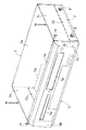
図1から図4は本考案の実施の一形態であるディスクプレーヤ一体型磁気テープ装置の
外装ケーシングを示すものであって、フロントパネル1の凹部1cの縦幅Hに比べてトッ
プケース3の各側板部突片5の縦幅hを小さく設定することにより、該各側板部突片5の
下面と凹部1cの底面6との間に形成された小間隔tの空隙7〔図10(a)参照〕とほ
ぼ同一高さtの左右一対の受台10が凹部1cの底面6の両端に一体形成されている。上
記以外の構成は図9及び図10に示す構成とほぼ同じであるので、同一部分に同一符号を
付してその説明を省略する。
FIGS. 1 to 4 show an outer casing of a magnetic tape apparatus integrated with a disk player according to an embodiment of the present invention. By setting the vertical width h of the side
上記構成によれば、外装ケーシングの組立時に、フロントパネル1の凹部1c内にトッ
プケース3の各側板部突片5を挿入すると、該各側板部突片5の下面が各受台10の上面
に当接または近接されるので、トップケース3をベースケース2にビス8で止着する際に
、作業員がトップケース3の天板部3aの両端部を不測に押圧Wしても、該トップケース
3の側板部3b,3cが押し下げられることがなく、そのトップケース3の天板部3aの
両端部とフロントパネル1の天板部1Aとの間に従来のように段差α(図9参照)が生じ
ることがない。
According to the above configuration, when each side
図5及び図6に示すように、トップケース3の天板部突片4の両端部近傍部分を下向き
直角に折り曲げて左右一対のL字片4aが形成される共に、その天板部突片4の両L字片
4a以外の部分を下向き円弧状に折り曲げてJ字片4bが形成され、図7(a)(d)に
示すように、フロントパネル1の天板部1Aの下面の両端部近傍から後方に延びる2つの
両端支持アーム11,12上のリブ11a,12aに形成した位置決め溝11b,12b
に前記各L字片4aの先端が嵌入され、図7(b)(c)に示すように、前記フロントパ
ネル1の天板部1Aの下面の中央部に所定間隔をおいて突設されて後方に延びる複数(こ
の実施の形態では3つ)の中央支持アーム13〜15上のリブ13a〜15aに前記J字
片4bが載置されている。
As shown in FIGS. 5 and 6, a pair of left and right L-shaped
The front ends of the L-shaped
上記構成によれば、2つの両端支持アーム11,12と複数の中央支持アーム13〜1
5とにより各L字片4a及びJ字片4bを介してトップケース3の天板部3aを支持して
いるので、そのトップケース3の天板部3aの上面を波打たないように一直線状に保持し
てフロントパネル1の天板部1Aの上面と面一状にすることができ、特に、前記各L字片
4aの先端を各両端支持アーム11,12の位置決め溝11b,12bに嵌入させている
ので、トップケース3の天板部3aとフロントパネル1の天板部1Aとの間に隙間が生じ
ないように体裁良く一体的につなぐことができる。
According to the above configuration, the two
5 supports the
図8(a)(b)に示すように、フロントパネル1の各側板部1B,1Cの内側面上下
端近傍から後方に延びる上下2つの側方支持アーム16,17上のリブ16a,17aに
形成したスリット16b,17bにトップケース3の各側板部突片5が挿入されている。
As shown in FIGS. 8A and 8B,
上記構成によれば、トップケース3の側板部3b,3cを波打たないように一直線状に
保持してフロントパネル1の側板部1B,1Cと面一状に体裁良くつなぐことができる。
According to the above configuration, the
以上要するに、ディスク挿入口1aとカセット挿入口1bとを並設した横幅が広いフロ
ントパネル1であっても、そのフロントパネル1にトップケース3を面一状につないで外
観上の体裁を良好に維持した商品価値の高いディスクプレーヤ一体型磁気テープ装置を提
供することができる。
In short, even with a wide
上記の実施の形態では、ディスクプレーヤ一体型磁気テープ装置を例にあげて説明した
が、これに限定されるわけではなく、例えば単体型ディスクプレーヤや単体型磁気テープ
装置などの各種電気機器の外装ケーシングにも適用される。
In the above-described embodiment, the magnetic tape device integrated with a disk player has been described as an example. However, the present invention is not limited to this. For example, the exterior of various electric devices such as a single disk player and a single magnetic tape device. Also applies to casings.
1 フロントパネル
1A フロントパネルの天板部
1B,1C フロントパネルの側板部
1a ディスク挿入口
1b カセット挿入口
1c フロントパネルの凹部
2 ベースケース
2b,2c ベースケースの側板部
3 トップケース
3a トップケースの天板部
3b,3c トップケースの側板部
4 天板部突片
4a L字片
4b J字片
5 側板部突片
6 凹部の底面
7 空隙
8 ビス
10 受台
11,12 両端支持アーム
11b,12b 位置決め溝
13〜15 中央支持アーム
16,17 側方支持アーム
16b,17b スリット
H 凹部の縦幅
h 側板部突片の縦幅
t 空隙の間隔
REFERENCE SIGNS
Claims (5)
した合成樹脂製フロントパネルを有し、該フロントパネルの後部に略コ字状金属板からな
るベースケースとトップケースとが配置されたものであって、前記トップケースの天板部
の前縁部を折り曲げて前方に突出する天板部突片と該トップケースの両側板部の前縁部を
折り曲げて前方に突出する一対の側板部突片とがそれぞれフロントパネルの凹部内に挿入
され、該凹部の縦幅に比べて各側板部突片の縦幅を小さく設定することにより、該各側板
部突片の下面と凹部の底面との間に小間隔の空隙が形成され、トップケースの各側板部と
それに重合するベースケースの各側板部とがビスにより止着されたディスクプレーヤ一体
型磁気テープ装置の外装ケーシングにおいて、前記空隙とほぼ同一高さの左右一対の受台
を前記凹部の底面両端に一体形成することにより、該各受台の上面に前記各側板部突片の
下面が当接または近接され、前記天板部突片の両端部近傍部分を下向き直角に折り曲げて
左右一対のL字片が形成される共に、その天板部突片の両L字片以外の部分を下向き円弧
状に折り曲げてJ字片が形成され、前記フロントパネルの天板部下面の両端部近傍から後
方に延びる2つの両端支持アームに形成した位置決め溝に前記各L字片の先端が嵌入され
ると共に、前記フロントパネルの天板部下面の中央部に所定間隔をおいて突設されて後方
に延びる複数の中央支持アーム上に前記J字片が載置され、前記フロントパネルの各側板
部の内側面上下端近傍から後方に延びる上下2つの側方支持アームに形成したスリットに
前記各側板部突片が挿入されていることを特徴とするディスクプレーヤ一体型磁気テープ
装置の外装ケーシング。 The front case has a synthetic resin front panel in which a disc insertion slot and a cassette insertion slot are arranged side by side and a concave portion is formed on the back surface, and a base case and a top case made of a substantially U-shaped metal plate are provided at the rear of the front panel. A top plate projecting piece that bends a front edge of a top plate of the top case and projects forward and a front edge of both side plates of the top case bends and projects forward. A pair of side plate protrusions are respectively inserted into the recesses of the front panel, and by setting the vertical width of each side plate protrusion to be smaller than the vertical width of the recess, the lower surface of each side plate protrusion is In the outer casing of the disk player integrated magnetic tape device in which a small gap is formed between the bottom surface of the concave portion and each side plate portion of the top case and each side plate portion of the base case overlapping with the top case are fixed by screws. ,Previous By forming a pair of left and right pedestals having substantially the same height as the gap at both ends of the bottom surface of the concave portion, the lower surfaces of the side plate projections abut or approach the upper surfaces of the respective pedestals. A pair of left and right L-shaped pieces are formed by bending the portions in the vicinity of both ends of the part protruding piece downwardly at a right angle, and a part other than the two L-shaped pieces of the top plate protruding piece is bent in a downward arc shape to form a J-shaped piece. Are formed, and the front ends of the L-shaped pieces are fitted into positioning grooves formed in two end support arms extending rearward from the vicinity of both ends of the lower surface of the top panel portion of the front panel. The J-shaped piece is mounted on a plurality of central support arms protruding rearward at predetermined intervals at a central portion of the lower surface of the front panel, and rearward from near the upper and lower ends of the inner side surface of each side plate portion of the front panel. Formed on the upper and lower side support arms Exterior casing of the disc player integrated magnetic tape unit, characterized in that said the slit each side plate protruding piece is inserted.
属板からなるベースケースとトップケースとが配置され、前記トップケースの天板部の前
縁部を折り曲げて前方に突出する天板部突片と該トップケースの両側板部の前縁部を折り
曲げて前方に突出する一対の側板部突片とがそれぞれフロントパネルの凹部内に挿入され
、トップケースの各側板部とそれに重合するベースケースの各側板部とがビスにより止着
された電気機器の外装ケーシングにおいて、凹部の縦幅に比べて各側板部突片の縦幅を小
さく設定することにより、該各側板部突片の下面と凹部の底面との間に小間隔の空隙が形
成され、該空隙とほぼ同一高さの左右一対の受台を前記凹部の底面両端に一体形成するこ
とにより、該各受台の上面に前記各側板部突片の下面が当接または近接されていることを
特徴とする電気機器の外装ケーシング。 A base case and a top case made of a substantially U-shaped metal plate are arranged at a rear portion of a synthetic resin front panel having a concave portion formed on the back surface, and a front edge of a top plate portion of the top case is bent and protruded forward. A pair of top plate protrusions and a pair of side plate protrusions that bend the front edges of both side plates of the top case and project forward are respectively inserted into the recesses of the front panel. In the outer casing of an electric device in which each side plate portion of the base case to be superimposed is fastened with a screw, by setting the vertical width of each side plate portion projecting piece smaller than the vertical width of the concave portion, each side plate portion projection is formed. A small gap is formed between the lower surface of the piece and the bottom surface of the concave portion, and a pair of left and right pedestals having substantially the same height as the gap are integrally formed at both ends of the bottom surface of the concave portion, so that On the top surface of each side plate projection Exterior casing of the electrical device, characterized in that the surface is in contact with or in proximity.
のL字片が形成される共に、その天板部突片の両L字片以外の部分を下向き円弧状に折り
曲げてJ字片が形成され、前記フロントパネルの天板部下面の両端部近傍から後方に延び
る2つの両端支持アームに形成した位置決め溝に前記各L字片の先端が嵌入されると共に
、前記フロントパネルの天板部下面の中央部に所定間隔をおいて突設されて後方に延びる
複数の中央支持アーム上に前記J字片が載置されていることを特徴とする請求項2に記載
の電気機器の外装ケーシング。 A pair of left and right L-shaped pieces is formed by bending the portions near both ends of the top plate projecting piece downward at right angles, and the other parts of the top plate projecting piece except for the two L-shaped pieces are bent in a downward arc shape. A J-shaped piece is formed, and the front end of each of the L-shaped pieces is fitted into a positioning groove formed in two end support arms extending rearward from near both ends of the lower surface of the top panel of the front panel. 3. The electric device according to claim 2, wherein the J-shaped piece is mounted on a plurality of central support arms protruding from a central portion of a lower surface of the top plate at a predetermined interval and extending rearward. 4. Outer casing of equipment.
上下2つの側方支持アームに形成したスリットに前記各側板部突片が挿入されていること
を特徴とする請求項2または3に記載の電気機器の外装ケーシング。 4. The side plate projecting piece is inserted into a slit formed in two upper and lower side support arms extending rearward from near the upper and lower ends of the inner surface of each side plate of the front panel. An outer casing for an electric device according to claim 1.
のディスク挿入口とカセット挿入口とが並設されていることを特徴とする請求項2から4
のいずれかに記載の電気機器の外装ケーシング。
5. A disk insertion slot and a cassette insertion slot of a disk player-integrated magnetic tape device are juxtaposed at the front of the front panel.
An outer casing for an electric device according to any one of the above.
Priority Applications (4)
| Application Number | Priority Date | Filing Date | Title |
|---|---|---|---|
| JP2003271469U JP3100734U (en) | 2003-09-29 | 2003-09-29 | External casing of magnetic tape device and electric equipment integrated with disk player |
| US10/950,432 US6903937B2 (en) | 2003-09-29 | 2004-09-28 | Outer casing of electric equipment |
| EP04023253A EP1519387B1 (en) | 2003-09-29 | 2004-09-29 | Outer casing of electric equipment |
| DE602004029125T DE602004029125D1 (en) | 2003-09-29 | 2004-09-29 | Serving of electrical appliance |
Applications Claiming Priority (1)
| Application Number | Priority Date | Filing Date | Title |
|---|---|---|---|
| JP2003271469U JP3100734U (en) | 2003-09-29 | 2003-09-29 | External casing of magnetic tape device and electric equipment integrated with disk player |
Publications (1)
| Publication Number | Publication Date |
|---|---|
| JP3100734U true JP3100734U (en) | 2004-05-27 |
Family
ID=34631335
Family Applications (1)
| Application Number | Title | Priority Date | Filing Date |
|---|---|---|---|
| JP2003271469U Expired - Fee Related JP3100734U (en) | 2003-09-29 | 2003-09-29 | External casing of magnetic tape device and electric equipment integrated with disk player |
Country Status (4)
| Country | Link |
|---|---|
| US (1) | US6903937B2 (en) |
| EP (1) | EP1519387B1 (en) |
| JP (1) | JP3100734U (en) |
| DE (1) | DE602004029125D1 (en) |
Cited By (1)
| Publication number | Priority date | Publication date | Assignee | Title |
|---|---|---|---|---|
| JP2011096303A (en) * | 2009-10-28 | 2011-05-12 | Funai Electric Co Ltd | Dustproof and soundproof structure of electric equipment |
Families Citing this family (10)
| Publication number | Priority date | Publication date | Assignee | Title |
|---|---|---|---|---|
| US20050018408A1 (en) * | 2003-07-24 | 2005-01-27 | Rivkin David Aaron | Multiple mounting, self aligning, electronics enclosure (multimount) |
| JP4009960B2 (en) * | 2004-04-05 | 2007-11-21 | 船井電機株式会社 | Front panel mating device |
| JP2006156501A (en) * | 2004-11-25 | 2006-06-15 | Orion Denki Kk | Electronic apparatus equipped with housing |
| JP2006286036A (en) * | 2005-03-31 | 2006-10-19 | Orion Denki Kk | Recording and reproducing apparatus |
| JP2007184473A (en) * | 2006-01-10 | 2007-07-19 | Funai Electric Co Ltd | Electric equipment cabinet |
| JP3128387U (en) * | 2006-10-25 | 2007-01-11 | 船井電機株式会社 | Power supply circuit structure of electrical equipment |
| CN103108511A (en) * | 2011-11-09 | 2013-05-15 | 鸿富锦精密工业(深圳)有限公司 | Electronic device |
| CN103429033B (en) * | 2012-05-22 | 2016-12-14 | 纬创资通股份有限公司 | Have and assemble the cover plate of positioning function and there is the electronic installation assembling positioning function |
| US10823210B2 (en) * | 2017-05-17 | 2020-11-03 | Andrew Wireless Systems Gmbh | Self-locking front panel |
| FR3076094B1 (en) * | 2017-12-22 | 2020-01-10 | Valeo Siemens Eautomotive France Sas | HOUSING ELEMENT OF AN ELECTRICAL EQUIPMENT, PARTICULARLY INCLUDING MAGNETIC PIECES IN ‘U’ |
Family Cites Families (17)
| Publication number | Priority date | Publication date | Assignee | Title |
|---|---|---|---|---|
| US4940976A (en) * | 1988-02-05 | 1990-07-10 | Utilicom Inc. | Automated remote water meter readout system |
| JPH0231497A (en) * | 1988-07-20 | 1990-02-01 | Fujitsu General Ltd | Mounting structure of cabinet |
| US5252967A (en) * | 1990-05-25 | 1993-10-12 | Schlumberger Industries, Inc. | Reader/programmer for two and three wire utility data communications system |
| KR960001787Y1 (en) * | 1993-10-04 | 1996-02-24 | 삼성전자 주식회사 | Computer accessory coupling device |
| JPH06283869A (en) * | 1993-03-26 | 1994-10-07 | Hitachi Ltd | Cabinet device |
| US5617084A (en) * | 1993-09-10 | 1997-04-01 | Sears; Lawrence M. | Apparatus for communicating utility usage-related information from a utility usage location to a utility usage registering device |
| US6323774B1 (en) * | 1995-09-13 | 2001-11-27 | Gregory L. Mitchell | Portable excess water usage control and alarm system |
| JPH1021677A (en) * | 1996-07-02 | 1998-01-23 | Mitsumi Electric Co Ltd | Disc drive |
| DE69612747T2 (en) * | 1996-10-03 | 2001-08-23 | Hewlett Packard Co | Mounting arrangement for fastening a system unit |
| US6377190B1 (en) * | 1996-11-08 | 2002-04-23 | David A. Saar | System for monitoring water consuming structures in an individual unit of a multi-unit building |
| DE29705507U1 (en) * | 1997-03-26 | 1997-05-15 | Siemens Nixdorf Inf Syst | Holders for computer storage drives |
| JPH11144444A (en) | 1997-11-04 | 1999-05-28 | Ricoh Co Ltd | Recording disk drive unit |
| TW495056U (en) * | 2000-02-02 | 2002-07-11 | Hon Hai Prec Ind Co Ltd | Fixture apparatus of data access device |
| US6373695B1 (en) * | 2000-09-22 | 2002-04-16 | Mace Tech Corp. | Mobile rack mounting structure for computer |
| TW487282U (en) * | 2000-12-22 | 2002-05-11 | Aopen Inc | Securing structure for computer storage medium |
| US6819292B2 (en) * | 2001-03-09 | 2004-11-16 | Arad Measuring Technologies Ltd | Meter register |
| US6556142B2 (en) * | 2001-09-20 | 2003-04-29 | Intel Corporation | System and method to communicate flow information between a service distribution line and a destination point |
-
2003
- 2003-09-29 JP JP2003271469U patent/JP3100734U/en not_active Expired - Fee Related
-
2004
- 2004-09-28 US US10/950,432 patent/US6903937B2/en not_active Expired - Fee Related
- 2004-09-29 EP EP04023253A patent/EP1519387B1/en not_active Expired - Fee Related
- 2004-09-29 DE DE602004029125T patent/DE602004029125D1/en active Active
Cited By (1)
| Publication number | Priority date | Publication date | Assignee | Title |
|---|---|---|---|---|
| JP2011096303A (en) * | 2009-10-28 | 2011-05-12 | Funai Electric Co Ltd | Dustproof and soundproof structure of electric equipment |
Also Published As
| Publication number | Publication date |
|---|---|
| EP1519387A3 (en) | 2005-12-07 |
| EP1519387B1 (en) | 2010-09-15 |
| US20050068749A1 (en) | 2005-03-31 |
| EP1519387A2 (en) | 2005-03-30 |
| DE602004029125D1 (en) | 2010-10-28 |
| US6903937B2 (en) | 2005-06-07 |
Similar Documents
| Publication | Publication Date | Title |
|---|---|---|
| JP3100734U (en) | External casing of magnetic tape device and electric equipment integrated with disk player | |
| JP3084222B2 (en) | PC card frame kit and PC card | |
| TW201345377A (en) | Expansion module and fixing frame thereof | |
| JP2000182694A (en) | Connector for circuit board connection | |
| JPH0717175Y2 (en) | Case fixing device | |
| JP3265795B2 (en) | Electrical connector | |
| US20070177337A1 (en) | Electronic device | |
| JP2013040671A (en) | Plate material coupling structure | |
| JPH07220816A (en) | Electric connector | |
| JP3076702B2 (en) | Display element holding device | |
| JP2010020928A (en) | Fpc connector | |
| JP3062621B2 (en) | Lead wire connection device for large current | |
| JP4690578B2 (en) | Electronic equipment ground pattern connection bracket and board mounting structure | |
| JP3086748U (en) | Electronic equipment having antistatic mechanism | |
| JP3090710U (en) | Earphone jack holding device | |
| JP3107373U (en) | Electrical equipment housing | |
| JP6784393B2 (en) | connector | |
| WO2013051073A1 (en) | Electronic device case | |
| JP2858212B2 (en) | Slide switch | |
| JP4682961B2 (en) | Board mounting structure for electronic equipment | |
| JPH0719982B2 (en) | Case mounting device | |
| JP2002285675A (en) | Connection mechanism of hanging rod for ceiling board | |
| KR100797023B1 (en) | Top knob apparatus of an electronic appliance | |
| JP2858216B2 (en) | Slide switch | |
| JP3020962U (en) | Insulation structure of electronic equipment |
Legal Events
| Date | Code | Title | Description |
|---|---|---|---|
| R250 | Receipt of annual fees |
Free format text: JAPANESE INTERMEDIATE CODE: R250 |
|
| FPAY | Renewal fee payment (event date is renewal date of database) |
Free format text: PAYMENT UNTIL: 20080121 Year of fee payment: 4 |
|
| FPAY | Renewal fee payment (event date is renewal date of database) |
Free format text: PAYMENT UNTIL: 20090121 Year of fee payment: 5 |
|
| LAPS | Cancellation because of no payment of annual fees |