EP1701178B1 - Method and system for preventing an aircraft from penetrating into a dangerous trailing vortex area of a vortex generator - Google Patents
Method and system for preventing an aircraft from penetrating into a dangerous trailing vortex area of a vortex generator Download PDFInfo
- Publication number
- EP1701178B1 EP1701178B1 EP03817670A EP03817670A EP1701178B1 EP 1701178 B1 EP1701178 B1 EP 1701178B1 EP 03817670 A EP03817670 A EP 03817670A EP 03817670 A EP03817670 A EP 03817670A EP 1701178 B1 EP1701178 B1 EP 1701178B1
- Authority
- EP
- European Patent Office
- Prior art keywords
- vortex
- aircraft
- coordinates
- trailing
- area
- Prior art date
- Legal status (The legal status is an assumption and is not a legal conclusion. Google has not performed a legal analysis and makes no representation as to the accuracy of the status listed.)
- Expired - Lifetime
Links
- 238000000034 method Methods 0.000 title claims abstract description 38
- 230000000149 penetrating effect Effects 0.000 title 1
- 230000035515 penetration Effects 0.000 claims abstract 2
- 230000033001 locomotion Effects 0.000 claims description 53
- 230000007613 environmental effect Effects 0.000 claims description 14
- 230000008859 change Effects 0.000 claims description 13
- 238000012937 correction Methods 0.000 claims description 11
- 238000012544 monitoring process Methods 0.000 claims description 11
- 230000001939 inductive effect Effects 0.000 claims description 9
- 230000000007 visual effect Effects 0.000 claims description 8
- 238000004088 simulation Methods 0.000 claims description 6
- 238000012360 testing method Methods 0.000 claims description 6
- 230000007704 transition Effects 0.000 claims description 5
- 230000005540 biological transmission Effects 0.000 claims description 2
- 230000005055 memory storage Effects 0.000 claims 3
- 238000012216 screening Methods 0.000 claims 2
- 238000012800 visualization Methods 0.000 abstract description 8
- 230000002265 prevention Effects 0.000 abstract description 3
- 230000005484 gravity Effects 0.000 description 19
- 238000012806 monitoring device Methods 0.000 description 11
- 230000000694 effects Effects 0.000 description 7
- 238000004364 calculation method Methods 0.000 description 6
- 238000011161 development Methods 0.000 description 5
- 230000018109 developmental process Effects 0.000 description 5
- 238000010586 diagram Methods 0.000 description 5
- 231100001261 hazardous Toxicity 0.000 description 5
- 230000001965 increasing effect Effects 0.000 description 5
- 230000009471 action Effects 0.000 description 4
- 230000032683 aging Effects 0.000 description 3
- 230000006399 behavior Effects 0.000 description 3
- 238000004422 calculation algorithm Methods 0.000 description 3
- 238000011156 evaluation Methods 0.000 description 3
- 230000008569 process Effects 0.000 description 3
- 238000010276 construction Methods 0.000 description 2
- 238000001514 detection method Methods 0.000 description 2
- 230000002996 emotional effect Effects 0.000 description 2
- 238000003384 imaging method Methods 0.000 description 2
- 230000006872 improvement Effects 0.000 description 2
- 238000012797 qualification Methods 0.000 description 2
- 230000001105 regulatory effect Effects 0.000 description 2
- 230000035882 stress Effects 0.000 description 2
- 238000012549 training Methods 0.000 description 2
- 230000001133 acceleration Effects 0.000 description 1
- 239000008186 active pharmaceutical agent Substances 0.000 description 1
- 230000006978 adaptation Effects 0.000 description 1
- 238000013459 approach Methods 0.000 description 1
- 230000008901 benefit Effects 0.000 description 1
- 239000000969 carrier Substances 0.000 description 1
- 230000003727 cerebral blood flow Effects 0.000 description 1
- 239000003795 chemical substances by application Substances 0.000 description 1
- 230000001447 compensatory effect Effects 0.000 description 1
- 230000008094 contradictory effect Effects 0.000 description 1
- 230000001419 dependent effect Effects 0.000 description 1
- 238000013461 design Methods 0.000 description 1
- 239000003989 dielectric material Substances 0.000 description 1
- 230000006870 function Effects 0.000 description 1
- 230000007274 generation of a signal involved in cell-cell signaling Effects 0.000 description 1
- 230000003993 interaction Effects 0.000 description 1
- 230000014759 maintenance of location Effects 0.000 description 1
- 238000005259 measurement Methods 0.000 description 1
- 230000015654 memory Effects 0.000 description 1
- 210000000056 organ Anatomy 0.000 description 1
- 230000002085 persistent effect Effects 0.000 description 1
- 238000007781 pre-processing Methods 0.000 description 1
- 230000009467 reduction Effects 0.000 description 1
- 238000011160 research Methods 0.000 description 1
- 238000004904 shortening Methods 0.000 description 1
- 238000013517 stratification Methods 0.000 description 1
- 230000000699 topical effect Effects 0.000 description 1
- 238000012546 transfer Methods 0.000 description 1
- 238000007794 visualization technique Methods 0.000 description 1
Images
Classifications
-
- G—PHYSICS
- G01—MEASURING; TESTING
- G01C—MEASURING DISTANCES, LEVELS OR BEARINGS; SURVEYING; NAVIGATION; GYROSCOPIC INSTRUMENTS; PHOTOGRAMMETRY OR VIDEOGRAMMETRY
- G01C23/00—Combined instruments indicating more than one navigational value, e.g. for aircraft; Combined measuring devices for measuring two or more variables of movement, e.g. distance, speed or acceleration
- G01C23/005—Flight directors
-
- G—PHYSICS
- G01—MEASURING; TESTING
- G01S—RADIO DIRECTION-FINDING; RADIO NAVIGATION; DETERMINING DISTANCE OR VELOCITY BY USE OF RADIO WAVES; LOCATING OR PRESENCE-DETECTING BY USE OF THE REFLECTION OR RERADIATION OF RADIO WAVES; ANALOGOUS ARRANGEMENTS USING OTHER WAVES
- G01S13/00—Systems using the reflection or reradiation of radio waves, e.g. radar systems; Analogous systems using reflection or reradiation of waves whose nature or wavelength is irrelevant or unspecified
- G01S13/88—Radar or analogous systems specially adapted for specific applications
- G01S13/93—Radar or analogous systems specially adapted for specific applications for anti-collision purposes
- G01S13/933—Radar or analogous systems specially adapted for specific applications for anti-collision purposes of aircraft or spacecraft
-
- G—PHYSICS
- G05—CONTROLLING; REGULATING
- G05D—SYSTEMS FOR CONTROLLING OR REGULATING NON-ELECTRIC VARIABLES
- G05D1/00—Control of position, course, altitude or attitude of land, water, air or space vehicles, e.g. using automatic pilots
- G05D1/10—Simultaneous control of position or course in three dimensions
- G05D1/101—Simultaneous control of position or course in three dimensions specially adapted for aircraft
- G05D1/104—Simultaneous control of position or course in three dimensions specially adapted for aircraft involving a plurality of aircrafts, e.g. formation flying
Definitions
- the invention belongs to methods and devices of aviation safety, in particular to methods for the prevention of extraordinary situations, with a possible entry of aircraft into a wake turbulence zone of a vortex generator, u. a. at the outlet of an object, are connected.
- the problem of aviation safety is very topical and covers a whole range of both scientific-technical and methodological organizational tasks.
- One of these objects is to ensure flight safety in the situation where the flight safety factor is the effect of the aerodynamic air flow of high turbulence on an aircraft, wherein the air flow both in the movement of the power generating object in the vicinity of an aircraft and in the presence of with Currents higher Turbulence and turbulence surrounding objects can be generated in the environment of an aircraft.
- the entry of the aircraft into the wake of another object leads to a substantial change in the angle of attack (angle of attack) and the angle of flight.
- the aircraft is exposed to the effect of aerodynamic forces and moments that move it, for example, laterally from the train and at lower altitudes, for example when starting or landing, because of the impossible compensation of this effect by means of control organs of the aircraft can lead to extraordinary situations.
- Another task which can be counted among the information tasks is the provision of information about the position of the wake and the aircraft at the predicted time.
- a method and apparatus for optically imaging wake vortices by means of mathematical wake turbulence models based on flight parameters of the vortex generating aircraft, taking into account the effect of atmospheric conditions on wake turbulence are known.
- a fast-acting display is used, in which a visualization of simulated wake turbulences of individual aircraft is carried out, which are located in the vicinity of said aircraft.
- the display maps a large number of the simulated wake vortices, thereby creating difficulties in determining the wake vortices that present an actual danger to the aircraft in determining the danger that can be neglected.
- this system does not provide any information on the potential risk of entry into the detected wake turbulence and the appropriate maneuver of the aircraft to exclude the entry into the wake turbulence.
- a wake turbocharging system equipped with each aircraft is known to warn the pilot of the predictive, dangerous presence of an aircraft flying in front of another nearby aircraft.
- the system includes a spherical Dielectric material antenna and eight sectors with receivers for receiving microwave signals reflected from other aircraft in the vicinity.
- the system is expensive and does not provide the pilot with any information about the dangerous currents.
- a technical solution which relates to methods for avoiding the overlap of the aircraft path with the wake of another aircraft.
- This solution includes determining the position, configuration and type of vortices caused by the other aircraft, the presence of which is determined using information from onboard systems of the first aircraft, information from the other aircraft or information from the airport, and a determination of Aircraft altitude, the prediction position of the wake turbulence generated by the aircraft using atmospheric conditions, in particular the wind speed and direction and the air temperature, an evaluation of the received data with respect to reference tables or a simulation of the wake with the visualization of the wake position and trajectory with respect to the first Aircraft and a forecast of the point of intersection of the wake turbulence with the movement of the first aircraft with a warning signal generation in the event of such an overlap.
- the method of flight safety of two aircraft in the terminal area is used, and its implementation may lead to a transfer of the trajectory of the first aircraft to a greater height to the second aircraft. It uses the Traffic Collision Avoidance System. However, for the pilot of the first aircraft, information is displayed on all vortex ranges predicted in the vicinity of the first aircraft with respect to the second aircraft, whereby no actual hazard image of these vortexes for the flight of the second aircraft is provided.
- AVOSS wake turbocharging
- the behavior of the wake turbulence is compared with predetermined sizes of the safety corridor and the determination of wake turbulence, and thus the desired staggering of the aircraft is determined. If the wake turbulence lasts longer than expected, shortening the safety margin between take-off or landing is prohibited.
- the behavior of the wake turbulence is calculated by a plurality of "windows" of the landing approach from the Gleitwegière to the front side of the runway.
- this known system is limited in that a vertical wind shift is not detected, which can prevent a decrease in the wake turbulence or lead to an increase in the wake turbulence; furthermore, the concrete amount of turbulence required to simulate drag aging is not detected; furthermore, there are other limitations that can lead to an extraordinary situation due to the non-conformity of the pre-calculated drag parameters with the actual parameters of the wake turbulence.
- VOSS system will increase the burden on air traffic controllers, who are in any case subject to high levels of emotional stress in the background of a substantial increase in their work, which is undesirable because it increases the possibility of inappropriate decisions.
- the effect of acceleration leads to a disturbance of the cerebral blood flow in the pilot and can lead to short-term consciousnesslessness in the case of emotional overexertion. Therefore, it is preferable to provide the pilot or air traffic controller with the required information before the decision meeting and in graphic symbols.
- the object of the invention is the development of a system for warning against a possible entry of an aircraft into a wake hazardous zone generated by other aircraft, above-ground objects, mobile and non-moving sea objects located in the vicinity of the flying aircraft, in particular at take-off and Landing, are located.
- above-ground objects mobile and non-moving sea objects located in the vicinity of the flying aircraft, in particular at take-off and Landing.
- not only airplanes but also above-ground and above-sea objects are considered as vortex generators, whose wake turbulence can be dangerous for an aircraft.
- the totality of the spatial points in which the aircraft flies in and in which it is exposed to forces and moments is called the wake turbulence hazard zone.
- the aim has been set to develop a method and a warning device which warn of the possible entry into a zone that is dangerous for the aircraft in terms of its construction and flight conditions, and the availability of information on the presence of wake vortices in the aircraft environment, which pose a danger to the aircraft, about its propagation and eventual avoidance of wake turbulence by means of a determination of the forecasting aircraft and wake turbulence position in a certain section in front of the aircraft along its course at a distance in which the aircraft may enter Ensure evasive maneuvers. It makes sense to determine the wake turbulence position taking into account the change of environmental parameters and a determination of the aircraft position, taking into account the aircraft configuration and of regulated flight execution standards.
- the aircraft configuration is, for example, a change in the engine operation, including a failure of one or more engines, a change in aircraft geometry, such as the wing arrow shape or icing of the aircraft surface, and other changes to understand that change the flow around the reverse flow, thus changing aerodynamic forces and moments caused by the action of aerodynamic currents, including wake turbulence, and changing the compensatory ability of these actions by the aircraft.
- the invention has also set itself the task of developing a device for carrying out the warning method.
- the user In carrying out the method according to the invention in order to warn against possible entry into the wake turbulence zone, the user is provided only with information about the wake vortices which is sufficient for him to carry out an effective maneuver avoiding entry into the wake ,
- the wake turbulence information realized in the invention it is possible to shorten the amount of information induced, leaving only the required information part.
- an adequate uptake of the aircraft spatial position with respect to wake turbulence at the forecasting time by the user, for example the pilot is ensured, whereby it is possible to take timely measures to prevent entry into the To hit the wake.
- the advantage of the method is that detection of the forces and moments acting on the aircraft caused by the change of the aircraft configuration is possible, because an adaptation of the method to the external conditions, the flight characteristics and the operation of the aircraft systems is guaranteed.
- the method according to the invention makes sense to constantly correct the selected lead time, which makes it possible to take into account specific flight conditions and flight tasks.
- the method according to the invention makes sense to continuously correct the coordinates of the center of gravity area, whereby it is possible to correct the time to decide on an evasive maneuver.
- the invention it is useful to store the information on the selected lead time, coordinates of the control area, the range of the forecasting aircraft positions and the wake turbulence zones in the course of the zero distance indication of the range of forecasting aircraft positions to the wake turbulent endangerment zone.
- the warning system comprises: a vortex generator monitoring device, a storage device, a wake monitoring device, a device for determining the parameters of the hazardous zone, a forecasting device, a computing device of the overlap points, a device for creating zones and areas Transitional block, two check blocks of the overlap condition and a display device and alarm indicators, these devices ensure a simultaneous operation in relation to each individual, located in the vicinity of the aircraft vortex generator.
- the advancing time selecting means be executed with the possibility of continuously updating the advancing time.
- the means for creating zones and areas be carried out with the possibility of continuously correcting the coordinates of the area of the forecasting aircraft positions.
- the means for creating zones and areas be executed with the possibility of continuously correcting the coordinates of the center of gravity.
- the current correction of the lead time, the coordinates of the range of the forecasting aircraft positions and the center of gravity can be set manually or semi-automatically.
- This embodiment of the warning system devices ensures flexibility of use of these devices both in hand steering the aircraft and using the automatic steering system.
- the warning system comprises a device for visualizing the information about the area of the forecasting aircraft positions and the wake turbulence zones located in the control area.
- the display device and the alarm display device may be selected from the group including visual display, audio display and button display devices.
- Such an embodiment of the warning system according to the invention using the device for determining the hazard zone parameters makes it possible to take into account peculiarities of the configuration and the flight conditions as well as the pilot qualification in the risk criterion selection.
- a permissible heeling value of the aircraft can be selected as the risk criterion.
- a permissible value of the vortex-inducing heeling moment can be selected as the hazard criterion.
- the block for the determination of the geometric characteristics of the wake turbulence zone can adjust the hazard threshold, whereby the visualization of the wake turbulence hazard zone in the visualization device is simplified.
- the wake vortex monitoring device and the prediction device according to the invention contain a programmable component, and the device for determining the hazard zone parameters is executed in the software of the programmable component.
- the hazard zone parameter determination device may include a database containing the characteristics of wake turbulence hazard zones of different types of turbulizers under different flight conditions.
- warning system may include storage means of the lead time information, coordinates of the control area, the range of the forecasting aircraft positions and the wake turbulence zones during the alarm indication of the zero distance of the range of forecasting aircraft positions to the wake turbulent endangerment zone.
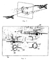
- Fig. 1 an embodiment of a warning system is shown, which is carried out as a basic equipment in the aircraft; the vortex generator is another aircraft and the user of the information is the crew of the aircraft.
- the description uses concrete terms. However, it must be remembered that each term encompasses all equivalent terms used in solving similar tasks.
- a number of information about the spatial position of the aircraft at the forecasting time in the calculated lead spacing in front of the aircraft in the control area and the possible position of the wake turbulence around the aircraft that pose a danger is corrected taking into account the environmental conditions at the location of the control surface.
- a monitoring device 1 of the aircraft parameters which is arranged for example in the computer of the automatic steering system of the aircraft, for example, from the aircraft navigation system information about the configuration, coordinates, movement and angular velocity of the aircraft, tamping, wind and Heel angle at the current time t in Inertialkoordinatensystem ( ICS).
- ICS Inertialkoordinatensystem
- a vortex generator monitoring device 2 which is arranged for example in the computer of the automatic steering system of the aircraft, receives information about the vortex generator type, its motion and angular velocity and the coordinates of the track points of the vortex generator in the ICS, for example, from the onboard radar, forward much radar, the air traffic controller or by an "Information Exchange Multiplex Channel", and a storage device 3 stores this information.
- an environmental parameter detector 4 located in the computer of the aircraft automatic steering system receives data on the strength and direction of the local wind speed, the wind profile on altitude, the degree of turbulence, and the type of shielding area in the common area, for example from the air data system or the air traffic controller of the aircraft and turbulizer in the ICS at the current time t .
- a wake monitoring device 5 which is arranged, for example, in the computer of the automatic steering system of the aircraft, calculates the wake vortex trajectory and intensity as the orbital mass of the centers of vortex regions in the ICS, for example by means of a known algorithm for calculating the wake vortex trajectory and intensity ( Northwest Research Associates, Inc., Aircraft Vortex Spacing System [AVOSS], Algorithm Version 3.1.1), which describes the calculation of the coordinates of the vortex centers by integrating a differential equation, propagation of the vortex fields in space and in time.
- a memory device 6 stores this data.
- the parameters of the coordinates of vortex regions can also be determined metrologically, for example by means of a lidar, by means of a measurement and evaluation of the tangential velocity of the air flow with subsequent calculation of the vortex trajectory and intensity.
- An example arranged in the computer of the automatic steering system of the aircraft selector 7 of the retention time calculates the time required for the maneuver of the flight path change lead time.
- the selected derivative time can be corrected according to the invention, taking into account, for example, the pilot qualification or the peculiarities of the flight task during operation by hand, semi or fully automatic.
- a simulation device 8 of the control surface calculates, from data about the coordinates, movement speed, tamping, wind and heeling angles of the aircraft from the device 7 and data over the selected lead time from the device 7, the lead spacing which is equal to the distance flown in the lead time, simulates a control area that lies in the space in front of the aircraft and perpendicular to its direction of movement at the calculated distance to the aircraft, for example in the form of factors of the area equation of the control area in the ICS, and determines the predicted time t + ⁇ t of the overlap of the control area in the ICS.
- each computing device that enables such calculations for example an on-board computer, can be used.
- a prediction device 9 calculates the coordinates of the wake trajectory and intensity from the device 6 stored data on the wake vortex trajectory and intensity as well as the projected time from the device 7 as a web totality of the centers of vortex regions in the forecasting time t + ⁇ t in the ICS.
- a device 10 for parameter determination of the hazard zone determines from data about the coordinates, movement and angular velocity of the aircraft from the device 1 and from data on the coordinates of the points of the wake vortex trajectory and intensity as web aggregate of the centers of vortex regions from the storage device 6, the geometric characteristic of the vortex hazard zone as a whole of vortex hazard zones in the forecasting time t + ⁇ t in accordance with the selected hazard criteria.
- the permissible heeling angle of the aircraft or the eddy-inducing, permissible heeling moment can be selected as risk criteria.
- the wake vortex monitoring device 5 and the forecasting device 9 may include a programmable component, here the vortex trajectory and intensity, and the device 10 may be implemented in the software of that component, for example in the database of calculated geometric characteristics of vortex hazard zones of different types of generators depending on different environmental conditions and motion parameters of the vortex generator, aerodynamic forces and moments, for example, heeling moments induced by wake vortices of different intensity.
- a programmable component here the vortex trajectory and intensity
- the device 10 may be implemented in the software of that component, for example in the database of calculated geometric characteristics of vortex hazard zones of different types of generators depending on different environmental conditions and motion parameters of the vortex generator, aerodynamic forces and moments, for example, heeling moments induced by wake vortices of different intensity.
- a device 11 ( Fig. 2 ), which is arranged for example in the computer of the navigation system on board, calculated from data on the coordinates of the control surface, the coordinates of the intersection points of the wake turbulence with the control surface at the forecasting time t + ⁇ t from the device 8 and from the data via the vortex trajectory from the device 9 by means of a selection of the points of the vortex trajectory lying on the two sides of the control surface with interpolation of the distance between them.
- a device 12 for creating zones and areas for example as a computer component of the navigation inertial system on board the aircraft, creates a vortex hazard zone, a region of the forecasting aircraft positions, around the point of intersection of the wake vortex path with the control surface using controlled flight execution standards at the predicted time t + At and a center of gravity as the sum of the points on the control area.
- the means 12 make it possible to carry out a continuous correction of the coordinates of the area of the forecasting aircraft positions and of the center of gravity, which is important for the pilot in the coordination of the avoidance maneuver and the flight task.
- a transition block 13 calculates the coordinates of the area of the forecasting aircraft positions, the vortex hazard zone, and the centroid area in the coordinate system coupled to the aircraft.
- a first test block 14 of intersection conditions calculates the distance from the centroid zone to the vortex zone, with zero spacing monitored, and a second block 15 calculates the distance from the range of forecasting aircraft locations to the vortex zone, with zero spacing monitored.
- Data on the zero distance at the predicted time are transmitted in display devices 16, 17, for example in the cockpit, in the device 16 for audio display when the distance between the center of gravity and the vortex zone is zero, and thereafter, for example, in the device 17 for key alarm display when the Distance between the range of forecasting aircraft positions and the vortex hazard zone is zero.
- the button display is to cause the pilot to take urgent action to perform an evasive maneuver in front of the hazard zone.
- the pilot has time to maneuver, which is specified by the pilot using the speed of movement of the aircraft.
- the lead time may be corrected by the pilot after the first display, for example, manually by setting a number parameter of the lead time or by automatically setting the time increase or decrease condition.
- the display stops which confirms the avoidance of the aircraft from the dangerous situation and facilitates the effort of the user.
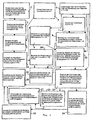
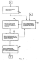
- the device 10 for determining the hazard zone parameters can be executed according to the invention and, as shown in the block diagram of FIG Fig. 3 a block diagram 20 of information from the block 19 and from the device 6 of the warning system can be seen, a block 20 of known design, which receives information from the device 1 of the warning system and calculates the totality of geometric aircraft characteristics with the detection of the configuration of the aircraft ( Fig. 2 ) and determines the vortex-inducing additional forces and moments in the space point.
- a block 21 determines the endangerment of the air flow in the given point of space on the basis of a given risk criterion
- a block 22 determines the space points belonging to the vortex hazard zone
- a block 23 determines the geometric characteristic of the hazard zone as a whole of the points and adjusts the hazard threshold to simplify the hazard zone visualization to the display.
- the data on the parameters of the hazardous zone are then transmitted to the device 8 of the warning system and displayed in case of danger of entry of the aircraft into the vortex zone.
- Fig. 4 is a display of the location map shown, which is used in the aircraft for course and symbol display, which are generated by the navigation inertial system, such as Airborne Inertial Navigation System (AINS) with the Representation of a region 25 of the forecasting aircraft positions and vortex hazard zones 26, 27 in the room at the forecasting time.
- the area 25 may be in the form of a rectangle whose size is proportional to the dimensions of the area of a possible aircraft position in space.
- the boundaries of the center of gravity are not shown on the display, since it makes sense according to the invention that the image of vortex hazard zones with a simultaneous display, such as an audio display, are only displayed on the display when the vulnerable zones overlap the center of gravity.
- the hazard zones 26, 27 may be in the shape of a circle or other geometric figure for convenient visual recording.
- the image with visual display of the regions 25, 26, 27 or their boundaries 29, 30, 31 can be accompanied, for example, by a light or color display if the boundary 29 of the region 25 intersects with the region boundary, for example the danger zone 26 , This fact is accompanied by an audio or button alarm display.
- vortex generators Although only one of the vortex generators is shown in the example described and the behavior of only one vortex hazard zone is visualized and induced, naturally all vortex generators located in the space surrounding the aircraft are detected and the wake turbulences of these vortex generators are metrologically monitored and only those wake vortex hazard zones are depicted on the display that pose a potential hazard to the aircraft. In this case, the pilot can make an appropriate decision on the aircraft maneuver due to the evaluation of the schematically depicted position of potential hazard zones in order to avoid the vortex hazard zones.
- the invention it is useful to keep the current data on the selected lead time, coordinates of the control area, the range of forecasting aircraft positions and vortex hazard zones in the course of the alarm display of the Saving zero distance from the range of predicted aircraft positions to the vortex hazard zone, for example, in the flight recorder, thereby allowing to determine the causes of an aircraft crash to assess pilot actions in the situation where the entry into the wake turbulence zone, for example, led to a change in aircraft configuration or trajectory.
- the warning subsystem 4 of the possible entry into the vortex hazard zone can be carried out according to the invention with the aid of the on-board and ground-based basic equipment, for example the Airborne Inertial Navigation System (AINS), the Air Data Computer System (ADC), Doppler Slide Speedometer (Doppler System / DS), Forward View Radar (FVR) and using data obtained from Air Traffic Control (ATC), the United Indication System (UIS), the multiplex channel of data exchange (Information Exchange Multiplex Channel / IEMC) as well as data from the systems which are compatible with said information systems and used in other foreign aircraft, for example in the American systems Collision Avoidance System (TCAS) and Traffic Alert.
- AINS Airborne Inertial Navigation System
- ADC Air Data Computer System
- Doppler Slide Speedometer Doppler System / DS
- FVR Forward View Radar
- ATC Air Traffic Control
- UAS United Indication System
- IEMC Information Exchange Multiplex Channel / IEMC
- TCAS American systems Collision Avoidance System
- the devices of the integrated system according to the invention may be arranged in different objects of the air traffic control system or the aircraft and the vortex generator, wherein the user obtains information about the results of the calculations by means of a display and visualization.
- both the crew of an aircraft and pilots of an airport or a ship can advise the crew on the recommended trajectory or on the required maneuver of the aircraft to avoid dangerous situations.
- the warning system according to the invention for the flight and roll control can be used, since the monitoring of the vortex situation in the environment of landed vortex generators and vortex generators in flight can be carried out by means of warning systems independently on board , arranged on a ship or in airports and are part of the unitary system that avoids the extraordinary situation of entry into the vortex zone.
- a turbulizer aircraft of different types such as aircraft, helicopters, unmanned aircraft, seagoing vessels, including aircraft carriers, as well as ground facilities and other objects.
- the warning system against possible entry of an aircraft into a wake hazard zone may usefully be implemented as software which can be adapted to the type of aircraft, its flight conditions and the type of equipment used on board and compatible with the air traffic control information systems is.
- the warning system according to the invention can be easily implemented using existing computing devices and used for construction in different aircraft and training equipment for pilot and pilot training.
Landscapes
- Engineering & Computer Science (AREA)
- Radar, Positioning & Navigation (AREA)
- Remote Sensing (AREA)
- Physics & Mathematics (AREA)
- Aviation & Aerospace Engineering (AREA)
- General Physics & Mathematics (AREA)
- Computer Networks & Wireless Communication (AREA)
- Electromagnetism (AREA)
- Automation & Control Theory (AREA)
- Traffic Control Systems (AREA)
- Navigation (AREA)
- Geophysics And Detection Of Objects (AREA)
- Radar Systems Or Details Thereof (AREA)
- Alarm Systems (AREA)
- Image Generation (AREA)
- Sorption Type Refrigeration Machines (AREA)
Abstract
Description
Die Erfindung gehört zu Verfahren und Einrichtungen der Flugsicherheit, insbesondere zu Verfahren zur Vorbeugung außerordentlicher Situationen, die mit einem möglichen Einflug von Flugzeugen in eine Wirbelschleppengefährdungszone eines Wirbelerzeugers, u. a. beim Luftabfluss von einem Objekt, verbunden sind.The invention belongs to methods and devices of aviation safety, in particular to methods for the prevention of extraordinary situations, with a possible entry of aircraft into a wake turbulence zone of a vortex generator, u. a. at the outlet of an object, are connected.
Das Problem der Flugsicherheit ist sehr aktuell und umfasst eine ganze Reihe sowohl wissenschaftlich-technischer als auch methodischer Organisationsaufgaben. Eine dieser Aufgaben ist die Gewährleistung der Flugsicherheit in derjenigen Situation, in der der flugsicherheitsbestimmende Faktor die Wirkung der aerodynamischen Luftströmung hoher Turbulenz auf ein Flugzeug ist, wobei die Luftströmung sowohl bei der Bewegung des stromerzeugenden Objekts in der Umgebung eines Flugzeugs als auch bei Gegenwart der mit Strömungen hoher Turbulenz und Wirbelung umfließenden Objekte in der Umgebung eines Flugzeugs erzeugt werden.The problem of aviation safety is very topical and covers a whole range of both scientific-technical and methodological organizational tasks. One of these objects is to ensure flight safety in the situation where the flight safety factor is the effect of the aerodynamic air flow of high turbulence on an aircraft, wherein the air flow both in the movement of the power generating object in the vicinity of an aircraft and in the presence of with Currents higher Turbulence and turbulence surrounding objects can be generated in the environment of an aircraft.
Es ist bekannt, dass bei der Bewegung eines Flugzeugs in der Luft eine so genannte Wirbelschleppe erzeugt wird, die von der das Flugzeug umfließenden Luftströmung gebildet wird.It is known that during the movement of an aircraft in the air a so-called wake turbulence is generated, which is formed by the air flow flowing around the aircraft.
Der Einflug des Flugzeugs in die Wirbelschleppe eines anderen Objekts, beispielsweise eines anderen Flugzeugs, führt zu einer wesentlichen Änderung des Angriffswinkels (Anströmwinkels) und des Gleitwinkels. Das Flugzeug ist dabei der Wirkung aerodynamischer Kräfte und Momente ausgesetzt, die es beispielsweise seitlich von der Schleppe verschieben und in kleineren Höhen, beispielsweise beim Starten oder Landen, wegen der unmöglichen Kompensation dieser Wirkung mittels Bedienungsorganen des Flugzeugs zu außerordentlichen Situationen führen können.The entry of the aircraft into the wake of another object, for example another aircraft, leads to a substantial change in the angle of attack (angle of attack) and the angle of flight. The aircraft is exposed to the effect of aerodynamic forces and moments that move it, for example, laterally from the train and at lower altitudes, for example when starting or landing, because of the impossible compensation of this effect by means of control organs of the aircraft can lead to extraordinary situations.
Die Entwicklung von Flugzeugen kleiner Spannweite mit großer, spezifischer Beanspruchung führt zu einer Erhöhung der Wirbelschleppenstärke, wodurch die Einfluggefahr des Flugzeugs in diese Schleppe erhöht wird.The development of small-span aircraft with high specific stress results in an increase in wake drag strength, thereby increasing the aircraft's entry risk into this train.
Mehrere Untersuchungen der Wirbelausbreitung und -alterung zeigten, dass atmosphärische Faktoren, wie Wind, Windverschiebung, Luftschichtung und Turbulenz, große Bedeutung für diese Prozesse haben.Several studies of vortex propagation and aging have shown that atmospheric factors such as wind, wind shift, air stratification, and turbulence are important for these processes.
Es ist möglich, den Sicherheitsabstand zwischen den Flugzeugen bei der Landung, dem Starten und dem Flug aufgrund einer zuverlässigen Prognose des Wirbelschleppenverhaltens unter Einsatz laufender und kurzzeitiger Prognosen für die meteorologische Bedingungen sowie aufgrund der Wirkung atmosphärischer Bedingungen und der Erdnähe auf das Wirbelschleppenverhalten zu optimieren.It is possible to optimize the safety margin between the aircraft at take-off and in flight due to a reliable forecast of wake turbulence using current and short-term forecasts for the meteorological conditions as well as the effect of atmospheric conditions and proximity to wake turbulence.
Eine der Problemlösungen der Flugsicherheit in derjenigen Situation, in der der bestimmende Faktor die aerodynamische Wirbelschleppe ist, ist die Wahl der Flugzustände, die das vorgegebene Sicherheitsniveau gewährleisten.One of the solutions to the problem of aviation safety in the situation where the determining factor is the aerodynamic wake turbulence is the choice of flight conditions which ensure the given level of safety.
Zur Lösung dieser Aufgabe kann die Entwicklung von Bordrechensystemen beitragen, die in Echtzeit arbeiten, das Gefährdungspotential der auf das Flugzeug wirkenden aerodynamischen Strömung bestimmen und die Wahl des Verfahrens zur weiteren Korrektur der Flugzeuglenkung zwecks wirksamerer Kompensierung dieser Strömungen erlauben.To accomplish this task, the development of on-board computing systems that operate in real-time, determine the hazard potential of the aerodynamic flow acting on the aircraft, and allow the choice of the method for further correcting the aircraft steering for more effective compensation of these flows.
Eine weitere Aufgabe, die zu den Informationsaufgaben gezählt werden kann, ist die Bereitstellung von Information über die Lage der Wirbelschleppe und des Flugzeugs im prognostizierenden Zeitpunkt.Another task which can be counted among the information tasks is the provision of information about the position of the wake and the aircraft at the predicted time.
Durch die
Einer der vielversprechenden Wege zur Erhöhung der Flugsicherheit ist die Datenverfügbarkeit über eine prognostizierende Lage der Wirbelschleppe in Echtzeit beim Einflug, bei der ein Unfall erfolgen kann.One of the most promising ways to increase flight safety is data availability via a prediction of wake turbulence in real-time on entry into which an accident may occur.
Durch die
Dieses System liefert aber keine Informationen über das Gefährdungspotential des Einflugs in die erkannte Wirbelschleppe und über das angemessene Manöver des Flugzeugs, um den Einflug in die Wirbelschleppe auszuschließen.However, this system does not provide any information on the potential risk of entry into the detected wake turbulence and the appropriate maneuver of the aircraft to exclude the entry into the wake turbulence.
Darüber hinaus fordert die Mehrzahl der Flugbedingungen eine Verringerung des Abstandes zwischen den Flugzeugen, beispielsweise bei nacheinander folgendem Starten und Landen im Flughafen, was für die Erhöhung der Flughafenkapazität von Bedeutung ist.In addition, the majority of flight conditions require a reduction in the distance between the aircraft, for example, at successive takeoff and landing at the airport, which is important for increasing airport capacity.
Zuverlässige Informationen über die Lage und Struktur der Wirbelschleppe und über die Besonderheiten der Wirkung der Wirbelschleppe auf ein Flugzeug in der prognostizierenden Zeit fordern die Erfüllung von widersprüchlichen Forderungen an die höhere Wirksamkeit der Flugaufgabendurchführung und an die Erhöhung der Flugsicherheit.Reliable information on the location and structure of the wake turbulence and the specifics of the effects of wake turbulence on an aircraft in the predicted time call for the fulfillment of contradictory demands on the increased efficiency of the task execution and on the increase of flight safety.
Durch die
Durch die
Durch die 37th Aerospace Sciences Meeting & Exihibit, January 11-14, 1999, Reno, NV, NASA Langly Research Centre, Hampton, VA, ist bekannt, dass die NASA eine große Aufmerksamkeit der Wirksamkeitssteigerung des Terminal-Bereichs, insbesondere beim Starten und Landen der Flugzeuge, schenkt, und eine der Entwicklungen ist die Erarbeitung eines Systems der Wirbelschleppenstaffelung (AVOSS), das die Ausgangssignale mehrer Systeme vereinigt und von der Wetterlage abhängende, dynamische Intervallkriterien der Wirbelschleppen festsetzt. Diese Systeme liefern laufende und prognostizierende Wetterlagen, Modelle der Wirbelschleppenausbreitung und -alterung bei diesen Witterungsverhältnissen von der Erdoberfläche bis zur Höhe des Landungs- oder Startgleitweges und sichern eine Rückmeldung des Verhaltens der Wirbelschleppen in Echtzeit. Das Verhalten der Wirbelschleppe wird mit vorbestimmten Größen des Sicherheitskorridors und der Bestimmung der Wirbelschleppenalterung verglichen, und somit wird die gesuchte Staffelung der Flugzeuge bestimmt. Wenn die Wirbelschleppen länger als erwartet fortdauern, wird eine Verkürzung des Sicherheitsabstands zwischen dem Start oder der Landung verboten. Dabei wird das Verhalten der Wirbelschleppe durch eine Mehrzahl von "Fenstern" des Landeanflugs von der Gleitweghöhe bis zur Stirnseite der Start- und Landebahn berechnet.Through the 37th Aerospace Sciences Meeting & Exhibition, January 11-14, 1999, Reno, NV, NASA's Langly Research Center, Hampton, VA, NASA is well-known to pay close attention to increasing the effectiveness of the terminal area, One of the developments is the development of a system of wake turbocharging (AVOSS), which combines the output signals of several systems and sets weather-dependent, dynamic interval criteria of wake turbulence. These systems provide running and forecasting weather patterns, models of wake turbulence propagation and aging in these weather conditions, from the surface of the earth to the height of the landing or take-off glide path, and provide feedback on wake turbulence in real time. The behavior of the wake turbulence is compared with predetermined sizes of the safety corridor and the determination of wake turbulence, and thus the desired staggering of the aircraft is determined. If the wake turbulence lasts longer than expected, shortening the safety margin between take-off or landing is prohibited. The behavior of the wake turbulence is calculated by a plurality of "windows" of the landing approach from the Gleitweghöhe to the front side of the runway.
Dieses bekannte System ist aber dadurch beschränkt, dass eine vertikale Windverschiebung nicht erfasst wird, die ein Absinken der Wirbelschleppe verhindern oder zu einem Ansteigen der Wirbelschleppe führen kann; ferner wird das konkrete Turbulenzausmaß nicht erfasst, das zur Simulation der Schleppenalterung erforderlich ist; weiterhin bestehen weitere Beschränkungen, die zu einer außerordentlichen Situation infolge der Nichtkonformität der vorberechneten Schleppenparameter mit den tatsächlichen Parametern der Wirbelschleppe führen können.However, this known system is limited in that a vertical wind shift is not detected, which can prevent a decrease in the wake turbulence or lead to an increase in the wake turbulence; furthermore, the concrete amount of turbulence required to simulate drag aging is not detected; furthermore, there are other limitations that can lead to an extraordinary situation due to the non-conformity of the pre-calculated drag parameters with the actual parameters of the wake turbulence.
Darüber hinaus führt der Einsatz des genannten VOSS-Systems zur einer Erhöhung der Belastung der Fluglotsen, die ohnehin hohen emotionellen Stressanstrengungen im Hintergrund einer wesentlichen Intensivierung ihrer Arbeit ausgesetzt werden, was nicht wünschenswert ist, weil dies die Möglichkeit nicht angemessener Entscheidungen erhöht.In addition, the use of the aforementioned VOSS system will increase the burden on air traffic controllers, who are in any case subject to high levels of emotional stress in the background of a substantial increase in their work, which is undesirable because it increases the possibility of inappropriate decisions.
Berücksichtigt werden muss auch, dass die ausländischen Sicherheitssysteme meistens auf den Einsatz der so genannten Instrumentenflugregeln ausgerichtet sind, bei denen die Lenkung des Flugzeugs aufgrund von Lotsenanweisungen in der direkten oder automatischen Arbeitsweise durchgeführt wird.It should also be noted that foreign security systems are mostly geared towards the use of the so-called instrument flight rules, in which the steering of the aircraft is carried out on the basis of pilotage direct or automatic operations.
Es ist aber bekannt, dass bei der Fluglotsentätigkeit das Treffen von Entscheidungen in den außerordentlichen Situationen sehr schwierig ist. Das Treffen von Entscheidungen besteht aus zwei Schritten, nämlich das Erkennen der Situation und das Festlegen der Vorgehensweise zur Beseitigung der Situation. Bevor der Lotse den nächsten Tätigkeitsschritt ausführt, muss er seine weiteren Schritte vorhersehen. Die Aufnahme visueller und akustischer Signale von Dauerspeichern, visuellen Mitteln oder vom Gehör benötigt eine gewisse Zeit in einer Situation des Zeitmangels. Die Aufnahmezeit grafischer Symbole ist wesentlich kürzer, und das Erkennen der Situation mittels einer Anzeige markierter Abbildungszonen erlaubt, eine Entscheidung angemessen zu treffen.However, it is well known that making air traffic controllers makes decisions in extraordinary situations very difficult. The decision-making process consists of two steps, namely the identification of the situation and the determination of how to eliminate the situation. Before the pilot takes the next step, he has to anticipate his next steps. The recording of visual and auditory signals from persistent memories, visual aids or hearing requires a certain amount of time in a situation of lack of time. The recording time of graphic symbols is considerably shorter, and recognizing the situation by means of a display of marked imaging zones allows a decision to be made adequately.
Ferner führt die Wirkung der Beschleunigung zu einer Störung des Gehirnblutflusses beim Piloten und kann bei emotioneller Überanstrengung zu kurzzeitiger Bewusstseinslosigkeit führen. Deswegen wird bevorzugt, dem Piloten oder Fluglotsen die benötigten Informationen vor dem Entscheidungstreffen und in grafischen Symbolen zur Verfügung zu stellen.Furthermore, the effect of acceleration leads to a disturbance of the cerebral blood flow in the pilot and can lead to short-term consciousnesslessness in the case of emotional overexertion. Therefore, it is preferable to provide the pilot or air traffic controller with the required information before the decision meeting and in graphic symbols.
Das Ziel der Erfindung ist die Entwicklung eines Systems zur Warnung vor einem möglichen Einflug eines Flugzeugs in eine Wirbelschleppengefährdungszone, die von anderen Flugzeugen, oberirdischen Objekten, beweglichen und nicht beweglichen Seeobjekten erzeugt wird, die sich in der Umgebung des fliegenden Flugzeugs, insbesondere beim Start und Landen, befinden. Als Wirbelerzeuger werden dabei nicht nur Flugzeuge, sondern auch oberirdische und über der See befindliche Objekte betrachtet, deren Wirbelschleppe für ein Flugzeug gefährlich sein kann. Die Gesamtheit der Raumpunkte, in die das Flugzeug einfliegt und in der es Kräften und Momenten ausgesetzt ist, wird als Wirbelschleppengefährdungszone bezeichnet.The object of the invention is the development of a system for warning against a possible entry of an aircraft into a wake hazardous zone generated by other aircraft, above-ground objects, mobile and non-moving sea objects located in the vicinity of the flying aircraft, in particular at take-off and Landing, are located. In this case, not only airplanes but also above-ground and above-sea objects are considered as vortex generators, whose wake turbulence can be dangerous for an aircraft. The totality of the spatial points in which the aircraft flies in and in which it is exposed to forces and moments is called the wake turbulence hazard zone.
Im Laufe der Erfindung wurde das Ziel gesetzt, ein Verfahren und eine Warneinrichtung zu entwickeln, die vor dem möglichen Einflug in eine für das Flugzeug in Bezug auf seine Konstruktion und Flugbedingungen gefährliche Zone einer Wirbelschleppe warnen und die eine Verfügbarkeit von Informationen über die Gegenwart von Wirbelschleppen in der Flugzeugumgebung, die für das Flugzeug eine Gefahr darstellen, über ihre Ausbreitung und eventuelle Vermeidung der Wirbelschleppe mittels einer Bestimmung der prognostizierenden Flugzeug- und Wirbelschleppenposition in einem gewissen Querschnitt vor dem Flugzeug längs dessen Kurs in einem Abstand, in dem das Flugzeug ggf. ein Ausweichmanöver durchführen kann, gewährleisten. Sinnvoll ist dabei eine Bestimmung der Wirbelschleppenposition unter Berücksichtigung der Änderung von Umgebungsparametern und eine Bestimmung der Flugzeugposition unter Berücksichtigung der Flugzeugkonfiguration und von geregelten Flugdurchführungsnormen.In the course of the invention, the aim has been set to develop a method and a warning device which warn of the possible entry into a zone that is dangerous for the aircraft in terms of its construction and flight conditions, and the availability of information on the presence of wake vortices in the aircraft environment, which pose a danger to the aircraft, about its propagation and eventual avoidance of wake turbulence by means of a determination of the forecasting aircraft and wake turbulence position in a certain section in front of the aircraft along its course at a distance in which the aircraft may enter Ensure evasive maneuvers. It makes sense to determine the wake turbulence position taking into account the change of environmental parameters and a determination of the aircraft position, taking into account the aircraft configuration and of regulated flight execution standards.
Unter Änderung der Flugzeugkonfiguration ist bzw. sind beispielsweise eine Änderung der Motorenarbeitsweise, darunter auch ein Ausfall eines oder mehrerer Motoren, eine Änderung der Flugzeuggeometrie, beispielsweise der Flügelpfeilform oder eine Vereisung der Flugzeugoberfläche, und andere Änderungen zu verstehen, die zur Änderung der Umströmung durch die entgegenlaufende Strömung und somit zur Änderung aerodynamischer Kräfte und Momente, die durch die Wirkung aerodynamischer Ströme, darunter auch der Wirbelschleppen, verursacht werden, und zur Änderung der Kompensierungsfähigkeit dieser Einwirkungen durch das Flugzeug führen.By changing the aircraft configuration is, for example, a change in the engine operation, including a failure of one or more engines, a change in aircraft geometry, such as the wing arrow shape or icing of the aircraft surface, and other changes to understand that change the flow around the reverse flow, thus changing aerodynamic forces and moments caused by the action of aerodynamic currents, including wake turbulence, and changing the compensatory ability of these actions by the aircraft.
Die Erfindung hat sich auch zur Aufgabe gestellt, eine Einrichtung zur Ausführung des Warnverfahrens zu entwickeln.The invention has also set itself the task of developing a device for carrying out the warning method.
Die gestellte Aufgabe wurde durch Entwicklung eines Warnverfahrens des eventuellen Einfluges in die Wirbelschleppengefährdungszone gelöst, in dem
- Informationen über die Konfiguration, Position und Orientierung des Flugzeuges im Inertialkoordinatensystem im laufenden Zeitpunkt übermittelt werden,
- Informationen über die Position, geometrische und Massencharakteristik sowie Bewegungsparameter des Wirbelerzeugers im Inertialkoordinatensystem im laufenden Zeitpunkt übermittelt werden,
- Informationen über Position und Bewegungsparameter des Wirbelerzeugers im Inertialkoordinatensystem gespeichert werden,
- Informationen über die Umgebungsparameter im gemeinsamen Bereich des Flugzeugs und Wirbelerzeugers im laufenden Zeitpunkt übermittelt werden,
- die Wirbelschleppenbahn und -intensität als Bahnengesamtheit der Mittelpunkte von Wirbelbereichen im Inertialkoordinatensystem im laufenden Zeitpunkt bestimmt werden,
- Informationen über die Koordinaten der Bahnpunkte und Intensität der Wirbelschleppe als Bahnengesamtheit der Mittelpunkte von Wirbelbereichen im Inertialkoordinatensystem gespeichert werden,
- die Vorhaltezeit ausgewählt wird, in der mindestens ein Manöver der Flugbahnänderung des Flugzeugs möglich ist, wobei dieses Manöver ein Ausweichen des Flugzeugs vor der Wirbelschleppengefährdungszone nach der Warnung über einen möglichen Einflug gewährleistet,
- der Vorhalteabstand berechnet wird, der dem in der Vorhaltezeit geflogenen Abstand gleich ist, eine Kontrollfläche simuliert wird, die im Raum vor dem Flugzeug senkrecht zu seiner Bewegungsrichtung im Vorhalteabstand liegt, sowie der prognostizierende Zeitpunkt der Überschneidung der Kontrollfläche durch das Flugzeug im Inertialkoordinatensystem bestimmt wird,
- die geometrische Charakteristik der Wirbelschleppengefährdungszone als Gesamtheit der Gefährdungszonen der Wirbelbereiche im prognostizierenden Zeitpunkt bestimmt wird,
- die Wirbelschleppenbahn und -intensität als Bahnengesamtheit der Mittelpunkte von Wirbelbereichen im Inertialkoordinatensystem im prognostizierenden Zeitpunkt bestimmt werden,
- die Koordinaten der Überschneidungspunkte der Wirbelschleppenbahn mit der Kontrollfläche im prognostizierenden Zeitpunkt der Überschneidung berechnet werden,
- die Wirbelschleppengefährdungszone um den Überschneidungspunkt der Wirbelschleppenbahn mit der Kontrollfläche als Gesamtheit der Gefährdungszonen von Wirbelbereichen, bei deren Überschneidung die Bewegungsparameter des Flugzeugs ihre zulässigen Grenzen überschreiten können, der Bereich der prognostizierenden Flugzeugpositionen unter Verwendung festgelegter Normen der Flugdurchführung in der prognostizierenden Zeit der Kontrollflächenüberschneidung und die Schwerpunktbereiche um den Bereich der prognostizierenden Positionen erstellt werden und Informationen über dessen Überschneidung mit der Wirbelschleppengefährdungszone an den Benutzer übermittelt werden,
- die Koordinaten der Punkte des Bereichs der prognostizierenden Flugzeugpositionen, Koordinaten der Punkte des Schwerpunktbereichs und Punkte der Wirbelschleppengefährdungszone im mit dem Flugzeug gekoppelten Koordinatensystem bestimmt werden,
- der Abstand des Schwerpunktbereichs zur Wirbelschleppengefährdungszone berechnet wird,
- der Abstand des Bereichs der prognostizierenden Flugzeugpositionen zur Wirbelschleppengefährdungszone berechnet wird,
- der Nullabstand des Schwerpunktbereichs zur Wirbelschleppengefährdungszone des angegebenen Wirbelerzeugers für den Benutzer angezeigt wird und
- der Nullabstand des Schwerpunktbereichs zur Wirbelschleppengefährdungszone des angegebenen Wirbelerzeugers für den Benutzer als Alarm angezeigt wird.
- Conveying information about the configuration, position and orientation of the aircraft in the inertial coordinate system at the current time,
- Information about the position, geometric and mass characteristics and motion parameters of the vortex generator in the inertial coordinate system are transmitted at the current time,
- Storing information about the position and motion parameters of the vortex generator in the inertial coordinate system,
- Information about the environmental parameters in the common area of the aircraft and the turbulizer are transmitted at the current time,
- the wake vortex trajectory and intensity are determined as the orbital mass of the centers of vortex areas in the inertial coordinate system at the current time,
- Information about the coordinates of the orbital points and intensity of the wake turbulence is stored as the orbital mass of the centers of vertebral regions in the inertial coordinate system,
- the lead time is selected in which at least one maneuver of the flight path change of the aircraft is possible, this maneuver ensuring avoidance of the aircraft from the wake hazard zone after the warning of a possible entry,
- calculating the lead distance equal to the distance flown in the lead time, simulating a control surface which is in the space ahead of the aircraft perpendicular to its direction of travel, and determining the predicted time of overlap of the control surface by the aircraft in the inertial coordinate system;
- the geometric characteristics of the wake turbulence hazard zone are determined as the totality of hazard zones of the vortex areas at the predicted time,
- the vortex trajectory and intensity are determined as the orbital mass of the centers of vortex regions in the inertial coordinate system at the predicted time,
- the coordinates of the points of intersection of the vortex trajectory with the control area are calculated at the predicted time of the overlap,
- the wake turbulence zone around the intersecting point of the wake turbulence with the control area as the entirety of the vortex area hazard zones whose overlap may exceed the aircraft's motion parameters, the range of forecasting aircraft locations using established flight execution standards in the forecasting time of the control area overlap and the centroid areas to create the range of forecasting positions and to communicate information about its intersection with the wake turbulence zone to the user,
- determining the coordinates of the points of the range of the forecasting aircraft positions, coordinates of the points of the center of gravity and points of the wake turbulence zone in the coordinate system coupled to the aircraft,
- the distance of the center of gravity to the wake turbulence zone is calculated
- the distance of the range of forecasting aircraft positions to the wake turbulence zone is calculated;
- the zero distance of the center of gravity to the wake turbulence zone of the indicated vortex generator is displayed to the user, and
- the zero distance of the centroid zone to the vortex towing zone of the indicated vortex generator is displayed to the user as an alarm.
Im Verfahren gemäß der Erfindung wird bzw. werden dabei:
- als Informationen über die Position, geometrische und Massencharakteristik sowie Bewegungsparameter des Wirbelerzeugers vorzugsweise Informationen über den Wirbelerzeugertyp, dessen Bewegungs- und Winkelgeschwindigkeit sowie Koordinaten der Bahnpunkte des Wirbelerzeugers eingesetzt,
- Informationen über die Koordinaten der Bahnpunkte, der Bewegungs- und Winkelgeschwindigkeit des Wirbelerzeugers im Inertialkoordinatensystem gespeichert,
- als Information über die Umgebungsparameter vorzugsweise Informationen über die Größe und Lokalwindgeschwindigkeit, das Windprofil nach der Höhe, die Turbulenz und den Typ der Abschirmfläche eingesetzt,
- die Wirbelschleppenbahn und -intensität im laufenden Zeitpunkt als Bahnengesamtheit der Mittelpunkte von Wirbelbereichen aus gespeicherten Daten über den Wirbelerzeugertyp, die Koordinaten der Bahnpunkte des Wirbelerzeugers, die Bewegungs- und Winkelgeschwindigkeit berechnet oder mittels Geräten gemessen,
- die Kontrollfläche aus Daten über die Position, Orientierung, Bewegungsgeschwindigkeit des Flugzeuges und über die ausgewählte Vorhaltezeit im laufenden Zeitpunkt im Inertialkoordinatensystem simuliert,
- die geometrische Charakteristik der Wirbelschleppengefährdungszone als Gesamtheit der Gefährdungszonen der Wirbelbereiche aus gespeicherten Daten über die Koordinaten der Bahnpunkte und über die Intensität der Wirbelschleppe als Bahnengesamtheit der Mittelpunkte von Wirbelbereichen im Inertialkoordinatensystem und aus Daten über die Position, Bewegungs-und Winkelgeschwindigkeit des Flugzeugs im Inertialkoordinatensystem bestimmt,
- die Wirbelschleppenbahn und -intensität im prognostizierenden Zeitpunkt aus Daten über die Wirbelschleppenbahn und -intensität als Bahnengesamtheit der Mittelpunkte von Wirbelbereichen im Inertialkoordinatensystem bestimmt,
- die Koordinaten der Überschneidungspunkte der Wirbelschleppenbahn mit der Kontrollfläche im prognostizierenden Zeitpunkt aus Daten über die Koordinaten der Kontrollfläche im Inertialkoordinatensystem und über die Wirbelschleppenbahn im Inertialkoordinatensystem im prognostizierenden Zeitpunkt bestimmt,
- die Wirbelschleppengefährdungszone in der Kontrollfläche, der Bereich der prognostizierenden Flugzeugpositionen und der Schwerpunktbereich aus Daten über die Koordinaten der Überschneidungspunkte der Wirbelschleppe mit der Kontrollfläche im prognostizierenden Zeitpunkt und aus Daten über die geometrische Charakteristik der Wirbelschleppengefährdungszone als Gesamtheit der Gefährdungszonen von Wirbelbereichen sowie aus Daten über die Position, Orientierung, Bewegungs- und Winkelgeschwindigkeit des Flugzeugs unter Berücksichtigung der geregelten Normen der Flugdurchführung erstellt,
- die Koordinaten des Bereichs der prognostizierenden Flugzeugpositionen, die Koordinaten des Schwerpunktbereichs und die Koordinaten der Wirbelschleppengefährdungszone im mit dem Flugzeug gekoppelten Koordinatensystem aus Daten über die Koordinaten des Schwerpunktbereichs, des Bereichs der prognostizierenden Flugzeugpositionen unter Verwendung geregelter Normen zur Flugdurchführung, der Wirbelschleppengefährdungszone im prognostizierenden Zeitpunkt sowie aus Daten über die Koordinaten und Position des Flugzeugs, vorzugsweise über die Stampf-, Wind- und Krängungswinkel des Flugzeugs im Inertialkoordinatensystem im laufenden Zeitpunkt, bestimmt.
- As information about the position, geometric and mass characteristics and motion parameters of the vortex generator preferably information about the vortex generator type, the movement and Angular velocity and coordinates of the track points of the vortex generator used,
- Information about the coordinates of the orbital points, the velocity of movement and the angular velocity of the vortex generator stored in the inertial coordinate system,
- information about the environmental parameters preferably information about the size and local wind speed, the wind profile of the height, the turbulence and the type of shielding used,
- calculate the vortex trajectory and intensity at the present time as the orbital mass of the centers of vortex regions from stored data on the vortex generator type, the coordinates of the vortex generator orbits, the angular velocity of motion and measured by means of devices,
- simulates the control surface from data on the position, orientation, movement speed of the aircraft and the selected lead time in the current inertial coordinate system,
- the geometric characteristic of the wake turbulence zone as totality of hazard zones of vortex regions from stored data on the coordinates of the orbital points and on the intensity of the wake as the orbitality of the centers of vortex regions in the inertial coordinate system and from data on the position, motion and angular velocity of the aircraft in the inertial coordinate system
- determines the vortex trajectory and intensity at the predicted time from data on the wake vortex trajectory and intensity as the orbital mass of the centers of vertebral areas in the inertial coordinate system,
- determines the coordinates of the points of intersection of the vortex trajectory with the control surface at the forecasting time from data on the coordinates of the control surface in the inertial coordinate system and on the vortex trajectory in the inertial coordinate system at the predicted time,
- the wake turbulence zone in the control area, the forecasting aircraft location area and the center of gravity area from data on the coordinates of the wake turbulences with the control area at projected time and data on the geometric characteristics of the wake turbulent hazard zone as a whole of the vortex area vulnerability zones and position data , Orientation, movement and angular velocity of the aircraft, taking into account the regulated standards of flight execution,
- the coordinates of the range of forecasting aircraft positions, the coordinates of the center of gravity region and the coordinates of the wake turbulence zone in the aircraft-coupled coordinate system of coordinates of the centroid, the range of forecasting aircraft positions using controlled standards for flight execution, the wake turbulence zone at the predicted time and from Data on the coordinates and position of the aircraft, preferably on the pitch, wind and heeling angles of the aircraft in the inertial coordinate system at the current time, determined.
Bei der Ausführung des Verfahrens gemäß der Erfindung zur Warnung vor einem möglichen Einflug in die Wirbelschleppengefährdungszone werden dem Benutzer nur die für ihn bestimmten Informationen über die Wirbelschleppen zur Verfügung gestellt, die ausreichend sind, um ein wirksames Manöver durchzuführen, das den Einflug in die Wirbelschleppe vermeidet. Durch Vorverarbeitung der Wirbelschleppeninformationen, die in der Erfindung realisiert wird, gelingt es, den Umfang der induzierten Informationen zu verkürzen, wobei nur der erforderliche Informationsteil bleibt. Als Ergebnis wird eine angemessene Aufnahme der räumlichen Flugzeugposition bezüglich der Wirbelschleppe im prognostizierenden Zeitpunkt durch den Benutzer, beispielsweise den Piloten, gewährleistet, wodurch es möglich ist, rechtzeitige Maßnahmen zur Vermeidung des Einflugs in die Wirbelschleppe zu treffen. Darüber hinaus besteht der Vorteil des Verfahrens darin, dass eine Erfassung der auf das Flugzeug wirkenden Kräfte und Momente möglich ist, die durch die Änderung der Flugzeugkonfiguration verursacht werden, weil eine Anpassung des Verfahrens an die Außenbedingungen, an die Flugeigenschaften und an die Arbeitsweise der Flugzeugsysteme gewährleistet wird.In carrying out the method according to the invention in order to warn against possible entry into the wake turbulence zone, the user is provided only with information about the wake vortices which is sufficient for him to carry out an effective maneuver avoiding entry into the wake , By pre-processing the wake turbulence information realized in the invention, it is possible to shorten the amount of information induced, leaving only the required information part. As a result, an adequate uptake of the aircraft spatial position with respect to wake turbulence at the forecasting time by the user, for example the pilot, is ensured, whereby it is possible to take timely measures to prevent entry into the To hit the wake. Moreover, the advantage of the method is that detection of the forces and moments acting on the aircraft caused by the change of the aircraft configuration is possible, because an adaptation of the method to the external conditions, the flight characteristics and the operation of the aircraft systems is guaranteed.
Gemäß der Erfindung ist es sinnvoll, die Verfahrensschritte in Bezug auf jeden einzelnen in der Umgebung des Flugzeugs befindlichen Wirbelerzeuger gleichzeitig durchzuführen.According to the invention, it makes sense to carry out the method steps simultaneously with respect to each individual vortex generator located in the vicinity of the aircraft.
Ferner ist es beim Verfahren gemäß der Erfindung sinnvoll, die ausgewählte Vorhaltezeit laufend zu korrigieren, wodurch es möglich ist, spezifische Flugbedingungen und Flugaufgabe zu berücksichtigen.Furthermore, in the method according to the invention, it makes sense to constantly correct the selected lead time, which makes it possible to take into account specific flight conditions and flight tasks.
Darüber hinaus ist es beim Verfahren gemäß der Erfindung zweckmäßig, die Koordinaten der prognostizierenden Flugzeugpositionen laufend zu korrigieren, wodurch undeutliche Informationen durch eine Parameteränderung des Bereichs der prognostizierenden Flugzeugpositionen geklärt werden können.Moreover, in the method according to the invention, it is expedient to continuously correct the coordinates of the forecasting aircraft positions, whereby unclear information can be clarified by a parameter change of the range of the forecasting aircraft positions.
Ferner ist es beim Verfahren gemäß der Erfindung sinnvoll, die Koordinaten des Schwerpunktbereichs laufend zu korrigieren, wodurch es möglich ist, die Zeit zur Entscheidung über ein Ausweichmanöver zu korrigieren.Further, in the method according to the invention, it makes sense to continuously correct the coordinates of the center of gravity area, whereby it is possible to correct the time to decide on an evasive maneuver.
Dabei ist es gemäß der Erfindung zweckmäßig, die Korrekturen per Hand, halb- oder vollautomatisch vorzunehmen.It is expedient according to the invention to make the corrections by hand, semi or fully automatic.
Darüber hinaus ist es sinnvoll, dem Benutzer Informationen über die Koordinaten der Kontrollfläche, des Schwerpunktbereichs, des Bereichs der prognostizierenden Flugzeugpositionen und der in der Umgebung des Flugzeugs befindlichen Wirbelschleppengefährdungszonen zur Verfügung zu stellen.In addition, it is useful to provide the user with information about the coordinates of the control area, the center of gravity area, the range of the forecasting aircraft positions, and the vortices susceptible areas surrounding the aircraft.
Dabei ist es gemäß der Erfindung zweckmäßig, Informationen über den in der Kontrollfläche befindlichen Bereich der prognostizierenden Flugzeugpositionen und die Lage der Wirbelschleppengefährdungszonen anzuzeigen.It is expedient according to the invention to display information about the area of the forecasting aircraft positions in the control area and the position of the wake turbulence hazard zones.
Ferner ist es gemäß der Erfindung wünschenswert, eine Anzeige des Nullabstands vom Schwerpunktbereich zur Wirbelschleppengefährdungszone in der Kontrollfläche und/oder eine Alarmanzeige des Nullabstands des Bereichs der prognostizierenden Flugzeugpositionen zur Wirbelschleppengefährdungszone mittels einer Anzeige durchzuführen, die aus der Gruppe ausgewählt wird, die die visuelle Anzeige, die Audioanzeige und die Tastenanzeige umfasst.It is further desirable, in accordance with the invention, to provide an indication of the zero distance from the centroid area to the wake turbulence zone in the control area and / or an alarm indication of the zero distance of the range of forecasting aircraft locations to the wake turbidity zone by means of a display selected from the group comprising the visual indication; includes the audio display and the button display.
Darüber hinaus ist es gemäß der Erfindung sinnvoll, die Informationen über die ausgewählte Vorhaltezeit, Koordinaten der Kontrollfläche, den Bereich der prognostizierenden Flugzeugpositionen und der Wirbelschleppengefährdungszonen im Laufe der Alarmanzeige des Nullabstands des Bereichs der prognostizierenden Flugzeugpositionen zur Wirbelschleppengefährdungszone zu speichern.Moreover, according to the invention, it is useful to store the information on the selected lead time, coordinates of the control area, the range of the forecasting aircraft positions and the wake turbulence zones in the course of the zero distance indication of the range of forecasting aircraft positions to the wake turbulent endangerment zone.
Die gestellte Aufgabe wurde auch mit der Schaffung eines Systems zur Warnung vor einem möglichen Einflug in die Wirbelgefährdungszone gelöst, das Folgendes umfasst:
- eine Überwachungseinrichtung der Flugzeugparameter, die Informationen über die Konfiguration, Position und Orientierung des Flugfahrzeugs im Inertialkoordinatensystem im laufenden Zeitpunkt empfangen kann,
- eine Überwachungseinrichtung des Wirbelerzeugers, die Informationen über die Position, geometrische und Massencharakteristik des Wirbelerzeugers im gleichen Koordinatensystem im laufenden Zeitpunkt sowie über Parameter der Bewegung des Wirbelerzeugers empfangen kann,
- eine Speichereinrichtung, die Informationen über die Lage und Bewegungsparameter des Wirbelerzeugers im Inertialkoordinatensystem abspeichern kann,
- einen Detektor der Umweltparameter, der Informationen über die Umweltparameter im gemeinsamen Bereich des Flugfahrzeugs und Wirbelerzeugers im laufenden Zeitpunkt empfangen kann,
- eine Wirbelschleppenüberwachungseinrichtung, die die Wirbelschleppenbahn und -intensität als Bahnengesamtheit der Mittelpunkte von Wirbelbereichen im Inertialkoordinatensystem bestimmen kann,
- eine Speichereinrichtung, die Informationen über die Koordinaten der Bahnpunkte und Wirbelschleppenintensität als Bahnengesamtheit der Mittelpunkte von Wirbelbereichen im Inertialkoordinatensystem abspeichern kann,
- eine Wähleinrichtung der Vorhaltezeit, in der mindestens das Manöver der Flugbahnänderung des Flugzeugs durchgeführt werden kann, das ein Ausweichen des Flugfahrzeugs vor der Wirbelschleppe nach der Warnung über den möglichen Einflug darin gewährleistet,
- eine Simulationseinrichtung der Kontrollfläche, die den Vorhalteabstand, der dem vom Flugzeug geflogenen Abstand in der Vorhaltezeit gleich ist, berechnen kann und eine Kontrollfläche, die im Raum vor dem Flugzeug und senkrecht zu dessen Bewegungsrichtung im Vorhalteabstand vor ihm liegt, erstellen kann sowie den prognostizierenden Zeitpunkt der Überschneidung dieser Fläche im Inertialkoordinatensystem bestimmen kann,
- eine Einrichtung zur Bestimmung der Parameter der Gefährdungszone, die die geometrische Charakteristik der Wirbelschleppengefährdungszone als Gesamtheit der Gefährdungszonen von Wirbelbereichen im prognostizierenden Zeitpunkt bestimmen kann,
- eine Prognoseeinrichtung, die die Wirbelschleppenbahn des Erzeugers als Bahnengesamtheit der Mittelpunkte von Wirbelbereichen sowie die Intensität der Wirbelschleppe im Inertialkoordinatensystem im prognostizierenden Zeitpunkt bestimmen kann,
- eine Recheneinrichtung der Überschneidungspunkte, die die Koordinaten der Überschneidungspunkte der Wirbelschleppenbahn mit der Kontrollfläche im prognostizierenden Zeitpunkt der Überschneidung mit der Kontrollfläche berechnen kann,
- eine Einrichtung zur Erstellung von Zonen und Bereichen mit einer Erstellung der Wirbelschleppengefährdungszone um den Überschneidungspunkt der Wirbelschleppenbahn mit der Kontrollfläche als Gesamtheit der Gefährdungszonen von Wirbelbereichen, bei deren Überschneidung die Bewegungsparameter des Flugzeugs zulässige Grenzen überschreiten können, einer Erstellung des Bereichs der prognostizierenden Flugzeugposition unter Verwendung festgelegter Normen der Flugdurchführung in der prognostizierenden Zeit der Kontrollflächeüberschneidung, einer Erstellung eines Schwerpunktbereichs um den Bereich der prognostizierenden Positionen und mit einer Übermittlung der Information über dessen Überschneidung mit der Wirbelschleppengefährdungszone an den Benutzer,
- einen Übergangsblock, der die Koordinaten des Bereichs der prognostizierenden Flugzeugpositionen, des Schwerpunktbereichs und der Wirbelschleppengefährdungszone im mit dem Flugzeug gekoppelten Koordinatensystem berechnen kann,
- einen ersten Prüfblock der Überschneidungsbedingungen, der den Abstand vom Schwerpunktbereich zur Wirbelschleppengefährdungszone bestimmen und den Nullabstand festlegen kann,
- einen zweiten Prüfblock der Überschneidungsbedingungen, der den Abstand vom Bereich der prognostizierenden Flugzeugpositionen zur Wirbelschleppengefährdungszone bestimmen und den Nullabstand festlegen kann,
- eine Anzeigeeinrichtung, die eine Anzeige des Nullabstands des Schwerpunktbereichs zur Wirbelschleppengefährdungszone gewährleistet und
- eine Alarmanzeigeeinrichtung, die eine Anzeige des Nullabstands vom prognostizierenden Bereich der Flugzeugpositionen zur Wirbelschleppengefährdungszone gewährleistet.
- Aircraft parameter monitoring device that can receive information about the configuration, position and orientation of the aircraft in the inertial coordinate system at the current time.
- a vortex generator monitoring device which can receive information on the position, geometric and mass characteristics of the vortex generator in the same coordinate system at the current time and on parameters of the vortex generator movement,
- a storage device that can store information about the position and movement parameters of the vortex generator in the inertial coordinate system,
- an environmental parameter detector capable of receiving information about environmental parameters in the common area of the aircraft and turbulizer at the current time,
- a vortex lobe monitor capable of determining the wake turbulence and intensity as the orbital mass of the centers of vortex regions in the inertial coordinate system;
- a memory device which can store information about the coordinates of the orbital points and wake turbulence as a web aggregate of the centers of vortex regions in the inertial coordinate system,
- a derivative time selecting means in which at least the flight path change maneuver of the aircraft can be performed, which ensures avoidance of the aircraft ahead of the wake after the warning of possible entry therein;
- a simulation device of the control surface, which can calculate the lead spacing, which is equal to the distance flown by the aircraft in the lead time, and can create a control surface, which is in front of the aircraft and perpendicular to its direction of movement in the lead distance in front of him, as well as the forecasting time can determine the intersection of this area in the inertial coordinate system,
- means for the determination of parameters of the hazard zone, which can determine the geometric characteristics of the wake turbulence hazard zone as a whole of hazard zones of vortex areas at the predicted time,
- a prediction device which can determine the vortex trajectory of the generator as the orbital mass of the centers of vortex regions and the intensity of the wake turbulence in the inertial coordinate system at the predicted time,
- a computing means of the intersecting points which can calculate the coordinates of the intersection points of the wake vortex path with the control surface at the predicted time of the overlap with the control surface,
- means for establishing zones and areas with creation of the wake vortex hazard zone around the point of intersection of the vortex trajectory with the control area as a whole of vortex area endangerment areas overlapping the aircraft motion parameters may exceed allowable limits, establishing the predictive aircraft location range using a predefined aircraft location Standards of flight execution at the predicted time of control surface overlap, creation of a focal area around the range of forecasting positions, and transmission to the user of information about its intersection with the wake turbulence hazard zone,
- a transition block capable of calculating the coordinates of the range of the forecasting aircraft positions, the center of gravity, and the wake turbulence zone in the aircraft-coupled coordinate system;
- a first test block of the overlap conditions, which can determine the distance from the center of gravity to the wake turbulence zone and set the zero distance,
- a second test block of the overlap conditions, which can determine the distance from the range of the forecasting aircraft positions to the wake turbulence zone and determine the zero distance,
- a display device which ensures an indication of the zero distance of the center of gravity to the vortex trailing hazard zone and
- an alarm indicator which provides an indication of the zero distance from the forecasting range of aircraft positions to the wake turbulence zone.
Dabei ist das Warnsystem gemäß der Erfindung dadurch gekennzeichnet, dass:
- die Überwachungseinrichtung der Flugzeugparameter Informationen mindestens über die Konfiguration, Koordinaten, Bewegungsgeschwindigkeit, Stampf-, Wind- und Krängungswinkel des Flugzeugs empfangen kann,
- die Überwachungseinrichtung des Wirbelerzeugers Informationen mindestens über den Wirbelerzeugertyp, die Bewegungs- und Winkelgeschwindigkeit sowie Koordinaten der Bahnpunkte des Wirbelerzeugers empfangen kann,
- der Detektor der Umgebungsparameter Informationen mindestens über die Stärke und Richtung der Lokalwindgeschwindigkeit, das Windprofil nach der Höhe, die Turbulenzintensität und den Typ der Abschirmfläche empfangen kann,
- die Wirbelschleppenüberwachungseinrichtung Bahn und Intensität der Wirbelschleppe als Bahnengesamtheit der Mittelpunkte von Wirbelbereichen aus gespeicherten Daten über den Typ des Wirbelschleppenerzeugers, die Koordinaten der Bahnpunkte, die Bewegungs- und Winkelgeschwindigkeit des Wirbelerzeugers bestimmen kann,
- die Simulationseinrichtung die Kontrollfläche aus Daten über die Position, Orientierung, Bewegungsgeschwindigkeit des Flugfahrzeugs und Vorhaltezeit simulieren kann,
- die Einrichtung zur Bestimmung der Gefährdungszonenparameter die geometrische Charakteristik der Wirbelschleppengefährdungszone des Erzeugers aus gespeicherten Daten über die Koordinaten der Bahnpunkte und Intensität der Wirbelschleppe, die Konfiguration, Position, Bewegungs- und Winkelgeschwindigkeit des Flugzeugs im Inertialkoordinatensystem bestimmen kann,
- die Prognoseeinrichtung die Bahn der erzeugten Wirbelschleppe und deren Intensität aus Daten über die Wirbelschleppenbahn und -intensität als Bahnengesamtheit der Mittelpunkte von Wirbelbereichen im Inertialkoordinatensystem bestimmen kann,
- die Recheneinrichtung der Überschneidungspunkte die Koordinaten der Überschneidungspunkte der Wirbelschleppenbahn mit der Kontrollfläche aus Daten über die Koordinaten der Kontrollfläche und die Bahn der Wirbelschleppe im Inertialkoordinatensystem im prognostizierenden Zeitpunkt berechnen kann,
- die Einrichtung zur Erstellung von Zonen und Bereichen die Wirbelschleppengefährdungszone, die Bereiche der prognostizierenden Flugzeugpositionen und den Schwerpunktbereich aus Daten über die Koordinatenpunkte der Wirbelschleppenüberschneidung im prognostizierenden Zeitpunkt, aus Daten über die geometrische Charakteristik der Gefährdungszone als Gesamtheit der Gefährdungszonen der Wirbelbereiche und aus Daten über die Konfiguration, Position, Orientierung, Bewegungs- und Winkelgeschwindigkeit des Flugzeugs unter Verwendung der für die Flugdurchführung festgelegten Normen im Inertialkoordinatensystem erstellen kann,
- der Übergangsblock die Koordinaten des Bereichs der prognostizierenden Flugzeugpositionen, des Schwerpunktbereichs und der Wirbelschleppengefährdungszone im mit dem Flugzeug gekoppelten Koordinatensystem aus Daten über die Koordinaten des Schwerpunktbereichs und der Wirbelschleppengefährdungszone im prognostizierenden Zeitpunkt im Inertialkoordinatensystem und aus Daten über die Konfiguration, Koordinaten des Flugfahrzeugs und dessen Position sowie vorzugsweise den Stampf-, Wind- und Krängungswinkel im Inertialkoordinatensystem im laufenden Zeitpunkt berechnen kann.
- the aircraft parameter monitoring device can receive information at least on the aircraft's configuration, coordinates, speed of movement, tamping, wind and heeling angles,
- the vortex generator monitoring device can receive information on at least the type of vortex generator, the speed of movement and angular movement, and coordinates of the vortex generator orbits,
- the environmental parameter detector can receive information at least on the strength and direction of the local wind speed, the wind profile on the altitude, the turbulence intensity and the type of shielding surface,
- the wake turbulence trajectory trajectory and intensity of the wake turbulence can be determined as the orbital mass of the centers of vortex regions from stored data on the type of vortex towing agent, the coordinates of the orbital points, the velocity of movement and angular velocity of the vortex generator,
- the simulation device can simulate the control surface from data about the position, orientation, movement speed of the aircraft and lead time,
- the hazard zone parameter determining means may determine the geometrical characteristics of the wake turbulence hazard zone of the generator from stored data on the coordinates of the orbital points and wake turbulence, the aircraft's configuration, position, velocity and angular velocity in the inertial coordinate system;
- the forecasting device can determine the trajectory of the generated wake turbulence and its intensity from data on the wake vortex trajectory and intensity as trajectory of the centers of vortex regions in the inertial coordinate system,
- the intersection point calculation means can calculate the coordinates of the intersection points of the wake vortex path with the control surface from data on the coordinates of the control surface and the trajectory of the vortex train in the inertial coordinate system at the predicted time,
- the means for creating zones and areas the wake turbulent hazard zone, the areas of the forecasting aircraft positions and the centroid area from data on the coordinate points of the wake turbulence overlap at the predicted time, from data be able to compile the geometric characteristics of the vulnerable zone as a whole of the hazard zones of the vortex zones and of data on the configuration, position, orientation, movement and angular velocity of the aircraft using the standards established for the flight execution in the inertial coordinate system;
- the transition block displays the coordinates of the area of the forecasting aircraft positions, the center of gravity zone and the wake turbulence zone in the aircraft-coupled coordinate system of coordinates of the center of gravity and the wake turbulence zone at the predicted time in the inertial coordinate system and data on the configuration, coordinates of the aircraft and its position, and may preferably calculate the tamping, wind and heeling angles in the inertial coordinate system at the current time.
Ferner ist es sinnvoll, dass das Warnsystem gemäß der Erfindung Folgendes enthält: eine Wirbelerzeugerüberwachungseinrichtung, eine Speichereinrichtung, eine Wirbelschleppenüberwachungseinrichtung, eine Einrichtung zur Bestimmung der Parameter der Gefährdungszone, eine Prognoseeinrichtung, eine Recheneinrichtung der Überschneidungspunkte, eine Einrichtung zur Erstellung von Zonen und Bereichen, einen Übergangsblock, zwei Prüfblöcke der Überschneidungsbedingung sowie eine Anzeigeeinrichtung und Alarmanzeigeeinrichtungen, wobei diese Einrichtungen eine simultane Arbeitsweise in Bezug auf jeden einzelnen, in der Umgebung des Flugfahrzeugs befindlichen Wirbelerzeuger gewährleisten.Furthermore, it makes sense that the warning system according to the invention comprises: a vortex generator monitoring device, a storage device, a wake monitoring device, a device for determining the parameters of the hazardous zone, a forecasting device, a computing device of the overlap points, a device for creating zones and areas Transitional block, two check blocks of the overlap condition and a display device and alarm indicators, these devices ensure a simultaneous operation in relation to each individual, located in the vicinity of the aircraft vortex generator.
Ferner ist es gemäß der Erfindung wünschenswert, dass die Wähleinrichtung der Vorhaltezeit mit der Möglichkeit einer laufenden Korrektur der Vorhaltezeit ausgeführt wird.Further, according to the invention, it is desirable that the advancing time selecting means be executed with the possibility of continuously updating the advancing time.
Darüber hinaus ist es wünschenswert, dass die Einrichtung zur Erstellung von Zonen und Bereichen mit der Möglichkeit einer laufenden Korrektur der Koordinaten des Bereichs der prognostizierenden Flugzeugpositionen ausgeführt wird.In addition, it is desirable that the means for creating zones and areas be carried out with the possibility of continuously correcting the coordinates of the area of the forecasting aircraft positions.
Darüber hinaus ist es wünschenswert, dass die Einrichtung zur Erstellung von Zonen und Bereichen mit der Möglichkeit einer laufenden Korrektur der Koordinaten des Schwerpunktbereichs ausgeführt wird.In addition, it is desirable that the means for creating zones and areas be executed with the possibility of continuously correcting the coordinates of the center of gravity.
Dabei ist es gemäß der Erfindung sinnvoll, dass die laufende Korrektur der Vorhaltezeit, der Koordinaten des Bereichs der prognostizierenden Flugzeugpositionen und des Schwerpunktbereichs per Hand oder halbautomatisch eingestellt werden kann.It is useful according to the invention that the current correction of the lead time, the coordinates of the range of the forecasting aircraft positions and the center of gravity can be set manually or semi-automatically.
Ferner ist es gemäß der Erfindung möglich, eine solche Korrektur vollautomatisch einzustellen.Furthermore, it is possible according to the invention to set such a correction fully automatically.
Diese Ausführung der Warnsystemeinrichtungen stellt eine Flexibilität der Anwendung dieser Einrichtungen sowohl beim Handlenken des Flugzeugs als auch unter Verwendung des automatischen Lenkungssystems sicher.This embodiment of the warning system devices ensures flexibility of use of these devices both in hand steering the aircraft and using the automatic steering system.
Darüber hinaus ist es zweckmäßig, dass das Warnsystem gemäß der Erfindung eine Einrichtung zur Visualisierung der Information über den in der Kontrollfläche befindlichen Bereich der prognostizierenden Flugzeugpositionen und der Wirbelschleppengefährdungszonen enthält.In addition, it is expedient that the warning system according to the invention comprises a device for visualizing the information about the area of the forecasting aircraft positions and the wake turbulence zones located in the control area.
Dabei können die Anzeigeeinrichtung und die Alarmanzeigeeinrichtung aus der Gruppe gewählt werden, die Vorrichtungen zur visuellen Anzeige, Audioanzeige und Tastenanzeige enthält.At this time, the display device and the alarm display device may be selected from the group including visual display, audio display and button display devices.
Dabei kann das Warnsystem als Einrichtung zur Bestimmung der Parameter der Gefährdungszone von Wirbelerzeugern eine Einrichtung enthalten, die Folgendes umfasst:
- einen Schematisierungsblock des Flugfahrzeugs, der die Gesamtheit von geometrischen Flugzeugcharakteristiken berechnen kann, die für die Berechnung der auf das Flugzeug wirkenden, wirbelinduzierenden Zusatzkräfte und -momente erforderlich sind,
- einen Block zur Bestimmung der im vorgegebenen Raumpunkt auf das Flugzeug wirkenden, wirbelinduzierenden Zusatzkräfte und -momente, der diese aus gespeicherten Koordinaten der Bahnenpunkte von Wirbelmittelpunkten und der Wirbelintensität als Bahnengesamtheit der Mittelpunkte von Wirbelbereichen im Inertialkoordinatensystem und aus der Konfiguration, Position, Bewegungs- und Winkelgeschwindigkeit des Flugzeugs im Inertialkoordinatensystem sowie aus der geometrischen Charakteristik des Flugzeugs berechnen kann,
- einen Block zur Bestimmung des Gefährdungspotentials der Strömung im vorgegebenen Raumpunkt, der die Gefährdung der Strömung nach einem vom Benutzer vorgegebenen Kriterium auswerten kann,
- einen Block zur Bestimmung der Menge der Raumpunkte, in denen die wirbelinduzierenden, aerodynamischen Zusatzkräfte und -momente gefährlich sind, wobei der Block die Koordinaten der in der Gefährdungszone liegenden Raumpunkte durch Auswahl nach einem von dem Benutzer vorgegebenen Gefährdungskriterium bestimmen kann, und
- einen Block zur Bestimmung der geometrischen Charakteristik der Wirbelschleppengefährdungszone, der diese aus den Koordinaten der in der Gefährdungszone liegenden Punkte berechnen kann.
- a block diagram of the aircraft that can calculate the set of geometric aircraft characteristics used for the calculation the vortex-inducing additional forces and moments acting on the aircraft are required,
- a block for determining the vortex-inducing additional forces and moments acting on the aircraft in the given space point, these from stored coordinates of the web points of vortex centers and the vortex intensity as the bundle of centers of vortex regions in the inertial coordinate system and from the configuration, position, motion and angular velocity of the aircraft in the inertial coordinate system and the geometric characteristics of the aircraft,
- a block for determining the risk potential of the flow in the given point in space, which can evaluate the risk to the flow according to a criterion specified by the user,
- a block for determining the set of spatial points at which the vortex-inducing aerodynamic additional forces and moments are hazardous, the block being able to determine the coordinates of the spatial points lying in the hazardous zone by selection according to a hazard criterion given by the user;
- a block to determine the geometric characteristics of the wake turbulence zone, which can calculate these from the coordinates of the points lying in the vulnerable zone.
Eine solche Ausführung des Warnsystems gemäß der Erfindung unter Verwendung der Einrichtung zur Bestimmung der Gefährdungszonenparameter ermöglicht, bei der Gefährdungskriteriumsauswahl Besonderheiten der Konfiguration und der Flugbedingungen sowie die Pilotenqualifikation zu berücksichtigen.Such an embodiment of the warning system according to the invention using the device for determining the hazard zone parameters makes it possible to take into account peculiarities of the configuration and the flight conditions as well as the pilot qualification in the risk criterion selection.
Dabei kann als Gefährdungskriterium ein zulässiger Krängungswert des Flugzeugs ausgewählt werden.In this case, a permissible heeling value of the aircraft can be selected as the risk criterion.
Ferner kann als Gefährdungskriterium ein zulässiger Wert des wirbelinduzierenden Krängungsmoments ausgewählt werden.Furthermore, a permissible value of the vortex-inducing heeling moment can be selected as the hazard criterion.
Gemäß der Erfindung ist es dabei sinnvoll, dass der Block zur Bestimmung der geometrischen Charakteristik der Wirbelschleppengefährdungszone die Gefährdungsschwelle anpassen kann, wodurch die Visualisierung der Wirbelschleppengefährdungszone in der Visualisierungseinrichtung vereinfacht wird.According to the invention, it makes sense that the block for the determination of the geometric characteristics of the wake turbulence zone can adjust the hazard threshold, whereby the visualization of the wake turbulence hazard zone in the visualization device is simplified.
Dabei enthalten die Wirbelschleppenüberwachungseinrichtung und die Prognoseeinrichtung gemäß der Erfindung eine programmierbare Komponente, und die Einrichtung zur Bestimmung der Gefährdungszonenparameter wird in der Software der programmierbaren Komponente ausgeführt.The wake vortex monitoring device and the prediction device according to the invention contain a programmable component, and the device for determining the hazard zone parameters is executed in the software of the programmable component.
Darüber hinaus kann die Einrichtung zur Bestimmung der Gefährdungszonenparameter gemäß der Erfindung eine Datenbank enthalten, die die Charakteristik der Wirbelschleppengefährdungszonen unterschiedlicher Wirbelerzeugertypen unter unterschiedlichen Flugbedingungen enthält.In addition, the hazard zone parameter determination device according to the invention may include a database containing the characteristics of wake turbulence hazard zones of different types of turbulizers under different flight conditions.
Ferner kann das Warnsystem gemäß der Erfindung eine Speichereinrichtung der Informationen über die Vorhaltezeit, Koordinaten der Kontrollfläche, des Bereichs der prognostizierenden Flugzeugpositionen und der Wirbelschleppengefährdungszonen im Laufe der Alarmanzeige des Nullabstands des Bereichs der prognostizierenden Flugzeugpositionen zur Wirbelschleppengefährdungszone aufweisen.Further, the warning system according to the invention may include storage means of the lead time information, coordinates of the control area, the range of the forecasting aircraft positions and the wake turbulence zones during the alarm indication of the zero distance of the range of forecasting aircraft positions to the wake turbulent endangerment zone.
Im Weiteren wird die Erfindung durch die Beschreibung eines Ausführungsbeispiels des Warnverfahrens mittels eines Warnsystems, das die Anwendung der Erfindung nicht beschränkt und den Erfindungsrahmen nicht sprengt, und durch Zeichnungen erläutert, die zeigen in:
- Fig. 1
- eine schematische, räumliche Darstellung eines Flugzeugs, eines Wirbelerzeugers, von dessen Wirbelschleppe und der in der Kontrollfläche abgebildeten Information gemäß dem Warnverfahren gemäß der Beschreibung des Ausführungsbeispiels,
- Fig. 2
- ein Blockschaltbild der Ausführung des Verfahrens zur Warnung vor einem möglichen Einflug in die Wirbelschleppengefährdungszone mittels des Warnsystems gemäß der Erfindung,
- Fig. 3
- ein Blockschaltbild der Ausführung der Einrichtung zur Parameterbestimmung der Wirbelschleppengefährdungszone und
- Fig. 4
- eine schematische Darstellung einer durch das Warnsystem gemäß der Erfindung zur Verfügung gestellten Information auf einem Display der Navigationskarte.
- Fig. 1
- a schematic, three-dimensional representation of an aircraft, a vortex generator, the wake turbulence and in the Control surface imaged information according to the warning method according to the description of the embodiment,
- Fig. 2
- a block diagram of the execution of the method for warning against a possible entry into the wake turbulence hazard zone by means of the warning system according to the invention,
- Fig. 3
- a block diagram of the execution of the device for determining the parameters of the wake turbulence hazard zone and
- Fig. 4
- a schematic representation of an information provided by the warning system according to the invention information on a display of the navigation map.
In
Bei der Ausführung des Verfahrens zur Warnung vor einem möglichen Einflug in eine Wirbelschleppengefährdungszone wird gemäß der Erfindung eine Anzahl von Informationen über die räumliche Position des Flugzeugs im prognostizierenden Zeitpunkt im errechneten Vorhalteabstand vor dem Flugzeug in der Kontrollfläche und über die mögliche Position der Wirbelschleppen um das Flugzeug, die eine Gefahr darstellen, erstellt. Dabei ist die Information unter Berücksichtigung der Umgebungsbedingungen am Standort der Kontrollfläche korrigiert.In carrying out the method for warning against a possible entry into a wake turbulence zone according to the invention, a number of information about the spatial position of the aircraft at the forecasting time in the calculated lead spacing in front of the aircraft in the control area and the possible position of the wake turbulence around the aircraft that pose a danger. The information is corrected taking into account the environmental conditions at the location of the control surface.
Gemäß der
Eine Wirbelerzeugerüberwachungseinrichtung 2, die beispielsweise im Computer des automatischen Lenkungssystem des Flugzeugs angeordnet ist, empfängt Informationen über den Wirbelerzeugertyp, dessen Bewegungs- und Winkelgeschwindigkeit sowie über die Koordinaten der Bahnpunkte des Wirbelerzeugers im IKS, beispielsweise vom Bordradar, Forward Viel Radar, vom Fluglotsen oder mittels eines "Information Exchange Multiplex Channel", und eine Speichereinrichtung 3 speichert diese Informationen ab.A vortex
Ein Detektor 4 der Umgebungsparameter, der beispielsweise im Computer des automatischen Lenkungssystem des Flugzeugs angeordnet ist, empfängt beispielsweise vom Luftdatensystem oder vom Fluglotsen Daten über die Stärke und Richtung der Lokalwindgeschwindigkeit, das Windprofil nach der Höhe, den Turbulenzgrad und den Typ der Abschirmfläche im gemeinsamen Bereich des Flugzeugs und Wirbelerzeugers im IKS im laufenden Zeitpunkt t.For example, an environmental parameter detector 4 located in the computer of the aircraft automatic steering system receives data on the strength and direction of the local wind speed, the wind profile on altitude, the degree of turbulence, and the type of shielding area in the common area, for example from the air data system or the air traffic controller of the aircraft and turbulizer in the ICS at the current time t .
Eine Wirbelschleppenüberwachungseinrichtung 5, die beispielsweise im Computer des automatischen Lenkungssystem des Flugzeuges angeordnet ist, errechnet aufgrund von Daten der Speichereinrichtung 3 die Wirbelschleppenbahn und - intensität als Bahnengesamtheit der Mittelpunkte von Wirbelbereichen im IKS, beispielsweise mittels eines bekannten Algorithmus zur Berechnung der Wirbelschleppenbahn und -intensität (Northwest Research Associates, Inc., Aircraft Vortex Spacing System [AVOSS], Algorithm Version 3.1.1), der die Berechnung der Koordinaten der Wirbelmittelpunkte mittels der Integration einer Differentialgleichung, Ausbreitung der Wirbelgebiete im Raum und in der Zeit beschreibt. Eine Speichereinrichtung 6 speichert diese Daten ab.A
Die Parameter der Koordinaten von Wirbelbereichen können auch messtechnisch, beispielweise mittels eines Lidars, mittels einer Messung und Auswertung der Tangentialgeschwindigkeit der Luftströmung mit nachfolgender Berechnung der Wirbelschleppenbahn und -intensität bestimmt werden.The parameters of the coordinates of vortex regions can also be determined metrologically, for example by means of a lidar, by means of a measurement and evaluation of the tangential velocity of the air flow with subsequent calculation of the vortex trajectory and intensity.
Eine beispielweise im Computer des automatischen Lenkungssystem des Flugzeugs angeordnete Wähleinrichtung 7 der Vorhaltezeit errechnet die für das Manöver der Flugbahnänderung benötigte Vorhaltezeit. Die gewählte Vorhaltezeit kann gemäß der Erfindung unter Berücksichtigung beispielsweise der Pilotenqualifikation oder der Besonderheiten der Flugaufgabe im laufenden Betrieb per Hand, halb- oder vollautomatisch korrigiert werden.An example arranged in the computer of the automatic steering system of the aircraft selector 7 of the retention time calculates the time required for the maneuver of the flight path change lead time. The selected derivative time can be corrected according to the invention, taking into account, for example, the pilot qualification or the peculiarities of the flight task during operation by hand, semi or fully automatic.
Eine Simulationseinrichtung 8 der Kontrollfläche errechnet aus Daten über die Koordinaten, Bewegungsgeschwindigkeit, Stampf-, Wind- und Krängungswinkel des Flugzeugs von der Einrichtung 7 und Daten über die gewählte Vorhaltezeit von der Einrichtung 7 den Vorhalteabstand, der dem in der Vorhaltezeit geflogenen Abstand gleich ist, simuliert eine Kontrollfläche, die im Raum vor dem Flugzeug und senkrecht zu dessen Bewegungsrichtung im berechneten Vorbehaltabstand zum Flugzeug liegt, beispielweise in Form von Faktoren der Flächengleichung der Kontrollfläche im IKS, und bestimmt den prognostizierenden Zeitpunkt t + Δt der Überschneidung der Kontrollfläche im IKS. Als Einrichtung 8 kann jede Recheneinrichtung, die solche Berechnungen ermöglicht, beispielsweise ein Bordrechner, eingesetzt werden.A
Eine Prognoseeinrichtung 9 errechnet aus den in der Einrichtung 6 gespeicherten Daten über die Wirbelschleppenbahn und -intensität sowie über den prognostizierenden Zeitpunkt aus der Einrichtung 7 die Koordinaten der Wirbelschleppenbahn und -intensität als Bahnengesamtheit der Mittelpunkte von Wirbelbereichen im prognostizierenden Zeitpunkt t + Δt im IKS.A
Eine Einrichtung 10 zur Parameterbestimmung der Gefährdungszone bestimmt aus Daten über die Koordinaten, Bewegungs- und Winkelgeschwindigkeit des Flugzeugs aus der Einrichtung 1 und aus Daten über die Koordinaten der Punkte der Wirbelschleppenbahn und -intensität als Bahnengesamtheit der Mittelpunkte von Wirbelbereichen aus der Speichereinrichtung 6 die geometrische Charakteristik der Wirbelgefährdungszone als Gesamtheit der Wirbelgefährdungszonen im prognostizierenden Zeitpunkt t + Δt in Übereinstimmung mit den ausgewählten Gefährdungskriterien. Als Gefährdungskriterien können gemäß der Erfindung der zulässige Krängungswinkel des Flugzeugs bzw. das wirbelinduzierende, zulässige Krängungsmoment ausgewählt werden.A
Die Wirbelschleppenüberwachungseinrichtung 5 und die Prognoseeinrichtung 9 können gemäß der Erfindung eine programmierbare Komponente, hier die Wirbelschleppenbahn und -intensität, enthalten, und die Einrichtung 10 kann in der Software dieser Komponente ausgeführt werden, beispielsweise in der Datenbank der berechneten, geometrischen Charakteristiken der Wirbelgefährdungszonen unterschiedlicher Erzeugertypen in Abhängigkeit von unterschiedlichen Umgebungsbedingungen und Bewegungsparametern des Wirbelerzeugers, aerodynamischen Kräften und Momenten, beispielsweise Krängungsmomenten, die von Wirbelschleppen unterschiedlicher Intensität induziert werden.The wake
Eine Einrichtung 11 (
Eine Einrichtung 12 zur Erstellung von Zonen und Bereichen, beispielsweise als Computerbestandteil des Navigationsinertialsystems an Bord des Flugzeugs, erstellt um den Überschneidungspunkt der Wirbelschleppenbahn mit der Kontrollfläche eine Wirbelgefährdungszone, einen Bereich der prognostizierenden Flugzeugpositionen unter Benutzung von geregelten Flugdurchführungsnormen im prognostizierenden Zeitpunkt t + At und einen Schwerpunktbereich als Gesamtheit der Punktemenge auf der Kontrollfläche. Gemäß der Erfindung ermöglicht die Einrichtung 12, eine laufende Korrektur der Koordinaten des Bereichs der prognostizierenden Flugzeugpositionen und des Schwerpunktbereichs vorzunehmen, was für den Piloten bei der Koordinierung des Ausweichmanövers und der Flugaufgabe wichtig ist.A
Ein Übergangsblock 13 errechnet die Koordinaten des Bereichs der prognostizierenden Flugzeugpositionen, der Wirbelgefährdungszone und des Schwerpunktbereichs im mit dem Flugzeug gekoppelten Koordinatensystem.A
Danach errechnet ein erster Prüfblock 14 der Überschneidungsbedingungen den Abstand vom Schwerpunktbereich zur Wirbelgefährdungszone, wobei der Nullabstand überwacht wird, und ein zweiter Block 15 errechnet den Abstand vom Bereich der prognostizierenden Flugzeugpositionen zur Wirbelgefährdungszone, wobei der Nullabstand überwacht wird.Thereafter, a
Daten über den Nullabstand im prognostizierenden Zeitpunkt werden in Anzeigeeinrichtungen 16, 17, beispielsweise im Cockpit, in die Einrichtung 16 zur Audioanzeige, wenn der Abstand zwischen dem Schwerpunktbereich und der Wirbelgefährdungszone Null ist, und danach beispielsweise in die Einrichtung 17 zur Tastenalarmanzeige übermittelt, wenn der Abstand zwischen dem Bereich der prognostizierenden Flugzeugpositionen und der Wirbelgefährdungszone Null ist. Die Tastenanzeige soll den Piloten zum dringenden Treffen von Maßnahmen veranlassen, um ein Ausweichmanöver vor der Gefährdungszone durchzuführen. Der Pilot verfügt dabei über Zeit zum Manövrieren, die vom Piloten unter Verwendung der Bewegungsgeschwindigkeit des Flugzeugs vorgegeben wird. In Abhängigkeit von der Situation kann die Vorhaltezeit nach der ersten Anzeige vom Piloten korrigiert werden, beispielsweise per Hand durch Einstellung eines Zahlenparameters der Vorhaltezeit oder mit automatischer Einstellung der Bedingung der Zeitvergrößerung bzw. -verkleinerung.Data on the zero distance at the predicted time are transmitted in
Bei einer Vergrößerung der angegebenen Abstände hört die Anzeige auf, wodurch das Ausweichen des Flugzeugs aus der Gefährdungssituation bestätigt und die Anstrengung des Benutzers erleichtert wird.When the distances are increased, the display stops, which confirms the avoidance of the aircraft from the dangerous situation and facilitates the effort of the user.
Es ist sinnvoll, für den Benutzer Daten über die gegenseitige Position des Bereichs der prognostizierenden Flugzeugpositionen und der Gefährdungszone in der Kontrollfläche im prognostizierenden Zeitpunkt mittels einer Visualisierungseinrichtung 18, beispielsweise auf dem Display oder in der Ortungskarte des Flugzeugs, anzuzeigen und die Position der Gefährdungszonen erst nach ihrer Überschneidung mit dem Schwerpunktbereich anzuzeigen, um die für den Piloten nicht aktuellen Daten zu beschränken.It makes sense to display for the user data about the mutual position of the area of the forecasting aircraft positions and the danger zone in the control area at the forecasting time by means of a
Die Einrichtung 10 zur Bestimmung der Gefährdungszonenparameter kann gemäß der Erfindung ausgeführt werden und enthält, wie aus dem Blockschaltbild der
In
Obwohl im beschriebenen Beispiel nur einer der Wirbelerzeuger dargestellt und das Verhalten nur einer Wirbelgefährdungszone visualisiert und induziert wird, werden selbstverständlich alle Wirbelerzeuger erfasst, die sich im das Flugzeug umgebenden Raum befinden, und die Wirbelschleppen dieser Wirbelerzeuger messtechnisch überwacht sowie auf dem Display nur diejenigen Wirbelschleppengefährdungszonen abgebildet, die für das Flugzeug eine mögliche Gefahr darstellen. Dabei kann der Pilot aufgrund der Bewertung der schematisch abgebildeten Position potentieller Gefährdungszonen eine angemessene Entscheidung über das Flugzeugmanöver treffen, um die Wirbelgefährdungszonen zu vermeiden.Although only one of the vortex generators is shown in the example described and the behavior of only one vortex hazard zone is visualized and induced, naturally all vortex generators located in the space surrounding the aircraft are detected and the wake turbulences of these vortex generators are metrologically monitored and only those wake vortex hazard zones are depicted on the display that pose a potential hazard to the aircraft. In this case, the pilot can make an appropriate decision on the aircraft maneuver due to the evaluation of the schematically depicted position of potential hazard zones in order to avoid the vortex hazard zones.
Gemäß der Erfindung ist es zweckmäßig, die laufenden Daten über die ausgewählte Vorhaltezeit, Koordinaten der Kontrollfläche, den Bereich der prognostizierenden Flugzeugpositionen und Wirbelgefährdungszonen im Laufe der Alarmanzeige des Nullabstands vom Bereich der prognostizierten Flugzeugpositionen zur Wirbelgefährdungszone beispielsweise im Flugschreiber abzuspeichern, wodurch ermöglicht wird, die Ursachen eines Flugzeugunfalls festzustellen, um Pilotenhandlungen in derjenigen Situation zu bewerten, in der der Einflug in die Wirbelschleppengefährdungszone beispielsweise zur Änderung der Flugzeugkonfiguration oder Flugbahn geführt hat.According to the invention, it is useful to keep the current data on the selected lead time, coordinates of the control area, the range of forecasting aircraft positions and vortex hazard zones in the course of the alarm display of the Saving zero distance from the range of predicted aircraft positions to the vortex hazard zone, for example, in the flight recorder, thereby allowing to determine the causes of an aircraft crash to assess pilot actions in the situation where the entry into the wake turbulence zone, for example, led to a change in aircraft configuration or trajectory.
Das Warnsubsystem 4 des möglichen Einflugs in die Wirbelgefährdungszone kann gemäß der Erfindung mit Hilfe der bord- und bodenunterstützten Grundausstattung ausgeführt werden, beispielsweise des Navigationsträgheitssystems an Bord (Airborne Inertial Navigation System/AINS), des Luftdatensystems (Air Data Computer System/ADC), Doppler-Schiebegeschwindigkeitsmessers (Doppler System/DS), Vordersichtradars (Forward View Radar/FVR) und unter Benutzung von Daten, die von der Flugverkehrskontrolle (Air Traffic Control/ATC), dem einheitlichen Anzeigesystem (United Indication System/UIS), dem Multiplexkanal des Datenaustausches (Information Exchange Multiplex Channel/IEMC) übermittel werden, sowie Daten von den Systemen, die mit den genannten Informationssystemen kompatibel sind und in anderen ausländischen Flugzeugen eingesetzt werden, beispielsweise in den amerikanischen Systemen Collision Avoidance System (TCAS) und Traffic Alert.The warning subsystem 4 of the possible entry into the vortex hazard zone can be carried out according to the invention with the aid of the on-board and ground-based basic equipment, for example the Airborne Inertial Navigation System (AINS), the Air Data Computer System (ADC), Doppler Slide Speedometer (Doppler System / DS), Forward View Radar (FVR) and using data obtained from Air Traffic Control (ATC), the United Indication System (UIS), the multiplex channel of data exchange (Information Exchange Multiplex Channel / IEMC) as well as data from the systems which are compatible with said information systems and used in other foreign aircraft, for example in the American systems Collision Avoidance System (TCAS) and Traffic Alert.
Darüber hinaus können die Einrichtungen des integrierten Systems gemäß der Erfindung in unterschiedlichen Objekten des Systems der Flugverkehrskontrolle oder des Flugzeugs und des Wirbelerzeugers angeordnet sein, wobei der Benutzer Informationen über die Ergebnisse der Berechnungen mittels einer Anzeige und Visualisierung erhält.In addition, the devices of the integrated system according to the invention may be arranged in different objects of the air traffic control system or the aircraft and the vortex generator, wherein the user obtains information about the results of the calculations by means of a display and visualization.
Dabei können als Benutzer dieser Information sowohl die Besatzung eines Flugzeugs als auch Lotsen eines Flughafens oder eines Schiffes sein, die die Besatzung über die empfohlene Flugbahn oder über das erforderliche Manöver des Flugzeugs beraten, um gefährliche Situationen auszuschließen.In this case, as the user of this information, both the crew of an aircraft and pilots of an airport or a ship can advise the crew on the recommended trajectory or on the required maneuver of the aircraft to avoid dangerous situations.
Für die Fachleute der Luftverkehrslenkung ist es klar, dass das erfindungsgemäße Warnsystem für die Flug- und Rollkontrolle eingesetzt werden kann, da die Überwachung der Wirbelsituation in der Umgebung der gelandeten Wirbelerzeuger sowie Wirbelerzeuger im Flug mit Hilfe von Warnsystemen durchgeführt werden kann, die selbständig an Bord, auf einem Schiff oder in Flughäfen angeordnet und Bestandteil des einheitlichen Systems sind, das die außerordentliche Situation des Einflugs in die Wirbelgefährdungszone vermeidet. Dabei können als Wirbelerzeuger Flugfahrzeuge unterschiedlichen Typs, beispielsweise Flugzeuge, Hubschrauber, unbemannte Flugzeuge, Seeschiffe, darunter Flugzeugträger, sowie Bodeneinrichtungen und andere Objekte sein.For the experts of air traffic control it is clear that the warning system according to the invention for the flight and roll control can be used, since the monitoring of the vortex situation in the environment of landed vortex generators and vortex generators in flight can be carried out by means of warning systems independently on board , arranged on a ship or in airports and are part of the unitary system that avoids the extraordinary situation of entry into the vortex zone. In this case, as a turbulizer aircraft of different types, such as aircraft, helicopters, unmanned aircraft, seagoing vessels, including aircraft carriers, as well as ground facilities and other objects.
Für die Fachleute im Flugwesen und in der Luftfahrtelektronik sollte es klar sein, dass in das Warnsystem gemäß der Erfindung Verbesserungen eingebracht werden können, die den Rahmen der Ansprüche dieser Erfindung nicht sprengen und die mit unterschiedlichen Einsatzbedingungen des Systems sowie mit der Verbesserung der Navigations- und Informationssysteme zusammenhängen. Es können beispielsweise unterschiedliche Rechenalgorithmen, die die gestellte Aufgaben genauer lösen, eingesetzt und unterschiedliche Anzeige- und Visualisierungsverfahren der dem Benutzer verfügbaren Information, die die angemessene Aufnahme der erhaltenen Information verbessern, angewandt sowie der Einsatz unterschiedlicher Informationsflüsse vorgesehen werden.It should be clear to those skilled in aviation and avionics that improvements may be made in the warning system according to the invention which do not go beyond the scope of the claims of this invention and which vary with the conditions of use of the system and the improvement of navigation and navigation systems Related information systems. For example, different calculation algorithms that more accurately solve the set tasks may be employed, and different display and visualization methods of information available to the user, which improve the proper reception of the obtained information, and the use of different information flows may be provided.
Das System zur Warnung vor einem möglichen Einflug eines Flugzeugs in eine Wirbelschleppengefährdungszone kann sinnvoller Weise als Software ausgeführt werden, die an den Typ des Flugfahrzeugs, an dessen Flugbedingungen und an den Typ der an Bord eingesetzten Ausstattung angepasst werden kann und mit den Informationssystemen der Luftverkehrskontrolle kompatibel ist.The warning system against possible entry of an aircraft into a wake hazard zone may usefully be implemented as software which can be adapted to the type of aircraft, its flight conditions and the type of equipment used on board and compatible with the air traffic control information systems is.
Das Warnsystem gemäß der Erfindung kann mit Hilfe bestehender Rechengeräte leicht ausgeführt und zum Aufbau in unterschiedlichen Flugfahrzeugen sowie Trainingsgeräten für die Piloten- und Lotsenschulung eingesetzt werden.The warning system according to the invention can be easily implemented using existing computing devices and used for construction in different aircraft and training equipment for pilot and pilot training.
Claims (29)
- A method of warning against a possible entry into a trailing vortex zone, wherein- information regarding the configuration, position and orientation of the aircraft in current time is transmitted in the inertial coordinate system,- information regarding the position, geometric characteristics and mass characteristics, as well as the movement parameters of the vortex generator, is transmitted in the inertial coordinate system in current time,- information regarding the position and movement parameters of the vortex generator is stored in the inertial coordinate system,- information regarding the environmental parameters in the common area of the aircraft and the vortex generator is transmitted in current time in the inertial coordinate system,- the trailing vortex zone and intensity in the form of a sum of the paths of the foci of vortex areas is determined in current time in the inertial coordinate system,- information regarding the coordinates of the path points and intensity of the trailing vortex is stored in the inertial coordinate system in the form of a sum of the paths of the foci of vortex areas,- that particular lead time is selected, in which at least one maneuver of the flight path change of the aircraft is possible which assures the avoidance of the trailing vortex danger zone by the aircraft following the warning regarding a possible penetration,- the lead distance which is equal to the distance flown in the lead time is computed, a flat control area is simulated, which is located in the space in front of the aircraft perpendicularly in respect to its direction of movement in the lead time, and the forecast time of the intersection of the aircraft with the control area is computed in the inertial coordinate system,- the geometric characteristics of the trailing vortex danger zone is determined as the total of danger zones of the cortex areas at the forecast time,- the trailing vortex path and intensity are determined in the inertial coordinate system as the total of the foci of vortex areas at the forecast time,- the coordinates of the intersection points of the trailing vortex path with the control area at the forecast time of intersection is computed,- the trailing vortex danger zone around the intersection point of the trailing vortex path with the control area as the total of the vortex area danger zones at which, when intersected, the movement parameters of the aircraft could exceed permissible limits, and the range of forecast aircraft positions are determined by the use of fixed standards of the flight performance in the forecast time of the control area intersection, and the information regarding its intersection with the trailing vortex danger zone is transmitted to the user,- the distance of the focus areas from the trailing vortex danger zone is computed,- the distance of the area of the forecast aircraft positions from the trailing vortex danger zone is computed, and- the zero distance of the focus area from the trailing vortex danger zone of the identified vortex generator is displayed to the user and the zero distance of the focus area of the identified vortex generator is indicated to the user in the form of an alarm.
- The method in accordance with claim 1,
characterized in that- information regarding the vortex generator type, its movement speed and angular speed, as well as the coordinates of the path points of the vortex generator are preferably used as the information regarding the position, geometric characteristics and mass characteristics, as well as the movement parameters, of the vortex generator,- information regarding the coordinates of the path points, the movement speed and angular speed of the vortex generator are stored in the inertial coordinate system,- information regarding environmental parameters is used, preferably information regarding the strength and local wind speed, the wind profile in accordance with altitude, turbulence and the type of screening area,- by means of stored data regarding the vortex generator type, the coordinates of the path points and the movement and angular speeds, the trailing vortex path and intensity are determined in actual time as the sum of the paths of the foci of vortex areas,- the control area is simulated in the inertial coordinate system from data regarding the position, orientation, speed of movement of the aircraft and by means of the lead time selected at the current time,- the geometric characteristics of the trailing vortex danger zone as the sum of the danger zones of the vortex areas is determined in the inertial coordinate system from stored data regarding the path points and intensity of the trailing vortex as the path total of the foci of the vortex areas, and in the inertial coordinate system from data regarding the position, movement speed and angular speed of the aircraft,- the trailing vortex path and intensity at the forecast time are determined in the inertial coordinate system from data regarding the trailing vortex path and intensity as the path total of the foci of the vortex areas,- from data in the inertial coordinate system, the coordinates of the intersection points of the trailing vortex path with the control area at the forecast time are determined in the inertial coordinate system in regard to the coordinates of the control area and of the trailing vortex path at the forecast time,- the trailing vortex danger zone in the control area, the range of the forecast aircraft positions and the focus area are derived from data regarding the coordinates of the intersection points of the trailing vortex with the control area at the forecast time, and from data regarding the geometric characteristics of the trailing vortex danger zone as the sum of the danger zones of the vortex areas, as well as from data regarding the position, orientation, movement speed and angular speed of the aircraft, taking into consideration controlled standards of the flight performance, and- the coordinates of the area of the forecast aircraft positions, the coordinates of the focus area, and the coordinates of the trailing vortex danger zone in the coordinate system coupled with the aircraft are determined in the inertial coordinate system in actual time from data regarding the coordinates of the focus area and of the area of the forecast aircraft positions by the use of controlled standards for flight performance, and regarding the trailing vortex danger zone at the forecast time, as well as from data regarding the coordinates and position of the aircraft, preferably via heaving, wind and heeling angles of the aircraft. - The method in accordance with claim 1 or 2,
characterized in that
the method steps are performed simultaneously in regard to every vortex generator located in the vicinity of the aircraft. - The method in accordance with one of claims 1 to 3,
characterized in that
the lead time is continuously corrected. - The method in accordance with one of claims 1 to 4,
characterized in that
the coordinates of the area of the forecast aircraft positions are continuously corrected. - The method in accordance with one of claims 1 to 5,
characterized in that
the coordinates of the focus area are continuously corrected. - The method in accordance with one of claims 1 to 6,
characterized in that
the continuous corrections are made manually. - The method in accordance with one of claims 1 to 7,
characterized in that
the continuous corrections are made semi-automatically or fully automatically. - The method in accordance with one of claims 1 to 8,
characterized in that
information regarding the coordinates of the control area, of the focus area, the area of the forecast aircraft positions and of the vortex danger zones located in the vicinity of the aircraft are made available to the user. - The method in accordance with one of claims 1 to 9,
characterized in that
information regarding the presence of the area of the forecast positions, of the focus area and of the vortex danger zones are visually displayed in the control area. - The method in accordance with one of claims 1 to 10,
characterized in that
a display of the zero distance of the focus area in regard to the vortex danger zone is performed in the control area, and/or an alarm indication of the forecast aircraft position in regard to the vortex danger zone is performed by means of an indication selected from the group containing the audio-visual indicator and key indicator. - The method in accordance with one of claims 1 to 11,
characterized in that
data regarding the lead time, coordinates of the control area, the area of the forecast aircraft positions and the vortex danger zones are stored in the course of the alarm indication of the zero distance of the forecast aircraft position in regard to the trailing vortex danger zone. - A system for warning against a possible entry into a trailing vortex zone, comprising the following:- a monitoring arrangement (1) of the aircraft parameters, which can receive information regarding the configuration, position and orientation of an aerial vehicle in actual time in an inertial coordinate system,- a monitoring arrangement (2) of the vortex generator, which can receive information regarding the position, geometric characteristics and mass characteristics of the vortex generator in the same coordinate system at the current time, as well as regarding parameters of the movement of the vortex generator,- a memory storage arrangement (3), which can store information regarding the positional and movement parameters of the vortex generator in the inertial coordinate system,- a detector (4) of the environmental parameters, which can receive information regarding the environmental parameters in the common space of the aerial vehicle and the vortex generator,- a trailing vortex monitoring arrangement (5), which can determine the trailing vortex path and intensity as a sum of the paths of the foci of vortex areas in the inertial coordinate system,- a memory storage arrangement (6), which can store information regarding the coordinates of the path points and the trailing vortex intensity as a sum of the paths of the foci of vortex areas in the inertial coordinate system,- a selection arrangement (7) of the lead time, in which at least one maneuver for a change of the flight path of an aircraft can be performed, and which assures an evasion of the aerial vehicle before reaching the trailing vortex and following the warning regarding a possible entry into the trailing vortex,- a simulation arrangement (8) of the control area, which can compute the lead distance which is equal to the distance flown by the aircraft in the lead time, and a control area, located in the space in front of the aircraft and perpendicularly to its direction of movement, and can as well determine the forecast time of an intersection of this area in the inertial coordinate system,- an arrangement (10) for the determination of the parameters of the danger zone, which can determine the geometric characteristics of the trailing vortex danger zone as a sum of the danger zones of vortex areas at the forecast time,- a forecasting arrangement (9), which can determine the trailing vortex path of the generator as the sum of the paths of the foci of vortex areas, as well as the intensity of the trailing vortex at the forecast time in the inertial coordinate system,- a computing arrangement (11) for the intersection points, which can compute the coordinates of the intersection points of the trailing vortex path with the control area at the forecast time of intersection with the control area,- an arrangement (12) for the creation of zones and areas, which assures the determination of the trailing vortex danger zone around the intersection point between the trailing vortex path and the control area as the sum of the danger zones of vortex areas in which, when intersected, the movement parameters of the aircraft could exceed the permissible threshold, the determination of the area of the forecast aircraft position by means of the use of controlled standards of flight performance in the forecast time at the control area intersection, the determination of a focus area around the area of the forecast positions, and the transmission of the information regarding its intersection with the trailing vortex danger zone to the user,- a transition block (13), which can compute the coordinates of the areas of the forecast aircraft positions, of the focus area and the trailing vortex danger area in the coordinate system coupled with the aircraft,- a first test block (14) of the intersection conditions, which can determine the distance from the focus area to the trailing vortex danger zone and can determine the zero distance,- a second test block (15) of the intersection conditions, which can determine the distance from the area of the forecast aircraft positions to the trailing vortex danger zone and can determine the zero distance,- an indicator arrangement (16), which assures the indication of the zero distance from the trailing vortex danger zone, and- an alarm indicator arrangement (17), which assures the indication of the zero distance from the forecast area of the aircraft positions to the trailing vortex danger zone.
- The system in accordance with claim 13,
characterized in that- the monitoring arrangement (1) of the aircraft parameters can receive information at least regarding the configuration, coordination, speed of movement, heaving, wind and heeling angles of the aircraft,- the monitoring arrangement (2) of the vortex generator can receive information regarding the type of vortex generator, its movement speed and angular speed, as well as the coordinates of the path points of the vortex generator,- a detector (4) of the environmental parameters can receive information at least regarding the strength and direction of the local wind, the wind profile in accordance with the altitude, turbulence and the type of screening area,- the trailing vortex monitoring arrangement (5) can determine the path and intensity of the trailing vortex as a sum of the path of the foci of vortex areas from stored data regarding the type of trailing vortex generator, the coordinates of the path points of the vortex generator and the movement speed and angular speed,- the simulation arrangement (8) can simulate the control area from data regarding the position, orientation, speed of movement of the aerial vehicle and the lead time,- the arrangement (10) for the determination of the danger zone parameters can determine the geometric characteristics of the trailing vortex danger zone of the vortex generator in the inertial coordinate system from stored data regarding the coordinates of the path points and the intensity of the trailing vortex, the configuration, position, movement speed and angular speed of the aircraft,- the prognostic arrangement (9) can determine the path of the generated trailing vortex and its intensity in the inertial coordinate system from data regarding the trailing vortex path and intensity as the sum of the paths of the foci of vortex areas,- the computing arrangement (11) for the intersection points of the coordinates of the trailing vortex path can compute from data in the inertial coordinate system regarding the coordinates of the control area the path of the trailing vortex at the forecast time,- the arrangement (12) for the creation of zones and areas of the trailing vortex danger zones, areas of the forecast aircraft positions and the focus area from data regarding the coordinate points of the trailing vortex intersection at the forecast time, can provide data regarding the geometric characteristics of the danger zone as the sum of the danger zones of the vortex areas, and data regarding the configuration, position, orientation, movement speed and angular speed of the aircraft by the use of fixed standards for the flight performance in the inertial coordinate system, and- the transition block (13), which can compute the coordinates of the areas of the forecast aircraft positions, of the focus area and the trailing vortex danger area in the coordinate system coupled with the aircraft from data regarding the coordinates of the focus area and of the trailing vortex danger zone at the forecast time in the inertial coordinate system, and from data regarding the configuration, coordinates of the aerial vehicle and its position, preferably by means of the heaving, wind and heeling angles at the actual time in the inertial coordinate system. - The system in accordance with claim 13 or 14,
characterized in that
it comprises a vortex generation monitoring arrangement (2), a memory storage arrangement (3, 6), a trailing vortex monitoring arrangement (5), an arrangement (10) for determining the parameters of the danger zone, a prognostic arrangement (9), a computing arrangement (11) of the intersection points, an arrangement (12) for the creation of zones and areas, two test blocks (14, 15) of the intersection conditions, as well as an indicator arrangement and an alarm indicator arrangement, wherein these arrangements assure a simultaneous operation in regard to every single vortex generator located in the vicinity of the aerial vehicle. - The system in accordance with one of claims 13 to 15,
characterized in that
the selection arrangement (7) of the lead time is embodied with the possibility of a running correction of the lead time. - The system in accordance with one of claims 13 to 16,
characterized in that
the arrangement (12) for the creation of zones and areas is embodied with the possibility of a running correction of the coordinates of the area of the forecast aircraft positions. - The system in accordance with one of claims 13 to 17,
characterized in that
the arrangement (12) for the creation of zones and areas is embodied with the possibility of a running correction of the coordinates of the focus area. - The system in accordance with one of claims 13 to 18,
characterized in that
the correction is manually set. - The system in accordance with one of claims 13 to 18,
characterized in that
the correction is set semi-automatically or fully automatically. - The system in accordance with one of claims 13 to 20,
characterized in that
it contains an arrangement (18) for the visual display of data regarding the presence of the area of the forecast aircraft positions and trailing vortex danger zones. - The system in accordance with one of claims 13 to 21,
characterized in that
the indicator arrangement (16) and the alarm indicator arrangement (17) are selected from the group containing the visual indicator, the audio indicator and key indicator. - The system in accordance with one of claims 13 to 22,
characterized in that
an arrangement is provided as the arrangement (10) for determining the parameters of the danger zone, which contains the following:- a schematizing block (19) of the aerial vehicle, which can compute the sum of geometric aircraft characteristics which are required for the computation of the additional forces and moments acting on the aircraft and which induce vortices,- a block (20) for determining the vortex-inducing additional forces and moments acting on the aircraft in the predetermined spatial point, which can compute these in the inertial coordinate system from the stored coordinates of the path points of vortex foci and from the vortex intensity as a path sum of the foci of vortex areas and from the configuration, position movement speed and angular speed of the aircraft in the inertial coordinate system, as well as from the geometric characteristics of the aircraft,- a block (21) for determining the interference potential of the flow in the predetermined spatial point, which can evaluate the danger from the flow in accordance with criteria preselected by the user,- a block (22) for determining the amount of spatial points in which the vortex-inducing, aerodynamic additional forces and moments pose a danger, and which can determine the coordinates of the spatial points located in the endangered zone in accordance with a selection of endangerment criteria preselected by the user, and- a block (23) for determining the geometric characteristics of the trailing vortex danger zone which can compute these characteristics from the coordinates of the points located in the danger zone. - The system in accordance with one of claims 13 to 23,
characterized in that
the permissible heeling angle of the aircraft is selected as a part of the danger criteria. - The system in accordance with one of claims 13 to 24,
characterized in that
the permissible, vortex-inducing heeling angle of the aircraft is selected as a part of the danger criteria. - The system in accordance with one of claims 13 to 25,
characterized in that
the block (23) for determining the geometric characteristics of the trailing vortex danger zone can match the endangerment threshold. - The system in accordance with one of claims 13 to 26,
characterized in that
the trailing vortex monitoring arrangement (5) and the prognostic arrangement (9) contain a programmable component, and the arrangement (10) for determining the parameters of the trailing vortex danger zone is contained in the software of this programmable component. - The system in accordance with one of claims 13 to 27,
characterized in that the arrangement (10) for determining the parameters of the trailing vortex danger zone contains a data bank with the characteristics of the trailing vortex danger zones of different vortex generators. - The system in accordance with one of claims 13 to 28,
characterized in that
it comprises an arrangement for storing and/or transmitting of data regarding the lead time, coordinates of the control area, the area of the forecast aircraft positions and of the trailing vortex danger zones located in the vicinity of the aircraft in the course of at least the alarm indication of the zero distance of the area of the forecast aircraft positions in regard to the trailing vortex danger zone.
Applications Claiming Priority (1)
| Application Number | Priority Date | Filing Date | Title |
|---|---|---|---|
| PCT/RU2003/000332 WO2005010554A1 (en) | 2003-07-25 | 2003-07-25 | Method and system for preventing an aircraft from penetrating into a dangerous trailing vortex area of a vortex generator |
Publications (3)
| Publication Number | Publication Date |
|---|---|
| EP1701178A1 EP1701178A1 (en) | 2006-09-13 |
| EP1701178A4 EP1701178A4 (en) | 2007-12-19 |
| EP1701178B1 true EP1701178B1 (en) | 2009-11-04 |
Family
ID=34102076
Family Applications (1)
| Application Number | Title | Priority Date | Filing Date |
|---|---|---|---|
| EP03817670A Expired - Lifetime EP1701178B1 (en) | 2003-07-25 | 2003-07-25 | Method and system for preventing an aircraft from penetrating into a dangerous trailing vortex area of a vortex generator |
Country Status (10)
| Country | Link |
|---|---|
| US (1) | US7333030B2 (en) |
| EP (1) | EP1701178B1 (en) |
| CN (1) | CN100535684C (en) |
| AT (1) | ATE447722T1 (en) |
| AU (1) | AU2003301509A1 (en) |
| CA (1) | CA2550950C (en) |
| DE (1) | DE50312100D1 (en) |
| EA (1) | EA008091B1 (en) |
| HK (1) | HK1093775A1 (en) |
| WO (1) | WO2005010554A1 (en) |
Families Citing this family (35)
| Publication number | Priority date | Publication date | Assignee | Title |
|---|---|---|---|---|
| EA008092B1 (en) * | 2003-07-25 | 2007-02-27 | Государственное Учреждение "Федеральное Агентство По Правовой Защите Результатов Интеллектуальной Деятельности Военного, Специального И Двойного Назначения" При Министерстве Юстиции Российской Федерации | Light simulator |
| EP1653250B1 (en) | 2003-07-25 | 2011-02-23 | Nikolai Alekseevich Baranov | Integrated system for aircraft vortex safety |
| US7428450B1 (en) | 2003-12-16 | 2008-09-23 | Garmin International, Inc | Method and system for using a database and GPS position data to generate bearing data |
| US7661629B2 (en) * | 2004-02-20 | 2010-02-16 | The Boeing Company | Systems and methods for destabilizing an airfoil vortex |
| US8016244B2 (en) * | 2004-02-20 | 2011-09-13 | The Boeing Company | Active systems and methods for controlling an airfoil vortex |
| FR2899350B1 (en) * | 2006-03-30 | 2011-04-22 | Airbus France | METHOD AND DEVICE FOR DETERMINING THE TURBULENCE OF AIR THAT CAN BE MEET BY AN AIRCRAFT |
| US20080035784A1 (en) * | 2006-08-10 | 2008-02-14 | Meserole Jere S | Aircraft wake vortex predictor and visualizer |
| US7686253B2 (en) * | 2006-08-10 | 2010-03-30 | The Boeing Company | Systems and methods for tracing aircraft vortices |
| US8081141B2 (en) * | 2006-08-25 | 2011-12-20 | American Blimp Corporation | Airborne emitter/receiver arrays, and associated systems and methods |
| US8326587B2 (en) * | 2007-12-13 | 2012-12-04 | The Boeing Company | System, method, and computer program product for predicting cruise orientation of an as-built airplane |
| US8733707B2 (en) * | 2008-04-17 | 2014-05-27 | The Boeing Company | Line transfer system for airplane |
| US8005563B2 (en) | 2007-10-26 | 2011-08-23 | The Boeing Company | System for assembling aircraft |
| US8660714B2 (en) * | 2011-02-22 | 2014-02-25 | Honeywell International Inc. | Aircraft systems and methods for providing exhaust warnings |
| US20170088254A1 (en) * | 2011-03-10 | 2017-03-30 | RuiQing Hong | Ultra-High-Pressure Fluid Injection Dynamic Orbit-Transfer System and Method |
| US8624757B2 (en) * | 2011-06-27 | 2014-01-07 | General Electric Company | Method for visually indicating an advisory from the traffic collision avoidance system on a flight display |
| BR112015004372A2 (en) * | 2012-08-30 | 2017-08-08 | Sergeevich Belotserkovskiy Andrei | method and system on board to ensure minimum longitudinal separation distance under turbulent vortex trail conditions ". |
| US8949090B2 (en) * | 2013-01-28 | 2015-02-03 | The Boeing Company | Formation flight control |
| US9821903B2 (en) | 2014-07-14 | 2017-11-21 | The Boeing Company | Closed loop control of aircraft control surfaces |
| GB201419356D0 (en) * | 2014-10-30 | 2014-12-17 | Isis Innovation | A method and apparatus for adjusting drag on a trailing air vehicle flying behind a leading air vehicle |
| CN104732109A (en) * | 2015-04-09 | 2015-06-24 | 金陵科技学院 | Trailing vortex prediction method for vertical shaft rotating power generation device |
| US9818305B2 (en) * | 2015-09-18 | 2017-11-14 | The Boeing Company | Method and apparatus for monitoring compliance with a non-transgression zone between aircraft approach corridors |
| FR3051586B1 (en) | 2016-05-19 | 2018-05-18 | Airbus Operations | METHOD FOR IDENTIFYING THE PROXIMITY OF A WAKE TURBULENCE AND FOR GENERATING A REPORT RELATING TO THIS PROXIMITY |
| CN107416187A (en) * | 2016-07-01 | 2017-12-01 | 洪瑞庆 | A kind of flying object that dynamics Orbit Transformation is sprayed using super high pressure fluid |
| FR3067132B1 (en) * | 2017-05-30 | 2019-07-26 | Airbus Operations | METHOD AND DEVICE FOR CONTROLLING THE TRACK OF A FOLLOWING AIRCRAFT IN RELATION TO VORTEX GENERATED BY AN AIRCRAFT. |
| FR3069946A1 (en) * | 2017-08-03 | 2019-02-08 | Airbus Operations (S.A.S.) | METHOD FOR ANTICIPATING THE DISPLACEMENT OF A WAKE TOURBILLON IN A FLIGHT IN THE FORMATION OF TWO AIRCRAFT |
| US10055998B1 (en) | 2017-08-25 | 2018-08-21 | Airbus Operations (S.A.S.) | Ground-based identification of wake turbulence encounters |
| FR3079942B1 (en) * | 2018-04-04 | 2021-02-26 | Airbus Operations Sas | METHOD AND DEVICE FOR DETERMINING THE TRACK TOWARD AN OPTIMAL POSITION OF A FOLLOWING AIRCRAFT IN RELATION TO VORTEX GENERATED BY A LEADING AIRCRAFT |
| US10867520B2 (en) * | 2018-08-14 | 2020-12-15 | The Boeing Company | System and method to modify an aircraft flight trajectory |
| CN111551959B (en) * | 2020-04-22 | 2022-06-10 | 中国民用航空飞行学院 | Airplane wake vortex identification method and device, readable medium and electronic equipment |
| CN112357111A (en) * | 2020-11-26 | 2021-02-12 | 中国民用航空飞行学院 | Ground intervention device for accelerating aircraft wake dissipation |
| RU2758526C1 (en) * | 2020-12-28 | 2021-10-29 | Федеральное государственное бюджетное образовательное учреждение высшего образования "Владивостокский государственный университет экономики и сервиса" (ВГУЭС) | Method for preventing an aircraft from getting into a vortex track of a vortex generator aircraft |
| CN113837639B (en) * | 2021-09-29 | 2023-12-19 | 中国民用航空飞行学院 | Aircraft encounter wake risk assessment system based on multidimensional index |
| US11630517B1 (en) * | 2022-01-25 | 2023-04-18 | Synchron Australia Pty Limited | Systems and methods for increasing control using a neural signal |
| CN114898540B (en) * | 2022-04-02 | 2024-01-09 | 大连九州创智科技有限公司 | Bulk cargo yard equipment anti-collision early warning method based on geometric part model |
| CN115526279B (en) * | 2022-11-29 | 2023-04-28 | 中国人民解放军国防科技大学 | Aircraft wake flow identification and intensity classification method and device based on deep learning |
Family Cites Families (12)
| Publication number | Priority date | Publication date | Assignee | Title |
|---|---|---|---|---|
| US4137764A (en) * | 1977-09-15 | 1979-02-06 | The United States Of America As Represented By The Secretary Of Transportation | Vortex advisory system |
| US5009598A (en) * | 1988-11-23 | 1991-04-23 | Bennington Thomas E | Flight simulator apparatus using an inoperative aircraft |
| US5657009A (en) * | 1991-10-31 | 1997-08-12 | Gordon; Andrew A. | System for detecting and viewing aircraft-hazardous incidents that may be encountered by aircraft landing or taking-off |
| RU2088487C1 (en) * | 1993-03-17 | 1997-08-27 | Летно-исследовательский институт им.М.М.Громова | Method of measuring characteristics of transport vehicle air wake |
| RU2087037C1 (en) | 1994-06-28 | 1997-08-10 | Валерий Григорьевич Кодола | Unified multiple-function flight simulator |
| US5724040A (en) * | 1995-06-23 | 1998-03-03 | Northrop Grumman Corporation | Aircraft wake vortex hazard warning apparatus |
| US6133867A (en) * | 1998-01-02 | 2000-10-17 | Eberwine; David Brent | Integrated air traffic management and collision avoidance system |
| US6683541B2 (en) * | 1999-01-21 | 2004-01-27 | Honeywell International Inc. | Vertical speed indicator and traffic alert collision avoidance system |
| US7411519B1 (en) * | 1999-05-14 | 2008-08-12 | Honeywell International Inc. | System and method for predicting and displaying wake vortex turbulence |
| US6177888B1 (en) * | 1999-09-08 | 2001-01-23 | The Boeing Company | Wake turbulence warning and caution system and method |
| DE10039109A1 (en) * | 2000-08-07 | 2002-02-28 | Gunther Schaenzer | Vortex wake disturbing influence measuring process involves measuring wind speed from aircraft ahead, reporting data, setting turbulence pattern, etc. |
| JP3570360B2 (en) * | 2000-08-31 | 2004-09-29 | 三菱電機株式会社 | Wake turbulence detection system |
-
2003
- 2003-07-25 US US10/565,531 patent/US7333030B2/en not_active Expired - Lifetime
- 2003-07-25 DE DE50312100T patent/DE50312100D1/en not_active Expired - Lifetime
- 2003-07-25 AT AT03817670T patent/ATE447722T1/en not_active IP Right Cessation
- 2003-07-25 CA CA2550950A patent/CA2550950C/en not_active Expired - Lifetime
- 2003-07-25 WO PCT/RU2003/000332 patent/WO2005010554A1/en active Application Filing
- 2003-07-25 EA EA200600097A patent/EA008091B1/en not_active IP Right Cessation
- 2003-07-25 CN CNB038268442A patent/CN100535684C/en not_active Expired - Lifetime
- 2003-07-25 AU AU2003301509A patent/AU2003301509A1/en not_active Withdrawn
- 2003-07-25 EP EP03817670A patent/EP1701178B1/en not_active Expired - Lifetime
-
2007
- 2007-01-04 HK HK07100095.7A patent/HK1093775A1/en not_active IP Right Cessation
Also Published As
| Publication number | Publication date |
|---|---|
| US7333030B2 (en) | 2008-02-19 |
| EA200600097A1 (en) | 2006-06-30 |
| WO2005010554A1 (en) | 2005-02-03 |
| CA2550950A1 (en) | 2005-02-03 |
| AU2003301509A1 (en) | 2005-02-14 |
| DE50312100D1 (en) | 2009-12-17 |
| ATE447722T1 (en) | 2009-11-15 |
| EA008091B1 (en) | 2007-02-27 |
| CA2550950C (en) | 2010-05-25 |
| EP1701178A4 (en) | 2007-12-19 |
| CN1856719A (en) | 2006-11-01 |
| EP1701178A1 (en) | 2006-09-13 |
| US20060244637A1 (en) | 2006-11-02 |
| CN100535684C (en) | 2009-09-02 |
| HK1093775A1 (en) | 2007-03-09 |
Similar Documents
| Publication | Publication Date | Title |
|---|---|---|
| EP1701178B1 (en) | Method and system for preventing an aircraft from penetrating into a dangerous trailing vortex area of a vortex generator | |
| EP1653250B1 (en) | Integrated system for aircraft vortex safety | |
| EP0886847B1 (en) | Method of detecting a collision risk and preventing air collisions | |
| DE602004004146T2 (en) | LATERAL ROUTE RETRACTING METHOD AND SYSTEM USING A FLIGHT CONTROL COMPUTER | |
| DE69910836T2 (en) | METHOD AND DEVICE FOR AUTOMATIC SELECTION OF LAND WEBS | |
| EP1675085A1 (en) | Flight simulator | |
| EP0418558B1 (en) | Method and device for displaying flight information | |
| DE102009041652B4 (en) | Method for automatically landing an aircraft | |
| DE69915039T2 (en) | METHOD FOR RECONFIGURING IN REAL-TIME AIRPLANE FLIGHTS | |
| DE60121200T2 (en) | METHOD FOR GUIDING A PLANE IN A FORMATION | |
| DE69915773T2 (en) | Limitation method for automatic control of the rollage by means of shear change | |
| DE4423233C2 (en) | Device and method for the detection, quantification, control and monitoring of safety-relevant system state variables in the on-board autonomous and land-based guidance of ships | |
| DE102009039016B4 (en) | flow investigation | |
| DE602005001801T2 (en) | Control display with determination of the maximum gradient for controlling an aircraft in the ground following flight | |
| DE10231299B4 (en) | Collision warning system for wind turbines | |
| EP1109032B1 (en) | Method and system for warning against collisions between aircraft | |
| RU2324203C2 (en) | Method and system of warning for airvehicles about potential vortex wakes danger condition | |
| Stone et al. | Airline pilots' perspective | |
| Haber | Why low-flying fighter planes crash: Perceptual and attentional factors in collisions with the ground | |
| RU2324953C2 (en) | Integrated aircraft vortex safety system | |
| RU2695249C1 (en) | Method of preventing ingress of an aircraft into a vortex trail of a vortex generator aircraft | |
| DE202015100823U1 (en) | Navigation device for gliders | |
| DD245736A1 (en) | DEVICE FOR THE AUTOMATIC CONTROL OF PRESENTED SHIP BEDS | |
| DE19812037A1 (en) | Flight guidance indicating instrument for installation in cockpit | |
| DE3943318A1 (en) | Automatic aircraft taxiing execution - controlling taxiing on runway during take-off and landing, automatically |
Legal Events
| Date | Code | Title | Description |
|---|---|---|---|
| PUAI | Public reference made under article 153(3) epc to a published international application that has entered the european phase |
Free format text: ORIGINAL CODE: 0009012 |
|
| 17P | Request for examination filed |
Effective date: 20060227 |
|
| AK | Designated contracting states |
Kind code of ref document: A1 Designated state(s): AT BE BG CH CY CZ DE DK EE ES FI FR GB GR HU IE IT LI LU MC NL PT RO SE SI SK TR |
|
| DAX | Request for extension of the european patent (deleted) | ||
| RAP1 | Party data changed (applicant data changed or rights of an application transferred) |
Owner name: ZAKRYTOE AKTSIONERNOE OBSCHESTVO R Owner name: BARANOV, NIKOLAI ALEKSEEVICH Owner name: BELOTSERKOVSKI, ANDREI SERGEEVICH Owner name: KANEVSKI, MIKHAIL IGOREVICH Owner name: PASEKUNOV, IGOR VLADIMIROVICH |
|
| RIN1 | Information on inventor provided before grant (corrected) |
Inventor name: BARANOV, NIKOLAI ALEKSEEVICH Inventor name: ZAKRYTOE AKTSIONERNOE OBSCHESTVO R Inventor name: PASEKUNOV, IGOR VLADIMIROVICH Inventor name: KANEVSKI, MIKHAIL IGOREVICH Inventor name: BELOTSERKOVSKI, ANDREI SERGEEVICH |
|
| A4 | Supplementary search report drawn up and despatched |
Effective date: 20071116 |
|
| GRAP | Despatch of communication of intention to grant a patent |
Free format text: ORIGINAL CODE: EPIDOSNIGR1 |
|
| GRAS | Grant fee paid |
Free format text: ORIGINAL CODE: EPIDOSNIGR3 |
|
| 17Q | First examination report despatched |
Effective date: 20090212 |
|
| RAP1 | Party data changed (applicant data changed or rights of an application transferred) |
Owner name: PASEKUNOV, IGOR VLADIMIROVICH Owner name: ZAKRYTOE AKTSIONERNOE OBSCHESTVO R Owner name: BARANOV, NIKOLAI ALEKSEEVICH Owner name: BELOTSERKOVSKI, ANDREI SERGEEVICH Owner name: KANEVSKI, MIKHAIL IGOREVICH |
|
| RIN1 | Information on inventor provided before grant (corrected) |
Inventor name: BARANOV, NIKOLAI ALEKSEEVICH Inventor name: PASEKUNOV, IGOR VLADIMIROVICH Inventor name: ZAKRYTOE AKTSIONERNOE OBSCHESTVO R Inventor name: KANEVSKI, MIKHAIL IGOREVICH Inventor name: BELOTSERKOVSKI, ANDREI SERGEEVICH |
|
| GRAA | (expected) grant |
Free format text: ORIGINAL CODE: 0009210 |
|
| AK | Designated contracting states |
Kind code of ref document: B1 Designated state(s): AT BE BG CH CY CZ DE DK EE ES FI FR GB GR HU IE IT LI LU MC NL PT RO SE SI SK TR |
|
| REG | Reference to a national code |
Ref country code: GB Ref legal event code: FG4D |
|
| REG | Reference to a national code |
Ref country code: CH Ref legal event code: EP |
|
| REG | Reference to a national code |
Ref country code: IE Ref legal event code: FG4D |
|
| REF | Corresponds to: |
Ref document number: 50312100 Country of ref document: DE Date of ref document: 20091217 Kind code of ref document: P |
|
| NLV1 | Nl: lapsed or annulled due to failure to fulfill the requirements of art. 29p and 29m of the patents act | ||
| RAP2 | Party data changed (patent owner data changed or rights of a patent transferred) |
Owner name: G.U. "FEDERALNOE AGENTSTVOPO PO PRAVOVOI ZASCHITE Owner name: ZAKRYTOE AKTSIONERNOE OBSCHESTVO R Owner name: PASEKUNOV, IGOR VLADIMIROVICH Owner name: KANEVSKI, MIKHAIL IGOREVICH Owner name: BELOTSERKOVSKI, ANDREI SERGEEVICH Owner name: BARANOV, NIKOLAI ALEKSEEVICH |
|
| RIN2 | Information on inventor provided after grant (corrected) |
Inventor name: BELOTSERKOVSKI, ANDREI SERGEEVICH Inventor name: G.U. "FEDERALNOE AGENTSTVOPO PO PRAVOVOI ZASCHITE Inventor name: PASEKUNOV, IGOR VLADIMIROVICH Inventor name: KANEVSKI, MIKHAIL IGOREVICH Inventor name: BARANOV, NIKOLAI ALEKSEEVICH Inventor name: ZAKRYTOE AKTSIONERNOE OBSCHESTVO R |
|
| PG25 | Lapsed in a contracting state [announced via postgrant information from national office to epo] |
Ref country code: PT Free format text: LAPSE BECAUSE OF FAILURE TO SUBMIT A TRANSLATION OF THE DESCRIPTION OR TO PAY THE FEE WITHIN THE PRESCRIBED TIME-LIMIT Effective date: 20100304 Ref country code: SE Free format text: LAPSE BECAUSE OF FAILURE TO SUBMIT A TRANSLATION OF THE DESCRIPTION OR TO PAY THE FEE WITHIN THE PRESCRIBED TIME-LIMIT Effective date: 20091104 Ref country code: FI Free format text: LAPSE BECAUSE OF FAILURE TO SUBMIT A TRANSLATION OF THE DESCRIPTION OR TO PAY THE FEE WITHIN THE PRESCRIBED TIME-LIMIT Effective date: 20091104 Ref country code: ES Free format text: LAPSE BECAUSE OF FAILURE TO SUBMIT A TRANSLATION OF THE DESCRIPTION OR TO PAY THE FEE WITHIN THE PRESCRIBED TIME-LIMIT Effective date: 20100215 |
|
| REG | Reference to a national code |
Ref country code: IE Ref legal event code: FD4D |
|
| PG25 | Lapsed in a contracting state [announced via postgrant information from national office to epo] |
Ref country code: SI Free format text: LAPSE BECAUSE OF FAILURE TO SUBMIT A TRANSLATION OF THE DESCRIPTION OR TO PAY THE FEE WITHIN THE PRESCRIBED TIME-LIMIT Effective date: 20091104 Ref country code: CY Free format text: LAPSE BECAUSE OF FAILURE TO SUBMIT A TRANSLATION OF THE DESCRIPTION OR TO PAY THE FEE WITHIN THE PRESCRIBED TIME-LIMIT Effective date: 20091104 |
|
| RAP2 | Party data changed (patent owner data changed or rights of a patent transferred) |
Owner name: FEDERALNOE GOSUDARSTVENNOE UCHREZHDENIE " Owner name: ZAKRYTOE AKTSIONERNOE OBSCHESTVO R Owner name: PASEKUNOV, IGOR VLADIMIROVICH Owner name: BARANOV, NIKOLAI ALEKSEEVICH Owner name: BELOTSERKOVSKI, ANDREI SERGEEVICH Owner name: KANEVSKI, MIKHAIL IGOREVICH |
|
| RIN2 | Information on inventor provided after grant (corrected) |
Inventor name: FEDERALNOE GOSUDARSTVENNOE UCHREZHDENIE " Inventor name: BELOTSERKOVSKI, ANDREI SERGEEVICH Inventor name: ZAKRYTOE AKTSIONERNOE OBSCHESTVO R Inventor name: BARANOV, NIKOLAI ALEKSEEVICH Inventor name: PASEKUNOV, IGOR VLADIMIROVICH Inventor name: KANEVSKI, MIKHAIL IGOREVICH |
|
| PG25 | Lapsed in a contracting state [announced via postgrant information from national office to epo] |
Ref country code: RO Free format text: LAPSE BECAUSE OF FAILURE TO SUBMIT A TRANSLATION OF THE DESCRIPTION OR TO PAY THE FEE WITHIN THE PRESCRIBED TIME-LIMIT Effective date: 20091104 Ref country code: BG Free format text: LAPSE BECAUSE OF FAILURE TO SUBMIT A TRANSLATION OF THE DESCRIPTION OR TO PAY THE FEE WITHIN THE PRESCRIBED TIME-LIMIT Effective date: 20100204 Ref country code: DK Free format text: LAPSE BECAUSE OF FAILURE TO SUBMIT A TRANSLATION OF THE DESCRIPTION OR TO PAY THE FEE WITHIN THE PRESCRIBED TIME-LIMIT Effective date: 20091104 Ref country code: EE Free format text: LAPSE BECAUSE OF FAILURE TO SUBMIT A TRANSLATION OF THE DESCRIPTION OR TO PAY THE FEE WITHIN THE PRESCRIBED TIME-LIMIT Effective date: 20091104 Ref country code: IE Free format text: LAPSE BECAUSE OF FAILURE TO SUBMIT A TRANSLATION OF THE DESCRIPTION OR TO PAY THE FEE WITHIN THE PRESCRIBED TIME-LIMIT Effective date: 20091104 |
|
| PG25 | Lapsed in a contracting state [announced via postgrant information from national office to epo] |
Ref country code: CZ Free format text: LAPSE BECAUSE OF FAILURE TO SUBMIT A TRANSLATION OF THE DESCRIPTION OR TO PAY THE FEE WITHIN THE PRESCRIBED TIME-LIMIT Effective date: 20091104 Ref country code: SK Free format text: LAPSE BECAUSE OF FAILURE TO SUBMIT A TRANSLATION OF THE DESCRIPTION OR TO PAY THE FEE WITHIN THE PRESCRIBED TIME-LIMIT Effective date: 20091104 |
|
| PLBE | No opposition filed within time limit |
Free format text: ORIGINAL CODE: 0009261 |
|
| STAA | Information on the status of an ep patent application or granted ep patent |
Free format text: STATUS: NO OPPOSITION FILED WITHIN TIME LIMIT |
|
| RAP2 | Party data changed (patent owner data changed or rights of a patent transferred) |
Owner name: KANEVSKI, MIKHAIL IGOREVICH Owner name: PASEKUNOV, IGOR VLADIMIROVICH Owner name: ZAKRYTOE AKTSIONERNOE OBSCHESTVO R Owner name: FEDERALNOE GOSUDARSTVENNOE UCHREZHDENIE " Owner name: BELOTSERKOVSKI, ANDREI SERGEEVICH Owner name: BARANOV, NIKOLAI ALEKSEEVICH |
|
| RIN2 | Information on inventor provided after grant (corrected) |
Inventor name: BARANOV, NIKOLAI ALEKSEEVICH Inventor name: FEDERALNOE GOSUDARSTVENNOE UCHREZHDENIE " Inventor name: BELOTSERKOVSKI, ANDREI SERGEEVICH Inventor name: KANEVSKI, MIKHAIL IGOREVICH Inventor name: PASEKUNOV, IGOR VLADIMIROVICH Inventor name: ZAKRYTOE AKTSIONERNOE OBSCHESTVO R |
|
| 26N | No opposition filed |
Effective date: 20100805 |
|
| PG25 | Lapsed in a contracting state [announced via postgrant information from national office to epo] |
Ref country code: GR Free format text: LAPSE BECAUSE OF FAILURE TO SUBMIT A TRANSLATION OF THE DESCRIPTION OR TO PAY THE FEE WITHIN THE PRESCRIBED TIME-LIMIT Effective date: 20100205 |
|
| BERE | Be: lapsed |
Owner name: KANEVSKI, MIKHAIL IGOREVICH Effective date: 20100731 Owner name: ZAKRYTOE AKTSIONERNOE OBSCHESTVO ROSSIYSKAYA AKTS Effective date: 20100731 Owner name: BELOTSERKOVSKI, ANDREI SERGEEVICH Effective date: 20100731 Owner name: PASEKUNOV, IGOR VLADIMIROVICH Effective date: 20100731 Owner name: BARANOV, NIKOLAI ALEKSEEVICH Effective date: 20100731 |
|
| PG25 | Lapsed in a contracting state [announced via postgrant information from national office to epo] |
Ref country code: MC Free format text: LAPSE BECAUSE OF NON-PAYMENT OF DUE FEES Effective date: 20100731 |
|
| REG | Reference to a national code |
Ref country code: CH Ref legal event code: PL |
|
| GBPC | Gb: european patent ceased through non-payment of renewal fee |
Effective date: 20100725 |
|
| PG25 | Lapsed in a contracting state [announced via postgrant information from national office to epo] |
Ref country code: IT Free format text: LAPSE BECAUSE OF FAILURE TO SUBMIT A TRANSLATION OF THE DESCRIPTION OR TO PAY THE FEE WITHIN THE PRESCRIBED TIME-LIMIT Effective date: 20091104 |
|
| PG25 | Lapsed in a contracting state [announced via postgrant information from national office to epo] |
Ref country code: LI Free format text: LAPSE BECAUSE OF NON-PAYMENT OF DUE FEES Effective date: 20100731 Ref country code: CH Free format text: LAPSE BECAUSE OF NON-PAYMENT OF DUE FEES Effective date: 20100731 |
|
| PG25 | Lapsed in a contracting state [announced via postgrant information from national office to epo] |
Ref country code: BE Free format text: LAPSE BECAUSE OF NON-PAYMENT OF DUE FEES Effective date: 20100731 |
|
| PG25 | Lapsed in a contracting state [announced via postgrant information from national office to epo] |
Ref country code: GB Free format text: LAPSE BECAUSE OF NON-PAYMENT OF DUE FEES Effective date: 20100725 |
|
| PG25 | Lapsed in a contracting state [announced via postgrant information from national office to epo] |
Ref country code: AT Free format text: LAPSE BECAUSE OF NON-PAYMENT OF DUE FEES Effective date: 20100725 |
|
| PG25 | Lapsed in a contracting state [announced via postgrant information from national office to epo] |
Ref country code: LU Free format text: LAPSE BECAUSE OF NON-PAYMENT OF DUE FEES Effective date: 20100725 Ref country code: NL Free format text: LAPSE BECAUSE OF FAILURE TO SUBMIT A TRANSLATION OF THE DESCRIPTION OR TO PAY THE FEE WITHIN THE PRESCRIBED TIME-LIMIT Effective date: 20091104 Ref country code: HU Free format text: LAPSE BECAUSE OF FAILURE TO SUBMIT A TRANSLATION OF THE DESCRIPTION OR TO PAY THE FEE WITHIN THE PRESCRIBED TIME-LIMIT Effective date: 20100505 |
|
| PG25 | Lapsed in a contracting state [announced via postgrant information from national office to epo] |
Ref country code: TR Free format text: LAPSE BECAUSE OF FAILURE TO SUBMIT A TRANSLATION OF THE DESCRIPTION OR TO PAY THE FEE WITHIN THE PRESCRIBED TIME-LIMIT Effective date: 20091104 |
|
| REG | Reference to a national code |
Ref country code: FR Ref legal event code: PLFP Year of fee payment: 14 |
|
| REG | Reference to a national code |
Ref country code: FR Ref legal event code: PLFP Year of fee payment: 15 |
|
| REG | Reference to a national code |
Ref country code: FR Ref legal event code: PLFP Year of fee payment: 16 |
|
| PGFP | Annual fee paid to national office [announced via postgrant information from national office to epo] |
Ref country code: FR Payment date: 20210802 Year of fee payment: 19 |
|
| PGFP | Annual fee paid to national office [announced via postgrant information from national office to epo] |
Ref country code: DE Payment date: 20210819 Year of fee payment: 19 |
|
| REG | Reference to a national code |
Ref country code: DE Ref legal event code: R119 Ref document number: 50312100 Country of ref document: DE |
|
| PG25 | Lapsed in a contracting state [announced via postgrant information from national office to epo] |
Ref country code: FR Free format text: LAPSE BECAUSE OF NON-PAYMENT OF DUE FEES Effective date: 20220731 |
|
| PG25 | Lapsed in a contracting state [announced via postgrant information from national office to epo] |
Ref country code: DE Free format text: LAPSE BECAUSE OF NON-PAYMENT OF DUE FEES Effective date: 20230201 |