EP1686552A1 - Method for establishing an emergency call in a local information network, terminal and server for such a method - Google Patents
Method for establishing an emergency call in a local information network, terminal and server for such a method Download PDFInfo
- Publication number
- EP1686552A1 EP1686552A1 EP05290188A EP05290188A EP1686552A1 EP 1686552 A1 EP1686552 A1 EP 1686552A1 EP 05290188 A EP05290188 A EP 05290188A EP 05290188 A EP05290188 A EP 05290188A EP 1686552 A1 EP1686552 A1 EP 1686552A1
- Authority
- EP
- European Patent Office
- Prior art keywords
- terminal
- virtual network
- emergency call
- message
- establishment
- Prior art date
- Legal status (The legal status is an assumption and is not a legal conclusion. Google has not performed a legal analysis and makes no representation as to the accuracy of the status listed.)
- Granted
Links
Images

Classifications
-
- H—ELECTRICITY
- H04—ELECTRIC COMMUNICATION TECHNIQUE
- H04L—TRANSMISSION OF DIGITAL INFORMATION, e.g. TELEGRAPHIC COMMUNICATION
- H04L12/00—Data switching networks
- H04L12/28—Data switching networks characterised by path configuration, e.g. LAN [Local Area Networks] or WAN [Wide Area Networks]
- H04L12/46—Interconnection of networks
- H04L12/4641—Virtual LANs, VLANs, e.g. virtual private networks [VPN]
- H04L12/4675—Dynamic sharing of VLAN information amongst network nodes
- H04L12/4679—Arrangements for the registration or de-registration of VLAN attribute values, e.g. VLAN identifiers, port VLAN membership
Definitions
- the invention relates to the routing of an emergency call in a local computer network.
- a local area network to route telephone calls in the form of data packets, using the Internet protocol as a network protocol.
- a local area network can be subdivided into several virtual networks making it possible to define groups of terminals that can exchange data with each other, regardless of the physical architecture of the network. It is also possible to restrict or prohibit the exchange of data between terminals belonging to different groups, for security reasons.
- a virtual network is defined as a subnet that is defined solely by logical means.
- a virtual local area network In order for the routing delay of the voice packets not to degrade the quality of the telephone communications, it is necessary to create at least one virtual local area network to use telephone sets on the Internet protocol, in a local network otherwise used for transmissions. of ordinary data, between computers for example.
- a virtual network is called a virtual voice network, and it allows priority processing of the voice packets exchanged by the telephone terminals: these telephone terminals also access specific servers for telephone services, and the voice packets are transmitted with the highest priority in switches, bridges and routers, because voice packets can not support too long transmission delays.
- a first object of the invention is to propose a computer local area network adapted to establish an emergency call by satisfying in particular this requirement of the new regulation.
- This emergency call is usually a phone call, but it can also be a data exchange by a chat protocol, instant messaging, or any signaling (eg indicating that someone has pressed a button dedicated to an alarm ).
- the method thus characterized enables a terminal to send a call setup request to an emergency call center, without this request being blocked by any other non-emergency call setup request, or any other non-urgent call already established, because this terminal is then assigned to a first virtual network having a higher priority than any other virtual network which is assigned a terminal that requests the establishment of a non-emergency call.
- the emergency call center sends a response to a terminal without this response being blocked by any other non-urgent call, because this terminal is then assigned to a second virtual network having a higher priority than any other virtual network which is assigned a terminal which requests the establishment of a non-urgent call.
- Ethernet-type local area network In the example of an Ethernet-type local area network, a conventional mechanism for defining VLANs and priority is implemented in switches that constitute nodes of the local network. A configuration is made once and for all on these switches so that they give the maximum priority to these two virtual networks.
- a second object of the invention is to enable a terminal to notify an emergency call to various alarm devices, by simple means.
- the method according to the invention consists in using the broadcast mode; and to route a message from this emergency call center to this terminal via this second virtual network, it is to use the point-to-point mode.
- the separation between this first and second virtual network makes it possible to use the broadcast mode ("broadcast” in English), for the transmission between a terminal and all other network equipment, including alarm devices, without the risk of disturbing other terminals.
- the broadcast mode has the advantage of conveying a message simultaneously to several recipient devices without the sender terminal having to know their respective addresses.
- the signaling message contains a particular address called broadcast address ("broadcast address") to reach any equipment that belongs to the first virtual network.
- the emergency call server, and the alarm devices are the only equipment to belong to the first virtual network, in addition to the terminal that is requesting the establishment of an emergency call.
- the other telephone terminals do not receive the signaling messages or voice packets sent by this terminal, since these other telephone terminals do not belong to the first virtual network.
- the network prevents them from receiving the signaling messages and voice packets bearing the identity of the first virtual network, since the physical addresses of these terminals are not associated with this virtual network identity in the routing tables of the nodes of the network. .
- the point-to-point mode (in English "unicast mode") makes it possible to route a message from an emergency call center to a single terminal which is the one having requested the establishment of an emergency call, other terminals, themselves in communication with an emergency call center, and also belonging to this second virtual network, receive messages and packets which would not be intended for them, thanks to the fact that the voice packets coming from the call centers are routed in point-to-point mode in the second virtual network.
- the broadcast mode is distinguished from the point-to-point word by the use of a particular physical address value.
- the invention also relates to a terminal, an emergency call server, and a gateway adapted for implementing the method according to the invention.
- This local area network LAN is connected to a PSAP emergency call center, via a gateway GW3, and a PSTN public telephone network, synchronous digital type in this example.
- the Internet can be used to connect this local network to the emergency call center.
- the PSAP emergency call center is a classic call center that includes: an IP PBX2 Voice Switch over Internet Protocol; voice telephony terminals on Internet Protocol such as the IPP3 terminal; and computers such as PC1. AD alarms (siren and flashing lights) are connected to the LAN to alert the company's staff.
- the IPBX1 switch comprises call admission control software means, CAC, for processing call setup requests.
- CAC means comprise a subset EMSR which is a server emergency calls.
- This server can also have the location function, which is independent of the method according to the invention.
- the software means CAC and EMSR are integrated into the switch IPBX1 but they could also be located in different equipment, and in this case they would talk to each other through the LAN LAN.
- This local area network LAN supports several virtual networks and in particular one or more virtual networks dedicated to non-urgent telephone calls.
- a bridge or a router To exploit virtual networks, a bridge or a router must be able to distinguish, each time it receives a packet, to which virtual network this packet belongs, and to which virtual network belongs the recipient machine of the packet, this destination machine being known by his physical address placed in the package.
- DHCP Dynamic Host Configuration Protocol
- a machine When a machine is put into operation in this LAN, its DHCP client distributes in all or part of the network a packet containing a so-called DHCP request, which signals the server DHCPS the presence of this new machine.
- the DHCPS server chooses an Internet address from the unassigned addresses, in a predetermined set of addresses.
- the DHCPS server provides this address to this machine for a predetermined time. After this delay, this address is considered free by the server. It reuses it for another machine if the machine in question has not sent a message to the DHCPS server, in the meantime, to ask again for the attribution of an Internet address.
- the latter method simplifies the installation procedure of a new machine since it is the DHCPS server that automatically determines and provides the new machine with a virtual network identifier.
- This identifier is derived from the information on the terminal, which is contained in the message broadcast by the terminal. For example, if it is a terminal of the telephone type over Internet protocol, a virtual voice network identifier is assigned to it.
- the message further comprises a request to the terminal node of the terminal, and requesting this node to provide indications on the port, this node, which is connected to this terminal, adding these indications to this message.
- a virtual network identifier is deduced from these indications on the port, and this information on this terminal.
- the DHCPS server integrated in the IPBX1 switch, allocates a voice virtual network identity to each IPP1 telephone terminal, IPP2, for non-urgent telephone calls, this server automatically detecting that it is a telephone terminal thanks to an indication that the terminal puts in its first message, at startup.
- the emergency call server EMSR establishes, in addition to the connection with the PSAP, a connection between the terminal IPP1 designated by the original MAC address, which contains the notification message , and another predetermined terminal of the corporate network, for example POT1.
- This terminal said third party, is for example a telephone terminal located in a guarding position of the company.
- terminals can be used by disabled users to call an emergency call center, for example a deaf and dumb person.
- These terminals include an application suitable for data communication, and, like the voice terminal IPP1, these data terminals include means for determining whether or not the user calls an emergency call center, and for assigning these terminals to the first and second virtual networks VLAN1 and VLAN2 to carry data other than voice packets.
Abstract
Description
L'invention concerne l'acheminement d'un appel d'urgence dans un réseau local informatique. Dans les entreprises, il est de plus en plus courant d'utiliser un réseau local informatique pour acheminer des appels téléphonique sous la forme de paquets de données, en utilisant le protocole Internet comme protocole de réseau.The invention relates to the routing of an emergency call in a local computer network. In companies, it is becoming increasingly common to use a local area network to route telephone calls in the form of data packets, using the Internet protocol as a network protocol.
Un réseau local informatique peut être subdivisé en plusieurs réseaux virtuels permettant de définir des groupes de terminaux pouvant échanger des données entre eux, quelle que soit l'architecture physique du réseau. Il est possible aussi de restreindre ou d'interdire l'échange de données entre des terminaux appartenant à des groupes différents, pour des raisons de sécurité. On entend par réseau virtuel un sous-réseau qui est défini uniquement par des moyens logiques.A local area network can be subdivided into several virtual networks making it possible to define groups of terminals that can exchange data with each other, regardless of the physical architecture of the network. It is also possible to restrict or prohibit the exchange of data between terminals belonging to different groups, for security reasons. A virtual network is defined as a subnet that is defined solely by logical means.
La norme IEEE 802.1 Q décrit comment définir des réseaux virtuels dans un réseau Ethernet. Selon un des procédés décrits dans cette norme, un terminal émet un paquet de données dans un réseau virtuel en associant une étiquette à ce paquet, cette étiquette étant constituée d'un identificateur de ce réseau virtuel. Mais une trame peut aussi bien appartenir à un réseau virtuel sans que cette trame n'ait une telle étiquette. Quand le paquet arrive sur un port d'un noeud du réseau local, ce noeud examine s'il contient un étiquette constituée d'un identificateur de ce réseau virtuel :
- S'il ne contient pas d'étiquette, le paquet est considéré comme venant d'un réseau virtuel prédéterminé qui correspond au port d'arrivé.
- S'il contient une étiquette, le paquet est considéré comme venant du réseau virtuel dont l'identité constitue cette étiquette.
- If it does not contain a label, the packet is considered to come from a predetermined virtual network that corresponds to the port of arrival.
- If it contains a label, the packet is considered to come from the virtual network whose identity constitutes that label.
Pour que le délai d'acheminement des paquets de voix ne dégrade pas la qualité des communications téléphoniques, il est nécessaire de créer au moins un réseau local virtuel pour utiliser des postes téléphoniques sur protocole Internet, dans un réseau local utilisé par ailleurs pour des transmissions de données ordinaires, entre des ordinateurs par exemple. Un tel réseau virtuel est appelé réseau virtuel voix, et il permet de traiter en priorité les paquets de voix échangées par les terminaux téléphoniques : ces terminaux téléphoniques accèdent par ailleurs à des serveurs spécifiques pour les services téléphoniques, et les paquets de voix sont transmis avec la priorité la plus élevée dans les commutateurs, les ponts et les routeurs, parce que les paquets de voix ne peuvent pas supporter de trop longs délais de transmission.In order for the routing delay of the voice packets not to degrade the quality of the telephone communications, it is necessary to create at least one virtual local area network to use telephone sets on the Internet protocol, in a local network otherwise used for transmissions. of ordinary data, between computers for example. Such a virtual network is called a virtual voice network, and it allows priority processing of the voice packets exchanged by the telephone terminals: these telephone terminals also access specific servers for telephone services, and the voice packets are transmitted with the highest priority in switches, bridges and routers, because voice packets can not support too long transmission delays.
Ces réseaux virtuels dédiés à la téléphonie ont deux inconvénients :
- En cas d'accident majeur, de nombreux usagers établissent simultanément des appels téléphoniques qui ne sont pas tous des appels vers un centre d'appels d'urgence. Les appels qui ne sont pas destinés au centre d'appels d'urgence peuvent saturer le réseau local, au détriment des appels destinés au centre d'appels d'urgence.
- Les demandes d'appels d'urgence qui sont faites par d'autres moyens, utilisant la transmission de données sur le réseau local, n'ont aucune priorité par rapport à la transmission de données ordinaires : Une personne sourde et muette utilisera le service de causette (« chat» en anglais) ou un service multimédia adapté à son handicap (par exemple un service de messagerie instantanée) pour appeler un centre d'appels d'urgence. Il faudrait que son appel d'urgence bénéficie aussi d'une priorité par rapport aux transferts de données ordinaires, et par rapport aux appels téléphoniques non urgents.
- In the event of a major accident, many users make simultaneous phone calls that are not all calls to an emergency call center. Calls that are not intended for the emergency call center can saturate the local network, to the detriment of calls to the emergency call center.
- Requests for emergency calls that are made by other means, using data transmission over the local network, have no priority over ordinary data transmission: A deaf and dumb user will use the service of chat or a multimedia service adapted to his disability (for example an instant messaging service) to call an emergency call center. His emergency call should also be prioritized over regular data transfers, and from non-emergency phone calls.
Une nouvelle réglementation aux USA et bientôt en Europe imposera de traiter de manière encore plus particulière les appels d'urgence transmis dans un réseau de télécommunication d'entreprise :
- Un appel d'urgence doit être routé automatiquement vers un centre d'appels d'urgence qui est fonction de la localisation et de l'activité professionnelle de l'usager qui appelle.
- Un appel d'urgence doit être transmis avec une priorité supérieure à celle des autres appel téléphoniques.
- La connexion doit être maintenue même si l'usager raccroche, et jusqu'à ce que le centre d'appels d'urgence libère la connexion.
- Le numéro et la localisation précise du terminal appelant doivent être transmis au centre d'appels d'urgence.
- Une notification doit être transmise en outre à divers dispositifs d'alarme propres à l'entreprise, par exemple une sirène, des lampes clignotantes, un poste téléphonique particulier, etc....
- An emergency call must be routed automatically to an emergency call center that is based on the location and the professional activity of the user who calls.
- An emergency call must be transmitted with higher priority than other phone calls.
- The connection must be maintained even if the user hangs up, and until the emergency call center clears the connection.
- The number and precise location of the calling terminal must be forwarded to the emergency call center.
- In addition, a notification must be sent to various company-specific alarm devices, such as a siren, flashing lights, a particular telephone, etc.
Les réseau locaux informatiques actuels qui supportent des communications téléphoniques ne sont pas adaptés pour satisfaire toutes les exigences de cette réglementation. En particulier, ils ne sont pas adaptés pour qu'un appel d'urgence soit établi avec une priorité supérieure à celle des autres appel téléphoniques.Current computer local area networks that support telephone communications are not suitable for meeting all the requirements of this regulation. In particular, they are not adapted so that an emergency call is established with a higher priority than other telephone calls.
Un premier but de l'invention est de proposer un réseau local informatique adapté pour établir un appel d'urgence en satisfaisant notamment cette exigence de la nouvelle réglementation. Cet appel d'urgence est généralement un appel téléphonique, mais il peut être aussi un échange de données par un protocole de causette, de messagerie instantanée, ou de signalisation quelconque (par exemple indiquant que quelqu'un a pressé un bouton dédié à une alarme).A first object of the invention is to propose a computer local area network adapted to establish an emergency call by satisfying in particular this requirement of the new regulation. This emergency call is usually a phone call, but it can also be a data exchange by a chat protocol, instant messaging, or any signaling (eg indicating that someone has pressed a button dedicated to an alarm ).
Un premier objet de l'invention est un procédé pour établir un appel d'urgence dans réseau local informatique, caractérisé en ce que, lorsqu'un terminal demande l'établissement d'un appel d'urgence, il consiste à :
- attribuer ce terminal à un premier réseau virtuel ayant une priorité supérieure à celle de tout réseau virtuel auquel est attribué un terminal qui demande l'établissement d'un appel non urgent ; et acheminer au moins un message de ce terminal vers un centre appels d'urgence via ce premier réseau virtuel ;
- attribuer ce terminal à un second réseau virtuel ayant une priorité supérieure à celle de tout réseau virtuel auquel est attribué un terminal qui demande l'établissement d'un appel non urgent, et acheminer au moins un message de ce centre appels d'urgence vers ce terminal via ce second réseau virtuel.
- allocating this terminal to a first virtual network having a higher priority than any virtual network to which a terminal is allocated which requests the establishment of a non-urgent call; and route at least one message from this terminal to an emergency call center via this first virtual network;
- assign this terminal to a second virtual network having a higher priority than any virtual network to which a terminal is allocated which requests the establishment of a non-urgent call, and route at least one message from this center emergency calls to this terminal via this second virtual network.
Le procédé ainsi caractérisé permet à un terminal de faire parvenir une demande d'établissement d'appel à un centre d'appels d'urgence, sans que cette demande puisse être bloquée par toute autre demande d'établissement d'appel non urgent, ou tout autre appel non urgent déjà établi, parce que ce terminal est alors attribué à un premier réseau virtuel ayant une priorité supérieure à celle de tout autre réseau virtuel auquel est attribué un terminal qui demande l'établissement d'un appel non urgent.The method thus characterized enables a terminal to send a call setup request to an emergency call center, without this request being blocked by any other non-emergency call setup request, or any other non-urgent call already established, because this terminal is then assigned to a first virtual network having a higher priority than any other virtual network which is assigned a terminal that requests the establishment of a non-emergency call.
Le centre appels d'urgence fait parvenir une réponse à un terminal sans que cette réponse puisse être bloquée par tout autre appel non urgent, parce que ce terminal est alors attribué à un second réseau virtuel ayant une priorité supérieure à celle de tout autre réseau virtuel auquel est attribué un terminal qui demande l'établissement d'un appel non urgent.The emergency call center sends a response to a terminal without this response being blocked by any other non-urgent call, because this terminal is then assigned to a second virtual network having a higher priority than any other virtual network which is assigned a terminal which requests the establishment of a non-urgent call.
Dans l'exemple d'un réseau local de type Ethernet, un mécanisme classique de définition de réseaux locaux virtuels et de priorité est mis en oeuvre dans des commutateurs qui constituent des noeuds du réseau local. Une configuration est faite une fois pour toutes sur ces commutateurs pour qu'ils donnent la priorité maximale à ces deux réseaux virtuels.In the example of an Ethernet-type local area network, a conventional mechanism for defining VLANs and priority is implemented in switches that constitute nodes of the local network. A configuration is made once and for all on these switches so that they give the maximum priority to these two virtual networks.
Un second but de l'invention est de permettre à un terminal de notifier un appel d'urgence à divers dispositifs d'alarme, par des moyens simples.A second object of the invention is to enable a terminal to notify an emergency call to various alarm devices, by simple means.
Pour acheminer au moins un message de ce terminal vers un centre appels d'urgence via ce premier réseau virtuel), le procédé selon l'invention consiste à utiliser le mode de diffusion ; et pour acheminer un message de ce centre appels d'urgence vers ce terminal via ce second réseau virtuel, il consiste à utiliser le mode point à point.To route at least one message from this terminal to an emergency call center via this first virtual network), the method according to the invention consists in using the broadcast mode; and to route a message from this emergency call center to this terminal via this second virtual network, it is to use the point-to-point mode.
La séparation entre ce premier et ce second réseau virtuel permet d'utiliser le mode diffusion (« broadcast » en anglais), pour la transmission entre un terminal et tous les autres équipements du réseau, notamment des dispositifs d'alarme, sans risquer de perturber d'autres terminaux. Le mode diffusion a pour avantage d'acheminer un message simultanément vers plusieurs équipement destinataires sans que le terminal émetteur ait à connaître leurs adresses respectives. Le message de signalisation contient une adresse particulière dite de diffusion (en anglais « broadcast address ») permettant d'atteindre tout équipement qui appartient au premier réseau virtuel. Le serveur appels d'urgence, et les dispositifs d'alarme sont les seuls équipements à appartenir au premier réseau virtuel, en plus du terminal qui est en train de demander l'établissement d'un appel d'urgence. Les autres terminaux téléphoniques ne reçoivent donc pas les messages de signalisation, ni les paquets de voix émis par ce terminal, puisque ces autres terminaux téléphoniques n'appartiennent pas au premier réseau virtuel. Le réseau les empêche de recevoir les messages de signalisation et les paquets de voix portant l'identité du premier réseau virtuel, puisque les adresses physiques de ces terminaux ne sont pas associées à cette identité de réseau virtuel dans les tables de routage des noeuds du réseau.The separation between this first and second virtual network makes it possible to use the broadcast mode ("broadcast" in English), for the transmission between a terminal and all other network equipment, including alarm devices, without the risk of disturbing other terminals. The broadcast mode has the advantage of conveying a message simultaneously to several recipient devices without the sender terminal having to know their respective addresses. The signaling message contains a particular address called broadcast address ("broadcast address") to reach any equipment that belongs to the first virtual network. The emergency call server, and the alarm devices are the only equipment to belong to the first virtual network, in addition to the terminal that is requesting the establishment of an emergency call. The other telephone terminals do not receive the signaling messages or voice packets sent by this terminal, since these other telephone terminals do not belong to the first virtual network. The network prevents them from receiving the signaling messages and voice packets bearing the identity of the first virtual network, since the physical addresses of these terminals are not associated with this virtual network identity in the routing tables of the nodes of the network. .
Le mode point à point (en anglais « unicast mode ») permet d'acheminer un message d'un centre appels d'urgence vers un seul terminal qui est celui ayant demandé l'établissement d'un appel d'urgence, sans que d'autres terminaux, eux mêmes en communication avec un centre d'appels d'urgence, et appartenant aussi à ce second réseau virtuel, reçoivent des messages et des paquets qui ne leur seraient pas destinés, grâce au fait que les paquets de voix provenant du centre d'appels sont acheminés en mode point à point dans le second réseau virtuel. Le mode diffusion est distingué du mot point à point par l'utilisation d'une valeur d'adresse physique particulière.The point-to-point mode (in English "unicast mode") makes it possible to route a message from an emergency call center to a single terminal which is the one having requested the establishment of an emergency call, other terminals, themselves in communication with an emergency call center, and also belonging to this second virtual network, receive messages and packets which would not be intended for them, thanks to the fact that the voice packets coming from the call centers are routed in point-to-point mode in the second virtual network. The broadcast mode is distinguished from the point-to-point word by the use of a particular physical address value.
L'invention a aussi pour objet un terminal, un serveur d'appels d'urgence, et une passerelle adaptés pour la mise en oeuvre du procédé selon l'invention.The invention also relates to a terminal, an emergency call server, and a gateway adapted for implementing the method according to the invention.
L'invention sera mieux comprise et d'autres caractéristiques apparaîtront à l'aide de la description ci-dessous et des figures l'accompagnant :
- La figure 1 représente un exemple de réalisation du réseau local informatique selon l'invention.
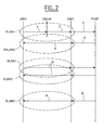
- La figure 2 illustre le fonctionnement de cet exemple, en montrant les échanges de messages de signalisation et de paquets de voix.
- FIG. 1 represents an exemplary embodiment of the local computer network according to the invention.
- Figure 2 illustrates the operation of this example, showing the exchanges of signaling messages and voice packets.
Comme représenté sur la figure 1, cet exemple de réalisation comporte principalement un réseau local informatique LAN qui est préférentiellement de type Ethernet au niveau liaison et de type TCP/IP aux niveaux transport/réseau. Un commutateur téléphonique IPBX est relié à ce réseau local LAN pour commuter des connexions téléphoniques. Divers types de terminal téléphonique sont reliés à ce réseau local LAN, directement ou indirectement :
- Des terminaux téléphoniques fixes, IPP1, IPP2, de type de type Voix sur Protocole Internet (VOIP ou Voice over IP en anglais) qui émettent des signaux de voix sous la forme de paquets Internet, et sont reliés directement au réseau local LAN.
- Des terminaux téléphoniques mobiles, de type Wifi par exemple, MT1, MT2 sont reliés au réseau local LAN, via des point d'accès radio Wifi classiques AP1, AP2.
- Des terminaux téléphoniques fixes analogiques, tel que le terminal POT1, sont reliés au réseau local LAN, via une passerelle GW1 classique, permettant de numériser, comprimer, et mettre sous forme de paquets Internet, des signaux de voix analogiques, et vice versa.
- Des terminaux téléphoniques fixes numériques synchrones, tel que le terminal ST1, sont reliés à un commutateur numérique synchrone PABX1 qui est lui-même relié au réseau local LAN, via une passerelle GW2 classique permettant de numériser, comprimer, et mettre sous forme de paquets Internet, des signaux de voix numériques synchrones, et vice versa.
- Fixed telephone terminals, IPP1, IPP2, of the Voice over Internet Protocol (VOIP) type, which transmit voice signals in the form of Internet packets, and are directly connected to the LAN.
- Mobile telephone terminals, of the Wifi type for example, MT1, MT2 are connected to the local area network LAN, via conventional WiFi radio access points AP1, AP2.
- Analog fixed telephone terminals, such as the POT1 terminal, are connected to the LAN, via a conventional GW1 gateway, for digitizing, compressing, and packaging Internet packets, analog voice signals, and vice versa.
- Synchronous digital fixed telephone terminals, such as the terminal ST1, are connected to a synchronous digital switch PABX1 which is itself connected to the local area network LAN via a conventional GW2 gateway for digitizing, compressing, and packaging Internet packets. , synchronous digital voice signals, and vice versa.
Ce réseau local LAN est relié à un centre d'appels d'urgence PSAP, via une passerelle GW3, et un réseau de téléphonie public PSTN, de type numérique synchrone dans cet exemple. Dans d'autres exemples, le réseau Internet peut être utilisé pour relier ce réseau local au centre d'appels d'urgence.This local area network LAN is connected to a PSAP emergency call center, via a gateway GW3, and a PSTN public telephone network, synchronous digital type in this example. In other examples, the Internet can be used to connect this local network to the emergency call center.
Le centre d'appels d'urgence PSAP est un centre d'appels, classique, qui comporte : un commutateur téléphonique IPBX2 de type Voix sur Protocole Internet ; des terminaux téléphoniques de type Voix sur Protocole Internet tels que le terminal IPP3 ; et des ordinateurs tels que PC1. Des dispositifs d'alarmes AD (Sirène et lampes clignotantes) sont reliés au réseau local LAN pour alerter le personnel de l'entreprise.The PSAP emergency call center is a classic call center that includes: an IP PBX2 Voice Switch over Internet Protocol; voice telephony terminals on Internet Protocol such as the IPP3 terminal; and computers such as PC1. AD alarms (siren and flashing lights) are connected to the LAN to alert the company's staff.
L'autocommutateur IPBX1 comporte des moyens logiciels de contrôle d'admission appels, CAC, pour traiter les demandes d'établissement appels. Ces moyens CAC comportent un sous-ensemble EMSR qui est un serveur appels d'urgence. Ce serveur peut avoir aussi la fonction de localisation, laquelle est indépendante du procédé selon l'invention. Dans cet exemple, les moyens logiciels CAC et EMSR, sont intégrés à l'autocommutateur IPBX1 mais ils pourraient aussi être localisées dans des équipements différents, et dans ce cas là ils dialogueraient entre eux à travers le réseau local LAN. Ce réseau local LAN supporte plusieurs réseaux virtuels et en particulier un ou plusieurs réseaux virtuels dédiés aux appels téléphoniques non urgents.The IPBX1 switch comprises call admission control software means, CAC, for processing call setup requests. These CAC means comprise a subset EMSR which is a server emergency calls. This server can also have the location function, which is independent of the method according to the invention. In this example, the software means CAC and EMSR, are integrated into the switch IPBX1 but they could also be located in different equipment, and in this case they would talk to each other through the LAN LAN. This local area network LAN supports several virtual networks and in particular one or more virtual networks dedicated to non-urgent telephone calls.
Pour exploiter des réseaux virtuels, un pont ou un routeur doit pouvoir distinguer, chaque fois qu'il reçoit un paquet, à quel réseau virtuel appartient ce paquet, et à que quel réseau virtuel appartient la machine destinataire du paquet, cette machine destinataire étant connue par son adresse physique placée dans le paquet.To exploit virtual networks, a bridge or a router must be able to distinguish, each time it receives a packet, to which virtual network this packet belongs, and to which virtual network belongs the recipient machine of the packet, this destination machine being known by his physical address placed in the package.
Lorsqu'une nouvelle machine est connectée à ce réseau local LAN comportant plusieurs réseaux virtuels, il est nécessaire d'attribuer à cette machine une adresse Internet et un identifiant de réseau virtuel. Un protocole connu, appelé protocole de configuration dynamique d'un hôte, ou DHCP (« Dynamic Host Configuration Protocole »), permet d'initialiser et configurer dynamiquement une machine nouvellement connectée à ce réseau. Ce protocole est mis en oeuvre en exécutant un logiciel serveur DHCPS sur l'une des machines du réseau, appelée serveur, et en exécutant des logiciels clients appelés clients DHCP respectivement dans les autres machines du réseau. Par exemple le serveur DHCPS est intégré à l'autocommutateur IPBX1.When a new machine is connected to this local area network LAN having several virtual networks, it is necessary to assign to this machine an Internet address and a virtual network identifier. A known protocol, called Dynamic Host Configuration Protocol (DHCP), is used to dynamically initialize and configure a machine newly connected to this network. This protocol is implemented by running a DHCPS server software on one of the network machines, called a server, and running client software called DHCP clients respectively in the other machines in the network. For example, the DHCPS server is integrated into the IPBX1 switch.
Lorsqu'une machine est mise en fonctionnement dans ce réseau LAN, son client DHCP diffuse dans tout ou partie du réseau un paquet contenant une requête dite DHCP, qui signale au serveur DHCPS la présence de cette nouvelle machine. Le serveur DHCPS choisit une adresse Internet parmi les adresses non attribuées, dans un lot d'adresses prédéterminé. Le serveur DHCPS fournit cette adresse à cette machine pour une durée prédéterminée. Après ce délais, cette adresse est considérée comme libre par le serveur. Il la réutilise pour une autre machine si la machine considérée n'a pas envoyé de message au serveur DHCPS, entre temps, pour demander de nouveau l'attribution d'une adresse Internet.When a machine is put into operation in this LAN, its DHCP client distributes in all or part of the network a packet containing a so-called DHCP request, which signals the server DHCPS the presence of this new machine. The DHCPS server chooses an Internet address from the unassigned addresses, in a predetermined set of addresses. The DHCPS server provides this address to this machine for a predetermined time. After this delay, this address is considered free by the server. It reuses it for another machine if the machine in question has not sent a message to the DHCPS server, in the meantime, to ask again for the attribution of an Internet address.
Conformément au document IETF RFC 2131, le protocole DHCP fournit à chaque machine :
- une référence de transaction,
- une adresse Internet,
- une information de durée d'attribution de cette adresse Internet,
- l'adresse Internet du prochain serveur à utiliser pour l'amorçage de la machine,
- et un champ de paramètres optionnels.
- a transaction reference,
- an Internet address,
- a duration information of attribution of this Internet address,
- the Internet address of the next server to use for booting the machine,
- and an optional parameter field.
On connaît divers procédés pour attribuer un identifiant de réseau virtuel. Un premier procédé automatique connu consiste à utiliser le protocole LLDP (Logical Link Discovery Protocol, IEEE 802.1ab). Un autre procédé automatique s'appuie sur un serveur DHCPS et est décrit dans le document EP1418733. Il consiste à :
- diffuser dans tout le réseau, à partir du terminal, un message contenant :
- -- des informations sur ce terminal ;
- -- une requête destinée au serveur DHCPS et demandant notamment l'attribution d' un identifiant de réseau virtuel, pour ce terminal ;
- et déduire, dans le serveur DHCPS, un identifiant de réseau virtuel notamment à partir des informations sur ce terminal, et envoyer cet identifiant de réseau virtuel au terminal.
- broadcast throughout the network, from the terminal, a message containing:
- - information on this terminal;
- a request to the DHCPS server and in particular requesting the allocation of a virtual network identifier for this terminal;
- and deducing, in the DHCPS server, a virtual network identifier, in particular from the information on this terminal, and sending this virtual network identifier to the terminal.
Ce dernier procédé simplifie la procédure d'installation d'une nouvelle machine puisque c'est le serveur DHCPS qui détermine automatiquement et fournit à la nouvelle machine un identifiant de réseau virtuel. Cet identifiant est déduit des informations sur le terminal, qui sont contenues dans le message diffusé par le terminal. Par exemple si c'est un terminal du type téléphone sur protocole Internet, un identifiant de réseau virtuel voix lui est attribué.The latter method simplifies the installation procedure of a new machine since it is the DHCPS server that automatically determines and provides the new machine with a virtual network identifier. This identifier is derived from the information on the terminal, which is contained in the message broadcast by the terminal. For example, if it is a terminal of the telephone type over Internet protocol, a virtual voice network identifier is assigned to it.
Selon un mode de mise en oeuvre particulier, le message comprend en outre une requête destinée au noeud de rattachement du terminal, et demandant à ce noeud de fournir des indications sur le port, de ce noeud, qui est connecté à ce terminal, en rajoutant ces indications à ce message . Dans le serveur DHCPS de configuration dynamique d'un hôte, un identifiant de réseau virtuel est déduit de ces indications sur le port, et de ces informations sur ce terminal.According to a particular mode of implementation, the message further comprises a request to the terminal node of the terminal, and requesting this node to provide indications on the port, this node, which is connected to this terminal, adding these indications to this message. In the dynamic configuration DHCPS server of a host, a virtual network identifier is deduced from these indications on the port, and this information on this terminal.
Dans le réseau LAN considéré à titre d'exemple, le serveur DHCPS, intégré à l'autocommutateur IPBX1, attribue une identité de réseau virtuel de voix à chaque terminal téléphonique IPP1, IPP2, pour les communications téléphoniques non urgentes, ce serveur détectant automatiquement qu'il s'agit d'un terminal téléphonique grâce à une indication que le terminal met dans son premier message, au démarrage.In the LAN considered by way of example, the DHCPS server, integrated in the IPBX1 switch, allocates a voice virtual network identity to each IPP1 telephone terminal, IPP2, for non-urgent telephone calls, this server automatically detecting that it is a telephone terminal thanks to an indication that the terminal puts in its first message, at startup.
Lorsqu'un utilisateur compose un numéro d'urgence sur le terminal IPP1, des moyens logiciels exécutés dans ce terminal IPP1 reconnaissent ce numéro d'urgence et fournissent à ce terminal deux identités de réseau virtuel :
- Une première identité de réseau virtuel, VLAN1, qu'il utilisera pour l'émission des messages de signalisation et des paquets de voix, à destination d'un centre d'appels d'urgence, ce réseau virtuel VLAN1 ayant une priorité supérieure à celle des réseaux virtuels de voix pour les appels non urgents.
- Une seconde identité de réseau virtuel, VLAN2, qu'il utilisera pour recevoir des messages de signalisation et des paquets de voix, en provenance d'un centre d'appels d'urgence, PSAP, ce réseau virtuel VLAN2 ayant une priorité supérieure à celle des réseaux virtuels de voix pour les appels non urgents. Il rejettera les messages qui ne contiendront pas cette identité de réseau virtuel VLAN2.
- A first virtual network identity, VLAN1, that it will use for sending signaling messages and voice packets, to an emergency call center, this virtual network VLAN1 having a higher priority than the one virtual voice networks for non-emergency calls.
- A second virtual network identity, VLAN2, which it will use to receive signaling messages and voice packets, from an emergency call center, PSAP, this virtual network VLAN2 having a priority higher than that virtual voice networks for non-emergency calls. It will reject messages that do not contain this VLAN2 virtual network identity.
La figure 2 illustre le fonctionnement de cet exemple de réseau local LAN, en montrant les échanges de messages de signalisation et de paquets de voix, dans le cas où le terminal IPP1 demande l'établissement d'un appel d'urgence :
- Etape 1 : Le terminal IPPI détecte qu'un numéro d'urgence a été composé par l'utilisateur de ce terminal. Il émet un message de signalisation comportant :
- -- l'adresse du niveau Contrôle d'Accès au Médium (MAC, ou Medium Access Control en anglais) du terminal ,
- -- l'identifiant du réseau virtuel VLAN1, qui lui assure une priorité maximale pour être transféré ,
- -- et une adresse MAC de mode diffusion, qui indique que le message est destiné à tous les équipements raccordés au réseau virtuel VLAN1 (Le terminal IPP1 n'a donc pas besoin de connaître l'adresse Ethernet du serveur appels d'urgence EMSR, ni celles des dispositifs d'alarme AD).
- Etape 2 : Comme tous les équipements appartenant au réseau virtuel VLAN1, et notamment les dispositifs d'alarme AD, le serveur d'appels d'urgence EMSR reçoit le message de signalisation. L'identité du réseau virtuel VLAN1, qu'il contient, indique que c'est un appel d'urgence. Le serveur d'appels d'urgence EMSR détermine alors, en fonction de la localisation du terminal IPP1, l'identité d'un centre d'appels d'urgence PSAP qui doit être appelé. Le serveur EMSR envoie ensuite un nouveau message de signalisation à la passerelle GW3 qui permet d'accéder au centre d'appels d'urgence PSAP. Ce message contient :
- -- l'identité VLAN1, qui lui assure une priorité maximale pour être transféré,
- -- l'adresse MAC du terminal IPP1,
- -- et une demande d'établissement d'appels entre le terminal IPP1 et le centre d'appels d'urgence PSAP.
- Etape 3 : La passerelle GW3 établit une session entre le terminal IPPI et le centre d'appels PSAP.
- Etape 4 : Le centre d'appels PSAP envoie un accusé de réception à destination de la passerelle GW3.
- Etape 5 : La passerelle GW3 envoie un accusé de réception à destination du terminal IPP1 via le réseau virtuel VLAN2, en utilisant pour le joindre : son adresse MAC et l'identité de réseau virtuel VLAN2. Cet accusé de réception bénéficie de la priorité la plus haute puisqu'il est transféré via le réseau virtuel VLAN2. Cet accusé de réception arrive au terminal IPP1, et à lui seul parce qu'il porte son adresse MAC , ce qui permet une transmission en mode point à point.
- Etape 6 : Une communication téléphonique est établie entre le terminal IPP1 et le centre d'appels PSAP : le terminal IPP1 initialise le transfert de la voix dans un canal utilisant le Protocole de Transport en Temps Réel RTP (Real Time Protocol). Des paquets transportant la voix sont émis en mode diffusion par le terminal IPP1 dans le réseau virtuel VLAN1. La passerelle GW3 utilise l'adresse MAC du terminal IPP1 contenue dans les paquets émis en mode diffusion transportant la voix pour affecter ces paquets à la communication d'urgence correspondante en cas d'appels d'urgence multiples. Des paquets transportant la voix, en provenance du centre d'appels PSAP, sont émis en mode point à point par la passerelle GW3 dans le réseau virtuel VLAN2. La passerelle GW3 assure le transcodage des paquets de voix du canal RTP vers le format adapté au réseau public (par exemple des canaux synchrones, à 64 Kbps, si c'est un réseau numérique à intégration de services), et vice versa.
- Etape 8 : A la fin de l'appel d'urgence, c'est le centre d'appels d'urgence PSAP qui termine l'appel, en envoyant un message de signalisation à la passerelle GW3. Ce message provoque la libération des ressources utilisées dans la passerelle GW3 pour cet appel.
- Etape 9 : La passerelle GW3 transmet un message de relâchement au terminal IPP1, en utilisant son adresse MAC et l'identité de réseau virtuel VLAN2. Ce message a pour effet d'annuler l'attribution du terminal IPP1 aux réseaux virtuels VLAN1 et VLAN2. Il reste attribué à un réseau virtuel de voix pour appels non urgents, et peut donc émettre ou recevoir des appels ordinaires.
- Step 1: The IPPI terminal detects that an emergency number has been dialed by the user of this terminal. It sends a signaling message comprising:
- the address of the Medium Access Control (MAC) level of the terminal,
- the identifier of the virtual network VLAN1, which gives it a maximum priority to be transferred,
- - and a broadcast mode MAC address, which indicates that the message is intended for all the equipment connected to the virtual network VLAN1 (The terminal IPP1 therefore does not need to know the Ethernet address the EMSR emergency call server or the AD alarm devices).
- Step 2: Like all the equipment belonging to the virtual network VLAN1, and in particular the alarm devices AD, the emergency call server EMSR receives the signaling message. The identity of the virtual network VLAN1, which it contains, indicates that it is an emergency call. The EMSR emergency call server then determines, depending on the location of the terminal IPP1, the identity of a PSAP emergency call center to be called. The EMSR server then sends a new signaling message to the GW3 gateway which provides access to the PSAP emergency call center. This message contains:
- - the VLAN1 identity, which gives it a maximum priority to be transferred,
- the MAC address of the terminal IPP1,
- and a call setup request between the IPP1 terminal and the PSAP emergency call center.
- Step 3: The GW3 gateway establishes a session between the IPPI terminal and the PSAP call center.
- Step 4: The PSAP call center sends an acknowledgment to the GW3 gateway.
- Step 5: The gateway GW3 sends an acknowledgment to the terminal IPP1 via the virtual network VLAN2, using to join: its MAC address and the virtual network identity VLAN2. This acknowledgment has the highest priority since it is transferred via the VLAN2 virtual network. This acknowledgment arrives at the terminal IPP1, and alone because it carries its MAC address, which allows transmission in point-to-point mode.
- Step 6: A telephone call is established between the IPP1 terminal and the PSAP call center: the IPP1 terminal initializes the transfer of the voice in a channel using Real Time Protocol Real Time Transport Protocol (RTP). Packets carrying the voice are transmitted in broadcast mode by the terminal IPP1 in the virtual network VLAN1. The gateway GW3 uses the MAC address of the terminal IPP1 contained in the packets transmitted in broadcast mode carrying the voice to assign these packets to the emergency communication corresponding to multiple emergency calls. Packets carrying the voice, from the PSAP call center, are transmitted in point-to-point mode by the GW3 gateway in the VLAN2 virtual network. The GW3 gateway transcodes voice packets from the RTP channel to the public network format (for example synchronous channels, at 64 Kbps, if it is an integrated services digital network), and vice versa.
- Step 8: At the end of the emergency call, the PSAP emergency call center terminates the call, sending a signaling message to the GW3 gateway. This message causes the resources used in the GW3 gateway to be released for this call.
- Step 9: The gateway GW3 transmits a release message to the IPP1 terminal, using its MAC address and the VLAN2 virtual network identity. This message has the effect of canceling the assignment of the terminal IPP1 to the virtual networks VLAN1 and VLAN2. It remains assigned to a virtual voice network for non-emergency calls, and can therefore send or receive ordinary calls.
Selon une variante de mise en oeuvre, le serveur d'appels d'urgence EMSR établit, en plus de la connexion avec le PSAP, une connexion entre le terminal IPP1 désigné par l'adresse MAC d'origine, que contient le message de notification, et un autre terminal prédéterminé du réseau d'entreprise, par exemple POT1. Ce terminal, dit tiers, est par exemple un terminal téléphonique situé dans un poste de gardiennage de l'entreprise.According to an implementation variant, the emergency call server EMSR establishes, in addition to the connection with the PSAP, a connection between the terminal IPP1 designated by the original MAC address, which contains the notification message , and another predetermined terminal of the corporate network, for example POT1. This terminal, said third party, is for example a telephone terminal located in a guarding position of the company.
A cause de la diversité des types de terminal téléphonique qui peuvent être présents dans un réseau téléphonique, il est prévu que les passerelles GW1 et GW2 remplissent les fonctions que les terminaux analogiques, tels que POT1, et les terminaux synchrones, tels que ST1, ne peuvent pas remplir, pour établir des appels dans le réseau local LAN. Par exemple, la passerelle GW1 comporte des moyens logiciels pour :
- reconnaître qu'un message de signalisation émis par le terminal POT1 est un message de demande l'établissement d'un appel d'urgence, et retransmettre ce message en mode diffusion dans le réseau local LAN en ajoutant à ce message une étiquette constituée de l'identificateur de réseau virtuel
VLAN 1 ; - étiqueter tous les paquets de données provenant de ce terminal POT1, avec l'identité du premier réseau virtuel VLAN1, pendant la durée d'un appel d'urgence ;
- et retransmettre à ce terminal POT1 tout message portant une adresse MAC correspondant à ce terminal POT1, et portant l'identificateur de réseau virtuel VLAN2 ; et ne laissant pas passer ceux qui ne portent pas l'identité du second réseau virtuel VLAN2, pendant la durée de l'appel d'urgence.
- recognize that a signaling message sent by the terminal POT1 is a message requesting the establishment of an emergency call, and retransmit this broadcast message in the local area network LAN by adding to this message a label consisting of VLAN
virtual network identifier 1; - tag all data packets from this terminal POT1, with the identity of the first virtual network VLAN1, during the duration of an emergency call;
- and retransmitting to this terminal POT1 any message carrying a MAC address corresponding to this terminal POT1, and carrying the virtual network identifier VLAN2; and not letting those who do not carry the identity of the second virtual network VLAN2 for the duration of the emergency call.
D'autres types de terminaux, des terminaux de données ou multimédia ne comportant pas de fonction de transmission de la voix peuvent être utilisés par des utilisateurs handicapés pour appeler un centre d'appels d'urgence, par exemple une personne sourde et muette. Ces terminaux comprennent une application adaptée à la communication de données, et, tout comme le terminal vocal IPP1, ces terminaux de données comprennent des moyens leur permettant de déterminer si l'utilisateur appelle ou non un centre d'appels d'urgence, et pour attribuer ces terminaux aux premier et second réseaux virtuels VLAN1 et VLAN2 pour transporter des données autres que des paquets de voix.Other types of terminals, data terminals or multimedia not having a voice transmission function can be used by disabled users to call an emergency call center, for example a deaf and dumb person. These terminals include an application suitable for data communication, and, like the voice terminal IPP1, these data terminals include means for determining whether or not the user calls an emergency call center, and for assigning these terminals to the first and second virtual networks VLAN1 and VLAN2 to carry data other than voice packets.
Claims (7)
Priority Applications (8)
| Application Number | Priority Date | Filing Date | Title |
|---|---|---|---|
| ES05290188T ES2333602T3 (en) | 2005-01-26 | 2005-01-26 | PROCEDURE TO ESTABLISH AN EMERGENCY CALL IN A LOCAL, TERMINAL, PASSWAY AND SERVER INFORMATIC NETWORK FOR THE PRACTICE OF THIS PROCEDURE. |
| EP05290188A EP1686552B1 (en) | 2005-01-26 | 2005-01-26 | Method for establishing an emergency call in a local area network, terminal, gateways and server for such a method |
| AT05290188T ATE443308T1 (en) | 2005-01-26 | 2005-01-26 | METHOD FOR MAKING AN EMERGENCY CALL IN A LOCAL INFORMATION NETWORK, TERMINAL DEVICE, NETWORK TRANSITIONS AND SERVER DEVICE FOR SUCH A METHOD |
| DE602005016647T DE602005016647D1 (en) | 2005-01-26 | 2005-01-26 | Method for issuing an emergency call in a local information network, terminal, gateways and server facility for such a method |
| US11/814,768 US8428049B2 (en) | 2005-01-26 | 2006-01-25 | Method for setting up an emergency call in a computer local area network, terminal and server for implementing the method |
| CNB2006800029959A CN100511307C (en) | 2005-01-26 | 2006-01-25 | Method for establishing an emergency call in a local information network, terminal and server for such a method |
| PCT/FR2006/050053 WO2006079745A1 (en) | 2005-01-26 | 2006-01-25 | Method for setting up an emergency call in a local computer network, terminal and server therefor |
| JP2007552692A JP4794578B2 (en) | 2005-01-26 | 2006-01-25 | Method for establishing emergency call in computer local area network, and terminal device and server therefor |
Applications Claiming Priority (1)
| Application Number | Priority Date | Filing Date | Title |
|---|---|---|---|
| EP05290188A EP1686552B1 (en) | 2005-01-26 | 2005-01-26 | Method for establishing an emergency call in a local area network, terminal, gateways and server for such a method |
Publications (2)
| Publication Number | Publication Date |
|---|---|
| EP1686552A1 true EP1686552A1 (en) | 2006-08-02 |
| EP1686552B1 EP1686552B1 (en) | 2009-09-16 |
Family
ID=34941909
Family Applications (1)
| Application Number | Title | Priority Date | Filing Date |
|---|---|---|---|
| EP05290188A Active EP1686552B1 (en) | 2005-01-26 | 2005-01-26 | Method for establishing an emergency call in a local area network, terminal, gateways and server for such a method |
Country Status (8)
| Country | Link |
|---|---|
| US (1) | US8428049B2 (en) |
| EP (1) | EP1686552B1 (en) |
| JP (1) | JP4794578B2 (en) |
| CN (1) | CN100511307C (en) |
| AT (1) | ATE443308T1 (en) |
| DE (1) | DE602005016647D1 (en) |
| ES (1) | ES2333602T3 (en) |
| WO (1) | WO2006079745A1 (en) |
Cited By (2)
| Publication number | Priority date | Publication date | Assignee | Title |
|---|---|---|---|---|
| CN102572139A (en) * | 2011-12-15 | 2012-07-11 | 中兴通讯股份有限公司 | Information processing method, business processing method and device |
| US8737395B2 (en) | 2012-01-23 | 2014-05-27 | Adva Optical Networking Se | Method for accessing a network and network access device |
Families Citing this family (18)
| Publication number | Priority date | Publication date | Assignee | Title |
|---|---|---|---|---|
| US8397168B2 (en) | 2008-04-05 | 2013-03-12 | Social Communications Company | Interfacing with a spatial virtual communication environment |
| US7769806B2 (en) | 2007-10-24 | 2010-08-03 | Social Communications Company | Automated real-time data stream switching in a shared virtual area communication environment |
| US9148769B2 (en) | 2008-05-07 | 2015-09-29 | Qualcomm Incorporated | System, apparatus and method to enable mobile stations to identify calls based on predetermined values set in a call header |
| NO330630B1 (en) * | 2009-07-01 | 2011-05-30 | Tandberg Telecom As | System and procedure for making a call using a global register |
| CN101930656B (en) * | 2010-07-30 | 2012-12-12 | 武汉烽火众智数字技术有限责任公司 | Method for processing alarm message of safe city video monitoring system |
| WO2013078062A1 (en) * | 2011-11-23 | 2013-05-30 | Social Communications Company | Creating and managing virtual areas |
| EP2618526A1 (en) * | 2012-01-23 | 2013-07-24 | ADVA Optical Networking SE | Method and network access device for accessing a virtual private network |
| US10110417B1 (en) | 2012-07-06 | 2018-10-23 | Cradlepoint, Inc. | Private networks overlaid on cloud infrastructure |
| US10880162B1 (en) | 2012-07-06 | 2020-12-29 | Cradlepoint, Inc. | Linking logical broadcast domains |
| US10177957B1 (en) | 2012-07-06 | 2019-01-08 | Cradlepoint, Inc. | Connecting a cloud network to the internet |
| US10601653B2 (en) | 2012-07-06 | 2020-03-24 | Cradlepoint, Inc. | Implicit traffic engineering |
| US9992062B1 (en) | 2012-07-06 | 2018-06-05 | Cradlepoint, Inc. | Implicit traffic engineering |
| US10135677B1 (en) | 2012-07-06 | 2018-11-20 | Cradlepoint, Inc. | Deployment of network-related features over cloud network |
| US10560343B1 (en) | 2012-07-06 | 2020-02-11 | Cradlepoint, Inc. | People centric management of cloud networks via GUI |
| US9712489B2 (en) * | 2014-07-29 | 2017-07-18 | Aruba Networks, Inc. | Client device address assignment following authentication |
| US9380144B1 (en) * | 2015-01-30 | 2016-06-28 | Lenovo Enterprise Solutions (Singapore) Pte. Ltd. | Mobile wireless communication device emergency mode |
| JP6325499B2 (en) * | 2015-09-17 | 2018-05-16 | 双葉電子工業株式会社 | Wireless device, network system, and control method |
| PL3503599T3 (en) | 2017-12-22 | 2020-07-27 | Deutsche Telekom Ag | Emergency network slice and method and access network entity for processing an emergency communication in a packet switched communication network |
Citations (3)
| Publication number | Priority date | Publication date | Assignee | Title |
|---|---|---|---|---|
| US20020085538A1 (en) * | 2000-12-29 | 2002-07-04 | Leung Mun Keung | Emergency calling with a VoIP device in a VLAN environment |
| EP1435707A1 (en) * | 2002-12-31 | 2004-07-07 | Alcatel | Automated voice over IP device VLAN-association Setup |
| JP2004364017A (en) * | 2003-06-05 | 2004-12-24 | Ricoh Co Ltd | Connection system, adapter and apparatus for ip telephone and connection method |
Family Cites Families (41)
| Publication number | Priority date | Publication date | Assignee | Title |
|---|---|---|---|---|
| JP3164994B2 (en) * | 1995-02-27 | 2001-05-14 | 株式会社日立製作所 | ATM network and node device and failure notification control method |
| GB2337386B (en) * | 1996-09-09 | 2001-04-04 | Dennis J Dupray | Location of a mobile station |
| US7714778B2 (en) * | 1997-08-20 | 2010-05-11 | Tracbeam Llc | Wireless location gateway and applications therefor |
| US6236365B1 (en) * | 1996-09-09 | 2001-05-22 | Tracbeam, Llc | Location of a mobile station using a plurality of commercial wireless infrastructures |
| DE19643186C2 (en) * | 1996-10-18 | 1998-12-03 | Siemens Ag | Method for accessing mobile communication terminals to public, private or home communication areas |
| US5999541A (en) * | 1997-02-28 | 1999-12-07 | 3Com Corporation | Transmission of token-ring packets over ethernet by tunneling |
| US6038438A (en) * | 1997-12-30 | 2000-03-14 | Ericsson, Inc. | Emergency radio beacon capable mobile communication system mobile telephone and method |
| US6118866A (en) * | 1998-08-03 | 2000-09-12 | Geneys Telecommunications Laboratories, Inc. | Emergency call load management for call centers |
| US7428002B2 (en) * | 2002-06-05 | 2008-09-23 | Monroe David A | Emergency telephone with integrated surveillance system connectivity |
| US7366157B1 (en) * | 1998-11-17 | 2008-04-29 | Ericsson Inc. | Methods and system for routing emergency calls through the internet |
| GB2361389B (en) * | 2000-04-15 | 2004-01-28 | Ericsson Telefon Ab L M | Telecommunications system |
| US20020001307A1 (en) * | 2000-05-20 | 2002-01-03 | Equipe Communications Corporation | VPI/VCI availability index |
| GB0016351D0 (en) * | 2000-07-03 | 2000-08-23 | Nokia Networks Oy | Interaction in a communication system |
| DE10101282A1 (en) * | 2001-01-12 | 2002-07-18 | Siemens Ag | Emergency call notification using mobile telecommunication devices |
| US7096269B2 (en) * | 2001-03-30 | 2006-08-22 | Hitachi, Ltd. | Path selection methods for storage based remote copy |
| DE60142450D1 (en) * | 2001-04-27 | 2010-08-05 | Nokia Corp | SUBSCRIBER DEVICE, NETWORK ELEMENT, AND METHOD AND COMMUNICATION SYSTEM FOR MAKING AN EMERGENCY SESSION |
| JP2003069592A (en) * | 2001-08-23 | 2003-03-07 | Fujikura Ltd | Switching hub control circuit and switching hub |
| US7630359B1 (en) * | 2001-09-28 | 2009-12-08 | At&T Corp. | Technique for providing translation between the packet environment and the PSTN environment |
| JP2003198757A (en) * | 2001-12-26 | 2003-07-11 | Nec Commun Syst Ltd | Internet telephone terminal and emergency call connecting system for internet telephone system |
| US7050809B2 (en) * | 2001-12-27 | 2006-05-23 | Samsung Electronics Co., Ltd. | System and method for providing concurrent data transmissions in a wireless communication network |
| US6741173B2 (en) * | 2002-01-25 | 2004-05-25 | International Business Machines Corporation | Distributed alarm system |
| US7206306B2 (en) * | 2002-03-26 | 2007-04-17 | Siemens Communications, Inc. | System and method for emergency call diversion |
| JP3794484B2 (en) * | 2002-06-24 | 2006-07-05 | 松下電器産業株式会社 | Internet telephone system and call connection method thereof |
| NL1021127C2 (en) * | 2002-07-22 | 2004-01-23 | Gsm Innovations B V | Method and device for medium selection in mobile telephony. |
| EP1416745A1 (en) * | 2002-10-31 | 2004-05-06 | Siemens Aktiengesellschaft | Localisation method |
| US7388868B2 (en) * | 2002-12-17 | 2008-06-17 | Alcatel Lucent | Call-routing apparatus, and associated method, for providing local call handling functions in a communication network |
| JP2004260696A (en) * | 2003-02-27 | 2004-09-16 | Nippon Telegr & Teleph Corp <Ntt> | Frame transfer network |
| GB0306711D0 (en) * | 2003-03-24 | 2003-04-30 | Nokia Corp | Positioning in a communications system |
| JP3709881B2 (en) * | 2003-06-04 | 2005-10-26 | オムロン株式会社 | Machine security system, control device, remote alarm, control method, control program, and computer-readable recording medium recording the control program |
| US7483374B2 (en) * | 2003-08-05 | 2009-01-27 | Scalent Systems, Inc. | Method and apparatus for achieving dynamic capacity and high availability in multi-stage data networks using adaptive flow-based routing |
| US7042985B1 (en) * | 2003-08-27 | 2006-05-09 | Bellsouth Intellectual Property Corporation | Method, system and computer program product for providing a regional E911 network |
| US7675890B2 (en) * | 2003-09-10 | 2010-03-09 | Delta Networks, Inc. | QoS based load-balance policy for WLAN |
| US20050169248A1 (en) * | 2004-02-04 | 2005-08-04 | Nortel Networks Limited | Method and apparatus for providing in-band location information in an emergency response network |
| US7386111B2 (en) * | 2004-02-10 | 2008-06-10 | Vonage Network Inc. | Method and apparatus for placing a long distance call based on a virtual phone number |
| US7508754B1 (en) * | 2004-02-27 | 2009-03-24 | Sprint Spectrum L.P. | Method and system to support internal calling upon loss of connection with IP Centrex server |
| US7177399B2 (en) * | 2004-02-27 | 2007-02-13 | Nortel Network Limited | Determining the geographical location from which an emergency call originates in a packet-based communications network |
| US7133499B2 (en) * | 2004-04-27 | 2006-11-07 | Qwest Communications International, Inc. | Systems and methods for processing emergency calls through a public switched telephone network |
| ES2246702B2 (en) * | 2004-06-02 | 2007-06-16 | L & M DATA COMMUNICATIONS, S.A. | ETHERNET UNIVERSAL TELECOMMUNICATIONS SERVICE. |
| US7894406B2 (en) * | 2004-09-30 | 2011-02-22 | Alcatel-Lucent Usa Inc. | System for routing remote VoIP emergency calls |
| US7079627B2 (en) * | 2004-10-13 | 2006-07-18 | Bce Inc. | Emergency call handling in a voice-over-packet environment |
| US7734019B1 (en) * | 2004-12-09 | 2010-06-08 | Level 3 Communications, Llc | Systems and methods for third party emergency call termination |
-
2005
- 2005-01-26 EP EP05290188A patent/EP1686552B1/en active Active
- 2005-01-26 ES ES05290188T patent/ES2333602T3/en active Active
- 2005-01-26 AT AT05290188T patent/ATE443308T1/en not_active IP Right Cessation
- 2005-01-26 DE DE602005016647T patent/DE602005016647D1/en active Active
-
2006
- 2006-01-25 WO PCT/FR2006/050053 patent/WO2006079745A1/en not_active Application Discontinuation
- 2006-01-25 JP JP2007552692A patent/JP4794578B2/en not_active Expired - Fee Related
- 2006-01-25 US US11/814,768 patent/US8428049B2/en not_active Expired - Fee Related
- 2006-01-25 CN CNB2006800029959A patent/CN100511307C/en active Active
Patent Citations (3)
| Publication number | Priority date | Publication date | Assignee | Title |
|---|---|---|---|---|
| US20020085538A1 (en) * | 2000-12-29 | 2002-07-04 | Leung Mun Keung | Emergency calling with a VoIP device in a VLAN environment |
| EP1435707A1 (en) * | 2002-12-31 | 2004-07-07 | Alcatel | Automated voice over IP device VLAN-association Setup |
| JP2004364017A (en) * | 2003-06-05 | 2004-12-24 | Ricoh Co Ltd | Connection system, adapter and apparatus for ip telephone and connection method |
Non-Patent Citations (1)
| Title |
|---|
| PATENT ABSTRACTS OF JAPAN vol. 2003, no. 12 5 December 2003 (2003-12-05) * |
Cited By (2)
| Publication number | Priority date | Publication date | Assignee | Title |
|---|---|---|---|---|
| CN102572139A (en) * | 2011-12-15 | 2012-07-11 | 中兴通讯股份有限公司 | Information processing method, business processing method and device |
| US8737395B2 (en) | 2012-01-23 | 2014-05-27 | Adva Optical Networking Se | Method for accessing a network and network access device |
Also Published As
| Publication number | Publication date |
|---|---|
| EP1686552B1 (en) | 2009-09-16 |
| CN101107639A (en) | 2008-01-16 |
| WO2006079745A1 (en) | 2006-08-03 |
| US8428049B2 (en) | 2013-04-23 |
| CN100511307C (en) | 2009-07-08 |
| JP2008529377A (en) | 2008-07-31 |
| JP4794578B2 (en) | 2011-10-19 |
| ATE443308T1 (en) | 2009-10-15 |
| DE602005016647D1 (en) | 2009-10-29 |
| ES2333602T3 (en) | 2010-02-24 |
| US20090316683A1 (en) | 2009-12-24 |
Similar Documents
| Publication | Publication Date | Title |
|---|---|---|
| EP1686552B1 (en) | Method for establishing an emergency call in a local area network, terminal, gateways and server for such a method | |
| US7281043B1 (en) | System for sharing resources among RSVP sessions | |
| KR100454502B1 (en) | Apparatus for providing QoS on IP router and method for forwarding VoIP traffic | |
| EP1585264B1 (en) | Method for indicating classification of a communications flow | |
| US8121028B1 (en) | Quality of service provisioning for packet service sessions in communication networks | |
| WO2006108168A2 (en) | Interworking qsig and h.323 signaling in a sip-based network | |
| CN103634490A (en) | A gateway for the survivability of an enterprise network using SIP | |
| US20050195949A1 (en) | Status transmission system and method | |
| US20060018255A1 (en) | Defining a static path through a communications network to provide wiretap law compliance | |
| US7068594B1 (en) | Method and apparatus for fault tolerant permanent voice calls in voice-over-packet systems | |
| EP1552650B1 (en) | Method for the automatic configuration of an ip telephony device and/or data, system and device implementing same | |
| AU5069102A (en) | Selection system, its selection method for voice channels, and switchboard for use therein | |
| EP1111894A1 (en) | Communication system and method for establishing a conversation using different link layer thechnologies | |
| US8804506B2 (en) | Voice/data combination system and method for managing bandwidth in the system | |
| TWI240516B (en) | System for automatically selecting voice data transmission and reception system for IP network, method thereof, and IP terminal | |
| US20030083081A1 (en) | Service management agent for managing the provision of different services to a communication device | |
| EP1432210B1 (en) | System to control processes associated to flows inside a communication network | |
| EP1653699A1 (en) | Routing frames in an IP sonet ring using an IP proxy server | |
| CN109479071A (en) | A kind of processing method and related network device of the networking telephone | |
| JP4189965B2 (en) | Communication node | |
| US6975625B1 (en) | Distributed call control processing | |
| JP4143479B2 (en) | Communication system between subscriber terminals | |
| US7852832B1 (en) | Method and apparatus for providing secure interface to externally hosted application servers | |
| EP2648385B1 (en) | External services for internal calls | |
| US7697513B1 (en) | Private branch exchange (PBX) networking over IP networks |
Legal Events
| Date | Code | Title | Description |
|---|---|---|---|
| PUAI | Public reference made under article 153(3) epc to a published international application that has entered the european phase |
Free format text: ORIGINAL CODE: 0009012 |
|
| AK | Designated contracting states |
Kind code of ref document: A1 Designated state(s): AT BE BG CH CY CZ DE DK EE ES FI FR GB GR HU IE IS IT LI LT LU MC NL PL PT RO SE SI SK TR |
|
| AX | Request for extension of the european patent |
Extension state: AL BA HR LV MK YU |
|
| 17P | Request for examination filed |
Effective date: 20061229 |
|
| RAP1 | Party data changed (applicant data changed or rights of an application transferred) |
Owner name: ALCATEL LUCENT |
|
| AKX | Designation fees paid |
Designated state(s): AT BE BG CH CY CZ DE DK EE ES FI FR GB GR HU IE IS IT LI LT LU MC NL PL PT RO SE SI SK TR |
|
| GRAP | Despatch of communication of intention to grant a patent |
Free format text: ORIGINAL CODE: EPIDOSNIGR1 |
|
| RTI1 | Title (correction) |
Free format text: METHOD FOR ESTABLISHING AN EMERGENCY CALL IN A LOCAL AREA NETWORK, TERMINAL, GATEWAYS AND SERVER FOR SUCH A METHOD |
|
| GRAS | Grant fee paid |
Free format text: ORIGINAL CODE: EPIDOSNIGR3 |
|
| GRAA | (expected) grant |
Free format text: ORIGINAL CODE: 0009210 |
|
| AK | Designated contracting states |
Kind code of ref document: B1 Designated state(s): AT BE BG CH CY CZ DE DK EE ES FI FR GB GR HU IE IS IT LI LT LU MC NL PL PT RO SE SI SK TR |
|
| REG | Reference to a national code |
Ref country code: GB Ref legal event code: FG4D Free format text: NOT ENGLISH |
|
| REG | Reference to a national code |
Ref country code: CH Ref legal event code: EP |
|
| REG | Reference to a national code |
Ref country code: IE Ref legal event code: FG4D |
|
| REF | Corresponds to: |
Ref document number: 602005016647 Country of ref document: DE Date of ref document: 20091029 Kind code of ref document: P |
|
| PG25 | Lapsed in a contracting state [announced via postgrant information from national office to epo] |
Ref country code: SE Free format text: LAPSE BECAUSE OF FAILURE TO SUBMIT A TRANSLATION OF THE DESCRIPTION OR TO PAY THE FEE WITHIN THE PRESCRIBED TIME-LIMIT Effective date: 20090916 Ref country code: FI Free format text: LAPSE BECAUSE OF FAILURE TO SUBMIT A TRANSLATION OF THE DESCRIPTION OR TO PAY THE FEE WITHIN THE PRESCRIBED TIME-LIMIT Effective date: 20090916 Ref country code: LT Free format text: LAPSE BECAUSE OF FAILURE TO SUBMIT A TRANSLATION OF THE DESCRIPTION OR TO PAY THE FEE WITHIN THE PRESCRIBED TIME-LIMIT Effective date: 20090916 |
|
| REG | Reference to a national code |
Ref country code: ES Ref legal event code: FG2A Ref document number: 2333602 Country of ref document: ES Kind code of ref document: T3 |
|
| LTIE | Lt: invalidation of european patent or patent extension |
Effective date: 20090916 |
|
| PG25 | Lapsed in a contracting state [announced via postgrant information from national office to epo] |
Ref country code: SI Free format text: LAPSE BECAUSE OF FAILURE TO SUBMIT A TRANSLATION OF THE DESCRIPTION OR TO PAY THE FEE WITHIN THE PRESCRIBED TIME-LIMIT Effective date: 20090916 Ref country code: PL Free format text: LAPSE BECAUSE OF FAILURE TO SUBMIT A TRANSLATION OF THE DESCRIPTION OR TO PAY THE FEE WITHIN THE PRESCRIBED TIME-LIMIT Effective date: 20090916 Ref country code: NL Free format text: LAPSE BECAUSE OF FAILURE TO SUBMIT A TRANSLATION OF THE DESCRIPTION OR TO PAY THE FEE WITHIN THE PRESCRIBED TIME-LIMIT Effective date: 20090916 |
|
| NLV1 | Nl: lapsed or annulled due to failure to fulfill the requirements of art. 29p and 29m of the patents act | ||
| PG25 | Lapsed in a contracting state [announced via postgrant information from national office to epo] |
Ref country code: CY Free format text: LAPSE BECAUSE OF FAILURE TO SUBMIT A TRANSLATION OF THE DESCRIPTION OR TO PAY THE FEE WITHIN THE PRESCRIBED TIME-LIMIT Effective date: 20090916 |
|
| REG | Reference to a national code |
Ref country code: IE Ref legal event code: FD4D |
|
| PG25 | Lapsed in a contracting state [announced via postgrant information from national office to epo] |
Ref country code: EE Free format text: LAPSE BECAUSE OF FAILURE TO SUBMIT A TRANSLATION OF THE DESCRIPTION OR TO PAY THE FEE WITHIN THE PRESCRIBED TIME-LIMIT Effective date: 20090916 Ref country code: IS Free format text: LAPSE BECAUSE OF FAILURE TO SUBMIT A TRANSLATION OF THE DESCRIPTION OR TO PAY THE FEE WITHIN THE PRESCRIBED TIME-LIMIT Effective date: 20100116 Ref country code: CZ Free format text: LAPSE BECAUSE OF FAILURE TO SUBMIT A TRANSLATION OF THE DESCRIPTION OR TO PAY THE FEE WITHIN THE PRESCRIBED TIME-LIMIT Effective date: 20090916 Ref country code: PT Free format text: LAPSE BECAUSE OF FAILURE TO SUBMIT A TRANSLATION OF THE DESCRIPTION OR TO PAY THE FEE WITHIN THE PRESCRIBED TIME-LIMIT Effective date: 20100118 Ref country code: IE Free format text: LAPSE BECAUSE OF FAILURE TO SUBMIT A TRANSLATION OF THE DESCRIPTION OR TO PAY THE FEE WITHIN THE PRESCRIBED TIME-LIMIT Effective date: 20090916 Ref country code: RO Free format text: LAPSE BECAUSE OF FAILURE TO SUBMIT A TRANSLATION OF THE DESCRIPTION OR TO PAY THE FEE WITHIN THE PRESCRIBED TIME-LIMIT Effective date: 20090916 |
|
| PG25 | Lapsed in a contracting state [announced via postgrant information from national office to epo] |
Ref country code: SK Free format text: LAPSE BECAUSE OF FAILURE TO SUBMIT A TRANSLATION OF THE DESCRIPTION OR TO PAY THE FEE WITHIN THE PRESCRIBED TIME-LIMIT Effective date: 20090916 |
|
| PG25 | Lapsed in a contracting state [announced via postgrant information from national office to epo] |
Ref country code: AT Free format text: LAPSE BECAUSE OF FAILURE TO SUBMIT A TRANSLATION OF THE DESCRIPTION OR TO PAY THE FEE WITHIN THE PRESCRIBED TIME-LIMIT Effective date: 20090916 |
|
| PLBE | No opposition filed within time limit |
Free format text: ORIGINAL CODE: 0009261 |
|
| STAA | Information on the status of an ep patent application or granted ep patent |
Free format text: STATUS: NO OPPOSITION FILED WITHIN TIME LIMIT |
|
| PG25 | Lapsed in a contracting state [announced via postgrant information from national office to epo] |
Ref country code: DK Free format text: LAPSE BECAUSE OF FAILURE TO SUBMIT A TRANSLATION OF THE DESCRIPTION OR TO PAY THE FEE WITHIN THE PRESCRIBED TIME-LIMIT Effective date: 20090916 |
|
| BERE | Be: lapsed |
Owner name: ALCATEL LUCENT Effective date: 20100131 |
|
| 26N | No opposition filed |
Effective date: 20100617 |
|
| PG25 | Lapsed in a contracting state [announced via postgrant information from national office to epo] |
Ref country code: MC Free format text: LAPSE BECAUSE OF NON-PAYMENT OF DUE FEES Effective date: 20100131 |
|
| REG | Reference to a national code |
Ref country code: CH Ref legal event code: PL |
|
| PG25 | Lapsed in a contracting state [announced via postgrant information from national office to epo] |
Ref country code: LI Free format text: LAPSE BECAUSE OF NON-PAYMENT OF DUE FEES Effective date: 20100131 Ref country code: CH Free format text: LAPSE BECAUSE OF NON-PAYMENT OF DUE FEES Effective date: 20100131 Ref country code: GR Free format text: LAPSE BECAUSE OF FAILURE TO SUBMIT A TRANSLATION OF THE DESCRIPTION OR TO PAY THE FEE WITHIN THE PRESCRIBED TIME-LIMIT Effective date: 20091217 |
|
| PG25 | Lapsed in a contracting state [announced via postgrant information from national office to epo] |
Ref country code: BE Free format text: LAPSE BECAUSE OF NON-PAYMENT OF DUE FEES Effective date: 20100131 |
|
| PG25 | Lapsed in a contracting state [announced via postgrant information from national office to epo] |
Ref country code: LU Free format text: LAPSE BECAUSE OF NON-PAYMENT OF DUE FEES Effective date: 20100126 Ref country code: BG Free format text: LAPSE BECAUSE OF FAILURE TO SUBMIT A TRANSLATION OF THE DESCRIPTION OR TO PAY THE FEE WITHIN THE PRESCRIBED TIME-LIMIT Effective date: 20090916 Ref country code: HU Free format text: LAPSE BECAUSE OF FAILURE TO SUBMIT A TRANSLATION OF THE DESCRIPTION OR TO PAY THE FEE WITHIN THE PRESCRIBED TIME-LIMIT Effective date: 20100317 |
|
| PG25 | Lapsed in a contracting state [announced via postgrant information from national office to epo] |
Ref country code: TR Free format text: LAPSE BECAUSE OF FAILURE TO SUBMIT A TRANSLATION OF THE DESCRIPTION OR TO PAY THE FEE WITHIN THE PRESCRIBED TIME-LIMIT Effective date: 20090916 |
|
| REG | Reference to a national code |
Ref country code: GB Ref legal event code: 732E Free format text: REGISTERED BETWEEN 20130926 AND 20131002 |
|
| REG | Reference to a national code |
Ref country code: FR Ref legal event code: GC Effective date: 20131018 |
|
| REG | Reference to a national code |
Ref country code: FR Ref legal event code: RG Effective date: 20141016 |
|
| REG | Reference to a national code |
Ref country code: FR Ref legal event code: PLFP Year of fee payment: 11 |
|
| REG | Reference to a national code |
Ref country code: FR Ref legal event code: CA Effective date: 20150521 |
|
| REG | Reference to a national code |
Ref country code: FR Ref legal event code: CA Effective date: 20150521 |
|
| REG | Reference to a national code |
Ref country code: FR Ref legal event code: PLFP Year of fee payment: 12 |
|
| REG | Reference to a national code |
Ref country code: FR Ref legal event code: PLFP Year of fee payment: 13 |
|
| REG | Reference to a national code |
Ref country code: FR Ref legal event code: PLFP Year of fee payment: 14 |
|
| PGFP | Annual fee paid to national office [announced via postgrant information from national office to epo] |
Ref country code: IT Payment date: 20180122 Year of fee payment: 14 |
|
| PG25 | Lapsed in a contracting state [announced via postgrant information from national office to epo] |
Ref country code: IT Free format text: LAPSE BECAUSE OF NON-PAYMENT OF DUE FEES Effective date: 20190126 |
|
| REG | Reference to a national code |
Ref country code: DE Ref legal event code: R082 Ref document number: 602005016647 Country of ref document: DE Representative=s name: METACOM LEGAL RECHTSANWAELTE, DE Ref country code: DE Ref legal event code: R082 Ref document number: 602005016647 Country of ref document: DE Representative=s name: METACOM LEGAL, DE Ref country code: DE Ref legal event code: R081 Ref document number: 602005016647 Country of ref document: DE Owner name: WSOU INVESTMENTS, LLC, LOS ANGELES, US Free format text: FORMER OWNER: ALCATEL LUCENT, PARIS, FR Ref country code: DE Ref legal event code: R082 Ref document number: 602005016647 Country of ref document: DE Representative=s name: BARKHOFF REIMANN VOSSIUS, DE |
|
| REG | Reference to a national code |
Ref country code: GB Ref legal event code: 732E Free format text: REGISTERED BETWEEN 20200827 AND 20200902 |
|
| REG | Reference to a national code |
Ref country code: ES Ref legal event code: PC2A Owner name: WSOU INVESTMENTS, LLC Effective date: 20201001 |
|
| REG | Reference to a national code |
Ref country code: DE Ref legal event code: R082 Ref document number: 602005016647 Country of ref document: DE Representative=s name: METACOM LEGAL RECHTSANWAELTE, DE Ref country code: DE Ref legal event code: R082 Ref document number: 602005016647 Country of ref document: DE Representative=s name: METACOM LEGAL, DE |
|
| P01 | Opt-out of the competence of the unified patent court (upc) registered |
Effective date: 20230606 |
|
| PGFP | Annual fee paid to national office [announced via postgrant information from national office to epo] |
Ref country code: FR Payment date: 20230626 Year of fee payment: 19 Ref country code: DE Payment date: 20230626 Year of fee payment: 19 |
|
| PGFP | Annual fee paid to national office [announced via postgrant information from national office to epo] |
Ref country code: GB Payment date: 20230627 Year of fee payment: 19 Ref country code: ES Payment date: 20230703 Year of fee payment: 19 |