EP1680515B1 - Chemical analysis using dynamic viscometry - Google Patents
Chemical analysis using dynamic viscometry Download PDFInfo
- Publication number
- EP1680515B1 EP1680515B1 EP04797232A EP04797232A EP1680515B1 EP 1680515 B1 EP1680515 B1 EP 1680515B1 EP 04797232 A EP04797232 A EP 04797232A EP 04797232 A EP04797232 A EP 04797232A EP 1680515 B1 EP1680515 B1 EP 1680515B1
- Authority
- EP
- European Patent Office
- Prior art keywords
- reaction
- viscometer
- resonator
- contact surface
- transducer
- Prior art date
- Legal status (The legal status is an assumption and is not a legal conclusion. Google has not performed a legal analysis and makes no representation as to the accuracy of the status listed.)
- Not-in-force
Links
Images

Classifications
-
- G—PHYSICS
- G01—MEASURING; TESTING
- G01N—INVESTIGATING OR ANALYSING MATERIALS BY DETERMINING THEIR CHEMICAL OR PHYSICAL PROPERTIES
- G01N11/00—Investigating flow properties of materials, e.g. viscosity, plasticity; Analysing materials by determining flow properties
- G01N11/10—Investigating flow properties of materials, e.g. viscosity, plasticity; Analysing materials by determining flow properties by moving a body within the material
- G01N11/16—Investigating flow properties of materials, e.g. viscosity, plasticity; Analysing materials by determining flow properties by moving a body within the material by measuring damping effect upon oscillatory body
- G01N11/162—Oscillations being torsional, e.g. produced by rotating bodies
-
- C—CHEMISTRY; METALLURGY
- C12—BIOCHEMISTRY; BEER; SPIRITS; WINE; VINEGAR; MICROBIOLOGY; ENZYMOLOGY; MUTATION OR GENETIC ENGINEERING
- C12Q—MEASURING OR TESTING PROCESSES INVOLVING ENZYMES, NUCLEIC ACIDS OR MICROORGANISMS; COMPOSITIONS OR TEST PAPERS THEREFOR; PROCESSES OF PREPARING SUCH COMPOSITIONS; CONDITION-RESPONSIVE CONTROL IN MICROBIOLOGICAL OR ENZYMOLOGICAL PROCESSES
- C12Q1/00—Measuring or testing processes involving enzymes, nucleic acids or microorganisms; Compositions therefor; Processes of preparing such compositions
- C12Q1/68—Measuring or testing processes involving enzymes, nucleic acids or microorganisms; Compositions therefor; Processes of preparing such compositions involving nucleic acids
- C12Q1/6813—Hybridisation assays
- C12Q1/6816—Hybridisation assays characterised by the detection means
-
- Y—GENERAL TAGGING OF NEW TECHNOLOGICAL DEVELOPMENTS; GENERAL TAGGING OF CROSS-SECTIONAL TECHNOLOGIES SPANNING OVER SEVERAL SECTIONS OF THE IPC; TECHNICAL SUBJECTS COVERED BY FORMER USPC CROSS-REFERENCE ART COLLECTIONS [XRACs] AND DIGESTS
- Y10—TECHNICAL SUBJECTS COVERED BY FORMER USPC
- Y10T—TECHNICAL SUBJECTS COVERED BY FORMER US CLASSIFICATION
- Y10T436/00—Chemistry: analytical and immunological testing
- Y10T436/14—Heterocyclic carbon compound [i.e., O, S, N, Se, Te, as only ring hetero atom]
- Y10T436/145555—Hetero-N
Definitions
- the present invention relates to a method and a device for determining the reaction state of a chemical reaction, in particular a reaction for the amplification of nucleic acids.
- reaction result In chemical reactions, it is usually desirable to quantify the reaction result by measuring suitable quantities or to follow the course of the reaction on the basis of such a size.
- a known example is the tracking of color changes of a color indicator added to a reaction mixture.
- an educt In an amplification process of nucleic acids, in contrast to the usual chemical reaction, an educt is not converted into a completely different product, but rather a part of a molecule is multiplied with the aid of other educts.
- the reaction result today is frequently quantified by staining with ethidium bromide and detection of the fluorescence signal. It has also been proposed to detect the hybridization process itself by fluorescence. Such a method is in the US 6,174,670 disclosed.
- the detected fluorescence signal results from fluorescence resonance energy transfer (FRET) between two fluorophores upon excitation of the fluorescence resonance energy transfer (FRET) Donor fluorophores with light.
- FRET fluorescence resonance energy transfer
- Fluorescence monitoring of the reaction process is relatively expensive because a sensitive optical system must be provided for detection. In addition, such a method is expensive because of the necessary fluorescent markers in use.
- the process should be easy to carry out and inexpensive. This object is achieved by a method with the Features of claim 1.
- the inventive method comprises a viscosity determination of the reaction mixture. This can be done with a suitable viscometer, preferably with a dynamic viscometer. However, it is also possible to use a different viscometer, e.g. a capillary viscometer, as known in the art.
- the reaction state, in particular the result, of a chemical reaction is determined.
- the chemical reaction comprises at least one reaction step in which an amplification of nucleic acids takes place.
- the method is characterized in that a measurement of the viscosity is made.
- the method according to the invention makes it possible to determine very inexpensively whether and to what extent an amplification has actually taken place. This is based on the finding that virtually any amplification reaction leads to a change in viscosity, such as a polymerase chain reaction (PCR), a ligase chain reaction (LCR) or a NASBA Reaction (Nucleic Acid Sequence Based Amplification).
- PCR polymerase chain reaction
- LCR ligase chain reaction
- NASBA Reaction Nucleic Acid Sequence Based Amplification
- the method according to the invention makes it possible to carry out screening methods for the presence of nucleic acids of specific organisms very cost-effectively or for the presence of a mutation in the genome of an organism, in particular a microbial, plant or animal (including human) organism.
- the method preferably comprises further evaluation steps, which make it possible to determine the presence of a mutation in a nucleic acid.
- the amplification reaction comprises an allele-specific amplification reaction, as known in the art.
- Allele-specific amplification is an amplification in which the amount of nucleic acid fragments generated by the reaction depends on the absence or presence of the mutation on the initial target sequence.
- the further evaluation steps then preferably comprise a step in which the determined measure of the viscosity is compared with a previously measured or calculated comparison measure, the result of this comparison permitting a decision on the existence of the mutation.
- the reaction process preferably comprises at least one reaction step in which nucleic acid fragments are linked together, preferably in a form in which the fragments polymerize with one another.
- the linkage of target nucleic acid fragments by means of linker oligonucleotides takes place.
- the linker oligonucleotide is configured to hybridize to a first probe region near its 5 'end on a first nucleic acid fragment and to hybridize to a second probe region near its 3' end on a second nucleic acid fragment.
- the linker oligonucleotides themselves are subsequently linked to such a hybridization process by means of a ligase. This can be done in the form of an LCR.
- the linker oligonucleotide preferably comprises a linker region which comprises a repetitive arrangement of bases, eg a range of preferably 5 to 20 identical bases, eg T bases.
- the linker oligonucleotide is preferably selected such that a base which preferably has the 3'-end of the linker Oligonucleotide or few, preferably one or two, positions away from the 3 'end is complementary to the base of the target sequence at the mutation site.
- the linker region and the adjoining regions are designed such that essentially no hybridization of the two probe regions to a single nucleic acid fragment with the target sequence takes place, but that preferably each of the probe regions hybridizes to a respective nucleic acid fragment which has the target sequence.
- the 5 'end of the linker oligonucleotide is preferably phosphorylated.
- linker oligonucleotides takes place here, on the other hand additionally a linkage of the linker oligonucleotides.
- the linkage can result in a linear macromolecule and / or a network.
- linear macromolecule and “network”, reference is made to the IUPAC Compendium of Chemical Terminology, 2nd Edition (1997).
- the viscosity determination is preferably carried out with a dynamic viscometer, but can also be done, for example, with a known capillary viscometer.
- a dynamic viscometer is to be understood as an apparatus which comprises a resonator which is capable of a mechanical self-oscillation, preferably a torsional oscillation.
- the resonator in this case has a contact surface which can be brought into contact with a fluid.
- a transducer e.g. a piezoelectric transducer or an electromagnetic transducer
- the resonator and thus the contact surface can be excited to vibrate.
- the fluid at the contact surface will dampen the vibration.
- a measure of the viscosity of the fluid can then be derived from the damping of the resonator.
- a quantitative determination of the viscosity becomes possible when the density of the fluid is known.
- a dynamic viscometer is easy to use, inexpensive to manufacture, and highly sensitive to small viscosity changes. While dynamic viscometers are known per se, the method according to the invention is distinguished by the fact that the dynamic viscometer is used to obtain information on the state of the reaction from the viscosity. In contrast to methods which are typically used for monitoring large-scale polymerization reactions, the method according to the invention is particularly suitable for applications in which the amount of the reaction mixture is relatively small.
- a great advantage of using a dynamic viscometer in the process according to the invention lies in the high sensitivity which can be achieved with dynamic viscometers. Even small viscosity changes, on the scale of a few percent or less, in small sample volumes can be detected with such a viscometer.
- the reaction mixture is in a sample chamber containing the contact surface of the resonator and whose volume is less than 1 milliliter, preferably less than 100 microliters, in an advantageous embodiment less than 10 microliters.
- the volume of the sample space will exceed 1 microliter; however, if the viscometer is designed accordingly, the volume can fall below this value.
- the present invention also specifies particular embodiments of the viscometer.
- the sample space is at least partially limited by capillary forces. Especially with small sample volumes, it is very easy to bring a precisely predetermined region of the contact surface into contact with the reaction mixture and to keep it there during the measurement.
- a reaction process can take place while the reaction mixture is in the sample space of the viscometer, or the reaction mixture is introduced into the viscometer only after the reaction has ended.
- Advantages arise when at least part of the reaction process takes place while the reaction mixture is in contact with the contact surface, since then aufinroiree sample transfers can be omitted.
- the reaction process is an amplification reaction for nucleic acids, since such a possible contamination is avoided and a complex manual handling step can be dispensed with.
- the contact surface is formed by the inside of a glass tube, and on the glass tube is advantageously a tempering element, e.g. a heating element or both heating and cooling permitting Peltier element, vapor-deposited.
- the text below also describes an apparatus for determining the reaction state of a viscosity-altering chemical reaction process in a reaction mixture. This is characterized by the fact that they are comprises dynamic viscometer with a torsional oscillator as a resonator.
- the device comprises a resonator having a contact surface and capable of torsional vibration parallel to the contact surface, and at least one first transducer cooperating with the resonator.
- the viscometer preferably comprises a temperature control element arranged close to the contact surface.
- This may be a pure heating element, e.g. a heating wire, but is preferably an element that allows both heating and cooling, e.g. a Peltier element.
- the tempering element is preferably attached to the resonator. It can be produced by vapor deposition of metal layers on the resonator, in particular if it comprises a glass tube.
- the tempering element can simultaneously serve to exert a force or a torque on the resonator through the Lorentz force acting in an external magnetic field.
- the tempering may be part of the (electromagnetic) transducer.
- an oscillation of the resonator in an external magnetic field then leads to induced stresses in the tempering element, which can serve to detect the oscillation.
- the viscometer preferably comprises means for generating a static magnetic field, in particular one or more permanent magnets, in the vicinity of the tempering element.
- the resonator comprises a (mineral) glass tube with an outer diameter of 1 millimeter or less.
- the outer diameter is 0.5 millimeters or less.
- the inner diameter is preferably 0.8 mm or less, more preferably 0.4 mm or less.
- the wall thickness is preferably between 0.02 millimeter and 0.1 millimeter, more preferably about 0.05 millimeter.
- the glass tube preferably consists of quartz glass.
- a resonator with such a glass tube has a high sensitivity, among other things due to the special mechanical properties of glasses, in particular quartz glass, and due to the low specific mass compared to many metallic materials.
- glass is highly chemically inert, which prevents the resonator material from being attacked or chemically altered by the reaction mixture.
- a glass tube is particularly well suited for vapor deposition of metal areas, whereby a temperature control element can be produced in a particularly cost-effective manner. This is particularly interesting when the resonator is designed as a disposable product.
- the glass tube is preferably attached to a first and a second inertial mass whose mass is in each case a multiple (at least ten times) of the mass of the glass tube.
- Each inertial mass is connected directly or indirectly, for example via a weakened area, which acts as a spring element, with a housing or holder.
- the transducer is arranged in the region between the inertial masses near a vibration antinode (antinode, region of maximum amplitude) of a natural oscillation of the resonator.
- the transducer is located in the middle between the inertial masses.
- the interior of the tube forms the contact surface for the reaction mixture.
- the glass tube is preferably releasably attached to the inertial masses, e.g. by means of a clamping bush.
- current-carrying elements are present on the glass tube, which are part of the transducer and are used for magnetic field generation.
- the resonator has a tube and a contact body. This is connected to the tube and has a Diameter larger than the diameter of the tube, preferably at least twice the diameter of the glass tube. An outer surface of the contact body forms the contact surface.
- the contact body is characterized in that it is designed for direct electromagnetic interaction with a magnetic field generated by the transducer, ie it is part of the (electromagnetic) transducer.
- the contact body comprises a permanent magnet or is formed by such a permanent magnet.
- the viscometer then includes at least one pair of electromagnets arranged to magnetically interact with the permanent magnet.
- the contact body may also comprise at least one electromagnet.
- the device comprises a metering device for the reaction mixture, which may be attached to a holder or housing or is formed by the housing itself.
- the metering device is arranged near the contact body and has an opening in the region of the contact surface. Through this opening, the reaction mixture is introduced into a predetermined area between the contact surface and the metering device.
- the metering device is spaced from the contact surface such that the reaction mixture is held in this predetermined range by capillary forces. As a result, the reaction mixture remains limited in a defined sample volume.
- the resonator preferably comprises a tube with a contact body of larger diameter attached thereto.
- the opening is preferably central, i. substantially concentric with the tube.
- the viscometer is operated with a phase-locked loop, as shown in the US 4,920,787 or the WO 95/24630 is described in detail.
- the device has a feedback device which comprises an oscillator which drives the first transducer.
- the feedback device is intended to to stabilize the resonator in the range of a natural frequency.
- an output of the feedback device is connected at least indirectly to the first transducer, which excites the resonator to oscillate.
- the same transducer also serves to detect the vibrations, or there is a second transducer for this purpose on the resonator.
- An input of the feedback device is at least indirectly connected to the first transducer or the second transducer. Operation with such a control loop enables particularly stable, reproducible measurements.
- WO 95/24630 discloses a first switch between the output of the feedback device and the first converter and a second switch between the first and second converter and the input of the feedback device.
- the switches may comprise any suitable electronic means, eg transistors. The measurement can then be done in a clocked mode, without affecting the high frequency stability of the phase control loop.
- This mode of operation has proven to be particularly low in interference, making it particularly suitable for small amounts of sample.
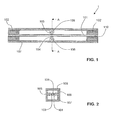
- the Fig. 1 shows a highly schematic representation of a first embodiment of a device 1.
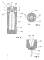
- the Fig. 2 shows the device of Fig. 1 also seen very schematically in cross section in the direction AA. Identical parts are provided with the same reference numerals.
- a quartz glass tube 101 which forms the resonator, is fastened in the region of its two ends in each case in an inertial mass 102, 102 '.
- the inertial masses are connected to a housing 107, for example by gluing. Both ends of the glass tube are accessible from the outside to introduce a liquid reaction mixture 110 into the glass tube.
- the glass tube protrudes, for example in a manner not shown at both ends by a certain range from the inertial masses, and there are provided suitable connections for supplying the reaction mixture. This is for example in the Fig. 12 of the WO 95/24630 shown. In operation, the interior of the glass tube thus serves as a contact surface.
- the converter serves alternately both as an actuator for excitation and as a sensor for detection. Of course, but also separate converter to these Be provided for purposes.
- the diameter of the glass tube 101 is shown greatly enlarged.
- the preferred outer diameter of the glass tube is less than 1 millimeter, in a concrete example realized only 0.5 millimeters.
- the wall thickness of the glass tube is preferably less than 0.1 millimeters, in the example mentioned only 0.05 millimeters.
- the inner diameter in the example mentioned is 0.4 millimeters.
- the length of the glass tube is preferably between about 30 millimeters and 100 millimeters, in the example mentioned about 80 millimeters.
- the sample space volume present in the interior of the glass tube is approximately 10 mm 3 , ie 10 microliters. With such a viscometer so very small amounts of reaction mixture can be examined.
- the material of the glass tube is preferably a quartz glass.
- This material is preferable since it has very little self-damping and low density, which enables a high Q-factor and a high sensitivity. Thanks to the low G-modulus of the material, it is possible to prevent the boundary layer from becoming too small.
- the resonant frequency of the fundamental is in the range between about 1 kHz and about 100 kHz; in the mentioned concrete example it was approximately 14.7 kHz.
- the glass tube was a commercially available quartz glass tube, e.g. from VitroCom Inc. of Mount Lakes, New Jersey (USA).
- the reaction mixture in contact with the contact surface increases the damping of the resonator.
- the viscosity is determined from the measured attenuation of the resonator. This can be done analytically from the relationship of viscosity and damping or by a calibration.
- the device is preferably operated, as in the WO 95/24630 is described.
- the electromagnets 105, 106 of the Electromagnetic transducer connected to a circuit, as in the Fig. 1 to 8 as well as on page 4, line 1 to page 9, line 31 of the WO 95/24630 is shown.
- the circuit is an example of a feedback circuit to stabilize the resonator near its natural frequency. The attenuation of the resonator is determined by measuring the frequency shift as the phase changes between the excitation signal in the transducer and the detected signal in the transducer.
- the device of Fig. 1 and 2 is preferably designed so that all coming into contact with the reaction mixture parts, in particular the glass tube 101, can be easily replaced.
- the glass tube 101 is held in the inertial masses 102, 102 'preferably with fastening means not shown in detail, which allow easy release of the connection between the glass tube and inertial mass.
- fastening means not shown in detail, which allow easy release of the connection between the glass tube and inertial mass.
- Suitable are, for example, clamping bush made of plastic or metal, as are well known in the art and cause, for example by screwing a secure connection between the glass tube and inertial. It is important that the connection is sufficiently strong, so that the held in the fasteners glass area is actually not capable of torsional vibrations.
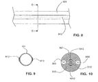
- the Fig. 3 shows a schematic representation of a second configuration of a device, denoted by the numeral 3.
- the Fig. 4 shows the device of Fig. 3 in cross-section in the direction BB.
- the resonator again comprises a quartz glass tube 301, which is fastened with one end in an inertial mass 302. At the other end a cylindrical contact body 303 is placed.
- the inertial mass 302 is fixed in a housing 307. This is formed in the vicinity of the contact body so cylindrical that it surrounds the contact body along its peripheral surface at a constant distance.
- Opposite the end face of the contact body there is an opening 311 in the housing, through which a reaction mixture 310 can be introduced into the area bounded by the contact body 303 and the housing 307.
- the housing expands inside strong on. Likewise, the opening 311 widens away from the contact body 303. These expansions and the distances between contact body 303 and housing 307 are selected so that the reaction mixture is held by capillary forces in the intended area. By a suitable choice of the size of the contact body and the distances also the amount of the reaction mixture can be greatly reduced.
- the contact body 303 is formed as a permanent magnet whose magnetic field is substantially perpendicular to the long axis of the tube 301.
- the magnet may be provided with a chemical inert coating. This permanent magnet is suitable for magnetic interactions with two electromagnets 305, 306. Contact body 303 and electromagnets 305, 306 thus together form an electromagnetic transducer, and the contact body is itself part of this converter.
- the contact body is e.g. formed by an Sm-Co permanent magnet which has been hydrophilized on its surface by known methods to ensure good wetting.
- the tube 301 By excitation of the transducer with electrical signals matching frequency, the tube 301 is excited to torsional vibrations, preferably in the fundamental mode. The vibrations are detected by the same transducer as a sensor.
- the viscometer of Fig. 3 is essentially like that of the Fig. 1 operated; the comments made above apply accordingly analogously.
- the resonant frequency of the resonator is again preferably in the range between 1 and 100 kHz.
- the contact body has a diameter of 2.0 millimeters and a length of 0.7 millimeters.
- the inner diameter of the housing surrounding the contact body is 3.0 millimeters, ie, the gap between the contact body 303 and housing 307 has a width of 0.5 millimeters.
- the total sample volume in such a viscometer is about 15 microliters.
- these dimensions depending on the specific application of the viscometer, vary within a wide range.
- An important aspect in the choice of the dimensions of the contact body is the resonant frequency of the resonator, which is the lower, the greater the mass of the contact body 303.
- the viscometer of Fig. 3 Due to its simple structure, it is also particularly suitable as a disposable viscometer whose parts in contact with the reaction mixture can simply be thrown away after use.
- the electromagnets 305, 306 of the transducer are easily detachably attached to the housing 307. Housing 307, inertial mass 302, tube 301 and contact body 303 form a disposable unit which, after use, is discarded and replaced with a new unit.
- the housing can be inexpensively manufactured from a plastic, eg polypropylene, in particular in a (precision) injection molding process. The same applies to the inertial mass.
- the electromagnets can also be held in a separate housing, for example a retaining ring, the viscometer housing 307 being designed to be insertable into it, for example.
- the Fig. 5 shows a schematic representation of a third embodiment of the device, denoted by the numeral 5.
- This device is in the Fig. 6 shown in cross-section in the viewing direction CC.
- the resonator comprises a glass tube 501 which is connected at one end to an inertial mass 502.
- the inertial mass is inserted in a housing 507.
- a contact body 503 is attached at the other end of the glass tube 501.
- this is designed as a permanent magnet and interacts magnetically with electromagnets 505, 506. So he is part of an electromagnetic transducer.
- a metering element 508 is screwed into the housing 507.
- This has a funnel-shaped metering region 509 for receiving a reaction mixture 510, which opens downwardly into an opening 511. Through this opening, the reaction mixture reaches the contact surface, which is formed by the end face of the contact body 503. Capillary forces hold the reaction mixture on this surface.
- the sample space is thus limited to the area between the end face of the contact body 503 and the metering element 508.
- the distance between the contact body and dosing element can e.g. by means of a fine thread, not shown, on the cylindrical peripheral surface of the metering element 508, which cooperates with a corresponding internal thread of the housing 507, can be varied.
- the reaction mixture can be confined to a thin layer whose thickness can be adjusted in the order of magnitude of the boundary layer formed when the resonator performs torsional vibrations.
- the Fig. 7 shows a section of a similar viscometer, which according to the principles of Fig. 5 is constructed. Only a part of the glass tube 501, the contact body 503 'and the metering element 508' with metering region 509 'and opening 511', together with the reaction mixture 510, are shown. While the end face of the contact body 503 'is flat, the metering element 508' has a conical shape in the area opposite the end face. As a result, the distance between the contact body 503 'and the metering element 508' expands radially.
- This configuration on the one hand provides an effective limitation of the reaction mixture by capillary forces to the desired Safe area. On the other hand, this configuration ensures that a substantially spatially uniform shear rate (uniform velocity gradient along the axial direction) is achieved throughout the reaction mixture. With this configuration, very small sample volumes can be achieved, especially in the range of a few microliters.
- the viscometers may be provided with means for controlling the temperature (heating and / or cooling) of the reaction mixture.
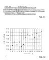
- the Fig. 8 shows as an example schematically and greatly enlarged part of a glass tube 101 from a viscometer according to the Fig. 1 ,
- the Fig. 9 represents the glass tube in cross section in the direction DD.
- two metal strips 812, 813 are deposited, which act as heating wires. This allows the reaction mixture located inside the glass tube 101 to heat up slightly. Instead of a layer extending in the axial direction, this can also run helically around the glass tube, for example.
- a Peltier element can be arranged in the vicinity of the sample space. This makes it possible to optionally heat or cool the reaction mixture.
- a suitable Peltier element may e.g. applied directly to the glass tube (e.g., glued), or it may be formed on the glass tube by vapor deposition of two different metals. Depending on the current direction, a Peltier element can serve both as a heating element and as a cooling element.
- the tempering element is at the same time part of the electromagnetic transducer, ie, a Lorentz force acts on the electrons in the metal of the tempering element in a magnetic field, which is used to excite the resonator and / or to detect the oscillations of the resonator is used.
- a Lorentz force acts on the electrons in the metal of the tempering element in a magnetic field, which is used to excite the resonator and / or to detect the oscillations of the resonator is used.
- the tempering and other metal strips may be vapor-deposited or applied in other ways, for example in the form of coils.
- the tempering element acting as part of the converter and / or the additional metal strips can be operated in a first operating mode with direct current. In operation, they then interact with an alternating magnetic field generated by the electromagnets 105, 106 to excite the resonator.
- the coils 105, 106 can be replaced by permanent magnets, and both the excitation and the vibration detection is carried out completely by means of the tempering or the additional metal strips instead of by means of the coils 105, 106th
- the existing on the glass tube 101 metal areas can be connected in a known manner to electrical leads.
- electrical leads e.g. Contact fields formed near the ends of the glass tube. After insertion of the glass tube into the inertial masses, these contact pads are in contact with contacts for the electrical leads, which are e.g. be provided in the bore of the inertial masses or at another suitable location.
- the glass tube is designed as a disposable glass tube, that is designed to be removed after use and replaced.
- the permanent magnets 103, 104 can be omitted, which leads to a significant cost savings.
- Fig. 10 a variant of the viscometer of Fig. 4 in which two heating elements 1012, 1013 are located on the inner surface of the housing 307 surrounding the contact body 303.
- These can be formed for example from current-carrying pieces of wire or in another known manner be educated.
- tempering elements e.g. allow the generation of temperature gradients.
- suitable temperature sensors e.g., Pt-100 probes, etc.
- the presence of one or more tempering is especially useful when a reaction is to be performed directly in the viscometer, but also has other advantages, since the viscosity is usually highly temperature-dependent and tempering can improve the reproducibility of the measurement.
- the reaction mixture may e.g. are cooled to a temperature near the solidification point of the reaction mixture, e.g. in the range between 0 ° C and 10 ° C with dilute aqueous solutions, which usually causes a significant increase in viscosity, and stabilized there.
- stabilization in the range of e.g. ⁇ 0.1 ° C is required, which can be achieved faster and easier with the mentioned tempering than with a temperature control of the entire viscometer.
- a temperature control is particularly interesting if an amplification reaction of nucleic acid fragments is carried out, in particular a PCR or LCR which requires frequent temperature changes (temperature cycles). Due to the temperature control, the reaction can take place directly in the sample space of the viscometer, and the amplification can be monitored directly at suitable points of the temperature cycles on the basis of the viscosity change. In a method for mutation detection by means of allele-specific amplification, the reaction can be terminated immediately, for example, as soon as a change in viscosity occurs, which indicates the presence of the mutation. Without temperature control of the viscometer, the amplification in a separate reaction apparatus for the amplification process is first carried out for a fixed number of cycles. The sample must then be removed from the reaction device and then transferred to the viscometer. It is obvious that this can be done with a higher and workload is connected.
- Mutations on the genetic material include the lack of single base pairs (single nucleotide polymorphisms SNPs), the absence of a whole sequence unit (deletion) or the presence of excess genetic information (insertion).
- SNPs single nucleotide polymorphisms
- insertion the presence of excess genetic information
- gel electrophoresis with restriction enzymes which uses ethidium bromide as a staining method.
- restriction enzymes which uses ethidium bromide as a staining method.
- fluorophores to visualize the reaction.
- the increase in viscosity in a chemical process such as PCR is in principle theoretically calculable. It converts nucleotides into longer, double-stranded products, so that the molecules are larger and water is released, which has previously surrounded the nucleotides.
- the Viscosity will change as polymers are synthesized. The resulting in the reaction so-called templates often reach a size of 250 to 500mer.
- the molecules formed in the amplification are preferably interconnected (linear linkage and / or crosslinking). This process is then performed following the amplification or coupled to it.
- the linkage is preferably carried out with an LCR incorporating suitable linker molecules.
- the mutation for factor V Leiden is a single point mutation (G instead of A) in the human gene sequence that results in the protein coded by the sequence (a coagulation factor) at position 506 being replaced by an arginine residue. Further information about this mutation can be found eg in RM Bertina et al., "Mutation in Blood Coagulation Factor V Associated with Resistance to Activated Protein C", Nature 369, 64-67 (1994 ). The entire nucleotide sequence of the factor V gene is described in: RJ Jenny et al., “Complete cDNA and Derived Amino Acid Sequence of Human Factor V", Proc. Nat. Acad. USA 84, 4846-4850 (1987 ). In individuals with the mutation, the risk of thrombosis is markedly increased over wild-type individuals, and this mutation is the subject of frequent laboratory testing in clinical genetics laboratories.
- the gene segment is amplified by means of PCR.
- the amplification product is digested with a restriction endonuclease which cuts only the wild-type sequence, but not the mutant. Wild type and mutant can then be differentiated by gel electrophoresis. This process is time consuming and requires a large number of manual steps.
- the "mutation site” is the nucleotide position in the gene of the factor V at which a guanine base in the wild type is replaced by an adenine base in the mutant.
- Fig. 11 illustrates how these oligonucleotides correspond to the sequence of the factor V gene.
- a fragment of the double strand of the factor V gene in the vicinity of the mutation site is shown centrally.
- the oligonucleotides are designed to hybridize at the indicated sites to the single strands.
- probe_for stands for either "wild type_for” or “mutation_for”
- probe_rev stands for either "wild type_rev” or "mutation_rev”.
- the oligonucleotide "Probe_for” is used for the connection with the oligonucleotide "General_for", which is phosphorylated at the 5 'end, analogously the oligonucleotide "Probe_rev” for the connection with the 5'-phosphorylated oligonucleotide "General_rev”.
- the molecules "WT_Linker_for”, “WT_Linker_rev”, “Mut_Linker_for” and “Mut_Linker_for” are formed by connecting these molecules via a linker of (preferably) nine T bases and are designed with their 5 'side sections on a first nucleotide and their 3 'side sections to hybridize to another nucleotide.
- a linker of (preferably) nine T bases are designed with their 5 'side sections on a first nucleotide and their 3 'side sections to hybridize to another nucleotide.
- Tm indicates the melting point calculated by the nearest neighbor method.
- LCR Long PCR a "normal" LCR was performed after the PCR.
- the LCR was performed as follows: "Ampligase 1X Reaction Buffer” from Epicenter Technologies (20 mM Tris-HCl (pH 8.3), 25 mM KCl, 10 mM MgCl 2 , 0.5 mM NAD, and 0.01% Triton X-100). was provided.
- the probes "WT_Linker_for” (SEQ ID NO 9) and “WT_Linker_rev” (SEQ ID NO 10) served as special bridging molecules, which bind between the two ends of each one of the polymerase synthesized PCR products.
- the probe "WT_Linker_for” (SEQ ID NO 9) both the sequence of the probe "General_for” (SEQ ID NO 5) and the sequence "Wild Type_for” (SEQ ID NO 3).
- These are connected by means of a linker region of 9 T bases, wherein the number of bases can also be chosen differently.
- 5 and 20 bases appear to be in the linker region, preferably 5 to 10.
- the 5 'region of the "WT_Linker_for" probe (SEQ ID NO 9) now hybridizes to the corresponding region of a first nucleotide, while the 3' region hybridizes to the corresponding region of a second nucleotide. If on this second nucleotide the 5 'end of another probe molecule is hybridized, the two probe molecules are linked by the ligase. In this way, a longer-chain polymer is formed. The formation of this polymer leads to a marked increase in viscosity.
- the ligase linkage will only occur if the sequence of the probe at the 3 'end corresponds exactly to the sequence of the nucleotide. A single base exchange at the 3 'end will therefore inhibit LCR. In this way, the LCR is also allele specific.
- the adapted LCR was performed as follows: "Ampligase 1X Reaction Buffer” from Epicenter Technologies; 50 microliter of reaction buffer, 50 nmol each of the probes named “WT_Linker_for”, “WT_Linker_rev”, 1.5-5 U Ampligase (Epicenter Technologies). The concentration of ampligase depends on the type of ampligase used. Incubated at 95 ° C for 30 seconds, followed by incubation at 50 ° C for 30 seconds for 45 seconds; 35 cycles.
- Fig. 1 The product was then tested in a dynamic viscometer, as described in Fig. 1 is shown (quartz glass tube as a resonator, length 80 mm, outer diameter 0.5 mm, wall thickness 0.05 mm). The sample was cooled to 10 ° C and the temperature stabilized in a range of ⁇ 0.1 ° C.
- n denotes the consecutive number of the measurement, ⁇ the viscosity.
- further control measurements not shown, were carried out.
- the number of nucleic acids already present is decisive for the design of the method. If a sufficient number of molecules are present, e.g. to dispense with a PCR amplification and equal to the LCR be performed. For example, for the detection of DNA from bacterial suspensions, as an alternative to PCR with coupled LCR, an LCR alone, without PCR, can also be carried out. Similarly, only one PCR or only one LCR can be performed for the detection of DNA from thymus, if the amount of nucleic acid is so large that a change in viscosity can be measured by one of these methods alone.
- the specially adapted LCR as described herein is advantageous, but not essential in all situations. Thus, under certain circumstances, only the increase in viscosity due to a PCR or a conventional LCR can be sufficient for detection. In the case of a sufficiently high number of nucleic acid sequences, a product increase on the basis of an increase in viscosity alone could be detected, in particular alone by means of allele-specific amplification, as one Form of "real-time PCR".
- the PCR process can also be made dependent on the mutation, in that the amplification takes place only if the mutation is present. In such a case, then only the amplified sequences could be ligated in subsequent LCR, so only those of a mutation. On the non-mutated, no PCR can be performed and therefore there is also too little starting material for an LCR, which consequently does not lead to an increase in viscosity.
- Such selective amplification is achieved by means of allele-specific amplification in which a primer is developed for the mutation. Such methods are well known in the art.
- a method is also conceivable in which a PCR cycle and an LCR cycle or a so-called ligation detection reaction (LDR) are alternately run through.
- LDR ligation detection reaction
- OLA oligonucleotide ligation assay
- Another very interesting option is to perform a gap LCR instead of the PCR or subsequently to the PCR.
- a gap LCR complementary probe pairs are inserted with a 3 'extension. After these have hybridized to the target sequence DNA, there is a gap of one or more bases to the adjacent probe.
- a thermostable polymerase for the automation process
- the appropriate nucleotides float in solution
- the usage of Probe duplexes with non-complementary 3 'extensions prevent the formation of target-independent ligase products (so-called "blunt-end” ligation).
- a gap LCR was used instead of the PCR.
- a reaction mixture was prepared as follows.
- the reaction buffer used was "Ampligase 10X Reaction Buffer" from Epicenter Technologies. This contained: 200 mM Tris-HCl (pH 8.3), 250 mM KCl, 100 mM MgCl 2 , 5 mM NAD, and 0.1% Triton X-100.
- To 50 microliters of reaction buffer was added: in each case 50 nmol of suitable probes for the gap LCR, 1.5 U DNA polymerase without 3 ' ⁇ 5' exonuclease activity (from Thermus flavus) (MBR, Milwaukee, WI), 20 mM K + , 1.5-5 U Ampligase (Epicenter Technologies).
- Unit U catalyzes the ligation of 50% of cos sites into 1 microgram lambda DNA for 1 minute at 45 ° C in 1X Ampligase Reaction Buffer.
- 1 U Ampligase DNA ligase is equivalent to at least 15 "Cohesive End Units" or "Nick Ligation Units", which are otherwise commonly used in the art.
- the ampligase was provided in a storage buffer having the following composition: 50% glycerol with 50 mM Tris-HCl (pH 7.5), 0.1 M NaCl, 0.1 mM EDTA, 1 mM DTT, and 0.1% Triton X-100. The reaction volume was overlaid with 50 microliters of mineral oil.
- adapted gap LCR in which the probes are designed such that they hybridize with their ends on different nucleic acid fragments, analogously to the adapted LCR described above.
- the process according to the invention is generally used for determining the reaction state of an amplification reaction.
- the process could also be used for other viscosity-altering chemical reactions, in particular for small sample quantities.
Landscapes
- Chemical & Material Sciences (AREA)
- Life Sciences & Earth Sciences (AREA)
- Organic Chemistry (AREA)
- Health & Medical Sciences (AREA)
- General Health & Medical Sciences (AREA)
- Biochemistry (AREA)
- Analytical Chemistry (AREA)
- Zoology (AREA)
- Immunology (AREA)
- Wood Science & Technology (AREA)
- Physics & Mathematics (AREA)
- Proteomics, Peptides & Aminoacids (AREA)
- Engineering & Computer Science (AREA)
- Biophysics (AREA)
- Microbiology (AREA)
- Molecular Biology (AREA)
- Biotechnology (AREA)
- Pathology (AREA)
- General Physics & Mathematics (AREA)
- Bioinformatics & Cheminformatics (AREA)
- General Engineering & Computer Science (AREA)
- Genetics & Genomics (AREA)
- Measuring Or Testing Involving Enzymes Or Micro-Organisms (AREA)
Abstract
Description
Die vorliegende Erfindung betrifft ein Verfahren und eine Vorrichtung zum Ermitteln des Reaktionszustands einer chemischen Reaktion, insbesondere einer Reaktion zur Amplifikation von Nukleinsäuren.The present invention relates to a method and a device for determining the reaction state of a chemical reaction, in particular a reaction for the amplification of nucleic acids.
Bei chemischen Reaktionen ist es meist erwünscht, das Reaktionsergebnis durch Messung geeigneter Grössen zu quantifizieren oder den Reaktionsverlauf anhand einer solchen Grösse zu verfolgen. Ein bekanntes Beispiel ist das Verfolgen von Farbänderungen eines Farbindikators, der einem Reaktionsgemisch beigefügt wurde.In chemical reactions, it is usually desirable to quantify the reaction result by measuring suitable quantities or to follow the course of the reaction on the basis of such a size. A known example is the tracking of color changes of a color indicator added to a reaction mixture.
Bei einem Amplifikationsprozess von Nukleinsäuren wird im Gegensatz zu üblichen chemischen Reaktion ein Edukt nicht in ein komplett anderes Produkt umgewandelt, sondern ein Teil eines Moleküls mit Hilfe anderer Edukte vervielfältigt. Speziell bei Verfahren zur Amplifikation von Nukleinsäuren, insbesondere der Polymerase-Kettenreaktion (engl. Polymerase Chain Reaction, PCR) wird das Reaktionsergebnis heute häufig durch Anfärben mit Ethidiumbromid und Detektion des Fluoreszenzsignals quantifiziert. Es wurde auch vorgeschlagen, den Hybridisierungsvorgang selbst durch Fluoreszenz zu detektieren. Ein solches Verfahren ist in der
Eine Überwachung des Reaktionsveriaufs durch Fluoreszenz ist relativ aufwändig, da ein empfindliches optisches System zur Detektion bereitgestellt werden muss. Zudem ist ein solches Verfahren wegen der dazu notwendigen Fluoreszenzmarker im Gebrauch kostenintensiv.Fluorescence monitoring of the reaction process is relatively expensive because a sensitive optical system must be provided for detection. In addition, such a method is expensive because of the necessary fluorescent markers in use.
Es ist auch bekannt, den Verlauf von viskositätsändemden Reaktionen, z.B. Polymerisationsreaktionen, mittels Viskosimetrie zu untersuchen. Eine Reaktion ist viskositätsändemd, falls die Viskosität des Produktes oder der Mischung der Produkte von der Viskosität der Mischung der Edukte abweicht. Dann wird sich die Viskosität des Gemisches mit zunehmendem Reaktionsfortschritt der Viskosität der Produkte annähern. Die Viskositätsmessung liefert dann ein Mass für den Reaktionsfortschritt. Die hierfür eingesetzten Viskosimeter sind jedoch in der Regel für grosstechnische Produktionsanlagen optimiert und ungeeignet, um kleine Reaktionsvolumina zu untersuchen.It is also known to change the course of viscous reactions, e.g. Polymerization reactions to examine by viscometry. A reaction is viscous, if the viscosity of the product or of the mixture of the products deviates from the viscosity of the mixture of the educts. Then, as the reaction progresses, the viscosity of the mixture will approach the viscosity of the products. The viscosity measurement then provides a measure of the reaction progress. However, the viscometers used for this purpose are usually optimized for large-scale production plants and unsuitable to investigate small reaction volumes.
Es ist daher eine Aufgabe der vorliegenden Erfindung, ein Verfahren zum Ermitteln des Reaktionszustands eines chemischen Reaktionsvorgangs in einem Reaktionsgemisch anzugeben, wobei der chemische Reaktionsvorgang eine Amplifikationsreaktion für Nukleinsäuren umfasst. Das Verfahren soll einfach durchführbar und kostengünstig sein. Diese Aufgabe wird gelöst durch ein Verfahren mit den Merkmalen des Anspruchs 1.It is therefore an object of the present invention to provide a method for determining the reaction state of a chemical reaction process in a reaction mixture, wherein the chemical reaction process comprises an amplification reaction for nucleic acids. The process should be easy to carry out and inexpensive. This object is achieved by a method with the Features of
Das erfindungsgemässe Verfahren umfasst eine Viskositätsbestimmung des Reaktionsgemisches. Diese kann mit einem geeigneten Viskosimeter, bevorzugt mit einem dynamischen Viskosimeter erfolgen. Es kann aber auch ein andersartiges Viskosimeter Verwendung finden, z.B. ein Kapillarviskosimeter, wie es im Stand der Technik bekannt ist.The inventive method comprises a viscosity determination of the reaction mixture. This can be done with a suitable viscometer, preferably with a dynamic viscometer. However, it is also possible to use a different viscometer, e.g. a capillary viscometer, as known in the art.
Vorteilhafte Ausgestaltungen der Erfindung sind in den abhängigen Ansprüchen angegeben.Advantageous embodiments of the invention are specified in the dependent claims.
Im erfindungsgemässen Verfahren wird der Reaktionszustand, insbesondere das Ergebnis, einer chemischen Reaktion ermittelt. Die chemische Reaktion umfasst mindestens einen Reaktionsschritt, in dem eine Amplifikation von Nukleinsäuren stattfindet. Das Verfahren zeichnet sich dadurch aus, dass eine Messung der Viskosität vorgenommen wird.In the process according to the invention, the reaction state, in particular the result, of a chemical reaction is determined. The chemical reaction comprises at least one reaction step in which an amplification of nucleic acids takes place. The method is characterized in that a measurement of the viscosity is made.
Das erfindungsgemässe Verfahren ermöglicht es, sehr kostengünstig festzustellen, ob und in welchem Ausmass eine Amplifikation tatsächlich stattgefunden hat. Dem liegt die Erkenntnis zugrunde, dass praktisch jede Amplifikationsreaktion zu einer Viskositätsänderung führt, so z.B. eine Polymerase-Kettenreaktion (PCR), eine Ligase-Kettenreaktion (LCR) oder eine NASBA-Reaktion (engl. Nucleic Acid Sequence Based Amplification). Die entsprechenden Verfahren sind in Fachkreisen wohlbekannt.The method according to the invention makes it possible to determine very inexpensively whether and to what extent an amplification has actually taken place. This is based on the finding that virtually any amplification reaction leads to a change in viscosity, such as a polymerase chain reaction (PCR), a ligase chain reaction (LCR) or a NASBA Reaction (Nucleic Acid Sequence Based Amplification). The corresponding methods are well known in the art.
Das erfindungsgemässe Verfahren ermöglicht insbesondere die sehr kostengünstige Durchführung von Screeningverfahren auf das Vorliegen von Nukleinsäuren bestimmter Organismen oder auf das Vorliegen einer Mutation im Erbgut eines Organismus, insbesondere eines mikrobiellen, pflanzlichen oder tierischen (einschliesslich menschlichen) Organismus. Für die letztgenannte Anwendung umfasst das Verfahren bevorzugt weitere Auswertungsschritte, die es erlauben, das Vorliegen einer Mutation in einer Nukleinsäure zu bestimmen.In particular, the method according to the invention makes it possible to carry out screening methods for the presence of nucleic acids of specific organisms very cost-effectively or for the presence of a mutation in the genome of an organism, in particular a microbial, plant or animal (including human) organism. For the latter application, the method preferably comprises further evaluation steps, which make it possible to determine the presence of a mutation in a nucleic acid.
In einer bevorzugten Ausführungsform umfasst in diesem Falle die Amplifikationsreaktion eine allelspezifische Amplifikationsreaktion, wie sie in Fachkreisen bekannt ist. Eine allelspezifische Amplifikation ist eine Amplifikation, bei der die Menge der durch die Reaktion erzeugten Nukleinsäurefragmente von der Ab- oder Anwesenheit der Mutation auf der anfänglich vorliegenden Zielsequenz abhängt. Die weiteren Auswertungsschritte umfassen dann bevorzugt einen Schritt, in dem das ermittelte Mass für die Viskosität mit einem zuvor gemessenen oder errechneten Vergleichsmass verglichen wird, wobei das Ergebnis dieses Vergleichs eine Entscheidung über das Vorliegen der Mutation ermöglicht.In a preferred embodiment, in this case, the amplification reaction comprises an allele-specific amplification reaction, as known in the art. Allele-specific amplification is an amplification in which the amount of nucleic acid fragments generated by the reaction depends on the absence or presence of the mutation on the initial target sequence. The further evaluation steps then preferably comprise a step in which the determined measure of the viscosity is compared with a previously measured or calculated comparison measure, the result of this comparison permitting a decision on the existence of the mutation.
Bevorzugt umfasst der Reaktionsvorgang mindestens einen Reaktionsschritt, bei dem Nukleinsäurefragmente miteinander verknüpft werden, bevorzugt in einer Form, bei der die Fragmente miteinander polymerisieren. In einer bevorzugten Ausführungsform erfolgt die Verknüpfung von Ziel-Nukleinsäurefragmenten mittels Linker-Oligonukleotiden. Das Linker-Oligonukleotid ist dazu ausgebildet, mit einem ersten Sondenbereich nahe seinem 5'-Ende auf einem ersten Nukleinsäurefragment zu hybridisieren und mit einem zweiten Sondenbereich nahe seinem 3'-Ende auf einem zweiten Nukleinsäurefragment zu hybridisieren. Bevorzugt werden die Linker-Oligonukleotide selbst anschliessend an einen solchen Hybridisationsvorgang mittels einer Ligase verknüpft. Dies kann in Form einer LCR erfolgen. Vor der Verknüpfung mit der Ligase kann optional noch eine Elongation mit einer Polymerase ohne 3'→5'-Exonuklease-Aktivität stattfinden, wie sie üblicherweise bei einer sogenannten Gap-LCR Verwendung findet. Das Linker-Oligonukleotid umfasst bevorzugt einen Linker-Bereich, der eine repetitive Anordnung von Basen umfasst, z.B. einen Bereich von bevorzugt 5 bis 20 gleichen Basen, z.B. T-Basen. Beidseitig an diesen Bereich schliessen sich die zwei Sondenbereiche an, deren Nukleotidsequenzen bevorzugt im wesentlichen komplementär zu jeweils einer Zielsequenz sind. Wenn die Verknüpfung der Linker-Oligonukleotide allelspezifisch auf einen Single Nucleotide Polymorphism (SNP, Austausch einer einzigen Base an einer Mutationsstelle) erfolgen soll, ist bevorzugt das Linker-Oligonukleotid so gewählt, dass eine Base, die bevorzugt das 3'-Ende des Linker-Oligonukleotids bildet oder wenige, bevorzugt ein oder zwei, Positionen vom 3'-Ende entfernt ist, zur Base der Zielsequenz an der Mutationsstelle komplementär ist.The reaction process preferably comprises at least one reaction step in which nucleic acid fragments are linked together, preferably in a form in which the fragments polymerize with one another. In a preferred embodiment, the linkage of target nucleic acid fragments by means of linker oligonucleotides takes place. The linker oligonucleotide is configured to hybridize to a first probe region near its 5 'end on a first nucleic acid fragment and to hybridize to a second probe region near its 3' end on a second nucleic acid fragment. Preferably, the linker oligonucleotides themselves are subsequently linked to such a hybridization process by means of a ligase. This can be done in the form of an LCR. Before the linkage with the ligase, an optional Elongation take place with a polymerase without 3 '→ 5' exonuclease activity, as is commonly found in a so-called gap LCR use. The linker oligonucleotide preferably comprises a linker region which comprises a repetitive arrangement of bases, eg a range of preferably 5 to 20 identical bases, eg T bases. The two probe regions, whose nucleotide sequences are preferably substantially complementary to in each case one target sequence, adjoin this region on both sides. If the linking of the linker oligonucleotides is allele-specific to a single nucleotide polymorphism (SNP, exchange of a single base at a mutation site), the linker oligonucleotide is preferably selected such that a base which preferably has the 3'-end of the linker Oligonucleotide or few, preferably one or two, positions away from the 3 'end is complementary to the base of the target sequence at the mutation site.
Der Linker-Bereich und die daran anschliessenden Bereiche sind so ausgebildet, dass im wesentlichen keine Hybridisierung beider Sondenbereiche an ein einziges Nukleinsäurefragment mit der Zielsequenz erfolgt, sondern dass bevorzugt jeder der Sondenbereiche an jeweils ein anderes Nukleinsäurefragment hybridisiert, das die Zielsequenz aufweist. Damit eine Verknüpfung durch die Ligase stattfinden kann, ist bevorzugt das 5'-Ende des Linker-Oligonukleotids phosphoryliert.The linker region and the adjoining regions are designed such that essentially no hybridization of the two probe regions to a single nucleic acid fragment with the target sequence takes place, but that preferably each of the probe regions hybridizes to a respective nucleic acid fragment which has the target sequence. In order for ligase to be linked, the 5 'end of the linker oligonucleotide is preferably phosphorylated.
Es findet hier also einerseits eine Verknüpfung von Ziel-Nukleinsäurefragmenten durch Linker-Oligonukleotide statt, andererseits zusätzlich eine Verknüpfung der Linker-Oligonukleotide. Bei der Verknüpfung kann ein lineares Makromolekül und/oder ein Netzwerk entstehen. Bezüglich der Begriffe "lineares Makromolekül" und "Netzwerk" wird auf das IUPAC Compendium of Chemical Terminology, 2nd Edition (1997), Bezug genommen. Durch eine solche zusätzliche Polymerisation erhöht sich die Viskosität markant, sofern eine ausreichende Eduktmenge, d.h. eine ausreichende Zahl Fragmente der Zielsequenz, vorliegt.Thus, on the one hand, a linkage of target nucleic acid fragments by linker oligonucleotides takes place here, on the other hand additionally a linkage of the linker oligonucleotides. The linkage can result in a linear macromolecule and / or a network. For the terms "linear macromolecule" and "network", reference is made to the IUPAC Compendium of Chemical Terminology, 2nd Edition (1997). By such additional polymerization, the viscosity increases markedly, provided that a sufficient educt amount, i. a sufficient number of fragments of the target sequence is present.
Die Viskositätsbestimmung erfolgt bevorzugt mit einem dynamischen Viskosimeter, kann aber auch z.B. mit einem bekannten Kapillarviskosimeter erfolgen.The viscosity determination is preferably carried out with a dynamic viscometer, but can also be done, for example, with a known capillary viscometer.
Unter einem dynamischen Viskosimeter ist im Zusammenhang mit diesem Dokument eine Vorrichtung zu verstehen, die einen Resonator umfasst, der zu einer mechanischen Eigenschwingung, bevorzugt einer Torsionsschwingung, fähig ist. Der Resonator weist dabei eine Kontaktoberfläche auf, die mit einem Fluid in Kontakt gebracht werden kann. Mittels eines Wandlers, z.B. eines Piezowandlers oder eines elektromagnetischen Wandlers, können der Resonator und damit die Kontaktoberfläche zu Schwingungen angeregt werden. Das Fluid an der Kontaktoberfläche wird die Schwingung dämpfen. Ein Mass für die Viskosität des Fluids lässt sich dann aus der Dämpfung des Resonators ableiten. Eine quantitative Bestimmung der Viskosität wird möglich, wenn die Dichte des Fluids bekannt ist.In the context of this document, a dynamic viscometer is to be understood as an apparatus which comprises a resonator which is capable of a mechanical self-oscillation, preferably a torsional oscillation. The resonator in this case has a contact surface which can be brought into contact with a fluid. By means of a transducer, e.g. a piezoelectric transducer or an electromagnetic transducer, the resonator and thus the contact surface can be excited to vibrate. The fluid at the contact surface will dampen the vibration. A measure of the viscosity of the fluid can then be derived from the damping of the resonator. A quantitative determination of the viscosity becomes possible when the density of the fluid is known.
Ein dynamisches Viskosimeter ist einfach im Gebrauch, kostengünstig in der Herstellung und hochempfindlich für kleine Viskositätsänderungen. Während dynamische Viskosimeter an sich bekannt sind, zeichnet sich das erfindungsgemässe Verfahren dadurch aus, dass das dynamische Viskosimeter dazu verwendet wird, durch die Viskosität Aufschluss über den Reaktionszustand zu erhalten. Im Gegensatz zu Verfahren, wie sie typischerweise zur Überwachung grosstechnischer Polymerisationsreaktionen eingesetzt werden, eignet sich das erfindungsgemässe Verfahren besonders für Anwendungen, bei denen die Menge des Reaktionsgemisches verhältnismässig klein ist.A dynamic viscometer is easy to use, inexpensive to manufacture, and highly sensitive to small viscosity changes. While dynamic viscometers are known per se, the method according to the invention is distinguished by the fact that the dynamic viscometer is used to obtain information on the state of the reaction from the viscosity. In contrast to methods which are typically used for monitoring large-scale polymerization reactions, the method according to the invention is particularly suitable for applications in which the amount of the reaction mixture is relatively small.
Verschiedene Ausführungsformen dynamischer Viskosimeter sind in der
Ein grosser Vorteil der Verwendung eines dynamischen Viskosimeters im erfindungsgemässen Verfahren liegt in der hohen Empfindlichkeit, die sich mit dynamischen Viskosimetern erreichen lässt. Selbst kleine Viskositätsänderungen, auf der Skala von wenigen Prozent oder weniger, in kleinen Probenvolumina können mit einem solchen Viskosimeter detektiert werden. Vorzugsweise befindet sich das Reaktionsgemisch in einem Probenraum, der die Kontaktoberfläche des Resonators enthält und dessen Volumen kleiner als 1 Milliliter, bevorzugt kleiner als 100 Mikroliter, in einer vorteilhaften Ausgestaltung kleiner als 10 Mikroliter ist. In der Regel wird das Volumen des Probenraums 1 Mikroliter übersteigen; bei entsprechender Ausführung des Viskosimeters kann das Volumen aber diesen Wert unterschreiten. Um die Messung solch kleiner Probenvolumina mit ausreichender Empfindlichkeit zu ermöglichen, gibt die vorliegende Erfindung auch besondere Ausgestaltungen des Viskosimeters an.A great advantage of using a dynamic viscometer in the process according to the invention lies in the high sensitivity which can be achieved with dynamic viscometers. Even small viscosity changes, on the scale of a few percent or less, in small sample volumes can be detected with such a viscometer. Preferably located the reaction mixture is in a sample chamber containing the contact surface of the resonator and whose volume is less than 1 milliliter, preferably less than 100 microliters, in an advantageous embodiment less than 10 microliters. As a rule, the volume of the sample space will exceed 1 microliter; however, if the viscometer is designed accordingly, the volume can fall below this value. In order to enable the measurement of such small sample volumes with sufficient sensitivity, the present invention also specifies particular embodiments of the viscometer.
Vorzugsweise ist der Probenraum zumindest teilweise durch Kapillarkräfte begrenzt. Gerade bei kleinen Probenvolumina ist es so sehr einfach, einen genau vorgegebenen Bereich der Kontaktoberfläche mit dem Reaktionsgemisch in Kontakt zu bringen und dort während der Messung zu halten.Preferably, the sample space is at least partially limited by capillary forces. Especially with small sample volumes, it is very easy to bring a precisely predetermined region of the contact surface into contact with the reaction mixture and to keep it there during the measurement.
Beim erfindungsgemässen Verfahren kann ein Reaktionsvorgang stattfinden, während sich das Reaktionsgemisch im Probenraum des Viskosimeters befindet, oder das Reaktionsgemisch wird erst nach Ablauf der Reaktion in das Viskosimeter eingebracht. Vorteile ergeben sich, wenn wenigstens ein Teil des Reaktionsvorgangs stattfindet, während sich das Reaktionsgemisch in Kontakt mit der Kontaktoberfläche befindet, da dann aufinrändige Probentransfers entfallen können. Dies ist besonders dann von Vorteil, wenn es sich bei dem Reaktionsvorgang um eine Amplifikationsreaktion für Nukleinsäuren handelt, da so eine mögliche Kontamination vermieden wird und ein aufwändiger manueller Schritt in der Handhabung entfallen kann. Auch kann durch periodische Messung der Viskosität direkt das Fortschreiten der Reaktion verfolgt werden. Bevorzugt wird in diesem Fall die Kontaktoberfläche durch die Innenseite eines Glasrohrs gebildet, und auf dem Glasrohr ist vorteilhaft ein Temperierelement, z.B. ein Heizelement oder ein sowohl Heizung als auch Kühlung erlaubendes Peltierelement, aufgedampft.In the method according to the invention, a reaction process can take place while the reaction mixture is in the sample space of the viscometer, or the reaction mixture is introduced into the viscometer only after the reaction has ended. Advantages arise when at least part of the reaction process takes place while the reaction mixture is in contact with the contact surface, since then aufinrändige sample transfers can be omitted. This is particularly advantageous if the reaction process is an amplification reaction for nucleic acids, since such a possible contamination is avoided and a complex manual handling step can be dispensed with. Also, by periodic measurement of viscosity, the progress of the reaction can be monitored directly. Preferably, in this case, the contact surface is formed by the inside of a glass tube, and on the glass tube is advantageously a tempering element, e.g. a heating element or both heating and cooling permitting Peltier element, vapor-deposited.
Im folgenden Text wird auch eine Vorrichtung zur Ermittlung des Reaktionszustands eines viskositätsändernden chemischen Reaktionsvorgangs in einem Reaktionsgemisch beschrieben. Diese zeichnet sich dadurch aus, dass sie ein dynamisches Viskosimeter mit einem Torsionsschwinger als Resonator umfasst. Mit anderen Worten umfasst die Vorrichtung einen Resonator, der eine Kontaktoberfläche aufweist und zu einer Torsionsschwingung parallel zur Kontaktoberfläche fähig ist, sowie mindestens einen ersten mit dem Resonator zusammenwirkenden Wandler.The text below also describes an apparatus for determining the reaction state of a viscosity-altering chemical reaction process in a reaction mixture. This is characterized by the fact that they are comprises dynamic viscometer with a torsional oscillator as a resonator. In other words, the device comprises a resonator having a contact surface and capable of torsional vibration parallel to the contact surface, and at least one first transducer cooperating with the resonator.
Häufig ist es erwünscht, die Temperatur des Reaktionsgemisches auf einen definierten Wert einzustellen, sei es, um definierte Messbedingungen zu erreichen, sei es, um Reaktionen bei erhöhten Temperaturen zu induzieren. Hierzu umfasst das Viskosimeter bevorzugt ein nahe der Kontaktoberfläche angeordnetes Temperierelement. Dies kann ein reines Heizelement sein, z.B. ein Heizdraht, bevorzugt ist aber ein Element, das sowohl Heizen als auch Kühlen ermöglicht, z.B. ein Peltierelement. Das Temperierelement ist bevorzugt am Resonator angebracht. Es kann durch Aufdampfen von Metallschichten auf den Resonator hergestellt sein, insbesondere, wenn dieser ein Glasrohr umfasst.Often it is desirable to set the temperature of the reaction mixture to a defined value, either to achieve defined measurement conditions, or to induce reactions at elevated temperatures. For this purpose, the viscometer preferably comprises a temperature control element arranged close to the contact surface. This may be a pure heating element, e.g. a heating wire, but is preferably an element that allows both heating and cooling, e.g. a Peltier element. The tempering element is preferably attached to the resonator. It can be produced by vapor deposition of metal layers on the resonator, in particular if it comprises a glass tube.
Das Temperierelement kann als stromdurchflossenes Element gleichzeitig dazu dienen, durch die in einem äusseren Magnetfeld wirkende Lorentzkraft eine Kraft bzw. ein Drehmoment auf den Resonator auszuüben. In dieser Funktion kann das Temperierelement Teil des (elektromagnetischen) Wandlers sein. Umgekehrt führt eine Schwingung des Resonators in einem äusseren Magnetfeld dann zu induzierten Spannungen im Temperierelement, die zur Detektion der Schwingung dienen können. In diesem Falle umfasst das Viskosimeter bevorzugt Mittel zur Erzeugung eines statischen Magnetfelds, insbesondere einen oder mehrere Permanentmagneten, in der Umgebung des Temperierelements.As a current-carrying element, the tempering element can simultaneously serve to exert a force or a torque on the resonator through the Lorentz force acting in an external magnetic field. In this function, the tempering may be part of the (electromagnetic) transducer. Conversely, an oscillation of the resonator in an external magnetic field then leads to induced stresses in the tempering element, which can serve to detect the oscillation. In this case, the viscometer preferably comprises means for generating a static magnetic field, in particular one or more permanent magnets, in the vicinity of the tempering element.
Vorteilhaft umfasst der Resonator ein (Mineral-) Glasrohr mit einem Aussendurchmesser von 1 Millimeter oder weniger. Bevorzugt liegt der Aussendurchmesser bei 0,5 Millimeter oder weniger. Der Innendurchmesser liegt bevorzugt bei 0,8 Millimeter oder weniger, besonders bevorzugt bei 0,4 Millimeter oder weniger. Die Wandstärke liegt bevorzugt zwischen 0,02 Millimeter und 0,1 Millimeter, besonders bevorzugt bei etwa 0,05 Millimeter. Bevorzugt besteht das Glasrohr aus Quarzglas. Ein Resonator mit einem solchen Glasrohr weist eine hohe Empfindlichkeit auf, unter anderem aufgrund der besonderen mechanischen Eigenschaften von Gläsern, insbesondere von Quarzglas, und aufgrund der niedrigen spezifischen Masse im Vergleich zu vielen metallischen Werkstoffen. Ausserdem ist Glas in hohem Masse chemisch inert, wodurch verhindert wird, dass das Resonatormaterial durch das Reaktionsgemisch angegriffen oder chemisch verändert wird. Weiterhin eignet sich ein Glasrohr besonders gut zum Aufdampfen von Metallbereichen, wodurch besonders kostengünstig ein Temperierelement hergestellt werden kann. Dies ist besonders dann interessant, wenn der Resonator als Wegwerfprodukt konzipiert ist.Advantageously, the resonator comprises a (mineral) glass tube with an outer diameter of 1 millimeter or less. Preferably, the outer diameter is 0.5 millimeters or less. The inner diameter is preferably 0.8 mm or less, more preferably 0.4 mm or less. The wall thickness is preferably between 0.02 millimeter and 0.1 millimeter, more preferably about 0.05 millimeter. The glass tube preferably consists of quartz glass. A resonator with such a glass tube has a high sensitivity, among other things due to the special mechanical properties of glasses, in particular quartz glass, and due to the low specific mass compared to many metallic materials. In addition, glass is highly chemically inert, which prevents the resonator material from being attacked or chemically altered by the reaction mixture. Furthermore, a glass tube is particularly well suited for vapor deposition of metal areas, whereby a temperature control element can be produced in a particularly cost-effective manner. This is particularly interesting when the resonator is designed as a disposable product.
Das Glasrohr ist bevorzugt an einer ersten und einer zweiten Inertialmasse befestigt, deren Masse jeweils ein Vielfaches (wenigstens das Zehnfache) der Masse des Glasrohrs beträgt. Jede Inertialmasse ist direkt oder indirekt, z.B. über einen abgeschwächten Bereich, der als Federelement wirkt, mit einem Gehäuse oder Halter verbunden. Bezüglich weiterer Überlegungen zur Inertialmasse und deren Verbindung mit dem Gehäuse bzw. Halter wird ausdrücklich auf die Offenbarung der
Das Glasrohr ist vorzugsweise lösbar an den Inertialmassen befestigt, z.B. mittels einer Klemmbuchse. Damit wird der Resonator leicht auswechselbar, was es leicht ermöglicht, diesen nach jeder Messung aus Hygienegründen zu ersetzen. In diesem Falle ist es besonders vorteilhaft, wenn stromdurchflossene Elemente auf dem Glasrohr vorhanden sind, die Teil des Wandlers sind und zur Magnetfelderzeugung dienen.The glass tube is preferably releasably attached to the inertial masses, e.g. by means of a clamping bush. This makes the resonator easily replaceable, which makes it easy to replace it for hygiene reasons after each measurement. In this case, it is particularly advantageous if current-carrying elements are present on the glass tube, which are part of the transducer and are used for magnetic field generation.
In einer weiteren vorteilhaften Ausgestaltung weist der Resonator ein Rohr und einen Kontaktkörper auf. Dieser ist mit dem Rohr verbunden und weist einen Durchmesser auf, der grösser ist als der Durchmesser des Rohrs, bevorzugt mindestens das Doppelte des Durchmessers des Glasrohrs. Eine äussere Oberfläche des Kontaktkörpers bildet die Kontaktoberfläche. Der Kontaktkörper zeichnet sich dadurch aus, dass er zu einer direkten elektromagnetischen Wechselwirkung mit einem vom Wandler erzeugten Magnetfeld ausgebildet ist, d.h. er ist Teil des (elektromagnetischen) Wandlers.In a further advantageous embodiment, the resonator has a tube and a contact body. This is connected to the tube and has a Diameter larger than the diameter of the tube, preferably at least twice the diameter of the glass tube. An outer surface of the contact body forms the contact surface. The contact body is characterized in that it is designed for direct electromagnetic interaction with a magnetic field generated by the transducer, ie it is part of the (electromagnetic) transducer.
In einer besonderen Ausgestaltung umfasst der Kontaktkörper dazu einen Permanentmagneten oder wird von einem solchen gebildet. Das Viskosimeter umfasst dann wenigstens ein Paar von Elektromagneten, die so angeordnet sind, dass sie mit dem Permanentmagneten magnetisch wechselwirken. Alternativ kann auch der Kontaktkörper mindestens einen Elektromagneten aufweisen.In a particular embodiment, the contact body comprises a permanent magnet or is formed by such a permanent magnet. The viscometer then includes at least one pair of electromagnets arranged to magnetically interact with the permanent magnet. Alternatively, the contact body may also comprise at least one electromagnet.
In einer weiteren Ausgestaltung umfasst die Vorrichtung eine Dosiervorrichtung für das Reaktionsgemisch, die an einem Halter oder Gehäuse angebracht sein kann oder vom Gehäuse selbst gebildet wird. Die Dosiervorrichtung ist nahe dem Kontaktkörper angeordnet und weist im Bereich der Kontaktoberfläche eine Öffnung auf. Durch diese Öffnung wird das Reaktionsgemisch in einen vorbestimmten Bereich zwischen der Kontaktoberfläche und der Dosiervorrichtung eingebracht. Die Dosiervorrichtung ist so von der Kontaktoberfläche beabstandet, dass das Reaktionsgemisch durch Kapillarkräfte in diesem vorbestimmten Bereich gehalten wird. Dadurch bleibt das Reaktionsgemisch in einem definierten Probenvolumen begrenzt.In a further embodiment, the device comprises a metering device for the reaction mixture, which may be attached to a holder or housing or is formed by the housing itself. The metering device is arranged near the contact body and has an opening in the region of the contact surface. Through this opening, the reaction mixture is introduced into a predetermined area between the contact surface and the metering device. The metering device is spaced from the contact surface such that the reaction mixture is held in this predetermined range by capillary forces. As a result, the reaction mixture remains limited in a defined sample volume.
Bevorzugt umfasst der Resonator auch in dieser Ausgestaltung ein Rohr mit einem darauf angebrachten Kontaktkörper grösseren Durchmessers. In diesem Falle ist die Öffnung bevorzugt zentral, d.h. im wesentlichen konzentrisch mit dem Rohr, angeordnet.Also in this embodiment, the resonator preferably comprises a tube with a contact body of larger diameter attached thereto. In this case, the opening is preferably central, i. substantially concentric with the tube.
Bevorzugt wird das Viskosimeter mit einem Phasenregelkreis betrieben, wie er in der
Um einen Betrieb zu ermöglichen, wie er in der
Bei einer so ausgestalteten Vorrichtung umfasst der Schritt des Bestimmens des Masses für die Viskosität vorzugsweise die folgenden Teilschritte:
- Anregen des ersten Wandlers mit einem von der Rückkopplungseinrichtung erzeugten Signal für ein erstes vorbestimmtes Zeitintervall, wobei mindestens während dieses ersten Zeitintervalls die Verbindung zwischen dem Eingang der Rückkopplungsvorrichtung und dem ersten bzw. zweiten Wandler unterbrochen wird;
- Zuführen eines vom ersten bzw. zweiten Wandler erzeugten Signals zur Rückkopplungseinrichtung während eines zweiten vorbestimmten Zeitintervalls, wobei mindestens während dieses zweiten Zeitintervalls die Verbindung zwischen dem Ausgang der Rückkopplungsvorrichtung und dem ersten Wandler unterbrochen wird.
- Exciting the first transducer with a signal generated by the feedback means for a first predetermined time interval, wherein at least during this first time interval the connection between the input of the feedback device and the first and second transducer is interrupted;
- Supplying a signal generated by the first or second converter to the feedback device during a second predetermined time interval, wherein at least during this second time interval, the connection between the output of the feedback device and the first converter is interrupted.
Diese Betriebsart hat sich als besonders störungsarm erwiesen, wodurch sie besonders für kleine Probenmengen geeignet ist.This mode of operation has proven to be particularly low in interference, making it particularly suitable for small amounts of sample.
Die genannten speziellen Ausgestaltungen eines dynamischen Viskosimeters eignen sich selbstverständlich auch für andere Zwecke als dem Ermitteln des Reaktionszustands einer chemischen Reaktion und weisen darin ähnliche Vorteile auf.Of course, the stated specific embodiments of a dynamic viscometer are also suitable for purposes other than determining the reaction state of a chemical reaction and have similar advantages therein.
Die Erfindung wird im folgenden anhand der Zeichnungen näher beschrieben, in denen zeigt:
- Fig. 1
- eine schematische Darstellung einer ersten Gestaltung eines Viskosimeters in Schnittansicht von oben;
- Fig. 2
- eine schematische Darstellung des Viskosimeters der
Fig. 1 im Querschnitt durch die Ebene 2-2; - Fig. 3
- eine schematische Darstellung einer zweiten Gestaltung eines Viskosimeters im Seitenschnitt;
- Fig. 4
- eine schematische Darstellung des Viskosimeters der
Fig. 3 im Querschnitt durch die Ebene 4-4; - Fig. 5
- eine schematische Darstellung einer dritten Gestaltung eines Viskosimeters im Seitenschnitt;
- Fig. 6
- eine schematische Darstellung des Viskosimeters der
Fig. 3 im Querschnitt durch die Ebene 6-6; - Fig. 7
- eine schematische vergrösserte Teildarstellung einer Variante der dritten Gestaltung im Seitenschnitt;
- Fig. 8
- eine schematische Seitenansicht eines Resonatorrohrs;
- Fig. 9
- eine schematische Darstellung des Resonatorrohrs der
Fig. 8 im Querschnitt durch die Ebene 9-9; - Fig. 10
- eine schematische Darstellung einer Variante der dritten Gestaltung eines Viskosimeters im Querschnitt;
- Fig. 11
- ein Diagramm zur Illustration der Lage verschiedener Nukleotidsequenzen;
- Fig. 12
- ein Diagramm mit Messwerten der Viskosität für verschiedene Proben.
- Fig. 1
- a schematic representation of a first design of a viscometer in a sectional view from above;
- Fig. 2
- a schematic representation of the viscometer of
Fig. 1 in cross-section through the plane 2-2; - Fig. 3
- a schematic representation of a second design of a viscometer in side section;
- Fig. 4
- a schematic representation of the viscometer of
Fig. 3 in cross section through the plane 4-4; - Fig. 5
- a schematic representation of a third design of a viscometer in side section;
- Fig. 6
- a schematic representation of the viscometer of
Fig. 3 in cross-section through the plane 6-6; - Fig. 7
- a schematic enlarged partial view of a variant of the third design in side section;
- Fig. 8
- a schematic side view of a resonator tube;
- Fig. 9
- a schematic representation of the resonator tube of
Fig. 8 in cross-section through the plane 9-9; - Fig. 10
- a schematic representation of a variant of the third configuration of a viscometer in cross section;
- Fig. 11
- a diagram illustrating the location of various nucleotide sequences;
- Fig. 12
- a diagram with measured values of the viscosity for different samples.
Die
Ein Quarzglasrohr 101, das den Resonator bildet, ist im Bereich seiner beiden Enden in jeweils einer Inertialmasse 102, 102' befestigt. Die Inertialmassen sind mit einem Gehäuse 107 verbunden, z.B. durch Kleben. Beide Enden des Glasrohrs sind von aussen zugänglich, um ein flüssiges Reaktionsgemisch 110 in das Glasrohr einzuführen. Hierzu ragt das Glasrohr z.B. auf nicht dargestellte Weise an beiden Enden um einen gewissen Bereich aus den Inertialmassen heraus, und es sind geeignete Anschlüsse zum Zuführen des Reaktionsgemisches vorgesehen. Dies ist z.B. in der
Auf der Mitte des Rohrs 101 sind diametral gegenüberliegend zwei Permanentmagnete 103, 104 aufgeklebt. Diesen benachbart sind im Gehäuse 107 zwei Elektromagnete 105, 106 befestigt. Die Elektromagnete 105, 106 bilden gemeinsam mit den Permanentmagneten 103, 104 einen elektromagnetischen Wandler zur Anregung von Torsionsschwingungen des Rohrs 101 und zur Detektion solcher Schwingungen. Die Funktionsweise solcher elektromagnetischer Wandler ist wohlbekannt. Insbesondere können die Rollen von Permanentmagneten und Elektromagneten vertauscht sein. Für die Funktionsweise und Ausgestaltung von solchen Wandlern wird ausdrücklich auf die
Die
Das Material des Glasrohrs ist bevorzugt ein Quarzglas. Dieses Material ist bevorzugt, da es eine sehr geringe Eigendämpfung und geringe Dichte aufweist, was einen hohen Q-Faktor und eine hohe Empfindlichkeit ermöglicht. Dank des niedrigen G-Moduls des Materials kann verhindert werden, dass die Grenzschicht zu klein wird. Bevorzugt liegt die Resonanzfrequenz der Grundschwingung im Bereich zwischen etwa 1 kHz und etwa 100 kHz; im genannten, konkret realisierten Beispiel betrug sie ca. 14,7 kHz. In diesem Beispiel war das Glasrohr ein kommerziell erhältliches Quarzglasrohr, wie es z.B. von VitroCom Inc., Mount Lakes, New Jersey (USA) erhältlich ist.The material of the glass tube is preferably a quartz glass. This material is preferable since it has very little self-damping and low density, which enables a high Q-factor and a high sensitivity. Thanks to the low G-modulus of the material, it is possible to prevent the boundary layer from becoming too small. Preferably, the resonant frequency of the fundamental is in the range between about 1 kHz and about 100 kHz; in the mentioned concrete example it was approximately 14.7 kHz. In this example, the glass tube was a commercially available quartz glass tube, e.g. from VitroCom Inc. of Mount Lakes, New Jersey (USA).
Durch das mit der Kontaktoberfläche in Berührung befindliche Reaktionsgemisch wird die Dämpfung des Resonators erhöht. Die Viskosität wird aus der gemessenen Dämpfung des Resonators bestimmt. Dies kann analytisch aus dem Zusammenhang von Viskosität und Dämpfung oder durch eine Kalibration erfolgen.The reaction mixture in contact with the contact surface increases the damping of the resonator. The viscosity is determined from the measured attenuation of the resonator. This can be done analytically from the relationship of viscosity and damping or by a calibration.
Die Vorrichtung wird dabei bevorzugt betrieben, wie es in der
Die Vorrichtung der
Die
In der dargestellten Vorrichtung ist der Kontaktkörper 303 als ein Permanentmagnet ausgebildet, dessen Magnetfeld im wesentlichen senkrecht zur langen Achse des Rohres 301 verläuft. Zum Schutz vor Korrosion durch das Reaktionsgemisch kann der Magnet mit einem chemischen inerten Überzug versehen sein. Dieser Permanentmagnet ist zu magnetischen Wechselwirkungen mit zwei Elektromagneten 305, 306 geeignet. Kontaktkörper 303 und Elektromagnete 305, 306 bilden demnach zusammen einen elektromagnetischen Wandler, und der Kontaktkörper ist selbst Teil dieses Wandlers.In the illustrated device, the
In einer konkreten Gestaltung wird der Kontaktkörper z.B. von einem Sm-Co-Permanentmagneten gebildet, der an seiner Oberfläche mit bekannten Methoden hydrophilisiert wurde, um eine gute Benetzung sicherzustellen.In a concrete embodiment, the contact body is e.g. formed by an Sm-Co permanent magnet which has been hydrophilized on its surface by known methods to ensure good wetting.
Durch Anregung des Wandlers mit elektrischen Signalen passender Frequenz wird das Rohr 301 zu Torsionsschwingungen angeregt, bevorzugt in der Grundschwingung. Die Schwingungen werden vom selben Wandler als Sensor detektiert. Das Viskosimeter der
Die
Das Viskosimeter der
Die
Gegenüber der Stirnfläche des Kontaktkörpers 503 ist ein Dosierelement 508 in das Gehäuse 507 eingeschraubt. Dieses weist einen trichterförmigen Dosierbereich 509 zur Aufnahme eines Reaktionsgemisches 510 auf, der nach unten hin in eine Öffnung 511 mündet. Durch diese Öffnung gelangt das Reaktionsgemisch auf die Kontaktoberfläche, die durch die Stirnfläche des Kontaktkörpers 503 gebildet wird. Durch Kapillarkräfte wird das Reaktionsgemisch auf dieser Fläche gehalten. Der Probenraum ist damit auf den Bereich zwischen der Stirnfläche des Kontaktkörpers 503 und dem Dosierelement 508 beschränkt. Der Abstand zwischen Kontaktkörper und Dosierelement kann z.B. mittels eines nicht dargestellten Feingewindes auf der zylindrischen Umfangsfläche des Dosierelements 508, das mit einem entsprechenden Innengewinde des Gehäuses 507 zusammenwirkt, variiert werden. Damit kann das Reaktionsgemisch auf eine dünne Schicht begrenzt werden, deren Dicke in der Grössenordnung der Grenzschicht eingestellt werden kann, die sich ausbildet, wenn der Resonator Torsionsschwingungen ausführt.Opposite the end face of the
Die
Zum Betrieb einer Vorrichtung gemäss den
Die Viskosimeter können mit Einrichtungen zum Temperieren (Heizen und/oder Kühlen) des Reaktionsgemisches versehen sein. Die
Alternativ oder zusätzlich kann in der Umgebung des Probenraums ein Peltierelement, wie es wohlbekannt ist, angeordnet werden. Damit wird es möglich, das Reaktionsgemisch wahlweise zu heizen oder zu kühlen. Ein geeignetes Peltierelement kann z.B. direkt auf dem Glasrohr aufgebracht (z.B. aufgeklebt) werden, oder es kann auf dem Glasrohr gebildet werden, indem zwei unterschiedliche Metalle aufgedampft werden. In Abhängigkeit von der Stromrichtung kann ein Peltierelement sowohl als Heizelement als auch als Kühlelement dienen.Alternatively or additionally, a Peltier element, as is well known, can be arranged in the vicinity of the sample space. This makes it possible to optionally heat or cool the reaction mixture. A suitable Peltier element may e.g. applied directly to the glass tube (e.g., glued), or it may be formed on the glass tube by vapor deposition of two different metals. Depending on the current direction, a Peltier element can serve both as a heating element and as a cooling element.
In einer bevorzugten Gestaltung ist das Temperierelement gleichzeitig Teil des elektromagnetischen Wandlers, d.h. auf die Elektronen im Metall des Temperierelements wirkt in einem Magnetfeld eine Lorentzkraft, die zur Anregung des Resonators und/oder zur Detektion der Schwingungen des Resonators herangezogen wird. Zu diesem Zweck können zusätzlich zum Temperierelement auch weitere Metallstreifen aufgedampft oder in anderer Weise aufgebracht sein, z.B. in der Form von Spulen. Das als Teil des Wandler wirkende Temperierelement und/oder die zusätzlichen Metallstreifen können in einer ersten Betriebsart mit Gleichstrom betrieben werden. Im Betrieb wirken sie dann mit einem alternierenden Magnetfeld zusammen, das von den Elektromagneten 105, 106 erzeugt wird, um den Resonator anzuregen. Alternativ können sie auch mit Wechselstrom betrieben werden. In diesem Falle können die Spulen 105, 106 durch Permanentmagneten ersetzt werden, und sowohl die Anregung als auch die Schwingungsdetektion erfolgt vollständig mittels des Temperierelements bzw. der zusätzlichen Metallstreifen statt mittels der Spulen 105, 106.In a preferred embodiment, the tempering element is at the same time part of the electromagnetic transducer, ie, a Lorentz force acts on the electrons in the metal of the tempering element in a magnetic field, which is used to excite the resonator and / or to detect the oscillations of the resonator is used. For this purpose, in addition to the tempering and other metal strips may be vapor-deposited or applied in other ways, for example in the form of coils. The tempering element acting as part of the converter and / or the additional metal strips can be operated in a first operating mode with direct current. In operation, they then interact with an alternating magnetic field generated by the
Insbesondere im Falle eines Peltierelements als Teil des Wandlers wird dieses zu Zwecken der Anregung vorteilhaft mit Wechselstrom betrieben, so dass keine nennenswerte Kühl- oder Heizwirkung erfolgt, da sich Kühl- und Heizeffekt über eine Periode des Wechselstroms weitgehend aufheben.In particular, in the case of a Peltier element as part of the converter, this is advantageously operated with alternating current for purposes of excitation, so that no appreciable cooling or heating effect takes place, since cooling and heating effect over a period of alternating current largely cancel.
Die auf dem Glasrohr 101 vorhandenen Metallbereiche können in bekannter Weise an elektrische Zuleitungen angeschlossen werden. Dazu sind z.B. nahe der Enden des Glasrohrs Kontaktfelder ausgebildet. Nach dem Einsetzen des Glasrohrs in die Inertialmassen stehen diese Kontaktfelder mit Kontakten für die elektrischen Zuleitungen in Berührung, welche z.B. in der Bohrung der Inertialmassen oder an anderer geeigneter Stelle bereitgestellt werden.The existing on the
Eine solche Ausgestaltung ist besonders dann vorteilhaft, wenn das Glasrohr als Einweg-Glasrohr ausgestaltet ist, also dazu ausgebildet ist, nach Gebrauch entfernt und ersetzt zu werden. Insbesondere können die Permanentmagnete 103, 104 entfallen, was zu einer deutlichen Kosteneinsparung führt.Such a configuration is particularly advantageous if the glass tube is designed as a disposable glass tube, that is designed to be removed after use and replaced. In particular, the
Als ein weiteres Beispiel zeigt die
Es können auch mehrere Temperierelemente vorhanden sein, die z.B. die Erzeugung von Temperaturgradienten ermöglichen. Vorzugsweise sind ausserdem geeignete Temperaturfühler vorhanden, wie sie im Stand der Technik wohlbekannt sind (z.B. Pt-100-Fühler usw.)There may also be several tempering elements, e.g. allow the generation of temperature gradients. Preferably, there are also suitable temperature sensors as are well known in the art (e.g., Pt-100 probes, etc.).
Das Vorhandensein eines oder mehrerer Temperierelemente ist vor allem dann besonders nützlich, wenn eine Reaktion direkt im Viskosimeter durchgeführt werden soll, birgt aber auch sonst Vorteile, da die Viskosität in der Regel stark temperaturabhängig ist und eine Temperierung die Reproduzierbarkeit der Messung verbessern kann. So kann bei Vorhandensein eines Kühlelements das Reaktionsgemisch z.B. auf eine Temperatur nahe dem Erstarrungspunkt des Reaktionsgemisches abgekühlt werden, z.B. in den Bereich zwischen 0 °C und 10 °C bei verdünnten wässrigen Lösungen, was in der Regel eine signifikante Viskositätszunahme bewirkt, und dort stabilisiert werden. Häufig wird eine Stabilisierung im Bereich von z.B. ±0,1 °C erforderlich sein, was sich mit den genannten Temperierelementen schneller und leichter erreichen lässt als mit einer Temperierung des gesamten Viskosimeters.The presence of one or more tempering is especially useful when a reaction is to be performed directly in the viscometer, but also has other advantages, since the viscosity is usually highly temperature-dependent and tempering can improve the reproducibility of the measurement. Thus, in the presence of a cooling element, the reaction mixture may e.g. are cooled to a temperature near the solidification point of the reaction mixture, e.g. in the range between 0 ° C and 10 ° C with dilute aqueous solutions, which usually causes a significant increase in viscosity, and stabilized there. Often, stabilization in the range of e.g. ± 0.1 ° C is required, which can be achieved faster and easier with the mentioned tempering than with a temperature control of the entire viscometer.
Besonders interessant ist eine Temperierung, wenn eine Amplifikationsreaktion von Nukleinsäurefragmenten durchgeführt wird, insbesondere eine PCR oder LCR, die häufige Temperaturänderungen (Temperaturzyklen) erfordern. Durch die Temperierung kann die Reaktion direkt im Probenraum des Viskosimeters stattfinden, und es kann die Amplifikation direkt an geeigneten Punkten der Temperaturzyklen anhand der Viskositätsänderung verfolgt werden. Bei einem Verfahren zur Mutationsdetektion mittels allelspezifischer Amplifikation kann die Reaktion z.B. unmittelbar beendet werden, sobald eine Viskositätsänderung eintritt, die das Vorliegen der Mutation anzeigt. Ohne eine Temperierung des Viskosimeters wird die Amplifikation in einer getrennten Reaktionsvorrichtung für den Amplifikationsprozess zunächst für eine feste Zyklenzahl durchgeführt. Die Probe muss dann der Reaktionsvorrichtung entnommen werden und dann erst ins Viskosimeter transferiert werden. Es ist offensichtlich, dass dies mit höherem Zeit- und Arbeitsaufwand verbunden ist.A temperature control is particularly interesting if an amplification reaction of nucleic acid fragments is carried out, in particular a PCR or LCR which requires frequent temperature changes (temperature cycles). Due to the temperature control, the reaction can take place directly in the sample space of the viscometer, and the amplification can be monitored directly at suitable points of the temperature cycles on the basis of the viscosity change. In a method for mutation detection by means of allele-specific amplification, the reaction can be terminated immediately, for example, as soon as a change in viscosity occurs, which indicates the presence of the mutation. Without temperature control of the viscometer, the amplification in a separate reaction apparatus for the amplification process is first carried out for a fixed number of cycles. The sample must then be removed from the reaction device and then transferred to the viscometer. It is obvious that this can be done with a higher and workload is connected.
Der Einsatz des erfindungsgemässen Verfahrens in einer Amplifikationsreaktion von Nukleinsäuren soll nun anhand einer Anwendung zur Mutationsdetektion beispielhaft erläutert werden.The use of the method according to the invention in an amplification reaction of nucleic acids will now be explained by way of example with reference to an application for mutation detection.
Zur Mutationsdetektion auf Nukleinsäuren (DNA und RNA) werden heute üblicherweise verschiedene Methoden herangezogen. Mutationen auf dem Erbgut sind unter anderem das Fehlen einzelner Basenpaare (single nucleotide polymorphisms SNPs), das Fehlen einer ganzen Sequenzeinheit (Deletion) oder das Vorhandensein einer überzähligen Erbinformation (Insertion). Als Beispiele für den Nachweis solcher Erbgutveränderungen seien die Gelelektrophorese mit Restriktionsenzymen erwähnt, welche als Anfärbemethode Ethidiumbromid verwendet. Ein moderneres Beispiel ist die Echt-Zeit-PCR (Realtime PCR) mit Fluorophoren zur Visualisierung der Reaktion. Diese Prozesse sind kostspielig, zeitintensiv und relativ teuer.For mutation detection on nucleic acids (DNA and RNA), different methods are usually used today. Mutations on the genetic material include the lack of single base pairs (single nucleotide polymorphisms SNPs), the absence of a whole sequence unit (deletion) or the presence of excess genetic information (insertion). As examples of the detection of such genomic alterations, mention should be made of gel electrophoresis with restriction enzymes which uses ethidium bromide as a staining method. A more modern example is real-time PCR with fluorophores to visualize the reaction. These processes are costly, time consuming and relatively expensive.
Das erfindungsgemässe Verfahren stellt eine kostengünstige Alternative dar, mit der die Ermittlung einer Mutation auf dem Erbgut möglich wird. Vorteilhaft läuft das Verfahren in folgenden Phasen ab:
- Isolation der Nukleinsäuren;
- Amplifikation der zu untersuchenden Sequenz, z.B. mittels Polymerase-Kettenreaktion (PCR);
- Verknüpfung der in der Amplifikationsreaktion entstandenen Fragmente mittels einer Ligase-Kettenreaktion (LCR) mit speziell als Linker ausgebildeten Sondenmolekülen (allelspezifisch);
- Ermittlung der Viskosität des Reaktionsprodukts.
- Isolation of the nucleic acids;
- Amplification of the sequence to be examined, eg by means of polymerase chain reaction (PCR);
- Linkage of the fragments formed in the amplification reaction by means of a ligase chain reaction (LCR) with probe molecules specially designed as linkers (allele-specific);
- Determination of the viscosity of the reaction product.
Die Viskositätszunahme bei einem chemischen Prozess wie der PCR ist im Prinzip theoretisch berechenbar. Es werden dabei Nukleotide in längere, doppelsträngige Produkte umgewandelt, so dass die Moleküle grösser werden und Wasser freigesetzt wird, das vorher die Nukleotide umgeben hat. Die Viskosität wird sich dabei verändern, da Polymere synthetisiert werden. Die in der Reaktion entstehenden sogenannten Templates erreichen häufig eine Grösse von 250 bis 500mer.The increase in viscosity in a chemical process such as PCR is in principle theoretically calculable. It converts nucleotides into longer, double-stranded products, so that the molecules are larger and water is released, which has previously surrounded the nucleotides. The Viscosity will change as polymers are synthesized. The resulting in the reaction so-called templates often reach a size of 250 to 500mer.
Allerdings reicht der Amplifikationsprozess häufig allein nicht aus, um eine signifikante Viskositätszunahme zu messen. Aus diesem Grunde werden die bei der Amplifikation entstehenden Moleküle vorzugsweise untereinander verbunden (lineare Verknüpfung und/oder Vernetzung). Dieser Prozess wird anschliessend an die Amplifikation oder gekoppelt an diese durchgeführt. Die Verknüpfung wird dabei bevorzugt mit einer LCR unter Einbau von geeigneten Linkermolekülen durchgeführt.However, often the amplification process alone is not sufficient to measure a significant increase in viscosity. For this reason, the molecules formed in the amplification are preferably interconnected (linear linkage and / or crosslinking). This process is then performed following the amplification or coupled to it. The linkage is preferably carried out with an LCR incorporating suitable linker molecules.
Die Mutation für den Faktor V Leiden ist eine einzelne Punktmutation (G statt A) in der menschlichen Gensequenz, die dazu führt, dass im von der Sequenz kodierten Protein (ein Gerinnungsfaktor) an Position 506 ein Glutaminrest durch einen Argininrest ersetzt wird. Weitere Informationen über diese Mutation finden sich z.B. in
Im üblicherweise durchgeführten Verfahren zur Identifikation der Mutation wird das Gensegment mittels PCR amplifiziert. Das Amplifikationsprodukt wird mit einer Restriktions-Endonuklease verdaut, welche nur die Wildtypsequenz schneidet, jedoch nicht die Mutante. Wildtyp und Mutante lassen sich dann durch Gelelektrophorese unterscheiden. Dieses Verfahren ist zeitaufwändig und benötigt eine grosse Zahl manueller Schritte.In the procedure usually carried out for the identification of the mutation, the gene segment is amplified by means of PCR. The amplification product is digested with a restriction endonuclease which cuts only the wild-type sequence, but not the mutant. Wild type and mutant can then be differentiated by gel electrophoresis. This process is time consuming and requires a large number of manual steps.
Alternativ wurde in
Es wird deshalb im Folgenden demonstriert, dass sich die Mutation des Leiden V-Gens auch sehr kostengünstig, einfach und schnell mit dynamischer Viskosimetrie untersuchen lässt.It is therefore demonstrated below that the mutation of the Leiden V gene can also be examined very cost-effectively, simply and quickly with dynamic viscometry.
Im Folgenden wird als "Mutationsstelle" diejenige Nukleotidposition im Gen des Faktors V bezeichnet, an der eine Guaninbase im Wildtyp durch eine Adeninbase in der Mutante ersetzt ist.In the following, the "mutation site" is the nucleotide position in the gene of the factor V at which a guanine base in the wild type is replaced by an adenine base in the mutant.
Es wurden vorab die in Tabelle 1 angegebenen DNA-Oligonukleotide synthetisiert (TIB-MOLBIOL, Berlin).
Hierbei gibt der Buchstabe "p" an, dass die jeweilige Base am betreffenden 5'- bzw. 3'-Ende phosphoryliert ist. Tm gibt den nach der Nearest-Neighbor-Methode berechneten Schmelzpunkt an. Diese Oligonukleotide dienten als Primer bzw. Sonden für die nachfolgend beschriebenen Reaktionen.Here, the letter "p" indicates that the respective base is phosphorylated at the respective 5 'or 3' end. Tm indicates the melting point calculated by the nearest neighbor method. These oligonucleotides served as primers or probes for the reactions described below.
Die Untersuchung auf Vorliegen der Mutation umfasste die Bereitstellung einer Probe humaner DNA, welche die Mutationsstelle umfasste, eine Amplifikation mittels PCR, gefolgt von einer "normalen" LCR oder einer allelspezifischen und speziell adaptierten LCR, schliesslich gefolgt von einer Viskositätsmessung.Examination for the presence of the mutation involved the provision of a sample of human DNA comprising the mutation site, amplification by PCR, followed by a "normal" LCR or allele-specific and specially adapted LCR, followed by a viscosity measurement.
Humane genomische DNA (Ausgangs-DNA) wurde aus Vollblut nach Verfahren isoliert, wie sie im Fachgebiet wohlbekannt sind, siehe z.B.
Mit dem Nukleinsäure-Isolat wurde zunächst eine PCR zur (unspezifischen) Amplifikation der Ausgangs-DNA wie folgt durchgeführt: Als Primer dienten die oben genannten Oligonukleotide "Primer_for" (SEQ ID NO 1) und "Primer_rev" (SEQ ID NO 2). Es wurde eine PCR nach folgendem Protokoll durchgeführt:
- Denaturation: 95 °C, 1 s
- Annealing: 55 °C, 10 s
- Elongation: 72 °C, 15 s
- Cyclen: 20
- Konzentrationen: 0.5 Mikromol jedes Oligonukleotids
- Taq-Polymerase 5 U / Mikroliter,
insgesamt 3 Mikroliter - MgCl2: 3 mM
- dNTPs: 50 Mikromol
- Denaturation: 95 ° C, 1 s
- Annealing: 55 ° C, 10 s
- Elongation: 72 ° C, 15 s
- Cycles: 20
- Concentrations: 0.5 micromoles of each oligonucleotide
- Taq polymerase 5 U / microliter, total 3 microliters
- MgCl 2 : 3 mM
- dNTPs: 50 micromoles
Nur optional wurde anschliessend an die PCR eine "normale" LCR durchgeführt. Die LCR wurde wie folgt durchgeführt: "Ampligase 1X Reaction Buffer" von Epicentre Technologies (20 mM Tris-HCl (pH 8.3), 25 mM KCI, 10 mM MgCl2, 0,5 mM NAD, und 0.01% Triton X-100) wurde bereitgestellt. Zu 50 Mikroliter Reaktionspuffer wurde zugegeben: Je 50 nmol der genannten Sonden "Sonde_for" (SEQ ID NO 3 oder 4), "Generell_for" (SEQ ID NO 5), "Sonde_rev" (SEQ ID NO 6 oder 7) und "Generell_rev" (SEQ ID NO 8), 1.5 - 5 U Ampligase (Epicentre Technologies). Die Konzentration der Ampligase ist abhängig von der Art der eingesetzten Ampligase. 30 Sekunden Inkubation bei 95 °C, gefolgt von 30 Sekunden Inkubation bei 50 °C während 45 Sekunden; 35 Zyklen.Only optionally, a "normal" LCR was performed after the PCR. The LCR was performed as follows: "Ampligase 1X Reaction Buffer" from Epicenter Technologies (20 mM Tris-HCl (pH 8.3), 25 mM KCl, 10 mM MgCl 2 , 0.5 mM NAD, and 0.01% Triton X-100). was provided. To 50 microliters of reaction buffer was added: in each case 50 nmol of the probes named "Probe_for" (
In diesem Falle findet eine normale allelspezifische LCR statt, bei der die Ligase jeweils zwei "forward" oder "reverse"-Sonden verknüpft, die auf demselben Nukleotid anhybridisiert sind. Es erfolgt also keine weitergehende Verknüpfung (Verkettung oder Vernetzung) der entstehenden Nukleotide.In this case, a normal allele-specific LCR takes place, in which the ligase each link two "forward" or "reverse" probes, which are hybridized on the same nucleotide. Thus, there is no further linking (linking or crosslinking) of the resulting nucleotides.
Alternativ wurde eine speziell adaptierte LCR durchgeführt. Die LCR war dabei so ausgestaltet, dass gleichzeitig eine Vernetzung der entstehenden Nukleinsäurefragmente stattfindet. Hierzu dienten die Sonden "WT_Linker_for" (SEQ ID NO 9) und "WT_Linker_rev" (SEQ ID NO 10) als spezielle Überbrückungsmoleküle, welche zwischen den beiden Enden je eines von der Polymerase synthetisierten PCR-Produkte binden. So umfasst z.B. die Sonde "WT_Linker_for" (SEQ ID NO 9) sowohl die Sequenz der Sonde "Generell_for" (SEQ ID NO 5) als auch die Sequenz "Wildtyp_for" (SEQ ID NO 3). Diese sind mittels eines Linkerbereich aus 9 T-Basen verbunden, wobei die Zahl der Basen auch anders gewählt werden kann. Vernünftig scheinen zwischen 5 und 20 Basen im Linkerbereich zu sein, bevorzugt 5 bis 10.Alternatively, a specially adapted LCR was performed. The LCR was designed so that at the same time a networking of the resulting nucleic acid fragments takes place. For this purpose, the probes "WT_Linker_for" (SEQ ID NO 9) and "WT_Linker_rev" (SEQ ID NO 10) served as special bridging molecules, which bind between the two ends of each one of the polymerase synthesized PCR products. Thus, e.g. the probe "WT_Linker_for" (SEQ ID NO 9) both the sequence of the probe "General_for" (SEQ ID NO 5) and the sequence "Wild Type_for" (SEQ ID NO 3). These are connected by means of a linker region of 9 T bases, wherein the number of bases can also be chosen differently. Reasonably, between 5 and 20 bases appear to be in the linker region, preferably 5 to 10.
Während der LCR hybridisiert nun der 5'-Bereich der Sonde "WT_Linker_for" (SEQ ID NO 9) an den entsprechenden Bereich eines ersten Nukleotids, während der 3'-Bereich an den entsprechenden Bereich eines zweiten Nukleotids hybridisiert. Falls auf diesem zweiten Nukleotid das 5'-Ende eines weiteren Sondenmoleküls anhybridisiert ist, werden die beiden Sondenmoleküle durch die Ligase verbunden. Auf diese Weise entsteht ein längerkettiges Polymer. Die Entstehung dieses Polymers führt zu einem markanten Viskositätsanstieg.During the LCR, the 5 'region of the "WT_Linker_for" probe (SEQ ID NO 9) now hybridizes to the corresponding region of a first nucleotide, while the 3' region hybridizes to the corresponding region of a second nucleotide. If on this second nucleotide the 5 'end of another probe molecule is hybridized, the two probe molecules are linked by the ligase. In this way, a longer-chain polymer is formed. The formation of this polymer leads to a marked increase in viscosity.
Allerdings wird die Ligase-Verknüpfung nur dann erfolgen, wenn die Sequenz der Sonde am 3'-Ende exakt mit der Sequenz des Nukleotids korrespondiert. Ein einzelner Basenaustausch am 3'-Ende wird daher die LCR inhibieren. Auf diese Weise wird die LCR zudem allelspezifisch.However, the ligase linkage will only occur if the sequence of the probe at the 3 'end corresponds exactly to the sequence of the nucleotide. A single base exchange at the 3 'end will therefore inhibit LCR. In this way, the LCR is also allele specific.
Die vorstehende Erklärung bezog sich auf die Sonde "WT_Linker_for", gilt aber analog auch für die Sonde "WT_Linker_rev". Die Reaktion wird simultan auf dem (+) und (-)-DNA-Strang durchgeführt, in Anwesenheit beider Sonden.The above explanation referred to the probe "WT_Linker_for", but applies analogously to the probe "WT_Linker_rev". The reaction is carried out simultaneously on the (+) and (-) - DNA strand, in the presence of both probes.
Insgesamt handelt es sich also um eine allelspezifische LCR, die gleichzeitig zu einer Polymerisation von Sondenmolekülen führt.Overall, it is thus an allele-specific LCR, which simultaneously leads to a polymerization of probe molecules.
Die adaptierte LCR wurde wie folgt durchgeführt: "Ampligase 1X Reaction Buffer" von Epicentre Technologies; 50 Mikroliter Reaktionspuffer, je 50 nmol der genannten Sonden "WT_Linker_for", "WT_Linker_rev", 1.5 - 5 U Ampligase (Epicentre Technologies). Die Konzentration der Ampligase ist abhängig von der Art der eingesetzten Ampligase. 30 Sekunden Inkubation bei 95 °C, gefolgt von 30 Sekunden Inkubation bei 50 °C während 45 Sekunden; 35 Zyklen.The adapted LCR was performed as follows: "Ampligase 1X Reaction Buffer" from Epicenter Technologies; 50 microliter of reaction buffer, 50 nmol each of the probes named "WT_Linker_for", "WT_Linker_rev", 1.5-5 U Ampligase (Epicenter Technologies). The concentration of ampligase depends on the type of ampligase used. Incubated at 95 ° C for 30 seconds, followed by incubation at 50 ° C for 30 seconds for 45 seconds; 35 cycles.
Das Produkt wurde anschliessend in einem dynamischen Viskosimeter untersucht, wie es in
Es wurde die Viskosität der folgenden Proben bestimmt.The viscosity of the following samples was determined.
Referenzmessungen:
Probe 1- H2O (PCR grade)
Probe 6- Pufferlösung für PCR (ohne weitere Zusätze)
Probe 7- Pufferlösung für LCR (ohne weitere Zusätze)
-
Sample 1 - H 2 O (PCR grade)
-
Sample 6 - Buffer solution for PCR (without further additives)
-
Sample 7 - Buffer solution for LCR (without further additives)
Auf diesen Proben wurde weder eine PCR noch eine LCR ausgeführt.Neither a PCR nor an LCR was performed on these samples.
-
Probe 9
Sample 9 - LCR-Puffer, dem eine zuvor mit Linkermolekülen polymerisierte wt-Probe aus einem anderen System beigegeben wurdeLCR buffer, to which a wt sample previously polymerized with linker molecules from another system was added
-
Probe 10
Sample 10 - PCR-Puffer mit Farbstoff SYBR Green, dem eine zuvor mit Linkermolekülen polymerisierte wt-Probe aus einem anderen System beigegeben wurdeSYBR Green dye-containing PCR buffer to which a wt sample previously polymerized with linker molecules from another system was added
Auch auf diesen Proben wurde keine weitere PCR oder LCR ausgeführt.Also on these samples no further PCR or LCR was performed.
Die weiteren Proben waren wie in Tabelle 2 dargestellt zusammengesetzt. Dabei bedeutet:
- Target-DNA
- Es war Target-DNA wie folgt vorhanden: wt = Wildtyp (gesund), mut = homozygot mutiert.
- PCR
- Falls ja: Es wurde eine PCR vor der nachfolgenden LCR durchgeführt.
- LCR konv.
- Falls ja: es wurde eine konventionelle LCR mit den Sonden der angegebenen SEQ ID
NO aus Tabelle 1 durchgeführt, d.h. mit Sonden ohne Linker. - LCR-Linker
- Falls ja: es wurde eine adaptierte LCR mit den Linker-Sonden der angegebenen SEQ ID
NO aus Tabelle 1 durchgeführt, d.h. eine LCR mit gleichzeitiger Polymerisation der Sondenmoleküle.
- Target DNA
- Target DNA was present as follows: wt = wild type (healthy), mut = homozygous mutant.
- PCR
- If yes: There was a PCR before the subsequent LCR carried out.
- LCR conv.
- If yes, a conventional LCR was performed with the probes of the indicated SEQ ID NO of Table 1, ie probes with no linker.
- LCR Left
- If yes: an adapted LCR was performed with the linker probes of the given SEQ ID NO from Table 1, ie an LCR with simultaneous polymerisation of the probe molecules.
Die Ergebnisse sind in der
Hierbei bezeichnet das Symbol n die fortlaufende Nummer der Messung, η die Viskosität. Es wurden zudem noch weitere, nicht dargestellte Kontrollmessungen ausgeführt.Here, the symbol n denotes the consecutive number of the measurement, η the viscosity. In addition, further control measurements, not shown, were carried out.
Die Ergebnisse zeigten, dass eine Mutationsdetektion mittels dynamischer Viskosimetrie möglich ist. Dabei tritt eine Viskositätserhöhung nur auf, wenn die Amplifikation genügend Nukleinsäurefragmente als Produkt hervorgebracht hat, die bei der anschliessenden adaptierten LCR als Templates dienen können. Somit kann aus An- oder Abwesenheit einer Viskositätsänderung bei der Ligase-Verknüpfung auf das Vorliegen oder die Abwesenheit der Mutation geschlossen werden.The results showed that mutation detection by means of dynamic viscometry is possible. In this case, an increase in viscosity occurs only when the amplification has produced enough nucleic acid fragments as a product, which can serve as templates in the subsequent adapted LCR. Thus, the presence or absence of the mutation can be deduced from the presence or absence of a change in viscosity in the ligase linkage.
Es soll betont werden, dass die Erfindung keineswegs auf die vorstehenden Beispiele beschränkt ist. So sind in dem Verfahren zur Ermittlung des Reaktionszustands einer Amplifikationsreaktion insbesondere vielfältige Änderung des Chemiedesigns möglich.It should be emphasized that the invention is by no means limited to the above examples. Thus, in the method for determining the reaction state of an amplification reaction, in particular a variety of changes in the chemistry design are possible.
So ist für das Design des Verfahrens die Anzahl bereits vorhandener Nukleinsäuren entscheidend. Ist eine genügende Anzahl Moleküle vorhanden, kann z.B. auf eine PCR-Amplifikation verzichtet werden und gleich die LCR durchgeführt werden. Beispielsweise kann zur Detektion von DNA aus Bakteriensuspensionen alternativ zur PCR mit gekoppelter LCR auch eine LCR alleine, ohne PCR, durchgeführt werden. Ähnlich kann für die Detektion von DNA aus Thymus nur eine PCR oder nur eine LCR durchgeführt werden, wenn die Nukleinsäuremenge derart gross ist, dass eine Viskositätsänderung durch eines dieser Verfahren alleine messbar wird.Thus, the number of nucleic acids already present is decisive for the design of the method. If a sufficient number of molecules are present, e.g. to dispense with a PCR amplification and equal to the LCR be performed. For example, for the detection of DNA from bacterial suspensions, as an alternative to PCR with coupled LCR, an LCR alone, without PCR, can also be carried out. Similarly, only one PCR or only one LCR can be performed for the detection of DNA from thymus, if the amount of nucleic acid is so large that a change in viscosity can be measured by one of these methods alone.
Die speziell adaptierte LCR, wie sie hier beschrieben wurde, ist zwar vorteilhaft, aber nicht unbedingt in allen Situationen essentiell. So kann unter Umständen allein die Viskositätssteigerung aufgrund einer PCR oder einer konventionellen LCR zur Detektion genügen. Bei genügend hoher Zahl an Nukleinsäuresequenzen könnte insbesondere allein mittels allelspezifischer Amplifikation eine Produktzunahme aufgrund einer Viskositätssteigerung detektiert werden, als eine Form von "Echtzeit-PCR".The specially adapted LCR as described herein is advantageous, but not essential in all situations. Thus, under certain circumstances, only the increase in viscosity due to a PCR or a conventional LCR can be sufficient for detection. In the case of a sufficiently high number of nucleic acid sequences, a product increase on the basis of an increase in viscosity alone could be detected, in particular alone by means of allele-specific amplification, as one Form of "real-time PCR".
Um eine Punktmutation (SNP) anhand einer Viskositätszunahme detektieren zu können, kann auch der PCR-Prozess in Abhängigkeit zur Mutation gebracht werden, indem die Amplifikation nur stattfindet, wenn die Mutation vorhanden ist. In einem solchen Fall könnten dann bei anschliessender LCR auch nur die amplifizierten Sequenzen ligiert werden, also nur diejenigen einer Mutation. Auf den nicht-mutierten kann keine PCR durchgeführt werden und demnach gibt es auch zu wenig Edukt für eine LCR, welche in Konsequenz auch nicht zu einem Viskositätsanstieg führt. Eine solche selektive Amplifikation erreicht man mittels allelspezifischer Amplifikation, bei der ein Primer auf die Mutation entwickelt wird. Derartige Verfahren sind in der Fachwelt wohlbekannt.In order to be able to detect a point mutation (SNP) on the basis of an increase in viscosity, the PCR process can also be made dependent on the mutation, in that the amplification takes place only if the mutation is present. In such a case, then only the amplified sequences could be ligated in subsequent LCR, so only those of a mutation. On the non-mutated, no PCR can be performed and therefore there is also too little starting material for an LCR, which consequently does not lead to an increase in viscosity. Such selective amplification is achieved by means of allele-specific amplification in which a primer is developed for the mutation. Such methods are well known in the art.
Denkbar ist auch ein Verfahren, in dem abwechselnd ein PCR-Zyklus und ein LCR-Zyklus oder eine sogenannte Ligationsdetektionsreaktion (LDR) durchlaufen wird.A method is also conceivable in which a PCR cycle and an LCR cycle or a so-called ligation detection reaction (LDR) are alternately run through.
Als weitere Möglichkeit besteht in der Durchführung einer PCR, gefolgt von einem Oligonukleotid-Ligations-Assay (OLA), bei welcher die Ligation von zwei benachbarten Sonden als einziger Detektionsschritt benützt wird.Another possibility is to perform a PCR followed by an oligonucleotide ligation assay (OLA) in which the ligation of two adjacent probes is used as a single detection step.
All diese Verfahren werden jedoch eine geringere Empfindlichkeit aufweisen als die Kombination von PCR mit der oben genannten speziell adaptierten LCR, die zur weiteren Verkettung d er entstehenden Oligonukleotide führt.However, all these methods will have a lower sensitivity than the combination of PCR with the above-mentioned specially adapted LCR, which leads to further linking of the resulting oligonucleotides.
Eine weitere sehr interessante Möglichkeit besteht in der Durchführung einer Gap-LCR anstelle der PCR oder anschliessend an die PCR. In einer Gap-LCR werden komplementäre Sonden-Paare eingesetzt mit einer 3'-Extension. Nachdem diese auf der Zielsequenz-DNA hybridisiert haben, gibt es eine Lücke von einem oder mehreren Basen zur benachbarten Sonde. Eine thermostabile Polymerase (für den Automationsprozess) ohne 3'→5' Exonuklease Aktivität sowie die passenden Nukleotide (schwimmen in Lösung) werden gebraucht, um die Lücke und die resultierenden Sonden mit DNA-Ligase zu verkoppeln. Die Verwendung von Sonden-Duplexen mit nicht-komplementären 3' Extensionen verhindert die Bildung von Zielmolekül-unabhängigen Ligase-Produkten (sogenannte "blunt-end"-Ligation). Es gibt Studien, die zeigen, dass man weniger als 10 Moleküle pro Reaktionsansatz damit detektieren kann.Another very interesting option is to perform a gap LCR instead of the PCR or subsequently to the PCR. In a gap LCR, complementary probe pairs are inserted with a 3 'extension. After these have hybridized to the target sequence DNA, there is a gap of one or more bases to the adjacent probe. A thermostable polymerase (for the automation process) without 3 '→ 5' exonuclease activity and the appropriate nucleotides (float in solution) are needed to couple the gap and the resulting probes with DNA ligase. The usage of Probe duplexes with non-complementary 3 'extensions prevent the formation of target-independent ligase products (so-called "blunt-end" ligation). There are studies showing that it is possible to detect less than 10 molecules per reaction batch.
In einem Alternativversuch wurde anstelle der PCR eine Gap-LCR ausgeführt. Ein Reaktionsgemisch wurde wie folgt angesetzt. Als Reaktionspuffer wurde "Ampligase 10X Reaction Buffer" von Epicentre Technologies verwendet. Dieser enthielt: 200 mM Tris-HCl (pH 8.3), 250 mM KCI, 100 mM MgCl2, 5 mM NAD, and 0.1% Triton X-100. Zu 50 Mikroliter Reaktionspuffer wurde zugegeben: Je 50 nmol von geeigneten Sonden für die Gap-LCR, 1.5 U DNA-Polymerase ohne 3'→5' Exonuklease Aktivität (aus Thermus flavus) (MBR, Milwaukee, WI), 20 mM K+, 1.5 - 5 U Ampligase (Epicentre Technologies). Die Konzentration der Ampligase ist abhängig von der Art der eingesetzten Ampligase. Definition der Einheit U (Units): Eine Einheit U katalysiert die Ligation von 50% der cos-Stellen in 1 Mikrogramm Lambda-DNA in 1 Minute bei 45 °C in "1X Ampligase Reaction Buffer". 1 U Ampligase DNA Ligase ist äquivalent zu mindestens 15 "Cohesive End Units" oder "Nick Ligation Units", wie sie sonst häufig im Fachgebiet verwendet werden. Die Ampligase wurde in einem Aufbewahrungspuffer bereitgestellt, der die folgende Zusammensetzung aufwies: 50% Glycerol mit 50 mM Tris-HCl (pH 7.5), 0.1 M NaCl, 0.1 mM EDTA, 1 mM DTT, und 0.1% Triton X-100. Das Reaktionsvolumen wurde mit 50 Mikroliter Mineralöl überschichtet.In an alternative experiment, a gap LCR was used instead of the PCR. A reaction mixture was prepared as follows. The reaction buffer used was "Ampligase 10X Reaction Buffer" from Epicenter Technologies. This contained: 200 mM Tris-HCl (pH 8.3), 250 mM KCl, 100 mM MgCl 2 , 5 mM NAD, and 0.1% Triton X-100. To 50 microliters of reaction buffer was added: in each case 50 nmol of suitable probes for the gap LCR, 1.5 U DNA polymerase without 3 '→ 5' exonuclease activity (from Thermus flavus) (MBR, Milwaukee, WI), 20 mM K + , 1.5-5 U Ampligase (Epicenter Technologies). The concentration of ampligase depends on the type of ampligase used. Definition of Unit U (Units): Unit U catalyzes the ligation of 50% of cos sites into 1 microgram lambda DNA for 1 minute at 45 ° C in 1X Ampligase Reaction Buffer. 1 U Ampligase DNA ligase is equivalent to at least 15 "Cohesive End Units" or "Nick Ligation Units", which are otherwise commonly used in the art. The ampligase was provided in a storage buffer having the following composition: 50% glycerol with 50 mM Tris-HCl (pH 7.5), 0.1 M NaCl, 0.1 mM EDTA, 1 mM DTT, and 0.1% Triton X-100. The reaction volume was overlaid with 50 microliters of mineral oil.
Die weitere Auswertung erfolgte wie im obigen Beispiel. Das Ergebnis war vergleichbar mit demjenigen nach einer PCR.The further evaluation was carried out as in the above example. The result was comparable to that after a PCR.
Denkbar ist auch eine adaptierte Gap-LCR, bei der die Sonden so ausgebildet sind, dass sie mit ihren Enden auf unterschiedlichen Nukleinsäurefragmenten hybridisieren, analog zur oben beschriebenen adaptierten LCR.Also conceivable is an adapted gap LCR in which the probes are designed such that they hybridize with their ends on different nucleic acid fragments, analogously to the adapted LCR described above.
Bei den vorgeschlagenen Verfahren resultieren eine Reihe von Vorteilen gegenüber einer konventionellen PCR mit Fluoreszenzdetektion. Darunter sind die folgenden Vorteile besonders hervorzuheben.
- Die Detektion ist sehr kostengünstig (bis zu einem Faktor 20 günstiger als bei optischer Detektion).
- Es ist kein Labeling (Farbstoffkopplung) nötig. Daher wird die Synthese kostengünstiger.
- Es müssen keine speziellen Hybridisationssonden entwickelt werden.
- Die Reaktion kann gepoolt werden, d.h., es können 10, 50, 100 oder noch mehr Patienten simultan getestet werden. Findet keine Viskositätszunahme statt, so weisen alle getesteten Proben keine Mutation auf (falls das Design auf die Mutation erfolgt ist). Registriert man eine Viskositätszunahme, so muss eine oder mehrere Proben mutiert sein. Durch Teilen des Pools kann darauf deduktiv auf die Mutation geschlossen werden.
- Die Reaktion ist automatisierbar: entweder mit einem Pipettierroboter oder mit thermostabiler Ligase.
- Die Reaktion ist vielschichtig. Es gibt einige Subvarianten, die die Anwendung hochinteressant machen wie beispielsweise das Differenzieren von Mikroorganismen. Mikroorganismen mit ähnlichen Sequenzen lassen sich nur schwer mittels allelspezifischer Amplifikation differenzieren. Aber in einem ersten Prozess könnte durchaus eine solche Selektion gemacht werden. In einem folgenden Schritt wird dann das Produkt einer sequenzspezifischen Vernetzung unterworfen. Das könnte z.B. mit einer selektiven Verankerung der Moleküle im Reaktionsgefäss (Well) erfolgen. Die Kopplung und Verankerung geschieht mit Streptavidin / Biotin. Die Capture Probe (komplementär) könnte die entsprechenden Fragmente hybridisieren. Zusätzlich werden jetzt Verzweigungen, welche auf die Sequenzunterschiede der Subspezies entwickelt sind, aktiviert, z.B. mittels Dendrimeren, welche wiederum ein Netzwerk ausbilden und so die Viskosität im Falle eines Vorliegens einer bestimmten Sequenz und damit Species aktiv werden und die Viskosität erhöhen.
- The detection is very inexpensive (up to a factor of 20 cheaper than optical detection).
- There is no labeling (dye coupling) needed. Therefore, the synthesis becomes cheaper.
- No special hybridization probes need to be developed.
- The reaction can be pooled,
ie 10, 50, 100 or even more patients can be tested simultaneously. If there is no increase in viscosity, all samples tested have no mutation (if the design was for the mutation). If one registers an increase in viscosity, one or more samples must be mutated. By dividing the pool deductively deduce the mutation. - The reaction can be automated: either with a pipetting robot or with thermostable ligase.
- The reaction is complex. There are several subvariants that make the application highly interesting, such as the differentiation of microorganisms. Microorganisms with similar sequences are difficult to differentiate using allele-specific amplification. But in a first process, such a selection could well be made. In a subsequent step, the product is then subjected to a sequence-specific crosslinking. This could be done, for example, with a selective anchoring of the molecules in the reaction vessel (well). The coupling and anchoring is done with streptavidin / biotin. The capture probe (complementary) could hybridize the corresponding fragments. In addition, branches developed on the sequence differences of the subspecies are now activated, eg by means of dendrimers, which in turn form a network and thus the viscosity becomes active in the event of the presence of a particular sequence and thus species and increase the viscosity.
Allgemein wird aus dem Vorstehenden klar, dass sich das erfindungsgemässe Verfahren allgemein zur Ermittlung des Reaktionszustands einer Amplifikationsreaktion, Nicht erfindungsgemäß könnte das Verfahren auch für andere viskositätsändernde chemische Reaktionen, insbesondere bei kleinen Probenmengen, verwendet werden.In general, it will be clear from the above that the process according to the invention is generally used for determining the reaction state of an amplification reaction. Not according to the invention, the process could also be used for other viscosity-altering chemical reactions, in particular for small sample quantities.
Auch bei der Vorrichtung sind vielfältige Variationen möglich, ohne den Bereich der Erfindung zu verlassen, wie aus den oben dargestellten Beispielen offensichtlich ist, und die Erfindung ist keineswegs auf diese Beispiele beschränkt.Also in the device, various variations are possible without departing from the scope of the invention as apparent from the examples presented above, and the invention is by no means limited to these examples.
- 11
- Viskosimeter (erste Ausführungsform)Viscometer (first embodiment)
- 101101
- Glasrohrglass tube
- 102, 102'102, 102 '
- Inertialmasseinertial
- 103, 104103, 104
- Permanentmagnetpermanent magnet
- 105, 106105, 106
- Elektromagnetelectromagnet
- 107107
- Gehäusecasing
- 110110
- Reaktionsgemischreaction
- A-AA-A
- Schnittebenecutting plane
- 33
- Viskosimeter (zweite Ausführungsform)Viscometer (second embodiment)
- 301301
- Glasrohrglass tube
- 302302
- Inertialmasseinertial
- 303303
- Kontaktkörper (permanentmagnetisch)Contact body (permanent magnetic)
- 305, 306305, 306
- Elektromagnetelectromagnet
- 307307
- Gehäusecasing
- 310310
- Reaktionsgemischreaction
- 311311
- Öffnungopening
- B-BB-B
- Schnittebenecutting plane
- 55
- Viskosimeter (dritte Ausführungsform)Viscometer (third embodiment)
- 501501
- Glasrohrglass tube
- 502502
- Inertialmasseinertial
- 503, 503'503, 503 '
- Kontaktkörper (permanentmagnetisch)Contact body (permanent magnetic)
- 505, 506505, 506
- Elektromagnetelectromagnet
- 507507
- Gehäusecasing
- 508, 508'508, 508 '
- Dosiereinsatzproportioning
- 509, 509'509, 509 '
- Dosierbereichdosing
- 510510
- Reaktionsgemischreaction
- 511, 511'511, 511 '
- Öffnungopening
- C-CC-C
- Schnittebenecutting plane
- 812,813812.813
- Heizelementheating element
- D-DD D
- Schnittebenecutting plane
- 1012, 10131012, 1013
- Heizelementheating element
- nn
- Messungsnummermeasurement number
- ηη
- Viskositätviscosity
-
SEQ ID NO 1
SEQ ID NO 1 - Primer für PCR, "forward"-StrangPrimer for PCR, "forward" strand
-
SEQ ID NO 2
SEQ ID NO 2 - Primer für PCR, "reverse"-StrangPrimer for PCR, "reverse" strand
-
SEQ ID NO 3
SEQ ID NO 3 - Sonde für LCR, Wildtyp-spezifisch, "forward"-StrangProbe for LCR, wild-type specific, "forward" strand
-
SEQ ID NO 4
SEQ ID NO 4 - Sonde für LCR, mutationssspezifisch, "forward"-StrangProbe for LCR, mutation-specific, "forward" strand
-
SEQ ID NO 5
SEQ ID NO 5 - Sonde für LCR, unspezifisch, 5'-Ende phosphoryliert, "forward"-StrangProbe for LCR, nonspecific, 5'-end phosphorylated, 'forward' strand
-
SEQ ID NO 6
SEQ ID NO 6 - Sonde für LCR, Wildtyp-spezifisch, "reverse"-StrangProbe for LCR, wild-type specific, reverse strand
-
SEQ ID NO 7
SEQ ID NO 7 - Sonde für LCR, mutationsspezifisch, "reverse"-StrangProbe for LCR, mutation specific, reverse strand
-
SEQ ID NO 8
SEQ ID NO 8 - Sonde für LCR, unspezifisch, 5'-Ende phosphoryliert, "reverse"-StrangProbe for LCR, nonspecific, 5'-end phosphorylated, reverse strand
-
SEQ ID NO 9
SEQ ID NO 9 - Linker-Sonde für adaptierte LCR, Wildtyp-spezifisch, 5'-Ende phosphoryliert, "forward"-StrangLinker probe for adapted LCR, wild-type specific, 5 'end phosphorylated, "forward" strand
-
SEQ ID NO 10
SEQ ID NO 10 - Linker-Sonde für adaptierte LCR, Wildtyp-spezifisch, 5'-Ende phosphoryliert, "reverse"-StrangLinker probe for adapted LCR, wild-type specific, 5 'end phosphorylated, reverse strand
-
SEQ ID NO 11
SEQ ID NO 11 - Linker-Sonde für adaptierte LCR, mutationsspezifisch, 5'-Ende phosphoryliert, "forward"-StrangLinker probe for adapted LCR, mutation-specific, 5'-end phosphorylated, "forward" strand
-
SEQ ID NO 12
SEQ ID NO 12 - Linker-Sonde für adaptierte LCR, mutationssspezifisch, 5'-Ende phosphoryliert, "reverse"-StrangLinker probe for adapted LCR, mutation-specific, 5'-end phosphorylated, reverse strand
-
<110> Dual, Jürg
Bestmann, Lukas
Häusler, Klaus<110> Dual, Jürg
Bestmann, Lukas
Häusler, Klaus - <120> Chemische Analyse mit dynamischer Viskosimetrie<120> Chemical analysis with dynamic viscometry
- <130> P142203<130> P142203
-
<150>
CH 1923/03 CH 1923/03 - <160> 12<160> 12
- <170> Patentin version 3.1<170> Patent version 3.1
-
<210> 1
<211> 20
<212> DNA
<213> Artificial Sequence<210> 1
<211> 20
<212> DNA
<213> Artificial Sequence -
<220>
<223> Primer for PCR, forward strand<220>
<223> Primer for PCR, forward strand -
<400> 1
taatctgtaa gagcagatcc 20<400> 1
taatctgtaa gagcagatcc 20 -
<210> 2
<211> 20
<212> DNA
<213> Artificial Sequence<210> 2
<211> 20
<212> DNA
<213> Artificial Sequence -
<220>
<223> Primer for PCR, reverse strand<220>
<223> Primer for PCR, reverse strand -
<400> 2
tgttatcaca ctggtgctaa 20<400> 2
tgttatcaca ctggtgctaa 20 -
<210> 3
<211> 17
<212> DNA
<213> Artificial Sequence<210> 3
<211> 17
<212> DNA
<213> Artificial Sequence -
<220>
<223> Probe for LCR, wildtype-specific, forward strand<220>
<223> Probe for LCR, wildtype-specific, forward strand -
<400> 3
agatccctgg acaggcg 17<400> 3
agatccctgg acaggcg 17 -
<210> 4
<211> 18
<212> DNA
<213> Artificial Sequence<210> 4
<211> 18
<212> DNA
<213> Artificial Sequence -
<220>
<223> Probe for LCR, mutation-specific, forward strand<220>
<223> Probe for LCR, mutation-specific, forward strand -
<400> 4
cagatccctg gacaggca 18<400> 4
cagatccctg gacaggca 18 -
<210> 5
<211> 25
<212> DNA
<213> Artificial Sequence<210> 5
<211> 25
<212> DNA
<213> Artificial Sequence -
<220>
<223> Probe for LCR, unspecific, 5' end phosphorylated, forward strand<220>
<223> Sample for LCR, unspecific, 5 'end phosphorylated, forward strand -
<400> 5
aggaatacag gtattttgtc cttga 25<400> 5
aggaatacag gtattttgtc cttga 25 -
<210> 6
<211> 25
<212> DNA
<213> Artificial Sequence<210> 6
<211> 25
<212> DNA
<213> Artificial Sequence -
<220>
<223> Probe for LCR, wildtype-specific, reverse strand<220>
<223> Probe for LCR, wildtype-specific, reverse strand -
<400> 6
caaggacaaa atacctgtat tcctc 25<400> 6
caaggacaaa atacctgtat tcctc 25 -
<210> 7
<211> 25
<212> DNA
<213> Artificial Sequence<210> 7
<211> 25
<212> DNA
<213> Artificial Sequence -
<220>
<223> Probe for LCR, mutation-specific, reverse strand<220>
<223> Probe for LCR, mutation-specific, reverse strand -
<400> 7
caaggacaaa atacctgtat tcctt 25<400> 7
caaggacaaa atacctgtat tcctt 25 -
<210> 8
<211> 17
<212> DNA
<213> Artificial Sequence<210> 8
<211> 17
<212> DNA
<213> Artificial Sequence -
<220>
<223> Probe for LCR, unspecific, 5' end phosphorylated, forward strand<220>
<223> Sample for LCR, unspecific, 5 'end phosphorylated, forward strand -
<400> 8
gcctgtccag ggatctg 17<400> 8
gcctgtccag ggatctg 17 -
<210> 9
<211> 51
<212> DNA
<213> Artificial Sequence<210> 9
<211> 51
<212> DNA
<213> Artificial Sequence -
<220>
<223> Linker probe for adapted LCR, wildtype-specific, 5' end phosphorylated, forward strand<220>
<223> Left sample for adapted LCR, wild type-specific, 5 'end phosphorylated, forward strand -
<400> 9
aggaatacag gtattttgtc cttgattttt ttttagatcc ctggacaggc g 51<400> 9
aggaatacag gtattttgtc cttgattttt ttttagatcc ctggacaggc g 51 -
<210> 10
<211> 51
<212> DNA
<213> Artificial Sequence<210> 10
<211> 51
<212> DNA
<213> Artificial Sequence -
<220>
<223> Linker probe for adapted LCR, wildtype-specific, 5' end phosphorylated, reverse strand<220>
<223> Left sample for adapted LCR, wild type-specific, 5 'end phosphorylated, reverse strand -
<400> 10
gcctgtccag ggatctgttt ttttttcaag gacaaaatac ctgtattcct c 51<400> 10
gcctgtccag ggatctgttt ttttttcaag gacaaaatac ctgtattcct c 51 -
<210> 11
<211> 51
<212> DNA
<213> Artificial Sequence<210> 11
<211> 51
<212> DNA
<213> Artificial Sequence -
<220>
<223> Linker probe for adapted LCR, mutation-specific, 5' end phosphorylated, forward strand<220>
<223> Left probe for adapted LCR, mutation-specific, 5 'end phosphorylated, forward strand -
<400> 11
aggaatacag gtattttgtc cttgattttt ttttagatcc ctggacaggc a 51<400> 11
aggaatacag gtattttgtc cttgattttt ttttagatcc ctggacaggc a 51 -
<210> 12
<211> 51
<212> DNA
<213> Artificial Sequence<210> 12
<211> 51
<212> DNA
<213> Artificial Sequence -
<220>
<223> Linker probe for adapted LCR, mutation-specific, 5' end phosphorylated, reverse strand<220>
<223> Left probe for adapted LCR, mutation-specific, 5 'end phosphorylated, reverse strand -
<400> 12
gcctgtccag ggatctgttt ttttttcaag gacaaaatac ctgtattcct t 51<400> 12
gcctgtccag ggatctgttt ttttttcaag gacaaaatac ctgtattcct t 51
Claims (24)
- A method for determining the reaction status of a chemical reaction process in a reaction mixture (110; 310; 510), wherein the reaction process comprises a reaction for amplifying nucleic acids, characterized in that the method comprises a determination of the viscosity of the reaction mixture using a viscometer.
- The method as claimed in claim 1, characterized in that the amplification reaction comprises a polymerase chain reaction and/or ligase chain reaction.
- The method as claimed in claim 1 or 2, characterized in that the amplification reaction comprises an allele-specific amplification reaction.
- The method as claimed in any of claims 1 to 3, characterized in that the reaction process comprises a linkage of nucleic acid fragments by means of a linker oligonucleotide which is designed to hybridize with one region near its 5' end on a first nucleic acid fragment, and to hybridize with a region near its 3' end on a second nucleic acid fragment.
- The method as claimed in any of claims 1 to 4, characterized in that the determination of the viscosity is carried out using a dynamic viscometer (1; 3; 5) and comprises the following steps:- provision of the dynamic viscometer (1; 3; 5) which comprises a resonator (101, 103, 104; 301, 303; 501, 503) and at least a first transducer (103, 104, 105, 106; 303, 305, 306; 503, 505, 506) cooperating with the resonator, where the resonator (101; 301, 303; 501, 503) is capable of a mechanical natural vibration with a characteristic frequency, and has a contact surface;- contacting the reaction mixture (110; 310; 510) with the contact surface;- determining a measure of the viscosity by means of the dynamic viscometer (1; 3; 5).
- The method as claimed in claim 5, characterized in that the reaction mixture (110; 310; 510) in contact with the contact surface is located in a sample chamber which has a volume which is less than 1 milliliter.
- The method as claimed in claim 5 or 6, characterized in that the reaction mixture (110; 310; 510) is at least partly held by capillary forces in the sample chamber.
- The method as claimed in any of the preceding claims, characterized in that at least part of the reaction process takes place while the reaction mixture (110; 310; 510) is in contact with the contact surface.
- The method as claimed in claim 5, characterized in that the viscometer comprises a temperature-control element (812, 813; 1012, 1013) disposed near the contact surface in order to heat and/or cool the reaction mixture (110; 310; 510).
- The method as claimed in claim 9, characterized in that the temperature-control element (812, 813; 1012, 1013) comprises at least one heating wire and/or at least one Peltier element and is attached to the resonator (101; 301, 303; 501, 503), in particular is vapor-deposited thereon.
- The method as claimed in claim 9 or 10, characterized in that the temperature-control element (812, 813) is part of the at least one transducer.
- The method as claimed in claim 5 or in any of claims 9 to 11, characterized in that the resonator (101, 103, 104; 301, 303; 501, 503) comprises a glass tube (101; 301; 501) with an external diameter of 1 millimeter or less.
- The method as claimed in claim 12, characterized in that the viscometer has a first and a second inertial mass (102, 102') to which the glass tube (101) is fastened, preferably detachably, in that the transducer (103, 104, 105, 106) is disposed in the region between the first and the second inertial mass (102, 102') close to a vibration antinode of the natural vibration of the resonator (101, 103, 104), and in that the interior of the glass tube (101) forms the contact surface.
- The method as claimed in claim 5 or in any of claims 9 to 13, characterized in that the resonator (301, 303; 501, 503) has a tube (301; 501) and a contact body (303; 503) which is connected to the tube (301; 501) and has an external diameter which is greater than an external diameter of the tube (301; 501), in that the contact surface comprises at least part of the external surface of the contact body (303; 503), and in that the contact body (303; 503) is designed for an electromagnetic interaction with a magnetic field generated by the transducer (303, 305, 306; 503, 505, 506).
- The method as claimed in claim 5 or in any of claims 9 to 14, characterized in that the viscometer has a dosing device (307; 508) which is disposed near the contact surface and which has in the region of the contact surface an orifice (311; 511) in order to feed the reaction mixture to the contact surface, and in that the dosing device (307; 508) is at a distance from the contact surface such that a reaction mixture introduced into a predetermined region between the contact surface and the dosing device is held in the predetermined region by capillary forces.
- The method as claimed in claim 15, characterized in that the resonator (301, 303; 501, 503) comprises a tube (301; 501) and a contact body (303; 503) being connected to the tube (301; 501) and having an external diameter which is greater than an external diameter of the tube (301; 501), in that the contact surface comprises at least part of the external surface of the contact body (303; 503), and in that the orifice is disposed substantially concentrically with the tube (301; 501).
- The method as claimed in claim 5 or in any of claims 9 to 16, characterized in that the viscometer has a feedback unit which comprises an oscillator driving the first transducer, where the feedback unit is intended to stabilize the resonator in the region of a characteristic frequency, where an output terminal of the feedback unit is connected at least indirectly to the first transducer, and an input terminal of the feedback device is connected at least indirectly to the first transducer or to a second transducer connected to the resonator.
- The method as claimed in claim 17, characterized in that a first switch is present between the output terminal of the feedback device and the first transducer, and a second switch is present between the first or second transducer and the input terminal of the feedback device.
- The method as claimed in claim 1 for analyzing a chemical reaction which includes a polymerase chain reaction and serves for analysis of DNA, characterized in that the result or status of the reaction is determined by a viscosity measurement.
- The method as claimed in claim 19, characterized in that the viscosity measurement is carried out with a dynamic viscometer.
- The method as claimed in claim 19 or 20, characterized in that specific biochemical reagents are mixed with the starting material in order to increase the alteration in viscosity which occurs with the advancement the reaction process.
- The method as claimed in claim 20, characterized by gated operation of the dynamic viscometer.
- The method as claimed in any of claims 20 to 22, characterized in that the dynamic viscometer comprises a tube.
- The method as claimed in claim 23, characterized in that the tube is used both for the thermal cycles and for measuring the viscosity.
Applications Claiming Priority (2)
| Application Number | Priority Date | Filing Date | Title |
|---|---|---|---|
| CH19232003 | 2003-11-06 | ||
| PCT/CH2004/000675 WO2005045068A1 (en) | 2003-11-06 | 2004-11-05 | Chemical analysis using dynamic viscometry |
Publications (2)
| Publication Number | Publication Date |
|---|---|
| EP1680515A1 EP1680515A1 (en) | 2006-07-19 |
| EP1680515B1 true EP1680515B1 (en) | 2009-11-18 |
Family
ID=34558431
Family Applications (1)
| Application Number | Title | Priority Date | Filing Date |
|---|---|---|---|
| EP04797232A Not-in-force EP1680515B1 (en) | 2003-11-06 | 2004-11-05 | Chemical analysis using dynamic viscometry |
Country Status (5)
| Country | Link |
|---|---|
| US (1) | US7691570B2 (en) |
| EP (1) | EP1680515B1 (en) |
| AT (1) | ATE449188T1 (en) |
| DE (1) | DE502004010402D1 (en) |
| WO (1) | WO2005045068A1 (en) |
Families Citing this family (4)
| Publication number | Priority date | Publication date | Assignee | Title |
|---|---|---|---|---|
| USD673287S1 (en) | 2010-11-24 | 2012-12-25 | Sony Corporation | Micro flow channel chip |
| USD673286S1 (en) | 2010-04-29 | 2012-12-25 | Sony Corporation | Micro flow channel chip |
| USD869308S1 (en) | 2010-04-29 | 2019-12-10 | Sony Corporation | Micro flow channel chip |
| CN109520889B (en) * | 2012-01-16 | 2022-04-05 | 仪宝科技公司 | Method, apparatus, and system for measuring physical properties of a fluid |
Family Cites Families (11)
| Publication number | Priority date | Publication date | Assignee | Title |
|---|---|---|---|---|
| NL157424B (en) * | 1973-03-02 | 1978-07-17 | Gist Brocades Nv | VISCOSIMETER. |
| EP0146654A3 (en) * | 1980-06-20 | 1986-08-20 | Unilever Plc | Processes and apparatus for carrying out specific binding assays |
| SU1289870A1 (en) | 1985-08-13 | 1987-02-15 | Предприятие П/Я А-7345 | Method of controlling continuous process of solution anion polymerization of butadiene |
| DE3615553A1 (en) | 1986-05-09 | 1987-11-12 | Rudolf K Prof Dr Zahn | Method and apparatus for detecting and for measuring alterations in DNA chains |
| ES2033001T3 (en) * | 1987-06-12 | 1993-03-01 | Juerg Dual | VISCOSIMETER |
| US5606045A (en) * | 1990-05-15 | 1997-02-25 | Diatron Corporation | Nucleic acid probes and methods |
| US5486335A (en) * | 1992-05-01 | 1996-01-23 | Trustees Of The University Of Pennsylvania | Analysis based on flow restriction |
| DE4334834A1 (en) * | 1993-10-13 | 1995-04-20 | Andrzej Dr Ing Grzegorzewski | Biosensor for measuring changes in viscosity and / or density |
| EP0749570B1 (en) * | 1994-03-07 | 1998-09-16 | Joseph Goodbread | Method and device for measuring the characteristics of an oscillating system |
| US6168948B1 (en) * | 1995-06-29 | 2001-01-02 | Affymetrix, Inc. | Miniaturized genetic analysis systems and methods |
| PT1179600E (en) | 1996-06-04 | 2005-08-31 | Univ Utah Res Found | HIBRIDATION MONITORING DURING CPR |
-
2004
- 2004-11-05 AT AT04797232T patent/ATE449188T1/en not_active IP Right Cessation
- 2004-11-05 WO PCT/CH2004/000675 patent/WO2005045068A1/en active Application Filing
- 2004-11-05 DE DE502004010402T patent/DE502004010402D1/de active Active
- 2004-11-05 US US10/578,942 patent/US7691570B2/en not_active Expired - Fee Related
- 2004-11-05 EP EP04797232A patent/EP1680515B1/en not_active Not-in-force
Also Published As
| Publication number | Publication date |
|---|---|
| WO2005045068A1 (en) | 2005-05-19 |
| US7691570B2 (en) | 2010-04-06 |
| US20080026369A1 (en) | 2008-01-31 |
| EP1680515A1 (en) | 2006-07-19 |
| ATE449188T1 (en) | 2009-12-15 |
| DE502004010402D1 (en) | 2009-12-31 |
Similar Documents
| Publication | Publication Date | Title |
|---|---|---|
| DE60213730T2 (en) | Real-time quantification with internal standards | |
| DE69824004T2 (en) | METHOD FOR THE QUANTITATIVE DETERMINATION OF GENE EXPRESSION USING THE MULTIPLEXES COMPETITIVE REVERSE TRANSCRIPTASE POLYMERASE CHAIN REACTION | |
| DE69931646T2 (en) | MULTIPLEX GENOTYPIZATION USING FLUORESCENT MARKED HYBRIDIZING SOLUTIONS | |
| EP1761641B1 (en) | Device and method for detecting molecular interactions | |
| DE69828908T2 (en) | FLUORIMETRIC SYSTEM FOR THE DETECTION OF NUCLEIC ACIDS | |
| DE69735313T2 (en) | Fluorescence donor-acceptor pair | |
| DE60018616T2 (en) | Digital Amplification | |
| DE60014762T2 (en) | Method for the detection of ribonucleic acids | |
| EP0925373B1 (en) | Process for detecting nucleic acids by mass determination | |
| EP1693337A1 (en) | Macroporous support for amplification reactions | |
| DE60209617T2 (en) | Quantitative multiplex PCR with a large dynamic range | |
| DE60313828T2 (en) | Method for the detection of nucleic acids with fluorescent dye-labeled probes which is based on the analysis of melting curves | |
| DE60133321T2 (en) | Methods for detecting the mecA gene in methicillin-resistant Staphylococcus aureus | |
| EP2167685A1 (en) | Method and probe/primer system for the "real time" detection of a nucleic acid target | |
| DE4409436A1 (en) | Process for processing nucleic acids | |
| EP1680515B1 (en) | Chemical analysis using dynamic viscometry | |
| WO2002022865A2 (en) | Pcr reaction mixture for fluorescence-based gene analysis and gene mutation analysis | |
| DE60122043T2 (en) | Oligonucleotides for the detection of 'Vibrio parahaemolyticus' and detection method for 'Vibrio parahaemolyticus' using the same oligonucleotides | |
| WO2008110622A1 (en) | Method and test kit for the rapid detection of specific nucleic acid sequences, especially for detecting mutations or snps | |
| DE102009044431A1 (en) | Device for carrying out a PCR | |
| DE102009044795B3 (en) | Competition assay for the detection of nucleic acid oligomer hybridization events | |
| WO1997021832A1 (en) | Process for determination of low concentration of nucleic acid molecules | |
| DE102012203964B3 (en) | Determining concentration of specific nucleic acids in sample, comprises providing first probe comprising first and second oligonucleotides complementary to each other, and contacting first probe and second oligonucleotide with sample | |
| DE102011056606B3 (en) | A method for the electrochemical detection of nucleic acid oligomer hybridization events | |
| DE102005029811B4 (en) | Oligonucleotide arrangements, methods for their use and their use |
Legal Events
| Date | Code | Title | Description |
|---|---|---|---|
| PUAI | Public reference made under article 153(3) epc to a published international application that has entered the european phase |
Free format text: ORIGINAL CODE: 0009012 |
|
| 17P | Request for examination filed |
Effective date: 20060526 |
|
| AK | Designated contracting states |
Kind code of ref document: A1 Designated state(s): AT BE BG CH CY CZ DE DK EE ES FI FR GB GR HU IE IS IT LI LU MC NL PL PT RO SE SI SK TR |
|
| DAX | Request for extension of the european patent (deleted) | ||
| 17Q | First examination report despatched |
Effective date: 20070625 |
|
| GRAP | Despatch of communication of intention to grant a patent |
Free format text: ORIGINAL CODE: EPIDOSNIGR1 |
|
| GRAS | Grant fee paid |
Free format text: ORIGINAL CODE: EPIDOSNIGR3 |
|
| GRAA | (expected) grant |
Free format text: ORIGINAL CODE: 0009210 |
|
| AK | Designated contracting states |
Kind code of ref document: B1 Designated state(s): AT BE BG CH CY CZ DE DK EE ES FI FR GB GR HU IE IS IT LI LU MC NL PL PT RO SE SI SK TR |
|
| REG | Reference to a national code |
Ref country code: GB Ref legal event code: FG4D Free format text: NOT ENGLISH |
|
| REG | Reference to a national code |
Ref country code: CH Ref legal event code: EP |
|
| REG | Reference to a national code |
Ref country code: IE Ref legal event code: FG4D |
|
| REF | Corresponds to: |
Ref document number: 502004010402 Country of ref document: DE Date of ref document: 20091231 Kind code of ref document: P |
|
| REG | Reference to a national code |
Ref country code: NL Ref legal event code: VDEP Effective date: 20091118 |
|
| PG25 | Lapsed in a contracting state [announced via postgrant information from national office to epo] |
Ref country code: ES Free format text: LAPSE BECAUSE OF FAILURE TO SUBMIT A TRANSLATION OF THE DESCRIPTION OR TO PAY THE FEE WITHIN THE PRESCRIBED TIME-LIMIT Effective date: 20100228 Ref country code: IS Free format text: LAPSE BECAUSE OF FAILURE TO SUBMIT A TRANSLATION OF THE DESCRIPTION OR TO PAY THE FEE WITHIN THE PRESCRIBED TIME-LIMIT Effective date: 20100318 Ref country code: SE Free format text: LAPSE BECAUSE OF FAILURE TO SUBMIT A TRANSLATION OF THE DESCRIPTION OR TO PAY THE FEE WITHIN THE PRESCRIBED TIME-LIMIT Effective date: 20091118 Ref country code: PT Free format text: LAPSE BECAUSE OF FAILURE TO SUBMIT A TRANSLATION OF THE DESCRIPTION OR TO PAY THE FEE WITHIN THE PRESCRIBED TIME-LIMIT Effective date: 20100318 |
|
| PG25 | Lapsed in a contracting state [announced via postgrant information from national office to epo] |
Ref country code: CY Free format text: LAPSE BECAUSE OF FAILURE TO SUBMIT A TRANSLATION OF THE DESCRIPTION OR TO PAY THE FEE WITHIN THE PRESCRIBED TIME-LIMIT Effective date: 20091118 Ref country code: SI Free format text: LAPSE BECAUSE OF FAILURE TO SUBMIT A TRANSLATION OF THE DESCRIPTION OR TO PAY THE FEE WITHIN THE PRESCRIBED TIME-LIMIT Effective date: 20091118 Ref country code: PL Free format text: LAPSE BECAUSE OF FAILURE TO SUBMIT A TRANSLATION OF THE DESCRIPTION OR TO PAY THE FEE WITHIN THE PRESCRIBED TIME-LIMIT Effective date: 20091118 |
|
| REG | Reference to a national code |
Ref country code: IE Ref legal event code: FD4D |
|
| PG25 | Lapsed in a contracting state [announced via postgrant information from national office to epo] |
Ref country code: IE Free format text: LAPSE BECAUSE OF FAILURE TO SUBMIT A TRANSLATION OF THE DESCRIPTION OR TO PAY THE FEE WITHIN THE PRESCRIBED TIME-LIMIT Effective date: 20091118 Ref country code: RO Free format text: LAPSE BECAUSE OF FAILURE TO SUBMIT A TRANSLATION OF THE DESCRIPTION OR TO PAY THE FEE WITHIN THE PRESCRIBED TIME-LIMIT Effective date: 20091118 Ref country code: BG Free format text: LAPSE BECAUSE OF FAILURE TO SUBMIT A TRANSLATION OF THE DESCRIPTION OR TO PAY THE FEE WITHIN THE PRESCRIBED TIME-LIMIT Effective date: 20100218 Ref country code: EE Free format text: LAPSE BECAUSE OF FAILURE TO SUBMIT A TRANSLATION OF THE DESCRIPTION OR TO PAY THE FEE WITHIN THE PRESCRIBED TIME-LIMIT Effective date: 20091118 Ref country code: DK Free format text: LAPSE BECAUSE OF FAILURE TO SUBMIT A TRANSLATION OF THE DESCRIPTION OR TO PAY THE FEE WITHIN THE PRESCRIBED TIME-LIMIT Effective date: 20091118 Ref country code: NL Free format text: LAPSE BECAUSE OF FAILURE TO SUBMIT A TRANSLATION OF THE DESCRIPTION OR TO PAY THE FEE WITHIN THE PRESCRIBED TIME-LIMIT Effective date: 20091118 |
|
| PG25 | Lapsed in a contracting state [announced via postgrant information from national office to epo] |
Ref country code: SK Free format text: LAPSE BECAUSE OF FAILURE TO SUBMIT A TRANSLATION OF THE DESCRIPTION OR TO PAY THE FEE WITHIN THE PRESCRIBED TIME-LIMIT Effective date: 20091118 Ref country code: CZ Free format text: LAPSE BECAUSE OF FAILURE TO SUBMIT A TRANSLATION OF THE DESCRIPTION OR TO PAY THE FEE WITHIN THE PRESCRIBED TIME-LIMIT Effective date: 20091118 |
|
| PLBE | No opposition filed within time limit |
Free format text: ORIGINAL CODE: 0009261 |
|
| STAA | Information on the status of an ep patent application or granted ep patent |
Free format text: STATUS: NO OPPOSITION FILED WITHIN TIME LIMIT |
|
| 26N | No opposition filed |
Effective date: 20100819 |
|
| PG25 | Lapsed in a contracting state [announced via postgrant information from national office to epo] |
Ref country code: GR Free format text: LAPSE BECAUSE OF FAILURE TO SUBMIT A TRANSLATION OF THE DESCRIPTION OR TO PAY THE FEE WITHIN THE PRESCRIBED TIME-LIMIT Effective date: 20100219 |
|
| PG25 | Lapsed in a contracting state [announced via postgrant information from national office to epo] |
Ref country code: IT Free format text: LAPSE BECAUSE OF FAILURE TO SUBMIT A TRANSLATION OF THE DESCRIPTION OR TO PAY THE FEE WITHIN THE PRESCRIBED TIME-LIMIT Effective date: 20091118 |
|
| BERE | Be: lapsed |
Owner name: HAUSLER, KLAUS Effective date: 20101130 Owner name: DUAL, JURG Effective date: 20101130 Owner name: BESTMANN, LUKAS Effective date: 20101130 |
|
| PG25 | Lapsed in a contracting state [announced via postgrant information from national office to epo] |
Ref country code: MC Free format text: LAPSE BECAUSE OF NON-PAYMENT OF DUE FEES Effective date: 20101130 |
|
| PG25 | Lapsed in a contracting state [announced via postgrant information from national office to epo] |
Ref country code: BE Free format text: LAPSE BECAUSE OF NON-PAYMENT OF DUE FEES Effective date: 20101130 |
|
| REG | Reference to a national code |
Ref country code: AT Ref legal event code: MM01 Ref document number: 449188 Country of ref document: AT Kind code of ref document: T Effective date: 20101105 |
|
| PG25 | Lapsed in a contracting state [announced via postgrant information from national office to epo] |
Ref country code: AT Free format text: LAPSE BECAUSE OF NON-PAYMENT OF DUE FEES Effective date: 20101105 |
|
| PG25 | Lapsed in a contracting state [announced via postgrant information from national office to epo] |
Ref country code: HU Free format text: LAPSE BECAUSE OF FAILURE TO SUBMIT A TRANSLATION OF THE DESCRIPTION OR TO PAY THE FEE WITHIN THE PRESCRIBED TIME-LIMIT Effective date: 20100519 Ref country code: FI Free format text: LAPSE BECAUSE OF FAILURE TO SUBMIT A TRANSLATION OF THE DESCRIPTION OR TO PAY THE FEE WITHIN THE PRESCRIBED TIME-LIMIT Effective date: 20091118 Ref country code: LU Free format text: LAPSE BECAUSE OF NON-PAYMENT OF DUE FEES Effective date: 20101105 |
|
| PG25 | Lapsed in a contracting state [announced via postgrant information from national office to epo] |
Ref country code: TR Free format text: LAPSE BECAUSE OF FAILURE TO SUBMIT A TRANSLATION OF THE DESCRIPTION OR TO PAY THE FEE WITHIN THE PRESCRIBED TIME-LIMIT Effective date: 20091118 |
|
| PGFP | Annual fee paid to national office [announced via postgrant information from national office to epo] |
Ref country code: DE Payment date: 20131121 Year of fee payment: 10 Ref country code: GB Payment date: 20131120 Year of fee payment: 10 Ref country code: FR Payment date: 20131120 Year of fee payment: 10 |
|
| PGFP | Annual fee paid to national office [announced via postgrant information from national office to epo] |
Ref country code: CH Payment date: 20141126 Year of fee payment: 11 |
|
| REG | Reference to a national code |
Ref country code: DE Ref legal event code: R119 Ref document number: 502004010402 Country of ref document: DE |
|
| GBPC | Gb: european patent ceased through non-payment of renewal fee |
Effective date: 20141105 |
|
| REG | Reference to a national code |
Ref country code: FR Ref legal event code: ST Effective date: 20150731 |
|
| PG25 | Lapsed in a contracting state [announced via postgrant information from national office to epo] |
Ref country code: DE Free format text: LAPSE BECAUSE OF NON-PAYMENT OF DUE FEES Effective date: 20150602 Ref country code: GB Free format text: LAPSE BECAUSE OF NON-PAYMENT OF DUE FEES Effective date: 20141105 |
|
| PG25 | Lapsed in a contracting state [announced via postgrant information from national office to epo] |
Ref country code: FR Free format text: LAPSE BECAUSE OF NON-PAYMENT OF DUE FEES Effective date: 20141201 |
|
| REG | Reference to a national code |
Ref country code: CH Ref legal event code: PL |
|
| PG25 | Lapsed in a contracting state [announced via postgrant information from national office to epo] |
Ref country code: LI Free format text: LAPSE BECAUSE OF NON-PAYMENT OF DUE FEES Effective date: 20151130 Ref country code: CH Free format text: LAPSE BECAUSE OF NON-PAYMENT OF DUE FEES Effective date: 20151130 |
|
| REG | Reference to a national code |
Ref country code: CH Ref legal event code: PCOW Free format text: NEW ADDRESS: FREIESTRASSE 43, 8406 WINTERTHUR (CH) $ HAEUSLER, KLAUS, SILLERWIES 10, 8053 ZUERICH (CH) $ JUERG DUAL, ALTE ST. GALLERSTRASSE 32, 8352 ELSAU (CH) |