EP1652443A1 - Bracelet fastener with gliding buckle - Google Patents
Bracelet fastener with gliding buckle Download PDFInfo
- Publication number
- EP1652443A1 EP1652443A1 EP04405663A EP04405663A EP1652443A1 EP 1652443 A1 EP1652443 A1 EP 1652443A1 EP 04405663 A EP04405663 A EP 04405663A EP 04405663 A EP04405663 A EP 04405663A EP 1652443 A1 EP1652443 A1 EP 1652443A1
- Authority
- EP
- European Patent Office
- Prior art keywords
- blade
- clasp
- bracelet
- clasp according
- closure elements
- Prior art date
- Legal status (The legal status is an assumption and is not a legal conclusion. Google has not performed a legal analysis and makes no representation as to the accuracy of the status listed.)
- Withdrawn
Links
Images


Classifications
-
- A—HUMAN NECESSITIES
- A44—HABERDASHERY; JEWELLERY
- A44C—PERSONAL ADORNMENTS, e.g. JEWELLERY; COINS
- A44C5/00—Bracelets; Wrist-watch straps; Fastenings for bracelets or wrist-watch straps
- A44C5/0053—Flexible straps
- A44C5/0069—Flexible straps extensible
-
- A—HUMAN NECESSITIES
- A44—HABERDASHERY; JEWELLERY
- A44C—PERSONAL ADORNMENTS, e.g. JEWELLERY; COINS
- A44C5/00—Bracelets; Wrist-watch straps; Fastenings for bracelets or wrist-watch straps
- A44C5/18—Fasteners for straps, chains or the like
- A44C5/22—Fasteners for straps, chains or the like for closed straps
Definitions
- the present invention relates to a sliding buckle clasp intended to equip a closed type bracelet that can be used both in watchmaking and jewelery but also, more generally, as any type of collar intended to be placed around a body, removable way.
- the bracelets are either open type, when their two strands can be completely separated, or closed type, when the strands remain attached and are connected to each other by a loop to increase their diameter in order to be able to to hand over.
- the bracelets of this second type, to which the invention applies most often use a so-called folding buckle, which generally comprises a clasp with two articulated blades. In the closed position, the blades are kept folded over one another. The operation of the clasp allows their deployment and thus the enlargement of the bracelet.
- a so-called folding buckle which generally comprises a clasp with two articulated blades. In the closed position, the blades are kept folded over one another. The operation of the clasp allows their deployment and thus the enlargement of the bracelet.
- Some embodiments of closed type bracelets less frequent use a so-called sliding loop, as proposed in GB 680 368.
- the loop then comprises a flexible blade fixedly mounted in one of the two strands by its first end, and sliding in the other strand by its second end.
- Such a structure somewhat rudimentary, avoids, admittedly, the complication of a folding clasp, but it does not guarantee that the two strands will remain together in case of significant stress on the bracelet which untimely opening is possible.
- the object of the present invention is therefore to propose an improved version of a sliding-loop bracelet clasp, in particular without the aforementioned drawback.
- a bracelet having a sliding buckle clasp according to the invention, in the open position, is shown in Figure 1 showing only that it comprises two strands 10 and 12. It is understood that for a watch application, it is effectively two separate strands, the respective ends 14 and 16 are adapted to connect to a watch case by any means known to those skilled in the art. On the other hand, for an application to jewelery, the bracelet may comprise either a single strand or two strands united by a central articulation. The bracelet shown is in links, but it can be monobloc, including synthetic material.
- the invention relates essentially to the clasp which allows to couple the ends of the bracelet opposite to the ends 14 and 16.
- Figures 1 and 2 show that the two strands 10 and 12 are fixed, by their respective ends, to two elements 18 and 20 which constitute the actual clasp of the bracelet and have the same external shape, generally parallelepiped.
- the material used is at the choice of the manufacturer among all the materials known in the field, such as titanium, steel, platinum, ceramic or a synthetic material.
- Each of the elements 18 and 20 has a front portion intended to join the front portion of the other, and a rear portion to which is attached the end of a strand of the bracelet.
- Element 18 constitutes the active half of the clasp. Its front portion 18a has a thin rectangular channel 22 in which can move freely a blade 24, flexible or rigid, preferably made of steel, carbon, Kevlar, plastic, gold or platinum and described later in detail.
- the rear portion 18b is a housing in which one end of the bracelet can be fixed by screw, by bar or by any other means available to the skilled person.
- the element 20 constitutes the passive half of the clasp. Its front portion 20a has a thin channel 26, identical to the channel 22, in which the blade 24 can also move freely.
- the rear portion 20b constitutes a housing in which the other end of the bracelet can be fixed in the same manner as mentioned. above.
- the blade 24 then enters, at its ends, into the two strands 10 and 12 of the bracelet which must therefore be arranged to receive it and let it slide freely.
- the active element 18 receives, in its front portion 18a, two pushers 28 aligned face to face along a transverse axis XX perpendicular to the longitudinal axis YY of the bracelet and housed in openings formed in the side faces of the body 18.
- An O-ring 30 serves to prevent the accumulation of dirt in the element 18.
- the pushers 28 serve to actuate each a claw 32 formed of a semi-tubular body 34 capable of moving along the axis XX in a cylindrical housing 36 of axis parallel to YY.
- the pusher 28 acts on the middle of the outer face of the body 34. This serves as a cradle for a circular spring blade 38 open on the opposite side to the pusher and extends out of the housing 36 by a hook 40 coming out of the face. before the element 18.
- the passive element 20 of the clasp has, in its front face, two housings 42 shaped and dimensioned to receive the hooks 40 of the active element 18.
- the element 18 has, on its front face, two guiding pins 44 taking place in housings formed in the front face of the element 20.
- the blade 24, which is now shown throughout its length, is flat and ends, at its two ends, by a curved portion 46 which abuts against the inlet of the channel 22 or 26 respectively of the element 18 or 20 , and can not enter, limiting the stroke of the two halves of the clasp (that is to say the opening of the bracelet) and preventing them from disengaging from the blade. It has, in the middle, a rivet 48 (also visible in Figures 1 and 2) which, like the curved end portions 46, can not enter the channels 22 and 26, thus ensuring the same race at each half of the clasp.
- the curved portions 46 and the rivet 48 are only examples of means for limiting the relative movements of the two halves of the clasp relative to the blade 24. Any other system having the same effect is, of course, usable in the context of the invention.
- the blade 24 shown in the previously described figures is flat, but it could also, as shown in Figure 5, be profiled, in length and width, in any way that would make it more or less rigid and / or more or less lightened , in particular by means of cut-outs 50 and lateral ribs 52.
- Figure 6 illustrates an embodiment in which the blade is a chain of articulated links 54 which, by the aesthetic effect provided, enhance the high-end character of the bracelet.
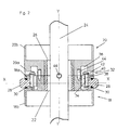
- the clasp shown in Figure 7 differs from the previous in that at its end, the blade 24 is secured to the body 20 by any suitable means, only the element 18 being able to slide on it. In this case, no stroke limiting means is necessary in the middle of the blade.
- the blade 24 is made in two parts 24a and 24b shaped so as to telescopically fit one into the other.
- the half-blade 24a is made integral with the element 18 but can slide in the element 20 to occupy, at the end of the race, when the bracelet is completely closed, the position shown in dotted lines.
- the half-blade 24b is made integral with the element 20 but can slide in the element 18 to occupy, at the end of the race, the position shown in dashed lines.
- the clasp according to the invention is both of simple construction and has a totally invisible loop. It presents especially the big advantage, compared to the sliding buckle clasp proposed in GB 680 368, already mentioned, to ensure a lock avoiding inadvertent opening of the bracelet.
Landscapes
- Buckles (AREA)
Abstract
Description
La présente invention concerne un fermoir à boucle glissante destiné à équiper un bracelet de type fermé utilisable aussi bien en horlogerie qu'en bijouterie mais aussi, plus généralement, en tant que tout type de collier destiné à être placé autour d'un corps, de manière amovible.The present invention relates to a sliding buckle clasp intended to equip a closed type bracelet that can be used both in watchmaking and jewelery but also, more generally, as any type of collar intended to be placed around a body, removable way.
Les bracelets sont soit de type ouvert, lorsque leurs deux brins peuvent être complètement séparés, soit de type fermé, lorsque les brins restent solidaires et sont reliés l'un à l'autre par une boucle permettant d'augmenter leur diamètre afin de pouvoir y passer la main.The bracelets are either open type, when their two strands can be completely separated, or closed type, when the strands remain attached and are connected to each other by a loop to increase their diameter in order to be able to to hand over.
Les bracelets de ce deuxième type, auxquels l'invention s'applique, utilisent le plus souvent une boucle, dite déployante, qui comporte généralement un fermoir à deux lames articulées. En position fermée, les lames sont maintenues repliées l'une sur l'autre. L'actionnement du fermoir autorise leur déploiement et donc l'élargissement du bracelet.The bracelets of this second type, to which the invention applies, most often use a so-called folding buckle, which generally comprises a clasp with two articulated blades. In the closed position, the blades are kept folded over one another. The operation of the clasp allows their deployment and thus the enlargement of the bracelet.
Certaines réalisations de bracelets de type fermé, moins fréquentes, utilisent une boucle, dite glissante, comme proposé dans le document GB 680 368. La boucle comporte alors une lame flexible montée fixe dans l'un des deux brins par sa première extrémité, et coulissante dans l'autre brin par sa deuxième extrémité. Une telle structure, quelque peu rudimentaire, évite, certes, la complication d'une boucle déployante, mais elle ne garantit pas que les deux brins resteront réunis en cas d'importante sollicitation du bracelet dont une ouverture intempestive est donc possible.Some embodiments of closed type bracelets, less frequent use a so-called sliding loop, as proposed in GB 680 368. The loop then comprises a flexible blade fixedly mounted in one of the two strands by its first end, and sliding in the other strand by its second end. Such a structure, somewhat rudimentary, avoids, admittedly, the complication of a folding clasp, but it does not guarantee that the two strands will remain together in case of significant stress on the bracelet which untimely opening is possible.
La présente invention a donc pour but de proposer une version améliorée d'un fermoir de bracelet à boucle glissante, exempt notamment de l'inconvénient susmentionné.The object of the present invention is therefore to propose an improved version of a sliding-loop bracelet clasp, in particular without the aforementioned drawback.
De façon plus précise, l'invention concerne un fermoir de bracelet, caractérisé en ce qu'il comporte :
- deux éléments de fermeture respectivement disposés aux deux extrémités du bracelet qui doivent être réunies et dotés de moyens permettant leur accouplement ; et
- une lame reliant lesdits éléments et montée coulissante dans au moins l'un d'eux.
- two closure elements respectively arranged at both ends of the bracelet which must be joined and provided with means for their coupling; and
- a blade connecting said elements and slidably mounted in at least one of them.
Le fermoir selon l'invention présente encore les principales caractéristiques suivantes, prises séparément ou en combinaison.
- La partie avant de chaque élément possède un canal dans lequel la lame peut se mouvoir librement, alors que sa partie arrière constitue un logement dans lequel une extrémité du bracelet peut être fixée.
- Les moyens d'accouplement des deux éléments de fermeture comportent deux poussoirs montés face à face dans la partie avant de l'un d'eux et servant à actionner chacun une griffe destinée à s'accrocher dans un logement ménagé à la partie avant de l'autre.
- La griffe comporte un corps semi-tubulaire capable de se déplacer sous l'action d'un poussoir, servant de berceau à une lamelle ressort circulaire et se prolongeant par un crochet extérieur destiné à s'arrimer dans un logement ménagé dans l'élément opposé.
- The front part of each element has a channel in which the blade can move freely, while its rear part is a housing in which one end of the bracelet can be fixed.
- The coupling means of the two closure elements comprise two pushers mounted face-to-face in the front part of one of them and each serving to actuate a claw for catching in a housing provided in the front part of the housing. 'other.
- The claw comprises a semi-tubular body capable of moving under the action of a pusher, serving as a cradle for a circular spring leaf and extending by an outer hook for docking in a housing formed in the opposite element .
D'autres caractéristiques ressortiront de la description qui va suivre, faite en regard du dessin annexé dans lequel :
- la figure 1 est une vue en perspective d'un bracelet équipé du fermoir selon l'invention, en position ouverte;
- la figure 2 est une vue de dessus en coupe selon AA du fermoir en position fermée ;
- la figure 3a est une vue agrandie en plan de son mécanisme de commande, alors que la figure 3b le représente vu de dessus ; et
- les figures 4, 5, 6, 7 et 8 illustrent divers modes de réalisation du fermoir.
- Figure 1 is a perspective view of a bracelet equipped with the clasp according to the invention, in the open position;
- Figure 2 is a top view in section along AA of the clasp in the closed position;
- Figure 3a is an enlarged plan view of its control mechanism, while Figure 3b shows it from above; and
- Figures 4, 5, 6, 7 and 8 illustrate various embodiments of the clasp.
Un bracelet possédant un fermoir à boucle glissante selon l'invention, en position ouverte, est représenté sur la figure 1 en montrant seulement qu'il comporte deux brins 10 et 12. Il est entendu que, pour une application horlogère, il s'agit effectivement de deux brins distincts dont les extrémités respectives 14 et 16 sont adaptées pour se connecter à une boîte de montre par tout moyen connu de l'homme de métier. En revanche, pour une application à la bijouterie, le bracelet peut comporter soit un seul brin, soit deux brins réunis par une articulation centrale. Le bracelet représenté est à maillons, mais il peut être monobloc, notamment en matière synthétique.A bracelet having a sliding buckle clasp according to the invention, in the open position, is shown in Figure 1 showing only that it comprises two
L'invention porte essentiellement sur le fermoir qui permet d'accoupler les extrémités du bracelet opposées aux extrémités 14 et 16.The invention relates essentially to the clasp which allows to couple the ends of the bracelet opposite to the
Les figures 1 et 2 montrent que les deux brins 10 et 12 sont fixés, par leurs extrémités respectives, à deux éléments 18 et 20 qui constituent le fermoir proprement dit du bracelet et ont la même forme extérieure, généralement parallélépipédique. Le matériau utilisé est au choix du constructeur parmi tous les matériaux connus dans le domaine, tels que le titane, l'acier, le platine, la céramique ou une matière synthétique.Figures 1 and 2 show that the two
Chacun des éléments 18 et 20 comporte une partie avant destinée à rejoindre la partie avant de l'autre, et une partie arrière à laquelle est attachée l'extrémité d'un brin du bracelet.Each of the
L'élément 18 constitue la moitié active du fermoir. Sa partie avant 18a possède un mince canal rectangulaire 22 dans lequel peut se mouvoir librement une lame 24, flexible ou rigide, avantageusement réalisée en acier, carbone, kevlar, plastique, or ou platine et décrite plus loin en détail. La partie arrière 18b constitue un logement dans lequel une extrémité du bracelet peut être fixée par vis, par barrette ou par tout autre moyen à disposition de l'homme de métier.
L'élément 20 constitue la moitié passive du fermoir. Sa partie avant 20a possède un mince canal 26, identique au canal 22, dans lequel peut également se mouvoir librement la lame 24. La partie arrière 20b constitue un logement dans lequel l'autre extrémité du bracelet peut être fixée de la même manière que mentionnée ci-dessus.The
La lame 24 pénètre ensuite, par ses extrémités, dans les deux brins 10 et 12 du bracelet qui doivent donc être aménagés pour la recevoir et la laisser coulisser librement.The
Pour permettre l'accouplement des deux éléments du fermoir, l'élément actif 18 reçoit, dans sa partie avant 18a, deux poussoirs 28 alignés face à face selon un axe transversal XX perpendiculaire à l'axe longitudinal YY du bracelet et logés dans des ouvertures ménagées dans les faces latérales du corps 18. Un joint torique 30 sert à éviter l'accumulation de salissures dans l'élément 18.To enable coupling of the two elements of the clasp, the
Comme le montre aussi le figure 3, les poussoirs 28 servent à actionner chacun une griffe 32 formée d'un corps semi-tubulaire 34 capable de se déplacer selon l'axe XX dans un logement cylindrique 36 d'axe parallèle à YY. Le poussoir 28 agit sur le milieu de la face externe du corps 34. Celui-ci sert de berceau à une lamelle ressort circulaire 38 ouverte du côté opposé au poussoir et se prolonge, hors du logement 36, par un crochet 40 sortant de la face avant de l'élément 18.As also shown in Figure 3, the
De son côté, l'élément passif 20 du fermoir possède, dans sa face avant, deux logements 42 conformés et dimensionnés pour recevoir les crochets 40 de l'élément actif 18.For its part, the
Afin de faciliter l'accouplement des deux moitiés du fermoir, l'élément 18 possède, sur sa face avant, deux goupilles de guidage 44 prenant place dans des logements ménagés dans le face avant de l'élément 20.In order to facilitate the coupling of the two halves of the clasp, the
Ainsi, pour accoupler les deux moitiés du fermoir, il suffit de les amener face à face, en s'aidant des goupilles de guidage 44. L'actionnement simultané des deux poussoirs 28 permet alors de comprimer les lames ressorts 38 contre la paroi des logements 36 et de déplacer ainsi les griffes 32 vers l'intérieur, de manière à laisser leurs crochets 40 pénétrer dans les logements 42. Le relâchement des poussoirs 28 fait revenir les ressorts 38 à leur position de repos en déplaçant les griffes 32 vers l'extérieur, de sorte que les crochets 40 s'arriment à l'élément 20 dans les logements 42. Le bracelet est ainsi fermé et verrouillé.Thus, to couple the two halves of the clasp, simply bring them face to face, with the help of the
A l'inverse, pour ouvrir le bracelet, il suffit d'enfoncer à nouveau les deux poussoirs 28 qui, en comprimant les ressorts 38, permettent de dégager les crochets 40 de leurs logements 42. Les deux moitiés du fermoir peuvent alors être séparées.Conversely, to open the bracelet, simply push the two
On se référera maintenant à la figure 4 qui représente une première forme de réalisation possible du fermoir selon l'invention, les brins du bracelet n'étant pas montrés. Sur cette figure, comme pour les figures suivantes, on retrouvera les éléments déjà décrits, affectés des mêmes numéros de référence.Referring now to Figure 4 which shows a first possible embodiment of the clasp according to the invention, the strands of the bracelet is not shown. In this figure, as for the following figures, we find the elements already described, assigned the same reference numbers.
La lame 24, qui est maintenant montrée sur toute sa longueur, est plate et se termine, à ses deux extrémités, par une portion recourbée 46 qui vient en butée contre l'entrée du canal 22 ou 26 respectivement de l'élément 18 ou 20, et ne peut y pénétrer, limitant ainsi la course des deux moitiés du fermoir (c'est-à-dire l'ouverture du bracelet) et évitant que celles-ci se désolidarisent de la lame. Celle-ci possède, en son milieu, un rivet 48 (aussi visible sur les figures 1 et 2) qui, comme les portions d'extrémité recourbées 46, ne peut pénétrer dans les canaux 22 et 26, assurant ainsi la même course à chaque moitié du fermoir.The
Les portions recourbées 46 et le rivet 48 ne sont que des exemples de moyens servant à limiter les déplacements relatifs des deux moitiés du fermoir par rapport à la lame 24. Tout autre système ayant le même effet est, bien entendu, utilisable dans le cadre de l'invention.The
La lame 24 montrée sur les figures précédemment décrites est plate, mais elle pourrait aussi, comme le montre la figure 5, être profilée, en longueur et en largeur, de toute manière qui la rendrait plus ou moins rigide et/ou plus ou moins allégée, notamment au moyen de découpes 50 et de nervures latérales 52.The
La figure 6 illustre un mode de réalisation dans lequel la lame est une chaîne formée de maillons articulés 54 qui, par l'effet esthétique procuré, rehaussent le caractère haut de gamme du bracelet.Figure 6 illustrates an embodiment in which the blade is a chain of articulated
Le fermoir représenté à la figure 7 se distingue des précédents par le fait qu'à son extrémité, la lame 24 est rendue solidaire du corps 20 par tout moyen approprié, seul l'élément 18 étant capable de coulisser sur elle. Dans ce cas, aucun moyen limiteur de course n'est nécessaire au milieu de la lame.The clasp shown in Figure 7 differs from the previous in that at its end, the
Enfin, dans le fermoir de la figure 8, la lame 24 est réalisée en deux parties 24a et 24b conformées de manière à s'emboîter télescopiquement l'une dans l'autre. Dans ce cas, la demi-lame 24a est rendue solidaire de l'élément 18 mais peut coulisser dans l'élément 20 pour occuper, en fin de course, lorsque le bracelet est complètement fermé, la position représentée en pointillés. De manière symétrique, la demi-lame 24b est rendue solidaire de l'élément 20 mais peut coulisser dans l'élément 18 pour occuper, en fin de course, la position représentée en pointillés.Finally, in the clasp of Figure 8, the
Ainsi est proposé un fermoir de bracelet à boucle glissante qui ne souffre pas de la complexité des fermoirs à boucle déployante. Le fermoir selon l'invention est, à la fois, de construction simple et doté d'une boucle totalement invisible. Il présente surtout le gros avantage, par rapport au fermoir à boucle glissante proposé dans le document GB 680 368, déjà mentionné, de garantir un verrouillage évitant toute ouverture intempestive du bracelet.Thus is proposed a sliding buckle bracelet clasp that does not suffer from the complexity of clasps folding clasp. The clasp according to the invention is both of simple construction and has a totally invisible loop. It presents especially the big advantage, compared to the sliding buckle clasp proposed in GB 680 368, already mentioned, to ensure a lock avoiding inadvertent opening of the bracelet.
Claims (12)
Priority Applications (5)
| Application Number | Priority Date | Filing Date | Title |
|---|---|---|---|
| EP04405663A EP1652443A1 (en) | 2004-10-28 | 2004-10-28 | Bracelet fastener with gliding buckle |
| PCT/EP2005/055635 WO2006045842A1 (en) | 2004-10-28 | 2005-10-28 | Bracelet clasp comprising a sliding catch |
| EP05810953A EP1816923A1 (en) | 2004-10-28 | 2005-10-28 | Bracelet fastener with gliding buckle |
| US11/718,044 US20090133438A1 (en) | 2004-10-28 | 2005-10-28 | Bracelet clasp comprising a sliding catch |
| JP2007538431A JP2008517685A (en) | 2004-10-28 | 2005-10-28 | Bracelet clasp with sliding latch |
Applications Claiming Priority (1)
| Application Number | Priority Date | Filing Date | Title |
|---|---|---|---|
| EP04405663A EP1652443A1 (en) | 2004-10-28 | 2004-10-28 | Bracelet fastener with gliding buckle |
Publications (1)
| Publication Number | Publication Date |
|---|---|
| EP1652443A1 true EP1652443A1 (en) | 2006-05-03 |
Family
ID=34932335
Family Applications (2)
| Application Number | Title | Priority Date | Filing Date |
|---|---|---|---|
| EP04405663A Withdrawn EP1652443A1 (en) | 2004-10-28 | 2004-10-28 | Bracelet fastener with gliding buckle |
| EP05810953A Withdrawn EP1816923A1 (en) | 2004-10-28 | 2005-10-28 | Bracelet fastener with gliding buckle |
Family Applications After (1)
| Application Number | Title | Priority Date | Filing Date |
|---|---|---|---|
| EP05810953A Withdrawn EP1816923A1 (en) | 2004-10-28 | 2005-10-28 | Bracelet fastener with gliding buckle |
Country Status (4)
| Country | Link |
|---|---|
| US (1) | US20090133438A1 (en) |
| EP (2) | EP1652443A1 (en) |
| JP (1) | JP2008517685A (en) |
| WO (1) | WO2006045842A1 (en) |
Cited By (1)
| Publication number | Priority date | Publication date | Assignee | Title |
|---|---|---|---|---|
| CN112971290A (en) * | 2021-03-05 | 2021-06-18 | 歌尔科技有限公司 | Watchband and wearable equipment |
Families Citing this family (15)
| Publication number | Priority date | Publication date | Assignee | Title |
|---|---|---|---|---|
| FR2944678A1 (en) * | 2009-04-27 | 2010-10-29 | Michel Louis Marie Gigoux | Extensible clasp for bracelet of wrist-watch strap or necklace, has closing elements equipped with coupling units, where end of cable is rolled on pulley positioned in one of closing elements |
| EP2502515B1 (en) * | 2011-03-21 | 2013-09-04 | The Swatch Group Management Services AG | Bracelet clasp |
| EP3626097A1 (en) | 2013-03-15 | 2020-03-25 | Apple Inc. | Attachment apparatuses and associated methods of use and manufacture |
| US10016029B2 (en) | 2014-08-09 | 2018-07-10 | Apple Inc. | Attachment systems for electronic devices |
| US10182623B2 (en) | 2014-08-11 | 2019-01-22 | Apple Inc. | Consumer product attachment systems having locking or expansion characteristics |
| US10085523B2 (en) | 2014-08-11 | 2018-10-02 | Apple Inc. | Attachment system for an electronic device |
| US10184506B2 (en) | 2014-08-11 | 2019-01-22 | Apple Inc. | Captive elements of an attachment system |
| US9949537B2 (en) | 2015-03-06 | 2018-04-24 | Apple Inc. | Clasp mechanism for wrist-worn devices |
| US10064460B2 (en) | 2015-09-30 | 2018-09-04 | Apple Inc. | Frictional stabilization of band and securement mechanism |
| US10219591B2 (en) | 2016-03-21 | 2019-03-05 | Apple Inc. | Attachment system for an electronic device |
| EP3266333B1 (en) * | 2016-07-07 | 2019-05-22 | The Swatch Group Research and Development Ltd. | Watch and piece of jewellery with interchangeable band |
| US10149518B1 (en) | 2016-08-08 | 2018-12-11 | Apple Inc. | Clasp assembly for a wearable device |
| FR3093897A1 (en) | 2019-03-20 | 2020-09-25 | Michel Gigoux | Folding clasp with rigid parallel spars |
| FR3094873A1 (en) | 2019-04-09 | 2020-10-16 | Michel Gigoux | mini folding clasp with rigid spars |
| WO2022227898A1 (en) * | 2021-04-29 | 2022-11-03 | Oppo广东移动通信有限公司 | Detachable structure, wearable device, watch band, and watch head |
Citations (3)
| Publication number | Priority date | Publication date | Assignee | Title |
|---|---|---|---|---|
| US2751132A (en) * | 1953-03-09 | 1956-06-19 | Myerson Simon | Expansible wrist watch band |
| GB1261027A (en) * | 1968-10-21 | 1972-01-19 | C P S Jewellery Company Ltd | Bracelets |
| GB1268648A (en) * | 1969-02-11 | 1972-03-29 | Excalibur Jewellery Ltd | Improvements relating to bracelets |
Family Cites Families (2)
| Publication number | Priority date | Publication date | Assignee | Title |
|---|---|---|---|---|
| US1711985A (en) * | 1926-10-13 | 1929-05-07 | Harold O Bigney | Watch bracelet |
| EP0847045A1 (en) * | 1996-12-03 | 1998-06-10 | SMH Management Services AG | Partially extensible bracelet |
-
2004
- 2004-10-28 EP EP04405663A patent/EP1652443A1/en not_active Withdrawn
-
2005
- 2005-10-28 US US11/718,044 patent/US20090133438A1/en not_active Abandoned
- 2005-10-28 WO PCT/EP2005/055635 patent/WO2006045842A1/en active Application Filing
- 2005-10-28 EP EP05810953A patent/EP1816923A1/en not_active Withdrawn
- 2005-10-28 JP JP2007538431A patent/JP2008517685A/en not_active Withdrawn
Patent Citations (3)
| Publication number | Priority date | Publication date | Assignee | Title |
|---|---|---|---|---|
| US2751132A (en) * | 1953-03-09 | 1956-06-19 | Myerson Simon | Expansible wrist watch band |
| GB1261027A (en) * | 1968-10-21 | 1972-01-19 | C P S Jewellery Company Ltd | Bracelets |
| GB1268648A (en) * | 1969-02-11 | 1972-03-29 | Excalibur Jewellery Ltd | Improvements relating to bracelets |
Cited By (1)
| Publication number | Priority date | Publication date | Assignee | Title |
|---|---|---|---|---|
| CN112971290A (en) * | 2021-03-05 | 2021-06-18 | 歌尔科技有限公司 | Watchband and wearable equipment |
Also Published As
| Publication number | Publication date |
|---|---|
| WO2006045842A1 (en) | 2006-05-04 |
| US20090133438A1 (en) | 2009-05-28 |
| JP2008517685A (en) | 2008-05-29 |
| EP1816923A1 (en) | 2007-08-15 |
Similar Documents
| Publication | Publication Date | Title |
|---|---|---|
| WO2006045842A1 (en) | Bracelet clasp comprising a sliding catch | |
| EP1790247B1 (en) | Device for adjusting the length of a wristband, wristband having such a device, and watch provided with such a wristband | |
| EP0913106B1 (en) | Foldable fastener for a bracelet | |
| WO2012095686A1 (en) | Deployment clasp for a strap, in particular a watch strap | |
| EP1836917B1 (en) | Length adjustable wristband | |
| EP2120627A1 (en) | Bracelet clasp with length adjustment device | |
| EP0661938B1 (en) | Unfolding buckle-type clasp for a bracelet | |
| EP1925227A1 (en) | Unfolding clasp for bracelets | |
| FR2751516A1 (en) | DEPLOYMENT BUCKLE CLASP | |
| EP0914781A1 (en) | Folding fastener for a bracelet | |
| CH667979A5 (en) | Adjustable fastener for bracelet - has curved central plate having groove in which arm of one part slides and locks in notches in groove | |
| CH694393A5 (en) | Wristlet end fixing device for watch case, has supports moving freely and connected to insert through canals to drive supports in axial movement, by moving insert in direction different from movement of supports | |
| EP0999765B1 (en) | Unfolding clasp for wrist band | |
| FR3058030B1 (en) | SECURE LOOP | |
| EP1785784A2 (en) | Device for fixing a watch bracelet | |
| EP0319461A1 (en) | Locking device for a bracelet | |
| EP3897273B1 (en) | Folding buckle clasp for bracelet | |
| FR2664139A1 (en) | Adjustable fastening device for the shoulder straps or the belt of a rucksack | |
| EP0867132B1 (en) | Automatic closing device for watch bands | |
| EP0046123A1 (en) | Fastener for chains, necklaces or bracelets | |
| CH716147B1 (en) | Folding clasp. | |
| WO2023170128A1 (en) | Clasp with folding buckle | |
| CH719481A2 (en) | DEPLOYANT CLASP. | |
| CH719306A2 (en) | Bracelet clasp. | |
| EP3918945A1 (en) | Watch strap and device for attaching such a strap |
Legal Events
| Date | Code | Title | Description |
|---|---|---|---|
| PUAI | Public reference made under article 153(3) epc to a published international application that has entered the european phase |
Free format text: ORIGINAL CODE: 0009012 |
|
| AK | Designated contracting states |
Kind code of ref document: A1 Designated state(s): AT BE BG CH CY CZ DE DK EE ES FI FR GB GR HU IE IT LI LU MC NL PL PT RO SE SI SK TR |
|
| AX | Request for extension of the european patent |
Extension state: AL HR LT LV MK |
|
| AKX | Designation fees paid | ||
| REG | Reference to a national code |
Ref country code: DE Ref legal event code: 8566 |
|
| STAA | Information on the status of an ep patent application or granted ep patent |
Free format text: STATUS: THE APPLICATION IS DEEMED TO BE WITHDRAWN |
|
| 18D | Application deemed to be withdrawn |
Effective date: 20061104 |