EP1630662A1 - Printer and printer control method - Google Patents
Printer and printer control method Download PDFInfo
- Publication number
- EP1630662A1 EP1630662A1 EP05018584A EP05018584A EP1630662A1 EP 1630662 A1 EP1630662 A1 EP 1630662A1 EP 05018584 A EP05018584 A EP 05018584A EP 05018584 A EP05018584 A EP 05018584A EP 1630662 A1 EP1630662 A1 EP 1630662A1
- Authority
- EP
- European Patent Office
- Prior art keywords
- buffer
- printer
- data
- host computer
- Prior art date
- Legal status (The legal status is an assumption and is not a legal conclusion. Google has not performed a legal analysis and makes no representation as to the accuracy of the status listed.)
- Granted
Links
Images


Classifications
-
- G—PHYSICS
- G06—COMPUTING; CALCULATING OR COUNTING
- G06F—ELECTRIC DIGITAL DATA PROCESSING
- G06F3/00—Input arrangements for transferring data to be processed into a form capable of being handled by the computer; Output arrangements for transferring data from processing unit to output unit, e.g. interface arrangements
- G06F3/12—Digital output to print unit, e.g. line printer, chain printer
- G06F3/1201—Dedicated interfaces to print systems
- G06F3/1223—Dedicated interfaces to print systems specifically adapted to use a particular technique
- G06F3/1229—Printer resources management or printer maintenance, e.g. device status, power levels
- G06F3/1234—Errors handling and recovery, e.g. reprinting
-
- G—PHYSICS
- G06—COMPUTING; CALCULATING OR COUNTING
- G06F—ELECTRIC DIGITAL DATA PROCESSING
- G06F3/00—Input arrangements for transferring data to be processed into a form capable of being handled by the computer; Output arrangements for transferring data from processing unit to output unit, e.g. interface arrangements
- G06F3/12—Digital output to print unit, e.g. line printer, chain printer
- G06F3/1201—Dedicated interfaces to print systems
- G06F3/1202—Dedicated interfaces to print systems specifically adapted to achieve a particular effect
- G06F3/121—Facilitating exception or error detection and recovery, e.g. fault, media or consumables depleted
Definitions
- the present invention relates generally to a printer and a printer control method, and relates more particularly to an internal process of a printer when slip printing is resumed after printing has stopped because there is no paper.
- the printer In a printer system having a printer, the printer is typically connected to enable communication with a host computer that generates the print data to be printed and controls printer operations. During printing, for example, the printer executes print control commands received from the host computer to print on slips or roll paper and then output the result.
- the printer continues printing the unprinted data. When printing thus resumes, the remaining print data that was not printed before the out-of-paper error occurred and printing stopped is printed on the new slip.
- the result is that the content that should be printed on a single slip is printed on two slips, and the resulting printed output could be rendered meaningless for the intended purpose if the content thus printed on two separate slips should have been printed on a single slip, such as when printing a sales receipt.
- the same print data must be sent from the host computer to the printer again and reprinted, resulting in wasteful paper consumption. The result is a significant drop in printing efficiency and thus reduced productivity considering the time and effort required to reprint the same content and the printing waste after printing resumes.
- JP-A-H11-268384 teaches a printer which receives from the host computer a command instructing the printer what process to execute when the printer returns from an off-line to an on-line state, and the printer thus runs a process determined by the cause of the off-line state when the printer goes back on-line. This printer can thus be prevented from printing the remaining portion of a receipt that will most likely be unusable.
- JP-A-2001-180052 teaches a printer which can select whether to store or to automatically discard new print data received while the printer is off-line. When the received data is automatically destroyed with this printer, additional data is not stored in the receive buffer while the printer is off-line, and the receive buffer will thus not become full.
- JP-A-H11-268384 and JP-A-2001-180052 describe in detail a process for returning from an off-line state to an on-line state, but are silent regarding the process for recovering from an out-of-paper error.
- the same process used to return from an off-line state to an on-line state cannot be used when printing stops due to an out-of-paper error because the printer remains in an on-line state and does not switch from an on-line state to an off-line state when an out-of-paper error occurs. Additional consideration is therefore needed to determine the best routine for resuming printing after an out-of-paper error occurs.
- a printer has a data receiving unit for receiving data sent from a host computer; a data transmission unit for sending data to the host computer; a receive buffer for temporarily storing data received by the data receiving unit; an interpreting unit for interpreting data temporarily stored in the receive buffer; a print buffer for storing a print image when the buffered data is print data; a print mechanism for printing the print image stored in the print buffer; and a control unit for controlling the data receiving unit, the data transmission unit, the receive buffer, the interpreting unit, the print buffer, and the print mechanism.
- the control unit clears data from the receive buffer when an out-of-paper error occurs and printing stops, and reports the out-of-paper error and printing stop to the host computer. When a clear buffer command is then received from the host computer, the control unit clears the receive buffer again.
- control unit clears the receive buffer and the print buffer, and clears the print buffer again according to the clear buffer command.
- control unit sends a buffer clearing completion report to the host computer after receiving the clear buffer command, and prints based on print data received from the host computer after the buffer clearing completion report is sent.
- a printer control method has steps of: clearing a receive buffer when an out-of-paper error occurs and printing stops; reporting the out-of-paper error and print stoppage to a host computer; and clearing the receive buffer again according to a clear buffer command received from the host computer.
- this printer control method also has a step of clearing a print buffer when the out-of-paper error occurs and printing stops, and then clearing the print buffer again according to the clear buffer command.
- this printer control method also has steps of: sending a buffer clearing completion report to the host computer after receiving the clear buffer command; and printing based on print data received from the host computer after the buffer clearing completion report is sent.
- An advantage of at least one embodiment of the present invention is that both the receive buffer and the print buffer are cleared of any remaining print data if an out-of-paper error occurs while printing is in progress and the printer thus stops printing. Furthermore, if print data is then received before the printer is ready to resume printing, the receive buffer and the print buffer are cleared again. As a result, no unnecessary print data remains in the printer when the printer becomes able to print again. The latter portion of the previous print data that should not be printed alone as a result of a printing stoppage due to an out-of-paper error will thus not be printed after the next slip is inserted, and a slip will thus not be wasted.
- the host computer then resends the print data for which printing was interrupted to the printer from the beginning of the print data, thus enabling the printer to smoothly and continuously print the print data to a single slip of the correct size.
- the present invention thus also advantageously minimizes the drop in efficiency and resumes printing data continuously to a single slip when printing has been interrupted due to an out-of-paper error while printing is in progress.
- a further advantage of the present invention in a printer requiring ink or toner for printing is that the useful service life of the ink cartridge or toner cartridge can be extended because the consumption of ink or toner is thus also reduced in addition to reducing paper consumption.
- a printer system 1 includes a printer 10 and a host computer 30 controlling the printer 10.
- the printer 10 is a hybrid device capable of printing both sides of a slip S, scanning the slip S, reading magnetic ink characters on the slip S, and printing a receipt to roll paper P.
- the printer 10 has a front cover 13 attached openably and closably to the main unit 11 so as to cover the front top part of the main unit 11, and a back cover 12 attached openably and closably so as to cover the top rear portion of the front cover 13.
- a roll paper compartment is formed between the back cover 12 and the main unit 11 of the printer 10.
- Roll paper P is held in this roll paper compartment.
- the roll paper P is printed by a print head not shown while being advanced through a roll paper transportation path rendered inside the main unit 11.
- the printed roll paper P is then discharged from a roll paper exit 12a formed in the top of the back cover 12.
- the leading end of the roll paper P is shown discharged from the roll paper exit 12a in Fig. 1.
- This roll paper P is cut either automatically or manually according to the length of the print data and then issued as a single receipt.
- a slip insertion slot 15 for inserting slip S is formed below the front cover 13 of the printer 10.
- a slip S inserted into the slip insertion slot 15 is conveyed through the slip transportation path 16 formed in the main unit 11, and is discharged from a slip exit 17 formed between the front cover 13 and back cover 12.
- the slip S can be printed and scanned, and magnetic ink characters printed on the slip S can be read, while the slip S is conveyed through the slip transportation path 16.
- a slip S inserted into the slip transportation path 16 is conveyed to a back printing unit 23, which is disposed at the slip transportation path 16 downstream from the slip insertion slot 15, by a slip feed subroller 22a and a slip feed pressure roller 22b disposed opposite the slip feed subroller 22a with the slip transportation path 16 therebetween.
- the back printing unit 23 is composed of a serial impact dot matrix print unit 23a disposed facing the back side of the slip S, and a platen 23b disposed opposite the print unit 23a with the slip transportation path 16 therebetween. This print unit 23a can thus print on the back of the slip S.
- Slip transportation roller 24a and slip pressure roller 24b disposed opposite the slip transportation roller 24a with the slip transportation path 16 therebetween convey the slip S downstream from the back printing unit 23 to the front printing unit 25 disposed on the slip transportation path 16.
- the slip feed subroller 22a and slip transportation roller 24a are rotationally driven by a stepping motor not shown.
- a stepping motor is a motor that can be controlled to turn a specific number of steps so that the motor turns a specific angle of rotation by controlling the number of pulses output to the stepping motor.
- the transportation distance of the slip S is thus known in this printer 10 from the angle of rotation of the stepping motor.
- the front printing unit 25 is composed of a serial impact dot matrix print unit 25a disposed facing the front side of the slip S, and a platen 25b disposed opposite the print unit 25a with the slip transportation path 16 therebetween. This print unit 25a can thus print on the front of the slip S.
- a slip S conveyed further downstream from the front printing unit 25 advances to the slip image scanner 26.
- the slip image scanner 26 is a contact image sensor (CIS) type of image scanner, and is positioned facing the front of the slip S.
- a pressure roller 27 is disposed opposite the slip image scanner 26 with the slip transportation path 16 therebetween.
- the pressure roller 27 has a pressure member 27a which is an elastic member for pressing the slip S onto the scanning surface 26a of the slip image scanner 26 with a specific pressure determined by the paper thickness.
- the slip image scanner 26 captures an image of the information recorded on the front of the slip S while the pressure roller 27 presses the slip S against the scanning surface 26a.
- the slip S is then discharged from the slip exit 17 after passing between the slip image scanner 26 and pressure roller 27.
- a trailing end sensor 28a is disposed at the slip insertion slot 15, and a leading end sensor 28b is disposed downstream from the slip feed pressure roller 22b.
- the trailing end sensor 28a and leading end sensor 28b are used to check if a slip S is present in the slip transportation path 16, to detect the length of the slip S, and to index the slip S for printing by the back printing unit 23 and front printing unit 25.
- a discharge detector 29 is disposed between the front printing unit 25 and the slip image scanner 26, and detects if the slip S has been discharged from the slip transportation path 16.
- a magnetic ink character recognition (MICR) sensor 20 is disposed near the slip insertion slot 15 of the slip transportation path 16. This MICR sensor 20 is used for reading magnetic ink characters printed in magnetic ink on the slip S. If the slip S is a check, for example, the magnetic ink characters typically include the number of the bank, the branch number, and the number of the account against which the check is issued, as well as a check serial number. This information can thus be read using the MICR sensor 20, enabling the printer 10 to recognize the MICR data on an inserted check.
- MICR magnetic ink character recognition
- a printer 10 according to this embodiment of the invention also has a CPU and internal memory.
- the CPU reads and runs firmware stored in nonvolatile memory such as a flash ROM, for example, to control printer operations, including printing. Control of this printer 10 is described more specifically below.
- the host computer 30 is described first next.
- the host computer 30 is connected by a serial cable, USB cable, or other communication cable 500. Although not shown, the printer and the host computer could alternatively be connected to communicate wirelessly.
- the host computer 30 in this embodiment of the invention has input devices such as a touch panel 31 and card reader 32, generates print data based on input from the touch panel 31 and card reader 32, and sends the resulting print data to the printer 10 over the communication cable 500. The printer 10 then prints on roll paper or a slip based on this print data.
- a host computer having a touch panel 31 and card reader 32 is used by way of example in the present embodiment of the invention. Any device capable of controlling the printer 10 can be used instead, and the host computer could be based on a common personal computer, for example.
- the printer 10 has an internal data receiving unit 41, receive buffer 42, command interpreter 43, control unit 44, print buffer 45, print mechanism 46, leading end detection unit 47, trailing end detection unit 48, paper length detection unit 50, regular status data generating unit 51, status data comparison unit 52, status data storage unit 53, and data transmission unit 54.
- the data receiving unit 41 is a data communication unit for receiving print data and commands sent from the host computer 30, and includes a communication interface. The data receiving unit 41 sequentially stores the received data in the receive buffer.
- the receive buffer 42 is a data storage unit, which can be a line buffer or ring buffer type, and stores the data received by the data receiving unit 41 in the order received.
- the command interpreter 43 reads the data stored in the receive buffer 42 in a first-in, first-out (FIFO) sequence and interprets the content. If the received data is print data, the print data is converted to a bitmap image in the print buffer 45 with reference to a font ROM, for example. If the received data is a control command for the printer 10, the control unit 44 controls the other function units according to the command content and thus provides overall control of the printer 10. Based on the paper length detected by the paper length detection unit 50 described below, the control unit 44 decides whether to stop printing due to an out-of-paper error.
- FIFO first-in, first-out
- the print mechanism 46 is a printing unit for driving transportation rollers not shown to advance the paper while driving a print head to print.
- the print mechanism 46 renders paper transportation control and print head control based on the print image written to print buffer 45, and thus prints to a slip S or roll paper P.
- the leading end detection unit 47 is a detection unit which detects if the leading end sensor 28b has detected the leading end of a slip S. If the leading end sensor 28b detects the leading end of a slip S, the leading end detection unit 47 outputs a paper detection signal to the paper length detection unit 50.
- the trailing end detection unit 48 is a detection unit which detects if the trailing end sensor 28a has detected the trailing end of a slip S. If the leading end sensor 28b detects the trailing end of a slip S, the trailing end detection unit 48 outputs a paper detection signal to the paper length detection unit 50.
- the paper length detection unit 50 detects the length of the slip S in the transportation direction based on the detection signal from the leading end detection unit 47, the detection signal from the trailing end detection unit 48, and the transportation distance of the slip S determined from the angle of stepping motor rotation.
- the paper length detection unit 50 calculates the length of the slip S based on the distance the slip S is conveyed between the moment at which the leading end detection unit 47 detects the leading end (the time when leading end detection unit 47 output changes from the no-paper state to the paper-detected state) and the moment at which the trailing end detection unit 48 detects the trailing end of the slip S (the time when trailing end detection unit 48 output changes from the paper-detected state to the no-paper state).
- the regular status data generating unit 51 monitors the status of an error detection unit, cover detection unit, paper detection unit, off-line detection unit, and other detection units not shown, and regularly collects and generates printer status data based on outputs from these other units.
- the regular status data generating unit 51 outputs the resulting status data to the status data comparison unit 52 as the status data is generated.
- the status data comparison unit 52 is a comparator for comparing the current status data generated by the regular status data generating unit 51 and the previous status data stored in the status data storage unit 53.
- the status data stored in the status data storage unit 53 is the previous status data produced by the regular status data generating unit 51.
- comparing this status data enables knowing if the internal status of the printer 10, which is denoted by the current status data detected when the status data was most recently monitored, has changed from the internal status of the printer 10 as denoted by the status data detected the previous time the status data was monitored.
- the status data comparison unit 52 updates the status data stored in the status data storage unit 53 to the new (current) status data, and sends the current status data as a status signal through the data transmission unit 54 to the host computer 30.
- This process is known as an Automatic Status Back (ASB) function, and this ASB function enables the host computer 30 to always know the current internal status of the printer 10.
- ASB Automatic Status Back
- a printer 10 can select the process to run when printing stops due to an out-of-paper error.
- GS J 80 m "GS (J 80" denotes the reset operation setup command relating to the process to be executed when printing stops due to an out-of-paper error.
- the argument m of this command is either 0 or 1.
- the control unit 44 runs the normal operating process.
- the reset operation setup command can be set by the host computer 30 according to the type of printing as specified by the user.
- Fig. 7 is a timing chart showing the commands communicated between the host computer and printer. The processes executed by the printer 10 and host computer 30 are described in chronological order with reference to Fig. 5, Fig. 6, and Fig. 7 below.
- step S21 When the printer 10 is on-line and the host computer 30 sends print data to the printer 10 as shown in Fig. 6 (step S21), the printer 10 receives the print data and starts printing on the slip S by means of the print mechanism 46 as shown in Fig. 5 (step S11).
- the printer 10 then continues printing the slip S while the paper length detection unit 50 detects the paper length.
- the control unit 44 compares the paper length detected by the paper length detection unit 50 with the length of the print data (such as the number of lines) received for a single continuous print job, and determines if all of the received print data can be printed on one slip S, that is, if an out-of-paper error will occur and printing will thus stop (step S12). If the length of the print data enables printing all print data on the slip S, step S12 returns NO, printing ends, and the printing process ends.
- control unit 44 determines that not all print data can be printed to the slip S
- the control unit 44 runs the process stopping printing due to an out-of-paper error while the printer remains on-line, and thus interrupts printing on the slip S (step S13).
- the control unit 44 of the printer 10 then runs the following three processes (step S14):
- the printer 10 discards any data received from the host computer 30 and stored in the receive buffer 42 just before the out-of-paper error occurred.
- the data stored in the receive buffer 42 may include unprinted data that should be printed to the slip S that was being printed when printing was interrupted, and this unprinted data is also deleted from the printer's 10 memory. This prevents printing the unprinted data left in the receive buffer 42 when printing resumes, and thus prevents printing a slip S containing only the last portion of the previously transmitted print data.
- Process (b) informs the host computer 30 that an out-of-paper error occurred and printing is stopped.
- the control unit 44 sends a response command called clear response 1 through the data transmission unit 54 to the host computer 30.
- the print image data stored in the print buffer 45 is discarded in process (c).
- Process (c) thus clears the print image from the print buffer 45 to prevent unnecessary printing.
- process (d) the command interpreting process of the command interpreter 43 is initialized, the print data being processed is thus ignored, and the command interpreter 43 is initialized to interpret the print commands received for the print data received next.
- the printer 10 then monitors whether a clear buffer command was sent as the response command to clear response 1, and the printer 10 waits until this clear buffer command is received (step S15).
- step S23 when the host computer 30 receives clear response 1 in step S22 and thus knows that the printer 10 stopped printing due to an out-of-paper error, the host computer 30 immediately interrupts sending print data and sends a clear buffer command to the printer 10 (step S23).
- the clear buffer command is a command causing the printer 10 to clear the internal receive buffer and the print buffer again.
- Clearing the buffers a second time may be considered unnecessary because the printer 10 has already cleared the receive buffer 42 and the print buffer 45 in step S14, but clearing the buffers may be necessary for the reasons described below.
- the printer 10 While no problem occurs if the printer 10 receives no print data after clearing the receive buffer 42 and print buffer 45, the printer 10 does not go off-line when an out-of-paper error occurs and thus receives and writes to the receive buffer 42 any print data that is sent from the host computer 30 after the buffer is cleared and before the host computer 30 stops sending data. If this received data is stored in the receive buffer 42, part of the last part of the print data that was not previously printed will be printed when a slip S is inserted and the out-of-paper error is cleared, and this slip S will thus be wasted.
- the receive buffer 42 and print buffer 45 are preferably cleared again after step S14.
- the clear buffer command sent in step S23 is this command for clearing the buffers.
- the host computer 30 receives a print termination command from the printer 10 each time printing one line of print data ends, and stores all of the print data that is sent or is to be sent to the printer 10 for one receipt until a print termination command indicating that the last line of the receipt being printed has been printed is received from the printer 10. As shown in Fig. 5 and Fig. 6, printing stops because of an out-of-paper error and the last line of print data is thus not printed, the print data to be printed on a slip S is saved for retransmission after the printer 10 cancels the out-of-paper error and resumes printing.
- step S15 If printer 10 receives the clear buffer command in step S15, the control unit 44 of the printer 10 executes the following four processes in step S16.
- step S16 repeats the buffer clearing and initialization operations of the process executed in step S14.
- the printer 10 then sends clear response 2 to the host computer 30 and the host computer 30 thus knows that the buffer has been cleared.
- the host computer 30 waits in step S24 to receive clear response 2, and in step S25 resends the print data starting from the first line of the interrupted print job when clear response 2 is received.
- the printer 10 thus again receives the receipt print data from the host computer 30, and waits for paper to be loaded.
- a slip S of the appropriate size is then inserted into the slip insertion slot 15, the printer 10 reprints the slip S from the beginning of the print data.
- a printer 10 has a data receiving unit 41 for receiving data sent from a host computer 30, a data transmission unit 54 for sending data to the host computer 30, a receive buffer 42 for temporarily storing data received by the data receiving unit 41, a command interpreter 43 for interpreting data temporarily stored in the receive buffer 42, a print buffer 45 for storing print image data when the data interpreted by the command interpreter 43 is print data, a print mechanism 46 for printing based on the print image written to the print buffer 45, and a control unit 44 for controlling the data receiving unit 41, receive buffer 42, command interpreter 43, print buffer 45, and print mechanism 46.
- control unit 44 clears the data stored in the receive buffer 42 and sends clear response 1 to report the out-of-paper error to the host computer 30.
- the control unit 44 then clears the receive buffer 42 again according to a clear buffer command received from the host computer 30. More particularly, the control unit 44 clears the receive buffer 42 and the print buffer 45, and clears the receive buffer 42 and print buffer 45 again when a clear buffer command is received.
- the receive buffer 42 and print buffer 45 are cleared twice of the print data that was being printed and no data to be printed remains in the printer 10 when the printer 10 is again able to print.
- the remaining unprinted portion of the receipt that was being printed when the out-of-paper error occurred will thus not be printed when the printer returns to the on-line state, and a slip S will thus not be wasted.
- a single slip S can be smoothly printed because the host computer 30 resends all print data for which printing was interrupted to the printer 10. The drop in efficiency can thus be minimized and continuous printing can be resumed even if an out-of-paper error occurs during printing and printing is thus interrupted.
- the present invention has been described using by way of example a printer as shown in Fig. 1.
- the invention is not limited, however, to this particular printer and can be applied to various kinds of printers, including inkjet printers, laser printers, dot impact printers, and thermal printers.
- the present invention reduces ink and toner consumption in addition to reducing paper consumption, and thus also contributes to extending the useful service life of ink cartridges and toner cartridges.
Landscapes
- Engineering & Computer Science (AREA)
- Theoretical Computer Science (AREA)
- Human Computer Interaction (AREA)
- Physics & Mathematics (AREA)
- General Engineering & Computer Science (AREA)
- General Physics & Mathematics (AREA)
- Accessory Devices And Overall Control Thereof (AREA)
- Record Information Processing For Printing (AREA)
Abstract
Description
- The present invention relates generally to a printer and a printer control method, and relates more particularly to an internal process of a printer when slip printing is resumed after printing has stopped because there is no paper.
- In a printer system having a printer, the printer is typically connected to enable communication with a host computer that generates the print data to be printed and controls printer operations. During printing, for example, the printer executes print control commands received from the host computer to print on slips or roll paper and then output the result.
- If a slip that is too small is mistakenly inserted or more print data than can be printed on a single slip is sent to the printer when printing on a slip, an error is generated and printing stops because there is no paper to print on. Such errors are referred to herein as an "out-of-paper error". When an out-of-paper error occurs, the printer interrupts printing on the slip and waits for a new slip to be inserted.
- When a new slip is then inserted, the printer continues printing the unprinted data. When printing thus resumes, the remaining print data that was not printed before the out-of-paper error occurred and printing stopped is printed on the new slip. The result is that the content that should be printed on a single slip is printed on two slips, and the resulting printed output could be rendered meaningless for the intended purpose if the content thus printed on two separate slips should have been printed on a single slip, such as when printing a sales receipt. When this happens, the same print data must be sent from the host computer to the printer again and reprinted, resulting in wasteful paper consumption. The result is a significant drop in printing efficiency and thus reduced productivity considering the time and effort required to reprint the same content and the printing waste after printing resumes.
- JP-A-H11-268384 teaches a printer which receives from the host computer a command instructing the printer what process to execute when the printer returns from an off-line to an on-line state, and the printer thus runs a process determined by the cause of the off-line state when the printer goes back on-line. This printer can thus be prevented from printing the remaining portion of a receipt that will most likely be unusable.
- JP-A-2001-180052 teaches a printer which can select whether to store or to automatically discard new print data received while the printer is off-line. When the received data is automatically destroyed with this printer, additional data is not stored in the receive buffer while the printer is off-line, and the receive buffer will thus not become full.
- JP-A-H11-268384 and JP-A-2001-180052 describe in detail a process for returning from an off-line state to an on-line state, but are silent regarding the process for recovering from an out-of-paper error. The same process used to return from an off-line state to an on-line state cannot be used when printing stops due to an out-of-paper error because the printer remains in an on-line state and does not switch from an on-line state to an off-line state when an out-of-paper error occurs. Additional consideration is therefore needed to determine the best routine for resuming printing after an out-of-paper error occurs.
- It is an object of the present invention to provide a printer and a printer control method allowint to smoothly resuming an interrupted printing operation with no printing waste after printing stops due to an out-of-paper error.
- This object is achieved by a printer as claimed in
claim 1 and a method as claimed in claim 4. Preferred embodiments of the invention are subject-matter of the dependent claims. - A printer according to a first aspect of at least one embodiment of the present invention has a data receiving unit for receiving data sent from a host computer; a data transmission unit for sending data to the host computer; a receive buffer for temporarily storing data received by the data receiving unit; an interpreting unit for interpreting data temporarily stored in the receive buffer; a print buffer for storing a print image when the buffered data is print data; a print mechanism for printing the print image stored in the print buffer; and a control unit for controlling the data receiving unit, the data transmission unit, the receive buffer, the interpreting unit, the print buffer, and the print mechanism. The control unit clears data from the receive buffer when an out-of-paper error occurs and printing stops, and reports the out-of-paper error and printing stop to the host computer. When a clear buffer command is then received from the host computer, the control unit clears the receive buffer again.
- Preferably, the control unit clears the receive buffer and the print buffer, and clears the print buffer again according to the clear buffer command.
- Yet further, preferably, the control unit sends a buffer clearing completion report to the host computer after receiving the clear buffer command, and prints based on print data received from the host computer after the buffer clearing completion report is sent.
- A printer control method according to a second aspect of the present invention has steps of: clearing a receive buffer when an out-of-paper error occurs and printing stops; reporting the out-of-paper error and print stoppage to a host computer; and clearing the receive buffer again according to a clear buffer command received from the host computer.
- Preferably, this printer control method also has a step of clearing a print buffer when the out-of-paper error occurs and printing stops, and then clearing the print buffer again according to the clear buffer command.
- Yet further, preferably, this printer control method also has steps of: sending a buffer clearing completion report to the host computer after receiving the clear buffer command; and printing based on print data received from the host computer after the buffer clearing completion report is sent.
- An advantage of at least one embodiment of the present invention is that both the receive buffer and the print buffer are cleared of any remaining print data if an out-of-paper error occurs while printing is in progress and the printer thus stops printing. Furthermore, if print data is then received before the printer is ready to resume printing, the receive buffer and the print buffer are cleared again. As a result, no unnecessary print data remains in the printer when the printer becomes able to print again. The latter portion of the previous print data that should not be printed alone as a result of a printing stoppage due to an out-of-paper error will thus not be printed after the next slip is inserted, and a slip will thus not be wasted.
- The host computer then resends the print data for which printing was interrupted to the printer from the beginning of the print data, thus enabling the printer to smoothly and continuously print the print data to a single slip of the correct size. The present invention thus also advantageously minimizes the drop in efficiency and resumes printing data continuously to a single slip when printing has been interrupted due to an out-of-paper error while printing is in progress.
- A further advantage of the present invention in a printer requiring ink or toner for printing is that the useful service life of the ink cartridge or toner cartridge can be extended because the consumption of ink or toner is thus also reduced in addition to reducing paper consumption.
- Other objects and attainments together with a fuller understanding of the invention will become apparent and appreciated by referring to the following description of preferred embodiments taken in conjunction with the accompanying drawings, in which:
- Fig. 1
- is an perspective view showing a printer system according to a preferred embodiment of the present invention;
- Fig. 2
- is a schematic section view showing the slip S transportation path;
- Fig. 3
- is a schematic function block diagram showing the internal control configuration of the printer system shown in Fig. 1;
- Fig. 4
- is a flow chart of a printer control process;
- Fig. 5
- is a flow chart of a printer control process;
- Fig. 6
- is a flow chart of a host computer control process; and
- Fig. 7
- is a timing chart showing commands sent between the host computer and printer.
- A printer and a printer control method according to preferred embodiments of the present invention are described below with reference to the accompanying figures.
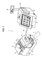
- As shown in Fig. 1, a
printer system 1 according to this embodiment of the invention includes aprinter 10 and ahost computer 30 controlling theprinter 10. Theprinter 10 is a hybrid device capable of printing both sides of a slip S, scanning the slip S, reading magnetic ink characters on the slip S, and printing a receipt to roll paper P. - The
printer 10 has afront cover 13 attached openably and closably to themain unit 11 so as to cover the front top part of themain unit 11, and aback cover 12 attached openably and closably so as to cover the top rear portion of thefront cover 13. - A roll paper compartment is formed between the
back cover 12 and themain unit 11 of theprinter 10. Roll paper P is held in this roll paper compartment. The roll paper P is printed by a print head not shown while being advanced through a roll paper transportation path rendered inside themain unit 11. The printed roll paper P is then discharged from aroll paper exit 12a formed in the top of theback cover 12. The leading end of the roll paper P is shown discharged from theroll paper exit 12a in Fig. 1. This roll paper P is cut either automatically or manually according to the length of the print data and then issued as a single receipt. - A
slip insertion slot 15 for inserting slip S is formed below thefront cover 13 of theprinter 10. A slip S inserted into theslip insertion slot 15 is conveyed through theslip transportation path 16 formed in themain unit 11, and is discharged from aslip exit 17 formed between thefront cover 13 andback cover 12. The slip S can be printed and scanned, and magnetic ink characters printed on the slip S can be read, while the slip S is conveyed through theslip transportation path 16. - As shown in Fig. 2, a slip S inserted into the
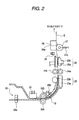
slip transportation path 16 is conveyed to aback printing unit 23, which is disposed at theslip transportation path 16 downstream from theslip insertion slot 15, by aslip feed subroller 22a and a slipfeed pressure roller 22b disposed opposite theslip feed subroller 22a with theslip transportation path 16 therebetween. - The
back printing unit 23 is composed of a serial impact dotmatrix print unit 23a disposed facing the back side of the slip S, and aplaten 23b disposed opposite theprint unit 23a with theslip transportation path 16 therebetween. Thisprint unit 23a can thus print on the back of the slip S. -
Slip transportation roller 24a and slippressure roller 24b disposed opposite theslip transportation roller 24a with theslip transportation path 16 therebetween convey the slip S downstream from theback printing unit 23 to thefront printing unit 25 disposed on theslip transportation path 16. Theslip feed subroller 22a and sliptransportation roller 24a are rotationally driven by a stepping motor not shown. A stepping motor is a motor that can be controlled to turn a specific number of steps so that the motor turns a specific angle of rotation by controlling the number of pulses output to the stepping motor. The transportation distance of the slip S is thus known in thisprinter 10 from the angle of rotation of the stepping motor. - The
front printing unit 25 is composed of a serial impact dotmatrix print unit 25a disposed facing the front side of the slip S, and aplaten 25b disposed opposite theprint unit 25a with theslip transportation path 16 therebetween. Thisprint unit 25a can thus print on the front of the slip S. - A slip S conveyed further downstream from the
front printing unit 25 advances to theslip image scanner 26. - The
slip image scanner 26 is a contact image sensor (CIS) type of image scanner, and is positioned facing the front of the slip S.A pressure roller 27 is disposed opposite theslip image scanner 26 with theslip transportation path 16 therebetween. Thepressure roller 27 has apressure member 27a which is an elastic member for pressing the slip S onto thescanning surface 26a of theslip image scanner 26 with a specific pressure determined by the paper thickness. Theslip image scanner 26 captures an image of the information recorded on the front of the slip S while thepressure roller 27 presses the slip S against thescanning surface 26a. - The slip S is then discharged from the
slip exit 17 after passing between theslip image scanner 26 andpressure roller 27. - A trailing
end sensor 28a is disposed at theslip insertion slot 15, and aleading end sensor 28b is disposed downstream from the slipfeed pressure roller 22b. The trailingend sensor 28a andleading end sensor 28b are used to check if a slip S is present in theslip transportation path 16, to detect the length of the slip S, and to index the slip S for printing by theback printing unit 23 andfront printing unit 25. - A
discharge detector 29 is disposed between thefront printing unit 25 and theslip image scanner 26, and detects if the slip S has been discharged from theslip transportation path 16. - A magnetic ink character recognition (MICR)
sensor 20 is disposed near theslip insertion slot 15 of theslip transportation path 16. ThisMICR sensor 20 is used for reading magnetic ink characters printed in magnetic ink on the slip S. If the slip S is a check, for example, the magnetic ink characters typically include the number of the bank, the branch number, and the number of the account against which the check is issued, as well as a check serial number. This information can thus be read using theMICR sensor 20, enabling theprinter 10 to recognize the MICR data on an inserted check. - A
printer 10 according to this embodiment of the invention also has a CPU and internal memory. The CPU reads and runs firmware stored in nonvolatile memory such as a flash ROM, for example, to control printer operations, including printing. Control of thisprinter 10 is described more specifically below. - The
host computer 30 is described first next. - The
host computer 30 is connected by a serial cable, USB cable, or other communication cable 500. Although not shown, the printer and the host computer could alternatively be connected to communicate wirelessly. Thehost computer 30 in this embodiment of the invention has input devices such as atouch panel 31 andcard reader 32, generates print data based on input from thetouch panel 31 andcard reader 32, and sends the resulting print data to theprinter 10 over the communication cable 500. Theprinter 10 then prints on roll paper or a slip based on this print data. - A host computer having a
touch panel 31 andcard reader 32 is used by way of example in the present embodiment of the invention. Any device capable of controlling theprinter 10 can be used instead, and the host computer could be based on a common personal computer, for example. - Internal processes of the
printer 10 are described next. - As shown in Fig. 3 the
printer 10 has an internaldata receiving unit 41, receivebuffer 42,command interpreter 43,control unit 44,print buffer 45,print mechanism 46, leadingend detection unit 47, trailingend detection unit 48, paperlength detection unit 50, regular statusdata generating unit 51, statusdata comparison unit 52, statusdata storage unit 53, anddata transmission unit 54. - The
data receiving unit 41 is a data communication unit for receiving print data and commands sent from thehost computer 30, and includes a communication interface. Thedata receiving unit 41 sequentially stores the received data in the receive buffer. - The receive
buffer 42 is a data storage unit, which can be a line buffer or ring buffer type, and stores the data received by thedata receiving unit 41 in the order received. - The
command interpreter 43 reads the data stored in the receivebuffer 42 in a first-in, first-out (FIFO) sequence and interprets the content. If the received data is print data, the print data is converted to a bitmap image in theprint buffer 45 with reference to a font ROM, for example. If the received data is a control command for theprinter 10, thecontrol unit 44 controls the other function units according to the command content and thus provides overall control of theprinter 10. Based on the paper length detected by the paperlength detection unit 50 described below, thecontrol unit 44 decides whether to stop printing due to an out-of-paper error. - The
print mechanism 46 is a printing unit for driving transportation rollers not shown to advance the paper while driving a print head to print. Theprint mechanism 46 renders paper transportation control and print head control based on the print image written to printbuffer 45, and thus prints to a slip S or roll paper P. - The leading
end detection unit 47 is a detection unit which detects if theleading end sensor 28b has detected the leading end of a slip S. If theleading end sensor 28b detects the leading end of a slip S, the leadingend detection unit 47 outputs a paper detection signal to the paperlength detection unit 50. - The trailing
end detection unit 48 is a detection unit which detects if the trailingend sensor 28a has detected the trailing end of a slip S. If theleading end sensor 28b detects the trailing end of a slip S, the trailingend detection unit 48 outputs a paper detection signal to the paperlength detection unit 50. - The paper
length detection unit 50 detects the length of the slip S in the transportation direction based on the detection signal from the leadingend detection unit 47, the detection signal from the trailingend detection unit 48, and the transportation distance of the slip S determined from the angle of stepping motor rotation. - More specifically, the paper
length detection unit 50 calculates the length of the slip S based on the distance the slip S is conveyed between the moment at which the leadingend detection unit 47 detects the leading end (the time when leadingend detection unit 47 output changes from the no-paper state to the paper-detected state) and the moment at which the trailingend detection unit 48 detects the trailing end of the slip S (the time when trailingend detection unit 48 output changes from the paper-detected state to the no-paper state). - The regular status
data generating unit 51 monitors the status of an error detection unit, cover detection unit, paper detection unit, off-line detection unit, and other detection units not shown, and regularly collects and generates printer status data based on outputs from these other units. The regular statusdata generating unit 51 outputs the resulting status data to the statusdata comparison unit 52 as the status data is generated. - The status
data comparison unit 52 is a comparator for comparing the current status data generated by the regular statusdata generating unit 51 and the previous status data stored in the statusdata storage unit 53. Note that the status data stored in the statusdata storage unit 53 is the previous status data produced by the regular statusdata generating unit 51. Thus, comparing this status data enables knowing if the internal status of theprinter 10, which is denoted by the current status data detected when the status data was most recently monitored, has changed from the internal status of theprinter 10 as denoted by the status data detected the previous time the status data was monitored. - If the status data produced by the regular status
data generating unit 51 is the same as the status data previously stored in the statusdata storage unit 53, the internal status of theprinter 10 has not changed and the comparison process ends. If the previous and current status data are different, there has been a change in the internal status of theprinter 10. The statusdata comparison unit 52 therefore updates the status data stored in the statusdata storage unit 53 to the new (current) status data, and sends the current status data as a status signal through thedata transmission unit 54 to thehost computer 30. This process is known as an Automatic Status Back (ASB) function, and this ASB function enables thehost computer 30 to always know the current internal status of theprinter 10. - The processes run in this embodiment of the invention when the printer goes off-line because there is no paper is described in detail below.
- As a result of receiving a reset operation setup command (1) as shown below from the
host computer 30, aprinter 10 according to this embodiment of the invention can select the process to run when printing stops due to an out-of-paper error.
"GS (J 80" denotes the reset operation setup command relating to the process to be executed when printing stops due to an out-of-paper error. The argument m of this command is either 0 or 1. When argument m = 0, thecontrol unit 44 runs the normal operating process. When argument m = 1, thecontrol unit 44 runs a process for preventing wasting printing and paper when returning to the on-line state. More specifically, theprinter 10 runs the internal processes described below depending upon whether m = 0 or m = 1. The following processes are executed automatically when printing stops due to an out-of-paper error. - When m = 0: normal operation
- (1) Do not clear the receive buffer and the print buffer;
- (2) If a command was being processed when the out-of-paper error occurred, the corresponding command process continues.
- When m = 1: paper-saving mode
- (1) Clear the receive buffer and the print buffer;
- (2) If a command was being processed when the out-of-paper error occurred, abort the corresponding command process (and do not continue executing the command after error recovery);
- (3) Discard and do not store in the receive buffer any data received from when the out-of-paper error occurred until the printer returns on-line (this process is not part of the process returning the printer on-line);
- (4) Send a clear response to the
host computer 30. - This process is described further below with reference to Fig. 4.
- When this process starts, the
printer 10 is initially set to m = 0, and theprinter 10 changes the operating mode when the command shown in statement (1) above is received. More specifically, theprinter 10 is set to the normal operating mode based on the initial m = 0 setting (step S1), and waits to receive the reset operation setup command in step S2. - When the reset operation setup command is then received, the
printer 10 reads the value of argument m (step S3). If m = 0, the normal operating mode is reset in step S4. If m = 1, the paper-saving mode is set in step S5. The reset operation setup command can be set by thehost computer 30 according to the type of printing as specified by the user. - The paper-saving mode which is executed when m = 1 is described in detail next.
- Fig. 5 is a flow chart showing the process run by the
printer 10 in the paper-saving mode when m = 1. Fig. 6 is a flow chart showing the process run by thehost computer 30 in the paper-saving mode when m = 1. Fig. 7 is a timing chart showing the commands communicated between the host computer and printer. The processes executed by theprinter 10 andhost computer 30 are described in chronological order with reference to Fig. 5, Fig. 6, and Fig. 7 below. - When the
printer 10 is on-line and thehost computer 30 sends print data to theprinter 10 as shown in Fig. 6 (step S21), theprinter 10 receives the print data and starts printing on the slip S by means of theprint mechanism 46 as shown in Fig. 5 (step S11). - The
printer 10 then continues printing the slip S while the paperlength detection unit 50 detects the paper length. Thecontrol unit 44 compares the paper length detected by the paperlength detection unit 50 with the length of the print data (such as the number of lines) received for a single continuous print job, and determines if all of the received print data can be printed on one slip S, that is, if an out-of-paper error will occur and printing will thus stop (step S12). If the length of the print data enables printing all print data on the slip S, step S12 returns NO, printing ends, and the printing process ends. - If the
control unit 44 determines that not all print data can be printed to the slip S, thecontrol unit 44 runs the process stopping printing due to an out-of-paper error while the printer remains on-line, and thus interrupts printing on the slip S (step S13). Thecontrol unit 44 of theprinter 10 then runs the following three processes (step S14): - (a) Clear receive buffer
- (b) Report an out-of-paper error and printing interruption to the host computer (send clear response 1)
- (c) Clear the print buffer
- (d) Initialize command interpreting
- In process (a) the
printer 10 discards any data received from thehost computer 30 and stored in the receivebuffer 42 just before the out-of-paper error occurred. The data stored in the receivebuffer 42 may include unprinted data that should be printed to the slip S that was being printed when printing was interrupted, and this unprinted data is also deleted from the printer's 10 memory. This prevents printing the unprinted data left in the receivebuffer 42 when printing resumes, and thus prevents printing a slip S containing only the last portion of the previously transmitted print data. - Process (b) informs the
host computer 30 that an out-of-paper error occurred and printing is stopped. To execute this process, thecontrol unit 44 sends a response command calledclear response 1 through thedata transmission unit 54 to thehost computer 30. - The print image data stored in the
print buffer 45 is discarded in process (c). When printing stops due to an out-of-paper error while printing, an unprinted print image may remain in theprint buffer 45. Process (c) thus clears the print image from theprint buffer 45 to prevent unnecessary printing. - In process (d) the command interpreting process of the
command interpreter 43 is initialized, the print data being processed is thus ignored, and thecommand interpreter 43 is initialized to interpret the print commands received for the print data received next. - The
printer 10 then monitors whether a clear buffer command was sent as the response command toclear response 1, and theprinter 10 waits until this clear buffer command is received (step S15). - Meanwhile, as shown in Fig. 5, when the
host computer 30 receivesclear response 1 in step S22 and thus knows that theprinter 10 stopped printing due to an out-of-paper error, thehost computer 30 immediately interrupts sending print data and sends a clear buffer command to the printer 10 (step S23). - The clear buffer command is a command causing the
printer 10 to clear the internal receive buffer and the print buffer again. - Clearing the buffers a second time may be considered unnecessary because the
printer 10 has already cleared the receivebuffer 42 and theprint buffer 45 in step S14, but clearing the buffers may be necessary for the reasons described below. - While no problem occurs if the
printer 10 receives no print data after clearing the receivebuffer 42 andprint buffer 45, theprinter 10 does not go off-line when an out-of-paper error occurs and thus receives and writes to the receivebuffer 42 any print data that is sent from thehost computer 30 after the buffer is cleared and before thehost computer 30 stops sending data. If this received data is stored in the receivebuffer 42, part of the last part of the print data that was not previously printed will be printed when a slip S is inserted and the out-of-paper error is cleared, and this slip S will thus be wasted. - To prevent this problem, the receive
buffer 42 andprint buffer 45 are preferably cleared again after step S14. The clear buffer command sent in step S23 is this command for clearing the buffers. - The
host computer 30 receives a print termination command from theprinter 10 each time printing one line of print data ends, and stores all of the print data that is sent or is to be sent to theprinter 10 for one receipt until a print termination command indicating that the last line of the receipt being printed has been printed is received from theprinter 10. As shown in Fig. 5 and Fig. 6, printing stops because of an out-of-paper error and the last line of print data is thus not printed, the print data to be printed on a slip S is saved for retransmission after theprinter 10 cancels the out-of-paper error and resumes printing. - If
printer 10 receives the clear buffer command in step S15, thecontrol unit 44 of theprinter 10 executes the following four processes in step S16. - (d) Clear receive buffer;
- (e) Report cleared receive buffer (send clear response 2)
- (f) Clear print buffer
- (g) Reinitialize command interpreting
- Considering the possible presence of print data sent from the
host computer 30 after step S14 is executed, step S16 repeats the buffer clearing and initialization operations of the process executed in step S14. Theprinter 10 then sendsclear response 2 to thehost computer 30 and thehost computer 30 thus knows that the buffer has been cleared. - The
host computer 30 waits in step S24 to receiveclear response 2, and in step S25 resends the print data starting from the first line of the interrupted print job whenclear response 2 is received. - The
printer 10 thus again receives the receipt print data from thehost computer 30, and waits for paper to be loaded. When a slip S of the appropriate size is then inserted into theslip insertion slot 15, theprinter 10 reprints the slip S from the beginning of the print data. - Processing by the foregoing
printer 10 according to this embodiment of the invention is described above. - As described above a
printer 10 according to this embodiment of the invention has adata receiving unit 41 for receiving data sent from ahost computer 30, adata transmission unit 54 for sending data to thehost computer 30, a receivebuffer 42 for temporarily storing data received by thedata receiving unit 41, acommand interpreter 43 for interpreting data temporarily stored in the receivebuffer 42, aprint buffer 45 for storing print image data when the data interpreted by thecommand interpreter 43 is print data, aprint mechanism 46 for printing based on the print image written to theprint buffer 45, and acontrol unit 44 for controlling thedata receiving unit 41, receivebuffer 42,command interpreter 43,print buffer 45, andprint mechanism 46. - When an out-of-paper error occurs and printing stops, the
control unit 44 clears the data stored in the receivebuffer 42 and sendsclear response 1 to report the out-of-paper error to thehost computer 30. Thecontrol unit 44 then clears the receivebuffer 42 again according to a clear buffer command received from thehost computer 30. More particularly, thecontrol unit 44 clears the receivebuffer 42 and theprint buffer 45, and clears the receivebuffer 42 andprint buffer 45 again when a clear buffer command is received. - Therefore, when an out-of-paper error occurs while printing is in progress and printing is thus interrupted, the receive
buffer 42 andprint buffer 45 are cleared twice of the print data that was being printed and no data to be printed remains in theprinter 10 when theprinter 10 is again able to print. The remaining unprinted portion of the receipt that was being printed when the out-of-paper error occurred will thus not be printed when the printer returns to the on-line state, and a slip S will thus not be wasted. - Furthermore, a single slip S can be smoothly printed because the
host computer 30 resends all print data for which printing was interrupted to theprinter 10. The drop in efficiency can thus be minimized and continuous printing can be resumed even if an out-of-paper error occurs during printing and printing is thus interrupted. - The present invention has been described using by way of example a printer as shown in Fig. 1. The invention is not limited, however, to this particular printer and can be applied to various kinds of printers, including inkjet printers, laser printers, dot impact printers, and thermal printers. When applied in a printer that requires ink or toner to print, the present invention reduces ink and toner consumption in addition to reducing paper consumption, and thus also contributes to extending the useful service life of ink cartridges and toner cartridges.
Claims (8)
- A printer comprising:a data receiving unit (41) for receiving data sent from a host computer (30);a data transmission unit (54) for sending data to said host computer (30);a receive buffer (42) for temporarily storing data received by said data receiving unit (41);an interpreting unit (43) for interpreting data stored in said receive buffer (42);a print buffer (45) for storing a print image generated in response to print data print data among said data stored in said receive buffer (42);a print mechanism (46) for printing said print image stored in said print buffer (45); anda control unit (44) for controlling said data receiving unit (41), said data transmission unit (54), said receive buffer (42), said interpreting unit (43), said print buffer (45), and said print mechanism (46);wherein said control unit (44) is adapted- to clear said data in said receive buffer (42) when an out-of-paper error occurs and printing stops, and to report said out-of-paper error and printing stop to said host computer (30), and- to clear said receive buffer (42) again in response to a clear buffer command received from the host computer (30).
- The printer as described in claim 1, wherein said control unit (44) is adapted to clear said receive buffer (42) and said print buffer (45), and to clear said print buffer (45) again in response to said clear buffer command.
- The printer as described in claim 1 or 2, wherein said control unit (44) is adapted to send a buffer clearing completion report to said host computer (30) after receiving said clear buffer command, and to print based on print data received from said host computer (30) after said buffer clearing completion report is sent.
- A method of controlling a printer communicatively connected to a host computer (30) and having a receive buffer (42) (42) for temporarily storing data received from the host computer (30), and a print buffer (45) (45) for storing a print image generated in response to print data among the data stored in said receive buffer (42) (42), the method comprising steps of:clearing the receive buffer (42) when an out-of-paper error occurs and printing stops; andclearing said receive buffer (42) again in response to a clear buffer command received from said host computer (30).
- The method as described in claim 4, further comprising a step of:clearing the print buffer (45) when said out-of-paper error occurs and printing stops, and then clearing said print buffer (45) again in response to said clear buffer command.
- The method as described in claim 4 or 5, further comprising steps of:sending a buffer clearing completion report to said host computer (30) after receiving said clear buffer command; andprinting based on print data received from said host computer (30) after said buffer clearing completion report is sent.
- The method as described in claim 4, further comprising a step of: reporting said out-of-paper error and print stoppage to a host computer (30).
- A control method for a printer that interrupts printing when an out-of-paper error occurs, wherein after the printer returns from a print interruption status caused by the out-of-paper error to a printable status, the method executes the following steps:(a) clearing a receive buffer (42) and/or a print buffer (45);(b) sending resumption of the printable status to a host;(c) receiving a clear buffer command from the host;(d) clearing the receive buffer (42) and/or the printer buffer;(e) reporting completion of clearing the receive buffer (42) to the host; and(f) resuming reception of print data from the host.
Priority Applications (1)
| Application Number | Priority Date | Filing Date | Title |
|---|---|---|---|
| EP10182630.3A EP2275918B1 (en) | 2004-08-27 | 2005-08-26 | Printer and printer control method |
Applications Claiming Priority (1)
| Application Number | Priority Date | Filing Date | Title |
|---|---|---|---|
| JP2004249242 | 2004-08-27 |
Related Child Applications (2)
| Application Number | Title | Priority Date | Filing Date |
|---|---|---|---|
| EP10182630.3A Division EP2275918B1 (en) | 2004-08-27 | 2005-08-26 | Printer and printer control method |
| EP10182630.3 Division-Into | 2010-09-29 |
Publications (2)
| Publication Number | Publication Date |
|---|---|
| EP1630662A1 true EP1630662A1 (en) | 2006-03-01 |
| EP1630662B1 EP1630662B1 (en) | 2013-01-02 |
Family
ID=35427462
Family Applications (2)
| Application Number | Title | Priority Date | Filing Date |
|---|---|---|---|
| EP10182630.3A Expired - Fee Related EP2275918B1 (en) | 2004-08-27 | 2005-08-26 | Printer and printer control method |
| EP05018584A Expired - Fee Related EP1630662B1 (en) | 2004-08-27 | 2005-08-26 | Printer and printer control method |
Family Applications Before (1)
| Application Number | Title | Priority Date | Filing Date |
|---|---|---|---|
| EP10182630.3A Expired - Fee Related EP2275918B1 (en) | 2004-08-27 | 2005-08-26 | Printer and printer control method |
Country Status (3)
| Country | Link |
|---|---|
| US (2) | US7916316B2 (en) |
| EP (2) | EP2275918B1 (en) |
| CN (1) | CN100429611C (en) |
Cited By (1)
| Publication number | Priority date | Publication date | Assignee | Title |
|---|---|---|---|---|
| EP2495104A3 (en) * | 2011-03-02 | 2014-05-14 | Seiko Epson Corporation | Printer and printer control method |
Families Citing this family (15)
| Publication number | Priority date | Publication date | Assignee | Title |
|---|---|---|---|---|
| JP2006062266A (en) | 2004-08-27 | 2006-03-09 | Seiko Epson Corp | Printer and control method for printer |
| EP2275918B1 (en) * | 2004-08-27 | 2014-04-16 | Seiko Epson Corporation | Printer and printer control method |
| US7679762B2 (en) * | 2004-10-28 | 2010-03-16 | Kabushiki Kaisha Toshiba | Printing control system |
| JP4442487B2 (en) * | 2005-03-29 | 2010-03-31 | セイコーエプソン株式会社 | Confidential printing control apparatus and confidential printing control method |
| JP2007283553A (en) * | 2006-04-13 | 2007-11-01 | Seiko Epson Corp | Method for controlling printing medium processor and printing medium processor |
| US8804212B2 (en) * | 2007-05-23 | 2014-08-12 | Kyocera Document Solutions Inc. | Stepping motor control device capable of reducing load on CPU |
| JP2009190252A (en) * | 2008-02-14 | 2009-08-27 | Seiko Epson Corp | Printing controller, printer, printing control method and program thereof |
| JP2010199838A (en) * | 2009-02-24 | 2010-09-09 | Konica Minolta Holdings Inc | Image forming system, image forming apparatus and processing method |
| JP5521455B2 (en) * | 2009-09-15 | 2014-06-11 | セイコーエプソン株式会社 | RECORDING DEVICE, RECORDING DEVICE CONTROL METHOD, AND PROGRAM |
| JP5691335B2 (en) * | 2010-09-17 | 2015-04-01 | セイコーエプソン株式会社 | Medium processing apparatus, method for controlling medium processing apparatus, and program |
| CN102103476B (en) * | 2011-03-01 | 2015-12-16 | 山东新北洋信息技术股份有限公司 | Double-side printer system and control method thereof |
| JP2013073500A (en) * | 2011-09-28 | 2013-04-22 | Seiko Epson Corp | Composite processor, control method of composite processor, and program |
| CN105278894B (en) * | 2012-03-30 | 2018-07-31 | 精工爱普生株式会社 | Print control, print system and printing control method |
| US20150197107A1 (en) * | 2014-01-12 | 2015-07-16 | Toshiba Global Commerce Solutions Holdings Corporation | Printers having a stationary print head and related methods |
| CN111316221A (en) * | 2017-11-07 | 2020-06-19 | 惠普发展公司,有限责任合伙企业 | Resuming printing operations |
Citations (5)
| Publication number | Priority date | Publication date | Assignee | Title |
|---|---|---|---|---|
| EP0738596A1 (en) | 1995-04-19 | 1996-10-23 | Fuji Xerox Co., Ltd. | Control of command buffer for a printing system |
| EP0780786A2 (en) * | 1995-12-18 | 1997-06-25 | Seiko Epson Corporation | Printing apparatus and a control method therefor |
| JPH11268384A (en) | 1998-03-26 | 1999-10-05 | Seiko Epson Corp | Printer and printing method selectable of processing at the time of resetting from off-line, and information recording medium |
| EP1093052A2 (en) * | 1999-10-15 | 2001-04-18 | Seiko Epson Corporation | Printer, method of controlling it, host computer for cooperation with the printer and method of controlling the host computer |
| US20010001130A1 (en) | 1993-11-08 | 2001-05-10 | Masayo Miyasaka | Printing apparatus with a cash drawer control function, and a control method therefor |
Family Cites Families (23)
| Publication number | Priority date | Publication date | Assignee | Title |
|---|---|---|---|---|
| JPH0391456A (en) | 1989-09-01 | 1991-04-17 | Kikkoman Corp | Concentration of aroma component |
| JPH06210907A (en) | 1993-01-14 | 1994-08-02 | Canon Inc | Printer control method and apparatus |
| JPH06210936A (en) | 1993-01-18 | 1994-08-02 | Seiko Epson Corp | Printing control device of printer |
| DE69429849T2 (en) * | 1993-11-08 | 2002-08-22 | Seiko Epson Corp | Determine the operating status of a printer |
| US6975423B2 (en) * | 1993-11-08 | 2005-12-13 | Seiko Epson Corporation | Printing apparatus and a control method therefor |
| JP3417426B2 (en) | 1994-06-15 | 2003-06-16 | 富士ゼロックス株式会社 | Image recording device |
| JPH0811394A (en) | 1994-06-28 | 1996-01-16 | Toshiba Corp | Image making apparatus |
| JP3554091B2 (en) | 1995-09-29 | 2004-08-11 | キヤノン株式会社 | Printing apparatus and offline processing method for printing apparatus |
| JPH09150566A (en) * | 1995-11-30 | 1997-06-10 | Toshiba Corp | Method for processing information and device therefor |
| JP3689502B2 (en) | 1996-10-04 | 2005-08-31 | キヤノン株式会社 | Print control apparatus and print control method |
| JP3484951B2 (en) | 1996-11-28 | 2004-01-06 | セイコーエプソン株式会社 | Ink jet recording device |
| JPH1142832A (en) | 1997-07-28 | 1999-02-16 | Tec Corp | Printer |
| DE69810569T2 (en) | 1997-10-16 | 2003-07-31 | Seiko Epson Corp | Printer and its reset procedure |
| JP4038896B2 (en) | 1997-10-16 | 2008-01-30 | セイコーエプソン株式会社 | Printing apparatus and control method for resetting the same |
| DE69831314T2 (en) | 1997-11-05 | 2006-06-08 | Seiko Epson Corp. | PRINTERS AND CONTROL PROCEDURE THEREFOR |
| DE69937424T2 (en) | 1998-05-14 | 2008-08-21 | Seiko Epson Corp. | Control method for data backup from a volatile to a non-volatile memory in a printer |
| JP3826617B2 (en) | 1998-05-14 | 2006-09-27 | セイコーエプソン株式会社 | Patent application title: PRINTER HAVING NONVOLATILE MEMORY AND METHOD FOR CONTROLLING WRITE TO NONVOLATILE MEMORY IN THE PRINTER |
| JP4524912B2 (en) * | 2000-12-20 | 2010-08-18 | セイコーエプソン株式会社 | Terminal apparatus and control method thereof |
| JP4361243B2 (en) * | 2002-05-09 | 2009-11-11 | セイコーエプソン株式会社 | Printing apparatus and printing system |
| JP2004130784A (en) | 2002-08-22 | 2004-04-30 | Seiko Epson Corp | Printer |
| JP3833205B2 (en) * | 2002-10-31 | 2006-10-11 | キヤノン株式会社 | Information processing apparatus, print control method, and print control program |
| JP2006062266A (en) | 2004-08-27 | 2006-03-09 | Seiko Epson Corp | Printer and control method for printer |
| EP2275918B1 (en) * | 2004-08-27 | 2014-04-16 | Seiko Epson Corporation | Printer and printer control method |
-
2005
- 2005-08-26 EP EP10182630.3A patent/EP2275918B1/en not_active Expired - Fee Related
- 2005-08-26 EP EP05018584A patent/EP1630662B1/en not_active Expired - Fee Related
- 2005-08-29 US US11/215,445 patent/US7916316B2/en not_active Expired - Fee Related
- 2005-08-29 CN CNB2005100959654A patent/CN100429611C/en not_active Expired - Fee Related
-
2011
- 2011-02-24 US US13/034,113 patent/US8077331B2/en not_active Expired - Fee Related
Patent Citations (6)
| Publication number | Priority date | Publication date | Assignee | Title |
|---|---|---|---|---|
| US20010001130A1 (en) | 1993-11-08 | 2001-05-10 | Masayo Miyasaka | Printing apparatus with a cash drawer control function, and a control method therefor |
| EP0738596A1 (en) | 1995-04-19 | 1996-10-23 | Fuji Xerox Co., Ltd. | Control of command buffer for a printing system |
| EP0780786A2 (en) * | 1995-12-18 | 1997-06-25 | Seiko Epson Corporation | Printing apparatus and a control method therefor |
| JPH11268384A (en) | 1998-03-26 | 1999-10-05 | Seiko Epson Corp | Printer and printing method selectable of processing at the time of resetting from off-line, and information recording medium |
| EP1093052A2 (en) * | 1999-10-15 | 2001-04-18 | Seiko Epson Corporation | Printer, method of controlling it, host computer for cooperation with the printer and method of controlling the host computer |
| JP2001180052A (en) | 1999-10-15 | 2001-07-03 | Seiko Epson Corp | Printer and its control method |
Cited By (2)
| Publication number | Priority date | Publication date | Assignee | Title |
|---|---|---|---|---|
| EP2495104A3 (en) * | 2011-03-02 | 2014-05-14 | Seiko Epson Corporation | Printer and printer control method |
| US9460374B2 (en) | 2011-03-02 | 2016-10-04 | Seiko Epson Corporation | Printer and printer control method |
Also Published As
| Publication number | Publication date |
|---|---|
| EP2275918A3 (en) | 2011-03-30 |
| EP2275918A2 (en) | 2011-01-19 |
| EP1630662B1 (en) | 2013-01-02 |
| US20060055973A1 (en) | 2006-03-16 |
| CN1739974A (en) | 2006-03-01 |
| US7916316B2 (en) | 2011-03-29 |
| CN100429611C (en) | 2008-10-29 |
| US8077331B2 (en) | 2011-12-13 |
| EP2275918B1 (en) | 2014-04-16 |
| US20110181905A1 (en) | 2011-07-28 |
Similar Documents
| Publication | Publication Date | Title |
|---|---|---|
| EP2275918B1 (en) | Printer and printer control method | |
| EP1630661B1 (en) | Printer and printer control method for error recovery | |
| US7869063B2 (en) | Printing apparatus, printer control method, printer control program, and printing system | |
| EP1004976B1 (en) | Printing system and method involving print preparing operation | |
| US7515286B2 (en) | Printer, control method for the same, and control device | |
| US7503712B2 (en) | Printing apparatus for selecting the appropriate error state mode according to the application type and user desired print results | |
| US20030007180A1 (en) | Printing control method for long pages | |
| US9643433B2 (en) | Media processing device and method of controlling a media processing device | |
| US20080144100A1 (en) | Printing control device and printing control method | |
| EP0834828B1 (en) | Hybrid printer equipped with a plurality of printing mechanisms and method of controlling it | |
| US20150249768A1 (en) | Control Device, Method Of Controlling A Multifunction Device, And A Storage Medium Storing A Program Executed By A Control Unit That Controls A Recording Device | |
| US6426805B1 (en) | Image recording apparatus and method therefor | |
| US20130077120A1 (en) | Media processing device and method of controlling a media processing device | |
| JP2008018584A (en) | Line printer and printing control method of line printer | |
| JP4650154B2 (en) | Printer and printer control method | |
| JP2001239724A (en) | Information processing device, print controlling device, printing system and control method therefor, printing device, and memory medium | |
| JPH10283131A (en) | Printer | |
| JPH09277660A (en) | Printer control system | |
| JPH04257481A (en) | Printer | |
| JP2007296664A (en) | Inkjet printer and control method of inkjet printer |
Legal Events
| Date | Code | Title | Description |
|---|---|---|---|
| PUAI | Public reference made under article 153(3) epc to a published international application that has entered the european phase |
Free format text: ORIGINAL CODE: 0009012 |
|
| AK | Designated contracting states |
Kind code of ref document: A1 Designated state(s): AT BE BG CH CY CZ DE DK EE ES FI FR GB GR HU IE IS IT LI LT LU LV MC NL PL PT RO SE SI SK TR |
|
| AX | Request for extension of the european patent |
Extension state: AL BA HR MK YU |
|
| 17P | Request for examination filed |
Effective date: 20060901 |
|
| 17Q | First examination report despatched |
Effective date: 20061010 |
|
| AKX | Designation fees paid |
Designated state(s): DE GB IT |
|
| GRAP | Despatch of communication of intention to grant a patent |
Free format text: ORIGINAL CODE: EPIDOSNIGR1 |
|
| GRAS | Grant fee paid |
Free format text: ORIGINAL CODE: EPIDOSNIGR3 |
|
| GRAA | (expected) grant |
Free format text: ORIGINAL CODE: 0009210 |
|
| AK | Designated contracting states |
Kind code of ref document: B1 Designated state(s): DE GB IT |
|
| REG | Reference to a national code |
Ref country code: GB Ref legal event code: FG4D |
|
| REG | Reference to a national code |
Ref country code: DE Ref legal event code: R096 Ref document number: 602005037677 Country of ref document: DE Effective date: 20130228 |
|
| PLBE | No opposition filed within time limit |
Free format text: ORIGINAL CODE: 0009261 |
|
| STAA | Information on the status of an ep patent application or granted ep patent |
Free format text: STATUS: NO OPPOSITION FILED WITHIN TIME LIMIT |
|
| 26N | No opposition filed |
Effective date: 20131003 |
|
| REG | Reference to a national code |
Ref country code: DE Ref legal event code: R097 Ref document number: 602005037677 Country of ref document: DE Effective date: 20131003 |
|
| PGFP | Annual fee paid to national office [announced via postgrant information from national office to epo] |
Ref country code: DE Payment date: 20170822 Year of fee payment: 13 Ref country code: GB Payment date: 20170823 Year of fee payment: 13 Ref country code: IT Payment date: 20170824 Year of fee payment: 13 |
|
| REG | Reference to a national code |
Ref country code: DE Ref legal event code: R119 Ref document number: 602005037677 Country of ref document: DE |
|
| GBPC | Gb: european patent ceased through non-payment of renewal fee |
Effective date: 20180826 |
|
| PG25 | Lapsed in a contracting state [announced via postgrant information from national office to epo] |
Ref country code: DE Free format text: LAPSE BECAUSE OF NON-PAYMENT OF DUE FEES Effective date: 20190301 Ref country code: IT Free format text: LAPSE BECAUSE OF NON-PAYMENT OF DUE FEES Effective date: 20180826 |
|
| PG25 | Lapsed in a contracting state [announced via postgrant information from national office to epo] |
Ref country code: GB Free format text: LAPSE BECAUSE OF NON-PAYMENT OF DUE FEES Effective date: 20180826 |