EP1614996A1 - Method of and system for dynamic route planning - Google Patents
Method of and system for dynamic route planning Download PDFInfo
- Publication number
- EP1614996A1 EP1614996A1 EP05104941A EP05104941A EP1614996A1 EP 1614996 A1 EP1614996 A1 EP 1614996A1 EP 05104941 A EP05104941 A EP 05104941A EP 05104941 A EP05104941 A EP 05104941A EP 1614996 A1 EP1614996 A1 EP 1614996A1
- Authority
- EP
- European Patent Office
- Prior art keywords
- edge
- time
- route planning
- route
- travel time
- Prior art date
- Legal status (The legal status is an assumption and is not a legal conclusion. Google has not performed a legal analysis and makes no representation as to the accuracy of the status listed.)
- Granted
Links
Images


Classifications
-
- G—PHYSICS
- G08—SIGNALLING
- G08G—TRAFFIC CONTROL SYSTEMS
- G08G1/00—Traffic control systems for road vehicles
- G08G1/09—Arrangements for giving variable traffic instructions
- G08G1/0962—Arrangements for giving variable traffic instructions having an indicator mounted inside the vehicle, e.g. giving voice messages
- G08G1/0968—Systems involving transmission of navigation instructions to the vehicle
- G08G1/096833—Systems involving transmission of navigation instructions to the vehicle where different aspects are considered when computing the route
- G08G1/096844—Systems involving transmission of navigation instructions to the vehicle where different aspects are considered when computing the route where the complete route is dynamically recomputed based on new data
-
- G—PHYSICS
- G01—MEASURING; TESTING
- G01C—MEASURING DISTANCES, LEVELS OR BEARINGS; SURVEYING; NAVIGATION; GYROSCOPIC INSTRUMENTS; PHOTOGRAMMETRY OR VIDEOGRAMMETRY
- G01C21/00—Navigation; Navigational instruments not provided for in groups G01C1/00 - G01C19/00
- G01C21/26—Navigation; Navigational instruments not provided for in groups G01C1/00 - G01C19/00 specially adapted for navigation in a road network
- G01C21/34—Route searching; Route guidance
- G01C21/3453—Special cost functions, i.e. other than distance or default speed limit of road segments
- G01C21/3484—Personalized, e.g. from learned user behaviour or user-defined profiles
-
- G—PHYSICS
- G01—MEASURING; TESTING
- G01C—MEASURING DISTANCES, LEVELS OR BEARINGS; SURVEYING; NAVIGATION; GYROSCOPIC INSTRUMENTS; PHOTOGRAMMETRY OR VIDEOGRAMMETRY
- G01C21/00—Navigation; Navigational instruments not provided for in groups G01C1/00 - G01C19/00
- G01C21/26—Navigation; Navigational instruments not provided for in groups G01C1/00 - G01C19/00 specially adapted for navigation in a road network
- G01C21/34—Route searching; Route guidance
- G01C21/3453—Special cost functions, i.e. other than distance or default speed limit of road segments
- G01C21/3492—Special cost functions, i.e. other than distance or default speed limit of road segments employing speed data or traffic data, e.g. real-time or historical
Definitions
- the invention relates to a method for dynamic route planning in a route planning system in which a route between a starting point and a destination point is calculated within a road network divided into individual edges and nodes, the route being determined as a function of edge properties associated with the edges , Furthermore, the invention relates to a route planning system for dynamic route planning with a computing unit, which is connected to an input unit, a display unit and a first memory, which contains a divided into individual edges and nodes road network, the computing unit for calculating a route within the road network between a starting point and a destination point, in dependence on the edge properties assigned to the edges.
- Route planning systems with static route planning are known, in particular, from navigation devices permanently installed in motor vehicles.
- handheld portable devices such as PDAs or mobile radio devices extended by a position detection module are also able to carry out static route planning and subsequent navigation of a user along this route.
- Static route planning is understood as the determination of a route in a road network between a start and a destination point, the road network static, ie fixed in time, is.
- the road network stored in a memory of the route planning system is subdivided into edges and nodes, wherein the edges are each assigned their own edge properties, which are understood as route planning costs.
- the route planning algorithm now searches for the route between the start and the destination point, which optimizes or minimizes a certain cost criterion.
- cost criteria can be, for example, the length of the entire route, driving on as few freeways as possible, the fastest possible reaching of the destination point, etc.
- the edge properties are correspondingly assigned to the length of the edge, the average speed for this edge or the road type of the edge.
- a known extension of the conventional functionality is the dynamic route planning taking into account current traffic information.
- the traffic information received by radio is evaluated with regard to its relevance to the previously statically planned route. If, as a result of a traffic obstruction, the travel time required to cover the static route increases, a dynamic route is planned and either offered to the user for selection or as a new route for subsequent navigation.
- dynamic route planning the edge properties associated with the road network edges concerned are changed in accordance with the traffic information, ie, for example, the average speed is reduced. This increases accordingly the route planning costs for this edge.
- a second route is calculated.
- the travel time extension generally has to be determined by the route planning system, which is only possible by a rough estimate, since a traffic jam is still nothing says about a mean speed in this jam.
- DE-10219500-A1 proposes to indicate to the user the stowage length and to let him estimate the travel time extension based on his experience. In traffic areas unknown to the user, however, this will not be so easily possible.
- this embodiment requires interaction between the user and the route planning system while driving, which may be distracting or distracting.
- Another disadvantage of the dynamic route planning based on information transmitted by traffic information is that the information has only binary content, ie "jam present / not available". This results in a sudden change in the travel time predicted by the route planning.
- Object of the present invention is to provide a method and a route planning system of the type mentioned, which solve the problems of dynamic route planning mentioned.
- At least one edge of the road network is assigned an estimated driving time as an edge property, the estimated one Travel time depends on a given time.
- time-dependent travel time allows a time-dependent route planning.
- a time-dependent route planning is in turn nothing more than a dynamic route planning, since in this case the time-varying traffic conditions within the road network are taken into account.
- the fact is known, for example, in the course of a day, the traffic load of certain sections is subject to significant fluctuations. Depending on when a user passes certain sections of the route, he needs a shorter or longer travel time.
- the route planning for routes along this at least one edge can predict different total travel times required, for example, depending on the time of day or time.
- the total travel times result from the sum of the time or the time-dependent travel times and the static travel time for the other edges of the route, the static travel time with the usual methods, so for example from the sum of the edge lengths and the average speed is determined .
- the previously rough estimate of travel time changes due to traffic information is replaced by accurate data. An additional interaction with the user is no longer required and the predicted driving time changes gradually with the given time and no longer in large jumps. A gradual construction and dismantling of traffic jams is therefore taken directly into account.
- the probable travel time which is dependent on a predefined time, is stored in the first or in a second memory at the at least one edge of the road network.
- this information is contained in the read-only memory or a working memory of the route planning system.
- the at least one edge is preferably an edge affected by cyclical traffic obstructions.
- an edge is selected which is subject to particularly strong fluctuations in the anticipated travel time, since such an edge has the greatest effect on the travel time required for the entire route, referred to below as the total travel time.
- the predetermined time, on which the estimated travel time depends is preferably the time of day and / or the day of the week. It may be useful for space reasons, depending on whether the traffic delays distributed only over the day, distributed only over a week or fluctuate sharply every day of the week, according to only assign the time of day, only the day of the week or both sizes of the estimated travel time , Furthermore, for regions where there are strong seasonal differences, such as tourism areas, the month as a date is also conceivable.
- the predetermined time is determined as the time at which the user of the route planning system is likely to reach the at least one edge. Either the user specifies this time directly or is calculated by the route planning system based on the time of departure and the place of departure of the user. In this way, therefore, a departure-time-dependent route planning can be performed, with the help of which a user clarify, for example, in advance can at what time of day the expected fastest ride is possible. For business travelers, for example, this offers the possibility to adjust the appointments of one day to the anticipated traffic situation in order to spend as little time as possible in the vehicle and as much as possible with the customers.
- the navigation system belonging to a navigation system can start from the currently measured time and the current location of the user at the presumable time of reaching the at least one edge shut down.
- the probable travel time for the at least one edge is obtained from a historical time profile of the average speed of this edge, and in another embodiment from the historical time profile of the actual travel time of this edge.
- Such time profiles are obtained by simple measurements by recording the respective variable over a certain period of time, for example the course of a day, a week or a month. With such a time profile, therefore, a direct, for example tabular, association between a fixed point in time and the measured size is possible. From the assigned actual travel time or the average speed and the edge length can then be determined in a simple manner, the estimated travel time at the respective time.
- the estimated travel time for the at least one edge provide a reliability value.
- This reliability value also represents an edge property and allows an evaluation of the total travel time calculated by the route planning. The higher this value is, the more the user can be sure that his required travel time for the affected edge will not exceed the anticipated travel time.
- the reliability value is obtained according to a particular embodiment from a historical time profile of the standard deviation of the actual travel time or the standard deviation of the average speed of the at least one edge.
- the actual travel time or the average speed is recorded not only over a certain period of time but over several equal time periods, for example several successive montages. This results in several comparable time profiles of the respective size whose standard deviation can be calculated.
- a high standard deviation means a low value of reliability, i.
- an associated reliability value could be obtained from the inverse of the standard deviation.
- a further size representing the route planning costs for this edge can be generated for the at least one edge. This depends on the route planning algorithm used and the cost criterion to be optimized. For example, if you are looking for a route whose overall average speed is the highest possible Value is to reach, then the time-dependent driving time can be converted by using the edge length in a time-dependent average speed. Another example is a normalized to a dimensionless size costs, in the calculation of the time-dependent driving time is included.
- the user can specify a desired degree of reliability of the total travel time, which is taken into account during the route planning.
- the time-dependent estimated driving times obtained by measurements or statistical investigations, although the traffic situation for the at least one edge on average very well, but can scatter in their individual values arbitrarily far.
- the user can be given a sense of the reliability of the predicted total travel time. If it is particularly important to him that the predicted total travel time is not exceeded, he chooses a high desired degree of reliability.
- a first cost criterion to be optimized by the route planning is adapted to the desired degree of reliability.
- a cost criterion also used in static route planning algorithms is used, namely the minimization of the sum of the anticipated travel times of all edges forming a route.
- the estimated travel times are either time-dependent or static travel times.
- the adaptation of this first cost criterion to the desired degree of reliability preferably takes place by increasing the route planning costs as a function of the reliability value assigned to the at least one edge.
- the edge-related, time-dependent anticipated travel time is increased by an amount of uncertainty which decreases with increasing reliability value.
- the uncertainty amount must increase with increasing standard deviation accordingly.
- a second cost criterion to be optimized is introduced in addition to the first, and the first and the second cost criterion are weighted differently depending on the desired degree of reliability.
- the weighted cost criteria are then summarized to a higher cost value, so that the route planning is searched for a route that optimizes the parent cost.
- the first cost criterion used in static route planning is maintained unchanged in this refinement and the second cost criterion is additionally used the desired degree of reliability is taken into account. If the user does not specify a desired degree, then the second cost criterion is simply weighted zero and the route planning algorithm runs in a conventional manner.
- the sum of the reliability values of all edges forming a route is minimized in a particular embodiment.
- a weighting of the first and second cost criterion is preferably carried out so that with increasing the desired degree of reliability, the first cost criterion is weighted lower and the second cost criterion higher. In relation to the particular embodiment, this means that with higher desired reliability, the sum of the reliability values of all edges is more strongly included in the superordinate cost value, and the sum of the travel times of all edges less pronounced. In this way, a compromise is found between the desire for the lowest overall travel time and the desire for the highest possible reliability, since the route with the highest reliability may be one of the slowest routes.
- a module for determining the current time is connected to the arithmetic unit.
- the route planning system can determine either the departure time of the user or, in the case that the user is already on the route, the current time in connection with a current location. In both cases, the computing unit of the route planning system is then able to determine the point in time at which the user is expected to reach the at least one edge.
- the input unit of the route planning system is designed so that the user can specify or select a desired degree of reliability of the total travel time.
- a direct input or input could be made by keyboard or speech recognition and a selection by scroll or cursor function in conjunction with an enter function.
- a module for receiving traffic information is present.
- the traffic information is not always included in the route planning, but only after exceeding a predetermined severity level of the traffic obstruction.
- the threshold of severity for example, may be defined as a minimum travel time extension. Since, according to the invention, cyclical recurring traffic obstructions and the associated travel time extension are already taken into account, only extraordinary events, such as full closures, construction sites or particularly long traffic jams, are passed on to the route planning. These extraordinary events are then considered in the known manner as traffic information in the dynamic route planning.
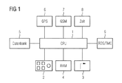
- FIG. 1 shows the components of a route planning system installed in a motor vehicle, the route planning system being designed for time-dependent route planning.
- This route planning system is integrated in an unillustrated navigation system for the subsequent navigation of the driver along the calculated route.
- the central element of the route planning system is the arithmetic unit 1, to which all other components are connected, namely an input unit 2, a display unit 3, a database stored in a first, non-volatile memory 5, a second volatile memory 4, position-determining means 6, a module for establishing a wireless communication link 7, a module for determining the current time 8 and a module for receiving traffic information 9.
- the modules for setting up a wireless communication link 7, for determining the current time 8 and for receiving traffic information 9 are optional because the information obtained about it could also be obtained by other means, for example by user input.
- the superior navigation system has in addition to the elements belonging to the route planning system further means for more accurate determination of the current position, such as a yaw rate sensor and interfaces to Radcardsensoren. Insofar as a more exact positional determination than the pure GPS position measurement by means of module 6 is not possible, the pure GPS information is sufficient for the purposes of dynamic route planning, since an approximate knowledge is required for planning a new, dynamic route depending on the current location of the user this location is sufficient.
- the first memory 5 of the route planning system contains a road network which is divided into nodes L i and edges M j , wherein each M j is assigned an anticipated travel time F j .
- each M j is assigned an anticipated travel time F j .
- the edges M j are assigned the travel time F j in the form of a historical time profile of the mean velocity or the actual travel time F jT of these edges, these edges M j either to the group of streets with the highest category, ie highways and expressways, or belonging to the group of main and through roads in agglomerations.
- the storage of the historical time profiles for all edges M j is also conceivable.
- the arithmetic unit 1 can perform a dynamic, time-dependent route planning.
- FIG. 2 shows a historical time profile of the average speed, which was determined by measurements in the course of a week on a section of a freeway near Antwerp. One sees the clear differences during the course of a day and in comparison between the working days and the days at the weekend.
- the average speed has two significant drops in speed every week, such as on Monday the speed drops 10 and 11, at times of rush hour occur in the morning (10) and in the afternoon (11). If the time profile from FIG.
- the arithmetic unit 1 would convert the average speed of approximately 80 km / h read out of the memory 5 into a probable travel time for a given time, for example Monday, 10:24 am, by it divides the length of the belonging to the distance portion near edge Antwerpen M j by the speed value.
- this conversion step is still saved in the route planning system according to FIG. 1, because instead of the average speed, the actual travel time F jT is stored as a historical time profile .
- Two profiles 12 and 13 of a measured travel time are shown in FIG. 3, both profiles having been recorded for the same edge M j , only on different but comparable days, such as on two consecutive Tuesdays. You can see the value of the measured travel time in minutes over the course of a day between 0:00 and 24:00.
- the driving time on the two days shows qualitatively a similar profile with the expected travel time extensions at the times of commuter traffic, but deviates on average from each other.
- the profile 12 shows a driving time that is about 10 minutes longer.
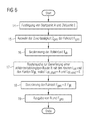
- the route planning procedure performed thereon is illustrated by the flowcharts of FIGS. 6 and 7.
- the starting point A and the destination point E of the route are determined in step 14.
- the starting point A can determine the route planning system by a GPS measurement by means 6 for position determination. However, it can also be specified differently by the user by means of the input unit 2.
- the destination E is specified by the user. Furthermore, in step 15, the user selects, for example, three possible levels-high, medium, low-the desired degree of reliability Z tot of the total travel time F tot .
- step 16 the module 8 determines from the current time and the current day as departure time T. It is also conceivable that the user specifies a deviating departure time T ab , for example, for a trip in the future.
- the central method step of route planning namely the route search performed by the arithmetic unit 1 in step 17 to generate a departure-time-dependent route R, will be explained in more detail with reference to FIG.
- the total travel time F ges calculated in step 18 from the sum of the travel times F jR of the edges M jR contained in the route R and the route R itself are output on the display unit 3 in step 19.
- the route search according to FIG. 7 results in a departure-time-dependent route R with the nodes L iR and the edges M jR , the start node L iR, start corresponding to the starting point A and the end node L iR, ending the destination E (see FIG. ,
- the route search runs as a loop, starting at the start node L iR, start (step 20). The loop continues until the node L i to be examined next corresponds to the destination point E (step 21) and so that the end of the route R is reached. From the departure time T ab and the traveled between the start node L iR, start and the node to be examined L i , previous travel time is in step 22 by summation the arrival time T an, i calculated at the node L i . The outgoing from the node to be examined L i edges M j are determined in step 23 and examined which of these edges M j contributes with its cost criterion K j least to the cost criterion K ges of the route R.
- step 24 from the historical time profiles stored in the first memory 5, the values of the actual travel time F jT and the standard deviation S j associated with the time T an, i are obtained, the actual travel time F jT being considered as the estimated travel time F j .
- the F j and S j belonging to the time T an, i, or also the sections of the historical time profiles which belong to a time including T , i can be received by an external server via the GSM module 7 via an external remote server and stored directly in the working memory, so the second memory 4, the route planning system.
- storage space in the first memory 5 can be saved since the historical time profiles are all stored in an external memory.
- the external server can, for example, be located in a traffic control center from which the time profiles measured by FCD vehicles (floating car data) or stationary sensors on the routes are evaluated, stored in the external memory as historical time profiles, and on request the route planning system are transmitted.
- the cost K j is then calculated in step 25 by increasing the expected travel time F j of each edge M j by the product of standard deviation S j and the desired degree of reliability Z ges .
- the edges M j with the broader dispersion of measured travel times thus receive higher costs K j and are therefore less likely to enter route R.
- the weighting of the standard deviation S j with the desired reliability Z ges increases the influence of a wider spread even more, so that the edges M j with the least reliability are the least represented in the route R. which increases the certainty that the travel time required by the user for the route R does not exceed the value of the total time F ges predicted by the route planning.
- the edge M jR for which the sum of the costs K j is minimal, is searched for in step 26 from the edges M j departing from the node L i , the sum being over all the edges previously assigned to the route R and via each one of L i outgoing edges M j is running. At this point, it is also sufficient to find the edge M jR with the least own cost component K jR , since only for this edge also the sum over all previous edges becomes minimal. The found edge M jR is added to the previously found route R.
- this node represents the starting node of M jR .
- the node located at the other end of the edge M jR thus forms the end node, starting the route search from this end node (step 27).
- FIG. 5 shows the result for two route planning between a starting point A and a destination point E with a different desired degree of reliability Z tot .
- the route 29 was found for a low degree of reliability Z ges and the route 28 for a higher degree.
- Route 28 tends to have lesser-category roads than rural and secondary roads, while Route 29 has highways. This is due to the fact that in this area of the route network, the highways have larger standard deviations and thus a wider dispersion of the estimated travel times than the sibling roads.
Landscapes
- Engineering & Computer Science (AREA)
- Radar, Positioning & Navigation (AREA)
- Remote Sensing (AREA)
- Physics & Mathematics (AREA)
- General Physics & Mathematics (AREA)
- Automation & Control Theory (AREA)
- Mathematical Physics (AREA)
- Health & Medical Sciences (AREA)
- General Health & Medical Sciences (AREA)
- Social Psychology (AREA)
- Navigation (AREA)
- Traffic Control Systems (AREA)
Abstract
Description
Die Erfindung betrifft ein Verfahren zur dynamischen Routenplanung in einem Routenplanungssystem, bei dem innerhalb eines, in einzelne Kanten und Knoten unterteilten, Straßennetzes eine Route zwischen einem Startpunkt und einem Zielpunkt berechnet wird, wobei die Route in Abhängigkeit von, den Kanten zugeordneten, Kanteneigenschaften bestimmt wird. Des Weiteren betrifft die Erfindung ein Routenplanungssystem zur dynamischen Routenplanung mit einer Recheneinheit, die mit einer Eingabeeinheit, einer Anzeigeeinheit und einem ersten Speicher, der ein in einzelne Kanten und Knoten unterteiltes Straßennetz enthält, verbunden ist, wobei die Recheneinheit zur Berechnung einer Route innerhalb des Straßennetzes zwischen einem Startpunkt und einem Zielpunkt, in Abhängigkeit von, den Kanten zugeordneten, Kanteneigenschaften ausgelegt ist.The invention relates to a method for dynamic route planning in a route planning system in which a route between a starting point and a destination point is calculated within a road network divided into individual edges and nodes, the route being determined as a function of edge properties associated with the edges , Furthermore, the invention relates to a route planning system for dynamic route planning with a computing unit, which is connected to an input unit, a display unit and a first memory, which contains a divided into individual edges and nodes road network, the computing unit for calculating a route within the road network between a starting point and a destination point, in dependence on the edge properties assigned to the edges.
Routenplanungssysteme mit statischer Routenplanung sind insbesondere von fest in Kraftfahrzeugen eingebauten Navigationsgeräten her bekannt. Aber auch tragbare Handgeräte, wie PDA's oder die um ein Positionserfassungsmodul erweiterten Mobilfunkgeräte, sind heutzutage in der Lage, eine statische Routenplanung und eine anschließende Navigation eines Benutzers entlang dieser Route durchzuführen. Daneben gibt es noch die reinen Routenplanungssysteme, mit denen ausschließlich eine statische Route geplant, jedoch keine Navigation durchgeführt werden kann.
Unter statischer Routenplanung versteht man dabei die Bestimmung einer Route in einem Straßennetz zwischen einem Start- und einem Zielpunkt, wobei das Straßennetz statisch, d.h. zeitlich unveränderlich, ist. Für die Routenplanung ist das in einem Speicher des Routenplanungssystems abgelegte Straßennetz in Kanten und Knoten unterteilt, wobei den Kanten jeweils eigene Kanteneigenschaften zugeordnet werden, die als Routenplanungskosten verstanden werden. Der Routenplanungsalgorithmus sucht nun nach der Route zwischen dem Start- und dem Zielpunkt, die ein bestimmtes Kostenkriterium optimiert bzw. minimiert. Solche Kostenkriterien können beispielsweise sein die Länge der Gesamtroute, das Befahren möglichst weniger Autobahnen, das schnellstmögliche Erreichen des Zielpunktes etc. Als Kanteneigenschaften werden entsprechend zugeordnet die Länge der Kante, die mittlere Geschwindigkeit für diese Kante oder der Straßentyp der Kante.Route planning systems with static route planning are known, in particular, from navigation devices permanently installed in motor vehicles. However, handheld portable devices such as PDAs or mobile radio devices extended by a position detection module are also able to carry out static route planning and subsequent navigation of a user along this route. In addition, there are the pure route planning systems with which only a static route planned, but no navigation can be performed.
Static route planning is understood as the determination of a route in a road network between a start and a destination point, the road network static, ie fixed in time, is. For route planning, the road network stored in a memory of the route planning system is subdivided into edges and nodes, wherein the edges are each assigned their own edge properties, which are understood as route planning costs. The route planning algorithm now searches for the route between the start and the destination point, which optimizes or minimizes a certain cost criterion. Such cost criteria can be, for example, the length of the entire route, driving on as few freeways as possible, the fastest possible reaching of the destination point, etc. The edge properties are correspondingly assigned to the length of the edge, the average speed for this edge or the road type of the edge.
Eine bekannte Erweiterung der herkömmlichen Funktionalität stellt die dynamische Routenplanung unter Berücksichtigung von aktuellen Verkehrsinformationen dar. Die per Funk empfangenen Verkehrsinformationen werden hinsichtlich ihrer Relevanz für die vorab statisch geplante Route ausgewertet. Erhöht sich infolge einer Verkehrsbehinderung die für das Zurücklegen der statischen Route benötigte Fahrzeit, so wird eine dynamische Route geplant und dem Benutzer entweder zur Auswahl angeboten oder als neue Route einer folgenden Navigation zugrunde gelegt. Bei der dynamischen Routenplanung werden die den betroffenen Straßennetz-Kanten zugeordneten Kanteneigenschaften entsprechend der Verkehrsinformation verändert, d.h. dass beispielsweise die mittlere Geschwindigkeit herabgesetzt wird. Dadurch erhöhen sich entsprechend die Routenplanungskosten für diese Kante. Allgemein gilt also für das bisherige Verständnis des Begriffs dynamische Routenplanung, dass nach der Berechnung einer ersten, nämlich der statischen, Route im Fall von Änderungen der Kanteneigenschaften eine zweite Route berechnet wird.A known extension of the conventional functionality is the dynamic route planning taking into account current traffic information. The traffic information received by radio is evaluated with regard to its relevance to the previously statically planned route. If, as a result of a traffic obstruction, the travel time required to cover the static route increases, a dynamic route is planned and either offered to the user for selection or as a new route for subsequent navigation. In dynamic route planning, the edge properties associated with the road network edges concerned are changed in accordance with the traffic information, ie, for example, the average speed is reduced. This increases accordingly the route planning costs for this edge. In general, therefore, for the current understanding of the term dynamic route planning, it holds that after the calculation of a first, namely the static, route in the case of changes in the edge properties, a second route is calculated.
Da die Verkehrsinformationen im allgemeinen nur die geographische Länge von Staus oder die Position von Behinderungsstellen angeben, nicht jedoch die zu erwartende Fahrzeitverlängerung, muss die Fahrzeitverlängerung im allgemeinen vom Routenplanungssystem ermittelt werden, wobei dies nur durch eine grobe Schätzung möglich ist, da eine Staulänge noch nichts über eine mittlere Geschwindigkeit in diesem Stau aussagt. Alternativ schlägt die DE-10219500-A1 vor, dem Benutzer die Staulänge anzuzeigen und von ihm die Fahrzeitverlängerung aufgrund seiner Erfahrung abschätzen zu lassen. In für den Benutzer unbekannten Verkehrsgebieten wird dies jedoch nicht so leicht möglich sein. Außerdem erfordert diese Ausführung eine Interaktion zwischen dem Benutzer und dem Routenplanungssystem während der Fahrt, was unter Umständen als störend oder ablenkend empfunden werden kann. Allgemein nachteilig bei der dynamischen Routenplanung auf Basis von per Verkehrsfunk übertragenen Informationen ist des Weiteren, dass die Informationen nur binäre Inhalte haben, also "Stau vorhanden/nicht vorhanden". Daraus resultiert eine sprunghafte Änderung der von der Routenplanung vorhergesagten Fahrzeit.Since the traffic information generally only indicates the geographical length of traffic jams or the position of disability points, but not the expected travel time extension, the travel time extension generally has to be determined by the route planning system, which is only possible by a rough estimate, since a traffic jam is still nothing says about a mean speed in this jam. Alternatively, DE-10219500-A1 proposes to indicate to the user the stowage length and to let him estimate the travel time extension based on his experience. In traffic areas unknown to the user, however, this will not be so easily possible. In addition, this embodiment requires interaction between the user and the route planning system while driving, which may be distracting or distracting. Another disadvantage of the dynamic route planning based on information transmitted by traffic information is that the information has only binary content, ie "jam present / not available". This results in a sudden change in the travel time predicted by the route planning.
Aufgabe der vorliegenden Erfindung ist es, ein Verfahren und ein Routenplanungssystem der eingangs genannten Art anzugeben, die die genannten Probleme der dynamischen Routenplanung lösen.Object of the present invention is to provide a method and a route planning system of the type mentioned, which solve the problems of dynamic route planning mentioned.
Diese Aufgabe wird mit einem Verfahren nach Anspruch 1 und einem Routenplanungssystem nach Anspruch 18 gelöst.This object is achieved by a method according to
Bei dem erfindungsgemäßen Verfahren wird mindestens einer Kante des Straßennetzes als Kanteneigenschaft eine voraussichtliche Fahrzeit zugeordnet, wobei die voraussichtliche Fahrzeit von einem vorgegeben Zeitpunkt abhängig ist. Eine solche zeitpunktabhängige Fahrzeit ermöglicht eine zeitpunktabhängige Routenplanung. Eine zeitpunktabhängige Routenplanung ist wiederum nichts anderes als eine dynamische Routenplanung, da hierbei die zeitlich veränderlichen Verkehrsbedingungen innerhalb des Straßennetzes berücksichtigt werden. Insbesondere aus Ballungsgebieten ist ja die Tatsache bekannt, dass beispielsweise im Laufe eines Tages die Verkehrsbelastung bestimmter Streckenabschnitte deutlichen Schwankungen unterworfen ist. Je nachdem zu welchem Zeitpunkt ein Benutzer bestimmte Streckenabschnitte passiert, benötigt er dafür eine kürzere oder längere Fahrzeit. Indem mindestens einer Kante eine vom Zeitpunkt abhängige voraussichtliche Fahrzeit zugeordnet wird, kann die Routenplanung für Routen entlang dieser mindestens einen Kante unterschiedliche benötigte gesamte Fahrzeiten vorhersagen, beispielsweise in Abhängigkeit von der Tages- oder Uhrzeit. Die gesamten Fahrzeiten ergeben sich dabei aus der Summe aus der bzw. den zeitpunktabhängigen Fahrzeiten und der statischen Fahrzeit für die übrigen Kanten der Route, wobei die statische Fahrzeit mit den üblichen Verfahren, also beispielsweise aus der Summe der Kantenlängen und der mittleren Geschwindigkeit, bestimmt wird. Bei dem erfindungsgemäßen Verfahren wird die bisher grobe Abschätzung von Fahrzeitänderungen aufgrund von Verkehrsinformationen durch genaue Daten ersetzt. Eine zusätzliche Interaktion mit dem Benutzer ist nicht mehr erforderlich und die vorhergesagte Fahrzeit ändert sich graduell mit dem vorgegebenen Zeitpunkt und nicht mehr in großen Sprüngen. Ein allmähliches Auf- und Abbauen von Staus wird also direkt berücksichtigt.In the method according to the invention, at least one edge of the road network is assigned an estimated driving time as an edge property, the estimated one Travel time depends on a given time. Such time-dependent travel time allows a time-dependent route planning. A time-dependent route planning is in turn nothing more than a dynamic route planning, since in this case the time-varying traffic conditions within the road network are taken into account. In particular, from agglomerations yes, the fact is known, for example, in the course of a day, the traffic load of certain sections is subject to significant fluctuations. Depending on when a user passes certain sections of the route, he needs a shorter or longer travel time. By allocating at least one edge to a time-dependent prospective travel time, the route planning for routes along this at least one edge can predict different total travel times required, for example, depending on the time of day or time. The total travel times result from the sum of the time or the time-dependent travel times and the static travel time for the other edges of the route, the static travel time with the usual methods, so for example from the sum of the edge lengths and the average speed is determined , In the method according to the invention, the previously rough estimate of travel time changes due to traffic information is replaced by accurate data. An additional interaction with the user is no longer required and the predicted driving time changes gradually with the given time and no longer in large jumps. A gradual construction and dismantling of traffic jams is therefore taken directly into account.
Bei dem erfindungsgemäßen Routenplanungssystem ist die voraussichtliche, von einem vorgegebenen Zeitpunkt abhängige Fahrzeit zu der mindestens einen Kante des Straßennetzes in dem ersten oder einem zweiten Speicher abgelegt. Je nachdem, auf welchem Wege die voraussichtliche Fahrzeit dem Routenplanungssystem zur Verfügung gestellt wird, ob auf einem Festwertspeicher oder per Datenfernübertragung, ist diese Information in dem Festwertspeicher oder einem Arbeitsspeicher des Routenplanungssystems enthalten.In the route planning system according to the invention, the probable travel time, which is dependent on a predefined time, is stored in the first or in a second memory at the at least one edge of the road network. Depending on how the estimated travel time is made available to the route planning system, whether on a read-only memory or by remote data transmission, this information is contained in the read-only memory or a working memory of the route planning system.
Bevorzugt ist die mindestens eine Kante eine von zyklischen Verkehrsbehinderungen betroffene Kante. Es wird also eine Kante gewählt, die besonders starken Schwankungen in der voraussichtlichen Fahrzeit unterworfen ist, da eine solche Kante die für die gesamte Route benötigte Fahrzeit, im Folgenden Gesamtfahrzeit genannt, am stärksten beeinflusst. Je mehr solcher Kanten mit einer zeitpunktabhängigen, voraussichtlichen Fahrzeit versehen werden, um so genauer wird die Vorhersagt der Gesamtfahrzeit durch die Routenplanung.The at least one edge is preferably an edge affected by cyclical traffic obstructions. Thus, an edge is selected which is subject to particularly strong fluctuations in the anticipated travel time, since such an edge has the greatest effect on the travel time required for the entire route, referred to below as the total travel time. The more such edges are provided with a time-dependent, probable travel time, the more accurate is the prediction of the total travel time by the route planning.
Der vorgegebene Zeitpunkt, von dem die voraussichtliche Fahrzeit abhängt, ist bevorzugt die Tageszeit und/oder der Wochentag. Dabei kann es aus Speicherplatzgründen sinnvoll sein, je nachdem, ob die Verkehrsbehinderungen nur über den Tag verteilt, nur über eine Woche verteilt oder an jedem Tag in der Woche stark schwanken, entsprechend nur die Tageszeit, nur den Wochentag oder beide Größen der voraussichtlichen Fahrzeit zuzuordnen. Weiterhin ist für Regionen, in denen starke saisonale Unterschiede zu verzeichnen sind, beispielsweise Tourismusgebieten, auch die Angabe des Monats als Zeitpunkt denkbar.The predetermined time, on which the estimated travel time depends, is preferably the time of day and / or the day of the week. It may be useful for space reasons, depending on whether the traffic delays distributed only over the day, distributed only over a week or fluctuate sharply every day of the week, according to only assign the time of day, only the day of the week or both sizes of the estimated travel time , Furthermore, for regions where there are strong seasonal differences, such as tourism areas, the month as a date is also conceivable.
In einer weiteren bevorzugten Ausführung der Erfindung wird der vorgegebene Zeitpunkt als der Zeitpunkt bestimmt, zu dem der Benutzer des Routenplanungssystems die mindestens eine Kante voraussichtlich erreichen wird. Entweder gibt der Benutzer diesen Zeitpunkt direkt vor oder er wird vom Routenplanungssystem ausgehend vom Abfahrtszeitpunkt und dem Abfahrtsort des Benutzers berechnet. Auf diese Weise kann also eine abfahrtzeitabhängige Routenplanung durchgeführt werden, mit deren Hilfe ein Benutzer beispielsweise im Vorfeld klären kann, zu welcher Tageszeit die voraussichtlich schnellste Fahrt möglich ist. Für Geschäftsreisende bietet dies beispielsweise die Möglichkeit, die Termine eines Tages an die voraussichtliche Verkehrssituation anzupassen, um so wenig Zeit wie möglich im Fahrzeug und so viel wie möglich bei den Kunden zu verbringen.In a further preferred embodiment of the invention, the predetermined time is determined as the time at which the user of the route planning system is likely to reach the at least one edge. Either the user specifies this time directly or is calculated by the route planning system based on the time of departure and the place of departure of the user. In this way, therefore, a departure-time-dependent route planning can be performed, with the help of which a user clarify, for example, in advance can at what time of day the expected fastest ride is possible. For business travelers, for example, this offers the possibility to adjust the appointments of one day to the anticipated traffic situation in order to spend as little time as possible in the vehicle and as much as possible with the customers.
Befindet sich in einem speziellen Fall der Benutzer bereits mitten auf seiner Route und muss die Route umgeplant werden, so kann das zu einem Navigationssystem gehörende Routenplanungssystem ausgehend von der aktuell gemessenen Zeit und dem aktuellen Standort des Benutzers auf den voraussichtlichen Zeitpunkt des Erreichens der mindestens einen Kante schließen.In a special case, if the user is already in the middle of his route and the route has to be rescheduled, the navigation system belonging to a navigation system can start from the currently measured time and the current location of the user at the presumable time of reaching the at least one edge shut down.
In einer Ausgestaltung der Erfindung wird die voraussichtliche Fahrzeit für die mindestens eine Kante aus einem historischen Zeitprofil der mittleren Geschwindigkeit dieser Kante gewonnen und in einer anderen Ausgestaltung aus dem historischen Zeitprofil der tatsächlichen Fahrzeit dieser Kante. Solche Zeitprofile werden durch einfache Messungen dadurch gewonnen, dass die jeweilige Größe über einen bestimmten Zeitraum, beispielsweise den Verlauf eines Tages, einer Woche oder eines Monats, aufgezeichnet wird. Bei einem solchen Zeitprofil ist also eine direkte, beispielsweise tabellarische, Zuordnung zwischen einem festen Zeitpunkt und der gemessenen Größe möglich. Aus der zugeordneten tatsächlichen Fahrzeit bzw. der mittleren Geschwindigkeit und der Kantenlänge kann dann auf einfache Weise die voraussichtliche Fahrzeit zu dem jeweiligen Zeitpunkt ermittelt werden.In one embodiment of the invention, the probable travel time for the at least one edge is obtained from a historical time profile of the average speed of this edge, and in another embodiment from the historical time profile of the actual travel time of this edge. Such time profiles are obtained by simple measurements by recording the respective variable over a certain period of time, for example the course of a day, a week or a month. With such a time profile, therefore, a direct, for example tabular, association between a fixed point in time and the measured size is possible. From the assigned actual travel time or the average speed and the edge length can then be determined in a simple manner, the estimated travel time at the respective time.
Bei einer speziellen Ausgestaltung der Erfindung wird die voraussichtliche Fahrzeit für die mindestens eine Kante mit einem Zuverlässigkeitswert versehen. Dieser Zuverlässigkeitswert stellt ebenfalls eine Kanteneigenschaft dar und ermöglicht eine Bewertung der von der Routenplanung errechneten Gesamtfahrzeit. Je höher dieser Wert ist desto mehr kann sich der Benutzer darauf verlassen, dass seine benötigte Fahrzeit für die betroffene Kante die voraussichtliche Fahrzeit nicht überschreiten wird. Je mehr Kanten der Route mit einer zeitpunktabhängigen Fahrzeit und einem solchen Zuverlässigkeitswert versehen sind, desto verlässlicher ist dann auch der Wert der vorhergesagten Gesamtzeit.In a specific embodiment of the invention, the estimated travel time for the at least one edge provide a reliability value. This reliability value also represents an edge property and allows an evaluation of the total travel time calculated by the route planning. The higher this value is, the more the user can be sure that his required travel time for the affected edge will not exceed the anticipated travel time. The more edges of the route are provided with a time-dependent driving time and such a reliability value, the more reliable is the value of the predicted total time.
Der Zuverlässigkeitswert wird gemäß einer besonderen Ausführung aus einem historischen Zeitprofil der Standardabweichung der tatsächlichen Fahrzeit bzw. der Standardabweichung der mittleren Geschwindigkeit der mindestens einen Kante gewonnen. Um ein solches Zeitprofil zu generieren, werden tatsächliche Fahrzeit oder die mittlere Geschwindigkeit nicht nur über einen bestimmten Zeitraum sondern über mehrere gleiche Zeiträume, beispielsweise mehrere aufeinander folgende Montage, aufgezeichnet. Daraus resultieren mehrere, vergleichbare Zeitprofile der jeweiligen Größe, deren Standardabweichung berechnet werden kann. Eine hohe Standardabweichung bedeutet dabei einen geringen Wert an Zuverlässigkeit, d.h. ein zugeordneter Zuverlässigkeitswert könnte beispielsweise aus der Inversen der Standardabweichung gewonnen werden.The reliability value is obtained according to a particular embodiment from a historical time profile of the standard deviation of the actual travel time or the standard deviation of the average speed of the at least one edge. In order to generate such a time profile, the actual travel time or the average speed is recorded not only over a certain period of time but over several equal time periods, for example several successive montages. This results in several comparable time profiles of the respective size whose standard deviation can be calculated. A high standard deviation means a low value of reliability, i. For example, an associated reliability value could be obtained from the inverse of the standard deviation.
Anstelle der zeitpunktabhängigen Fahrzeit oder auch zusätzlich zu dieser Größe kann zu der mindestens einen Kante eine weitere, die Routenplanungskosten für diese Kante repräsentierende, Größe generiert werden. Dies hängt von dem verwendeten Routenplanungsalgorithmus und dem zu optimierenden Kostenkriterium ab. Wird beispielsweise nach einer Route gesucht, deren gesamte mittlere Geschwindigkeit einen höchstmöglichen Wert erreichen soll, so kann die zeitpunktabhängige Fahrzeit unter Hinzuziehung der Kantenlänge in eine zeitpunktabhängige mittlere Geschwindigkeit umgerechnet werden. Ein anderes Beispiel sind auf eine dimensionslose Größe normierte Kosten, in deren Berechnung die zeitpunktabhängige Fahrzeit einbezogen wird.Instead of the time-dependent travel time or in addition to this size, a further size representing the route planning costs for this edge can be generated for the at least one edge. This depends on the route planning algorithm used and the cost criterion to be optimized. For example, if you are looking for a route whose overall average speed is the highest possible Value is to reach, then the time-dependent driving time can be converted by using the edge length in a time-dependent average speed. Another example is a normalized to a dimensionless size costs, in the calculation of the time-dependent driving time is included.
Wird der mindestens einen Kante ein Zuverlässigkeitswert zugeordnet, so kann in einer besonders vorteilhaften Ausgestaltung der Erfindung der Benutzer einen gewünschten Grad an Zuverlässigkeit der Gesamtfahrzeit vorgeben, welcher während der Routenplanung berücksichtigt wird. Die durch Messungen oder statistische Untersuchungen gewonnenen, zeitpunktabhängigen voraussichtlichen Fahrzeiten bilden zwar das Verkehrsgeschehen für die mindestens eine Kante im Mittel sehr gut ab, können jedoch in ihren Einzelwerten beliebig weit streuen. Durch die Einbeziehung von Zuverlässigkeitswerten kann dem Benutzer ein Gefühl für die Verlässlichkeit der vorhergesagten Gesamtfahrzeit vermittelt werden. Ist es ihm besonders wichtig, dass die vorhergesagte Gesamtfahrzeit nicht überschritten wird, so wählt er einen hohen gewünschten Grad an Zuverlässigkeit.If the at least one edge is assigned a reliability value, then, in a particularly advantageous embodiment of the invention, the user can specify a desired degree of reliability of the total travel time, which is taken into account during the route planning. The time-dependent estimated driving times obtained by measurements or statistical investigations, although the traffic situation for the at least one edge on average very well, but can scatter in their individual values arbitrarily far. By including reliability values, the user can be given a sense of the reliability of the predicted total travel time. If it is particularly important to him that the predicted total travel time is not exceeded, he chooses a high desired degree of reliability.
Damit die Berücksichtigung des gewünschten Grades an Zuverlässigkeit mit möglichst geringem Aufwand in einen bestehenden Routenplanungsalgorithmus eingebunden werden kann, wird in einer speziellen Ausführung ein erstes, von der Routenplanung zu optimierendes Kostenkriterium an den gewünschten Grad an Zuverlässigkeit angepasst. Bevorzugt wird dabei ein auch bei statischen Routenplanungsalgorithmen verwendetes Kostenkriterium eingesetzt, nämlich die Minimierung der Summe der voraussichtlichen Fahrzeiten aller eine Route bildenden Kanten. Die voraussichtlichen Fahrzeiten sind dabei entweder zeitpunktabhängige oder statische Fahrzeiten.So that the consideration of the desired degree of reliability can be integrated into an existing route planning algorithm with the least possible effort, in a specific embodiment a first cost criterion to be optimized by the route planning is adapted to the desired degree of reliability. Preferably, a cost criterion also used in static route planning algorithms is used, namely the minimization of the sum of the anticipated travel times of all edges forming a route. The estimated travel times are either time-dependent or static travel times.
Die Anpassung dieses ersten Kostenkriteriums an den gewünschten Grad an Zuverlässigkeit erfolgt bevorzugt durch eine Erhöhung der Routenplanungskosten in Abhängigkeit von dem der mindestens einen Kante zugeordneten Zuverlässigkeitswert. Dafür wird die der Kante zugeordnete, zeitpunktabhängige voraussichtliche Fahrzeit um einen Unsicherheitsbetrag erhöht, welcher mit steigendem Zuverlässigkeitswert sinkt. Für den Spezialfall der Verwendung der sich zur Zuverlässigkeit entgegengesetzt verhaltenden Standardabweichung muss der Unsicherheitsbetrag mit steigender Standardabweichung demnach steigen. Als Ergebnis weisen die Kanten mit der geringsten Zuverlässigkeit und damit der breitesten Streuung der voraussichtlichen Fahrzeit die höchsten Routenplanungskosten auf und werden bei einem hohen gewünschten Grad an Zuverlässigkeit der Gesamtfahrzeit wahrscheinlich nicht mehr Bestandteil der Route sein.The adaptation of this first cost criterion to the desired degree of reliability preferably takes place by increasing the route planning costs as a function of the reliability value assigned to the at least one edge. For this purpose, the edge-related, time-dependent anticipated travel time is increased by an amount of uncertainty which decreases with increasing reliability value. For the special case of using the standard deviation behaving contrary to the reliability, the uncertainty amount must increase with increasing standard deviation accordingly. As a result, the edges with the least reliability, and thus the widest dispersion of the estimated travel time, have the highest route planning costs and, with a high desired degree of reliability of the total travel time, will probably no longer be part of the route.
In einer weiteren Ausgestaltung der Erfindung wird neben dem ersten ein zweites zu optimierendes Kostenkriterium eingeführt und das erste und das zweite Kostenkriterium wird je nach gewünschtem Grad an Zuverlässigkeit unterschiedlich gewichtet. Die gewichteten Kostenkriterien werden dann zu einem übergeordneten Kostenwert zusammengefasst, so dass bei der Routenplanung nach einer Route gesucht wird, die den übergeordneten Kostenwert optimiert. Anstelle der Erhöhung der voraussichtlichen Fahrzeit um einen Unsicherheitsbetrag, was einer Abänderung eines ersten Kostenkriteriums entspricht, wird in dieser Ausgestaltung das erste, auch bei statischen Routenplanungen verwendete, Kostenkriterium unverändert beibehalten und über das zweite Kostenkriterium wird zusätzlich der gewünschte Grad an Zuverlässigkeit berücksichtigt. Gibt der Benutzer keinen gewünschten Grad vor, so wird das zweite Kostenkriterium einfach mit Null gewichtet und der Routenplanungsalgorithmus läuft auf herkömmliche Art und Weise ab.In a further embodiment of the invention, a second cost criterion to be optimized is introduced in addition to the first, and the first and the second cost criterion are weighted differently depending on the desired degree of reliability. The weighted cost criteria are then summarized to a higher cost value, so that the route planning is searched for a route that optimizes the parent cost. Instead of increasing the probable travel time by an uncertainty amount, which corresponds to a modification of a first cost criterion, the first cost criterion used in static route planning is maintained unchanged in this refinement and the second cost criterion is additionally used the desired degree of reliability is taken into account. If the user does not specify a desired degree, then the second cost criterion is simply weighted zero and the route planning algorithm runs in a conventional manner.
Als zweites Kostenkriterium wird in einer besonderen Ausführung die Summe der Zuverlässigkeitswerte aller eine Route bildenden Kanten minimiert. Eine Wichtung des ersten und zweiten Kostenkriteriums erfolgt dabei bevorzugt so, dass mit zunehmendem gewünschten Grad an Zuverlässigkeit das erste Kostenkriterium niedriger und das zweite Kostenkriterium höher gewichtet wird. Bezogen auf die besondere Ausführung bedeutet dies, dass mit höherer gewünschter Zuverlässigkeit die Summe der Zuverlässigkeitswerte aller Kanten stärker in den übergeordneten Kostenwert eingeht und die Summe der Fahrzeiten aller Kanten weniger stark. Auf diese Weise wird ein Kompromiss gefunden zwischen dem Wunsch nach möglichst geringer Gesamtfahrzeit und dem Wunsch nach möglichst hoher Zuverlässigkeit, da die Route mit der höchsten Zuverlässigkeit unter Umständen eine der langsamsten Routen sein kann.As a second cost criterion, the sum of the reliability values of all edges forming a route is minimized in a particular embodiment. A weighting of the first and second cost criterion is preferably carried out so that with increasing the desired degree of reliability, the first cost criterion is weighted lower and the second cost criterion higher. In relation to the particular embodiment, this means that with higher desired reliability, the sum of the reliability values of all edges is more strongly included in the superordinate cost value, and the sum of the travel times of all edges less pronounced. In this way, a compromise is found between the desire for the lowest overall travel time and the desire for the highest possible reliability, since the route with the highest reliability may be one of the slowest routes.
Bei einer besonderen Ausgestaltung des erfindungsgemäßen Routenplanungssystems ist ein Modul zur Bestimmung der aktuellen Zeit mit der Recheneinheit verbunden. Mit dieser Ausgestaltung kann das Routenplanungssystem entweder die Abfahrtzeit des Benutzers oder im Fall, dass der Benutzer sich bereits auf der Route befindet, die aktuelle Zeit in Verbindung mit einem aktuellen Standort bestimmen. In beiden Fällen ist dann die Recheneinheit des Routenplanungssystems in der Lage den Zeitpunkt zu bestimmen, zu dem der Benutzer voraussichtlich die mindestens eine Kante erreichen wird.In a particular embodiment of the route planning system according to the invention, a module for determining the current time is connected to the arithmetic unit. With this configuration, the route planning system can determine either the departure time of the user or, in the case that the user is already on the route, the current time in connection with a current location. In both cases, the computing unit of the route planning system is then able to determine the point in time at which the user is expected to reach the at least one edge.
In einer weiteren Ausgestaltung ist die Eingabeeinheit des Routenplanungssystems so ausgelegt, dass der Benutzer einen gewünschten Grad an Zuverlässigkeit der Gesamtfahrzeit vorgeben oder auswählen kann. Eine direkte Vor- bzw. Eingabe könnte per Tastatur oder Spracherkennung erfolgen und eine Auswahl per Scroll- oder Cursorfunktion in Verbindung mit einer Enterfunktion.In a further embodiment, the input unit of the route planning system is designed so that the user can specify or select a desired degree of reliability of the total travel time. A direct input or input could be made by keyboard or speech recognition and a selection by scroll or cursor function in conjunction with an enter function.
Weiterhin ist in einer Ausführung des Routenplanungssystems vorgesehen, dass ein Modul zum Empfang von Verkehrsinformationen vorhanden ist. Die Verkehrsinformationen werden jedoch nicht in jedem Fall, sondern erst ab dem Überschreiten eines vorgegebenen Schweregrades der Verkehrsbehinderung in die Routenplanung mit einbezogen. Die Schwelle des Schweregrades kann beispielsweise definiert sein als eine minimale Fahrzeitverlängerung. Da ja gemäß der Erfindung zyklisch immer wieder kehrende Verkehrsbehinderungen und die damit verbundene Fahrzeitverlängerung bereits berücksichtigt sind, werden nur noch außergewöhnliche Ereignisse, wie Vollsperrungen, Baustellen oder besonders lange Staus, an die Routenplanung weitergegeben. Diese außergewöhnlichen Ereignisse werden dann in der bekannten Weise als Verkehrsinformation bei der dynamischen Routenplanung berücksichtigt.Furthermore, it is provided in one embodiment of the route planning system that a module for receiving traffic information is present. However, the traffic information is not always included in the route planning, but only after exceeding a predetermined severity level of the traffic obstruction. The threshold of severity, for example, may be defined as a minimum travel time extension. Since, according to the invention, cyclical recurring traffic obstructions and the associated travel time extension are already taken into account, only extraordinary events, such as full closures, construction sites or particularly long traffic jams, are passed on to the route planning. These extraordinary events are then considered in the known manner as traffic information in the dynamic route planning.
Weitere Ausgestaltungen der Erfindung gehen aus den Unteransprüchen hervor.Further embodiments of the invention will become apparent from the dependent claims.
Die Erfindung wird nachfolgend anhand eines Ausführungsbeispiels und der Zeichnung näher erläutert. Es zeigen:
- Fig. 1
- ein Routenplanungssystem zur zeitpunktabhängigen Routenplanung;
- Fig. 2
- ein historisches Zeitprofil der mittleren Geschwindigkeit über einer Woche;
- Fig. 3
- zwei historische Zeitprofile der tatsächlichen Fahrzeit über einem Tag, für denselben Streckenabschnitt;
- Fig. 4
- historisches Zeitprofil der tatsächlichen Fahrzeit und der dazugehörigen Standardabweichung über einem Tag;
- Fig. 5
- Ergebnis der Routensuche für unterschiedliche vorgegebene Zuverlässigkeitswerte der Gesamtfahrzeit;
- Fig. 6
- Ablaufdiagramm einer Routenplanung mit abfahrtzeitabhängiger Routensuche;
- Fig. 7
- Ablaufdiagramm der abfahrtzeitabhängigen Routensuche.
- Fig. 1
- a route planning system for time-dependent route planning;
- Fig. 2
- a historical time profile of average speed over a week;
- Fig. 3
- two historical time profiles of the actual journey time over one day, for the same section of the route;
- Fig. 4
- historical time profile of the actual journey time and the associated standard deviation over one day;
- Fig. 5
- Result of the route search for different predefined reliability values of the total travel time;
- Fig. 6
- Flowchart of a route planning with departure-time-dependent route search;
- Fig. 7
- Flowchart of the departure-time-dependent route search.
In Figur 1 sind die Bestandteile eines in ein Kraftfahrzeug eingebauten Routenplanungssystems dargestellt, wobei das Routenplanungssystem für eine zeitpunktabhängige Routenplanung ausgelegt ist. Dieses Routenplanungssystem ist in ein nicht dargestelltes Navigationssystem integriert zur anschließenden Navigation des Fahrzeugführers entlang der berechneten Route. Zentrales Element des Routenplanungssystems ist die Recheneinheit 1, mit der alle übrigen Komponenten verbunden sind, nämlich eine Eingabeeinheit 2, eine Anzeigeeinheit 3, eine in einem ersten, nichtflüchtigen Speicher 5 abgelegte Datenbank, ein zweiter flüchtiger Speicher 4, Mittel zur Positionsbestimmung 6, ein Modul zum Aufbau einer drahtlosen Kommunikationsverbindung 7, ein Modul zur Bestimmung der aktuellen Zeit 8 und ein Modul zum Empfang von Verkehrsinformationen 9. Bei dem Routenplanungssystem sind die Module zum Aufbau einer drahtlosen Kommunikationsverbindung 7, zur Bestimmung der aktuellen Zeit 8 und zum Empfang von Verkehrsinformationen 9 optional, da die darüber ermittelten Informationen auch auf anderem Wege, beispielsweise per Benutzereingabe, erlangt werden könnten. Das übergeordnete Navigationssystem verfügt neben den zum Routenplanungssystem gehörenden Elementen noch über weitere Mittel zur genaueren Bestimmung der aktuellen Position, wie beispielsweise einen Gierratensensor und Schnittstellen zu Raddrehzahlsensoren. Sofern eine gegenüber der reinen GPS-Positionsmessung mittels Modul 6 genauere Positionsbestimmung nicht möglich ist, genügt für die Zwecke der dynamischen Routenplanung auch die reine GPS-Information, da für die Planung einer neuen, dynamischen Route in Abhängigkeit vom aktuellen Standort des Benutzers eine ungefähre Kenntnis dieses Standortes ausreicht.FIG. 1 shows the components of a route planning system installed in a motor vehicle, the route planning system being designed for time-dependent route planning. This route planning system is integrated in an unillustrated navigation system for the subsequent navigation of the driver along the calculated route. The central element of the route planning system is the
Der erste Speicher 5 des Routenplanungssystems enthält ein in Knoten Li und in Kanten Mj unterteiltes Straßennetz, wobei allen Mj jeweils eine voraussichtliche Fahrzeit Fj zugeordnet ist. Aus Speicherplatzgründen ist nur einigen Kanten Mj die Fahrzeit Fj in Form eines historischen Zeitprofils der mittleren Geschwindigkeit oder der tatsächlichen Fahrzeit FjT dieser Kanten zugeordnet, wobei diese Kanten Mj entweder zur Gruppe an Straßen mit der höchsten Kategorie, also Autobahnen und Schnellstraßen, oder zur Gruppe der Haupt- und Durchfahrtsstraßen in Ballungsgebieten gehören. Sobald zukünftige Speicher mit deutlich größerer Kapazität zu deutlich geringerem Preis erhältlich sein werden, ist auch die Abspeicherung der historischen Zeitprofile für alle Kanten Mj denkbar. Auf Basis der im ersten Speicher 5 abgelegten Daten kann die Recheneinheit 1 eine dynamische, zeitpunktabhängige Routenplanung durchführen.The
Figur 2 zeigt ein historisches Zeitprofil der mittleren Geschwindigkeit, welches im Verlauf einer Woche auf einem Streckenabschnitt einer Schnellstraße nahe Antwerpen durch Messungen ermittelt wurde. Man sieht die deutlichen Unterschiede im Verlauf eines Tages und im Vergleich zwischen den Arbeitstagen und den Tagen am Wochenende. Die mittlere Geschwindigkeit weist wochentäglich zwei deutliche Geschwindigkeitseinbrüche auf, so beispielsweise am Montag die Geschwindigkeitseinbrüche 10 und 11, die zu Zeiten des Berufsverkehrs am Vormittag (10) und am Nachmittag (11) auftreten. Sofern das Zeitprofil aus Figur 2 im Speicher 5 abgelegt ist, würde die Recheneinheit 1 die für einen vorgegebenen Zeitpunkt, beispielsweise Montag, 10:24 Uhr, aus dem Speicher 5 ausgelesene mittlere Geschwindigkeit von rund 80 km/h in eine voraussichtliche Fahrzeit umrechnen, indem sie die Länge der zu dem Streckenabschnitt nahe Antwerpen gehörenden Kante Mj durch den Geschwindigkeitswert dividiert.FIG. 2 shows a historical time profile of the average speed, which was determined by measurements in the course of a week on a section of a freeway near Antwerp. One sees the clear differences during the course of a day and in comparison between the working days and the days at the weekend. The average speed has two significant drops in speed every week, such as on Monday the speed drops 10 and 11, at times of rush hour occur in the morning (10) and in the afternoon (11). If the time profile from FIG. 2 is stored in the
Dieser Umwandlungsschritt wird in dem Routenplanungssystem nach Figur 1 jedoch noch eingespart, da anstelle der mittleren Geschwindigkeit die tatsächliche Fahrzeit FjT als historisches Zeitprofil gespeichert wird. Zwei Profile 12 und 13 einer gemessenen Fahrzeit sind in Figur 3 abgebildet, wobei beide Profile für dieselbe Kante Mj, nur an unterschiedlichen, aber miteinander vergleichbaren Tagen, wie beispielsweise an zwei aufeinander folgenden Dienstagen, aufgenommen wurden. Zu sehen ist der Wert der gemessenen, Fahrzeit in Minuten über dem Verlauf eines Tages zwischen 0:00 Uhr und 24:00 Uhr. Die Fahrzeit weist zwar an den beiden Tagen qualitativ ein vergleichbares Profil auf mit den zu erwartenden Fahrzeitverlängerungen zu den Zeiten des Berufsverkehrs, jedoch weicht sie im Mittel voneinander ab. Das Profil 12 zeigt eine um rund 10 Minuten längere Fahrzeit.However, this conversion step is still saved in the route planning system according to FIG. 1, because instead of the average speed, the actual travel time F jT is stored as a historical time profile . Two
Aus mehreren solcher für denselben Wochentag aufgenommenen Fahrzeit-Profile wird vorab ein Mittelwert gebildet, woraus die so genannte tatsächlichen Fahrzeit FjT resultiert. Des Weiteren werden für die mehreren gemessenen Fahrzeit-Profile eine zugehörige Standardabweichung Sj berechnet. Entsprechende Verläufe sind in Figur 4 zu sehen. Diese historischen Zeitprofile sind letztendlich die in diesem Ausführungsbeispiel in Form einer Tabelle im ersten Speicher 5 des Routenplanungssystems abgelegten Profile.From a plurality of such travel time profiles recorded for the same day of the week, an average value is formed in advance, from which the so-called actual travel time F jT results. Furthermore, an associated standard deviation S j is calculated for the plurality of measured travel time profiles. Corresponding courses can be seen in FIG. These historical time profiles are ultimately the profiles stored in this embodiment in the form of a table in the
Das auf deren Basis durchgeführte Routenplanungsverfahren wird durch die Ablaufpläne der Figuren 6 und 7 verdeutlicht.The route planning procedure performed thereon is illustrated by the flowcharts of FIGS. 6 and 7.
Nach dem Start der Routenplanung werden in Schritt 14 der Startpunkt A und der Zielpunkt E der Route festgelegt. Den Startpunkt A kann das Routenplanungssystem durch eine GPS-Messung mittels der Mittel 6 zur Positionsbestimmung feststellen. Er kann aber auch abweichend davon vom Benutzer mittels der Eingabeeinheit 2 vorgegeben werden. Den Zielpunkt E gibt der Benutzer vor. Des Weiteren wählt der Benutzer in Schritt 15 aus beispielsweise drei möglichen Stufen - hoch, mittel, niedrig - den gewünschten Grad an Zuverlässigkeit Zges der Gesamtfahrzeit Fges.After the start of the route planning, the starting point A and the destination point E of the route are determined in
Im Schritt 16 bestimmt das Modul 8 die aktuelle Uhrzeit und den aktuellen Wochentag als Abfahrtzeit Tab. Ebenso ist es denkbar, dass der Benutzer eine davon abweichende Abfahrtzeit Tab vorgibt, beispielsweise für eine Reise in der Zukunft. Der zentrale Verfahrensschritt der Routenplanung, nämlich die in Schritt 17 von der Recheneinheit 1 durchgeführte Routensuche zur Generierung einer abfahrtzeitabhängigen Route R, wird anhand von Figur 7 genauer erläutert.In
Die im Schritt 18 aus der Summe der Fahrzeiten FjR der in der Route R enthaltenen Kanten MjR berechnete Gesamtfahrzeit Fges sowie die Route R selbst werden in Schritt 19 auf der Anzeigeeinheit 3 ausgegeben.The total travel time F ges calculated in
Die Routensuche nach Figur 7 hat zum Ergebnis eine abfahrtzeitabhängige Route R mit den Knoten LiR und den Kanten MjR, wobei der Startknoten LiR,start dem Startpunkt A entspricht und der Endknoten LiR,end dem Zielpunkt E (vgl. Figur 6).The route search according to FIG. 7 results in a departure-time-dependent route R with the nodes L iR and the edges M jR , the start node L iR, start corresponding to the starting point A and the end node L iR, ending the destination E (see FIG. ,
Die Routensuche läuft als eine Schleife ab, wobei beim Startknoten LiR,start begonnen wird (Schritt 20). Die Schleife läuft solange, bis der als nächstes zu untersuchende Knoten Li dem Zielpunkt E entspricht (Schritt 21) und damit das Ende der Route R erreicht ist. Aus der Abfahrtzeit Tab und der zwischen dem Startknoten LiR,start und dem zu untersuchenden Knoten Li zurückgelegten, bisherigen Fahrzeit wird in Schritt 22 durch Summenbildung die Ankunftzeit Tan,i am Knoten Li errechnet. Die von dem zu untersuchenden Knoten Li abgehenden Kanten Mj werden in Schritt 23 bestimmt und darauf untersucht, welche dieser Kanten Mj mit ihrem Kostenkriterium Kj am wenigsten zu dem Kostenkriterium Kges der Route R beiträgt. Dafür werden in Schritt 24 aus den im ersten Speicher 5 abgelegten historischen Zeitprofilen die zu dem Zeitpunkt Tan,i gehörenden Werte der tatsächlichen Fahrzeit FjT und der Standardabweichung Sj geholt, wobei die tatsächliche Fahrzeit FjT als voraussichtliche Fahrzeit Fj betrachtet wird. Alternativ können die zu dem Zeitpunkt Tan,i gehörenden Fj und Sj oder auch die zu einem, den Zeitpunkt Tan,i beinhaltenden, Zeitraum gehörenden Ausschnitte der historischen Zeitprofile von einem externen Server per drahtloser Datenfernübertragung über das GSM-Modul 7 empfangen und direkt im Arbeitsspeicher, also dem zweiten Speicher 4, des Routenplanungssystems abgelegt werden. In diesem Fall kann Speicherplatz im ersten Speicher 5 gespart werden, da die historischen Zeitprofile sämtlich in einem externen Speicher abgelegt sind. Der externe Server kann sich beispielsweise in einer Verkehrsleitzentrale befinden, von der jeweils die von FCD-Fahrzeugen (Floating-Car-Data) oder von stationär an den Fahrstrecken angebrachten Sensoren gemessene Zeitprofile ausgewertet, in dem externen Speicher als historische Zeitprofile ablegt und auf Anforderung an das Routenplanungssystem übertragen werden.The route search runs as a loop, starting at the start node L iR, start (step 20). The loop continues until the node L i to be examined next corresponds to the destination point E (step 21) and so that the end of the route R is reached. From the departure time T ab and the traveled between the start node L iR, start and the node to be examined L i , previous travel time is in
Für die vom Knoten Li abgehenden Kanten Mj werden anschließend in Schritt 25 die Kosten Kj berechnet, indem die voraussichtliche Fahrzeit Fj jeder Kante Mj um das Produkt aus Standardabweichung Sj und gewünschtem Grad an Zuverlässigkeit Zges erhöht wird. Die Kanten Mj mit der breiteren Streuung an gemessenen Fahrzeiten erhalten also höhere Kosten Kj und gehen deshalb mit geringerer Wahrscheinlichkeit in die Route R ein. Die Wichtung der Standardabweichung Sj mit der gewünschten Zuverlässigkeit Zges erhöht den Einfluss einer breiteren Streuung noch mehr, so dass die Kanten Mj mit der geringsten Zuverlässigkeit am wenigsten in der Route R vertreten sein werden, wodurch die Sicherheit steigt, dass die vom Benutzer für die Route R benötigte Fahrzeit nicht über dem Wert der durch die Routenplanung vorhergesagten Gesamtzeit Fges liegt.For the edges M j leaving node L i, the cost K j is then calculated in
Aus den vom Knoten Li abgehenden Kanten Mj wird in Schritt 26 die Kante MjR gesucht, für die die Summe der Kosten Kj minimal ist, wobei die Summe über alle bisher der Route R zugeordneten Kanten sowie über jeweils eine der von Li abgehenden Kanten Mj läuft. An dieser Stelle genügt es auch, die Kante MjR mit dem geringsten eigenen Kostenanteil KjR zu finden, da nur für diese Kante auch die Summe über alle bisherigen Kanten minimal wird. Die gefundene Kante MjR wird der bisher gefundenen Route R hinzugefügt.The edge M jR , for which the sum of the costs K j is minimal, is searched for in
Da die ausgewählte Kante MjR vom Knoten Li abgeht, stellt dieser Knoten den Anfangsknoten von MjR dar. Der am anderen Ende der Kante MjR befindliche Knoten bildet somit den Endknoten, wobei ausgehend von diesem Endknoten die Routensuche fortgesetzt wird (Schritt 27).Since the selected edge M jR exits the node L i , this node represents the starting node of M jR . The node located at the other end of the edge M jR thus forms the end node, starting the route search from this end node (step 27). ,
Die Figur 5 zeigt das Ergebnis für zwei Routenplanungen zwischen einem Startpunkt A und einem Zielpunkt E mit unterschiedlichem gewünschten Grad an Zuverlässigkeit Zges. Die Route 29 wurde für einen niedrigen Grad an Zuverlässigkeit Zges gefunden und die Route 28 für einen höheren Grad. Die Route 28 führt infolge dessen eher über Straßen geringerer Kategorie, als Land- und Nebenstraßen, während die Route 29 über Autobahnen führt. Dies ist darauf zurück zu führen, dass in diesem Bereich des Streckennetzes die Autobahnen größere Standardabweichungen und damit eine breitere Streuung der voraussichtlichen Fahrzeiten aufweisen als die nebengeordneten Straßen.FIG. 5 shows the result for two route planning between a starting point A and a destination point E with a different desired degree of reliability Z tot . The route 29 was found for a low degree of reliability Z ges and the
Claims (25)
Applications Claiming Priority (1)
| Application Number | Priority Date | Filing Date | Title |
|---|---|---|---|
| DE102004032495A DE102004032495A1 (en) | 2004-07-05 | 2004-07-05 | Method and route planning system for dynamic route planning |
Publications (2)
| Publication Number | Publication Date |
|---|---|
| EP1614996A1 true EP1614996A1 (en) | 2006-01-11 |
| EP1614996B1 EP1614996B1 (en) | 2008-12-24 |
Family
ID=34981714
Family Applications (1)
| Application Number | Title | Priority Date | Filing Date |
|---|---|---|---|
| EP05104941A Expired - Fee Related EP1614996B1 (en) | 2004-07-05 | 2005-06-07 | Method of and system for dynamic route planning |
Country Status (2)
| Country | Link |
|---|---|
| EP (1) | EP1614996B1 (en) |
| DE (2) | DE102004032495A1 (en) |
Cited By (7)
| Publication number | Priority date | Publication date | Assignee | Title |
|---|---|---|---|---|
| WO2009036844A1 (en) * | 2007-09-21 | 2009-03-26 | Tomtom International B.V. | Navigation apparatus and method therefor |
| WO2009071366A1 (en) * | 2007-12-03 | 2009-06-11 | Robert Bosch Gmbh | Method for operating an information system and an information system |
| WO2014001549A1 (en) * | 2012-06-29 | 2014-01-03 | Tomtom Development Germany Gmbh | Generating alternative routes |
| EP3112808A4 (en) * | 2014-02-27 | 2017-06-21 | Toyota Jidosha Kabushiki Kaisha | Route-finding device, route-finding method, and program |
| DE102007015006B4 (en) * | 2006-03-30 | 2017-12-28 | Xanavi Informatics Corp. | Navigation device, navigation system and route search method |
| CN110428101A (en) * | 2019-07-31 | 2019-11-08 | 重庆长安汽车股份有限公司 | Destination prediction technique and computer readable storage medium based on history trip rule |
| CN111796516A (en) * | 2019-04-03 | 2020-10-20 | 北京京东乾石科技有限公司 | Method and device for planning a trajectory |
Families Citing this family (5)
| Publication number | Priority date | Publication date | Assignee | Title |
|---|---|---|---|---|
| DE102005033753A1 (en) * | 2005-07-15 | 2007-01-18 | Ptv Ag | Calculation method e.g. for suitable route and navigation system, involves using given distance data with distances calculated by navigation system or vehicle carrying navigation system with determined distance data recorded |
| DE102007026493A1 (en) * | 2007-06-05 | 2008-12-11 | Deutsche Telekom Ag | Method for the dynamic navigation of private traffic and device, device and system therefor |
| DE102007060590A1 (en) * | 2007-12-13 | 2009-06-18 | Deutsche Telekom Ag | Method for selecting a route for a dynamic navigation of individual traffic |
| WO2016035199A1 (en) | 2014-09-05 | 2016-03-10 | 三菱電機株式会社 | Autonomous travel management system, server, and autonomous travel management method |
| DE102015208806A1 (en) * | 2015-05-12 | 2016-11-17 | Bayerische Motoren Werke Aktiengesellschaft | Optimized route recommendation by navigation system |
Citations (2)
| Publication number | Priority date | Publication date | Assignee | Title |
|---|---|---|---|---|
| EP1026649A2 (en) * | 1999-02-06 | 2000-08-09 | DaimlerChrysler AG | Method and device to prepare traffic information |
| US6401027B1 (en) * | 1999-03-19 | 2002-06-04 | Wenking Corp. | Remote road traffic data collection and intelligent vehicle highway system |
Family Cites Families (7)
| Publication number | Priority date | Publication date | Assignee | Title |
|---|---|---|---|---|
| US5933100A (en) * | 1995-12-27 | 1999-08-03 | Mitsubishi Electric Information Technology Center America, Inc. | Automobile navigation system with dynamic traffic data |
| DE19810126A1 (en) * | 1998-03-09 | 1999-09-16 | Techno Trend Systemtechnik Gmb | Computer-assisted route-finding method for vehicle driver |
| DE19858477B4 (en) * | 1998-12-17 | 2004-12-02 | Siemens Ag | Method for determining traffic information |
| DE19908941A1 (en) * | 1999-03-02 | 2000-09-07 | Bosch Gmbh Robert | Navigation method and navigation system for determining a route from a starting point to a destination for a means of transportation |
| DE10037852A1 (en) * | 2000-08-01 | 2002-02-21 | Nokia Mobile Phones Ltd | Route determining method for providing driver with route that is free of traffic jams, in which service provider checks traffic status and informs driver of likely delays associated with route |
| DE10128517A1 (en) * | 2001-06-13 | 2003-01-02 | Vodafone Ag | Method for generating navigation data for route guidance and navigation system |
| DE10200759A1 (en) * | 2002-01-10 | 2003-08-14 | Daimler Chrysler Ag | Method and system for dynamic route guidance |
-
2004
- 2004-07-05 DE DE102004032495A patent/DE102004032495A1/en not_active Ceased
-
2005
- 2005-06-07 DE DE502005006310T patent/DE502005006310D1/en active Active
- 2005-06-07 EP EP05104941A patent/EP1614996B1/en not_active Expired - Fee Related
Patent Citations (2)
| Publication number | Priority date | Publication date | Assignee | Title |
|---|---|---|---|---|
| EP1026649A2 (en) * | 1999-02-06 | 2000-08-09 | DaimlerChrysler AG | Method and device to prepare traffic information |
| US6401027B1 (en) * | 1999-03-19 | 2002-06-04 | Wenking Corp. | Remote road traffic data collection and intelligent vehicle highway system |
Non-Patent Citations (1)
| Title |
|---|
| WUNDERLICH K E; KAUFMAN D E; SMITH R L: "Link travel time prediction for decentralized route guidance architectures", IEEE TRANSACTIONS ON INTELLIGENT TRANSPORTATION SYSTEMS, vol. 1, no. 1, March 2000 (2000-03-01), USA, pages 4 - 14, XP011028365 * |
Cited By (11)
| Publication number | Priority date | Publication date | Assignee | Title |
|---|---|---|---|---|
| DE102007015006B4 (en) * | 2006-03-30 | 2017-12-28 | Xanavi Informatics Corp. | Navigation device, navigation system and route search method |
| WO2009036844A1 (en) * | 2007-09-21 | 2009-03-26 | Tomtom International B.V. | Navigation apparatus and method therefor |
| WO2009071366A1 (en) * | 2007-12-03 | 2009-06-11 | Robert Bosch Gmbh | Method for operating an information system and an information system |
| WO2014001549A1 (en) * | 2012-06-29 | 2014-01-03 | Tomtom Development Germany Gmbh | Generating alternative routes |
| CN104620078A (en) * | 2012-06-29 | 2015-05-13 | 通腾发展德国公司 | Generating alternative routes |
| US9459106B2 (en) | 2012-06-29 | 2016-10-04 | Tomtom Development Germany Gmbh | Generating alternative routes |
| EP3112808A4 (en) * | 2014-02-27 | 2017-06-21 | Toyota Jidosha Kabushiki Kaisha | Route-finding device, route-finding method, and program |
| CN107949770A (en) * | 2014-02-27 | 2018-04-20 | 丰田自动车株式会社 | Path searching apparatus, method for searching path and program |
| US10578446B2 (en) | 2014-02-27 | 2020-03-03 | Zenrin Co., Ltd. | Route search apparatus, route search method and computer-readable storage medium storing program |
| CN111796516A (en) * | 2019-04-03 | 2020-10-20 | 北京京东乾石科技有限公司 | Method and device for planning a trajectory |
| CN110428101A (en) * | 2019-07-31 | 2019-11-08 | 重庆长安汽车股份有限公司 | Destination prediction technique and computer readable storage medium based on history trip rule |
Also Published As
| Publication number | Publication date |
|---|---|
| DE502005006310D1 (en) | 2009-02-05 |
| EP1614996B1 (en) | 2008-12-24 |
| DE102004032495A1 (en) | 2006-01-26 |
Similar Documents
| Publication | Publication Date | Title |
|---|---|---|
| EP1614996B1 (en) | Method of and system for dynamic route planning | |
| DE10037827B4 (en) | Vehicle autonomous traffic information system | |
| EP1092127B2 (en) | Method for influencing source data for determining a route in a navigation system | |
| DE60201075T2 (en) | TRAFFIC CONTROL SYSTEM WITH ROAD USE CHARGES DEPENDING ON THE STREAMING STAGE OF THE ROADS | |
| EP0789341B1 (en) | Vehicle on board detection of traffic jam | |
| DE60319993T2 (en) | DEVICE AND METHOD FOR TRANSPORT INFORMATION PROCESSING | |
| EP1026649B1 (en) | Method and device to prepare traffic information | |
| DE10217880B4 (en) | Method for compiling navigation route content | |
| EP0941534B1 (en) | Method for determining itinerary data | |
| DE202017007599U1 (en) | Systems for generating expected driving speeds | |
| DE102009043309A1 (en) | Method and navigation device for determining the estimated travel time | |
| EP0755039A2 (en) | Method and system for the prognosis of traffic flow | |
| DE10307591A1 (en) | Navigation device and navigation method | |
| EP0944894B1 (en) | Computer-controlled navigation process for a vehicle equipped with a terminal, terminal and traffic information centre | |
| EP2386830B1 (en) | Satellite navigation system with a device and method for adjusting a calculated route on the basis of current traffic events | |
| EP0925565B1 (en) | Transport and tourist traffic management system | |
| DE602005004172T2 (en) | Method and system for estimating an arrival time of a public transport along certain points of its route | |
| DE10201106A1 (en) | Method for determining a travel time | |
| EP1614995B1 (en) | Method of and system for generating and storing data required for dynamic route planning | |
| DE10015936C2 (en) | Procedure for street class evaluation in navigation systems | |
| EP1848964B1 (en) | Route calculation method for navigation systems | |
| DE102018009790A1 (en) | Method for dynamic route planning | |
| DE19753172A1 (en) | Process for computer-aided navigation of a vehicle with a terminal, terminal and traffic center | |
| DE102022001844A1 (en) | Method for determining a navigation route | |
| DE10230104A1 (en) | Updating digital road maps of off-board navigation system involves evaluating information in deviating positions in off-board computer and updating map with unknown roads as additional roads |
Legal Events
| Date | Code | Title | Description |
|---|---|---|---|
| PUAI | Public reference made under article 153(3) epc to a published international application that has entered the european phase |
Free format text: ORIGINAL CODE: 0009012 |
|
| 17P | Request for examination filed |
Effective date: 20051107 |
|
| AK | Designated contracting states |
Kind code of ref document: A1 Designated state(s): AT BE BG CH CY CZ DE DK EE ES FI FR GB GR HU IE IS IT LI LT LU MC NL PL PT RO SE SI SK TR |
|
| AX | Request for extension of the european patent |
Extension state: AL BA HR LV MK YU |
|
| AKX | Designation fees paid |
Designated state(s): DE FR GB IT |
|
| 17Q | First examination report despatched |
Effective date: 20070206 |
|
| RAP1 | Party data changed (applicant data changed or rights of an application transferred) |
Owner name: CONTINENTAL AUTOMOTIVE GMBH |
|
| GRAP | Despatch of communication of intention to grant a patent |
Free format text: ORIGINAL CODE: EPIDOSNIGR1 |
|
| GRAS | Grant fee paid |
Free format text: ORIGINAL CODE: EPIDOSNIGR3 |
|
| GRAA | (expected) grant |
Free format text: ORIGINAL CODE: 0009210 |
|
| AK | Designated contracting states |
Kind code of ref document: B1 Designated state(s): DE FR GB IT |
|
| REG | Reference to a national code |
Ref country code: GB Ref legal event code: FG4D Free format text: NOT ENGLISH |
|
| REF | Corresponds to: |
Ref document number: 502005006310 Country of ref document: DE Date of ref document: 20090205 Kind code of ref document: P |
|
| PLBE | No opposition filed within time limit |
Free format text: ORIGINAL CODE: 0009261 |
|
| STAA | Information on the status of an ep patent application or granted ep patent |
Free format text: STATUS: NO OPPOSITION FILED WITHIN TIME LIMIT |
|
| 26N | No opposition filed |
Effective date: 20090925 |
|
| PGFP | Annual fee paid to national office [announced via postgrant information from national office to epo] |
Ref country code: DE Payment date: 20120630 Year of fee payment: 8 |
|
| PGFP | Annual fee paid to national office [announced via postgrant information from national office to epo] |
Ref country code: FR Payment date: 20120705 Year of fee payment: 8 Ref country code: GB Payment date: 20120622 Year of fee payment: 8 |
|
| PGFP | Annual fee paid to national office [announced via postgrant information from national office to epo] |
Ref country code: IT Payment date: 20120626 Year of fee payment: 8 |
|
| GBPC | Gb: european patent ceased through non-payment of renewal fee |
Effective date: 20130607 |
|
| REG | Reference to a national code |
Ref country code: DE Ref legal event code: R119 Ref document number: 502005006310 Country of ref document: DE Effective date: 20140101 |
|
| REG | Reference to a national code |
Ref country code: FR Ref legal event code: ST Effective date: 20140228 |
|
| PG25 | Lapsed in a contracting state [announced via postgrant information from national office to epo] |
Ref country code: GB Free format text: LAPSE BECAUSE OF NON-PAYMENT OF DUE FEES Effective date: 20130607 Ref country code: DE Free format text: LAPSE BECAUSE OF NON-PAYMENT OF DUE FEES Effective date: 20140101 |
|
| PG25 | Lapsed in a contracting state [announced via postgrant information from national office to epo] |
Ref country code: IT Free format text: LAPSE BECAUSE OF NON-PAYMENT OF DUE FEES Effective date: 20130607 Ref country code: FR Free format text: LAPSE BECAUSE OF NON-PAYMENT OF DUE FEES Effective date: 20130701 |