EP1614892A1 - Soupape d'injection de carburant avec une soupape à balle pour une servo valve à deux étapes - Google Patents
Soupape d'injection de carburant avec une soupape à balle pour une servo valve à deux étapes Download PDFInfo
- Publication number
- EP1614892A1 EP1614892A1 EP05103691A EP05103691A EP1614892A1 EP 1614892 A1 EP1614892 A1 EP 1614892A1 EP 05103691 A EP05103691 A EP 05103691A EP 05103691 A EP05103691 A EP 05103691A EP 1614892 A1 EP1614892 A1 EP 1614892A1
- Authority
- EP
- European Patent Office
- Prior art keywords
- valve
- valve body
- fuel injector
- seat
- fuel
- Prior art date
- Legal status (The legal status is an assumption and is not a legal conclusion. Google has not performed a legal analysis and makes no representation as to the accuracy of the status listed.)
- Withdrawn
Links
Images

Classifications
-
- F—MECHANICAL ENGINEERING; LIGHTING; HEATING; WEAPONS; BLASTING
- F02—COMBUSTION ENGINES; HOT-GAS OR COMBUSTION-PRODUCT ENGINE PLANTS
- F02M—SUPPLYING COMBUSTION ENGINES IN GENERAL WITH COMBUSTIBLE MIXTURES OR CONSTITUENTS THEREOF
- F02M47/00—Fuel-injection apparatus operated cyclically with fuel-injection valves actuated by fluid pressure
- F02M47/02—Fuel-injection apparatus operated cyclically with fuel-injection valves actuated by fluid pressure of accumulator-injector type, i.e. having fuel pressure of accumulator tending to open, and fuel pressure in other chamber tending to close, injection valves and having means for periodically releasing that closing pressure
- F02M47/027—Electrically actuated valves draining the chamber to release the closing pressure
-
- F—MECHANICAL ENGINEERING; LIGHTING; HEATING; WEAPONS; BLASTING
- F02—COMBUSTION ENGINES; HOT-GAS OR COMBUSTION-PRODUCT ENGINE PLANTS
- F02M—SUPPLYING COMBUSTION ENGINES IN GENERAL WITH COMBUSTIBLE MIXTURES OR CONSTITUENTS THEREOF
- F02M45/00—Fuel-injection apparatus characterised by having a cyclic delivery of specific time/pressure or time/quantity relationship
- F02M45/02—Fuel-injection apparatus characterised by having a cyclic delivery of specific time/pressure or time/quantity relationship with each cyclic delivery being separated into two or more parts
- F02M45/04—Fuel-injection apparatus characterised by having a cyclic delivery of specific time/pressure or time/quantity relationship with each cyclic delivery being separated into two or more parts with a small initial part, e.g. initial part for partial load and initial and main part for full load
- F02M45/08—Injectors peculiar thereto
- F02M45/086—Having more than one injection-valve controlling discharge orifices
-
- F—MECHANICAL ENGINEERING; LIGHTING; HEATING; WEAPONS; BLASTING
- F02—COMBUSTION ENGINES; HOT-GAS OR COMBUSTION-PRODUCT ENGINE PLANTS
- F02M—SUPPLYING COMBUSTION ENGINES IN GENERAL WITH COMBUSTIBLE MIXTURES OR CONSTITUENTS THEREOF
- F02M63/00—Other fuel-injection apparatus having pertinent characteristics not provided for in groups F02M39/00 - F02M57/00 or F02M67/00; Details, component parts, or accessories of fuel-injection apparatus, not provided for in, or of interest apart from, the apparatus of groups F02M39/00 - F02M61/00 or F02M67/00; Combination of fuel pump with other devices, e.g. lubricating oil pump
- F02M63/0012—Valves
- F02M63/0014—Valves characterised by the valve actuating means
- F02M63/0015—Valves characterised by the valve actuating means electrical, e.g. using solenoid
- F02M63/0026—Valves characterised by the valve actuating means electrical, e.g. using solenoid using piezoelectric or magnetostrictive actuators
-
- F—MECHANICAL ENGINEERING; LIGHTING; HEATING; WEAPONS; BLASTING
- F02—COMBUSTION ENGINES; HOT-GAS OR COMBUSTION-PRODUCT ENGINE PLANTS
- F02M—SUPPLYING COMBUSTION ENGINES IN GENERAL WITH COMBUSTIBLE MIXTURES OR CONSTITUENTS THEREOF
- F02M63/00—Other fuel-injection apparatus having pertinent characteristics not provided for in groups F02M39/00 - F02M57/00 or F02M67/00; Details, component parts, or accessories of fuel-injection apparatus, not provided for in, or of interest apart from, the apparatus of groups F02M39/00 - F02M61/00 or F02M67/00; Combination of fuel pump with other devices, e.g. lubricating oil pump
- F02M63/0012—Valves
- F02M63/0031—Valves characterized by the type of valves, e.g. special valve member details, valve seat details, valve housing details
- F02M63/004—Sliding valves, e.g. spool valves, i.e. whereby the closing member has a sliding movement along a seat for opening and closing
-
- F—MECHANICAL ENGINEERING; LIGHTING; HEATING; WEAPONS; BLASTING
- F02—COMBUSTION ENGINES; HOT-GAS OR COMBUSTION-PRODUCT ENGINE PLANTS
- F02M—SUPPLYING COMBUSTION ENGINES IN GENERAL WITH COMBUSTIBLE MIXTURES OR CONSTITUENTS THEREOF
- F02M63/00—Other fuel-injection apparatus having pertinent characteristics not provided for in groups F02M39/00 - F02M57/00 or F02M67/00; Details, component parts, or accessories of fuel-injection apparatus, not provided for in, or of interest apart from, the apparatus of groups F02M39/00 - F02M61/00 or F02M67/00; Combination of fuel pump with other devices, e.g. lubricating oil pump
- F02M63/0012—Valves
- F02M63/0059—Arrangements of valve actuators
- F02M63/0061—Single actuator acting on two or more valve bodies
-
- F—MECHANICAL ENGINEERING; LIGHTING; HEATING; WEAPONS; BLASTING
- F02—COMBUSTION ENGINES; HOT-GAS OR COMBUSTION-PRODUCT ENGINE PLANTS
- F02M—SUPPLYING COMBUSTION ENGINES IN GENERAL WITH COMBUSTIBLE MIXTURES OR CONSTITUENTS THEREOF
- F02M2200/00—Details of fuel-injection apparatus, not otherwise provided for
- F02M2200/46—Valves, e.g. injectors, with concentric valve bodies
-
- F—MECHANICAL ENGINEERING; LIGHTING; HEATING; WEAPONS; BLASTING
- F02—COMBUSTION ENGINES; HOT-GAS OR COMBUSTION-PRODUCT ENGINE PLANTS
- F02M—SUPPLYING COMBUSTION ENGINES IN GENERAL WITH COMBUSTIBLE MIXTURES OR CONSTITUENTS THEREOF
- F02M61/00—Fuel-injectors not provided for in groups F02M39/00 - F02M57/00 or F02M67/00
- F02M61/16—Details not provided for in, or of interest apart from, the apparatus of groups F02M61/02 - F02M61/14
- F02M61/18—Injection nozzles, e.g. having valve seats; Details of valve member seated ends, not otherwise provided for
- F02M61/1806—Injection nozzles, e.g. having valve seats; Details of valve member seated ends, not otherwise provided for characterised by the arrangement of discharge orifices, e.g. orientation or size
Definitions
- the invention is based on claim 1 of a fuel injector, which is formed with a servo valve through which an amount of fuel to be injected into an internal combustion engine is controllable.
- a servo valve can be used in fuel injectors for controlling in particular a register nozzle with two nozzle needles.
- a servo valve has the advantage that the nozzle needles can be controlled hydraulically and with virtually no loss of efficiency. Thereby, the amount of fuel to be injected can be controlled in a very wide range of very small to very large quantities.
- no mechanical Hubumledgeer is required if the nozzle needle to be controlled for example by a piezoelectric actuator.
- the two nozzle needles release after lifting their valve seats two rows of spray holes, which are located in the lower part of the fuel injector and through which the amount of fuel to be injected in dependence on the pressure and the opening duration can be controlled.
- an actuator with a servo valve for a fuel injector is known.
- the servo valve is actuated by a piezoelectric actuator and controls with a lever translator indirectly the nozzle needle in a valve unit of the fuel injector.
- the servo valve is usually arranged as an assembly in the fuel injector below the piezoelectric actuator. It has a valve plate into which a bore is introduced, which is designed as a control chamber and, for example, in a common rail injection system with the lower high pressure fuel is filled.
- the control chamber can be pressure-tightly closed by a valve body or opened accordingly by actuation of the actuator. When opening the servo valve, the pressure in the control room drops. Due to the pressure drop in the control chamber, the fuel pressure prevails on the nozzle needle, so that the nozzle needle lifted from its seat and the injection holes are opened for injecting the fuel.
- This arrangement is suitable, in particular to control small-volume gasoline or diesel engines in the middle power range.
- the addition of fuel must be much more accurate and reproducible.
- ever higher exhaust and emission conditions must be met, so that not all requirements can be met with the known measures.
- the invention is based on the object to simplify the production of a servo valve in a fuel injector and to improve its control options. This object is achieved with the features of the main claim.
- a very easy to implement solution for the valve seat on the inner valve body is in particular a ball seat.
- a cone-shaped valve seat which serves as a stop for the ball seat.
- the drive for example, a piezoelectric actuator
- the actuator In order to be able to control the two control chambers successively, it is provided to allow the inner valve body to protrude with its upper end by a predetermined difference above the upper end of the outer valve body.
- the actuator initially presses only on the upper end of the inner valve body, so that it lifts from its valve seat and thereby opens the inner control chamber. Only after overcoming the predetermined difference d, the second valve body is actuated, thereby opening the outer control chamber. In this way it is possible to inject the into a combustion chamber Fuel quantity to current operating conditions of the engine accurately, reproducibly and optimally adapted.
- a conical seat is provided for the outer valve body.
- This outer valve body has at its lower end a guide for the sealing sleeve. So that the sealing sleeve with its lower sealing seat can reliably seal the two control chambers in a sealed manner, exact guidance for the outer valve body is necessary here. Therefore, the conical seat is a preferred solution for this case.
- the sealing sleeve is advantageously pressed with a coil spring against its arranged below on the valve plate sealing seat and is designed as a compression spring.
- the coil spring is supported with its upper end against a support ring, which is arranged on the circumference of the inner nozzle body. This ensures in particular even in the absence of fuel pressure that both the inner valve seat and the outer valve seat are closed by the compression spring.
- both nozzle needles are lifted from their valve seats and released correspondingly arranged spray holes.
- the amount of fuel to be injected can thus advantageously be precisely metered and controlled.
- the servo valve or the valve unit 10 in Figure 1 is formed according to an embodiment of the invention essentially as an assembly which is arranged below a drive 8, in particular a piezoelectric actuator in a fuel injector, as will be explained in more detail below to Figure 2.
- the valve unit 10 has a valve plate 1 into which a first bore 11 has been introduced, as can be seen in the left part of FIG.
- the bore 11 is formed as a stepped bore and tapers towards the top.
- the bore wall is conically flattened and forms in this area a conical seat 32 for an outer valve body 3, which is introduced from below into the first bore 11.
- the outer valve body 3 is adapted with its outer contour to the stepped bore and has at its periphery in the region of the conical seat 32 has a correspondingly shaped seat, which forms a high-pressure seal for the bore 11 with the conical seat 32 on the first bore 11, if both Conical surfaces are pressed against each other.
- the outer valve body 3 is of its length dimensioned so that in the rest position, when the conical seat 32 is closed, its upper end is slightly below the upper end of an inner valve body 2, so that a difference d is formed between the two head ends.
- the bore 11 is formed with its larger diameter an exact axial guidance for the outer valve body 3.
- the bore 11 is aligned exactly in the vertical direction and forms together with the outer wall of the outer valve body 3 below the closed conical seat 32 an outer control chamber 5.
- DieCu des Valve body 3 is dimensioned so that the smallest possible and responsive control chamber 5 results.
- the outer valve body 3 is formed as a hollow body and has a central bore 37, which is also formed as a stepped bore and tapers in the upper region.
- the inner wall is preferably formed conical. Alternatively, it is provided to form a spherical shell or a shoulder as a sealing surface for an inner valve body 2.
- an inner valve body 2 is inserted from below. Its top surface 80 protrudes by the difference d over the top surface 82 of the outer valve body 3. Preferably, however, the head surface 80 of the inner valve body 2 is fitted flush with the surface of the valve unit 10.
- an annular thickened inner valve seat 31 is formed with a radius r, which is formed for example as a ball seat 31, spherical cap or the like. This ensures a secure seal with the inner conical seat of the outer valve body 3 in such cases, when the leadership of the inner valve body 2 should differ slightly from the vertical line.
- the guide for the inner valve body 2 can thus be formed easier and cheaper. Also, the overall depth of the valve unit 10 can be made smaller, since no long guide paths are required.
- the two control chambers 4 and 5 are separated in the lower region of the bore 11 by a sealing sleeve 6 pressure-resistant.
- the sealing sleeve 6 has a lower sealing edge which is pressed by means of a helical spring 7 designed as a compression spring against a lower plate (the plate is not shown in Figure 1 for clarity reasons).
- the sealing sleeve 6 is guided by the inner wall of the outer valve body 3 and seals this area from.
- the upper free end of the coil spring 7 abuts against a support ring 13 of the inner valve body 2. It is thus achieved that, even in the absence of fuel pressure, the inner valve body 2 is pressed against the ball seat 31 and keeps the inner control chamber 4 closed.
- the pressure force is transmitted to the outer valve body 3, which is also pressed against its conical seat 32 and the outer control chamber 5 thereby keeps closed.
- a drive 8 preferably a piezoelectric actuator is arranged above the two valve body 2.3.
- a drive 8 preferably a piezoelectric actuator is arranged.
- electrical control of the piezoelectric actuator 8 is extended and first presses against the top surface 80 of the inner valve body 2. After opening the ball valve 31 and overcoming the difference d is pressed by pressure on the top surface 82 and the outer valve body 3 and thus also the outer control chamber 5 open. However, until the contact head surface 82 of the outer valve body 3, only the inner control chamber 4 is opened.
- a high-pressure bore 9 is arranged in the right part, which is guided to the two nozzle needle, as will be explained later.
- Other fuel lines were not shown in Figure 1 for reasons of clarity.
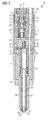
- FIG. 2 shows a schematic representation of a longitudinal section through a fuel injector 20 according to the invention.
- the fuel injector 20 essentially has an injector housing 38 which is connected to the assemblies servovalve 10, an intermediate plate 39, a needle guide body 40 and a nozzle body 41 is screwed by means of a nozzle lock nut 42.
- the injector 38 is preferably arranged as an actuator piezoelectric actuator 8, whose lower part is closed with a bottom plate 16, via which the changes in length of the actuator 8 directly to the underlying arranged Servovalve (valve unit) 10 are transferable.
- an O-ring 18 is provided for centering the bottom plate 16.
- a bellows 19 seals the actuator 8 against the located in a recess 17 fuel, which is designed as a leakage chamber 14.
- the leakage chamber 14 is connected to a leakage bore, not shown in FIG. 2, with the low-pressure region of the fuel system.
- a second spring 64 with a spring holder 62 causes an additional restoring force for the outer valve body 3.
- a continuous high pressure bore 9 can be seen, which is connected to the high pressure system of a fuel pump and the fuel injector 20 supplied with fuels such as diesel oil or gasoline , The fuel is fed directly to the nozzle tip.
- the nozzle body 41 is arranged with the intermediate plate 39 and the needle guide body 40.
- two coaxially mounted nozzle needles 26,28 are formed in the nozzle body 41.
- the outer nozzle needle 28 is guided in a central bore of the needle guide body 40. It is designed as a hollow needle and is completely penetrated by the inner nozzle needle 26 in the axial direction.
- the outer nozzle needle 28 is pressed by means of a first nozzle spring 30 against its located in the lower part of the nozzle body 41 outer valve seat 35. The located below the valve seat 35 first injection holes 34 are thereby closed.
- a second nozzle spring 32 is arranged, with which the inner nozzle needle 26 with its lower valve seat 33, the second injection holes 36 closes.
- the second nozzle spring 32 is preferably in a spring pocket 45 of the intermediate plate 39 for ease of installation arranged and supported against the head surface 80 of the inner nozzle needle 26 from.
- a first drain hole 44 is provided which connects the inner control chamber 4 with the spring pocket 45.
- the spring pocket 45 is guided downwards to a control chamber 70 which is formed in the needle guide body 40.
- the first drainage hole 44 is hydraulically coupled both to the spring pocket 45 and to the inner control chamber 4.
- a second drainage hole 72 is guided from the control chamber 70 to the outer control chamber 5 of the servo valve 10. Via the high-pressure bore 9, the fuel is conducted at a pressure of up to 2000 bar to the lower two valve seats 33, 35, so that the fuel can emerge after opening one or both of the nozzle needles 26, 28 from the corresponding spray holes 34, 36.
- a first inlet throttle 76 hydraulically couples the high-pressure bore 9 with the spring pocket 45.
- a second inlet throttle 78 hydraulically couples the high-pressure bore 9 to the control chamber 70 and the second drainage bore 72.
- the control chamber 70 is limited in its area by the head surface 80 of the inner nozzle needle 26 and the head surface 82 of the outer nozzle needle 28th
- the actuator 8 is extended so far that both control body 4.5 release their valve seats, the fuel in the control chamber 70 via the second drain line 72, the outer control chamber 5, pass past the conical seat 32 in the leakage chamber 14 and drain away there. This results in the control chamber 70, a further pressure drop, which eventually causes the outer nozzle needle 28 releases their injection holes 34.
Landscapes
- Engineering & Computer Science (AREA)
- Chemical & Material Sciences (AREA)
- Combustion & Propulsion (AREA)
- Mechanical Engineering (AREA)
- General Engineering & Computer Science (AREA)
- Physics & Mathematics (AREA)
- Fluid Mechanics (AREA)
- Fuel-Injection Apparatus (AREA)
Applications Claiming Priority (1)
| Application Number | Priority Date | Filing Date | Title |
|---|---|---|---|
| DE200410032700 DE102004032700B3 (de) | 2004-07-06 | 2004-07-06 | Kraftstoffinjektor mit einem Kugelsitz für ein zweistufiges Servoventil |
Publications (1)
| Publication Number | Publication Date |
|---|---|
| EP1614892A1 true EP1614892A1 (fr) | 2006-01-11 |
Family
ID=34939668
Family Applications (1)
| Application Number | Title | Priority Date | Filing Date |
|---|---|---|---|
| EP05103691A Withdrawn EP1614892A1 (fr) | 2004-07-06 | 2005-05-03 | Soupape d'injection de carburant avec une soupape à balle pour une servo valve à deux étapes |
Country Status (2)
| Country | Link |
|---|---|
| EP (1) | EP1614892A1 (fr) |
| DE (1) | DE102004032700B3 (fr) |
Cited By (1)
| Publication number | Priority date | Publication date | Assignee | Title |
|---|---|---|---|---|
| CN115523313A (zh) * | 2022-09-06 | 2022-12-27 | 泗洪智工精密机械有限公司 | 一种电控喷油器的燃油控制阀 |
Families Citing this family (1)
| Publication number | Priority date | Publication date | Assignee | Title |
|---|---|---|---|---|
| DE102005025638B4 (de) * | 2005-06-03 | 2007-09-20 | Siemens Ag | Schaltventil und Einspritzventil und ein Verfahren zum Steuern eines Einspritzventils |
Citations (4)
| Publication number | Priority date | Publication date | Assignee | Title |
|---|---|---|---|---|
| DE10158337C1 (de) * | 2001-11-28 | 2003-05-22 | Bosch Gmbh Robert | Kraftstoff-Einspritzvorrichtung, insbesondere Injektor für Brennkraftmaschinen mit Direkteinspritzung, sowie Kraftstoffsystem und Brennkraftmaschine |
| DE10222196A1 (de) * | 2002-05-18 | 2003-11-27 | Bosch Gmbh Robert | Kraftstoffeinspritzventil für Brennkraftmaschinen |
| DE10246974A1 (de) * | 2002-10-09 | 2004-04-22 | Robert Bosch Gmbh | Kraftstoffeinspritzvorrichtung für eine Brennkraftmaschine |
| WO2005057003A1 (fr) * | 2003-12-10 | 2005-06-23 | Siemens Aktiengesellschaft | Soupape d'injection de carburant |
Family Cites Families (3)
| Publication number | Priority date | Publication date | Assignee | Title |
|---|---|---|---|---|
| DE19858085C1 (de) * | 1998-12-16 | 2000-03-30 | Siemens Ag | Stellantrieb für einen Kraftstoffinjektor |
| GB9914646D0 (en) * | 1999-06-24 | 1999-08-25 | Lucas Ind Plc | Fuel injector |
| JP3865222B2 (ja) * | 2002-03-05 | 2007-01-10 | 株式会社デンソー | 燃料噴射装置 |
-
2004
- 2004-07-06 DE DE200410032700 patent/DE102004032700B3/de not_active Expired - Fee Related
-
2005
- 2005-05-03 EP EP05103691A patent/EP1614892A1/fr not_active Withdrawn
Patent Citations (4)
| Publication number | Priority date | Publication date | Assignee | Title |
|---|---|---|---|---|
| DE10158337C1 (de) * | 2001-11-28 | 2003-05-22 | Bosch Gmbh Robert | Kraftstoff-Einspritzvorrichtung, insbesondere Injektor für Brennkraftmaschinen mit Direkteinspritzung, sowie Kraftstoffsystem und Brennkraftmaschine |
| DE10222196A1 (de) * | 2002-05-18 | 2003-11-27 | Bosch Gmbh Robert | Kraftstoffeinspritzventil für Brennkraftmaschinen |
| DE10246974A1 (de) * | 2002-10-09 | 2004-04-22 | Robert Bosch Gmbh | Kraftstoffeinspritzvorrichtung für eine Brennkraftmaschine |
| WO2005057003A1 (fr) * | 2003-12-10 | 2005-06-23 | Siemens Aktiengesellschaft | Soupape d'injection de carburant |
Cited By (2)
| Publication number | Priority date | Publication date | Assignee | Title |
|---|---|---|---|---|
| CN115523313A (zh) * | 2022-09-06 | 2022-12-27 | 泗洪智工精密机械有限公司 | 一种电控喷油器的燃油控制阀 |
| CN115523313B (zh) * | 2022-09-06 | 2023-08-25 | 泗洪智工精密机械有限公司 | 一种电控喷油器的燃油控制阀 |
Also Published As
| Publication number | Publication date |
|---|---|
| DE102004032700B3 (de) | 2005-10-06 |
Similar Documents
| Publication | Publication Date | Title |
|---|---|---|
| DE10300045A1 (de) | Nach innen öffnende Variodüse | |
| DE102006008648A1 (de) | Kraftstoffeinspritzvorrichtung für eine Brennkraftmaschine | |
| DE10060812A1 (de) | Kraftstoffeinspritzsystem für Brennkraftmaschinen | |
| DE102008001597A1 (de) | Kraftstoff-Injektor | |
| EP1563182B1 (fr) | Injecteur dote d'un pointeau a niveaux a entrainement direct pour l'injection de carburant dans un moteur a combustion interne | |
| DE10306808A1 (de) | Injektor zum Einspritzen von Kraftstoff | |
| WO2002020975A1 (fr) | Soupape pour reguler le debit de liquides | |
| EP1144842B1 (fr) | Injecteur pour systeme d'injection de carburant pour moteurs a combustion interne, muni d'un pointeau faisant saillie dans la chambre de commande de soupape | |
| DE10353045A1 (de) | Kraftstoffeinspritzventil | |
| EP1682769A1 (fr) | Injecteur de carburant dote d'un element de soupape d'injection en plusieurs parties, en commande directe | |
| EP1614892A1 (fr) | Soupape d'injection de carburant avec une soupape à balle pour une servo valve à deux étapes | |
| DE10141221B4 (de) | Druck-Hub-gesteuerter Injektor für Kraftstoffeinspritzsysteme | |
| DE102007010498A1 (de) | Injektor zum Einspritzen von Kraftstoff in einen Brennraum einer Brennkraftmaschine | |
| EP2019198B1 (fr) | Injecteur | |
| EP1541859A1 (fr) | Injecteur | |
| EP2439398B1 (fr) | Soupape d'injection de combustible | |
| DE102008041553A1 (de) | Kraftstoff-Injektor | |
| EP2642110B1 (fr) | Soupape d'injection de combustible | |
| DE10323871A1 (de) | Injektor mit einer Registerdüse zur Kraftstoffeinspritzung | |
| WO2018082866A1 (fr) | Injecteur de carburant pour injecter un carburant gazeux et/ou liquide | |
| DE102005004897A1 (de) | Brennstoffeinspritzventil | |
| DE102016206261A1 (de) | Kraftstoffinjektor | |
| DE10333692B3 (de) | Kraftstoffeinspritzvorrichtung | |
| DE10003252A1 (de) | Einspritzdüse | |
| DE19754050A1 (de) | Einspritzventil zur intermittierenden Brennstoffeinspritzung |
Legal Events
| Date | Code | Title | Description |
|---|---|---|---|
| PUAI | Public reference made under article 153(3) epc to a published international application that has entered the european phase |
Free format text: ORIGINAL CODE: 0009012 |
|
| AK | Designated contracting states |
Kind code of ref document: A1 Designated state(s): AT BE BG CH CY CZ DE DK EE ES FI FR GB GR HU IE IS IT LI LT LU MC NL PL PT RO SE SI SK TR |
|
| AX | Request for extension of the european patent |
Extension state: AL BA HR LV MK YU |
|
| AKX | Designation fees paid | ||
| STAA | Information on the status of an ep patent application or granted ep patent |
Free format text: STATUS: THE APPLICATION IS DEEMED TO BE WITHDRAWN |
|
| 18D | Application deemed to be withdrawn |
Effective date: 20060712 |
|
| REG | Reference to a national code |
Ref country code: DE Ref legal event code: 8566 |