EP1605687B1 - Système pour recevoir des flux de paquets - Google Patents
Système pour recevoir des flux de paquets Download PDFInfo
- Publication number
- EP1605687B1 EP1605687B1 EP04253297A EP04253297A EP1605687B1 EP 1605687 B1 EP1605687 B1 EP 1605687B1 EP 04253297 A EP04253297 A EP 04253297A EP 04253297 A EP04253297 A EP 04253297A EP 1605687 B1 EP1605687 B1 EP 1605687B1
- Authority
- EP
- European Patent Office
- Prior art keywords
- packet
- stream
- tag
- circuitry
- packets
- Prior art date
- Legal status (The legal status is an assumption and is not a legal conclusion. Google has not performed a legal analysis and makes no representation as to the accuracy of the status listed.)
- Expired - Fee Related
Links
- 230000015654 memory Effects 0.000 claims description 62
- 239000000872 buffer Substances 0.000 claims description 43
- 238000004891 communication Methods 0.000 claims description 30
- 238000000034 method Methods 0.000 claims description 14
- 238000012545 processing Methods 0.000 claims description 4
- 238000003780 insertion Methods 0.000 description 12
- 230000037431 insertion Effects 0.000 description 12
- 230000006870 function Effects 0.000 description 10
- 230000005540 biological transmission Effects 0.000 description 6
- 238000006243 chemical reaction Methods 0.000 description 2
- 230000000694 effects Effects 0.000 description 2
- 238000001914 filtration Methods 0.000 description 2
- 230000003044 adaptive effect Effects 0.000 description 1
- 230000006835 compression Effects 0.000 description 1
- 238000007906 compression Methods 0.000 description 1
- 238000012937 correction Methods 0.000 description 1
- 230000001419 dependent effect Effects 0.000 description 1
- 238000005516 engineering process Methods 0.000 description 1
- 230000002452 interceptive effect Effects 0.000 description 1
- 239000000463 material Substances 0.000 description 1
- 238000012986 modification Methods 0.000 description 1
- 230000004048 modification Effects 0.000 description 1
- 230000004044 response Effects 0.000 description 1
- 230000001360 synchronised effect Effects 0.000 description 1
Images


Classifications
-
- H—ELECTRICITY
- H04—ELECTRIC COMMUNICATION TECHNIQUE
- H04N—PICTORIAL COMMUNICATION, e.g. TELEVISION
- H04N21/00—Selective content distribution, e.g. interactive television or video on demand [VOD]
- H04N21/60—Network structure or processes for video distribution between server and client or between remote clients; Control signalling between clients, server and network components; Transmission of management data between server and client, e.g. sending from server to client commands for recording incoming content stream; Communication details between server and client
- H04N21/63—Control signaling related to video distribution between client, server and network components; Network processes for video distribution between server and clients or between remote clients, e.g. transmitting basic layer and enhancement layers over different transmission paths, setting up a peer-to-peer communication via Internet between remote STB's; Communication protocols; Addressing
- H04N21/643—Communication protocols
- H04N21/64322—IP
-
- H—ELECTRICITY
- H04—ELECTRIC COMMUNICATION TECHNIQUE
- H04N—PICTORIAL COMMUNICATION, e.g. TELEVISION
- H04N21/00—Selective content distribution, e.g. interactive television or video on demand [VOD]
- H04N21/40—Client devices specifically adapted for the reception of or interaction with content, e.g. set-top-box [STB]; Operations thereof
- H04N21/43—Processing of content or additional data, e.g. demultiplexing additional data from a digital video stream; Elementary client operations, e.g. monitoring of home network or synchronising decoder's clock; Client middleware
- H04N21/438—Interfacing the downstream path of the transmission network originating from a server, e.g. retrieving encoded video stream packets from an IP network
- H04N21/4381—Recovering the multiplex stream from a specific network, e.g. recovering MPEG packets from ATM cells
-
- H—ELECTRICITY
- H04—ELECTRIC COMMUNICATION TECHNIQUE
- H04N—PICTORIAL COMMUNICATION, e.g. TELEVISION
- H04N21/00—Selective content distribution, e.g. interactive television or video on demand [VOD]
- H04N21/40—Client devices specifically adapted for the reception of or interaction with content, e.g. set-top-box [STB]; Operations thereof
- H04N21/45—Management operations performed by the client for facilitating the reception of or the interaction with the content or administrating data related to the end-user or to the client device itself, e.g. learning user preferences for recommending movies, resolving scheduling conflicts
- H04N21/462—Content or additional data management, e.g. creating a master electronic program guide from data received from the Internet and a Head-end, controlling the complexity of a video stream by scaling the resolution or bit-rate based on the client capabilities
- H04N21/4622—Retrieving content or additional data from different sources, e.g. from a broadcast channel and the Internet
Definitions
- the present invention relates to a system for receiving transport streams and in particular but not exclusively to a system for use in a set top box.
- the television In digital television systems, the television is provided with a set top box to receive and decode a broadcast digital data stream which contains program information for display on the television.
- the broadcast digital data stream may arise at the set top box via a satellite or cable system, via a digital terrestrial system, via the internet, or via disk or tape.
- a disk or tape such as a CD ROM in a personal computer, may provide digital video information for display on the monitor.
- each transport packet after encoding (for example using Viterbi and Reed-Solomon Channel coding) is defined by the standard as consisting of 188 bytes, (although other lengths are possible, E.g. DVB-H) comprising a minimum of four header bytes and a maximum of 184 payload bytes ("the data payload").
- the transport packets are time division multiplexed into a transport stream.
- the transport stream is demultiplexed to recover the transport packets.
- the transport packets may be scrambled and encoded with error correction information for transmission and then descrambled and error checked at the receiver.
- the payload in the transport packets is, according to the MPEG-2 standard, one of two types. The first type is known is a packetised elementary stream (PES), and the second type is known as program specific information (PSI).
- PES packetised elementary stream
- PSI program specific information
- the packetised elementary streams form the video, audio and private data information of the broadcast.
- a PES packet may contain all sorts of data, audio or video and also other information such as teletext or other user defined general data.
- the MPEG-2 transport stream is made up of one or more PESs (either video, audio or private).
- the MPEG-2 transport stream is primarily intended for the transport of TV programs over long distances. This type of stream can combine, in the same multiplex, many programs, each of them being composed of one or more PESs.
- the MPEG-2 standard defines all types of tables, which together make up the MPEG-2 program specific information (PSI), which is information associated with the audio, video or private data of the PES.
- PSI MPEG-2 program specific information
- each set top box is provided with a transport interface, which provides an input interface between the transport stream input to the box and the actual MPEG-2 decoders which decode the audio and video information and sections broadcast.
- the transport interface demultiplexes the transport stream to retain only those transport packets, which are required by the particular set top box for decoding.
- the transport stream is a set of different services time division multiplexed and the purpose of the transport interface is to demultiplex them.
- a time demultiplex function is performed to separate the transport stream into its component transport packets.
- Each transport packet has associated therewith in its header a packet identifier (PID) which identifies the type of packet and various information associated with the data in the packets including the type of packet (PES or PSI).
- PID packet identifier
- PSI packet identifier
- Each particular receiver or set top box is only interested in receiving packets having packet identifiers of interest to the particular set top box, for instance those associated with the particular program selected for viewing.
- the transport interface merely uses the header of PES transport packets to demultiplex them, and stores the data payload (ES) of the demultiplexed packets in the memory.
- the transport interface similarly demultiplexes PSI transport packets but then filters the sections of the demultiplexed packets to retain only sections required by the receiver, before storing the filtered sections in the memory without further processing.
- one or more streams of MPEG data may be obtained from a memory instead of via a satellite or cable link.
- This data may or may not be in the form of a transport stream, but may be packets of data comprising audio, video, private and/or associated information.
- This data may be received from local memory, such as a hard disk, or from memory in a remote station via a network link.
- the PID of a particular packet within that stream must be interpreted differently by the transport interface. For instance the same PID value might be present in a received packet which is part of a packet stream received via a satellite signal and a received packet which is part of a packet stream originating from a remote station via a network interface, however only packets from one of these streams may be required by the receiver. In another example the same PID value might be present in packets received in packet streams from different remote stations via the network interface, and likewise only the stream currently being viewed may be required by the receiver.
- EP-A-1089522 describes an adaptive transport protocol decoder in which streams of packets having different transport protocol are received and decoded accordingly.
- the packet headers include information to assist with decoding.
- EP5847771 describes a digital entertainment terminal that simultaneously decodes two MPEG-encoded digital data streams to provide a Picture-In-Picture display.
- US6,441,841 describes a combined picture generating apparatus by extracting and combining intra-frame coding pictures.
- US2004/0017831 describes a method of processing service information data from a plurality of input streams into at least one input stream.
- US6,160,545 describes the delivery of interactive program content carried via a satellite network and another network.
- a system comprising: at least one input means for receiving from one of a plurality of sources at least one packet stream comprising a plurality of packets for providing audio, video, private data and/or associated information; at least one output for outputting at least one packet of said at least one packet stream to circuitry arranged to provide an output stream; each packet of the plurality of packets being associated with a one of a plurality of programs and having a packet header containing a packet identifier PID which identifies an information type and program associated with the packet; characterised by: the system being arranged to determine and output to said circuitry a tag indicative of said source, said tag being associated with said at least one packet in addition to the packet identifier; the system being further arranged to output said at least one packet to said circuitry via a first communication line and provide the tag to said circuitry separately from said at least one packet on a second communication line separate from said first communication line; wherein at least one of said input means is a software input port
- a set top box comprising receiving means and a device, said device comprising: at least one input means for receiving from one of a plurality of sources at least one packet stream comprising a plurality of packets for providing audio, video, private data and/or associated information; at least one output for outputting at least one packet of said at least one packet stream to circuitry arranged to provide an output stream; wherein each packet of the plurality of packets being associated with a one of a plurality of programs and having a packet header containing a packet identifier PID which identifies an information type and program associated with the packet; the set top box characterised by: the device being arranged to determine and output to said circuitry a tag indicative of said source, said tag being associated with said at least one packet in addition to the packet identifier; the device being further arranged to output said at least one packet to said circuitry via a first communication line and provide the tag to said circuitry separately from said at least one packet on a second communication line separate from said first communication line; where
- a packet stream comprising the steps of:
- an MPEG-2 transport packet stream or other type of packet stream, is demultiplexed in a programmable transport interface of a receiver in a digital set top box.
- the present invention is not limited to such an application and does in fact have broader applicability to other types of digital data and other types of application for example ATM address filtering, Ethernet address filtering or the like.
- the present invention is particularly effective where packet streams are received from more than one source.
- other circuitry may be used to demultiplex the packet stream, for example a fix hardware engine.
- the present invention is applicable where any circuitry may need to know the source of a packet stream, for example in order to distinguish streams from each other.
- Devices that comprise embodiments of the present invention can be incorporated into a multitude of hardware, for example set top boxes, digital video players, multimedia devices or mobile stations or devices. These devices may include MPEG decoders.
- Set top boxes can include any device associated with a display, and may for example be network capable, low cost, internet protocol (IP) boxes and may incorporate digital video recording (DVR) functionality.
- Digital video players may be digital versatile disk (DVD) players or recorders.
- the multimedia devices or systems may be portable, video hand held devices with a USB, firewire or alternative interface, and may include MP3 playback.
- Mobile devices or stations may be digital video broadcast handheld (DVB-H) capable devices, which may included telephone functions and also include MP3 players.
- DVD-H digital video broadcast handheld
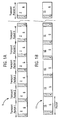
- Figure 1A illustrates a portion of a transport stream 1 which is composed of a series of n transport packets 2.
- the transport stream is in the format of an MPEG-2 transport stream.
- Such a transport stream may for example be received by a set top box via a satellite, cable, or terrestrial signal receiver, or via an interface to a network.
- Each transport packet 2 comprises a transport packet header 4 and a transport packet payload 6.
- the transport stream is a bit stream which carries in the transport packet payloads 6 information for recreating, for example, a number of different programs.
- the transport stream is formed by source encoding the television programs.
- the transport stream is then typically channel encoded for transmission (by satellite, cable, via a network interface or other means) and channel decoded on its reception to reproduce the transport stream.
- the transport stream is then source decoded to recreate a selected one of the different television programs.
- Figure 1B illustrates a portion of a software packet stream 11.
- the term software stream is used throughout this application to distinguish a packet stream received from a memory, rather than from a satellite/cable receiver, however the software stream may be identical to the transport stream shown in Figure 1A .
- a Software packet stream may originate, for example, from a flash memory or a hard disk drive, and be send to the demultiplexing/decoding circuitry by a direct memory access unit as will be described in more detail hereinafter.
- Each software packet 15, like transport packets also contains a packet header 4 and a payload 6, however the packet headers 4 may need to be added by a direct memory access unit if the data is not already in this format.
- the software packet stream 11 may not be in the format of a transport stream, for example it may have variable length packets, in other respects it is the same and may be treated in the same way.
- packet stream will be used throughout to mean a transport stream 1 and/or a software stream 15.
- Each particular television program received as a packet stream requires three types of information for its recreation.
- the three types are audio information, video information, private data information and tables of program information which are associated with the audio and video information and provide control information.
- Private data could be for example security information or software update information for updating the software in a set top box.
- Each transport packet 2 is preferably associated with a particular program, a particular source encoding time and a particular one of the information types.
- the individual transport packets are time division multiplexed to form the transport stream and allow the real-time recreation of any one of the different programs from the transport stream.
- To recreate a program the transport stream is sequentially demultiplexed to recover only the transport payloads 6 of audio or video information, private data and tables of program information which are associated with the selected program. The recovered payloads are then decoded and used to recreate the program.
- the software packet stream 11 is also demultiplexed to recover the payloads 6 of audio, video and private information and tables of program information, which may be decoded to recreate the program.
- the term program is used to cover television programs, films, audio recordings, video recordings or the like.
- each of the transport packets 2 is 188 bytes long and the standard transport packet header 4 is four bytes long (however the header is expandable up to the whole packet length).
- the transport packet payload 6 contains either audio, video or private data information or sections. The sections are parts of tables. The audio and video information and the sections in the payloads 6 are packetised and encoded in accordance with MPEG-2 DVB compression standard. Data packets 15 of software packet stream 11 may also be encoded according to the MPEG-2 standard, however the data may also be packetised in different lengths, with a greater or fewer number of bytes in the header 4 or payload 6.
- the system is arranged not only to receive MPEG data in the form of packet streams from a satellite or cable link, the system is also able to receive software packet streams originating from data stored on a hard disk, a floppy disk or any other suitable source in local memory within the receiver, or from a remote station via a network interface.
- Transport streams 203 and 205 from a cable or satellite link are input to a transport stream merger TSM 202. Although this is not shown, a further link to receive a terrestrial signal could be provided.
- the TSM 202 has a software register 204 for receiving software packet streams on line 207.
- the function of the TSM 202 is to route packet streams from a variety of packet stream sources to a variety of packet stream targets in the form of programmable transport interfaces.
- the TSM 202 has two outputs on lines 212 and 214 to respective programmable transport interfaces 206 and 208.
- the TSM 202, the software register 204 and the programmable transport interfaces will be described in more detail hereinafter.
- the system has a bus 240 which provides interconnections between elements of the system which will now be described.
- a hard disk drive 224 is provided. Programs which are stored on the hard disk drive may be replayed via the software register 204 of the TSM 202.
- the hard disk drive 224 is arranged to interface with the other elements of system via a hard disk drive interface 226.
- a CPU 228 is also provided. This CPU 228 may alternatively or additionally be arranged to store programs which can be replayed via the software register 204.
- the CPU 228 has a SRAM 229 which stores the programs to be replayed.
- a DMA direct memory access unit 230 is provided.
- the DMA unit 230 can be configured to read blocks of data from one address and write them to another, for example from the hard disk to the TSM 202 and in particular its software register. This can be done with little intervention from the CPU. In particular the CPU just needs to program the DMA.
- a network interface 232 is also provided.
- the network interface 232 provides a connection to one or more networks external to the system, including the internet and the world-wide web. Packet streams may be transmitted to the TSM from remote stations (not shown) via the network interface 232. Programs may also be downloaded from remote stations connected to the internet, and stored on hard disk 224 to be replayed later.
- the system includes output hardware elements for viewing programs.
- a video and display CODEC coder-decoder unit 236 provides an output to a display device 244 which could be a television or display monitor.
- the type of connection to the display 244 can be any of a number of connections including a SCART connection, S-video connection or RF connection.
- An audio unit 238 is also provided for outputting sound to an external amplifier or speaker system, and can support stereo or surround sound formats.
- An EMI external memory interface 233 provides an interface for connecting to external memory (not shown), and a FMI flash memory interface 234 provides an interface for connecting to flash memory (also not shown). These memories may be internal or external to the system.
- a SATA serial advanced technology attachment unit 242 provides a serial interconnection to a hard disk, digital versatile disk, compact disk or the like. These memory resources may be used to store program data from programmable transport interfaces 206 or 208, or other data for use in encoding or decoding the data for instance.
- the programmable transport interfaces 206 and 208, DMA 230, CPU 228, network interface 232, hard disk drive interface 226, EMI 233, FMI 234, video and display CODEC 236, audio unit 238 and SATA unit 242 are all connected to bus 240 which allows these elements to communicate with each other.
- One of the two programmable transport interfaces of Figure 2 is shown in more detail in Figure 3 and is used to process a packet stream and produce a data output stream suitable for reconstitution as a television program after MPEG-2 decoding by MPEG-2 decoders (not shown).
- the programmable transport interface 10 is included in a receiver which receives the transport stream 1, or software stream 11 and it may process one or multiple packet streams at the same time.
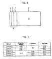
- a transport packet is shown in more detail in Figure 4 .
- the transport packet header 4 contains a synchronisation byte 3 which identifies the beginning of each transport packet 2.
- the transport packet header 4 also contains a packet identifier (PID) 7 which identifies the information type and the program associated with the transport packet payload 6.
- the transport packet 2 also contains information identifying the source encoding time of the transport packet.
- a tag 5 is also included in the transport packet header 4, described in more detail herein after.
- the transport packet header 4, including the synchronisation byte 3, tag 5 and the PID 7, is not scrambled.
- the transport packet payloads 6 may be scrambled.
- Data packets 15 of the software packet stream 11 also include PID 7, and tag 5, and may also include a synchronization byte 3.
- the programmable transport interface (PTI) 10 performs functions such as disregarding packets which are not required (i.e. if they do not relate to a selected program), descrambling packets, and demultiplexing the packet stream to produce a data output stream.
- Information relating to a packet stream (described in more detail herein after) is stored in SDRAM within the PTI 10, and is used in performing these functions.
- packets are selected and processed using the information selected from the SDRAM on the basis of the PID 7 in each packet.
- the PID value alone is not sufficient for the selection and processing of packets.
- Embodiments of the present invention provide a tag 5 in the header 4 of each packet 2 or 15.
- This tag indicates the origin of the transport or software packet. That is to say it is indicative, in the case of a packet received in a software stream, of an address, known by the TSM 202, from which the packet was sent.
- the tag 5 indicates the external port of the TSM 202 which received the transport stream.
- the tag 5 comprises one byte of data; however in other embodiments it could comprise only a few bits of data, or more than one byte.
- Transport or software packets are tagged by the TSM 202, as described later herein. The PTI 10, which selects and processes packets using this tag 5, will now be described.
- the PTI 10 performs the following functions:
- the data output stream 20 comprises a stream of audio information associated with the selected program, a stream of video information associated with the selected program or tables of program information associated with the selected program.
- the PTI outputs the streams to the necessary MPEG-2 decoder to reproduce the selected program, or to memory via the TSM 202 for decoding later.
- the programmable transport interface 10 comprises an input interface.
- the input interface 22 receives software or transport packets from the TSM 202 and implements a handshake protocol with the TSM 202 in order to ensure that packets of the packet stream are transmitted on data line 47 without error.
- a handshake protocol In the present embodiment an RG (Request/Grant) protocol is used, however it will be apparent to those skilled in the art that any suitable handshake protocol could be used, or none at all.
- a data line 47, a request signal on line 46 and a grant signal on line 48 are provided between the input interface 22 of the PTI 10 and the TSM 202.
- the TSM 202 may request communication with one of the PTI 10, when for example a transport packet is ready, by asserting the request signal on line 46 (e.g. sending a high signal). If the input interface 22 is ready to accept the packet stream, it responds by asserting the grant signal 48. Once the packet has been sent on data line 47, the TSM 202 changes the request signal 46 to low, and in response the input interface 22 changes the grant signal 48 to low.
- a further 'valid' signal may be provided (not shown in the figures) between the TSM 202 and the input interface. The valid signal indicates when the transport stream signal on data line 47 has been processed and there is free space in the fifo or memory subsystem of the PTI 10.
- the input interface 22 identifies the synchronisation byte of each packet which is used to synchronise the system clock and the packet stream.
- the input interface 22 is controlled by the transport core 24 of a transport controller 26 via input interface control signals from the transport controller core to the input interface.
- the control signals may include a descrambling control signal and output stream control signals.
- the input interface 22 provides bits to the transport controller 26 via a buffer 28.
- the buffer 28 is used to temporarily store data from the input interface, when required.
- the input interface 22, under the control of the transport controller core 24 descrambles the payload 6 of selected packets and supplies selected descrambled payloads to the transport controller 26.
- the transport controller 26 comprises a section filter 30 and search engine 32 in addition to the transport controller core 24.
- the transport controller 26 operates on the bits received from the input interface 22.
- the transport controller 26 receives from the input interface 22 the packet header 4 of the transport packet 2 or software packet 15 arriving at the input interface 22.
- the transport controller 26 uses the tag 5 and the packet identifier 7 in the packet header 4 to determine whether the packet now entering the input interface is associated with the selected program for the programmable transport interface 10. If it is not, the received packet is discarded. If it is, it controls the input interface 22 to descramble, if necessary, the packet payload 6 as described above, and to supply the packet payload 6 to the transport controller 26.
- the transport controller 26 may pass a payload 6 associated with the audio or video information for the selected program straight to the transport controller output 34. If the payload relates to a section of a table the transport controller may further process the information before providing it at its output 34.
- the transport controller core 24 of the transport controller 26 reads instruction sets from an instruction SRAM 36.
- the transport controller 26 is connected to the SRAM 36 by interconnect 38 and it reads its instructions via that interconnect.
- a system processor (not shown) may read and write to the instruction SRAM 36.
- the transport controller 26 has preferential access to the instruction SRAM 36 determined by an arbiter (not shown) which arbitrates between accesses by the transport controller 26 and the system processor.
- the PTI 10 also comprises a data SRAM 40 which again can be accessed by the transport controller core 24.
- data is written to and read from the data SRAM 40 via interconnect 42.
- the search engine 32 in the transport controller 26 is also able to read data from the data SRAM 40.
- the search engine 32 searches the data SRAM 40 for the packet identifiers 7 associated with the packet source indicated by the tag 5 in the incoming packet header 4.
- the tag value only exists as far as this stage, and it may now be deleted from the packet header.
- the tag 5 maybe left in the packet header and provided to compatible devices/systems capable of reading it to perform dejittering functions off-chip or in other areas within the device.
- the PID for a packet from that source will have been stored in the data SRAM and is located by the search engine 32 of the transport controller 24.
- Associated with each packet identifier 7 and tag 5 in the data SRAM 40 is a plurality of pointers, which point to other addresses in the data SRAM where other information associated with the incoming transport is stored.
- the search engine retrieves the pointer stored with a particular packet identifier for a particular packet source but used by the transport controller core 24.
- the transport controller core 24 uses the pointers to access all the information it needs to process the payload of the incoming packet.
- the pointers may, for example, point to descrambling keys for use by the input interface 22, point to addresses for use by a direct memory access controller 44, identify whether the payload is video or audio information or sections, or identify whether the payload is special data to be output on an alternative output etc.
- the information obtained from the data SRAM 40 enables the transport controller to control the PTI 10.
- the transport controller 26 produces the transport controller output 34 which is supplied to a multi channel direct memory access controller 44.
- the multi channel direct memory access controller 44 supplies the data output stream 20, indirectly, to the MPEG decoders (not shown).
- the TSM 202 has two transport stream interfaces 302 and 304 through which external transport streams can be brought in on lines 203 and 205 respectively.
- the external transport streams may be from satellite or cable links, or received from digital broadcasters.
- the function of the transport stream interfaces 302 and 304 is to provide an interface between the external transport streams 203, 205 and the rest of the transport stream merger 202.
- the interfaces synchronise the transport stream to the system clock and convert where appropriate an external serial stream into a byte wide parallel stream.
- the external stream may already be in a parallel mode in which case the interfaces 302, 304 would not need to perform serial to parallel conversion, but would still perform synchronization.
- Each interface 302, 304 includes an input buffer 454, 456 which are FIFO first-in-first-out buffers capable of storing a number of bytes, for example 256 bytes of received data from the external source.
- the size of these buffers will be determined based on the size of the received packets, the bit rate of the received stream, and the rate at which the buffer may be emptied.
- the size of these buffers is programmable by CPU 228, such that if overflow occurs more memory may be allocated, as explained in more detail below.
- External transport streams 203 and 205 may be received at interfaces 302 and 304 at different rates.
- a complete packet When a complete packet has been received, for example a transport packet with four bytes of header data and 184 bytes of payload data, it may be output from the transport interface to one of the outputs 492 and 494.
- Additional functionality within the interfaces 302, 304 enables an asynchronous or synchronous (to the transport stream byte clock) packet clock from an external transport source to be detected.
- the interfaces are responsible for converting the streams to the required bus protocol of the system if required, however according to preferred embodiments of the present invention the protocol used before and after interfaces 302, 304 is the same, i.e. the Digital Video Broadcasting Transport Stream (DVB-TS) protocol, and therefore no conversion it required.
- DVD-TS Digital Video Broadcasting Transport Stream
- a software register 204 is provided in the TSM 202 which allows the input of the software packet streams using direct memory access unit 230, or from any of the elements 226 to 232, via bus 240 ( Figure 2 ).
- a single software register port is provided for all software transport streams, that is to say all a single port is provided for all those streams not received from satellite or cable sources. In one modification, a plurality of ports which are shared may be provided.
- the software register 204 also allows the input of transport streams from an external network via the network interface 232, or from SRAM 229 associated with the CPU 228. In other words the software register 204 allows the playback of material which is already stored in a memory or the like.
- This memory can be any suitable memory as discussed above and may for example be a memory of the CPU 228, a hard disk drive 224, a SDRAM, or removable media such as a floppy disk, CDROM, DVD or the like (not shown) or alternatively the memory of a remote device accessible via the network interface 232.
- the software register 204 is a software writable transport stream register. This register can be used to copy one or more packet streams from memory and stream them to either of the programmable transport interfaces 206 or 208. Buffers 402 to 406 are provided, allowing up to three software packet streams to be received via lines 470 to 476, each stream being designated a particular buffer. In other embodiments more or less buffers may be provided. The register is described in more detail herein after.
- the TSM 202 has output lines 492 and 494 to PTI 206 and 208 respectively.
- Each of the output lines 492 and 494 to respective PTI comprise a data line 47 and request and grant lines 46 and 48, which are also shown in Figure 3 , and a handshake protocol is implemented as described in relation to Figure 3 .
- the TSM 202 also includes ports 462 and 464 providing connection to the two programmable transport interfaces 206 and 208 respectively, and allowing output data streams to be received from each of the PTI.
- the ports implement a handshake protocol when communicating with the programmable transport interfaces 206 and 208, as described above in relation to figure 3 .
- the ports include buffers 466 and 468 respectively, which are each, for example, 256 bytes in size. Output data streams received via these ports may be stored in memory via EMI 233, FMI 234, Serial ATA 242, HDD 224 or other external memory via network interface 232.
- SDRAM 452 in the TSM 202 provides memory resources for use by the input ports and also the software transport stream register 204.
- the TSM 202 implements a system of virtual buffers, allowing the physical memory to be efficiently allocated to the elements that require use of the memory for the buffers and registers described above.
- CPU 228 may access and control TSM 202 via control bus 490 and configuration registers 316, as will be described in more detail hereinafter.
- a programmable tag register 480 is also provided in the TSM 202, the operation of which will now be described with reference to Figure 7 .
- the programmable tag register 480 is used for determining the tag byte that is to be inserted into the header of each transport packet received by the TSM 202.
- the tag value could be provided by hardware, however using a programmable register means that the system is adaptable.
- the tag byte value is dependent on whether the transport stream is received by one of the two external ports 302 or 304, or other external ports if these are provided, or if the stream is a software packet stream received by software register 204.
- the programmable tag register 480 stores a value associated with each external transport stream as shown in the second column of the table in Figure 7 .
- a first external stream received at port 302 of the TSM 202 is associated with a value 0x00 (hexadecimal).
- a second external stream received at port 304 of the TSM 202 is associated with a value 0x01 in the register, and further external streams (not included in the present embodiment) can be assigned values up to 0x0F.
- the value held for all of the software packet streams is 0x10.
- the tag inserted into the header of each packet for the external streams will be simply the register value associated with that stream as explained above.
- the value of the tag byte in the case of the software packet streams is the register value added to a plurality of the LSB least significant bits of the address from which stream originates. This address is received by the TSM 202 on line 474 from the bus 240. For example, as shown in Figure 7 , if the address from which the transport stream is sent ends with 0x00, then the tag byte inserted in the packet headers of this stream will be 0x10. If the value is 0x01, then the tag byte will be 0x11. If there are 'n' software streams, then the nth stream will have a tag byte of 0xFF. Thus in this embodiment, tag values between 0 and 0x0F are reserved for external streams by offsetting the software stream tags by 0x10.
- Tag insertion circuitry 482 is also provided within TSM 202 for inserting the tag into the transport packets.
- Tag insertion circuitry 482 includes a byte counter 484 which locates the position within the packet for inserting the tag.
- the packets may be of varying sizes, and data relating to their sizes is stored in a length register 408. Values in the length register are programmable by the CPU 228. This data may be used by the tag insertion circuitry for locating the position for inserting the tag in the case of software transport packets.
- a tag is inserted at the time when transport stream data is received and stored in one of the buffers 454, 456 associated with the external transport streams, or one of the buffers 402, 404, 406 associated with the software transport streams. Tag insertion in the case of external transport streams will be described first.
- the tag insertion circuitry uses the data associated with the input port stored in the tag register 480 to determine the value of the tag to be inserted. This value may then be inserted directly into the required position in the packet, the position being located by the byte counter 484. As described in relation to Figure 4 , preferably the tag is inserted into the packet header 6, however alternatively the tag could be inserted into the payload 6 of the packet. In yet a futher embodiment, the tag 5 could be stored in the input buffer memory 454 separately from the packet. The packet is then ready to be sent to either of the PTI 206 or 208, on communication lines 492 or 494 respectively. The tag 5 will either be sent in the packet header, or in alternative embodiments the tag may be sent in the packet payload or directly before or after the packet.
- the address received on line 474 associated with that packet is used by the tag insertion circuitry 482 to determine the value of the tag for insertion into the packet.
- a number of the least significant bits of the address are added to an offset to determine the value of the tag.
- the tag 5 may be inserted into the header 4 or the payload 6 of the packet, or alternatively inserted into the memory separately from the packet. The packet is then ready to be sent to one of the PTI 206 or 208, and the tag 5 may be send before, within or after the packet.
- Figure 5B shows a second embodiment of the present invention.
- tag signal circuitry 286 and byte counter 288 are provided to replace tag insertion circuitry 482 and byte count 484.
- signals 496 and 498 are provided to PTI 206 and 208 respectively from the tag signal circuitry 286. All other components in Figure 5B are the same as those components of Figure 5A with the same references, and will not be described again.
- the tag is inserted into the packet, or provided before or after the packet on data line 47, according to the second embodiment shown in Figure 5B the tag 5 is provided on a separate line 496 or 498 from the packet, which is sent on lines 492 or 494. This is known as off-band signalization. Operation of the tag signal circuitry 286 of Figure 5B will now be described.
- the tag signal circuitry 286 determines the value of the tag 5 to be inserted in the same way as the tag insertion circuitry 482, using values stored in the tag register 480, and in the case of software packets, the address on line 474. Then, rather than inserting the tag into the buffer, the tag signal circuitry waits until the packet is ready to be sent to one of the PTI 206 or 208. At the same time the packet is sent on lines 492 or 494, the tag byte 5 is also sent on lines 496 or 498, the packet arriving at the PTI at the same time as the tag byte. The PTI will use the tag 5 in the same way as if it were provided within the packet header.
- the software register 204 of Figures 5A and 5B is shown in more detail in Figure 6 which will now be described.
- Data bytes or words are first written to a data register 400 by a DMA or CPU or the like.
- Interface circuitry 410 provides an interface allowing communication with the bus 240 (shown in Figure 2 ) in a standard request grant RG protocol using the four signals request 470, grant 472, address 474 and data 476.
- the request signal on line 470 is asserted by the CPU or DMA or other device when access to the software register is required.
- the grant signal on line 472 is always asserted by default, unless there are less than a certain number of byte locations available in one of the first-in-first-out FIFO memory 402, 404, 406, as described in more detail below.
- Software packet stream data is received on line 476, and this data may represent one or more software transport/packet streams. Address information relating to the address from which the packet stream currently being received has originated is received on line 474.
- the data register has 32 bits.
- the written data is then forwarded to one of the three first-in-first-out FIFO buffers 402 to 406, each of 256 bytes which are used to buffer the data.
- the size of each buffer is programmable by CPU 228 as described in more detail herein after.
- Each software stream is sent to a different FIFO buffer. In the present embodiment three such buffers are provided, however this is software configurable, and more or less buffers could be provided depending on the available memory resources. Providing more FIFO buffers would allow a greater number of software streams to be received simultaneously.
- the FIFO buffers 402 to 406 convert the data into byte wide transport streams.
- the grant signal on line 472 remains high allowing the CPU or DMA to read more data to the buffer. If less than a minimum number of empty bytes are left in one of the FIFO, then the grant signal on line 472 goes low, telling the CPU or DMA that the buffer is nearly full. Data is then emptied from the buffer before more data is received. As shown in Figure 6 , a full signal 412 is provided from the FIFO buffers 402, 404 and 406, determining when the grant signal should be asserted. The minimum amount of empty space required in a FIFO buffer for data to continue to be read to it is determined by the burst size of the received data, but could be for example 64 bytes.
- the size of the FIFO buffers is programmed by the CPU. If required more of less memory may be allocated to each the buffers, depending on the number buffers and streams being received, the bite rate of received streams, the size of the packets and the rate at which a stream may be processed.
- Bs is the buffer size
- Ps is the packet size of received packets
- Ts is the bit rate of the incoming stream
- B is the rate at which the stream may be processed
- n is the number of streams being received, which in the present embodiment is equal to the number of buffers. For example if first and second buffers are provided, each receiving a stream, then the size of the first buffer can be determined as follows.
- the software register 204 also includes a length register 408 which stores the packet lengths of packets in each of the received packet streams.
- the values in the length register 408 are programmed by the CPU, and are used to configure the device to the type of packets being received.
- the register may then be used by the byte counter 484 for locating where to insert the tag 5. This value is also used for determining when a whole packet has been received and may be outputted to one of the PTI.
- the use of the software register 204 allows transport stream to be stored on the hard disk and then replayed allowing fast forward, rewind and similar functions. It also allows programmes to be viewed via the network interface 232, and internal back-buffering.
- the software register 204 will start outputting it to one of the programmable transport interfaces.
- a decision can be made, determined by the available resources of each programmable transport interface 206 or 208 as to which of these interfaces a particular stream will be sent.
- the data may have any suitable format.
- the data output by the software register 204 will be little endian. This means that the least significant byte contains the byte which is first output by the software register 204.
- Figure 8 illustrates how digital signals 809, 811 and 813 can be transmitted via a cable, satellite or terrestrial channel 852 and be viewed on a display 890.
- the first, second and third signals 809, 811 and 813 each represent the audio and video signals necessary to recreate a program for input to a display.
- the digital signals 809, 811 and 813 are source encoded and channel encoded by a transmitter 850 to produce a modulated analogue signal for transmission on the channel 852.
- An integrated receiver decoder also known as a set top box 880 receives the modulated analogue signal from the channel 852 and produces a video signal 839 which operates the display 890.
- the transmitter includes a source encoder 810 and a channel encoder 840.
- the source encoder includes first, second and third MPEG 2 encoders 812, 814 and 816, first, second and third packetisers 818, 820 and 822, first, second and third scramblers 824, 826 and 828 and a multiplexer 830.
- First, second and third MPEG-2 encoders respectively receive first 809, second 811 and third 813 signals and encode the signals to produce first, second and third elementary bit streams 815, 817 and 819.
- the first 818, second 820 and third 822 packetisers respectively receive first 815, second 817 and third 819 elementary bit streams and packetise the elementary bit streams to produce first, second and third packetised elementary bit streams (PES) 821, 823 and 825.
- the packetising of an elementary bit stream includes creating series of packets which contain a packet head and a data portion, but which do not have any fixed length.
- the first, second and third scramblers respectively receive first, second and third packetised elementary bit streams and produce first, second and third scrambled packetised elementary bit streams. Each of the scramblers scrambles only the data portion of each packetised elementary bit stream it receives and does not scramble the packet header.
- the multiplexer 830 receives as inputs packetised sections of tables on line 841 and the first, second and third scrambled PES 827, 829 and 831 and produces a transport stream from one of its inputs on line 801.
- the packetised sections with tables 841 contain information which allows the set top box 880 to effect source decoding and produce the video signals 839.
- the information is stored in a tabular form where each table contains a number of sections and each section is transmitted individually.
- the multiplexer 830 produces the transport stream 801 such as that illustrated in Figure 1 .
- the transport stream includes a number of transport packets with each transport packet containing a transport header 4 and a transport packet payload 6.
- Transport packets have a fixed length. In the MPEG-2 digital video broadcast (DVB) standard the transport packet is 188 bytes in length. Transport packets are shorter in length than the packets in the packetised elementary stream. Consequently a packet from the first scrambled PES 827 will be spread over a number of transport packets and these transport packets will be multiplexed with the transport packets derived from the packetised sections in tables 841 and the second and third scrambled PES 829, 831.
- the transport stream is then supplied on line 801 to the channel encoder 840 to produce the modulated analogue signal for transmission on the channel 852.
- the channel encoder 840 includes a circuitry 832 for forward error correcting (FEC) the transport stream on line 801 and a digital to analogue converter for converting the signal from the digital to analogue domain to produce an analogue signal 833.
- the analogue signal 833 is modulated and up converted to a transmission frequency by the circuitry 834 to produce the modulated analogue signal which is then transmitted into the channel 852.
- the set top box 880 includes the system of Figure 2 but for the purposes of clarity not all of the elements of that figure are shown.
- the set top box 880 includes a channel decoder 860 and a source decoder 870.
- the channel decoder 860 receives a modulated analogue signal on the channel 852 and produces the transport stream 1 which it supplies to the source decoder 870.
- the channel decoder 860 includes circuitry 862 for tuning to the modulated analogue signal on the channel 852 and for down converting and demodulating the modulated analogue signal on the channel 852 to produce an analogue signal 837.
- the analogue signal 837 is converted from analogue to digital in an analogue to digital converter and forward error corrected by the circuitry 864 to reproduce the transport stream 1.
- the source decoder 870 receives the transport stream 1 and produces the video signal 839.
- the source decoder 870 includes the programmable transport interface 10 and MPEG-2 decoder 872.
- the PTI 10 (only one of which is shown for clarity) demultiplexes the transport stream 1, selects the transport packets 2 carrying information relating to a particular program, and descrambles the selected transport packet to produce a data output stream 880, which is in fact the packetised elementary bit stream associated with the selected program.
- This stream may be stored in memory (not shown in Figure 8 ) for example flash memory via FMI 234 ( Figure 2 ). It should be appreciated that the transport stream may not have been received via a cable or satellite connection and may have been received by the software register 204.
- the MPEG-2 decoder 872 receives the data output stream 880 and produces the video signal 839 which is supplied to the display 890.
- the display 890 displays the selected program.
- Some embodiments of the present invention may not receive transport streams from cable, satellite or the like and may only receive an input via the software register input. Alternatively, only external transport sources may be received. In either of these embodiments the packets of the transport stream may be tagged as described earlier.
- a plurality of software registers 204 may be provided in some embodiments of the present invention.
Landscapes
- Engineering & Computer Science (AREA)
- Multimedia (AREA)
- Signal Processing (AREA)
- Databases & Information Systems (AREA)
- Two-Way Televisions, Distribution Of Moving Picture Or The Like (AREA)
- Data Exchanges In Wide-Area Networks (AREA)
- Compression Or Coding Systems Of Tv Signals (AREA)
Claims (24)
- Système comportant :au moins un moyen d'entrée (302, 304, 204) destiné à recevoir, en provenance de l'une d'une pluralité de sources, au moins un flux de paquets (1, 11) comportant une pluralité de paquets à des fins de mise en oeuvre d'audio, de vidéo, de données privées et/ou d'informations associées ;au moins une sortie (492, 494) permettant de sortir au moins un paquet dudit au moins un flux de paquets (1, 11) au niveau de l'ensemble de circuits (10, 206, 208) arrangé pour la mise en oeuvre d'un flux de sorties ;chaque paquet de la pluralité de paquets étant associé à l'un parmi une pluralité de programmes et ayant un en-tête de paquet contenant un identificateur de paquet PID qui identifie un type d'information et un programme en association avec le paquet ;caractérisé par :le système étant arrangé pour déterminer et sortir au niveau dudit ensemble de circuits un label (5) donnant une indication de ladite source, ledit label (5) étant en association avec ledit au moins un paquet en plus de l'identificateur de paquet ;le système étant par ailleurs arrangé pour sortir ledit au moins un paquet au niveau dudit ensemble de circuits (206, 208) par le biais d'une première ligne de communication (47) et pour mettre en oeuvre un label (5) au niveau dudit ensemble de circuits (10, 206, 208) séparément dudit au moins un paquet sur une seconde ligne de communication (496, 498) séparée par rapport à ladite première ligne de communication (47) ;dans lequel au moins l'un desdits moyens d'entrée est un port d'entrée de logiciel (204) arrangé à des fins de réception dudit au moins un flux de paquets (1, 11) en provenance d'une mémoire et la valeur du label (5) en association avec au moins un paquet reçu par ledit port d'entrée de logiciel est déterminée en ajoutant un décalage à un ou plusieurs bits de l'adresse de la source dudit flux de paquets (1, 11).
- Système selon l'une quelconque des revendications précédentes, dans lequel ladite pluralité de sources comporte au moins l'un parmi :une mémoire externe par rapport audit système ;une mémoire interne (229) par rapport audit système ;un ensemble de circuits de réception de signaux par satellite ;un ensemble de circuits de réception de signaux par câble ;un ensemble de circuits de réception de signaux terrestres ;une mémoire externe accessible par le biais d'une interface de mémoire externe (233, 242) ;une mémoire flash accessible par le biais d'une interface de mémoire flash (234) ;une mémoire flash interne par rapport audit système ;un lecteur de disque dur (224) accessible par le biais d'une interface de lecteur de disque dur (226) ;une mémoire accessible par le biais d'une interface de réseau (232) ; etune mémoire accessible par le biais d'une unité d'accès direct à la mémoire (230).
- Système selon l'une quelconque des revendications précédentes, dans lequel ledit label (5) est déterminé en fonction de l'adresse de ladite source.
- Système selon l'une quelconque des revendications précédentes, dans lequel au moins l'un parmi lesdits moyens d'entrée (302, 304) est un port d'entrée externe arrangé à des fins de réception dudit au moins un flux de paquets (1, 11) par le biais de l'ensemble de circuits de réception de signaux par satellite.
- Système selon l'une quelconque des revendications précédentes, dans lequel au moins l'un parmi lesdits moyens d'entrée (302, 304) est un port d'entrée externe arrangé à des fins de réception dudit au moins un flux de paquets (1, 11) par le biais de l'ensemble de circuits de réception de signaux par câble.
- Système selon l'une quelconque des revendications précédentes, dans lequel ledit port d'entrée de logiciel comporte un registre de logiciel (204).
- Système selon la revendication 6, dans lequel ledit registre de logiciel (204) comporte au moins un tampon (402, 404, 406) à des fins de stockage de paquets en provenance d'au moins un flux de paquets (1, 11).
- Système selon l'une quelconque des revendications précédentes, dans lequel ledit ensemble de circuits (10, 206, 208) est arrangé pour conserver ledit paquet si ledit label (5) est d'une première valeur et pour éliminer ledit paquet si ledit label (5) est d'une valeur différente.
- Système selon l'une quelconque des revendications précédentes, dans lequel ledit ensemble de circuits (10, 206, 208) est arrangé pour localiser des informations à des fins d'utilisation pour traiter ledit au moins un paquet en fonction dudit label (5).
- Système selon l'une quelconque des revendications précédentes, dans lequel ledit ensemble de circuits (10, 206, 208) est arrangé à des fins de mise en oeuvre d'un flux de sorties de sorte que ledit flux de sorties est adapté à des fins de décodage.
- Système selon l'une quelconque des revendications précédentes, dans lequel ledit système comporte par ailleurs un registre de labels (480) pour servir de référence lors de la détermination de la valeur dudit label (5).
- Système selon la revendication 11, dans lequel ledit registre de labels (480) est programmable.
- Système selon la revendication 4 ou la revendication 5, dans lequel la valeur du label (5) en association avec au moins un paquet reçu par ledit au moins un port d'entrée externe (302, 304) est déterminée en fonction de celui parmi lesdits moyens d'entrée (302, 304, 204) qui reçoit ledit paquet.
- Système selon l'une quelconque des revendications précédentes, dans lequel la valeur du label (5) en association avec au moins un paquet reçu par ledit au moins un port d'entrée de logiciel est déterminée par lesdits un ou plusieurs bits de l'adresse de la source dudit flux de paquets (1, 11).
- Système selon l'une quelconque des revendications précédentes, dans lequel lesdits un ou plusieurs bits de ladite adresse sont les bits de plus faible poids de ladite adresse.
- Système selon la revendication 13 ou la revendication 14, dans lequel la valeur dudit label (5) en associations avec au moins un paquet reçu par ledit port d'entrée externe (302, 304) est inférieure audit décalage.
- Système selon l'une quelconque des revendications précédentes, dans lequel au moins l'un parmi lesdits au moins un flux de paquets (1, 11) est un flux de transport, et au moins l'un desdits paquets est un paquet de transport.
- Circuit intégré comportant un système selon l'une quelconque des revendications précédentes.
- Circuit intégré selon la revendication 18 incorporé dans l'un parmi les suivants :un boîtier décodeur ;un lecteur de disque numérique ;un dispositif multimédia ; etun dispositif mobile.
- Boîtier décodeur comportant des moyens de réception et un dispositif, ledit dispositif comportant :au moins un moyen d'entrée (302, 304, 204) destiné à recevoir, en provenance de l'une d'une pluralité de sources, au moins un flux de paquets (1, 11) comportant une pluralité de paquets à des fins de mise en oeuvre d'audio, de vidéo, de données privées et/ou d'informations associées ;au moins une sortie (492, 494) permettant de sortir au moins un paquet dudit au moins un flux de paquets (1, 11) au niveau de l'ensemble de circuits (10, 206, 208) arrangé pour la mise en oeuvre d'un flux de sorties ;dans lequel chaque paquet de la pluralité de paquets étant associé à l'un parmi une pluralité de programmes et ayant un en-tête de paquet contenant un identificateur de paquet PID qui identifie un type d'information et un programme en association avec le paquet ;le boîtier décodeur étant caractérisé par :le dispositif étant arrangé pour déterminer et sortir au niveau dudit ensemble de circuits un label (5) donnant une indication de ladite source, ledit label (5) étant en association avec ledit au moins un paquet en plus de l'identificateur de paquet ;le dispositif étant par ailleurs arrangé pour sortir ledit au moins un paquet au niveau dudit ensemble de circuits (206, 208) par le biais d'une première ligne de communication (47) et pour mettre en oeuvre le label (5) au niveau dudit ensemble de circuits (10, 206, 208) séparément dudit au moins un paquet sur une seconde ligne de communication (496, 498) séparée par rapport à ladite première ligne de communication (47) ;dans lequel au moins l'un desdits moyens d'entrée est un port d'entrée de logiciel (204) arrangé à des fins de réception dudit au moins un flux de paquets (1, 11) en provenance d'une mémoire et la valeur du label (5) en association avec au moins un paquet reçu par ledit port d'entrée de logiciel est déterminée en ajoutant un décalage à un ou plusieurs bits de l'adresse de la source dudit flux de paquets (1, 11).
- Station mobile comportant des moyens de réception et un dispositif, ledit dispositif comportant :au moins un moyen d'entrée (302, 304, 204) destiné à recevoir, en provenance de l'une d'une pluralité de sources, au moins un flux de paquets (1, 11) comportant une pluralité de paquets à des fins de mise en oeuvre d'audio, de vidéo, de données privées et/ou d'informations associées ;au moins une sortie (492, 494) permettant de sortir au moins un paquet dudit au moins un flux de paquets (1, 11) au niveau de l'ensemble de circuits (10, 206, 208) arrangé pour la mise en oeuvre d'un flux de sorties ;dans laquelle chaque paquet de la pluralité de paquets étant associé à l'un parmi une pluralité de programmes et ayant un en-tête de paquet contenant un identificateur de paquet PID qui identifie un type d'information et un programme en association avec le paquet ;la station mobile étant caractérisée par :le dispositif étant arrangé pour déterminer et sortir au niveau dudit ensemble de circuits un label (5) donnant une indication de ladite source, ledit label (5) étant en association avec ledit au moins un paquet en plus de l'identificateur de paquet ;le dispositif étant par ailleurs arrangé pour sortir ledit au moins un paquet au niveau dudit ensemble de circuits (206, 208) par le biais d'une première ligne de communication (47) et pour mettre en oeuvre le label (5) au niveau dudit ensemble de circuits (10, 206, 208) séparément dudit au moins un paquet sur une seconde ligne de communication (496, 498) séparée par rapport à ladite première ligne de communication (47) ;dans lequel au moins l'un desdits moyens d'entrée est un port d'entrée de logiciel (204) arrangé à des fins de réception dudit au moins un flux de paquets (1, 11) en provenance d'une mémoire et la valeur du label (5) en association avec au moins un paquet reçu par ledit port d'entrée de logiciel est déterminée en ajoutant un décalage à un ou plusieurs bits de l'adresse de la source dudit flux de paquets (1, 11).
- Lecteur de disque numérique comportant des moyens de réception et un dispositif, ledit dispositif comportant :au moins un moyen d'entrée (302, 304, 204) destiné à recevoir, en provenance de l'une d'une pluralité de sources, au moins un flux de paquets (1, 11) comportant une pluralité de paquets à des fins de mise en oeuvre d'audio, de vidéo, de données privées et/ou d'informations associées ;au moins une sortie (492, 494) permettant de sortir au moins un paquet dudit au moins un flux de paquets (1, 11) au niveau de l'ensemble de circuits (10, 206, 208) arrangé pour la mise en oeuvre d'un flux de sorties ;dans lequel chaque paquet de la pluralité de paquets étant associé à l'un parmi une pluralité de programmes et ayant un en-tête de paquet contenant un identificateur de paquet PID qui identifie un type d'information et un programme en association avec le paquet ;le lecteur de disque numérique étant caractérisé par :le dispositif étant arrangé pour déterminer et sortir au niveau dudit ensemble de circuits un label (5) donnant une indication de ladite source, ledit label (5) étant en association avec ledit au moins un paquet en plus de l'identificateur de paquet ;le dispositif étant par ailleurs arrangé pour sortir ledit au moins un paquet au niveau dudit ensemble de circuits (206, 208) par le biais d'une première ligne de communication (47) et pour mettre en oeuvre le label (5) au niveau dudit ensemble de circuits (10, 206, 208) séparément dudit au moins un paquet sur une seconde ligne de communication (496, 498) séparée par rapport à ladite première ligne de communication (47) ;dans lequel au moins l'un desdits moyens d'entrée est un port d'entrée de logiciel (204) arrangé à des fins de réception dudit au moins un flux de paquets (1, 11) en provenance d'une mémoire et la valeur du label (5) en association avec au moins un paquet reçu par ledit port d'entrée de logiciel est déterminée en ajoutant un décalage à un ou plusieurs bits de l'adresse de la source dudit flux de paquets (1, 11).
- Système multimédia comportant des moyens de réception et un dispositif, ledit dispositif comportant :au moins un moyen d'entrée (302, 304, 204) destiné à recevoir, en provenance de l'une d'une pluralité de sources, au moins un flux de paquets (1, 11) comportant une pluralité de paquets à des fins de mise en oeuvre d'audio, de vidéo, de données privées et/ou d'informations associées ;au moins une sortie (492, 494) permettant de sortir au moins un paquet dudit au moins un flux de paquets (1, 11) au niveau de l'ensemble de circuits (10, 206, 208) arrangé pour la mise en oeuvre d'un flux de sorties ;dans lequel chaque paquet de la pluralité de paquets étant associé à l'un parmi une pluralité de programmes et ayant un en-tête de paquet contenant un identificateur de paquet PID qui identifie un type d'information et un programme en association avec le paquet ;le système multimédia étant caractérisé par :le dispositif étant arrangé pour déterminer et sortir un label (5) donnant une indication de ladite source, ledit label (5) étant en association avec ledit au moins un paquet en plus de l'identificateur de paquet ;le dispositif étant par ailleurs arrangé pour sortir ledit au moins un paquet au niveau dudit ensemble de circuits (206, 208) par le biais d'une première ligne de communication (47) et pour mettre en oeuvre le label (5) au niveau dudit ensemble de circuits (10, 206, 208) séparément dudit au moins un paquet sur une seconde ligne de communication (496, 498) séparée par rapport à ladite première ligne de communication (47) ;dans lequel au moins l'un desdits moyens d'entrée est un port d'entrée de logiciel (204) arrangé à des fins de réception dudit au moins un flux de paquets (1, 11) en provenance d'une mémoire et la valeur du label (5) en association avec au moins un paquet reçu par ledit port d'entrée de logiciel est déterminée en ajoutant un décalage à un ou plusieurs bits de l'adresse de la source dudit flux de paquets (1, 11).
- Procédé permettant de recevoir un flux de paquets (1, 11), le procédé comportant les étapes consistant à :recevoir en provenance de l'une d'une pluralité de sources par le biais d'au moins un moyen d'entrée (302, 304, 204) au moins un flux de paquets (1, 11) comportant une pluralité de paquets à des fins de mise en oeuvre d'audio, de vidéo, de données privées et/ou d'informations associées ; sortir ledit au moins un paquet par le biais d'une première ligne de communication (47) au niveau de l'ensemble de circuits (10, 206, 208) arrangé pour la mise en oeuvre d'un flux de sorties ;dans lequel chaque paquet de la pluralité de paquets étant associé à l'un parmi une pluralité de programmes et ayant un en-tête de paquet contenant un identificateur de paquet PID qui identifie un type d'information et un programme en association avec le paquet ;le procédé étant caractérisé par :l'étape consistant à déterminer et à sortir un label (5) au niveau dudit ensemble de circuits donnant une indication de ladite source, ledit label (5) étant en association avec ledit au moins l'un desdits paquets dudit au moins un flux de paquets (1, 11) ; etl'étape consistant à mettre en oeuvre le label (5) au niveau dudit ensemble de circuits (10, 206, 208) séparément dudit au moins un paquet sur une seconde ligne de communication (496, 498) séparée par rapport à ladite première ligne de communication (47) ;dans lequel au moins l'un desdits moyens d'entrée est un port d'entrée de logiciel (204) arrangé à des fins de réception dudit au moins un flux de paquets (1, 11) en provenance d'une mémoire et le procédé comporte par ailleurs :l'étape consistant à déterminer la valeur du label (5) en association avec au moins un paquet reçu par ledit port d'entrée de logiciel en ajoutant un décalage à un ou plusieurs bits de l'adresse de la source dudit flux de paquets (1, 11).
Priority Applications (2)
| Application Number | Priority Date | Filing Date | Title |
|---|---|---|---|
| EP04253297A EP1605687B1 (fr) | 2004-06-03 | 2004-06-03 | Système pour recevoir des flux de paquets |
| US11/144,396 US7969972B2 (en) | 2004-06-03 | 2005-06-03 | System for receiving packet stream |
Applications Claiming Priority (1)
| Application Number | Priority Date | Filing Date | Title |
|---|---|---|---|
| EP04253297A EP1605687B1 (fr) | 2004-06-03 | 2004-06-03 | Système pour recevoir des flux de paquets |
Publications (2)
| Publication Number | Publication Date |
|---|---|
| EP1605687A1 EP1605687A1 (fr) | 2005-12-14 |
| EP1605687B1 true EP1605687B1 (fr) | 2012-11-28 |
Family
ID=34930369
Family Applications (1)
| Application Number | Title | Priority Date | Filing Date |
|---|---|---|---|
| EP04253297A Expired - Fee Related EP1605687B1 (fr) | 2004-06-03 | 2004-06-03 | Système pour recevoir des flux de paquets |
Country Status (2)
| Country | Link |
|---|---|
| US (1) | US7969972B2 (fr) |
| EP (1) | EP1605687B1 (fr) |
Families Citing this family (9)
| Publication number | Priority date | Publication date | Assignee | Title |
|---|---|---|---|---|
| US20070192482A1 (en) * | 2005-10-08 | 2007-08-16 | General Instrument Corporation | Interactive bandwidth modeling and node estimation |
| KR100770910B1 (ko) * | 2006-02-17 | 2007-10-26 | 삼성전자주식회사 | 디지털 방송 수신 단말기에서 채널 변경 속도를 향상시키기위한 장치 및 방법 |
| US7647276B2 (en) | 2006-05-11 | 2010-01-12 | Cfph, Llc | Methods and apparatus for electronic file use and management |
| AU2011247829B2 (en) * | 2006-05-11 | 2014-04-24 | Cfph, Llc | Methods and apparatus for electronic file use and management |
| US8325723B1 (en) * | 2010-02-25 | 2012-12-04 | Integrated Device Technology, Inc. | Method and apparatus for dynamic traffic management with packet classification |
| US10028018B1 (en) | 2011-03-07 | 2018-07-17 | Verint Americas Inc. | Digital video recorder with additional video inputs over a packet link |
| US20140006537A1 (en) * | 2012-06-28 | 2014-01-02 | Wiliam H. TSO | High speed record and playback system |
| FR3030827B1 (fr) * | 2014-12-19 | 2017-01-27 | Stmicroelectronics (Grenoble 2) Sas | Procede et dispositif de traitement securise de donnees cryptees |
| CN108111884B (zh) * | 2017-12-15 | 2020-09-08 | 中广热点云科技有限公司 | 频道包装播出控制方法及系统 |
Citations (4)
| Publication number | Priority date | Publication date | Assignee | Title |
|---|---|---|---|---|
| US5847771A (en) * | 1996-08-14 | 1998-12-08 | Bell Atlantic Network Services, Inc. | Digital entertainment terminal providing multiple digital pictures |
| US6160545A (en) * | 1997-10-24 | 2000-12-12 | General Instrument Corporation | Multi-regional interactive program guide for television |
| US6441841B1 (en) * | 1999-08-25 | 2002-08-27 | Nec Corporation | Picture combining technique in multipoint control unit |
| US20040017831A1 (en) * | 2002-04-05 | 2004-01-29 | Jian Shen | System and method for processing SI data from multiple input transport streams |
Family Cites Families (8)
| Publication number | Priority date | Publication date | Assignee | Title |
|---|---|---|---|---|
| US5822324A (en) * | 1995-03-16 | 1998-10-13 | Bell Atlantic Network Services, Inc. | Simulcasting digital video programs for broadcast and interactive services |
| US5600366A (en) * | 1995-03-22 | 1997-02-04 | Npb Partners, Ltd. | Methods and apparatus for digital advertisement insertion in video programming |
| EP0877980A4 (fr) * | 1996-02-02 | 2000-03-29 | Award Software Int Inc | Decodeur integre a un recepteur de television et pourvu d'un systeme bios internet permettant l'acces au reseau internet |
| US6637027B1 (en) * | 1999-03-18 | 2003-10-21 | Webtv Networks, Inc. | System and method for controlling access to broadcast services |
| US7668189B1 (en) | 1999-07-08 | 2010-02-23 | Thomson Licensing | Adaptive transport protocol |
| JP4192371B2 (ja) * | 1999-12-09 | 2008-12-10 | ソニー株式会社 | データ受信装置及びデータ送信装置、データ送受信システム |
| AU2001273692A1 (en) * | 2000-09-01 | 2002-03-13 | Moxi Digital Inc. | System and method for intelligent buffering and bandwidth allocation |
| WO2005032133A2 (fr) * | 2003-09-26 | 2005-04-07 | General Instrument Corporation | Procede et appareil de multiplexage de donnees a grande vitesse |
-
2004
- 2004-06-03 EP EP04253297A patent/EP1605687B1/fr not_active Expired - Fee Related
-
2005
- 2005-06-03 US US11/144,396 patent/US7969972B2/en not_active Expired - Fee Related
Patent Citations (4)
| Publication number | Priority date | Publication date | Assignee | Title |
|---|---|---|---|---|
| US5847771A (en) * | 1996-08-14 | 1998-12-08 | Bell Atlantic Network Services, Inc. | Digital entertainment terminal providing multiple digital pictures |
| US6160545A (en) * | 1997-10-24 | 2000-12-12 | General Instrument Corporation | Multi-regional interactive program guide for television |
| US6441841B1 (en) * | 1999-08-25 | 2002-08-27 | Nec Corporation | Picture combining technique in multipoint control unit |
| US20040017831A1 (en) * | 2002-04-05 | 2004-01-29 | Jian Shen | System and method for processing SI data from multiple input transport streams |
Also Published As
| Publication number | Publication date |
|---|---|
| US7969972B2 (en) | 2011-06-28 |
| US20050276264A1 (en) | 2005-12-15 |
| EP1605687A1 (fr) | 2005-12-14 |
Similar Documents
| Publication | Publication Date | Title |
|---|---|---|
| US7969972B2 (en) | System for receiving packet stream | |
| US6859850B1 (en) | Controller for controlling direct memory access | |
| US8199781B2 (en) | Device and method for demultiplexing received transport stream in digital broadcasting receiver | |
| EP2146499B1 (fr) | Distribution de plusieurs flux de transport MPEG-2 sur un réseau domestique IEEE 1394 | |
| US6970482B2 (en) | Apparatus and method for demultiplexing of transport stream | |
| JP2009525657A (ja) | トランスポート・ストリームのジッタの除去 | |
| US8032910B2 (en) | System for receiving transport streams | |
| WO2015050175A1 (fr) | Dispositif de réception et procédé de réception | |
| US7796599B2 (en) | Multiplexing and demultiplexing apparatus for delivering MPEG-2 TS packet error signal through cablecard interface and multiplexing and demultiplexing method using the same | |
| JP3837906B2 (ja) | デジタル放送受信端末装置 | |
| JP4731784B2 (ja) | 少なくとも2つのトランスポートストリーム及び対応するデジタルストリームのための逆多重化装置及び方法 | |
| US8861519B2 (en) | Data filtering apparatus and data filtering method | |
| EP2477413A2 (fr) | Appareil vidéo numérique pour le multiplexage de flux de transport de programme unique en flux de transport de programmes multiples | |
| JP4002002B2 (ja) | デマルチプレクサ装置及びデマルチプレクス方法 | |
| US20050108778A1 (en) | Method and apparatus for simultaneous display of multiple audio/video programs transmitted over a digital link | |
| US8793750B2 (en) | Methods and systems for fast channel change between logical channels within a transport multiplex | |
| JP2000069454A (ja) | デジタル放送受信機 | |
| US7050436B1 (en) | Device and method for processing a stream of data | |
| EP1262866A1 (fr) | Procédé et circuit pour déterminer la validité de l'information | |
| KR100843405B1 (ko) | 디지털 방송 수신기 및 수신 방법 | |
| KR100226826B1 (ko) | 위성방송 수신기의 복호장치 및 그 방법 | |
| JP2006352721A (ja) | 受信装置 | |
| JP2003348550A (ja) | ストリーム多重化方法および再生方法ならびにストリーム多重化装置および再生装置ならびにそれを用いたデジタル放送受信装置 | |
| JP2000228760A (ja) | デジタル信号処理装置及び信号処理方法 |
Legal Events
| Date | Code | Title | Description |
|---|---|---|---|
| PUAI | Public reference made under article 153(3) epc to a published international application that has entered the european phase |
Free format text: ORIGINAL CODE: 0009012 |
|
| AK | Designated contracting states |
Kind code of ref document: A1 Designated state(s): AT BE BG CH CY CZ DE DK EE ES FI FR GB GR HU IE IT LI LU MC NL PL PT RO SE SI SK TR |
|
| AX | Request for extension of the european patent |
Extension state: AL HR LT LV MK |
|
| 17P | Request for examination filed |
Effective date: 20060526 |
|
| AKX | Designation fees paid |
Designated state(s): DE FR GB IT |
|
| 17Q | First examination report despatched |
Effective date: 20071123 |
|
| RAP1 | Party data changed (applicant data changed or rights of an application transferred) |
Owner name: STMICROELECTRONICS (RESEARCH & DEVELOPMENT) LIMITE |
|
| REG | Reference to a national code |
Ref country code: DE Ref legal event code: R079 Ref document number: 602004040191 Country of ref document: DE Free format text: PREVIOUS MAIN CLASS: H04N0005000000 Ipc: H04N0021462000 |
|
| GRAP | Despatch of communication of intention to grant a patent |
Free format text: ORIGINAL CODE: EPIDOSNIGR1 |
|
| RIC1 | Information provided on ipc code assigned before grant |
Ipc: H04N 21/643 20110101ALI20120521BHEP Ipc: H04N 21/462 20110101AFI20120521BHEP Ipc: H04N 21/236 20110101ALI20120521BHEP Ipc: H04N 21/434 20110101ALI20120521BHEP Ipc: H04N 21/438 20110101ALI20120521BHEP |
|
| GRAS | Grant fee paid |
Free format text: ORIGINAL CODE: EPIDOSNIGR3 |
|
| GRAA | (expected) grant |
Free format text: ORIGINAL CODE: 0009210 |
|
| AK | Designated contracting states |
Kind code of ref document: B1 Designated state(s): DE FR GB IT |
|
| REG | Reference to a national code |
Ref country code: GB Ref legal event code: FG4D |
|
| REG | Reference to a national code |
Ref country code: DE Ref legal event code: R096 Ref document number: 602004040191 Country of ref document: DE Effective date: 20130124 |
|
| PGFP | Annual fee paid to national office [announced via postgrant information from national office to epo] |
Ref country code: DE Payment date: 20130523 Year of fee payment: 10 |
|
| PG25 | Lapsed in a contracting state [announced via postgrant information from national office to epo] |
Ref country code: IT Free format text: LAPSE BECAUSE OF FAILURE TO SUBMIT A TRANSLATION OF THE DESCRIPTION OR TO PAY THE FEE WITHIN THE PRESCRIBED TIME-LIMIT Effective date: 20121128 |
|
| PLBE | No opposition filed within time limit |
Free format text: ORIGINAL CODE: 0009261 |
|
| STAA | Information on the status of an ep patent application or granted ep patent |
Free format text: STATUS: NO OPPOSITION FILED WITHIN TIME LIMIT |
|
| 26N | No opposition filed |
Effective date: 20130829 |
|
| PGFP | Annual fee paid to national office [announced via postgrant information from national office to epo] |
Ref country code: FR Payment date: 20130724 Year of fee payment: 10 |
|
| REG | Reference to a national code |
Ref country code: DE Ref legal event code: R097 Ref document number: 602004040191 Country of ref document: DE Effective date: 20130829 |
|
| GBPC | Gb: european patent ceased through non-payment of renewal fee |
Effective date: 20130603 |
|
| PG25 | Lapsed in a contracting state [announced via postgrant information from national office to epo] |
Ref country code: GB Free format text: LAPSE BECAUSE OF NON-PAYMENT OF DUE FEES Effective date: 20130603 |
|
| REG | Reference to a national code |
Ref country code: DE Ref legal event code: R119 Ref document number: 602004040191 Country of ref document: DE |
|
| REG | Reference to a national code |
Ref country code: FR Ref legal event code: ST Effective date: 20150227 |
|
| REG | Reference to a national code |
Ref country code: DE Ref legal event code: R119 Ref document number: 602004040191 Country of ref document: DE Effective date: 20150101 |
|
| PG25 | Lapsed in a contracting state [announced via postgrant information from national office to epo] |
Ref country code: DE Free format text: LAPSE BECAUSE OF NON-PAYMENT OF DUE FEES Effective date: 20150101 |
|
| PG25 | Lapsed in a contracting state [announced via postgrant information from national office to epo] |
Ref country code: FR Free format text: LAPSE BECAUSE OF NON-PAYMENT OF DUE FEES Effective date: 20140630 |