-
The invention relates to a display apparatus, in particular
a television apparatus.
-
Nowadays most people possess one or more televisions.
However, the presence of a television apparatus in a room,
such as a living room, is often found to be in disharmony with
the interior of the room, especially for large television apparatus.
-
In the art, television manufacturers have hired top-designers
to adapt the shape of a television apparatus to fit
the television apparatus with the interior of the room or to
the personal taste of consumers. A disadvantage of such an approach
is that a particular unconventional shape for a
television apparatus will in general only be acknowledged by a
relatively small group of consumers.
-
Alternatively, furniture manufacturers have provided
furniture adapted to hide the television apparatus when not in
use. US 6,494,150 discloses an elevating apparatus for a large
flat television display that is movable in height through action
of a motor so as to elevate the display to a desired
height for its use, as well as to lower the display to a position
where the display is concealed when not in use. This
approach however is construction driven, i.e. dictated by the
requirements as established by furniture manufacturers, and
thus less flexible with respect to the electronic requirements
for the television apparatus.
-
It is an object of the invention to provide an improved
display apparatus.
-
This object is achieved by providing a display apparatus
comprising at least one flat display panel and a support
housing adapted to accommodate said flat display panel,
wherein said display apparatus is adapted to slide out at
least a portion of said flat display panel from said support
housing for display of image information and said support
housing comprises at least one electronic module for displaying
said image information on said flat display panel.
-
Accordingly the invention provides for a display apparatus
that allows to optimise electronic and furniture
requirements in an integrated approach. By employing a flat
display panel and sliding this display panel in and out of the
support housing, a large display panel can be combined with a
relatively small support housing. The electronic module may
e.g. comprise a power supply for the flat display panel, a
video card and/or a tuner. In general the electronic module
may comprise a processing module for processing image signals,
said processing including tuning to these image signals and
converting the image signals into signals suitable for the
flat display panel.
-
Flat display panels, such as thin film transistor
(TFT) display panels, employ low voltage differential signalling
(LVDS) to display image information. Low voltage
differential signalling (LVDS) is less susceptible to noise,
has a reduced power consumption and allows faster switching
rates than transistor-transistor logic (TTL) signals. In an
embodiment of the invention the support housing comprises a
TTL-to-LVDS converter and a cable is provided to transmit LVDS
signals from said converter to said flat display panel. TTL
video signals are converted to LVDS signals that are provided
serially to the flat display panel over the cable. The converter
preferably is a software application on e.g. a video
card. The cable thus can have a length appropriate to follow
the flat panel display during the sliding motion in and out of
the support housing. Accordingly, a universal interface is
provided in the display apparatus enabling interchangeable
display panels that may slide out the support housing.
-
In an embodiment of the invention the support housing
comprises a motor, or other electronic means, to slide out the
flat display panel electronically. This embodiment provides
for a customer-friendly display apparatus, wherein the lifting
of the flat display panel may e.g. by initiated via a remote
control instructing the motor to slide out the flat display
panel from the support housing. Alternatively, an incoming activation
signal and/or image signal may trigger the display
panel to slide out. In an embodiment of the invention the display
panel is switched on during the sliding out process of
the display panel, and the display apparatus is arranged to
adapt the size of the image to the visible part of the display
panel.
-
In an embodiment of the invention, an electronic module
in the display apparatus is adapted to process image
information for said display panel such that a full image is
displayed on said portion. Accordingly the display panel can
display several formats or modes, such as ticker-tape, 4:3,
5:3 and 16:9.
-
In an embodiment of the invention, the display apparatus
comprises a detector for detecting activation signals
and said display apparatus is adapted to slide out said flat
display panel on detection of said activation signals. Accordingly,
the display apparatus may be in a stand-by mode and be
activated if an activation signal, such as a request for a
video conference, is received.
-
In an embodiment of the invention, the flat display
panel comprises a non-display portion with a built-in camera.
Such a built-in camera may e.g. be used for video conferences.
Market surveys have shown, however, that most people feel
uncomfortable when a camera is present without actually being
used. Accordingly, the display apparatus provides for a solution
wherein the camera is in a non-display portion of the
flat display panel, such that, by sliding the non-display portion
of the display panel into the support housing, the camera
can be hidden in the support housing when not in use, while
the display portion of the flat display panel is out of the
support housing allowing the display panel to display image
information.
-
In an embodiment of the invention the display apparatus,
preferably the support housing, comprises a remote
control input. This input can be used for controlling the position
of the display panel, i.e. the extent to which it is
slid out of the support housing, by providing suitable instructions
to the motor. Further the remote control can be
used to operate service menus displayed on the flat display
panel, controlling the information displayed on the display
panel, controlling the audio volume and other conventional
tasks for remote control of television sets. In an advanced
embodiment of the invention, the display apparatus is supported
by wheels to move the apparatus, and the remote control
may control this movement of the display apparatus.
-
In an embodiment of the invention, the support housing
defines a volume and said flat display panel occupies said
volume to an extent in the range of 20-50%, such as 30%. Accordingly,
a large percentage of the room provided by the
support housing is accommodated by the display panel, such
that a small display apparatus is obtained, while sufficient
space remains available to accommodate the electronic driving
means for the flat display panel.
-
In an embodiment of the invention, the support housing
comprises a metallic enclosure. Accordingly, adequate
electromagnetic shielding performance (EMC) is obtained. Since
such a metallic enclosure might be in disharmony with the interior
of a consumers living room or a meeting room,
preferably the support housing is adapted to fixate one or
more covers. These covers can be adjusted in appearance to the
taste of a consumer. The covers preferably are cloth covers,
such that speakers can be provided in the support housing.
Preferably the covers can be removed from the support housing
to allow a change of the cover. The support housing may further
include one or more light emitting elements, such that
the display apparatus can be used as a lamp.
-
In an embodiment of the invention, the support housing
comprises an opening for sliding out said flat display
panel, said opening having sweeping means adapted, in use, to
clean said flat display panel on sliding out. Such sweeping
means, such as a brush or an O-ring at least partly surrounding
the opening, sweeps along the display panel when it slides
out of the support housing and consequently removes dust or
other dirty spots from the panel. Alternatively or in addition
other cleaning means may be provided that operate during sliding
out of the display panel.
-
It should be appreciated that the previous embodiments
or aspects of the previous embodiments of the invention can be
combined. Moreover, the invention also relates to the individual
aspects described above. In particular the invention also
relates to the subject-matter defined in claims 8-15 for the
support housing as such.
-
The invention also relates to a display apparatus
comprising at least one flat display panel and a support housing
adapted to accommodate said flat display panel, wherein
said display apparatus is adapted to slide out at least a portion
of said flat display panel from said support housing for
display of image information and said support housing further
comprises wheels for moving said display apparatus and/or comprises
a metallic enclosure. As the display apparatus is
suitable to combine a large display panel with a small cabinet,
it can be easily stored in a small place by moving it by
employing the wheels. The metallic enclosure improves the EMC-performance
of the display apparatus.
-
The invention further relates to an identification
system, a remote control and an identification device.
-
WO 98/20678 discloses a multiple user profile remote
control for controlling access to television programming. The
remote control device contains program control data which limits
the viewer's access to television programming. The remote
control device is assigned one or more user ids for creating,
maintaining and activating a user-customisable profile which
controls programming access according to the users' preferences.
The program control data, user profile data, and
related circuitry is stored in the remote control device, or
alternatively in the television receiver or a control device
attached to the television receiver. Where the circuitry is
not in the remote control devices, the remote control device
has a unique identifying signal which causes the programming
control circuitry to employ the program control data and user
profile data associated with that particular remote control
device.
-
It is an object to improve the identification system
from the prior art.
-
This object is achieved by providing an identification
system for controlling access rights to a display
apparatus, said display apparatus being adapted to communicate
with a remote control device for controlling said display apparatus,
wherein said remote control device comprises an
interface to receive an identification code from a further
identification device. Such a mobile further identification
device provides optimal flexibility in use.
-
The invention will be further illustrated with reference
to the attached drawings, which show preferred
embodiments according to the invention. It will be understood
that the invention is not in any way restricted to these specific
and preferred embodiments.
-
- Fig. 1 shows a conceptual illustration of a display
apparatus according to an embodiment of the invention;
- Figs. 2A-2D show three-dimensional representations
and illustrative cross-sections of a display apparatus according
to an embodiment of the invention;
- Figs. 3A-3F show several modes of operation for the
display apparatus according to an embodiment of the invention,
and
- Fig. 4 shows an identification system according to an
embodiment of the invention.
-
-
Fig. 1 shows a conceptual illustration of a display
apparatus 1 that comprises a flat display panel 2 and a support
housing 3.
-
The flat display panel 2 preferably comprises a liquid
crystal display (LCD), but may also be a plasma display
panel (PDP) or a display panel comprising light emitting diodes,
such as an OLED-panel. The LCD-panel 2 comprises a
display portion 4 and a non-display portion 5. The non-display
portion 5 comprises a built-in camera 6 for e.g. video-conferences
or to be used as a web-cam for internet tasks.
-
The support housing 3 comprises a motor 7 and lift
means 8, such as a rod or screw spindle, for sliding out the
LCD-panel 2 from the support housing 3. The motor 7 is controlled
by a control unit 9. The support housing comprises
wheels 10 for moving the display apparatus 1.
-
The support housing 3 further has an input 11 for receiving
image signals to be displayed on the display portion 4
of the LCD-panel 2. The image signals are received by electronic
means or an electronic module 12, such as a tuner. The
tuner communicates with a video card 13 that is able to generate
LVDS signals for the LCD-panel 2, e.g. by converting TTL-signals
into LVDS-signals. The LVDS signals allow for a cable
16 to have adequate length to follow the sliding motion of the
LCD-panel 2. Further, the support housing 3 comprises a power
supply 14 as a further electronic module for displaying image
information on the LCD-panel 2. Finally the support housing 3
has a remote control input 15 that allows remote communication
with the display apparatus 1 by a remote control (not shown in
Fig. 1).
-
The module 12 may also comprise a detector for detecting
activation signals upon which receipt the flat display
panel 2 slides out of the support housing 3. Such an activation
signal may either be an activation signal from a remote
control, a television signal or another signal, e.g. a request
signal for a video conference or an internet session.
-
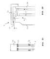
Figs. 2A and 2B show three-dimensional representations
of a display apparatus 1 according to an embodiment of
the invention. In Fig. 2A an inside view is provided, whereas
Fig. 2B shows an external view of an assembled display apparatus
1. Features identical or similar to that of Fig. 1 are
assigned identical reference numbers.
-
Figs. 2A and 2B show the LCD panel 2 that is slid out
of the support housing 3. As an indication of the dimensions
of the display apparatus 1, the height of the support housing
3, including the wheels 10, is approximately 60 centimetres,
while the depth is 20-25 centimetres. If the flat display
panel 2 is slid out entirely of the support housing 3 the total
height of the display apparatus 1 is about 110
centimetres. The width of the display apparatus 1 is approximately
1 metre.
-
The LCD panel 2 comprises a display controller 20 and
mounting means 21 to hold the display portion 4 and the display
controller 20 in a frame 22. The frame 22 comprises a
tube or hollow shaft 23 that cooperates with the screw spindle
8 to lift the LCD panel 2 out of the support housing 3 and to
retract the LCD panel 2 into the support housing 3. Fig. 2C
shows a schematic illustration in cross-section for an embodiment
of the sliding mechanism. The screw spindle 8 cooperates
with a bolt 24 fixated in the lower part of the hollow shaft
23. Accordingly, upward and downward motion of the LCD-panel 2
can be achieved by rotating the screw spindle 8. Further a
centring structure 25 is provided to hold the screw spindle 8
in position when the LCD panel 2 is slid into the support
housing 3 and accordingly, the screw spindle penetrates the
hollow shaft 23.
-
It has been found that in the slid out position of
the LCD panel 2 a chimney effect is obtained, i.e. forced convection
of air from the inside of the support housing 3 along
the LCD panel 2, which is advantageous for cooling of the LCD
panel 2. This effect is schematically illustrated in Fig. 2D,
wherein the arrows A indicate the airflow. As the side of the
frame 22 at the support housing 3 is open, the heat generated
by the electronics in the support housing 3 provides for this
airflow. The frame 22 is constructed such that it can be attached
to the display portion 4, resulting in a space for
airflow between the display portion 4 and a glass plate 26 and
behind the display portion 4 and leaving a vent 27 for the
air. Accordingly, the air is vented at the back side of the
LCD-panel 2.
-
In Fig. 2A the support housing 3 is shown with a
metallic enclosure 31, e.g. aluminium, while in Fig. 2B the
enclosure 31 has covers 32 attached to the metallic enclosure
31. The metallic enclosure 31 comprises a rigid bottom plate
33 to support the motor 7, a motor control 9, a tuner 12 and
video card 13 and a power supply 14. The cable 16 has been
omitted for clarity purposes. Further holding members 35 are
attached to the bottom plate 33 to rotatably receive the
wheels 10. The holding members 35 may be rotatably mounted
with respect to the bottom plate 33 as well. The bottom plate
33 is attached to or is integrally formed with the side walls
of the metallic enclosure 31. The metallic nature of the enclosure
31 substantially avoids electromagnetic interference
of the electric components or modules in the support housing
33. The metallic enclosure 31 may comprise of a sheet metal
plate folded to obtain the enclosure 31. In the metallic enclosure
31, guiding rails 36 are provided to guide the LCD-panel
2 in and out of the support housing 3.
-
Also, speakers 37 and an audio amplifier 38 are provided
in the support housing 3. The speakers 37 are arranged
under a certain angle to provide an improved stereo effect.
-
The covers 32, shown in Fig. 2B, can be illustrated
and/or adjusted to the taste of the owner. E.g. a company logo
39 can be provided. The covers 32 may be transparent to enable
the display apparatus 1 to function as a lamp by one or more
light emitting elements 40 provided on the metallic enclosure
31.
-
Dependent on the height of the support housing 3
above the floor surface as provided by the wheels 10 and/or
the holding members 35, one or more auxiliary housings (not
shown) can be provided underneath the bottom plate 33 to store
additional apparatus, such as a video recorder and/or a DVD
player/recorder. Consequently, the metallic enclosure 31 may
need openings to contact this additional apparatus.
-
The support housing 3 comprises an opening for sliding
out the LCD panel 2. The opening has cleaning means, such
as sweeping means 41, adapted, in use, to clean the LCD panel
2 on sliding out. Such sweeping means 41, such as a brush or
an O-ring, at least partly surround the opening, to sweep
along the LCD panel 2, or at least the display portion 4, when
it slides out of the support housing 3 and consequently removes
dust or other dirty spots from the panel 2.
-
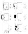
Figs. 3A-3F show several modes of operation for the
display apparatus 1 according to an embodiment of the invention.
-
Fig. 3A shows the display apparatus 1 with the LCD-panel
2 fully accommodated in the support housing 3.
-
Fig. 3B shows the display apparatus 1 with the LCD-panel
2 slid out of the support housing 3. In this mode, the
display panel may not receive television signals over the input
11. Accordingly other information can be displayed on the
LCD-panel 2, such as a clock, a preferred image such as a company
logo. Alternatively or in addition weather forecasts or
other actual information may be displayed.
-
Fig. 3C shows the display apparatus 1 with the LCD-panel
2 slid with a portion 4' of the display portion 4 out of
the support housing 3. In this mode, the display panel may not
receive television signals over the input 11. The visible portion
4' may be used to display share prices, news-feed or
other information in a ticker-tape format or mode.
-
Fig. 3D shows the display apparatus 1 with the LCD-panel
2 slid with a portion 4" of the display portion 4 out of
the support housing 3 to display image information, such as
television signals, in a first format, e.g. 4:3. The video
card 13 may allow the full image content to be displayed on
the portion 4". A black part of the display portion 4 is hidden
as this part is slid into the support housing 3.
-
Fig. 3E shows the display apparatus 1 with the LCD-panel
2 slid with the display portion 4 out of the support
housing 3 to display image information, such as television
signals, in a first format, e.g. 16:9.
-
Finally, in Fig. 3F the display apparatus 1 is shown
with both the display portion 4 and the non-display portion 5
slid out of the support housing 3. Consequently, the camera 6
is available for e.g. video conference purposes or as a web-cam.
-
It should be appreciated that the invention is not
limited to the above described embodiment, as the display apparatus
1 may e.g. comprise a second display to display other
information such as another television channel. Moreover, such
a panel may be a touch screen panel to input instructions for
the operation of the display apparatus 1 or to arrange and operate
an internet connection. The support housing 3 may also
comprise other input interfaces, such an input for a mouse and
a keyboard, either wired or wireless.
-
Fig. 4 illustrates an identification system 100 comprising
a display apparatus 1 with a display portion 4. The
display apparatus 1 may comprise a flat display panel 2 and a
support housing 3 as described above and defined in one or
more of the claims 1-16. The display apparatus 1 comprises a
memory module 101, that may be provided in the support housing
3 as an electronic module.
-
The identification system 100 further comprises a remote
control device 110 and a further identification device
120.
-
The remote control device 110 controls the display
apparatus 1 in a manner well known in the art. Accordingly,
the control device 110 comprises one or more control means
111, such as buttons, to operate the remote control device
110. A special control means is displayed as button 112, hereinafter
referred to as the identification button 112. Finally,
the remote control device 110 according to the invention has
an interface 113 to communicate with the further identification
device 120. It is noted that the remote control may be a
conventional television control, but also includes other control
means, such as a game console, a keyboard, a mobile
phone, a personal digital assistant, a watch or other means to
store and transmit an identification code.
-
The further identification device 120 comprises an
identification code, stored in a memory 121. The identification
device is typically carried by a user, wherein the
identification code stored in the memory 121 identifies the
user. The identification device may have pocket-size or
smaller dimensions. Further the identification device comprises
an interface 122 adapted to transmit the identification
code the remote control device 110 via the interface 113. It
is noted that the further identification device 120 is not a
remote control device for controlling the display apparatus 1.
-
The identification device 120 may be a chip card. In
that case the remote control device 110 comprises an opening
for insertion of the chip card to enable data transmission of
at least the identification code to the remote control device
110.
-
Alternatively the identification device 120 may be a
transponder, preferably a radio frequency identifier tag
(RFID) well known in the art. In that case the tag 120 may
wirelessly transmit the identification code to the remote control
device 110.
-
In operation according to an embodiment of the invention,
first the identification device 120 is brought by the
user in communicative connection with the remote control device
110 to enable transmission of at least data
representative of the identification code from the identification
device 120 to the remote control device 110. The identification
code identifies the identification device 120.
-
Subsequently, the user operates the identification
button 112 to identify himself at the display apparatus 1. In
this step data representing the identification code is transmitted
from the remote control device 110 to the display
apparatus 1. The memory 101 has stored the access rights for
the user to the display apparatus 1 by assigning the identification
code to these access rights. Accordingly, the user is
allowed to operate the display apparatus 1 as defined by the
access rights. These access rights may include the rights defined
in WO 98/20678.
-
It should be appreciated that the invention is not
limited to the above described embodiment for the identification
system 100, as e.g. non-allowed access can be blocked in
various ways. E.g. the display apparatus 1 may comprise a
verification module 103 that has loaded the access rights from
the memory 101 assigned to the received authorization code.
The verification module 103 may verify each instruction from
the remote control device 110 and verify whether the action
following said instruction is allowed. If not, the display apparatus
1 may simply not respond to the instruction or display
a message on the display portion 4. To access such a part appropriate
identification should first be received from the
remote control 110.