EP1576341B1 - Device for determining the blood flow in a vessel of a patient - Google Patents
Device for determining the blood flow in a vessel of a patient Download PDFInfo
- Publication number
- EP1576341B1 EP1576341B1 EP03767745A EP03767745A EP1576341B1 EP 1576341 B1 EP1576341 B1 EP 1576341B1 EP 03767745 A EP03767745 A EP 03767745A EP 03767745 A EP03767745 A EP 03767745A EP 1576341 B1 EP1576341 B1 EP 1576341B1
- Authority
- EP
- European Patent Office
- Prior art keywords
- blood
- vessel
- line
- arterial
- venous
- Prior art date
- Legal status (The legal status is an assumption and is not a legal conclusion. Google has not performed a legal analysis and makes no representation as to the accuracy of the status listed.)
- Expired - Lifetime
Links
- 230000017531 blood circulation Effects 0.000 title claims description 52
- 239000008280 blood Substances 0.000 claims description 74
- 210000004369 blood Anatomy 0.000 claims description 74
- 238000005259 measurement Methods 0.000 claims description 19
- 239000000126 substance Substances 0.000 claims description 11
- 238000001631 haemodialysis Methods 0.000 claims description 7
- 230000000322 hemodialysis Effects 0.000 claims description 7
- 238000011144 upstream manufacturing Methods 0.000 claims description 5
- 206010003226 Arteriovenous fistula Diseases 0.000 claims 2
- 238000011156 evaluation Methods 0.000 description 16
- 238000000034 method Methods 0.000 description 14
- 239000000385 dialysis solution Substances 0.000 description 12
- 206010016717 Fistula Diseases 0.000 description 7
- 230000003890 fistula Effects 0.000 description 7
- 230000002612 cardiopulmonary effect Effects 0.000 description 3
- 238000000502 dialysis Methods 0.000 description 3
- 239000012530 fluid Substances 0.000 description 3
- 238000001802 infusion Methods 0.000 description 3
- 239000007788 liquid Substances 0.000 description 3
- 239000012528 membrane Substances 0.000 description 3
- 230000003134 recirculating effect Effects 0.000 description 3
- 230000004087 circulation Effects 0.000 description 2
- 238000010790 dilution Methods 0.000 description 2
- 239000012895 dilution Substances 0.000 description 2
- 238000000746 purification Methods 0.000 description 2
- 238000000108 ultra-filtration Methods 0.000 description 2
- 208000001647 Renal Insufficiency Diseases 0.000 description 1
- 210000001367 artery Anatomy 0.000 description 1
- 210000004204 blood vessel Anatomy 0.000 description 1
- 230000001010 compromised effect Effects 0.000 description 1
- 230000001419 dependent effect Effects 0.000 description 1
- 238000001514 detection method Methods 0.000 description 1
- 238000004090 dissolution Methods 0.000 description 1
- 230000000694 effects Effects 0.000 description 1
- 238000000338 in vitro Methods 0.000 description 1
- 239000007924 injection Substances 0.000 description 1
- 238000002347 injection Methods 0.000 description 1
- 210000003734 kidney Anatomy 0.000 description 1
- 201000006370 kidney failure Diseases 0.000 description 1
- 230000003907 kidney function Effects 0.000 description 1
- 230000002045 lasting effect Effects 0.000 description 1
- 230000002503 metabolic effect Effects 0.000 description 1
- 230000000704 physical effect Effects 0.000 description 1
- 238000005070 sampling Methods 0.000 description 1
- 239000000243 solution Substances 0.000 description 1
- 238000006467 substitution reaction Methods 0.000 description 1
- 230000002123 temporal effect Effects 0.000 description 1
- 210000003462 vein Anatomy 0.000 description 1
Images

Classifications
-
- A—HUMAN NECESSITIES
- A61—MEDICAL OR VETERINARY SCIENCE; HYGIENE
- A61M—DEVICES FOR INTRODUCING MEDIA INTO, OR ONTO, THE BODY; DEVICES FOR TRANSDUCING BODY MEDIA OR FOR TAKING MEDIA FROM THE BODY; DEVICES FOR PRODUCING OR ENDING SLEEP OR STUPOR
- A61M1/00—Suction or pumping devices for medical purposes; Devices for carrying-off, for treatment of, or for carrying-over, body-liquids; Drainage systems
- A61M1/36—Other treatment of blood in a by-pass of the natural circulatory system, e.g. temperature adaptation, irradiation ; Extra-corporeal blood circuits
- A61M1/3621—Extra-corporeal blood circuits
- A61M1/3663—Flow rate transducers; Flow integrators
-
- G—PHYSICS
- G01—MEASURING; TESTING
- G01F—MEASURING VOLUME, VOLUME FLOW, MASS FLOW OR LIQUID LEVEL; METERING BY VOLUME
- G01F1/00—Measuring the volume flow or mass flow of fluid or fluent solid material wherein the fluid passes through a meter in a continuous flow
- G01F1/704—Measuring the volume flow or mass flow of fluid or fluent solid material wherein the fluid passes through a meter in a continuous flow using marked regions or existing inhomogeneities within the fluid stream, e.g. statistically occurring variations in a fluid parameter
Definitions
- the invention relates to the field of measuring methods for determining the blood flow in a blood-carrying line.
- hemodialysis treatment is one way to replace the lack of kidney function.
- the patient is drawn from blood via an arterial blood line, purified in a blood treatment element, and returned to the patient via venous blood line.
- the blood treatment element can be embodied as a hemodialyzer, in which the blood passes through a first chamber of two chambers separated from one another by a semipermeable membrane, while the second chamber is traversed by dialysis fluid. By influencing the pressure conditions in the dialyzer, blood can be withdrawn from the blood in a targeted manner.
- the blood treatment element is designed as a hemofilter. In this case, only the liquid is withdrawn from the blood through the membrane, without the liquid flowing through the second chamber. The majority of the withdrawn amount of liquid is returned to the patient via a supply of substitution fluid.
- Such methods of treatment require sufficient blood flow of about 200 to 450 ml / min. To effect sufficient purification of the blood within the several hours of treatment, which is performed about three times a week. For this reason, hemodialysis patients are generally placed with an arterial-venous fistula or shunt between an artery and a vein. A sufficient blood flow is formed in this vessel, while at the same time the vessel assumes enlarged proportions with respect to the other blood vessels, which is advantageous for puncturing.
- the blood flow in such a vessel may vary over time.
- constrictions can lead to a slow blockage of the vessel. If the blood flow falls below the required blood flow rate in the extracorporeal circuit, the blood purification performance of the treatment is compromised. In most cases, the narrowing of the vessel in this case has already progressed too far, so that it can only be filled with appropriate, e.g. surgical effort can be corrected. It is therefore desirable to learn more about such an approaching complication earlier, thereby providing other techniques for remedying it.
- a constant infusion rate indicator is infused into a vessel by means of an infusion pump, with samples taken downstream of the vessel (Kaye et al., Clinical Nephrology 8, 533 (1977)). From the evaluation of the dilution values, the fistula flow is concluded.
- This method requires an additional infusion and sampling device as well as the targeted use of an indicator.
- the US 5,830,365 describes in addition to the determination of the cardiopulmonary recirculation also a way to determine by means of Rezirkulations horren the fistula flow. In this case, however, specifically targeted bolus changes in blood properties are effected and evaluated for recirculation measurement.
- the US 4,894,164 describes a method and a device with which the heat balance of a patient during an extracorporeal blood treatment can be detected and influenced. A determination of the fistula flow is not provided.
- the invention is therefore based on the object to provide a device for determining the blood flow in a blood-carrying line, which can be applied without additional targeted or controlled actions on the blood properties.
- the invention finds application in determining the blood flow in a patient's vessel.
- the application is especially suitable whenever appropriate blood lines are present in the context of extracorporeal blood treatment anyway.
- the evaluation can then be implemented by utilizing already existing components essentially by specifying the software.
- the method described may equally be common to blood lines, even if they extend outside the human body - e.g. in in vitro applications - are used.
- dialysis fluid is conveyed by means of a delivery device 11 from a dialysis fluid source 7 via a dialysis fluid supply line 8, the dialysis fluid chamber 5 of a dialyzer 3 and via dialysis fluid discharge line 9 to a drain 10.
- blood is withdrawn from a blood-bearing conduit 40 at a first location via an arterial access 12.
- This access is followed by an arterial line 14, to which an arterial temperature sensor 20 is applied and into which a blood pump 16 is connected.
- the arterial line 14 leads into the blood chamber 6 of the dialyzer 3.
- the blood is returned via a venous line 15 via a venous access 13 of the blood-carrying line 40 at a second location.
- a venous temperature sensor 22 At the venous line 15 is a venous temperature sensor 22 at.
- the blood chamber 3 and the dialysis fluid chamber 5 are separated from one another by a semipermeable membrane 4.
- the device further comprises an evaluation unit 27, which is connected via measuring lines 23 and 24 to the arterial sensor 20 and the venous sensor 22 for detecting the respective temperatures.
- the evaluation unit 27 is further connected via a line 30 to a control unit 18 for controlling the blood pump 16 via a line 17. Via the control unit 18, the blood pump 16 can be given a conveying speed, which is simultaneously transmitted to the evaluation unit 27 via the line 30.
- the evaluation unit 27 is connected via a line 29 to a display device 28, on which the measurement and control data and evaluation results can be displayed.
- the invention is based on the observation that in order to determine the line flow Q F in the line 40, no specific manipulation of the blood properties, for example in the venous line 15, is required. Rather, it is sufficient to determine the net rate dX / dt delivered from the line 40 via the arterial line 14 and via the venous line 15 of a size X derived from a physico-chemical quantity Y of the blood.
- the net rate dX / dt which is determined from the difference between the arterial rate dX A / dt and the venous rate dX V / dt, can be determined in the case of sufficient temporal constancy during a measurement interval with the aid of the values Y A and Y V chemical property Y in the arterial and venous line.
- the net rate dX / dt can then be used to derive the plinsflußes Q F.
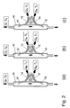
- FIGS. 2a and 2b the branch 12 of the arterial line 14 is upstream of the branch 13 of the venous line 15.
- FIG. 2a concerns the case that the blood flow Q B is smaller than the flow Q F to be measured.
- there remains a flow Q F -Q B between the arterial and venous branch and there is no immediate recirculation in the conduit 40 from blood returned via the venous line 15 to the arterial conduit 14.
- the present invention is first not applicable.
- the first component relates to the recirculating part and the second part of the line 40 flowing part.
- the recirculation factor R indicates the percentage of recirculation flow in the blood flow Q B.
- Equation (5a) is corresponding equation (5b) with corresponding indices:
- the method can be achieved by the embodiment in FIG. 1 In a dialysis treatment during a measuring time interval of a few seconds to a few minutes it can be assumed that the temperatures of the blood in the lines 14, 15 and 40 are sufficiently constant stay.
- the evaluation device 27 stores the temperatures T A determined in the arterial line 14 and T V in the venous line 15 during the measuring time interval with the sensors 20 and 22.
- the sensors 20 and 22 are as close as possible to the branches 12 and 13 arranged. Due to the distance traveled by the blood from the arterial sensor 20 to the venous sensor 22 - in particular via the dialyzer 3 - has surprisingly been found that the Temparturen T A and T V are practically always inherently sufficiently different in the application, to a measurement to enable.
- the blood flow value Q B is reported to the evaluation unit. This has been chosen sufficiently high by the control unit 18, so that the case according to FIG. 2b entry.
- the control unit sets the Blood flow to a value Q B2 ⁇ Q B , for which the case applies, which in FIG. 2a is shown.
- Q B2 150 ml / min would be suitable.
- the evaluation unit 27 detects the temperature value T A for the blood flow Q B2 .
- This value which is likewise stored by the evaluation unit 27, corresponds to the temperature value T B in equation (5a).
- all quantities in equation (5a) are known, and the evaluation unit 27 can determine the flow Q F. Possibly. it is then displayed on the display device 28 for display.
- FIG. 1 Another embodiment makes use of the situation, as in Figure 2c is shown.
- the arterial line 14 branches off the blood-carrying line 40 downstream of the venous line 15.
- This constellation is in FIG. 1 shown in parentheses.
- This can easily be done by reversing the direction of delivery of the blood pump 16. It would also be possible to swap ports 12 and 13.
- explicit reference is made to the disclosure of DE 195 28 907 C1 in which a switch circuit is presented for this case. This can be controlled manually, but also automatically by the control unit 18.
- the measured variable Y B can also be determined analogously, the connections according to the FIG. 2a must be made. This can be done manually or controlled by the control unit 18 by reversing the conveying direction of the blood pump 16 or by using a corresponding switch circuit.
- the correlations analogous to equations (5a) and (5b) are obtained by substituting the variables temperature T (which is still to be multiplied by the specific heat capacity c E and the density ⁇ B ) or concentration c in equation (9).
- the evaluation unit 27 calculates the flow Q F according to the equations (11a) and (11b), for which purpose the evaluation unit 27 first stores the individual measured values as in the preceding embodiment variants.
- the equation system (11 a) and (11 b) can now be further simplified under certain conditions.
- the blood flows through the blood chamber 6 of the dialyzer 3. This results in the exchange of substances and energy with the dialysis fluid in the dialysis fluid chamber 5.
- the two fluids flow through the dialyzer in the opposite direction, as is usual in hemodialysis, the dialysis fluid flow in the generally greater than the blood flow is chosen.
- the situation occurs in particular for the temperature that the blood at the outlet of the blood chamber 6 assumes the temperature of the dialysis fluid at the inlet of the dialysis fluid chamber 5.
- cardiopulmonary recirculation blood delivered from the venous line 15 to the line 40, with the properties Y v, reaches the arterial line 14, in which it is delivered directly through the patient's bloodstream recirculated without experiencing adequate metabolic or temperature balance in other parts of the body.
- this proportion is generally relatively small.
- a device in which the blood flow in a conduit can be determined with minimal effort, from which branch off an arterial and a venous line.
- the measurements can be carried out within a short time, whereby an influence on a possibly simultaneous blood treatment can be kept at a negligible level.
- a targeted addition of indicators is not required.
Landscapes
- Health & Medical Sciences (AREA)
- Vascular Medicine (AREA)
- Fluid Mechanics (AREA)
- Physics & Mathematics (AREA)
- Heart & Thoracic Surgery (AREA)
- Anesthesiology (AREA)
- Animal Behavior & Ethology (AREA)
- Engineering & Computer Science (AREA)
- General Physics & Mathematics (AREA)
- Biomedical Technology (AREA)
- Hematology (AREA)
- Life Sciences & Earth Sciences (AREA)
- Cardiology (AREA)
- General Health & Medical Sciences (AREA)
- Public Health (AREA)
- Veterinary Medicine (AREA)
- External Artificial Organs (AREA)
- Measuring Volume Flow (AREA)
- Measuring Pulse, Heart Rate, Blood Pressure Or Blood Flow (AREA)
Description
Die Erfindung betrifft das Gebiet von Meßverfahren zur Bestimmung des Blutflusses in einer blutführenden Leitung.The invention relates to the field of measuring methods for determining the blood flow in a blood-carrying line.
Bei Patienten mit Nierenversagen stellt die Hämodialysebehandlung eine Möglichkeit dar, die fehlenden Aufgaben der Niere zu ersetzen. Bei der Hämodialyse wird dem Patienten Blut über eine arterielle Blutleitung entnommen, in einem Blutbehandlungselement gereinigt und über eine venöse Blutleitung wieder zurückgegeben. Das Blutbehandlungselement kann als Hämodialysator ausgeführt sein, bei dem das Blut eine erste Kammer von zwei durch eine semipermeable Membran voneinander getrennten Kammern durchläuft, während die zweite Kammer von Dialysierflüssigkeit durchflossen wird. Durch Beeinflussung der Druckverhältnisse im Dialysator kann dem Blut gezielt Flüssigkeit entzogen werden.In patients with renal failure, hemodialysis treatment is one way to replace the lack of kidney function. In hemodialysis, the patient is drawn from blood via an arterial blood line, purified in a blood treatment element, and returned to the patient via venous blood line. The blood treatment element can be embodied as a hemodialyzer, in which the blood passes through a first chamber of two chambers separated from one another by a semipermeable membrane, while the second chamber is traversed by dialysis fluid. By influencing the pressure conditions in the dialyzer, blood can be withdrawn from the blood in a targeted manner.
Es ist auch möglich, daß das Blutbehandlungselement als Hämofilter ausgebildet ist. In diesem Fall wird dem Blut über die Membran nur Flüssigkeit entzogen, ohne daß die zweite Kammer von einer Flüssigkeit durchgängig durchströmt wird. Der überwiegende Teil der entzogenen Flüssigkeitsmenge wird dem Patienten über eine Zuführung von Substitutionsflüssigkeit wieder zurückgegeben.It is also possible that the blood treatment element is designed as a hemofilter. In this case, only the liquid is withdrawn from the blood through the membrane, without the liquid flowing through the second chamber. The majority of the withdrawn amount of liquid is returned to the patient via a supply of substitution fluid.
Derartige Behandlungsverfahren benötigen einen ausreichenden Blutfluß von ca. 200 bis 450 ml/min, um innerhalb der mehrere Stunden dauernden Behandlung, die ca. dreimal pro Woche durchgeführt wird, eine ausreichende Reinigung des Blutes zu bewirken. Aus diesem Grunde wird hämodialysepflichtigen Patienten im allgemeinen eine arteriell-venöse Fistel bzw. ein Shunt zwischen einer Arterie und einer Vene gelegt. In diesem Gefäß bildet sich ein ausreichender Blutstrom aus, während das Gefäß gleichzeitig gegenüber den anderen Blutgefässen vergrößerte Ausmaße annimmt, was vorteilhaft für die Punktierung ist.Such methods of treatment require sufficient blood flow of about 200 to 450 ml / min. To effect sufficient purification of the blood within the several hours of treatment, which is performed about three times a week. For this reason, hemodialysis patients are generally placed with an arterial-venous fistula or shunt between an artery and a vein. A sufficient blood flow is formed in this vessel, while at the same time the vessel assumes enlarged proportions with respect to the other blood vessels, which is advantageous for puncturing.
Der Blutfluß in so einem Gefäß kann mit der Zeit variieren. Insbesondere kann es durch Verengungen zu einer langsamen Verstopfung des Gefässes kommen. Falls der Blutfluß unterhalb der benötigten Blutflußrate im extrakorporalen Kreislauf fällt, wird die Blutreinigungsleistung der Behandlung beeinträchtigt. Meist ist die Verengung des Gefässes in diesem Fall bereits zu weit fortgeschritten, so daß sie nur mit entsprechendem, z.B. chirurgischem Aufwand behoben werden kann. Es ist daher wünschenswert, von einer solchen sich anbahnenden Komplikation früher zu erfahren, wodurch für deren Behebung auch andere Techniken zur Verfügung stehen.The blood flow in such a vessel may vary over time. In particular, constrictions can lead to a slow blockage of the vessel. If the blood flow falls below the required blood flow rate in the extracorporeal circuit, the blood purification performance of the treatment is compromised. In most cases, the narrowing of the vessel in this case has already progressed too far, so that it can only be filled with appropriate, e.g. surgical effort can be corrected. It is therefore desirable to learn more about such an approaching complication earlier, thereby providing other techniques for remedying it.
Es sind eine Reihe von Techniken vorgeschlagen worden, den Blutfluß in diesem Gefäß zu messen. Verfahren wie z.B. Ultraschall-Doppler-Systeme, die unabhängig oder mit einem extrakorporalen Blutkreislauf eingesetzt werden (z.B. Weitzel et al., Am. J. Kidney Dis. 38, 935 (2001)), erfordern dazu zusätzliche Geräte und sind kompliziert in der Handhabung. Des weiteren müssen die Messungen durch speziell geschultes Personal durchgeführt werden.A number of techniques have been proposed to measure the blood flow in this vessel. Methods such as ultrasonic Doppler systems used independently or with extracorporeal blood circulation (eg Weitzel et al., Am J. Kidney Dis. 38, 935 (2001)) require additional equipment and are complicated to handle , Furthermore, the measurements must be carried out by specially trained personnel.
Bei einem anderen bekannten Verfahren wird mit Hilfe einer Infusionspumpe ein Indikator mit konstanter Infusionsrate in ein Gefäß infundiert, wobei flußabwärts Proben aus dem Gefäß genommen werden (Kaye et al., Clinical Nephrology 8, 533 (1977)). Aus der Auswertung der Verdünnungswerte wird auf den Fistelfluß geschlossen. Diese Methode erfordert eine zusätzliche Infusions- sowie Probennahmeeinrichtung sowie den gezielten Einsatz eines Indikators.In another known method, a constant infusion rate indicator is infused into a vessel by means of an infusion pump, with samples taken downstream of the vessel (Kaye et al., Clinical Nephrology 8, 533 (1977)). From the evaluation of the dilution values, the fistula flow is concluded. This method requires an additional infusion and sampling device as well as the targeted use of an indicator.
Andere Systeme nutzen den extrakorporalen Blutkreislauf des Hämodialysegerätes zur Fistelflußmessung. Die
Nach der Lehre der
Auch anderen Verfahren wie in der
Die
Die
Der Erfindung liegt daher die Aufgabe zugrunde, eine Vorrichtung zur Bestimmung des Blutflusses in einer blutführenden Leitung bereitzustellen, die auch ohne zusätzliche gezielte bzw. gesteuerte Einwirkungen auf die Bluteigenschaften angewendet werden kann.The invention is therefore based on the object to provide a device for determining the blood flow in a blood-carrying line, which can be applied without additional targeted or controlled actions on the blood properties.
Nach der Lehre der Erfindung wird diese Aufgabe durch eine Vorrichtung mit den Merkmalen der Ansprüche 1 und 2 gelöst. Vorteilhafte Ausgestaltungen der Erfindung sind Gegenstand der Unteransprüche.According to the teachings of the invention, this object is achieved by a device having the features of
Die Erfindung findet Anwendung, um den Blutfluß in einem Gefäß eines Patienten zu bestimmen. Hierbei bietet sich die Anwendung vor allem immer dann an, wenn entsprechende Blutleitungen im Rahmen einer extrakorporalen Blutbehandlung sowieso vorliegen. Die Auswertung kann dann unter Ausnutzung bereits vorhandener Komponenten im wesentlichen durch Spezifizierung der Software umgesetzt werden.The invention finds application in determining the blood flow in a patient's vessel. In this case, the application is especially suitable whenever appropriate blood lines are present in the context of extracorporeal blood treatment anyway. The evaluation can then be implemented by utilizing already existing components essentially by specifying the software.
Das beschrieben Verfahren kann gleichermaßen allgemein bei Blutleitungen, auch wenn sie außerhalb des menschlichen Körpers verlaufen - z.B. bei in-vitro Anwendungen - zur Anwendung kommen.The method described may equally be common to blood lines, even if they extend outside the human body - e.g. in in vitro applications - are used.
Weitere Einzelheiten und Vorteile der Erfindung werden anhand eines in den Zeichnungen dargestellten Ausführungsbeispiels der erfindungsgemäßen Vorrichtung näher beschrieben. Dabei zeigen:
-
Figur 1 eine schematische Darstellung einer Ausführungsform der erfindungsgemäßen Vorrichtung sowie -
Figur 2
-
FIG. 1 a schematic representation of an embodiment of the device according to the invention and -
FIG. 2 various case constellations for the blood flow in the blood-conducting line whose flow Q F is to be determined.
Die in
In dem Blutkreislauf 2 wird einer blutführenden Leitung 40 Blut an einer ersten Stelle über einen arteriellen Zugang 12 entnommen. An diesen Zugang schließt sich eine arterielle Leitung 14 an, an der ein arterieller Temperatursensor 20 anliegt und in die eine Blutpumpe 16 geschaltet ist. Die arterielle Leitung 14 führt in die Blutkammer 6 des Dialysators 3. Aus dieser Kammer wird das Blut über eine venöse Leitung 15 über einen venösen Zugang 13 der blutführenden Leitung 40 an einer zweiten Stelle zurückgegeben. An der venösen Leitung 15 liegt ein venöser Temperatursensor 22 an.In the
Die Blutkammer 3 und die Dialysierflüssigkeitskammer 5 sind durch eine semipermeable Membran 4 voneinander getrennt.The
Die Vorrichtung weist weiterhin eine Auswerteeinheit 27 auf, die über Meßleitungen 23 und 24 mit dem arteriellen Sensor 20 und dem venösen Sensor 22 zur Erfassung der jeweiligen Temperaturen verbunden ist. Die Auswerteeinheit 27 ist des weiteren über eine Leitung 30 mit einer Steuereinheit 18 zur Ansteuerung der Blutpumpe 16 über eine Leitung 17 verbunden. Über die Steuereinheit 18 kann der Blutpumpe 16 eine Fördergeschwindigkeit vorgegeben werden, die gleichzeitig an die Auswerteeinheit 27 über die Leitung 30 übertragen wird. Die Auswerteeinheit 27 ist über eine Leitung 29 mit einer Anzeigeeinrichtung 28 verbunden, auf der die Meß- und Steuerdaten sowie Auswertungsergebnisse dargestellt werden können.The device further comprises an
Die Erfindung basiert auf der Beobachtung, daß es zur Bestimmung des Leitungsflußes QF in der Leitung 40 keiner gezielten Manipulation der Bluteigenschaften z.B. in der venösen Leitung 15 bedarf. Es ist vielmehr ausreichend, die von der Leitung 40 über die arterielle Leitung 14 abgeführte sowie über die venöse Leitung 15 zugeführte Nettorate dX/dt einer Größe X zu bestimmen, die von einer physikalisch-chemischen Größe Y des Blutes abgeleitet ist. Die Nettorate dX/dt, die aus der Differenz der arteriellen Rate dXA/dt und der venösen Rate dXV/dt bestimmt wird, läßt sich für den Fall ausreichender zeitlicher Konstanz während eines Meßintervalls mit Hilfe der Werte YA und YV der physikalisch-chemischen Eigenschaft Y in der arteriellen und venösen Leitung berechnen. Die Nettorate dX/dt kann dann zur Ableitung des Leitungsflußes QF herangezogen werden.The invention is based on the observation that in order to determine the line flow Q F in the
Für die Nettorate dX/dt gilt in dieser Situation 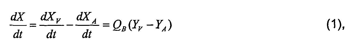
Für den zu bestimmenden Blutfluß QF und den Blutfluß QB im Blutkreislauf 2 sind verschiedene Fälle möglich, die in
Wird jedoch ein Fluß QB vorgegeben, der den Fluß QF übersteigt (![]()
![]()
Die erste Komponente betrifft den rezirkulierenden Teil und der zweite Teil den der Leitung 40 zufließenden Teil. Der Rezirkulationsfaktor R gibt dabei den prozentualen Anteil des Rezirkulationsflußes am Blutfluß QB an.The first component relates to the recirculating part and the second part of the
Der rezirkulierende Anteil liefert jedoch keinen Anteil an der Nettorate dX/dt, da er der blutführenden Leitung 40 gleichermaßen zu- und abgeführt wird. Zu dieser Nettorate dX/dt kann nur der zweite Teil einen Beitrag leisten: 

Falls Y die Wärmeenergie pro Volumen Blut und X die Wärmeenergie E des Blutes in der blutführenden Leitung 40 ist, wird aus Gleichung (4) 
Würde Y die Konzentration c eines Stoffes und X die Stoffmenge C dieses Stoffes in der blutführenden Leitung 40 sein, so lautet die Gleichung (5a) entsprechende Gleichung (5b) mit entsprechenden Indizes: 
Das Verfahren kann durch die Ausführungsform in
Von der Steuereinheit 18 wird der Blutflußwert QB an die Auswerteeinheit gemeldet. Dieser ist von der Steuereinheit 18 ausreichend hoch gewählt worden, damit der Fall gemäß
Damit die Auswerteeinheit 27 nun mit Hilfe der Gleichung (5a) den Fluß QF in der blutführenden Leitung 40 bestimmen kann, wird bei dieser Ausführungsform folgende zusätzliche Maßnahme ergriffen: Unmittelbar vor oder nach der Messung der Temperaturen TA und TV stellt die Steuereinheit den Blutfluß auf einen Wert QB2 < QB, für den der Fall zutrifft, der in
Eine andere Ausführungsvariante macht von der Situation Gebrauch, wie sie in
In Analogie zu Gleichung (2) gilt für den Fall gemäß 
In diesem Fall gilt weiter 
Wieder liefert nur der nichtrezirkulierende, zweite Anteil in Gleichung (6) einen Beitrag zur Nettorate dX/dt, die für den Fall nach
Die Gleichung (3) lautet dementsprechend 
Nach QF aufgelöst wird aus Gleichung (8) 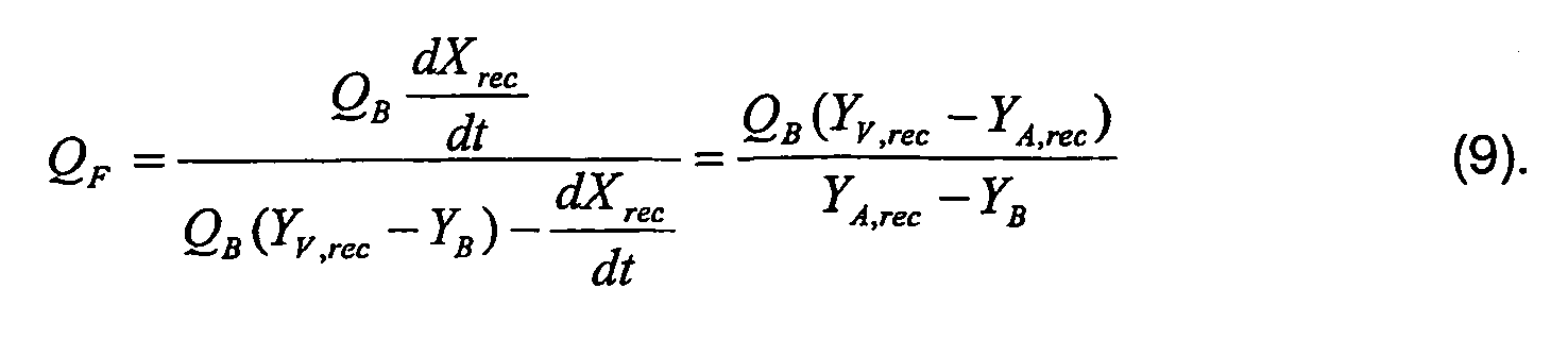
Nun kann in analoger Weise wie für den Fall nach
In einer besonders bevorzugten, dritten Ausführungsvariante wird zunächst eine erste Messung in der Konstellation nach 
Wird der Blutfluß QB so klein gewählt, daß der Fall gemäß 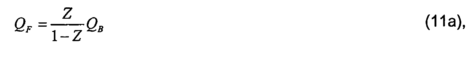

In dieser Ausführungsvariante berechnet die Auswerteeinheit 27 den Fluß QF nach den Gleichungen (11a) und (11b), wozu die Auswerteeinheit 27 die einzelnen Meßwerte wie bei den vorangegangenen Ausführungsvarianten zunächst abspeichert.In this embodiment, the
Die zu den Gleichungen (5a) und (5b) analogen Zusammenhänge ergeben sich nunmehr wiederum durch Einsetzen der Größen Temperatur T (wobei noch mit der spezifischen Wärmekapzität cE und der Dichte ρB zu multiplizieren ist) bzw. Konzentration c in Gleichung (11 b). Sollten die Messungen für dX/dt und dXrec/dt bei unterschiedlichen Blutflüssen QB und QB,rec durchgeführt werden, so kann Gleichung (11) entsprechend angepaßt werden.The correlations analogous to equations (5a) and (5b) are again given by substituting the quantities temperature T (where the heat capacity c E and the density ρ B are still to be multiplied) or the concentration c in equation (11b ). If the measurements for dX / dt and dX rec / dt are carried out at different blood flows Q B and Q B, rec , equation (11) can be adapted accordingly.
Das Gleichungssystem (11 a) und (11 b) kann nun unter bestimmten Bedingungen weiter vereinfacht werden. Bei der in
Wird nun die Temperatur in der Dialysierflüssigkeitszuführleitung 8 während der Meßphase, die Sekunden bis höchstens wenige Minuten andauert, konstant ge halten, so bleibt auch die Temperatur des Blutes in der venösen Leitung 15 konstant. Dabei haben kleinere Abweichungen der Temperatur des Blutes in der arteriellen Leitung 14 keinen Einfluß. Dies bedeutet, daß die Temperaturen TV und TV,rec in Gleichung (11 b) identisch sind. (Hierbei muß für die in 
Die nach Gleichung (1) bestimmten Nettoraten dX/dt bzw. dXrec/dt können in diesem Fall besonders einfach verwendet werden, um den Blutfluß in der blutführenden Leitung 40 zu bestimmen. Dies gilt immer dann, wenn das Kriterium Yv=Yv,rec erfüllt ist.The net rates dX / dt and dX rec / dt, respectively, determined according to equation (1), can be used particularly easily in this case in order to determine the blood flow in the blood-carrying
Die hier genannten Ausführungen sind unter der Annahme abgeleitet worden, daß der Blutfluß in der arteriellen Leitung 14 und der venösen Leitung 15 identisch ist. Bei der Hämodialyse kann es in bestimmten Fällen zu kleinen Abweichungen von dieser Annahme kommen, wenn den arteriellen bzw. venösen Leitungen Flüssigkeit durch Ultrafiltration entnommen wird. Es liegt jedoch im handwerklichen Können des Fachmanns, die Gleichungen dieser Situation anzupassen. Neben der Blutflußrate in einer der Leitung muß dann lediglich zusätzlich der Ultrafiltrationsfluß erfaßt werden.The embodiments herein have been inferred on the assumption that the blood flow in the
Ähnliches gilt im Falle der Messung an Gefäßen eines Patienten für die sogenannte kardiopulmonäre Rezirkulation. Bei der kardiopulmonären Rezirkulation gelangt von der venösen Leitung 15 an die Leitung 40 abgegebenes Blut mit den Eigenschaften Yv zur arteriellen Leitung 14, in dem es über den Blutkreislauf des Patienten direkt rezirkuliert, ohne einen ausreichenden Stoffwechsel- oder Temperaturausgleich in anderen Körperbereichen zu erfahren. Dieser Anteil ist jedoch im allgemeinen relativ klein.The same applies in the case of measurement on vessels of a patient for the so-called cardiopulmonary recirculation. In cardiopulmonary recirculation, blood delivered from the
Mit der Erfindung steht eine Vorrichtung zur Verfügung, bei der mit minimalen Aufwand der Blutfluß in einer Leitung bestimmt werden kann, von dem eine arterielle und eine venöse Leitung abzweigen. Die Messungen können innerhalb kurzer Zeit durchgeführt werden, wodurch eine Beeinflußung einer eventuell gleichzeitigen Blutbehandlung auf einem vernachlässigbaren Niveau gehalten werden kann. Eine gezielte Zugabe von Indikatoren ist nicht erforderlich.With the invention, a device is available in which the blood flow in a conduit can be determined with minimal effort, from which branch off an arterial and a venous line. The measurements can be carried out within a short time, whereby an influence on a possibly simultaneous blood treatment can be kept at a negligible level. A targeted addition of indicators is not required.
Claims (9)
- A device for measuring the blood flow in a patient's vessel, in particular an arteriovenous fistula and/or a shunt, having
an extracorporeal blood circulation with a dialyzer for performing an extracorporeal blood treatment, said blood circulation comprising an arterial line (14) that branches off from the vessel (40), and carries the blood away from the vessel and leads into a blood chamber of the dialyzer, and comprising a venous line (15) which opens into the vessel (40) and returns the blood from the blood chamber back to the vessel,
arterial measuring means (20) and venous measuring means (22) for determining a physicochemical variable Y of the blood having the value YA in the arterial line (14) and having the value YV in the venous line (15), said variable being constant over time for a measurement interval,
an analysis unit (27), which is connected to the arterial measuring means (20) and to the venous measuring means (22) and is suitable for determining the net rate dX/dt of a variable X, derived from the physicochemical variable Y, into and/or out of the vessel (40) during the measurement interval as the difference between the rate dXA/dt withdrawn through the arterial line (14) and the rate dXV/dt supplied through the venous line (15), from the values YA and YV, without any additional controlled influences on the blood properties and using the net rate dX/dt to determine the blood flow QF,
wherein means (18) are provided, which detect or determine the blood flow QB in the arterial line (14) and in the venous line (15),
wherein the physicochemical variable Y is the thermal energy per unit of volume of blood, and the variable X derived from the former is the thermal energy E of the blood in the vessel (40),
and wherein to determine the net thermal energy rate dE/dt, the measuring means (20, 22) in the arterial line (TA) and the venous line (TV) comprise temperature sensors, and the analysis unit (27) is suitable for determining the net thermal energy rate, on the basis of the equation
where CE is the specific thermal capacity and ρB is the density of the blood. - A device for measuring the blood flow in a patient's vessel, in particular an arteriovenous fistula and/or a shunt, having
an extracorporeal blood circulation with a dialyzer for performing an extracorporeal blood treatment, said blood circulation comprising an arterial line (14) that branches off from the vessel (40) and carries the blood away from the vessel and leads into a blood chamber of the dialyzer, and comprising a venous line (15) which opens into the vessel (40) and returns the blood from the blood chamber back to the vessel,
arterial measuring means (20) and venous measuring means (22) for determining a physicochemical variable Y of the blood having the value YA in the arterial line (14) and having the value YV in the venous line (15), said variable being constant over time for a measurement interval,
an analysis unit (27), which is connected to the arterial measuring means (20) and to the venous measuring means (22) and is suitable for determining the net rate dX/dt of a variable X, derived from the physicochemical variable Y, into and/or out of the vessel (40) during the measurement interval as the difference between the rate dXA/dt withdrawn through the arterial line (14) and the rate dXV/dt supplied through the venous line (15), from the values YA and YV without any additional controlled influences on the blood properties and using the net rate dX/dt to determine the blood flow QF,
wherein means (18) are provided, which detect or determine the blood flow QB in the arterial line (14) and in the venous line (15),
wherein the physicochemical variable Y is the concentration c of a substance in the blood, and X is the quantity C of this substance in the vessel (40),
and wherein to determine the net substance quantity rate dC/dt, the measuring means (20, 22) in the arterial line cA and in the venous line cV are concentration sensors, and the analysis unit (27) is suitable for determining the net substance quantity rate on the basis of the equation
- The device according to Claim 1 or 2, characterized in that the means for detecting the blood flow QB consist of a flow sensor connected to the analysis unit (27).
- The device according to Claim 3, characterized in that the means for detecting the blood flow QB consist of a control unit (18), which is provided for determining a delivery rate of a blood pump (16), which is arranged in the arterial line (14) and/or in the venous line (15) and is connected to the analysis unit (27).
- The device according to any one of the preceding claims, characterized in that the arterial line (14) branches off from the vessel (40) upstream from the venous line (15), and the analysis unit (27) is suitable for performing the determination of the blood flow QF on the basis of the equation:

where YB is the physicochemical variable in the vessel (40) upstream from the branch (12) in the arterial line (14). - The device according to any one of the preceding claims, characterized in that the arterial line (14) branches off from the vessel (40) downstream from the venous line (15),
wherein the net rate dXrec/dt and the physicochemical variable in the venous line are referred to as YV,rec and the analysis unit (27) is suitable for performing the determination of the blood flow QF on the basis of the equation:
wherein YB is the physicochemical variable in the vessel (40) upstream from the branch (13) in the venous line (15). - The device according to any one of the preceding claims, characterized in that the analysis unit (27) is suitable for determining both the net rate dX/dt in the case of an upstream branch in the arterial line (14) with respect to the venous line (15) from the vessel (40) as well as the net rate dXrec/dt in the downstream branch of the arterial line (14) with respect to the venous line (15) from the vessel (40) at the same blood flow QB and from this to determine the blood flow QF according to the following equation:

- The device according to any one of the preceding claims, characterized in that the extracorporeal blood circulation is part of a hemodialysis machine.
- The device according to any one of the preceding claims, characterized in that the device has a display unit (28) suitable for displaying the blood flow QF.
Applications Claiming Priority (3)
| Application Number | Priority Date | Filing Date | Title |
|---|---|---|---|
| DE10259437 | 2002-12-19 | ||
| DE10259437A DE10259437B3 (en) | 2002-12-19 | 2002-12-19 | Method and device for determining blood flow in a blood-carrying line |
| PCT/EP2003/013730 WO2004057279A1 (en) | 2002-12-19 | 2003-12-04 | Method and device for determining the blood flow in a blood-conducting tube |
Publications (2)
| Publication Number | Publication Date |
|---|---|
| EP1576341A1 EP1576341A1 (en) | 2005-09-21 |
| EP1576341B1 true EP1576341B1 (en) | 2013-02-20 |
Family
ID=32667511
Family Applications (1)
| Application Number | Title | Priority Date | Filing Date |
|---|---|---|---|
| EP03767745A Expired - Lifetime EP1576341B1 (en) | 2002-12-19 | 2003-12-04 | Device for determining the blood flow in a vessel of a patient |
Country Status (8)
| Country | Link |
|---|---|
| US (1) | US7704213B2 (en) |
| EP (1) | EP1576341B1 (en) |
| JP (1) | JP4480586B2 (en) |
| CN (1) | CN100419388C (en) |
| AU (1) | AU2003292190A1 (en) |
| DE (1) | DE10259437B3 (en) |
| ES (1) | ES2401776T3 (en) |
| WO (1) | WO2004057279A1 (en) |
Cited By (1)
| Publication number | Priority date | Publication date | Assignee | Title |
|---|---|---|---|---|
| DE102016001710A1 (en) | 2016-02-15 | 2017-08-17 | Fresenius Medical Care Deutschland Gmbh | Device for extracorporeal blood treatment with an evaluation and control unit |
Families Citing this family (17)
| Publication number | Priority date | Publication date | Assignee | Title |
|---|---|---|---|---|
| AU2006230176B2 (en) | 2005-03-29 | 2012-04-05 | Martin Roche | Body parameter detecting sensor and method for detecting body parameters |
| US11457813B2 (en) | 2005-03-29 | 2022-10-04 | Martin W. Roche | Method for detecting body parameters |
| JP4925159B2 (en) * | 2005-10-12 | 2012-04-25 | 日機装株式会社 | Blood purification equipment |
| DE102006011346A1 (en) * | 2006-03-11 | 2007-09-13 | Fresenius Medical Care Deutschland Gmbh | Method and device for operating an electric peristaltic peristaltic pump |
| US7815588B2 (en) * | 2006-06-07 | 2010-10-19 | Paul Sakiewicz | Method and device for reversing lines in the procedure of hemodialysis |
| JP4573860B2 (en) * | 2007-08-22 | 2010-11-04 | 日機装株式会社 | Blood purification equipment |
| DE102007056475A1 (en) * | 2007-11-22 | 2009-06-04 | Fresenius Medical Care Deutschland Gmbh | A method and apparatus for determining recirculation in a fistula or cardiopulmonary recirculation, and a blood treatment apparatus having means for determining fistula recirculation or cardiopulmonary recirculation percentage |
| DE102008003714A1 (en) | 2008-01-09 | 2009-07-16 | Fresenius Medical Care Deutschland Gmbh | A method of determining the rate of recirculation in a fistula and / or cardiopulmonary recirculation on the sum of fistula recirculation and cardiopulmonary recirculation |
| DE102013011010A1 (en) * | 2013-07-02 | 2015-01-22 | Fresenius Medical Care Deutschland Gmbh | Method and apparatus for turbulence generation by pulsating flow |
| EP3103495B1 (en) * | 2015-06-10 | 2018-08-29 | B. Braun Avitum AG | Solution circuit apparatus with bypass, and blood purification system comprising the solution circuit apparatus |
| US10668206B2 (en) * | 2015-10-09 | 2020-06-02 | Nxstage Medical, Inc. | Body temperature measurement devices, methods, and systems |
| DE102015016854A1 (en) * | 2015-12-23 | 2017-06-29 | Fresenius Medical Care Deutschland Gmbh | Dialysis machine with means for detecting a shunt recirculation |
| CN109475303A (en) * | 2016-07-14 | 2019-03-15 | 皇家飞利浦有限公司 | The devices, systems, and methods fed back for the quality to the property measurement results in blood vessel |
| DE102016008821A1 (en) * | 2016-07-19 | 2018-01-25 | Fresenius Medical Care Deutschland Gmbh | Dialysis machine and method for correcting the blood flow value |
| JP7061114B6 (en) * | 2016-09-28 | 2022-06-03 | コーニンクレッカ フィリップス エヌ ヴェ | Blood flow measurement system |
| JP7038358B2 (en) * | 2017-09-14 | 2022-03-18 | 株式会社アルチザンラボ | Blood purification device |
| CN109171680B (en) * | 2018-03-27 | 2021-04-13 | 清华-伯克利深圳学院筹备办公室 | Sensor capable of measuring flow of side branch blood vessel of cardiac artery |
Family Cites Families (13)
| Publication number | Priority date | Publication date | Assignee | Title |
|---|---|---|---|---|
| FR1452215A (en) * | 1965-07-28 | 1966-09-09 | Philips Massiot Mat Medic | Device for measuring the flow rate of a fluid |
| DE3636995A1 (en) * | 1986-10-30 | 1988-05-11 | Fresenius Ag | METHOD AND DEVICE FOR EXTRACTING HEAT FROM BLOOD IN THE EXTRACORPORAL CIRCUIT |
| US5685989A (en) | 1994-09-16 | 1997-11-11 | Transonic Systems, Inc. | Method and apparatus to measure blood flow and recirculation in hemodialysis shunts |
| DE19528907C1 (en) | 1995-08-05 | 1996-11-07 | Fresenius Ag | Haemodynamic parameter measurement equipment for extracorporeal blood circulation appts. |
| DE19541783C1 (en) | 1995-11-09 | 1997-03-27 | Fresenius Ag | Method for operating a blood treatment device for determining hemodynamic parameters during an extracorporeal blood treatment and device for determining hemodynamic parameters during an extracorporeal blood treatment |
| CA2268519A1 (en) | 1996-10-23 | 1998-04-30 | In-Line Diagnostics Corporation | System and method for noninvasive hemodynamic measurements in hemodialysis shunts |
| US6189388B1 (en) | 1997-11-12 | 2001-02-20 | Gambro, Inc. | Access flow monitoring using reversal of normal blood flow |
| US6648845B1 (en) | 1998-01-07 | 2003-11-18 | Fresenius Medical Care North America | Method and apparatus for determining hemodialysis parameters |
| WO2000024440A1 (en) * | 1998-10-23 | 2000-05-04 | Gambro Ab | Method and device for measuring access flow |
| DE19917196C2 (en) | 1999-04-16 | 2002-04-04 | Motorola Inc | Method for transmitting the speaking time available on an answering machine of a called radio device and radio device with an answering machine |
| DE19917197C1 (en) | 1999-04-16 | 2000-07-27 | Fresenius Medical Care De Gmbh | Method to determine blood flow in vessel entrance of haemodialysis unit; involves measuring arterial and venous pressures when vessel entrance is open to allow blood flow and closed to prevent blood flow |
| US6868739B1 (en) * | 1999-10-19 | 2005-03-22 | Transonic Systems, Inc. | Method and apparatus to measure blood flow by an introduced volume change |
| US6746407B2 (en) | 2000-12-29 | 2004-06-08 | Hema Metrics, Inc. | Method of measuring transcutaneous access blood flow |
-
2002
- 2002-12-19 DE DE10259437A patent/DE10259437B3/en not_active Expired - Fee Related
-
2003
- 2003-12-04 WO PCT/EP2003/013730 patent/WO2004057279A1/en active Application Filing
- 2003-12-04 ES ES03767745T patent/ES2401776T3/en not_active Expired - Lifetime
- 2003-12-04 EP EP03767745A patent/EP1576341B1/en not_active Expired - Lifetime
- 2003-12-04 JP JP2004561222A patent/JP4480586B2/en not_active Expired - Fee Related
- 2003-12-04 CN CNB2003801071273A patent/CN100419388C/en not_active Expired - Fee Related
- 2003-12-04 AU AU2003292190A patent/AU2003292190A1/en not_active Abandoned
- 2003-12-04 US US10/540,110 patent/US7704213B2/en not_active Expired - Fee Related
Cited By (3)
| Publication number | Priority date | Publication date | Assignee | Title |
|---|---|---|---|---|
| DE102016001710A1 (en) | 2016-02-15 | 2017-08-17 | Fresenius Medical Care Deutschland Gmbh | Device for extracorporeal blood treatment with an evaluation and control unit |
| WO2017140424A2 (en) | 2016-02-15 | 2017-08-24 | Fresenius Medical Care Deutschland Gmbh | Equipment for extra-corporeal treatment of blood, comprising an evaluation- and control unit |
| DE102016001710B4 (en) | 2016-02-15 | 2022-08-25 | Fresenius Medical Care Deutschland Gmbh | Device for extracorporeal blood treatment with an evaluation and control unit |
Also Published As
| Publication number | Publication date |
|---|---|
| US20060064025A1 (en) | 2006-03-23 |
| JP2006510421A (en) | 2006-03-30 |
| DE10259437B3 (en) | 2004-09-16 |
| ES2401776T3 (en) | 2013-04-24 |
| JP4480586B2 (en) | 2010-06-16 |
| EP1576341A1 (en) | 2005-09-21 |
| AU2003292190A1 (en) | 2004-07-14 |
| CN100419388C (en) | 2008-09-17 |
| WO2004057279A1 (en) | 2004-07-08 |
| CN1729384A (en) | 2006-02-01 |
| US7704213B2 (en) | 2010-04-27 |
Similar Documents
| Publication | Publication Date | Title |
|---|---|---|
| EP1576341B1 (en) | Device for determining the blood flow in a vessel of a patient | |
| EP1197236B1 (en) | Method for evaluating the intraperitoneal volume and apparatus for peritoneal dialysis | |
| EP1615680B1 (en) | Haemodialysis device | |
| DE19528907C1 (en) | Haemodynamic parameter measurement equipment for extracorporeal blood circulation appts. | |
| EP0911043B1 (en) | Device for measuring performance parameters of substance and energy exchange modules | |
| EP0845273B1 (en) | Means for in vivo determining haemodialysis parameters | |
| EP1835950B1 (en) | Device and method for detecting complications during an extracorporeal blood treatment | |
| EP2714128B1 (en) | Device and method for recognizing an operating state of an extra-corporeal blood treatment | |
| EP2217303B1 (en) | Device for determining the recirculation in a fistula or the cardiopulmonary recirculation, and a blood treatment device comprising a device for determining the fistula recirculation or the cardiopulmonary recirculation part | |
| EP0773035B1 (en) | Method and apparatus for determining hemodynamic variables during extracorporal blood treatment | |
| EP2249898B1 (en) | Method for determining the percentage of recirculation in a fistula and/or cardiopulmonary recirculation relative to the total fistula recirculation and cardiopulmonary recirculation | |
| EP2783715B1 (en) | Method for detecting recirculation in an arteriovenous shunt during ongoing haemodialysis and dialysis system | |
| EP3034110B1 (en) | Method and device for determining the transmembrane pressure in an extracorporeal blood treatment | |
| EP1217379A2 (en) | Method for determining the ion concentration of blood and dialysis apparatus | |
| DE3640089A1 (en) | METHOD AND DEVICE FOR DETERMINING THE INTRAVASAL BLOOD VOLUME DURING HAEMODIALYSIS | |
| EP2897669A1 (en) | Device and method for detecting recirculation during an extracorporeal blood treatment | |
| DE2644062A1 (en) | Automatic regulator for haemodialysis appts. - with continuous extraction of water from patient during dialysis | |
| EP3955988B1 (en) | Recirculation measurement by means of diffusion equilibrium | |
| EP3634533B1 (en) | Device for an extracorporeal blood treatment and for determining a hemodynamic parameter during an extracorporeal blood treatment | |
| DE102020111358A1 (en) | Dialysis device with a device for determining at least two hemodialysis parameters and a method for determining at least two hemodialysis parameters | |
| DE10254988A1 (en) | Monitoring pressure in vessel entrance during extracorporal blood treatment involves computing change in pressure in vessel entrance from measured arterial or venous pressure, comparing with threshold |
Legal Events
| Date | Code | Title | Description |
|---|---|---|---|
| PUAI | Public reference made under article 153(3) epc to a published international application that has entered the european phase |
Free format text: ORIGINAL CODE: 0009012 |
|
| 17P | Request for examination filed |
Effective date: 20050719 |
|
| AK | Designated contracting states |
Kind code of ref document: A1 Designated state(s): AT BE BG CH CY CZ DE DK EE ES FI FR GB GR HU IE IT LI LU MC NL PT RO SE SI SK TR |
|
| AX | Request for extension of the european patent |
Extension state: AL LT LV MK |
|
| DAX | Request for extension of the european patent (deleted) | ||
| 17Q | First examination report despatched |
Effective date: 20071015 |
|
| GRAP | Despatch of communication of intention to grant a patent |
Free format text: ORIGINAL CODE: EPIDOSNIGR1 |
|
| GRAS | Grant fee paid |
Free format text: ORIGINAL CODE: EPIDOSNIGR3 |
|
| GRAA | (expected) grant |
Free format text: ORIGINAL CODE: 0009210 |
|
| AK | Designated contracting states |
Kind code of ref document: B1 Designated state(s): AT BE BG CH CY CZ DE DK EE ES FI FR GB GR HU IE IT LI LU MC NL PT RO SE SI SK TR |
|
| REG | Reference to a national code |
Ref country code: GB Ref legal event code: FG4D Free format text: NOT ENGLISH |
|
| REG | Reference to a national code |
Ref country code: CH Ref legal event code: EP |
|
| REG | Reference to a national code |
Ref country code: AT Ref legal event code: REF Ref document number: 597743 Country of ref document: AT Kind code of ref document: T Effective date: 20130315 |
|
| REG | Reference to a national code |
Ref country code: IE Ref legal event code: FG4D Free format text: LANGUAGE OF EP DOCUMENT: GERMAN |
|
| REG | Reference to a national code |
Ref country code: DE Ref legal event code: R096 Ref document number: 50314686 Country of ref document: DE Effective date: 20130418 |
|
| REG | Reference to a national code |
Ref country code: ES Ref legal event code: FG2A Ref document number: 2401776 Country of ref document: ES Kind code of ref document: T3 Effective date: 20130424 |
|
| REG | Reference to a national code |
Ref country code: SE Ref legal event code: TRGR |
|
| REG | Reference to a national code |
Ref country code: NL Ref legal event code: VDEP Effective date: 20130220 |
|
| PG25 | Lapsed in a contracting state [announced via postgrant information from national office to epo] |
Ref country code: BG Free format text: LAPSE BECAUSE OF FAILURE TO SUBMIT A TRANSLATION OF THE DESCRIPTION OR TO PAY THE FEE WITHIN THE PRESCRIBED TIME-LIMIT Effective date: 20130520 |
|
| PG25 | Lapsed in a contracting state [announced via postgrant information from national office to epo] |
Ref country code: PT Free format text: LAPSE BECAUSE OF FAILURE TO SUBMIT A TRANSLATION OF THE DESCRIPTION OR TO PAY THE FEE WITHIN THE PRESCRIBED TIME-LIMIT Effective date: 20130620 Ref country code: FI Free format text: LAPSE BECAUSE OF FAILURE TO SUBMIT A TRANSLATION OF THE DESCRIPTION OR TO PAY THE FEE WITHIN THE PRESCRIBED TIME-LIMIT Effective date: 20130220 Ref country code: SI Free format text: LAPSE BECAUSE OF FAILURE TO SUBMIT A TRANSLATION OF THE DESCRIPTION OR TO PAY THE FEE WITHIN THE PRESCRIBED TIME-LIMIT Effective date: 20130220 Ref country code: GR Free format text: LAPSE BECAUSE OF FAILURE TO SUBMIT A TRANSLATION OF THE DESCRIPTION OR TO PAY THE FEE WITHIN THE PRESCRIBED TIME-LIMIT Effective date: 20130521 |
|
| PG25 | Lapsed in a contracting state [announced via postgrant information from national office to epo] |
Ref country code: NL Free format text: LAPSE BECAUSE OF FAILURE TO SUBMIT A TRANSLATION OF THE DESCRIPTION OR TO PAY THE FEE WITHIN THE PRESCRIBED TIME-LIMIT Effective date: 20130220 Ref country code: EE Free format text: LAPSE BECAUSE OF FAILURE TO SUBMIT A TRANSLATION OF THE DESCRIPTION OR TO PAY THE FEE WITHIN THE PRESCRIBED TIME-LIMIT Effective date: 20130220 Ref country code: CZ Free format text: LAPSE BECAUSE OF FAILURE TO SUBMIT A TRANSLATION OF THE DESCRIPTION OR TO PAY THE FEE WITHIN THE PRESCRIBED TIME-LIMIT Effective date: 20130220 Ref country code: DK Free format text: LAPSE BECAUSE OF FAILURE TO SUBMIT A TRANSLATION OF THE DESCRIPTION OR TO PAY THE FEE WITHIN THE PRESCRIBED TIME-LIMIT Effective date: 20130220 Ref country code: SK Free format text: LAPSE BECAUSE OF FAILURE TO SUBMIT A TRANSLATION OF THE DESCRIPTION OR TO PAY THE FEE WITHIN THE PRESCRIBED TIME-LIMIT Effective date: 20130220 Ref country code: RO Free format text: LAPSE BECAUSE OF FAILURE TO SUBMIT A TRANSLATION OF THE DESCRIPTION OR TO PAY THE FEE WITHIN THE PRESCRIBED TIME-LIMIT Effective date: 20130220 |
|
| PG25 | Lapsed in a contracting state [announced via postgrant information from national office to epo] |
Ref country code: CY Free format text: LAPSE BECAUSE OF FAILURE TO SUBMIT A TRANSLATION OF THE DESCRIPTION OR TO PAY THE FEE WITHIN THE PRESCRIBED TIME-LIMIT Effective date: 20130220 |
|
| PLBE | No opposition filed within time limit |
Free format text: ORIGINAL CODE: 0009261 |
|
| STAA | Information on the status of an ep patent application or granted ep patent |
Free format text: STATUS: NO OPPOSITION FILED WITHIN TIME LIMIT |
|
| 26N | No opposition filed |
Effective date: 20131121 |
|
| REG | Reference to a national code |
Ref country code: DE Ref legal event code: R097 Ref document number: 50314686 Country of ref document: DE Effective date: 20131121 |
|
| BERE | Be: lapsed |
Owner name: FRESENIUS MEDICAL CARE DEUTSCHLAND G.M.B.H. Effective date: 20131231 |
|
| REG | Reference to a national code |
Ref country code: CH Ref legal event code: PL |
|
| PG25 | Lapsed in a contracting state [announced via postgrant information from national office to epo] |
Ref country code: LU Free format text: LAPSE BECAUSE OF FAILURE TO SUBMIT A TRANSLATION OF THE DESCRIPTION OR TO PAY THE FEE WITHIN THE PRESCRIBED TIME-LIMIT Effective date: 20131204 Ref country code: MC Free format text: LAPSE BECAUSE OF FAILURE TO SUBMIT A TRANSLATION OF THE DESCRIPTION OR TO PAY THE FEE WITHIN THE PRESCRIBED TIME-LIMIT Effective date: 20130220 |
|
| REG | Reference to a national code |
Ref country code: IE Ref legal event code: MM4A |
|
| PG25 | Lapsed in a contracting state [announced via postgrant information from national office to epo] |
Ref country code: LI Free format text: LAPSE BECAUSE OF NON-PAYMENT OF DUE FEES Effective date: 20131231 Ref country code: CH Free format text: LAPSE BECAUSE OF NON-PAYMENT OF DUE FEES Effective date: 20131231 Ref country code: BE Free format text: LAPSE BECAUSE OF NON-PAYMENT OF DUE FEES Effective date: 20131231 Ref country code: IE Free format text: LAPSE BECAUSE OF NON-PAYMENT OF DUE FEES Effective date: 20131204 |
|
| REG | Reference to a national code |
Ref country code: AT Ref legal event code: MM01 Ref document number: 597743 Country of ref document: AT Kind code of ref document: T Effective date: 20131204 |
|
| PG25 | Lapsed in a contracting state [announced via postgrant information from national office to epo] |
Ref country code: AT Free format text: LAPSE BECAUSE OF NON-PAYMENT OF DUE FEES Effective date: 20131204 |
|
| PG25 | Lapsed in a contracting state [announced via postgrant information from national office to epo] |
Ref country code: HU Free format text: LAPSE BECAUSE OF FAILURE TO SUBMIT A TRANSLATION OF THE DESCRIPTION OR TO PAY THE FEE WITHIN THE PRESCRIBED TIME-LIMIT; INVALID AB INITIO Effective date: 20031204 |
|
| REG | Reference to a national code |
Ref country code: FR Ref legal event code: PLFP Year of fee payment: 13 |
|
| REG | Reference to a national code |
Ref country code: FR Ref legal event code: PLFP Year of fee payment: 14 |
|
| REG | Reference to a national code |
Ref country code: FR Ref legal event code: PLFP Year of fee payment: 15 |
|
| PGFP | Annual fee paid to national office [announced via postgrant information from national office to epo] |
Ref country code: TR Payment date: 20171123 Year of fee payment: 15 Ref country code: FR Payment date: 20171121 Year of fee payment: 15 |
|
| PGFP | Annual fee paid to national office [announced via postgrant information from national office to epo] |
Ref country code: SE Payment date: 20171123 Year of fee payment: 15 Ref country code: GB Payment date: 20171121 Year of fee payment: 15 Ref country code: IT Payment date: 20171120 Year of fee payment: 15 |
|
| PGFP | Annual fee paid to national office [announced via postgrant information from national office to epo] |
Ref country code: DE Payment date: 20171231 Year of fee payment: 15 Ref country code: ES Payment date: 20180103 Year of fee payment: 15 |
|
| REG | Reference to a national code |
Ref country code: DE Ref legal event code: R119 Ref document number: 50314686 Country of ref document: DE |
|
| REG | Reference to a national code |
Ref country code: SE Ref legal event code: EUG |
|
| PG25 | Lapsed in a contracting state [announced via postgrant information from national office to epo] |
Ref country code: SE Free format text: LAPSE BECAUSE OF NON-PAYMENT OF DUE FEES Effective date: 20181205 |
|
| GBPC | Gb: european patent ceased through non-payment of renewal fee |
Effective date: 20181204 |
|
| PG25 | Lapsed in a contracting state [announced via postgrant information from national office to epo] |
Ref country code: DE Free format text: LAPSE BECAUSE OF NON-PAYMENT OF DUE FEES Effective date: 20190702 Ref country code: IT Free format text: LAPSE BECAUSE OF NON-PAYMENT OF DUE FEES Effective date: 20181204 Ref country code: FR Free format text: LAPSE BECAUSE OF NON-PAYMENT OF DUE FEES Effective date: 20181231 |
|
| PG25 | Lapsed in a contracting state [announced via postgrant information from national office to epo] |
Ref country code: GB Free format text: LAPSE BECAUSE OF NON-PAYMENT OF DUE FEES Effective date: 20181204 |
|
| REG | Reference to a national code |
Ref country code: ES Ref legal event code: FD2A Effective date: 20200131 |
|
| PG25 | Lapsed in a contracting state [announced via postgrant information from national office to epo] |
Ref country code: ES Free format text: LAPSE BECAUSE OF NON-PAYMENT OF DUE FEES Effective date: 20181205 |
|
| PG25 | Lapsed in a contracting state [announced via postgrant information from national office to epo] |
Ref country code: TR Free format text: LAPSE BECAUSE OF NON-PAYMENT OF DUE FEES Effective date: 20181204 |