EP1573276B1 - Device for positioning a clamp-on flowmeter on a container - Google Patents
Device for positioning a clamp-on flowmeter on a container Download PDFInfo
- Publication number
- EP1573276B1 EP1573276B1 EP03789157A EP03789157A EP1573276B1 EP 1573276 B1 EP1573276 B1 EP 1573276B1 EP 03789157 A EP03789157 A EP 03789157A EP 03789157 A EP03789157 A EP 03789157A EP 1573276 B1 EP1573276 B1 EP 1573276B1
- Authority
- EP
- European Patent Office
- Prior art keywords
- unit
- per
- ultrasonic
- display unit
- container
- Prior art date
- Legal status (The legal status is an assumption and is not a legal conclusion. Google has not performed a legal analysis and makes no representation as to the accuracy of the status listed.)
- Expired - Lifetime
Links
- 230000008859 change Effects 0.000 claims abstract description 7
- 238000011156 evaluation Methods 0.000 claims abstract description 7
- 238000000034 method Methods 0.000 claims description 12
- 230000003287 optical effect Effects 0.000 claims description 7
- 230000008569 process Effects 0.000 claims description 6
- 239000011295 pitch Substances 0.000 claims description 4
- 239000003086 colorant Substances 0.000 claims 1
- 238000005259 measurement Methods 0.000 description 18
- 230000008878 coupling Effects 0.000 description 10
- 238000010168 coupling process Methods 0.000 description 10
- 238000005859 coupling reaction Methods 0.000 description 10
- 238000006073 displacement reaction Methods 0.000 description 6
- 238000002604 ultrasonography Methods 0.000 description 5
- 239000000463 material Substances 0.000 description 4
- 244000089486 Phragmites australis subsp australis Species 0.000 description 3
- 230000001419 dependent effect Effects 0.000 description 2
- 239000007788 liquid Substances 0.000 description 2
- 230000007246 mechanism Effects 0.000 description 2
- 230000008901 benefit Effects 0.000 description 1
- 238000012937 correction Methods 0.000 description 1
- 238000001514 detection method Methods 0.000 description 1
- 230000008034 disappearance Effects 0.000 description 1
- 238000005516 engineering process Methods 0.000 description 1
- 239000012535 impurity Substances 0.000 description 1
- 239000002243 precursor Substances 0.000 description 1
- 238000012545 processing Methods 0.000 description 1
- 230000007704 transition Effects 0.000 description 1
- 230000000007 visual effect Effects 0.000 description 1
Images
Classifications
-
- G—PHYSICS
- G01—MEASURING; TESTING
- G01F—MEASURING VOLUME, VOLUME FLOW, MASS FLOW OR LIQUID LEVEL; METERING BY VOLUME
- G01F1/00—Measuring the volume flow or mass flow of fluid or fluent solid material wherein the fluid passes through a meter in a continuous flow
- G01F1/66—Measuring the volume flow or mass flow of fluid or fluent solid material wherein the fluid passes through a meter in a continuous flow by measuring frequency, phase shift or propagation time of electromagnetic or other waves, e.g. using ultrasonic flowmeters
- G01F1/667—Arrangements of transducers for ultrasonic flowmeters; Circuits for operating ultrasonic flowmeters
-
- G—PHYSICS
- G01—MEASURING; TESTING
- G01F—MEASURING VOLUME, VOLUME FLOW, MASS FLOW OR LIQUID LEVEL; METERING BY VOLUME
- G01F25/00—Testing or calibration of apparatus for measuring volume, volume flow or liquid level or for metering by volume
- G01F25/10—Testing or calibration of apparatus for measuring volume, volume flow or liquid level or for metering by volume of flowmeters
Definitions
- the invention relates to a device for postioning a clamp-on flowmeter on a container which is flowed through by a medium.
- Clamp-on ultrasonic flowmeters are widely used in process and automation technology. They make it possible to determine the volume and / or mass flow of a medium in a container, in particular in a pipeline without contact. Furthermore, you have the advantage that they can be attached to the outside of the pipeline. Clamp-on ultrasonic flowmeters are for example in the EP 0 686 255 B1 , of the U.S. Patent 4,484,478 or the U.S. Patent 4,598,593 described.
- the known ultrasonic flowmeters operate either on the Doppler principle or on the transit time difference principle.
- running time difference principle the different duration of ultrasonic measuring signals in the flow direction and against the flow direction of the medium is evaluated.
- the ultrasonic measuring signals are alternately transmitted or received by the ultrasonic transducers in the flow direction and counter to the flow direction of the medium. Based on the transit time difference of the ultrasonic measuring signals, the flow rate and thus at a known diameter of the tube of the volume flow or at a known density of the medium mass flow can be determined.
- ultrasonic measurement signals are coupled into the flowing medium at a predetermined frequency.
- the reflected in the medium ultrasonic measurement signals are evaluated.
- On the basis of an occurring between the coupled and the reflected ultrasonic measurement signal frequency shift can also be the flow rate determine the medium or the volume and / or mass flow.
- the use of flow meters, which operate on the Doppler principle is only possible if in the medium air bubbles or impurities are present at which the ultrasonic measurement signals are reflected.
- the use of such ultrasonic flowmeters compared to the ultrasonic flowmeters, which operate on the transit time difference principle, rather limited.
- the ultrasonic measurement signals are irradiated at a predetermined angle in the container in which the medium is located.
- the two ultrasonic transducers In order that the largest possible proportion of the energy radiated into the container by an ultrasonic transducer is received in the other ultrasonic transducer, the two ultrasonic transducers must have a defined distance from one another. The respective position of the ultrasonic transducer on the container is dependent on the inner diameter of the pipeline and on the speed of sound of the medium. Other application parameters to which a relatively large error sometimes adheres include the wall thickness of the pipeline and the speed of sound of the material of the pipeline.
- An ultrasonic transducer used in a clamp-on flowmeter has at least one piezoelectric element generating the ultrasonic measurement signals and a coupling wedge.
- the coupling wedge is usually made of plastic and serves on the one hand to irradiate the ultrasonic signals at a defined angle into the tube and on the other hand the impedance matching.
- the ultrasonic measuring signals generated in a piezoelectric element are via the coupling wedge or the flow body and the pipe wall in the liquid medium directed. Because the speed of sound in a liquid and in plastic are different from each other, the ultrasonic waves are refracted in the transition from one medium to the other.
- the angle of refraction itself is determined by Snell's law, ie the angle of refraction depends on the ratio of the propagation velocities of the two media.
- Snell's law ie the angle of refraction depends on the ratio of the propagation velocities of the two media.
- the speed of sound of plastic shows a relatively strong temperature dependence.
- the speed of sound of plastic changes from about 2500 m / s at 25 ° C to about 2200 m / s at 130 ° C.
- the propagation direction of the ultrasonic measuring signals in the flowing medium In addition to the change in the transit time of the ultrasonic measuring signals in the plastic of the coupling wedge caused by the temperature changes also the propagation direction of the ultrasonic measuring signals in the flowing medium.
- the invention has for its object to propose a device with which the positioning of a clamp-on flowmeter is simplified to a container.
- the object is achieved in that two ultrasonic transducers are provided which emit measurement signals in the container and / or receive from the container; Furthermore, a positioning unit for the variable positioning of the ultrasonic transducers on the container and a control / evaluation unit are provided, wherein the control / evaluation of predetermined process and / or system sizes calculates a characteristic target size of the measured signals and based on a comparison of the calculated target Size with the corresponding measured actual size determines whether the ultrasonic transducers are optimally positioned or whether the position of the ultrasonic transducers is to be changed.
- a display unit is used, which brings a required change in position and / or the direction in which a position change has to be made to display.
- a detection of a malpositioning of the ultrasound transducers and a countermeasure compensating for this mispositioning takes place on the basis of the signals received in each case by an ultrasound transducer. On the basis of the received measurement signals is at least determines a occurring under the application conditions characteristic actual size of the measured signal.
- the characteristic value is preferably the intensity of the measurement signals and / or the transit time of the measurement signals. This measured value is compared with a corresponding characteristic target size. If the characteristic quantity is the transit time, the corresponding target size is calculated using the law of refraction of Snellius for the purpose of calculation. Usually, not all quantities mentioned in the corresponding equations are exactly known. Thus, in many cases, the exact speed of sound of the medium is not known. In such a case, the e.g. using a table, most likely value for the speed of sound of the medium used. Alternatively, it is possible to determine the sound velocity of the medium by means of a measurement by measuring the transit time of ultrasonic waves in the direction perpendicular to the flow direction of the medium. Such methods are already used in practice, so that can be dispensed with an exact description at this point.
- the display unit is configured such that it signals to the operator the correct position of the ultrasonic transducer on optical and / or acoustically or that the display unit, if necessary, gives the operators successive hints in which direction at least one of the ultrasonic transducers to postpone for correct positioning.
- the display unit is an integral part of the clamp-on Druchflußmeßtechniks.
- the display unit is a display.
- the information to the user can be effected, for example, by indicating the direction of displacement and / or the amount of displacement of the two ultrasonic transducers on the display unit in numerical and / or graphic symbols.
- the display unit may be at least one optical and / or at least one acoustic reproduction element, the element used in each case being operable in different modes.
- the optical display element may be a light-emitting diode, with the modes in this case being e.g. is a flashing mode, an on mode and / or an off mode.
- the optical reproduction element is designed such that different color codes and / or symbols are assigned to the different modes.
- an acoustic reproduction element is used, then it is preferably designed such that the different modes are realized by different pitches and / or by different repetition frequencies of at least one pitch.
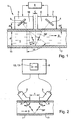
- Fig. 1 shows a schematic representation of the sound path SP of a Ultraschallmeßsignals in a pipe or in a pipe 7.
- the clamp-on flowmeter 1 determines the volume flow or the mass flow of the medium 9 in the tube 7 according to the known transit time difference method.
- the two ultrasonic transducers 2, 3 are by means of a in the Fig. 1 not shown separately fastening device attached to the tube 7.
- Corresponding fastening devices are well known from the prior art and are also offered and distributed by the applicant.
- the tube 7 with the inner diameter di is flowed through by the medium 9 in the flow direction S.
- An ultrasonic transducer 2; 3 has as essential components at least one piezoelectric element 4; 5, which generates and / or receives the ultrasonic measuring signals, and a coupling wedge 6; 16 on.
- the ultrasonic measuring signals are transmitted via the coupling wedge 6; 16 and coupled via the tube wall 10 in the flowed through by the medium 9 tube 7 and coupled out of the tube 7.
- the two ultrasonic transducers 2, 3 are designed such that they emit and receive ultrasonic measurement signals.
- the optimal distance c of the two ultrasonic transducers 2, 3 is - as already described above - dependent on different system and or process variables.
- the distance c of the two ultrasonic transducers 2, 3 is such that the ultrasonic measurement signals, which are alternately emitted and received by the two ultrasonic transducers 2, 3 according to the transit time difference method, via only one sound path SP in the from the medium 9 through-flow container 7 spread.
- the sound path SP has two traverses. A traverse marks the subregion of the sound path SP, on which an ultrasonic measuring signal once crosses the container 7. The crossing can be diametrical or kordial.
- ar asin cr cs ⁇ sin as
- Tsoll 2 ⁇ ds cos as cs + 2 ⁇ dr cos ar cr + n ⁇ di cos at the cm
- the transit time Tsoll of the ultrasonic measurement signal is calculated according to the above formula. Incidentally, the assumption was made that in the pipe 7, the flow is zero. In a large number of applications, at least the speed of sound cm of the medium 9 is now unknown. Consequently, the measured transit time Tact does not coincide with the calculated transit time Tsoll , since in many cases an estimate is made for the speed of sound cm of the medium 9 for the sake of simplicity. A better result can be achieved if the Speed of sound cm of the medium 9 is measured in a separate process step.
- the actual transit time Tact of the ultrasonic measuring signal is measured and compared with the calculated transit time Tset . If, on the basis of the comparison, it is found that the measured lead time Tact is greater than the predefined propagation time Tset , the two ultrasonic transducers 2, 3 must be brought closer together, ie the distance c between the two ultrasound transducers 2, 3 is reduced. If, however, the measured Lauzeit Tist is smaller than the predetermined running time Tsoll , so the two ultrasonic transducers 2, 3 must be moved apart, ie, the distance c is increased. According to the invention, the operating personnel are now informed about the direction and possibly the value by which the relative movement of the ultrasonic transducers 2, 3 has to take place.
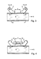
- Fig. 2 to Fig. 4 are schematic representations of various embodiments of the device according to the invention to see.
- the position and status display unit 12 conveys to the operating personnel the information necessary for positioning the ultrasonic transducers 2, 3.
- the status and position display is performed via a display 13, which is integrated in the control / evaluation unit 6.
- the direction indicator of the displacement of the ultrasonic transducers 2,3 is shown in the case shown by arrows; In particular, it is symbolized here that the ultrasonic transducers 2, 3 must have a greater distance c from each other. The amount of shift required can be displayed along the length of the arrows.
- Achieving the predetermined distance c of the ultrasonic transducers 2, 3 can be symbolized for example by a disappearance of the arrows, or it appears a corresponding text, eg 'sensor position reached' or a corresponding generally understandable symbol.
- Fig. 3 shows an alternative embodiment of the status and position display unit 12 according to the invention in a clamp-on ultrasonic flowmeter 1.
- the display takes place here via the two playback elements 14, which are in the simplest case to light-emitting diodes. For example, it is indicated by the color or by flashing of the light emitting diodes in which direction the two ultrasonic transducers 2, 3 have to be displaced or whether the correct position - characterized by the ideal coupling points A, B - has already been reached.
- the two ultrasonic transducers 2, 3 are connected to one another via a guide element, in particular via a rail 15.
- This rail 15 may be formed as a measuring system. Alternatively, it is provided that the measuring system is integrated in the rail 15. The measuring system also determines the distance c between the two ultrasonic transducers 2, 3 and indicates a possibly required shift. By the rail 15, the axis-parallel displacement of the two ultrasonic transducers 2, 3 is relieved relative to the tube 7. As already mentioned, such positioning units have already become known as such from the prior art.
- the display of the direction of displacement is in turn carried out on a display 13.
- the necessary shift is in the form of a number on the display 13, e.g. represented by a linear potentiometer with digital display.
- one or more light-emitting diodes can be mounted on the guide element 15.
- an acoustic display is possible.
- a preferred embodiment of the device according to the invention proposes that the ultrasonic transducers 2, 3 automatically in the correct position according to the deviation of the current value of the characteristic size of the corresponding predetermined size be moved. In this case, can be completely dispensed with the display unit 12. Only the positioning mechanism as such must be automated. Corresponding automatic positioning mechanisms are well known from many fields of application (eg from material processing).
Landscapes
- Physics & Mathematics (AREA)
- Fluid Mechanics (AREA)
- General Physics & Mathematics (AREA)
- Electromagnetism (AREA)
- Measuring Volume Flow (AREA)
- Examining Or Testing Airtightness (AREA)
- Paper (AREA)
- Measurement Of Radiation (AREA)
- Electrical Discharge Machining, Electrochemical Machining, And Combined Machining (AREA)
Abstract
Description
Die Erfindung bezieht sich auf eine Vorrichtung zur Postionierung eines Clamp-On Durchflußmeßgeräts an einem Behältnis, das von einem Medium durchströmt wird.The invention relates to a device for postioning a clamp-on flowmeter on a container which is flowed through by a medium.
Clamp-on Ultraschall-Durchflußmeßgeräte werden vielfach in der Prozeß- und Automatisierungstechnik eingesetzt. Sie erlauben es, den Volumen- und/oder Massenstrom eines Mediums in einem Behältnis, insbesondere in einer Rohrleitung berührungslos zu bestimmen. Weiterhin haben Sie den Vorteil, daß sie von außen an die Rohrleitung angebracht werden können. Clamp-On Ultraschall-Durchflußmeßgeräte sind beispielsweise in der
Die bekannten Ultraschall-Durchflußmeßgeräte arbeiten entweder nach dem Doppler-Prinzip oder nach dem Laufzeitdifferenz-Prinzip. Beim Laufzeitdifferenz-Prinzip wird die unterschiedliche Laufzeit von Ultraschall-Meßsignalen in Strömungsrichtung und entgegen der Strömungsrichtung des Mediums ausgewertet. Hierzu werden die Ultraschall-Meßsignale von den Ultraschallwandlern wechselweise in Strömungsrichtung und entgegen der Strömungsrichtung des Mediums ausgesendet bzw. empfangen. Anhand der Laufzeitdifferenz der Ultraschall-Meßsignale läßt sich die Fließgeschwindigkeit und damit bei bekanntem Durchmesser des Rohres der Volumendurchfluß bzw. bei bekannter Dichte des Mediums der Massendurchfluß bestimmen.The known ultrasonic flowmeters operate either on the Doppler principle or on the transit time difference principle. When running time difference principle, the different duration of ultrasonic measuring signals in the flow direction and against the flow direction of the medium is evaluated. For this purpose, the ultrasonic measuring signals are alternately transmitted or received by the ultrasonic transducers in the flow direction and counter to the flow direction of the medium. Based on the transit time difference of the ultrasonic measuring signals, the flow rate and thus at a known diameter of the tube of the volume flow or at a known density of the medium mass flow can be determined.
Beim Doppler-Prinzip werden Ultraschall-Meßsignale mit einer vorgegebenen Frequenz in das strömende Medium eingekoppelt. Die in dem Medium reflektierten Ultraschall-Meßsignale werden ausgewertet. Anhand einer zwischen dem eingekoppelten und dem reflektierten Ultraschall-Meßsignal auftretenden Frequenzverschiebung läßt sich ebenfalls die Fließgeschwindigkeit des Mediums bzw. der Volumen und/oder Massenstrom bestimmen. Der Einsatz von Durchflußmeßgeräten, die nach dem Doppler-Prinzip arbeiten, ist nur möglich, wenn in dem Medium Luftbläschen oder Verunreinigungen vorhanden sind, an denen die Ultraschall-Meßsignale reflektiert werden. Damit ist der Einsatz derartiger Ultraschall-Durchflußmeßgeräte im Vergleich zu den Ultraschall-Durchflußmeßgeräten, die nach dem Laufzeitdifferenz-Prinzip arbeiten, ziemlich eingeschränkt.In the Doppler principle, ultrasonic measurement signals are coupled into the flowing medium at a predetermined frequency. The reflected in the medium ultrasonic measurement signals are evaluated. On the basis of an occurring between the coupled and the reflected ultrasonic measurement signal frequency shift can also be the flow rate determine the medium or the volume and / or mass flow. The use of flow meters, which operate on the Doppler principle, is only possible if in the medium air bubbles or impurities are present at which the ultrasonic measurement signals are reflected. Thus, the use of such ultrasonic flowmeters compared to the ultrasonic flowmeters, which operate on the transit time difference principle, rather limited.
Bei Clamp-On Ultraschall-Durchflußmeßgeräten, die nach dem Laufzeitdifferenz-Prinzip arbeiten, werden die Ultraschall-Meßsignale unter einem vorgegebenen Winkel in das Behältnis, in dem sich das Medium befindet, eingestrahlt. Damit ein möglichst großer Anteil der von einem Ultraschallwandler in das Behältnis eingestrahlten Energie im jeweils anderen Ultraschallwandler empfangen wird, müssen die beiden Ultraschallwandler einen definierten Abstand voneinander haben. Die jeweilige Position der Ultraschallwandler am Behältnis ist abhängig von dem Innendurchmesser der Rohrleitung und von der Schallgeschwindigkeit des Mediums. Als weitere Applikationsparameter, denen mitunter ein relativ großer Fehler anhaftet, sind die Wandstärke der Rohrleitung und die Schallgeschwindigkeit des Materials der Rohrleitung zu nennen.In clamp-on ultrasonic flowmeters, which operate on the transit time difference principle, the ultrasonic measurement signals are irradiated at a predetermined angle in the container in which the medium is located. In order that the largest possible proportion of the energy radiated into the container by an ultrasonic transducer is received in the other ultrasonic transducer, the two ultrasonic transducers must have a defined distance from one another. The respective position of the ultrasonic transducer on the container is dependent on the inner diameter of the pipeline and on the speed of sound of the medium. Other application parameters to which a relatively large error sometimes adheres include the wall thickness of the pipeline and the speed of sound of the material of the pipeline.
Je nach Applikationsfall tritt bei Clamp-On Durchflußmeßgeräten noch eine weitere Fehlerquelle auf, die durch Temperaturänderungen des Mediums oder der Umgebung hervorgerufen wird. Ein Ultraschallwandler, der bei einem Clamp-On Durchflußmeßgerät eingesetzt wird, weist zumindest ein die Ultraschall-Meßsignale erzeugendes piezoelektrisches Element und einen Koppelkeil auf. Der Koppelkeil ist üblicherweise aus Kunststoff gefertigt und dient einerseits dazu, die Ultraschallsignale unter einem definierten Winkel ins Rohr einzustrahlen und andererseits der Impedanzanpassung.Die in einem piezoelektrischen Element erzeugten Ultraschall-Meßsignale werden über den Koppelkeil bzw. den Vorlaufkörper und die Rohrwand in das flüssige Medium geleitet. Da die Schallgeschwindigkeiten in einer Flüssigkeit und in Kunststoff voneinander verschieden sind, werden die Ultraschallwellen beim Übergang von einem Medium in das andere gebrochen. Der Brechungswinkel selbst bestimmt sich nach dem Snellius Gesetz, d.h der Brechungswinkel ist abhängig von dem Verhältnis der Ausbreitungsgeschwindigkeiten der beiden Medien. Mit Koppelkeilen bzw. Vorlaufkörpern aus Kunststoff läßt sich i.a. eine gute Impedanzanpassung erzielen; allerdings zeigt die Schallgeschwindigkeit von Kunststoff eine relativ starke Temperaturabhängigkeit. Typischerweise verändert sich die Schallgeschwindigkeit von Kunststoff von ca. 2500 m/s bei 25° C auf ca. 2200 m/s bei 130° C. Zusätzlich zu der durch die Temperatur hervorgerufenen Änderung der Laufzeit der Ultraschall-Meßsignale im Kunststoff des Koppelkeils, ändert sich auch die Ausbreitungsrichtung der Ultraschall-Meßsignale in dem strömenden Medium. Beide Änderungen wirken sich bei einem nach der Laufzeitdifferenz-Methode arbeitenden Ultraschall-Durchflußmeßgerät daher ungünstig auf die Meßgenauigkeit aus. Um die Meßgenauigkeit auf einem konstanten hohen Maß zu halten, sind daher Korrekturen der Position der Ultraschallwandler erforderlich.
Die Winkelpositionierung der Ultraschallwandler ist bei den bekannten Durchflußmeßgeräten fest vorgegeben. Zwecks Erstmontage oder im Falle späterer Applikationsänderungen ist es aufgrund des Zuvorgesagten erforderlich, den Abstand der beiden Ultraschallwandler definiert aufeinander einzustellen. Hierzu wird üblicherweise einer der beiden Ultraschallwandler solange relativ zum anderen verschoben, bis die Position ermittelt ist, in der die Intensität der von den Ultraschallwandlern empfangenen Meßsignale maximal ist. Nachdem der optimale Abstand der beiden Ultraschallwandler auf diesem 'Trial/Error' Weg ermittelt ist, werden die beiden Ultraschallwandler in der ermittelten Position fest an der Rohrwand arretiert. Dieses Verfahren ist natürlich relativ zeitintensiv. Zur Vereinfachung der relativen Bewegung der Ultraschallwandler werden mechanische Positionierhilfen wie Millimieterskalen oder Lochleisten eingesetzt. Eine Positionierhilfe, die mit einer Lochleiste arbeitet, ist beispielsweise in der
The angular positioning of the ultrasonic transducer is fixed in the known flow meters. For the purpose of initial assembly or in case of later application changes, it is necessary due to the predicted to set the distance of the two ultrasonic transducers defined each other. For this purpose, one of the two ultrasonic transducers is usually displaced relative to the other until the position in which the intensity of the measurement signals received by the ultrasonic transducers is maximum is determined. After the optimum distance between the two ultrasonic transducers has been determined on this 'trial / error' path, the two ultrasonic transducers are firmly locked to the pipe wall in the determined position. Of course, this procedure is relatively time consuming. To simplify the relative movement of the ultrasonic transducers, mechanical positioning aids such as millimeter scales or perforated strips are used. A positioning aid that works with a perforated strip, for example, in the
Hinzu kommt, daß einige der Applikationsparameter, die insbesondere bei einem Clamp-On Durchflußmeßgerät zur exakten Bestimmung des Volumendurchflusses notwendig sind, in den seltensten Fällen genau genug bekannt sind - oder aber die Ermittlung dieser Parameter ist ziemlich aufwendig. Während die Bestimmung des Außendurchmessers der Rohrleitung kaum Probleme bereitet, kann die exakte Ermittlung der Wandstärke der Rohrleitung durchaus problematisch sein. In vielen Fällen ist darüber hinaus weder die Schallgeschwindigkeit des Materials der Rohrleitung noch die Schallgeschwindigkeit des Mediums exakt bekannt.In addition, some of the application parameters, which are necessary in particular for a clamp-on flowmeter for the exact determination of the volume flow, in the rarest cases are known exactly enough - or the determination of these parameters is quite expensive. While the determination of the outer diameter of the pipeline hardly causes problems, the exact determination of the wall thickness of the pipeline can be quite problematic. In many cases, neither the speed of sound of the material of the pipeline nor the speed of sound of the medium is known exactly.
Der Erfindung liegt die Aufgabe zugrunde, eine Vorrichtung vorzuschlagen, mit der die Positionierung eines Clamp-On Durchflußmeßgeräts an einem Behältnis vereinfacht wird.The invention has for its object to propose a device with which the positioning of a clamp-on flowmeter is simplified to a container.
Die Aufgabe wird dadurch gelöst, daß zwei Ultraschallwandlern vorgesehen sind, die Meßsignale in das Behältnis aussenden und/oder aus dem Behältnis empfangen; desweiteren sind eine Positioniereinheit zur variablen Positionierung der Ultraschallwandler an dem Behältnis und eine Regel-/Auswerteeinheit vorgesehen, wobei die Regel-/Auswerteeinheit aus vorgegebenen Prozeß- und/oder Systemgrößen eine charakteristische SOLL-Größe der Meßsignale errechnet und anhand eines Vergleichs der errechneten SOLL-Größe mit der entsprechenden gemessenen IST-Größe ermittelt, ob die Ultraschallwandler optimal positioniert sind oder ob die Position der Ultraschallwandler zu verändern ist. Darüber hinaus kommt eine Anzeigeeinheit zum Einsatz, die eine erforderliche Positionsänderung und/oder die Richtung, in der eine Positionsänderung zu erfolgen hat, zur Anzeige bringt.The object is achieved in that two ultrasonic transducers are provided which emit measurement signals in the container and / or receive from the container; Furthermore, a positioning unit for the variable positioning of the ultrasonic transducers on the container and a control / evaluation unit are provided, wherein the control / evaluation of predetermined process and / or system sizes calculates a characteristic target size of the measured signals and based on a comparison of the calculated target Size with the corresponding measured actual size determines whether the ultrasonic transducers are optimally positioned or whether the position of the ultrasonic transducers is to be changed. In addition, a display unit is used, which brings a required change in position and / or the direction in which a position change has to be made to display.
Erfindungsgemäß erfolgt eine Erkennung einer Fehlpositionierung der Ultraschallwandler und eine diese Fehlpositionierung ausgleichende Gegenmaßnahme aufgrund der von der in jeweils einem Ultraschallwandler empfangenen Signale. Anhand der empfangenen Meßsignale wird zumindest eine unter den Applikationsbedingungen auftretende charakteristische IST-Größe des Meßsignals ermittelt.According to the invention, a detection of a malpositioning of the ultrasound transducers and a countermeasure compensating for this mispositioning takes place on the basis of the signals received in each case by an ultrasound transducer. On the basis of the received measurement signals is at least determines a occurring under the application conditions characteristic actual size of the measured signal.
Bei der chrakteristischen Größe handelt es sich bevorzugt um die Intensität der Meßsignale und/oder um die Laufzeit der Meßsignale. Dieser gemessene Wert wird mit einer entsprechenden charakteristischen SOLL-Größe verglichen. Handelt es sich bei der charakteristischen Größe um die Laufzeit, so wird die entsprechende SOLL-Größe errechnet, wobei zwecks Berechnung das Brechungsgesetz von Snellius zur Anwendung kommt. Üblicherweise sind nicht alle in den entsprechenden Gleichungen genannten Größen exakt bekannt. So ist in vielen Fällen die exakte Schallgeschwindigkeit des Mediums nicht bekannt. In einem solchen Fall wird der z.B. anhand einer Tabelle ersichtliche, wahrscheinlichste Wert für die Schallgeschwindigkeit des Mediums eingesetzt. Alternativ ist es möglich, die Schallgeschwindigkeit des Mediums anhand einer Messung zu bestimmen, indem die Laufzeit von Ultraschallwellen in senkrechter Richtung zur Fließrichtung des Mediums gemessen wird. Derartige Verfahren werden bereits in der Praxis angewendet, so daß an dieser Stelle auf eine exakte Beschreibung verzichtet werden kann.The characteristic value is preferably the intensity of the measurement signals and / or the transit time of the measurement signals. This measured value is compared with a corresponding characteristic target size. If the characteristic quantity is the transit time, the corresponding target size is calculated using the law of refraction of Snellius for the purpose of calculation. Usually, not all quantities mentioned in the corresponding equations are exactly known. Thus, in many cases, the exact speed of sound of the medium is not known. In such a case, the e.g. using a table, most likely value for the speed of sound of the medium used. Alternatively, it is possible to determine the sound velocity of the medium by means of a measurement by measuring the transit time of ultrasonic waves in the direction perpendicular to the flow direction of the medium. Such methods are already used in practice, so that can be dispensed with an exact description at this point.
Gemäß einer bevorzugten Ausgestaltung der erfindungsgemäßen Vorrichtung ist die Anzeigeeinheit derart ausgestaltet, daß sie dem Bedienpersonal die korrekte Position der Ultraschallwandler auf optischem und/oder auf akustischem Wege signalisiert oder daß die Anzeigeeinheit dem Bedienpersonal ggf. sukzessive Hinweise gibt, in welcher Richtung zumindest einer der Ultraschallwandler zwecks korrekter Positonierung zu verschieben ist. Eine vorteilhafte Ausgestaltung der erfindungsgemäßen Vorrichtung schlägt vor, daß die Anzeigeeinheit integraler Teil des Clamp-On Druchflußmeßgerätes ist. Insbesondere ist vorgesehen, daß es sich bei der Anzeigeeinheit um ein Display handelt.According to a preferred embodiment of the device according to the invention, the display unit is configured such that it signals to the operator the correct position of the ultrasonic transducer on optical and / or acoustically or that the display unit, if necessary, gives the operators successive hints in which direction at least one of the ultrasonic transducers to postpone for correct positioning. An advantageous embodiment of the device according to the invention suggests that the display unit is an integral part of the clamp-on Druchflußmeßgerätes. In particular, it is provided that the display unit is a display.
Die Information an den Anwender kann beispielsweise dadurch erfolgen, daß die Verschieberichtung und/oder der Betrag der Verschiebung der beiden Ultraschallwandler auf der Anzeigeeinheit in numerischen und/oder in graphischen Symbolen zur Anzeige kommt.The information to the user can be effected, for example, by indicating the direction of displacement and / or the amount of displacement of the two ultrasonic transducers on the display unit in numerical and / or graphic symbols.
Prinzipiell kann es sich bei der Anzeigeeinheit um zumindest ein optisches und/oder um zumindest ein akustisches Wiedergabe-Element handelt, wobei das jeweils verwendete Element in verschiedenen Modi betreibbar ist.In principle, the display unit may be at least one optical and / or at least one acoustic reproduction element, the element used in each case being operable in different modes.
Insbesondere kann es sich bei dem optischen Wiedergabe-Element um eine Leuchtdiode handeln, wobei es sich bei den Modi in diesem Fall z.B. um einen Blinkmodus, um einen Ein-Modus und/oder um einen Aus-Modus handelt.In particular, the optical display element may be a light-emitting diode, with the modes in this case being e.g. is a flashing mode, an on mode and / or an off mode.
Alternativ oder zusätzlich ist das optische Wiedergabe-Element so ausgestaltet, daß den unterschiedlichen Modi unterschiedliche Farbkennzeichnungen und/oder Symbole zugeordnet sind.Alternatively or additionally, the optical reproduction element is designed such that different color codes and / or symbols are assigned to the different modes.
Kommt ein akustisches Wiedergabe-Element zum Einsatz, so ist es bevorzugt derart ausgestaltet, daß die unterschiedlichen Modi durch unterschiedliche Tonhöhen und/oder durch unterschiedliche Wiederholfrequenzen von zumindest einer Tonhöhe realisiert sind.If an acoustic reproduction element is used, then it is preferably designed such that the different modes are realized by different pitches and / or by different repetition frequencies of at least one pitch.
Die Erfindung wird anhand der nachfolgenden Zeichnungen näher erläutert. Es zeigt:
-
Fig. 1 : eine schematische Darstellung des Schallpfades eines Ultraschallmeßsignals in einer Rohrleitung, -
Fig. 2 : eine schematische Darstellung einer ersten Ausgestaltung der erfindungsgemäßen Vorrichtung, -
Fig. 3 : eine schematische Darstellung einer zweiten Ausgestaltung der erfindungsgemäßen Vorrichtung und -
Fig. 4 : eine schematische Darstellung einer dritten Ausgestaltung der erfindungsgemäßen Vorrichtung.
-
Fig. 1 : a schematic representation of the sound path of a Ultraschallmeßsignals in a pipeline, -
Fig. 2 : a schematic representation of a first embodiment of the device according to the invention, -
Fig. 3 : a schematic representation of a second embodiment of the device according to the invention and -
Fig. 4 : a schematic representation of a third embodiment of the device according to the invention.
Wesentliche Komponenten des Clamp-On Ultraschall-Durchflußmeßgerätes 1 sind die beiden Ultraschallwandler bzw. Ultraschallsensoren 2, 3 und die Regel-/Auswerteeinheit 8. Die beiden Ultraschallwandler 2, 3 sind mittels einer in der
Ein Ultraschallwandler 2; 3 weist als wesentliche Bestandteile zumindest ein piezoelektrisches Element 4; 5, das die Ultraschall-Meßsignale erzeugt und/oder empfängt, und einen Koppelkeil 6; 16 auf. Die Ultraschall-Meßsignale werden über den Koppelkeil 6; 16 und über die Rohrwand 10 in das vom Medium 9 durchströmte Rohr 7 eingekoppelt bzw. aus dem Rohr 7 ausgekoppelt.
Die beiden Ultraschallwandler 2, 3 sind derart ausgestaltet, daß sie Ultraschall-Meßsignale aussenden und empfangen. Der optimale Abstand c der beiden Ultraschallwandler 2, 3 ist - wie bereits an vorhergehender Stelle beschrieben - von verschiedenen System- und oder Prozeßgrößen abhängig.An
The two
Um sicherzustellen, daß die maximale Energie, die von einem Ultraschallwandler 2; 3 ausgesendet wird, auch in dem jeweils anderen Ultraschallwandler 3; 2 empfangen wird, ist eine auf den jeweiligen Anwendungsfall abgestimmte Positionierung der Ultraschallwandler 2, 3 erforderlich. Bei diesen System- und Prozeßgrößen handelt es sich beispielsweise um den Innendurchmesser di des Rohres 7, um die Wandstärke dr des Rohres 7, um die Schallgeschwindigkeit cr des Materials, aus dem das Rohr 7 gefertigt ist, oder um die Schallgeschwindigkeit cm des Mediums 9. Prinzipiell ist eine Justierung der Ultraschallwandler 2, 3 sowohl bei der Erstmontage als auch immer dann erforderlich, wenn es zu einer wesentlichen Änderung von zumindest einer Prozeß- und/oder Systemgröße kommt.To ensure that the maximum energy generated by an
In dem gezeigten Ausführungsbeispiel ist der Abstand c der beiden Ultraschallwandler 2, 3 so bemessen, daß sich die Ultraschall-Meßsignale, die entsprechend der Laufzeitdifferenz-Methode wechselweise von den beiden Ultraschallwandlern 2, 3 ausgesendet und empfangen werden, über nur einen Schallpfad SP in dem vom Medium 9 durchströmten Behältnis 7 ausbreiten. Der Schallpfad SP hat zwei Traversen. Eine Traverse kennzeichnet den Teilbereich des Schallpfades SP, auf dem ein Ultraschall-Meßsignal den Behälter 7 einmal quert. Die Querung kann diametral oder kordial sein.In the embodiment shown, the distance c of the two
Sind die nachfolgend genannten Größen zumindest näherungsweise bekannt, so läßt sich die SOLL-Größe, die erfindungsgemäß der Positions- und Statusanzeigeeinheit vorgegebenen wird, errechnen. Bei den Größen handelt es sich im einzelnen um:
- den Abstand ds eines Ultraschallwandlers 2; 3
zur Rohrwand 10; - die Dicke
dr der Rohrwand 10; - den Innendurchmesser di des
Rohres 7; - die Schallgeschwindigkeit
cs im Vorlaufkörper 6; 7; - die Schallgeschwindigkeit
cr im Rohr 7; - die Schallgeschwindigkeit
cm im Medium 9; - den Winkel as
im Ultraschallwandler 2; 3; - den Winkel
ar im Rohr 7; - den Winkel am im Medium;
- die Anzahl n der Traversen. Im gezeigten Fall ist n = 2.
- the distance ds of an
ultrasonic transducer 2; 3 to thepipe wall 10; - the thickness dr of the
tube wall 10; - the inner diameter di of the
pipe 7; - the speed of sound cs in the
flow body 6; 7; - the speed of sound cr in the
pipe 7; - the speed of sound cm in the
medium 9; - the angle as in the
ultrasonic transducer 2; 3; - the angle ar in the
pipe 7; - the angle at the medium;
- the number n of the traverses. In the case shown, n = 2.
Der Einstrahlwinkel ar im Rohr 7 läßt sich unter Zuhilfenahme des Snellius' Gesetzes durch die folgende Formel darstellen: 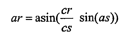
Der Einfallwinkel am ins Medium 9 läßt sich durch die folgende Formel beschreiben : 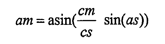
Die Laufzeit Tsoll der Ultraschall-Meßsignale auf dem Schallpfad SP läßt sich dann anhand der nachfolgenden Formel berechnen: 
Sind alle Parameter bekannt, so berechnet sich die Laufzeit Tsoll des Ultraschall-Meßsignals nach obiger Formel. Hierbei wurde übrigens die Annahme getroffen, daß in der Rohrleitung 7 der Durchfluß Null ist. In einer Vielzahl von Anwendungsfällen ist nun zumindest die Schallgeschwindigkeit cm des Mediums 9 nicht bekannt. Folglich stimmt die gemessene Laufzeit Tist nicht mit der errechneten Laufzeit Tsoll überein, da in vielen Fällen für die Schallgeschwindigkeit cm des Mediums 9 zwecks Vereinfachung ein Schätzwert genommen wird. Ein besseres Ergebnis läßt sich erzielen, wenn die Schallgeschwindigkeit cm des Mediums 9 in einem separaten Verfahrensschritt gemessen wird.If all parameters are known, the transit time Tsoll of the ultrasonic measurement signal is calculated according to the above formula. Incidentally, the assumption was made that in the
Anschließend wird die tatsächliche Laufzeit Tist des Ultraschall-Meßsingals gemessen und mit der errechneten Laufzeit Tsoll verglichen. Ergibt sich anhand des Vergleichs, daß die gemessene Lauzeit Tist größer ist als die vorgegebene Laufzeit Tsoll, so müssen die beiden Ultraschallwandler 2, 3 näher zusammengerückt werden, der Abstand c der beiden Ultraschallwandler 2, 3 wird also verringert. Ist hingegen die gemessene Lauzeit Tist kleiner als die vorgegebene Laufzeit Tsoll, so müssen die beiden Ultraschallwandler 2, 3 auseinander gerückt werden, d.h. der Abstand c wird vergrößert. Erfindungs-gemäß wird dem Bedienpersonal nun zur Anzeige gebracht, in welcher Richtung und ggf. um welchen Wert die Relativbewegung der Ultraschall-wandler 2, 3 zu erfolgen hat.Subsequently, the actual transit time Tact of the ultrasonic measuring signal is measured and compared with the calculated transit time Tset . If, on the basis of the comparison, it is found that the measured lead time Tact is greater than the predefined propagation time Tset , the two
In den Figuren
In
Die Anzeige der Verschieberichtung erfolgt wiederum auf einem Display 13. Beispielsweise wird die notwendige Verschiebung in Form einer Zahl auf dem Display 13 z.B. mittels eines Linearpotis mit Digitalanzeige dargestellt. Es versteht sich von selbst, daß zwecks Anzeige der erforderlichen Verschiebung der Ultraschallwandler 2, 3 auch eine oder mehrere Leuchtdioden auf dem Führungselement 15 angebracht sein können. Darüber hinaus ist in allen Fällen anstelle der optischen Anzeige alternativ oder zusätzlich eine akustische Anzeige möglich.The display of the direction of displacement is in turn carried out on a
Weiterhin schlägt eine bevorzugte Ausgestaltung der erfindungsgemäßen Vorrichtung vor, daß die Ultraschallwandler 2, 3 entsprechend der Abweichung des aktuellen Werts der charakteristischen Größe von der entsprechenden vorgegebenen Größe automatisch in die korrekte Position verfahren werden. In diesem Fall kann auf die Anzeigeeinheit 12 auch gänzlich verzichtet werden. Lediglich der Positioniermechanismus als solcher muß automatisiert werden. Entsprechende automatische Positioniermechanismen sind aus vielen Anwendungsbereichen (z. B. aus der Materialbearbeitung) hinlänglich bekannt.Furthermore, a preferred embodiment of the device according to the invention proposes that the
- 11
- Ultraschall-DurchflußmeßgerätUltrasonic flowmeter
- 22
- Ultraschallwandlerultrasound transducer
- 33
- Ultraschallwandlerultrasound transducer
- 44
- Piezoelektrisches ElementPiezoelectric element
- 55
- Piezoelektrisches ElementPiezoelectric element
- 66
- Koppelkeil / VorlaufkörperCoupling wedge / flow body
- 77
- Behältnis / RohrContainer / tube
- 88th
- Regel-/AuswerteeinheitControl / evaluation unit
- 99
- Mediummedium
- 1010
- Rohrwandpipe wall
- 1111
- Positioniereinheitpositioning
- 1212
- Anzeigeeinheitdisplay unit
- 1313
- Displaydisplay
- 1414
- Wiedergabe-ElementPlayback element
- 1515
- Schiene / FührungselementRail / guide element
- 1616
- Koppelkeil / VorlaufkörperCoupling wedge / flow body
- SS
- Strömungsrichtungflow direction
- SPSP
- Schallpfadsound path
- dsds
- Abstand Ultraschallwandler zur RohrwandDistance ultrasonic transducer to the pipe wall
- drdr
- Dicke der RohrwandThickness of the pipe wall
- didi
- Innendurchmesser des RohresInner diameter of the tube
- cscs
- Schallgeschwindigkeit im VorlaufkörperSpeed of sound in the flow body
- crcr
- Schallgeschwindigkeit im RohrSpeed of sound in the pipe
- cmcm
- Schallgeschwindigkeit im MediumSpeed of sound in the medium
- asas
- Winkel im UltraschallwandlerAngle in the ultrasonic transducer
- arar
- Winkel im RohrAngle in the pipe
- amat the
- Winkel im MediumAngle in the medium
- nn
- Anzahl TraversenNumber of traverses
- cc
- Abstand der UltraschallwandlerDistance of the ultrasonic transducers
Claims (10)
- Unit for positioning a clamp-on flowmeter (1) on a container (7) through which a medium (9) flows with at least two ultrasonic converters (2; 3) that transmit measuring signals to the container (7) and/or receive measuring signals from the container (7), with a positioning unit (11) to variably position the ultrasonic converters (2, 3) on the container (7), characterized in that:- it is provided with a control/evaluation unit (8) that calculates a characteristic TARGET variable (Ttarget) of the measuring signals from prespecified process and/or system variables, and compares the TARGET variable (Ttarget) with the ACTUAL variable measured (Tactual) to determine whether the ultrasonic converters (2, 3) are optimally positioned and whether the position of the ultrasonic converters (2, 3) has to be changed- it is provided with a display unit (12) which tells the operating staff whether a position change is needed and/or indicates the direction in which a position change is to take place.
- Unit as per Claim 1, characterized in that:the display unit (12) is designed in such a way that it optically and/or acoustically signals the correct position of the ultrasonic converters (2, 3) to the operating staff, or characterized in that the display unit (12) gives the operating staff consecutive hints as to the direction the ultrasonic converters (2, 3) have to be moved to position them correctly.
- Unit as per Claim 1 or 2, characterized in that:the display unit (12) is an integral part of the clamp-on flowmeter (1).
- Unit as per Claim 1 or 3, characterized in that:the display unit (12) is a display (13).
- Unit as per Claim 4, characterized in that:the direction of movement and/or the amount of movement of the two ultrasonic converters (2, 3) is displayed on the display unit in numeric and/or graphic symbols.
- Unit as per Claim 1 or 3, characterized in that:the display unit (12) is at least one optical and/or one acoustic representation element (14), and various operating modes are associated with the particular representation element (14).
- Unit as per Claim 6, characterized in that:the optical representation element (14) is a light emitting diode and the associated modes are a flashing mode, an "on" mode and an "off" mode.
- Unit as per Claim 6, characterized in that:the optical representation element (14) is designed in such a way that different colors and/or symbols are assigned to the various modes.
- Unit as per Claim 6, characterized in that:the acoustic representation element (14) is designed in such a way that the different modes are implemented by different pitches and/or by different frequencies at which at least one pitch is repeated.
- Unit as per one of the previous claims, characterized in that:the characteristic variable refers to the intensity of the measuring signals and/or the run time (T) of the measuring signals.
Applications Claiming Priority (3)
| Application Number | Priority Date | Filing Date | Title |
|---|---|---|---|
| DE10258997A DE10258997A1 (en) | 2002-12-16 | 2002-12-16 | Clamp-on ultrasonic flow meter for measuring mass flow rates in pipes or conduits, uses evaluation and control unit to optimize transducer positions based on comparison of a measurement value with a reference value |
| DE10258997 | 2002-12-16 | ||
| PCT/EP2003/013838 WO2004055484A2 (en) | 2002-12-16 | 2003-12-06 | Device for positioning a clamp-on flowmeter on a container |
Publications (2)
| Publication Number | Publication Date |
|---|---|
| EP1573276A2 EP1573276A2 (en) | 2005-09-14 |
| EP1573276B1 true EP1573276B1 (en) | 2009-06-10 |
Family
ID=32336401
Family Applications (1)
| Application Number | Title | Priority Date | Filing Date |
|---|---|---|---|
| EP03789157A Expired - Lifetime EP1573276B1 (en) | 2002-12-16 | 2003-12-06 | Device for positioning a clamp-on flowmeter on a container |
Country Status (8)
| Country | Link |
|---|---|
| US (1) | US7240566B2 (en) |
| EP (1) | EP1573276B1 (en) |
| CN (1) | CN100383495C (en) |
| AT (1) | ATE433564T1 (en) |
| AU (1) | AU2003293786A1 (en) |
| DE (2) | DE10258997A1 (en) |
| DK (1) | DK1573276T3 (en) |
| WO (1) | WO2004055484A2 (en) |
Cited By (1)
| Publication number | Priority date | Publication date | Assignee | Title |
|---|---|---|---|---|
| WO2020126281A1 (en) | 2018-12-21 | 2020-06-25 | Endress+Hauser Flowtec Ag | Method for putting into operation and/or checking an ultrasound throughflow measuring point |
Families Citing this family (16)
| Publication number | Priority date | Publication date | Assignee | Title |
|---|---|---|---|---|
| DE102004031274B4 (en) * | 2004-06-28 | 2007-07-12 | Flexim Flexible Industriemesstechnik Gmbh | Method for calibrating ultrasonic clamp-on flowmeters |
| DE102004031637A1 (en) * | 2004-06-30 | 2006-01-26 | Abb Patent Gmbh | Method for operating a measuring device, in particular a flow measuring device |
| DE102005023269A1 (en) * | 2005-05-20 | 2006-11-23 | Ksb Aktiengesellschaft | Method and device for monitoring a cleaning system for containers |
| DE102005045485A1 (en) | 2005-09-22 | 2007-04-12 | Endress + Hauser Flowtec Ag | Method for system and / or process monitoring in an ultrasonic flowmeter |
| DE102005052550B3 (en) * | 2005-11-02 | 2007-02-08 | Krohne Ag | Clamp-on ultrasound flow-through measuring device comprises a guiding frame fixed to a fixing unit so that it moves away from or toward a tube and pivots along a pivoting axis |
| DE102006000693A1 (en) * | 2006-01-02 | 2007-07-05 | Endress + Hauser Flowtec Ag | Device for determining and / or monitoring the volume or mass flow of a medium |
| DE102007024017A1 (en) * | 2007-05-22 | 2008-11-27 | Ksb Aktiengesellschaft | Device and method for monitoring a cleaning and / or ventilation system |
| DE102008029772A1 (en) | 2008-06-25 | 2009-12-31 | Endress + Hauser Flowtec Ag | Method and measuring system for determining and / or monitoring the flow of a measuring medium through a measuring tube |
| DE102011005170B4 (en) * | 2011-03-07 | 2012-10-11 | Flexim Flexible Industriemesstechnik Gmbh | Method for ultrasonic clamp-on flow measurement and apparatus for implementing the method |
| DE102012112516A1 (en) * | 2012-12-18 | 2014-06-18 | Endress + Hauser Flowtec Ag | Method for verifying the reliability of measured data measured by an ultrasonic flow measurement according to the transit time difference method and ultrasonic flowmeter |
| FR3014203B1 (en) * | 2013-11-29 | 2015-12-25 | Thales Sa | DEVICE AND METHOD FOR MONITORING A FLOW PRESSURE MEASUREMENT PROBE |
| US10458831B2 (en) * | 2017-07-05 | 2019-10-29 | Saudi Arabian Oil Company | System and method for acoustic container volume calibration |
| US10495499B2 (en) * | 2017-10-27 | 2019-12-03 | METER Group, Inc. USA | Sonic anemometer |
| EP3489634B1 (en) * | 2017-11-22 | 2020-08-05 | Levitronix GmbH | Ultrasonic measuring device and method for the ultrasonic measurement of a flowing fluid |
| FR3080683B1 (en) * | 2018-04-30 | 2023-03-17 | Buerkert Werke Gmbh & Co Kg | FLUID MEASURING MEANS |
| SE542734C2 (en) | 2019-01-30 | 2020-06-30 | Labtrino Ab | Coupling member for clamp on flow metering |
Family Cites Families (15)
| Publication number | Priority date | Publication date | Assignee | Title |
|---|---|---|---|---|
| US3987674A (en) * | 1975-01-03 | 1976-10-26 | Joseph Baumoel | Transducer structure and support for fluid measuring device |
| US4286470A (en) * | 1979-10-19 | 1981-09-01 | Lfe Corporation | Clamp-on ultrasonic transducer |
| US4373401A (en) * | 1980-05-05 | 1983-02-15 | Joseph Baumoel | Transducer structure and mounting arrangement for transducer structure for clamp-on ultrasonic flowmeters |
| US4425803A (en) * | 1980-05-05 | 1984-01-17 | Joseph Baumoel | Transducer structure and mounting arrangement for transducer structure for clamp-on ultrasonic flowmeters |
| US4991441A (en) * | 1987-11-06 | 1991-02-12 | Westinghouse Electric Corp. | Positioning assembly for a transducer in a boresonic inspection system |
| US5131278A (en) * | 1989-06-13 | 1992-07-21 | Joseph Baumoel | Mounting structure for transducers with sonic-energy absorbing means |
| CN2074905U (en) * | 1989-10-31 | 1991-04-10 | 长沙市电子仪器二厂 | Circulation display device for ultrasonic wave flowmeter |
| CN2106357U (en) * | 1991-07-27 | 1992-06-03 | 长沙市电子仪器二厂 | Ultrasonic flowmeter transducer installation positioner |
| JP3216769B2 (en) | 1995-03-20 | 2001-10-09 | 富士電機株式会社 | Temperature and pressure compensation method for clamp-on type ultrasonic flowmeter |
| US6585649B1 (en) * | 1998-05-02 | 2003-07-01 | John D. Mendlein | Methods and devices for improving ultrasonic measurements using multiple angle interrogation |
| JP4782327B2 (en) * | 2001-02-14 | 2011-09-28 | 一正 大西 | Clamp-on type ultrasonic flowmeter |
| JP2002365106A (en) * | 2001-04-02 | 2002-12-18 | Kazumasa Onishi | Instrument for measuring flow rate, clamp-on type ultrasonic flowmeter |
| JP2003075219A (en) * | 2001-09-06 | 2003-03-12 | Kazumasa Onishi | Clamp-on ultrasonic flowmeter |
| DE10147175A1 (en) * | 2001-09-19 | 2003-04-03 | Joerg Rupp Synergetik Gmbh | Ultrasonic measurement system for determining fluid level or mass flow through a pipe or in a container has integral control and analysis electronics together with a mounting and positioning system for flexible positioning |
| US6772636B2 (en) * | 2002-11-06 | 2004-08-10 | Varco I/P, Inc. | Pipe flaw detector |
-
2002
- 2002-12-16 DE DE10258997A patent/DE10258997A1/en not_active Withdrawn
-
2003
- 2003-12-06 DK DK03789157T patent/DK1573276T3/en active
- 2003-12-06 WO PCT/EP2003/013838 patent/WO2004055484A2/en not_active Application Discontinuation
- 2003-12-06 AT AT03789157T patent/ATE433564T1/en not_active IP Right Cessation
- 2003-12-06 US US10/537,353 patent/US7240566B2/en not_active Expired - Fee Related
- 2003-12-06 AU AU2003293786A patent/AU2003293786A1/en not_active Abandoned
- 2003-12-06 CN CNB2003801062541A patent/CN100383495C/en not_active Expired - Fee Related
- 2003-12-06 DE DE50311592T patent/DE50311592D1/en not_active Expired - Lifetime
- 2003-12-06 EP EP03789157A patent/EP1573276B1/en not_active Expired - Lifetime
Cited By (4)
| Publication number | Priority date | Publication date | Assignee | Title |
|---|---|---|---|---|
| WO2020126281A1 (en) | 2018-12-21 | 2020-06-25 | Endress+Hauser Flowtec Ag | Method for putting into operation and/or checking an ultrasound throughflow measuring point |
| DE102018133476A1 (en) | 2018-12-21 | 2020-06-25 | Endress+Hauser Flowtec Ag | Procedure for commissioning and / or checking an ultrasonic flow measuring point |
| DE102018133476B4 (en) | 2018-12-21 | 2023-11-02 | Endress+Hauser Flowtec Ag | Method for commissioning and/or checking a clamp-on ultrasonic flow measuring point |
| US11933657B2 (en) | 2018-12-21 | 2024-03-19 | Endress+Hauser Flowtec Ag | Method for putting into operation and/or checking an ultrasound throughflow measuring point |
Also Published As
| Publication number | Publication date |
|---|---|
| CN100383495C (en) | 2008-04-23 |
| WO2004055484A3 (en) | 2004-11-11 |
| WO2004055484A2 (en) | 2004-07-01 |
| EP1573276A2 (en) | 2005-09-14 |
| AU2003293786A1 (en) | 2004-07-09 |
| ATE433564T1 (en) | 2009-06-15 |
| DE50311592D1 (en) | 2009-07-23 |
| US7240566B2 (en) | 2007-07-10 |
| DK1573276T3 (en) | 2009-09-14 |
| CN1726382A (en) | 2006-01-25 |
| US20060123922A1 (en) | 2006-06-15 |
| DE10258997A1 (en) | 2004-06-24 |
Similar Documents
| Publication | Publication Date | Title |
|---|---|---|
| EP1573276B1 (en) | Device for positioning a clamp-on flowmeter on a container | |
| EP1554549B1 (en) | Flowmeter | |
| DE102008029772A1 (en) | Method and measuring system for determining and / or monitoring the flow of a measuring medium through a measuring tube | |
| EP0691528A2 (en) | Mass flowmeter | |
| DE10254053B4 (en) | Method and device for determining and / or monitoring a volume and / or mass flow | |
| DE102007019689A1 (en) | Device for determining and / or monitoring the volume and / or mass flow of a medium | |
| DE2119802A1 (en) | Densitometer and flow rate monitoring device and associated procedure | |
| EP1608939B1 (en) | Device for determination and/or monitoring of the volumetric and/or mass flow of a medium | |
| EP1754025A2 (en) | Determination of the reception time for an ultrasound signal by means of pulse shape detection | |
| EP1480023B1 (en) | Measurement device with apparatus for recognition of connected ultrasonic sensor | |
| DE10335665B4 (en) | Mass Flow Meter | |
| DE102005042792B3 (en) | Fluid flow speed and/or temperature measuring method for use in e.g. closed flow system, involves deriving flow speed and/or temperature of fluid flowing through measuring sections from simultaneously determined delays of ultrasound signals | |
| EP3314210B1 (en) | Field device having a compensation circuit for eliminating environmental influences | |
| DE2828937C2 (en) | ||
| DE10036565C2 (en) | Device for determining the change in density of a medium | |
| EP1743142B1 (en) | Ultrasonic measuring apparatus for determining and/or monitoring the volume flow rate and/or mass flow rate of a medium | |
| DE10322718B4 (en) | Ultrasonic position measuring system and method therefor | |
| EP4033214A1 (en) | Method for calibrating a temperature measuring unit based on ultrasonic measurement, method for measuring the temperature of a medium, temperature measuring unit and ultrasonic flow meter | |
| EP4302066A1 (en) | Modular measuring device for determining the density of a measurement medium | |
| EP0025026A2 (en) | Device for measuring the flow velocity of a fluid | |
| DE3608384A1 (en) | Method for measuring displacements, in particular for the absolute measurement of short displacements, via the propagation time of pulses in a material support medium, and associated device for carrying out the method | |
| WO2005031369A2 (en) | Ultrasound sensor and method for measuring flow rate | |
| EP4047328A1 (en) | Ultrasonic flow meter and method for determining the velocity of a flowing medium | |
| DE102021117707A1 (en) | Measuring system for measuring a flow parameter of a fluid substance flowing in a pipeline | |
| EP1604176B1 (en) | Device for determining and/or monitoring the volume and/or mass flow rate of a medium |
Legal Events
| Date | Code | Title | Description |
|---|---|---|---|
| PUAI | Public reference made under article 153(3) epc to a published international application that has entered the european phase |
Free format text: ORIGINAL CODE: 0009012 |
|
| 17P | Request for examination filed |
Effective date: 20050601 |
|
| AK | Designated contracting states |
Kind code of ref document: A2 Designated state(s): AT BE BG CH CY CZ DE DK EE ES FI FR GB GR HU IE IT LI LU MC NL PT RO SE SI SK TR |
|
| AX | Request for extension of the european patent |
Extension state: AL LT LV MK |
|
| DAX | Request for extension of the european patent (deleted) | ||
| RIN1 | Information on inventor provided before grant (corrected) |
Inventor name: BERGER, ANDREAS Inventor name: STOCKER, HARALD Inventor name: STRUNZ, TORSTEN Inventor name: BUSSINGER, KLAUS Inventor name: FLEURY, AURELE Inventor name: WIEST, ARMIN Inventor name: BRUMBERG, OLIVER Inventor name: FROEHLICH, THOMAS |
|
| GRAP | Despatch of communication of intention to grant a patent |
Free format text: ORIGINAL CODE: EPIDOSNIGR1 |
|
| GRAS | Grant fee paid |
Free format text: ORIGINAL CODE: EPIDOSNIGR3 |
|
| GRAA | (expected) grant |
Free format text: ORIGINAL CODE: 0009210 |
|
| AK | Designated contracting states |
Kind code of ref document: B1 Designated state(s): AT BE BG CH CY CZ DE DK EE ES FI FR GB GR HU IE IT LI LU MC NL PT RO SE SI SK TR |
|
| REG | Reference to a national code |
Ref country code: GB Ref legal event code: FG4D Free format text: NOT ENGLISH |
|
| REG | Reference to a national code |
Ref country code: CH Ref legal event code: EP |
|
| REG | Reference to a national code |
Ref country code: IE Ref legal event code: FG4D Free format text: LANGUAGE OF EP DOCUMENT: GERMAN |
|
| REF | Corresponds to: |
Ref document number: 50311592 Country of ref document: DE Date of ref document: 20090723 Kind code of ref document: P |
|
| REG | Reference to a national code |
Ref country code: DK Ref legal event code: T3 |
|
| PG25 | Lapsed in a contracting state [announced via postgrant information from national office to epo] |
Ref country code: FI Free format text: LAPSE BECAUSE OF FAILURE TO SUBMIT A TRANSLATION OF THE DESCRIPTION OR TO PAY THE FEE WITHIN THE PRESCRIBED TIME-LIMIT Effective date: 20090610 |
|
| PG25 | Lapsed in a contracting state [announced via postgrant information from national office to epo] |
Ref country code: SE Free format text: LAPSE BECAUSE OF FAILURE TO SUBMIT A TRANSLATION OF THE DESCRIPTION OR TO PAY THE FEE WITHIN THE PRESCRIBED TIME-LIMIT Effective date: 20090910 Ref country code: SI Free format text: LAPSE BECAUSE OF FAILURE TO SUBMIT A TRANSLATION OF THE DESCRIPTION OR TO PAY THE FEE WITHIN THE PRESCRIBED TIME-LIMIT Effective date: 20090610 |
|
| REG | Reference to a national code |
Ref country code: IE Ref legal event code: FD4D |
|
| PG25 | Lapsed in a contracting state [announced via postgrant information from national office to epo] |
Ref country code: CZ Free format text: LAPSE BECAUSE OF FAILURE TO SUBMIT A TRANSLATION OF THE DESCRIPTION OR TO PAY THE FEE WITHIN THE PRESCRIBED TIME-LIMIT Effective date: 20090610 Ref country code: IE Free format text: LAPSE BECAUSE OF FAILURE TO SUBMIT A TRANSLATION OF THE DESCRIPTION OR TO PAY THE FEE WITHIN THE PRESCRIBED TIME-LIMIT Effective date: 20090610 Ref country code: RO Free format text: LAPSE BECAUSE OF FAILURE TO SUBMIT A TRANSLATION OF THE DESCRIPTION OR TO PAY THE FEE WITHIN THE PRESCRIBED TIME-LIMIT Effective date: 20090610 Ref country code: ES Free format text: LAPSE BECAUSE OF FAILURE TO SUBMIT A TRANSLATION OF THE DESCRIPTION OR TO PAY THE FEE WITHIN THE PRESCRIBED TIME-LIMIT Effective date: 20090921 Ref country code: EE Free format text: LAPSE BECAUSE OF FAILURE TO SUBMIT A TRANSLATION OF THE DESCRIPTION OR TO PAY THE FEE WITHIN THE PRESCRIBED TIME-LIMIT Effective date: 20090610 |
|
| PG25 | Lapsed in a contracting state [announced via postgrant information from national office to epo] |
Ref country code: SK Free format text: LAPSE BECAUSE OF FAILURE TO SUBMIT A TRANSLATION OF THE DESCRIPTION OR TO PAY THE FEE WITHIN THE PRESCRIBED TIME-LIMIT Effective date: 20090610 |
|
| PG25 | Lapsed in a contracting state [announced via postgrant information from national office to epo] |
Ref country code: PT Free format text: LAPSE BECAUSE OF FAILURE TO SUBMIT A TRANSLATION OF THE DESCRIPTION OR TO PAY THE FEE WITHIN THE PRESCRIBED TIME-LIMIT Effective date: 20091010 Ref country code: BG Free format text: LAPSE BECAUSE OF FAILURE TO SUBMIT A TRANSLATION OF THE DESCRIPTION OR TO PAY THE FEE WITHIN THE PRESCRIBED TIME-LIMIT Effective date: 20090910 |
|
| PLBE | No opposition filed within time limit |
Free format text: ORIGINAL CODE: 0009261 |
|
| STAA | Information on the status of an ep patent application or granted ep patent |
Free format text: STATUS: NO OPPOSITION FILED WITHIN TIME LIMIT |
|
| 26N | No opposition filed |
Effective date: 20100311 |
|
| BERE | Be: lapsed |
Owner name: ENDRESS + HAUSER FLOWTEC A.G. Effective date: 20091231 |
|
| PG25 | Lapsed in a contracting state [announced via postgrant information from national office to epo] |
Ref country code: MC Free format text: LAPSE BECAUSE OF NON-PAYMENT OF DUE FEES Effective date: 20100701 |
|
| REG | Reference to a national code |
Ref country code: CH Ref legal event code: PL |
|
| REG | Reference to a national code |
Ref country code: FR Ref legal event code: ST Effective date: 20100831 |
|
| PG25 | Lapsed in a contracting state [announced via postgrant information from national office to epo] |
Ref country code: FR Free format text: LAPSE BECAUSE OF NON-PAYMENT OF DUE FEES Effective date: 20091231 Ref country code: LI Free format text: LAPSE BECAUSE OF NON-PAYMENT OF DUE FEES Effective date: 20091231 Ref country code: GR Free format text: LAPSE BECAUSE OF FAILURE TO SUBMIT A TRANSLATION OF THE DESCRIPTION OR TO PAY THE FEE WITHIN THE PRESCRIBED TIME-LIMIT Effective date: 20090911 Ref country code: CH Free format text: LAPSE BECAUSE OF NON-PAYMENT OF DUE FEES Effective date: 20091231 Ref country code: BE Free format text: LAPSE BECAUSE OF NON-PAYMENT OF DUE FEES Effective date: 20091231 |
|
| PG25 | Lapsed in a contracting state [announced via postgrant information from national office to epo] |
Ref country code: IT Free format text: LAPSE BECAUSE OF FAILURE TO SUBMIT A TRANSLATION OF THE DESCRIPTION OR TO PAY THE FEE WITHIN THE PRESCRIBED TIME-LIMIT Effective date: 20090610 |
|
| PG25 | Lapsed in a contracting state [announced via postgrant information from national office to epo] |
Ref country code: LU Free format text: LAPSE BECAUSE OF NON-PAYMENT OF DUE FEES Effective date: 20091206 |
|
| PG25 | Lapsed in a contracting state [announced via postgrant information from national office to epo] |
Ref country code: AT Free format text: LAPSE BECAUSE OF NON-PAYMENT OF DUE FEES Effective date: 20091206 |
|
| PG25 | Lapsed in a contracting state [announced via postgrant information from national office to epo] |
Ref country code: HU Free format text: LAPSE BECAUSE OF FAILURE TO SUBMIT A TRANSLATION OF THE DESCRIPTION OR TO PAY THE FEE WITHIN THE PRESCRIBED TIME-LIMIT Effective date: 20091211 |
|
| PG25 | Lapsed in a contracting state [announced via postgrant information from national office to epo] |
Ref country code: TR Free format text: LAPSE BECAUSE OF FAILURE TO SUBMIT A TRANSLATION OF THE DESCRIPTION OR TO PAY THE FEE WITHIN THE PRESCRIBED TIME-LIMIT Effective date: 20090610 |
|
| PG25 | Lapsed in a contracting state [announced via postgrant information from national office to epo] |
Ref country code: CY Free format text: LAPSE BECAUSE OF FAILURE TO SUBMIT A TRANSLATION OF THE DESCRIPTION OR TO PAY THE FEE WITHIN THE PRESCRIBED TIME-LIMIT Effective date: 20090610 |
|
| PGFP | Annual fee paid to national office [announced via postgrant information from national office to epo] |
Ref country code: DK Payment date: 20131219 Year of fee payment: 11 Ref country code: GB Payment date: 20131219 Year of fee payment: 11 |
|
| PGFP | Annual fee paid to national office [announced via postgrant information from national office to epo] |
Ref country code: NL Payment date: 20131219 Year of fee payment: 11 |
|
| PGFP | Annual fee paid to national office [announced via postgrant information from national office to epo] |
Ref country code: DE Payment date: 20141211 Year of fee payment: 12 |
|
| REG | Reference to a national code |
Ref country code: DK Ref legal event code: EBP Effective date: 20141231 |
|
| REG | Reference to a national code |
Ref country code: NL Ref legal event code: V1 Effective date: 20150701 |
|
| REG | Reference to a national code |
Ref country code: NL Ref legal event code: V1 Effective date: 20150701 |
|
| GBPC | Gb: european patent ceased through non-payment of renewal fee |
Effective date: 20141206 |
|
| PG25 | Lapsed in a contracting state [announced via postgrant information from national office to epo] |
Ref country code: NL Free format text: LAPSE BECAUSE OF NON-PAYMENT OF DUE FEES Effective date: 20150701 |
|
| PG25 | Lapsed in a contracting state [announced via postgrant information from national office to epo] |
Ref country code: GB Free format text: LAPSE BECAUSE OF NON-PAYMENT OF DUE FEES Effective date: 20141206 |
|
| PG25 | Lapsed in a contracting state [announced via postgrant information from national office to epo] |
Ref country code: DK Free format text: LAPSE BECAUSE OF NON-PAYMENT OF DUE FEES Effective date: 20141231 |
|
| REG | Reference to a national code |
Ref country code: DE Ref legal event code: R119 Ref document number: 50311592 Country of ref document: DE |
|
| PG25 | Lapsed in a contracting state [announced via postgrant information from national office to epo] |
Ref country code: DE Free format text: LAPSE BECAUSE OF NON-PAYMENT OF DUE FEES Effective date: 20160701 |