JP4782327B2 - Clamp-on type ultrasonic flowmeter - Google Patents
Clamp-on type ultrasonic flowmeter Download PDFInfo
- Publication number
- JP4782327B2 JP4782327B2 JP2001283136A JP2001283136A JP4782327B2 JP 4782327 B2 JP4782327 B2 JP 4782327B2 JP 2001283136 A JP2001283136 A JP 2001283136A JP 2001283136 A JP2001283136 A JP 2001283136A JP 4782327 B2 JP4782327 B2 JP 4782327B2
- Authority
- JP
- Japan
- Prior art keywords
- ultrasonic
- wave propagation
- ultrasonic wave
- tubular body
- propagation material
- Prior art date
- Legal status (The legal status is an assumption and is not a legal conclusion. Google has not performed a legal analysis and makes no representation as to the accuracy of the status listed.)
- Expired - Fee Related
Links
Images


Classifications
-
- G—PHYSICS
- G01—MEASURING; TESTING
- G01F—MEASURING VOLUME, VOLUME FLOW, MASS FLOW OR LIQUID LEVEL; METERING BY VOLUME
- G01F1/00—Measuring the volume flow or mass flow of fluid or fluent solid material wherein the fluid passes through a meter in a continuous flow
- G01F1/66—Measuring the volume flow or mass flow of fluid or fluent solid material wherein the fluid passes through a meter in a continuous flow by measuring frequency, phase shift or propagation time of electromagnetic or other waves, e.g. using ultrasonic flowmeters
- G01F1/662—Constructional details
Landscapes
- Physics & Mathematics (AREA)
- Electromagnetism (AREA)
- Fluid Mechanics (AREA)
- General Physics & Mathematics (AREA)
- Measuring Volume Flow (AREA)
Description
【0001】
【発明の属する技術分野】
本発明は、クランプオン型超音波流量計に関する。
【0002】
【従来の技術】
クランプオン型超音波流量計は、管状体の外周面の一部に装着し、その管状体の内部を移動する流体の流量を、管状体の外側から測定する流量計である。クランプオン型超音波流量計は、主に、伝搬時間差式とドップラー式に分類できる。伝搬時間差式は、超音波を、管状体の内部を移動する流体を斜めに横切るような経路で往復させて、超音波が往路と復路のそれぞれを伝搬するのに要する時間の差から、流体の流量を測定する方法である。一方、ドップラー式は、流体中に含まれる浮遊粒子や気泡が、流体と同じ速度で移動すると仮定して、浮遊粒子などの移動速度から流体の流量を測定する方法である。浮遊粒子などの移動速度は、流体中に超音波を送信して、浮遊粒子などに反射された超音波の周波数がドップラー効果により変化することから、超音波の周波数を検出することにより測定する。
【0003】
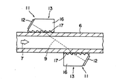
図9は、従来のクランプオン型超音波流量計の一例の構成を示す断面図である。図9に示すクランプオン型超音波流量計は、伝搬時間差式の流量計である。クランプオン型超音波流量計は、一対の超音波送受信器1a及び1bから構成される。超音波送受信器1aは、超音波振動子2aと楔形超音波伝搬材3aから構成される。楔型超音波伝搬材3aは、底面4aと底面4aに対して鋭角をなす斜面5aを備えている。超音波振動子2aは、楔型超音波伝搬材3aの斜面5aに装着される。そして、超音波振動子2aの楔型超音波伝搬材側の面及びその逆側の面には、超音波振動子2aに電圧を印加するために電極とリード線(図示は略する)が備えられている。同様に、超音波送受信器1bは、超音波振動子2bが、楔型超音波伝搬材3bの斜面5bに装着された構成を有する。
【0004】
超音波振動子2a及び2bのそれぞれは、電極に電圧が印加されると超音波を楔形超音波伝搬材に付与(送信)し、逆に超音波が付与(受信)されると電極に電圧を生じる。従って、超音波振動子が備えられた超音波送受信器1a及び1bのそれぞれは、超音波の送信器でもあり、受信器でもある。そして、超音波送受信器1a及び1bは、管状体6の内部を移動する流体7の移動方向(図9に記入した矢印7の示す方向)に対して斜めに超音波を送受信するように、管状体6の外周面上に装着される。図9に記入した破線9は、超音波の伝搬経路の一例を意味する。
【0005】
管状体6の内部を移動する流体7の流量は、以下の様にして測定される。先ず、超音波送受信器1aの超音波振動子2aに電圧パルスを印加して、超音波を送信する。超音波は、図9に示す破線9の方向に沿って、楔型超音波伝搬材3a、管状体6、流体7、管状体6、そして楔形超音波伝搬材3bの順に伝搬して、超音波送受信器1bの超音波振動子2bにより受信されて電圧信号が出力される。超音波送受信器1aが超音波の送信を開始してから、超音波送受信器1bが超音波を受信するまでの時間(T1 )を検出する。次に、超音波送受信器1bの超音波振動子2bに電圧パルスを印加して、前記とは逆の伝搬経路で超音波を伝搬させ、超音波送受信器1aの超音波振動子2aにより超音波を受信する。超音波送受信器1bが超音波の送信を開始してから、超音波送受信器1aが超音波を受信するまでの時間(T2 )を検出する。
【0006】
超音波が、超音波送受信器1a及び1bの間を伝搬するのに要する時間(T1 及びT2 )は、超音波の伝搬する方向(図9に示す矢印9a及び9bの示す方向)により異なる値となる。超音波送受信器1aから超音波送受信器1bに(矢印9aが示す方向に)向かう超音波は、いわば流体の流れに乗って流体中を伝搬するので、伝搬時間(T1 )は、流体が静止している場合と比べると短い値となる。一方、超音波送受信器1bから超音波送受信器1aに(矢印9bが示す方向に)向かう超音波は、流体の流れに逆らって流体中を伝搬するので、伝搬時間(T2 )は、流体が静止している場合と比べると長い値となる。これらの伝搬時間の差(T2 −T1 )は、流体7の移動速度と相関があり、この伝搬時間の差から流体7の移動速度が算出される。そして、得られた流体の移動速度、管状体6の流水断面積などから流体7の流量を算出することができる。
【0007】
このようなクランプオン型超音波流量計には、流体に非接触で流量の測定が可能であるという大きな利点があるところから、その利点を生かすために、流量計の測定感度をさらに高める検討がされている。
【0008】
クランプオン型超音波流量計の測定感度を高める手段の一つとして、流体中における超音波の伝搬距離を長くすることが挙げられる。流体中における超音波の伝搬距離を長く設定できると、小さな流量に対しても、大きな伝搬時間から流量の測定ができるために、流量計の測定感度を高くすることができる。
【0009】
超音波振動子から送信された超音波は、楔形超音波伝搬材、管状体、そして流体の順に伝搬する。超音波は、スネルの法則により、楔形超音波伝搬材と管状体の界面において、両者の音波伝搬速度の比に基づき屈折する。同様に、超音波は、管状体と流体の界面において、両者の音波伝搬速度の比に基づき屈折する。超音波の伝搬経路は、楔形超音波伝搬材、管状体、および流体の音波伝搬速度の値を用い、前記の各界面における超音波の入射角と屈折角を、スネルの法則を用いて計算することにより定まる。この様な伝搬経路の計算により、流体中における超音波の伝搬距離を大きくするための、適切な楔形超音波伝搬材の音波伝搬速度と、管状体外周面における超音波の入射角が定まる。詳しくは後に記載するが、楔形超音波伝搬材は、管状体の音波伝搬速度の値にほぼ等しい音波伝搬速度を示す材料から形成することが好ましい。
【0010】
【発明が解決しようとする課題】
従来から用いられているクランプオン型超音波流量計では、管状体とほぼ等しい音波伝搬速度を示す材料から楔形超音波伝搬材を形成した場合でも、超音波流量計の測定感度は、ある程度以上には高くすることはできない。これは、超音波振動子から楔形超音波伝搬材に付与された超音波が、楔形超音波伝搬材の内部を伝搬する際に減衰してしまうためである。一般に、流体を移動する管状体を形成する材料としては、鉄、ステンレススチール、塩化ビニル樹脂、およびフッ素樹脂などが用いられている。このうち、フッ素樹脂は、特に超音波を減衰させ易い材料として知られている。フッ素樹脂製管状体の内部を移動する流体の流量を測定するために、楔形超音波伝搬材をフッ素樹脂から形成しても、流量計の測定感度を充分高くすることは困難である。
【0011】
楔形超音波伝搬材の内部における超音波の減衰は、縦波として伝搬する超音波の一部が横波となったり、超音波が熱エネルギーに変換されたりするために生じると考えられる。超音波の減衰の程度は、楔形超音波伝搬材を形成する材料の種類により個別に定まる。従って、楔形超音波伝搬材を、管状体とほぼ等しい音波伝搬速度を示し、且つ超音波が減衰し難い材料から形成することにより、流量計の測定感度を高くすることができる。ところが、本発明者の検討によると、材料選定を工夫しても、充分に測定感度の高いクランプオン型超音波流量計を得ることは困難であることが判明した。
本発明の目的は、測定感度の高いクランプオン型超音波流量計を提供することにある。
【0012】
【課題を解決するための手段】
本発明者は、楔形超音波伝搬材を、互いに異なる材料からなる第一超音波伝搬材および第二超音波伝搬材の二つの伝搬材から構成することにより、測定感度の高い流量計を提供できることを見出した。
【0013】
本発明は、超音波振動子が、底面と該底面に対して鋭角をなす少なくとも一つの斜面を備えた楔型超音波伝搬材の該斜面に装着されてなる超音波送受信器であって、該超音波伝搬材が、超音波振動子から超音波伝搬材に付与された超音波が、超音波振動子装着斜面に対して垂直な方向に伝搬するように構成され、かつ底面に超音波振動子装着斜面と平行な複数の表面が整列形成された第一超音波伝搬材、及び第一超音波伝搬材の底面に密着状態で付設された弾性シート製の第二超音波伝搬材を含むことを特徴とする超音波送受信器にある。本発明の超音波送受信器の好ましい態様は、下記の通りである。
【0014】
(1)第一超音波伝搬材が、樹脂材料シート中に複数本の高弾性繊維がシート平面に沿って平行に整列配置された構成の繊維強化樹脂シートが複数枚積層一体化された構成にある。
(2)第一超音波伝搬材が、複数枚の繊維強化樹脂シートが、隣接する各シート内の高弾性繊維の整列方向が互いに直角をなすように交互に積層一体化された構成をなしている。
(3)繊維強化樹脂シートの高弾性繊維の長さ方向の引張弾性率が50GPa以上である。
【0015】
(4)繊維強化樹脂シートの高弾性繊維が炭素繊維である。
(5)第二超音波伝搬材の、第一超音波伝搬材に接する表面とは逆側の表面が凹状に湾曲している。
(6)第二超音波伝搬材が1000〜2000m/秒の音波伝搬速度を示す弾性材料から形成されている。
(7)第二超音波伝搬材の音波伝搬速度が第一超音波伝搬材の音波伝搬速度よりも小さくされている。
(8)第二超音波伝搬材が、ポリウレタンゲルから形成されている。
【0016】
本発明はまた、前記の超音波送受信器が一対、底面に開口を有する細長い形状のケースに、各超音波送受信器の超音波振動子が装着された斜面が互いに対向しないような位置関係で収容固定されてなる、クランプオン型超音波流量計にもある。
【0017】
本発明はまた、前記の超音波送受信器が一対、底面に開口を有する細長い形状のケースに、各超音波送受信器の超音波振動子が装着された斜面が互いに対向しないような位置関係にあり、かつ超音波送受信器間の距離を任意に変えることができるように収容されてなるクランプオン型超音波流量計にもある。
【0018】
前記の二種類の本発明のクランプオン型超音波流量計の好ましい態様は、以下の通りである。
(1)第二超音波伝搬材の音波伝搬速度よりも小さな音波伝搬速度を示す樹脂材料製の管状体の内部を移動する流体の流量測定用である。
(2)フッ素樹脂製管状体の内部を移動する流体の流量測定用である。
【0019】
本発明はまた、内部を流体が移動する管状体に前記のクランプオン型超音波流量計が、そのケースの長さ方向と管状体の長さ方向とが一致するように装着固定されてなる流量測定構造体にもある。本発明の流量測定構造体は、音波伝搬速度の小さい既設の配管に対して好ましく用いることができる。このような場合、本発明の流量測定構造体の管状体としては、既設の配管を形成する材料と対応させて、第二超音波伝搬材の音波伝搬速度よりも小さな音波伝搬速度を示す樹脂材料製の管状体、2000m/秒より小さな音波伝搬速度を示す樹脂製の管状体、もしくはフッ素樹脂製の管状体を好ましく用いることができる。
【0020】
【発明の実施の形態】
まず最初に、超音波送受信器の超音波振動子により送信された超音波の伝搬経路について、添付の図面を用いて説明する。図10は、管状体の外周面と内周面のそれぞれにおける、超音波の伝搬経路を説明する図である。図10において、超音波振動子(図示は略する)から送信された超音波は、楔形超音波伝搬材3、管状体6、そして流体7の順に伝搬する。破線9は、楔形超音波伝搬材3と管状体6の界面、および管状体6と流体7の界面のそれぞれにおける超音波の伝搬経路の一例を示す。
【0021】
[管状体の内周面における超音波の伝搬]
図10に示すように、流体中における超音波の伝搬距離は、管状体の内周面における超音波の屈折角β2 の値が大きい程長くなることがわかる。管状体の内周面においては、スネルの法則により下記式(I)で示される関係が成立する。
(I)sinα2 /sinβ2 =C2 /C3
式(I)において、C2 は、管状体の音波伝搬速度を表し;C3 は、流体の音波伝搬速度を表し;α2 は、音波の入射角を表し;そしてβ2 は、音波の屈折角を表す。
【0022】
上記式(I)からわかるように、管状体の音波伝搬速度C2 と流体の音波伝搬速度C3 の比により、入射角α2 と屈折角β2 の上限値が定まる。入射角α2 と屈折角β2 の上限値は、管状体の音波伝搬速度C2 と流体の音波伝搬速C3 の大小関係により、下記の様に定まる。
【0023】
[C2 <C3 の場合の、管状体の内周面における超音波の伝搬]
管状体の音波伝搬速度C2 が流体の音波伝搬速C3 より小さい場合には、ある入射角(臨界角)以上の値で、超音波が管状体の内周面で全反射をしてしまい、流体中に超音波を伝搬させることができない。臨界角α2maxは、式(I)のβ2 を90度とすることにより、下記式(II)で示される。
(II)α2max=sin-1(C2 /C3 ):(但し、C2 <C3 )
従って、管状体の内周面における超音波の入射角α2 を、全反射が生じない程度にα2maxに近い値とすることで、流体中における超音波の伝搬距離を最大にすることができる。従って、管状体の外周面における屈折角β1 が、α2maxに近い値となるよう、入射角α1 を設定することにより、流体中における超音波伝搬距離(流量計の測定感度に対応する)を最大に設定できる。
【0024】
[C2 >C3 の場合の、管状体の内周面における超音波の伝搬]
一方、管状体の音波伝搬速度C2 が流体の音波伝搬速C3 のより大きい場合には、管状体の内周面における超音波の全反射は生じないが、入射角α2 を90度にしても屈折角β2 は90度にはならずに、ある最大値(β2max)を示す。屈折角の最大値βmaxは、式(I)のα2 を90度とすることにより、下記式(III)で示される。
(III)β2max=sin-1(C3 /C2 ):(但し、C2 >C3 )
従って、管状体の内周面における超音波の入射角α2 をどんなに大きな値に設定しても、流体中における超音波の伝搬距離は、β2maxにより定まる伝搬距離以上にすることはできない。この場合、管状体の外周面における屈折角β1 を極力大きな値に設置することにより、流体中における超音波伝搬距離を、β2maxで定まる最大の距離に設定することができる。
【0025】
[管状体の外周面における超音波の伝搬]
一方、スネルの法則は、管状体の外周面においても成立する。管状体の外周面における、超音波の入射角α1 と屈折角β1 には、下記式(IV)及び(V)で示される上限値が存在する。
(IV)α1max=sin-1(C1 /C2 ):(但し、C1 <C2 )
(V)β1max=sin-1(C2 /C1 ):(但し、C1 >C2 )
式(IV)及び(V)において、C1 は、楔形超音波伝搬材の音波伝搬速度を表し;α1maxは、管状体の外周面における入射角α1 の最大値(臨界角)を表し;そしてβ1maxは、管状体の外周面における屈折角β1 の最大値を表す。
【0026】
[C1 <C2 の場合の、管状体の外周面における超音波の伝搬]
楔形超音波伝搬材の音波伝搬速度C1 が、管状体の音波伝搬速度C2 より小さい場合(式(IV)の関係が成立する場合)には、入射角がα1max以下となる範囲において、超音波の送信方向(楔形超音波伝搬材の斜面の角度)を調節することにより、屈折角β1 を任意の値に設定することができる。従って、流体内における超音波の伝搬距離が最大となるように、管状体の内周面に超音波を伝搬させることができる。但し、C1 とC2 の値の差が大きいほど、α1maxが小さくなるために、屈折角β1 を精度良く設定することが難しくなる。従って、楔形超音波伝搬材の音波伝搬速度C1 と、管状体の音波伝搬速度C2 の値の差は小さい方が好ましい。
【0027】
[C1 >C2 の場合の、管状体の外周面における超音波の伝搬]
一方、楔形超音波伝搬材の音波伝搬速度C1 が、管状体の音波伝搬速度C2 より大きい場合(式(V)の関係が成立する場合)には、入射角α1 を極力大きく設定しても、屈折角β1の最大値β1maxが存在する。
【0028】
従って、管状体の内周面において式(II)の関係が成立する場合に、管状体の外周面における屈折角の最大値β1maxが、管状体の内周面における臨界角α2maxより小さい値であると、流体中における超音波の伝搬距離を最大とするように入射角α2 を設定できない(入射角α2 を、α2maxに近い値に設計できない)ために、高感度の流量計を設計することが難しい。
【0029】
一方、管状体の内周面において式(III)の関係が成立する場合にも、入射角α2 を、β1maxの値にまでしか大きく設定できない。このため、流体中における超音波の伝搬距離を最大とするように入射角α2 を設定できないので、高感度の流量計を設計することが難しい。
【0030】
但し、式(V)によりβ1maxが定まる場合にも、C1 とC2 の値の差が小さいほど、β1maxが大きな値となるため、管状体の内周面において式(I)または(II)の関係が成立する場合にも、高感度の流量計を設計し易くなる。従って、楔形超音波伝搬材の音波伝搬速度C1 と、管状体の音波伝搬速度C2 の値の差は小さい方が好ましい。
【0031】
以上のように、楔形超音波伝搬材を形成する材料としては、管状体を形成する材料の音波伝搬速度を考慮して、適切な音波伝搬速度を示す材料(好ましくは、管状体の音波伝搬速度に近い値の音波伝搬速度を示す材料)が選定される。また、楔形超音波伝搬材と管状体の音波伝搬速度の差の値が大きくなるにつれ、両者の音響インピーダンスの差により、管状体の外周面において超音波の反射量が大くなる。従って、通常は、楔形超音波伝搬材を形成する材料としては、管状体の音波伝搬速度にほぼ等しい値を示す材料が選定される。即ち、簡便には、楔形超音波伝搬材を、管状体と同一の材料から形成すればよい。そして、流体中における超音波の伝搬距離が最大(即ち、β2 が最大)となるように、管状体外周面における超音波の入斜角α1 (即ち、楔形超音波伝搬材の底面と斜面のなす角度)を設定することにより、測定感度の高い流量計が得られる。なお、音響インピーダンスは、音波の伝搬媒体となる材料の、音波伝搬速度と密度の積により定まる。
【0032】
ところが、超音波振動子から送信された超音波は、楔形超音波伝搬材を形成する材料の内部を伝搬する際に、材料の種類により程度の差はあるものの減衰してしまう。例えば、管状体を形成する材料の一つであるフッ素樹脂は、超音波を減衰させ易い材料として知られている。このようなフッ素樹脂製の管状体の内部を移動する流量を測定するために、楔形超音波伝搬材をフッ素樹脂から形成しても、超音波が楔形超音波伝搬材を伝搬する間に大きく減衰するために、流量計の測定感度を高くすることができない。楔形超音波伝搬材に必要とされる適切な音波伝搬速度の値は、上記のようにスネルの法則を用いて計算は可能である。しかし、計算された音波伝搬速度に近い値の音波伝搬速度を示し、且つ超音波を伝搬し易い材料の選定は困難である。
【0033】
なお、流量測定の際には、楔形超音波伝搬材と管状体の間に、超音波伝搬経路から空気を排除するためのグリースなどの接触媒質が存在するが、上記においてはこれらを無視して簡略に説明をした。実際の流量計は、このような接触媒質の存在も考慮して、楔形超音波伝搬材を形成する材料を選定し、上記の様にスネルの法則を用いて超音波の伝搬経路を設定(即ち、管状体の外周面における超音波の入射角を設定)することにより設計される。
【0034】
次に、本発明の超音波送受信器を、添付の図面を用いて説明する。図1は、本発明の超音波送受信器の構成を示す斜視図である。図1に示す本発明の超音波送受信器11は、超音波振動子12と楔形超音波伝搬材13から構成される。楔形超音波伝搬材13は、底面14と底面14に対して鋭角をなす斜面15を備えている。超音波振動子12は、楔形超音波伝搬材13の斜面15に装着される。そして、超音波振動子12の楔形超音波伝搬材側の面及びその逆側の面には、超音波振動子に電圧を印加するために電極とリード線(図示は略する)が備えられている。
【0035】
楔形超音波伝搬材13は、第一超音波伝搬材16及び第二超音波伝搬材17から構成される。第二超音波伝搬材は17は、弾性材料もしくは可塑性材料から形成され、第一超音波伝搬材16の底面18に密着状態で付設される。そして、超音波振動子12から楔形超音波伝搬材13に付与された超音波が、超音波振動子装着斜面15に対して垂直な方向に伝搬するように、第一超音波伝搬材16の底面18には、超音波振動子装着斜面15と平行な複数の表面19が整列形成されている。
【0036】
超音波振動子12により送信された超音波は、超音波振動子装着斜面15と平行な複数の表面19に垂直に入射する。従って、第一超音波伝搬材16と第二超音波伝搬材17との界面における超音波の屈折や反射が防止される。超音波が、前記の界面において屈折して、超音波振動子装着斜面15に垂直な方向以外に伝播すると、受信される超音波の強度が低下するために測定感度が低下する。また、超音波を超音波振動子装着斜面15と平行な複数の表面19に垂直に入射させることにより、第一超音波伝搬材16と第二超音波伝搬材17との音響インピーダンスの差により両者の界面において生じる超音波の反射量を最低にすることができる。このため、第一超音波伝搬材16から第二超音波伝搬材17に超音波を十分伝搬させることができる。
【0037】
そして、楔形超音波伝搬材13の第二超音波伝搬材17を、スネルの法則を用いた計算により得られる適切な音波伝搬速度を示す材料から形成する。一方、第一超音波伝搬材16は、超音波の減衰量が小さい材料から形成する。超音波が材料の内部を伝搬する際の減衰量の大小は、例えば、二種類の材料を円柱状に加工し、その両端のそれぞれに超音波送受信器を装着して超音波を送受信し、得られた受信信号の大きさを比べることにより簡単に測定することができる。
【0038】
楔形超音波伝搬材13の内部における超音波の伝搬経路において、超音波が、適切な音波伝搬速度を示す材料から形成された第二超音波伝搬材17を伝搬する距離は、従来のように楔形超音波伝搬材の全体を同じ材料から形成する場合よりも短い。このため、第二超音波伝搬材17を形成する材料が超音波を減衰させ易い材料であっても、超音波がその材料中を伝搬する距離が短いために、従来よりも楔形超音波伝搬材の内部における超音波の減衰量を小さくすることができる。
【0039】
第一超音波伝搬材16を形成する材料としては、超音波の減衰量が小さい材料を用いれば特に制限はない。例えば、従来の楔型超音波伝搬材を形成する材料から第二超音波伝搬材17を形成し、第二超音波伝搬材より超音波の減衰量が相対的に小さい材料から第一超音波伝搬材16を形成することにより、容易に流量計の測定感度を高くすることができる。
【0040】
このように、楔形超音波伝搬材を上記のような構成とすることにより、第一超音波伝搬材については、超音波の減衰量のみに注目して材料の選定ができ、一方、第二超音波伝搬材については、音波伝搬速度のみに注目して材料の選定ができる。従って楔形超音波伝搬材を形成する材料の選定が容易となり、測定感度の高い流量計を容易に得ることができる。
【0041】
また、第一超音波伝搬材を形成する材料としては、繊維強化樹脂材を用いることが好ましい。本発明者の研究により、繊維強化樹脂材が、特に、繊維の長さ方向に垂直な方向に伝搬する超音波を減衰させ難い材料であることがわかった。繊維強化樹脂材は、樹脂材料シート中に複数本の高弾性繊維がシート平面に沿って平行に整列配置された構成の繊維強化樹脂シートが複数枚積層一体化された構成を有する。一般に、超音波は、媒質中を縦波として伝搬するが、媒質が固体の場合には、その一部が横波となり減衰することが知られている。繊維強化樹脂材が、繊維の長さ方向に垂直な方向に伝搬する超音波を減衰させ難い理由は、繊維強化樹脂材の内部に、振動を抑制する高弾性繊維が間欠的に整列配置しているために、繊維強化樹脂の内部を伝搬する横波が励起され難いためと推測される。
【0042】
第一超音波伝搬材16を繊維強化樹脂材から形成する場合、超音波振動子12から楔形超音波伝搬材13に付与された超音波が、超音波振動子装着斜面15に対して垂直な方向に伝搬するように、高弾性繊維20の長さ方向は、斜面15(超音波振動子12の振動面)と平行な方向に整列配置させる。このように高弾性繊維を整列配置することにより、超音波振動子の、高弾性繊維の長さ方向に沿った振動の励起が抑えられ、繊維に垂直な方向に指向性に優れる超音波が送信できる。超音波振動子と繊維強化樹脂材の積層体における、超音波の伝搬方向の制御については、特開平7−284198号公報に詳しく記載されている。第一超音波伝搬材16は、市販の繊維強化樹脂材を切削加工して形成することができる。
【0043】
高弾性繊維20が整列配置する方向は、楔形超音波伝搬材13の斜面(超音波振動子の振動面)に平行であれば特に制限は無いが、製造のし易さ、コストの面で、前記の斜面15に平行な、一方向または二方向に整列配置させることが好ましい。
【0044】
楔形超音波伝搬材13の斜面15に平行な一方向のみに高弾性繊維20を整列配置させる場合は、図1に示すように、高弾性繊維20の長さ方向を楔形超音波伝搬材13の底面14に投影した線と、斜面15の法線を前記の底面に投影した線とが平行であることが好ましい。高弾性繊維を斜面15に平行な一方向のみに整列配置した場合、(斜面と平行で)高弾性繊維と直交する方向には、高弾性繊維による制振効果が小さいために、若干の振動の励起を生じてノイズの原因となる場合がある。このような振動の励起があった場合にも、図1に示すように高弾性繊維20を整列配置すると、励起された振動による音波は、伝搬方向が楔形超音波伝搬材13の側面に垂直な方向であるために、管状体6には伝搬し難い。逆に、高弾性繊維を、斜面15と平行で、側面に垂直な一方向に整列配置すると、(斜面と平行で)高弾性繊維と直交する方向に励起された振動による音波は、伝搬方向が、先の場合の繊維の長さ方向と同方向となり、管状体に伝播してノイズとなり、測定感度を低下させる場合がある。
【0045】
楔形超音波伝搬材13の斜面15に平行な二方向に高弾性繊維20を整列配置させる場合は、楔形超音波伝搬材13を、複数枚の繊維強化樹脂シートが、隣接する各シート内の高弾性繊維の整列方向が互いに直交をなすように交互に積層され、一体化された構成とすることが好ましい。
【0046】
超音波振動子の振動面に沿った方向の振動の励起を抑制するため、高弾性繊維20の長さ方向の引張弾性率は、50GPa以上であることが好ましく、100GPa以上であることがより好ましい。高弾性繊維の例としては、炭素繊維、炭化ケイ素繊維、ナイロン繊維、ポリアミド繊維、およびアラミド繊維などが挙げられ、炭素繊維もしくは炭化ケイ素繊維を用いることが好ましい。また、繊維強化樹脂シートの樹脂材料21の例としては、エポキシ樹脂、ナイロン樹脂、ポリイミド樹脂、PEEK(ポリエーテルエーテルケトン)、フェノール樹脂、不飽和ポリエステル樹脂、ポリアミド樹脂、ポリカーボネート樹脂、およびポリアミドイミド樹脂などが挙げられ、エポキシ樹脂を用いることが好ましい。
【0047】
第二超音波伝搬材17は、弾性材料もしくは可塑性材料から形成する。弾性材料もしくは可塑性材料としては、前記のように、管状体を形成する材料の音波伝搬速度を考慮して、適切な音波伝搬速度を示す材料が選択される。そして、弾性材料もしくは可塑性材料の音波伝搬速度の値と、管状体の音波伝搬速度の値の差は小さいほうが好ましい。簡便には、第二超音波伝搬材は、管状体を形成する材料と同一の材料から形成することができる。弾性材料の例としては、金属材料、樹脂材料、およびゲル状の弾性材料などが挙げられる。金属材料の例としては、一般に管状体の形成に用いられる、鉄、ステンレススチールなどの金属材料が挙げられる。樹脂材料の例としては、一般に管状体の形成に用いられる、塩化ビニル樹脂およびフッ素樹脂、そして、従来の楔形超音波伝搬材の形成に用いられる、エポキシ樹脂、アクリル樹脂などが挙げられる。ゲル状の弾性材料には、軟質エラストマーが含まれる。ゲル状の弾性材料の例としては、シリコーンゲル、ポリウレタンゲル、ポリウレタンエラストマーなどが挙げられる。可塑性材料の例としては、グリースが挙げられる。
【0048】
また、楔形超音波伝搬材13の底面14が、管状体6の外周面と密着するように、第二超音波伝搬材17の、第一超音波伝搬材16に接する表面とは逆側の面(楔形超音波伝搬材の底面14)を凹状に加工することも好ましい。ただし、第二超音波伝搬材17を金属や樹脂材料などの弾性材料から形成する場合、前記の面を曲面に加工することは手間がかかるため、第二超音波伝搬材17は、ゲル状の弾性材料もしくは可塑性材料から形成することが好ましい。ゲル状の弾性材料としては、ポリウレタンゲルを用いることが好ましい。可塑性材料としては、グリースを用いることが好ましい。第二超音波伝搬材を、グリースなどの可塑性材料から形成する場合、管状体6に可塑性材料を厚めに塗布して、可塑性材料の上から超音波振動子が備えられた第一超音波伝搬材を押し付けることにより、簡便に超音波送受信器を形成することができる。
【0049】
また、楔形超音波伝搬材13と管状体6との間に空気(隙間)が存在すると、空気の音響インピーダンスが小さいために、超音波が楔型超音波伝搬材と空気の界面で反射してしまうため、楔型超音波伝搬材13と管状体6との隙間には、接触媒質を充填することが好ましい。管状体6の外周面上に接触媒質を塗布してから超音波送受信器11を管状体6に押し付けることで、前記の隙間に接触媒質を充填することができる。このような、超音波の伝搬経路から空気を排除するために用いる接触媒質としては、公知の材料を用いることができる。接触媒質としては、気泡が残りにくい液体またはペースト状の材料が用いられ、一般には、水、油、水ガラス、グリース、ワセリンなどが用いられる。超音波送受信器を管状体に固定して、継続的に流体の流量を測定する場合には、接触媒質としてはグリースを用いることが好ましい。また、接触媒質として液状の高分子材料を用いることもできる。なお、前記の様に、第二超音波伝搬材を可塑性材料から形成する場合には、接触媒質は用いなくてもよい。
【0050】
次に、本発明の超音波送受信器の別の態様について説明する。図2は、本発明の超音波送受信器の別の一例の構成を示す斜視図である。図2に示す超音波送受信器11は、楔形超音波伝搬材13の形状が異なる以外は、図1に示した超音波送受信器と同様の構成である。超音波を、超音波振動子装着斜面に垂直に伝搬させるためには、図1に示した構成の楔型超音波伝搬材の形状で十分であるが、図2に示すように、第一超音波伝搬材16の上側に、水平面を設けることが好ましい。このような水平面に、超音波送受信器を固定するためのボルト穴22を設けることで、超音波送受信器11の管状体6の外周面に対する位置を、ボルトを用いて容易に固定できる。具体的な固定の方法については、後述する。また、このような第一超音波伝搬材16の一例の構成の具体的な寸法(単位:mm)を、図3に記載する。図3において、図(a)は、第一超音波伝搬材16の側面図であり、そして図(b)は、背面図である。
【0051】
前述のように、クランプオン型超音波流量計には、伝搬時間差式、ドップラー式のように多くの種類があり、用いられる超音波送受信器の数も様々である。クランプオン型超音波流量計については、「流量計測AtoZ」(日本計量機器工業連合会編、第8章、1995)に詳しく記載がある。本発明の超音波送受信器は、様々な種類のクランプオン型超音波流量計のいずれにも好ましく用いることができる。図4に、本発明の超音波送受信器を用いたV式のクランプオン型超音波流量計の一例の構成の断面図を、図5に、Z式のクランプオン型超音波流量計の一例の構成の断面図を示す。図4および図5に示すクランプオン型超音波流量計は、いずれも伝搬時間差式の流量計である。Z式、V式とは、流体中での超音波の伝搬経路9の形状から命名されている。V式のクランプオン型超音波流量計は、Z式に比べて、超音波伝搬経路9が長いために測定感度が高く、管状体6を挟んで超音波送受信器を配置する必要がないために設置が容易であるという利点がある。
【0052】
流体の移動に用いられる管状体を形成する材料の例(括弧内に音波伝搬速度の値を示す)としては、ステンレススチール(約5000m/秒)、塩化ビニル樹脂(約2200m/秒)、もしくはフッ素樹脂(約1200m/秒)などが挙げられる。一般に、音波伝搬速度が特に小さい値を示す樹脂材料から形成された管状体に対して、高感度の流量計を設計することは難しい。これは、この様に音波伝搬速度が特に小さい材料が、超音波の減衰量が大きい材料であった場合に、これに変えて、管状体と音波伝搬速度が近い値を示し、且つ超音波の減衰量が小さい楔形超音波伝搬材形成用の材料を探すことが難しいためである。このような、音波伝搬速度が特に小さく、超音波の減衰量が大きい材料には、上記に挙げた例のうちのフッ素樹脂が該当する。
【0053】
本発明の超音波送受信器を用いた流量計は、音波伝搬速度が小さい管状体の内部を流れる流体の流量測定用に好ましく用いることができる。音波伝搬速度が小さい管状体に対しては、第二超音波伝搬材は、1000〜2000m/秒の音波伝搬速度を示す弾性材料もしくは可塑性材料から形成することが好まく、特にポリウレタンゲル(音波伝搬速度:約1400m/秒)またはグリース(音波伝搬速度:約1500m/秒)を用いることが好ましい。また、第二超音波伝搬材の音波伝搬速度が、第一音波伝搬材の音波伝搬速度よりも小さいことが好ましい。第一超音波伝搬材を形成する材料として、例えば、エポキシ樹脂と炭素繊維から構成される繊維強化樹脂材を用いる場合、繊維強化樹脂材の音波伝搬速度の値は、炭素繊維の長さ方向に垂直な方向で、3000m/秒程度である。
【0054】
本発明に従い、第一超音波伝搬材16を繊維強化樹脂材、そして第二超音波伝搬材17をフッ素樹脂から形成することで、フッ素樹脂製の管状体に対しても測定感度の高い流量計が提供できる。また、フッ素樹脂は超音波の減衰量が大きいため、第二超音波伝搬材を、ゲル状の弾性材料から形成することがさらに好ましく、ポリウレタンゲルから形成することが特に好ましい。
【0055】
次に、本発明のクランプオン型超音波流量計について説明する。図6は、本発明のクランプオン型超音波流量計の一例の構成を示す一部切欠き斜視図である。本発明のクランプオン型超音波流量計は、基本的には一対の超音波送受信器と、それぞれの超音波送受信器の管状体に対する位置を固定する手段からなる。図6に示すように、本発明のクランプオン型超音波流量計は、前記の本発明の超音波送受信器が一対(11a及び11b)、底面に開口を有する細長い形状のケース23に、各超音波送受信器の超音波振動子が装着された斜面が互いに対向しないような位置関係で収容固定されてなる。ケース23は、ケース本体24とケース蓋25から構成される。
【0056】
管状体6の寸法(内径および外径)と材質が予めわかれば、超音波送受信器11aと11bの最適な位置関係は算出できるので、超音波送受信器のそれぞれを、ケース蓋25にボルト26を用いて固定する。このように予め一対の超音波送受信器間の位置関係を固定しておくことで、既設の管状体(化学プラントの配管など)にクランプオン型超音波流量計を装着する作業が容易となる。
【0057】
流量計と管状体は、管状体6をケース23と流量計固定材27により挟んで、ケース23と流量計固定材27をねじ28により締め付けることにより、簡便且つ確実に固定することができる。流量計の管状体への固定方法は、前記の方法に限定されず、ゴムバンドなどを用いてケース本体23と管状体6を締め付けて固定してもよい。
【0058】
管状体の寸法(内径および外径)や材質が不明な場合などは、一対の超音波送受信器間の距離を、流量計を管状体に装着する際に設定する必要がある。このため、ケース蓋25に、長穴29を設けるなどして、流量計を、超音波送受信器間の距離を任意に変更できる構成とすることもできる。
【0059】
本発明の超音波流量計は、第二超音波伝搬材の音波伝搬速度よりも小さな音波伝搬速度を示す樹脂材料製の管状体の内部を移動する流体の流量測定用として好ましく用いることができる。また、前記のように、本発明の超音波流量計は、音波伝搬速度が特に小さい(概ね2000/秒以下)値を示す樹脂材料製の管状体の内部を移動する流体の流量測定用として好ましく用いることができ、フッ素樹脂製の管状体の内部を移動する流体の流量測定用として特に好ましく用いることができる。
【0060】
音波伝搬速度が特に小さい値を示す樹脂材料製の管状体の内部を移動する流体の流量を測定する場合には、楔形超音波伝搬材は、繊維強化樹脂材から形成された第一超音波伝搬材、およびポリウレタンゲルから構成された第二超音波伝搬材から構成されることが特に好ましい。この構成の楔形超音波伝搬材の底面と斜面のなす角度(即ち、管状体の外周の表面における超音波の入射角)は、40乃至70度の範囲にあることが好ましい。
【0061】
繊維強化樹脂材とポリウレタンゲルから構成された超音波伝搬材を用いた流量計を、ステンレススチール製管状体もしくはポリ塩化ビニル樹脂製の管状体の内部を移動する流体の流量測定用とする場合には、前記のようにスネルの法則を用いて、流体中における超音波の伝搬距離が最大となるように、楔形超音波伝搬材の底面と斜面のなす角度を設定すればよい。具体的には、ステンレススチール製の管状体に対しては、楔形超音波伝搬材の底面と斜面のなす角度を、5乃至25度の範囲に設定することが好ましい。また、ポリ塩化ビニル樹脂製の管状体に対しては、楔形超音波伝搬材の底面と斜面のなす角度を、25乃至45度の範囲に設定することが好ましい。
【0062】
また、化学プラントなどにおける既設の配管が取り外し可能である場合には、予め管状体とクランプオン型超音波流量計とを一体化させた流量測定構造体を用いることもできる。このような構成とすることで、予め超音波送受信器の位置関係を精密に調整した(管状体とクランプオン型超音波流量計が一体となった)流量測定構造体と、既設の配管を交換するのみで、直ちに流量の測定が可能となる。このような本発明の流量測定構造体は、図6に示すように、ケース23の長さ方向と管状体6を、ケースの長手方向と管状体の長さ方向とが一致するように固定することで得られる。このように固定するためには、ケース23と流量計固定材27により管状体6を挟み、ねじ28などの固定手段により、ケース23と固定材27とを締め付け固定すればよい。本発明の流量測定構造体は、音波伝搬速度の小さい既設の配管に対して好ましく用いることができる。このような場合、本発明の流量測定構造体の管状体6としては、既設の配管を形成する材料と対応させて、第二超音波伝搬材の音波伝搬速度よりも小さな音波伝搬速度を示す樹脂材料製の管状体、2000m/秒より小さな音波伝搬速度を示す樹脂製の管状体、もしくはフッ素樹脂製の管状体を好ましく用いることができる。
【0063】
【発明の効果】
本発明の超音波送受信器は、楔形超音波伝搬材を形成する材料の選定が容易である。そして、本発明の超音波送受信器においては、楔形超音波伝搬材の内部における超音波の減衰量が小さい。このため、本発明の超音波送受信器を用いることにより、高感度のクランプオン型超音波流量計を提供することができる。そして本発明の超音波送受信器を一対用いて構成されるクランプオン型超音波流量計は、超音波送受信器の位置関係の設定が容易であり、流量計を簡単に管状体に装着できる。本発明のクランプオン型超音波流量計は、音波伝搬速度の小さい管状体(特にフッ素樹脂製の管状体)の内部を流れる流体の流量測定用として好ましく用いることができる。また、管状体とクランプオン型超音波流量計とを一体化した本発明の流量測定構造体を用いることにより、化学プラントなどにおける既設の配管と、流量測定構造体を交換するのみで高感度の流量測定を行うことができる。
【0064】
【実施例】
[比較例1]
外径1インチのPTFE(ポリテトラフルオロエチレン)製の管状体に水を流し、市販のクランプオン型超音波流量計(東京計装(株)製)を用いて、超音波の送受信を行った。V法により超音波が送受信されるよう、一対の超音波送受信器を、管状体の表面にグリースを介して配置した。送信側の超音波送受信器の超音波振動子に電圧パルス(パルス幅0.5μs、パルス高さ30V)を印加して超音波を送信し、受信側の超音波送受信器により超音波を受信した。受信側の超音波送受信器において得られた電圧波形を、図7に示す。図7の電圧波形において、横軸は時間、そして縦軸は電圧を表す。得られた電圧波形の最大の振幅は、2.02Vであった。
【0065】
[実施例1]
先ず、エポキシ樹脂と、炭素繊維(繊維の長さ方向の引張弾性率240GPa)から構成された繊維強化樹脂材を切削加工して、図2に示す形状の第一超音波伝搬材を作製した。次に、二液硬化型のポリウレタンゲルを型枠に流し込んだ後に常温硬化させて、図2に示す形状の第二超音波伝搬材を作製した。第二超音波伝搬材の第一超音波伝搬材に接する面とは逆の面は、管状体の外周面と密着するように凹状に湾曲した形状とした。得られた第一超音波伝搬材と第二超音波伝搬材を貼り合わせて楔形超音波伝搬材を作製した。そして楔形超音波伝搬材の斜面に、ジルコン酸チタン酸鉛系の市販の超音波振動子(直径10mm、厚さ1mm)を装着した。この様にして、図2に示す構成の超音波送受信器を作製した。
【0066】
繊維強化樹脂材の高弾性繊維は、図2に示すように楔形超音波伝搬材の斜面(超音波振動子の振動面)に平行な一方向に整列配置させた。また、楔形超音波伝搬材の底面と斜面のなす角度(即ち管状体の外周面における超音波の入射角)は、60度であった。
【0067】
作製した超音波送受信器を一対用いる以外は比較例1と同様にして、超音波の送受信を行った。受信側の超音波送受信器で得られた電圧波形を、図8に示す。図8の電圧波形において、横軸は時間、そして縦軸は電圧を表す。得られた電圧波形の最大の振幅は、2.94Vであった。
【0068】
従って、送信側の超音波振動子に同じ電圧パルスを印加して超音波を送信した場合、受信側の超音波送受信器の超音波振動子から出力される電圧値は、従来の流量計の1.4倍以上であり、本発明の超音波送受信器を用いたクランプオン型超音波流量計の測定感度は非常に高いことがわかる。
【図面の簡単な説明】
【図1】本発明の超音波送受信器の一例の構成を示す斜視図である。
【図2】本発明の超音波送受信器の別の一例の構成を示す斜視図である。
【図3】図2に示す楔型超音波伝搬材の一例の構成の寸法を示す図である。
【図4】本発明の超音波送受信器を用いたZ式のクランプオン型超音波流量計の一例の構成を示す断面図である。
【図5】本発明の超音波送受信器を用いたV式のクランプオン型超音波流量計の一例の構成を示す断面図である
【図6】本発明のクランプオン型超音波流量計の一例の構成を示す一部切欠き斜視図である。
【図7】比較例1において、受信側の超音波送受信器から出力された電圧波形を示す図である。
【図8】実施例1において、受信側の超音波送受信器から出力された電圧波形を示す図である。
【図9】従来のクランプオン型超音波流量計の一例の構成を示す断面図である。
【図10】管状体の外周面及び内周面のそれぞれにおける超音波の伝搬経路を説明する図である。
【符号の説明】
1、1a、1b 超音波送受信器
2、2a、2b 超音波振動子
3、3a、3b 楔形超音波伝搬材
4、4a、4b 底面
5、5a、5b 斜面
6 管状体
7 流体
9 超音波の伝搬経路の例
9a、9b 超音波の伝搬方向を示す矢印
11、11a、11b 超音波送受信器
12、12a、12b 超音波振動子
13、13a、13b 楔形超音波伝搬材
14 楔形超音波伝搬材の底面
15 斜面
16 第一超音波伝搬材
17 第二超音波伝搬材
18 第一超音波伝搬材の底面
19 楔形超音波伝搬材の斜面に平行な面
20 高弾性繊維
21 樹脂
22 ボルト穴
23 ケース
24 ケース本体
25 ケース蓋
26 ボルト
27 流量計固定材
28 ねじ
29 長穴
30 リード線
31 ねじ[0001]
BACKGROUND OF THE INVENTION
The present invention relates to a clamp-on type ultrasonic flow meter.
[0002]
[Prior art]
The clamp-on type ultrasonic flowmeter is a flowmeter that is attached to a part of the outer peripheral surface of a tubular body and measures the flow rate of a fluid that moves inside the tubular body from the outside of the tubular body. The clamp-on type ultrasonic flowmeter can be mainly classified into a propagation time difference type and a Doppler type. The propagation time difference formula reciprocates the ultrasonic wave in a path that crosses the fluid moving inside the tubular body diagonally, and the difference in time required for the ultrasonic wave to propagate in each of the forward path and the return path This is a method for measuring the flow rate. On the other hand, the Doppler method is a method of measuring the flow rate of fluid from the moving speed of suspended particles, etc., assuming that suspended particles and bubbles contained in the fluid move at the same speed as the fluid. The moving speed of the suspended particles or the like is measured by detecting the frequency of the ultrasonic waves by transmitting ultrasonic waves into the fluid and changing the frequency of the ultrasonic waves reflected by the suspended particles or the like due to the Doppler effect.
[0003]
FIG. 9 is a cross-sectional view showing a configuration of an example of a conventional clamp-on type ultrasonic flowmeter. The clamp-on type ultrasonic flow meter shown in FIG. 9 is a propagation time difference type flow meter. The clamp-on type ultrasonic flowmeter includes a pair of ultrasonic transceivers 1a and 1b. The ultrasonic transceiver 1a includes an ultrasonic transducer 2a and a wedge-shaped
[0004]
Each of the
[0005]
The flow rate of the
[0006]
The time required for the ultrasonic wave to propagate between the ultrasonic transceivers 1a and 1b (T1And T2) Has different values depending on the direction in which the ultrasonic waves propagate (directions indicated by
[0007]
Since such a clamp-on type ultrasonic flowmeter has the great advantage of being able to measure the flow rate without contact with the fluid, in order to take advantage of this advantage, studies have been made to further increase the measurement sensitivity of the flowmeter. Has been.
[0008]
One means for increasing the measurement sensitivity of a clamp-on type ultrasonic flowmeter is to increase the propagation distance of ultrasonic waves in a fluid. If the propagation distance of the ultrasonic wave in the fluid can be set long, the flow rate can be measured from a large propagation time even for a small flow rate, so that the measurement sensitivity of the flow meter can be increased.
[0009]
The ultrasonic wave transmitted from the ultrasonic transducer propagates in the order of the wedge-shaped ultrasonic wave propagation material, the tubular body, and the fluid. The ultrasonic wave is refracted at the interface between the wedge-shaped ultrasonic wave propagation material and the tubular body based on the ratio of the sound wave propagation speeds of the two according to Snell's law. Similarly, ultrasonic waves are refracted at the interface between the tubular body and the fluid based on the ratio of the sound wave propagation speeds of the two. The ultrasonic propagation path uses the value of the acoustic wave propagation velocity of the wedge-shaped ultrasonic wave propagation material, the tubular body, and the fluid, and calculates the incident angle and the refraction angle of the ultrasonic wave at each interface using Snell's law. It is determined by that. By calculating the propagation path like this, the sound wave propagation speed of an appropriate wedge-shaped ultrasonic wave propagation material for increasing the propagation distance of the ultrasonic wave in the fluid and the incident angle of the ultrasonic wave on the outer peripheral surface of the tubular body are determined. As will be described in detail later, the wedge-shaped ultrasonic wave propagation material is preferably formed from a material that exhibits a sound wave propagation velocity substantially equal to the value of the sound wave propagation velocity of the tubular body.
[0010]
[Problems to be solved by the invention]
In the conventional clamp-on type ultrasonic flowmeter, even when a wedge-shaped ultrasonic wave propagation material is formed from a material that has a sound propagation velocity substantially equal to that of a tubular body, the measurement sensitivity of the ultrasonic flowmeter exceeds a certain level. Can't be high. This is because the ultrasonic wave applied from the ultrasonic transducer to the wedge-shaped ultrasonic wave propagation material is attenuated when propagating through the inside of the wedge-shaped ultrasonic wave propagation material. Generally, iron, stainless steel, vinyl chloride resin, fluororesin, or the like is used as a material for forming a tubular body that moves a fluid. Among these, a fluororesin is known as a material that easily attenuates ultrasonic waves. Even if the wedge-shaped ultrasonic wave propagation material is made of fluororesin in order to measure the flow rate of the fluid moving inside the fluororesin tubular body, it is difficult to sufficiently increase the measurement sensitivity of the flowmeter.
[0011]
It is considered that the attenuation of the ultrasonic wave inside the wedge-shaped ultrasonic wave propagation material occurs because a part of the ultrasonic wave propagating as a longitudinal wave becomes a transverse wave or the ultrasonic wave is converted into thermal energy. The degree of attenuation of the ultrasonic wave is determined individually depending on the type of material forming the wedge-shaped ultrasonic wave propagation material. Therefore, the measurement sensitivity of the flow meter can be increased by forming the wedge-shaped ultrasonic wave propagation material from a material that exhibits a sound wave propagation speed substantially equal to that of the tubular body and is difficult to attenuate the ultrasonic wave. However, according to the study of the present inventor, it has been found that it is difficult to obtain a clamp-on type ultrasonic flowmeter with sufficiently high measurement sensitivity even if the material selection is devised.
An object of the present invention is to provide a clamp-on type ultrasonic flowmeter having high measurement sensitivity.
[0012]
[Means for Solving the Problems]
The inventor can provide a flowmeter with high measurement sensitivity by configuring the wedge-shaped ultrasonic wave propagation material from two propagation materials of a first ultrasonic wave propagation material and a second ultrasonic wave propagation material made of different materials. I found.
[0013]
The present invention is an ultrasonic transmitter / receiver in which an ultrasonic transducer is mounted on the inclined surface of a wedge-shaped ultrasonic wave propagation material having a bottom surface and at least one inclined surface that forms an acute angle with the bottom surface, The ultrasonic wave propagating material is configured so that the ultrasonic wave applied from the ultrasonic vibrator to the ultrasonic wave propagating material propagates in a direction perpendicular to the ultrasonic transducer mounting slope, and the ultrasonic wave vibrator is formed on the bottom surface. Including a first ultrasonic wave propagation material in which a plurality of surfaces parallel to the mounting slope are aligned and a second ultrasonic wave propagation material made of an elastic sheet attached in close contact with the bottom surface of the first ultrasonic wave propagation material. It is in the characteristic ultrasonic transceiver. Preferred embodiments of the ultrasonic transceiver of the present invention are as follows.
[0014]
(1) The first ultrasonic wave propagating material has a configuration in which a plurality of fiber reinforced resin sheets having a configuration in which a plurality of high elastic fibers are arranged in parallel along a sheet plane are laminated and integrated in a resin material sheet. is there.
(2) The first ultrasonic wave propagating material has a structure in which a plurality of fiber reinforced resin sheets are alternately laminated and integrated so that the alignment directions of the highly elastic fibers in adjacent sheets are perpendicular to each other. Yes.
(3) The tensile elastic modulus in the length direction of the highly elastic fiber of the fiber reinforced resin sheet is 50 GPa or more.
[0015]
(4) The highly elastic fiber of the fiber reinforced resin sheet is a carbon fiber.
(5) The surface of the second ultrasonic wave propagation material opposite to the surface in contact with the first ultrasonic wave propagation material is curved in a concave shape.
(6) The second ultrasonic wave propagation material is formed from an elastic material having a sound wave propagation speed of 1000 to 2000 m / sec.
(7) The sound wave propagation speed of the second ultrasonic wave propagation material is smaller than the sound wave propagation speed of the first ultrasonic wave propagation material.
(8) The second ultrasonic wave propagation material is formed from polyurethane gel.
[0016]
In the present invention, the ultrasonic transmitter / receiver is housed in a long and narrow case having an opening on the bottom surface in a positional relationship such that the inclined surfaces on which the ultrasonic transducers of the ultrasonic transmitter / receiver are mounted do not face each other. There is also a clamp-on type ultrasonic flowmeter that is fixed.
[0017]
The present invention is also in a positional relationship such that a pair of the ultrasonic transmitters / receivers and an elongated case having an opening on the bottom face and the inclined surfaces on which the ultrasonic transducers of each ultrasonic transmitter / receiver are mounted do not face each other. In addition, there is a clamp-on type ultrasonic flowmeter that is accommodated so that the distance between the ultrasonic transceivers can be arbitrarily changed.
[0018]
Preferred embodiments of the above-mentioned two types of clamp-on type ultrasonic flowmeters of the present invention are as follows.
(1) For measuring the flow rate of a fluid moving inside a tubular body made of a resin material exhibiting a sound wave propagation speed smaller than that of the second ultrasonic wave propagation material.
(2) For measuring the flow rate of fluid moving inside the fluororesin tubular body.
[0019]
The present invention also provides a flow rate in which the clamp-on type ultrasonic flowmeter is mounted and fixed on a tubular body in which a fluid moves so that the length direction of the case coincides with the length direction of the tubular body. Also in the measurement structure. The flow measurement structure of the present invention can be preferably used for existing piping having a low acoustic wave propagation speed. In such a case, as the tubular body of the flow measurement structure of the present invention, a resin material exhibiting a sound wave propagation velocity smaller than the sound wave propagation velocity of the second ultrasonic wave propagation material in correspondence with the material forming the existing pipe A tubular body made of resin, a tubular body made of resin showing a sound wave propagation velocity smaller than 2000 m / second, or a tubular body made of fluororesin can be preferably used.
[0020]
DETAILED DESCRIPTION OF THE INVENTION
First, the propagation path of the ultrasonic wave transmitted by the ultrasonic transducer of the ultrasonic transceiver will be described with reference to the accompanying drawings. FIG. 10 is a diagram for explaining ultrasonic propagation paths on the outer peripheral surface and the inner peripheral surface of the tubular body. In FIG. 10, the ultrasonic wave transmitted from the ultrasonic transducer (not shown) propagates in the order of the wedge-shaped ultrasonic wave propagation material 3, the
[0021]
[Propagation of ultrasonic waves on the inner peripheral surface of a tubular body]
As shown in FIG. 10, the propagation distance of the ultrasonic wave in the fluid is the ultrasonic refraction angle β on the inner peripheral surface of the tubular body.2It turns out that it becomes long, so that the value of is large. On the inner peripheral surface of the tubular body, the relationship represented by the following formula (I) is established by Snell's law.
(I) sinα2/ Sinβ2= C2/ CThree
In formula (I), C2Represents the acoustic wave propagation velocity of the tubular body; CThreeRepresents the velocity of sound propagation in the fluid; α2Represents the angle of incidence of the sound wave; and β2Represents the refraction angle of a sound wave.
[0022]
As can be seen from the above formula (I), the sound wave propagation velocity C of the tubular body2And fluid sound velocity CThreeThe angle of incidence α2And refraction angle β2The upper limit of is determined. Incident angle α2And refraction angle β2Is the sound wave propagation velocity C of the tubular body2Of sound wave and fluid CThreeDepending on the size relationship, it is determined as follows.
[0023]
[C2<CThreePropagation of ultrasonic waves on the inner peripheral surface of the tubular body]
Wave propagation velocity C of tubular body2Is the speed of sound wave propagation CThreeIf it is smaller, the ultrasonic wave is totally reflected on the inner peripheral surface of the tubular body at a value equal to or greater than a certain incident angle (critical angle), and the ultrasonic wave cannot be propagated into the fluid. Critical angle α2maxIs β in formula (I)2By setting the angle to 90 degrees, it is represented by the following formula (II).
(II) α2max= Sin-1(C2/ CThree): (However, C2<CThree)
Therefore, the incident angle α of the ultrasonic wave on the inner peripheral surface of the tubular body2To the extent that total reflection does not occur2maxBy setting the value close to, the propagation distance of the ultrasonic wave in the fluid can be maximized. Therefore, the refraction angle β at the outer peripheral surface of the tubular body1But α2maxThe incident angle α so that it is close to1By setting, the ultrasonic propagation distance in the fluid (corresponding to the measurement sensitivity of the flow meter) can be set to the maximum.
[0024]
[C2> CThreePropagation of ultrasonic waves on the inner peripheral surface of the tubular body]
On the other hand, the sound wave propagation velocity C of the tubular body2Is the speed of sound wave propagation CThreeIs larger than the total reflection of ultrasonic waves on the inner peripheral surface of the tubular body, but the incident angle α2Even if the angle is 90 degrees, the refraction angle β2Does not become 90 degrees, but some maximum value (β2max). Maximum value of refraction angle βmaxIs α in formula (I)2By setting the angle to 90 degrees, it is represented by the following formula (III).
(III) β2max= Sin-1(CThree/ C2): (However, C2> CThree)
Therefore, the incident angle α of the ultrasonic wave on the inner peripheral surface of the tubular body2No matter how large the value is, the propagation distance of the ultrasonic wave in the fluid is β2maxIt cannot be longer than the propagation distance determined by. In this case, the refraction angle β at the outer peripheral surface of the tubular body1Is set as large as possible to reduce the ultrasonic propagation distance in the fluid by β2maxThe maximum distance determined by can be set.
[0025]
[Propagation of ultrasonic waves on the outer peripheral surface of a tubular body]
On the other hand, Snell's law is also established on the outer peripheral surface of the tubular body. Incident angle α of the ultrasonic wave on the outer peripheral surface of the tubular body1And refraction angle β1Has upper limits represented by the following formulas (IV) and (V).
(IV) α1max= Sin-1(C1/ C2): (However, C1<C2)
(V) β1max= Sin-1(C2/ C1): (However, C1> C2)
In formulas (IV) and (V), C1Represents the sound wave velocity of the wedge-shaped ultrasonic wave propagation material; α1maxIs the incident angle α on the outer peripheral surface of the tubular body1Represents the maximum value (critical angle) of; and β1maxIs the refraction angle β at the outer peripheral surface of the tubular body1Represents the maximum value of.
[0026]
[C1<C2Propagation of ultrasonic waves on the outer peripheral surface of the tubular body in the case of
Sound propagation velocity C of wedge-shaped ultrasonic wave propagation material1Is the acoustic wave propagation velocity C of the tubular body2If the angle is smaller (when the relationship of formula (IV) is satisfied), the incident angle is α1maxBy adjusting the ultrasonic wave transmission direction (the angle of the inclined surface of the wedge-shaped ultrasonic wave propagation material) in the following range, the refraction angle β1Can be set to any value. Therefore, the ultrasonic wave can be propagated to the inner peripheral surface of the tubular body so that the propagation distance of the ultrasonic wave in the fluid is maximized. However, C1And C2The greater the difference in the values of1maxBecause the refraction angle β1Is difficult to set with high accuracy. Therefore, the sound wave propagation velocity C of the wedge-shaped ultrasonic wave propagation material1And the sound wave propagation velocity C of the tubular body2The difference in the values of is preferably smaller.
[0027]
[C1> C2Propagation of ultrasonic waves on the outer peripheral surface of the tubular body in the case of
On the other hand, the sound wave velocity C of the wedge-shaped ultrasonic wave propagation material1Is the acoustic wave propagation velocity C of the tubular body2If it is larger (when the relationship of formula (V) is satisfied), the incident angle α1Is set as large as possible, the refraction angle β1Maximum value β1maxExists.
[0028]
Therefore, when the relationship of the formula (II) is established on the inner peripheral surface of the tubular body, the maximum value β of the refraction angle on the outer peripheral surface of the tubular body1maxIs the critical angle α on the inner peripheral surface of the tubular body.2maxWhen the value is smaller, the incident angle α is set so as to maximize the propagation distance of the ultrasonic wave in the fluid.2Cannot be set (incident angle α2A2maxTherefore, it is difficult to design a highly sensitive flow meter.
[0029]
On the other hand, when the relationship of the formula (III) is established on the inner peripheral surface of the tubular body, the incident angle α2, Β1maxCan only be set to a large value. For this reason, the incident angle α is set so as to maximize the propagation distance of the ultrasonic wave in the fluid.2It is difficult to design a highly sensitive flow meter.
[0030]
However, β according to the formula (V)1maxWhen C is determined, C1And C2The smaller the difference between1maxTherefore, even when the relationship of the formula (I) or (II) is established on the inner peripheral surface of the tubular body, it becomes easy to design a highly sensitive flow meter. Therefore, the sound wave propagation velocity C of the wedge-shaped ultrasonic wave propagation material1And the sound wave propagation velocity C of the tubular body2The difference in the values of is preferably smaller.
[0031]
As described above, the material forming the wedge-shaped ultrasonic wave propagation material is a material that exhibits an appropriate sound wave propagation speed in consideration of the sound wave propagation speed of the material forming the tubular body (preferably, the sound wave propagation speed of the tubular body). A material exhibiting a sound wave propagation velocity with a value close to. Moreover, as the value of the difference between the sound wave propagation speeds of the wedge-shaped ultrasonic wave propagation material and the tubular body increases, the amount of reflected ultrasonic waves increases on the outer peripheral surface of the tubular body due to the difference in acoustic impedance between the two. Therefore, normally, a material showing a value substantially equal to the sound wave propagation velocity of the tubular body is selected as the material forming the wedge-shaped ultrasonic wave propagation material. That is, for convenience, the wedge-shaped ultrasonic wave propagation material may be formed from the same material as the tubular body. And the propagation distance of the ultrasonic wave in the fluid is the maximum (that is, β2The angle of incidence α of the ultrasonic wave on the outer peripheral surface of the tubular body so that1By setting (that is, the angle between the bottom surface of the wedge-shaped ultrasonic wave propagation material and the inclined surface), a flow meter with high measurement sensitivity can be obtained. The acoustic impedance is determined by the product of the sound wave propagation speed and the density of the material that is the sound wave propagation medium.
[0032]
However, the ultrasonic wave transmitted from the ultrasonic transducer is attenuated to some extent depending on the type of material when propagating through the material forming the wedge-shaped ultrasonic wave propagation material. For example, a fluororesin that is one of the materials forming a tubular body is known as a material that easily attenuates ultrasonic waves. Even if the wedge-shaped ultrasonic wave propagating material is made of fluororesin in order to measure the flow rate inside the fluororesin tubular body, the ultrasonic wave is greatly attenuated while propagating through the wedge-shaped ultrasonic wave propagating material. Therefore, the measurement sensitivity of the flow meter cannot be increased. The value of the appropriate sound propagation velocity required for the wedge-shaped ultrasonic wave propagation material can be calculated using Snell's law as described above. However, it is difficult to select a material that exhibits a sound wave propagation speed close to the calculated sound wave propagation speed and easily propagates ultrasonic waves.
[0033]
When measuring the flow rate, there is a contact medium such as grease for excluding air from the ultrasonic wave propagation path between the wedge-shaped ultrasonic wave propagation material and the tubular body. Briefly explained. An actual flow meter considers the presence of such a contact medium, selects a material for forming a wedge-shaped ultrasonic wave propagation material, and sets an ultrasonic wave propagation path using Snell's law as described above (ie, The incident angle of the ultrasonic wave on the outer peripheral surface of the tubular body is set).
[0034]
Next, an ultrasonic transceiver according to the present invention will be described with reference to the accompanying drawings. FIG. 1 is a perspective view showing a configuration of an ultrasonic transceiver according to the present invention. The ultrasonic transmitter / receiver 11 of the present invention shown in FIG. 1 includes an
[0035]
The wedge-shaped ultrasonic
[0036]
The ultrasonic waves transmitted by the
[0037]
Then, the second ultrasonic
[0038]
In the ultrasonic wave propagation path inside the wedge-shaped ultrasonic
[0039]
The material for forming the first ultrasonic
[0040]
In this way, by configuring the wedge-shaped ultrasonic wave propagation material as described above, the material for the first ultrasonic wave propagation material can be selected by paying attention only to the attenuation amount of the ultrasonic wave. As for the sound wave propagation material, it is possible to select a material by paying attention only to the sound wave propagation speed. Therefore, the material for forming the wedge-shaped ultrasonic wave propagation material can be easily selected, and a flowmeter with high measurement sensitivity can be easily obtained.
[0041]
Moreover, it is preferable to use a fiber reinforced resin material as a material for forming the first ultrasonic wave propagation material. According to the research of the present inventors, it has been found that the fiber-reinforced resin material is a material that is difficult to attenuate the ultrasonic wave propagating in the direction perpendicular to the fiber length direction. The fiber reinforced resin material has a configuration in which a plurality of fiber reinforced resin sheets having a configuration in which a plurality of highly elastic fibers are arranged in parallel along a sheet plane are laminated and integrated in a resin material sheet. In general, an ultrasonic wave propagates as a longitudinal wave in a medium. However, when the medium is a solid, it is known that a part thereof becomes a transverse wave and attenuates. The reason why the fiber reinforced resin material is difficult to attenuate the ultrasonic wave propagating in the direction perpendicular to the length direction of the fiber is that the high elastic fiber that suppresses vibration is arranged intermittently in the fiber reinforced resin material. Therefore, it is presumed that the transverse wave propagating inside the fiber reinforced resin is hardly excited.
[0042]
When the first ultrasonic
[0043]
The direction in which the highly
[0044]
When the highly
[0045]
When the highly
[0046]
In order to suppress excitation of vibration in the direction along the vibration surface of the ultrasonic vibrator, the tensile elastic modulus in the length direction of the highly
[0047]
The second ultrasonic
[0048]
Further, the surface of the second ultrasonic
[0049]
In addition, if air (gap) exists between the wedge-shaped ultrasonic
[0050]
Next, another aspect of the ultrasonic transceiver according to the present invention will be described. FIG. 2 is a perspective view showing the configuration of another example of the ultrasonic transceiver according to the present invention. The ultrasonic transmitter / receiver 11 shown in FIG. 2 has the same configuration as the ultrasonic transmitter / receiver shown in FIG. 1 except that the shape of the wedge-shaped
[0051]
As described above, there are many types of clamp-on type ultrasonic flowmeters such as a propagation time difference type and a Doppler type, and the number of ultrasonic transceivers used is also various. The clamp-on type ultrasonic flowmeter is described in detail in “Flow Measurement AtoZ” (edited by Japan Metrology Equipment Industry Association, Chapter 8, 1995). The ultrasonic transceiver of the present invention can be preferably used for any of various types of clamp-on type ultrasonic flowmeters. FIG. 4 is a sectional view of an example of the configuration of a V-type clamp-on type ultrasonic flow meter using the ultrasonic transceiver of the present invention, and FIG. 5 is a diagram of an example of a Z-type clamp-on type ultrasonic flow meter. A sectional view of the configuration is shown. The clamp-on type ultrasonic flowmeters shown in FIGS. 4 and 5 are both propagation time difference type flowmeters. The Z type and V type are named from the shape of the
[0052]
Examples of the material forming the tubular body used for the movement of the fluid (the value of the sound wave propagation velocity is shown in parentheses) are stainless steel (about 5000 m / second), vinyl chloride resin (about 2200 m / second), or fluorine. Resin (about 1200 m / sec) and the like. In general, it is difficult to design a highly sensitive flow meter for a tubular body formed of a resin material having a particularly small value of sound wave propagation speed. In this way, when the material having a particularly low sound wave propagation speed is a material having a large amount of attenuation of ultrasonic waves, instead of this, the sound wave propagation speed is close to that of the tubular body, and This is because it is difficult to find a material for forming a wedge-shaped ultrasonic wave propagation material with a small attenuation. Such a material having a particularly low acoustic wave propagation speed and a large ultrasonic attenuation amount corresponds to the fluororesin in the above-mentioned examples.
[0053]
The flowmeter using the ultrasonic transceiver of the present invention can be preferably used for measuring the flow rate of a fluid flowing through the inside of a tubular body having a low sound wave propagation speed. For a tubular body having a low sound wave propagation speed, the second ultrasonic wave propagation material is preferably formed of an elastic material or a plastic material exhibiting a sound wave propagation speed of 1000 to 2000 m / sec. (Speed: about 1400 m / sec) or grease (sound propagation speed: about 1500 m / sec) is preferably used. Moreover, it is preferable that the sound wave propagation speed of the second ultrasonic wave propagation material is smaller than the sound wave propagation speed of the first sound wave propagation material. As a material for forming the first ultrasonic wave propagation material, for example, when using a fiber reinforced resin material composed of epoxy resin and carbon fiber, the value of the sound wave propagation speed of the fiber reinforced resin material is in the length direction of the carbon fiber. It is about 3000 m / sec in the vertical direction.
[0054]
According to the present invention, the first ultrasonic
[0055]
Next, the clamp-on type ultrasonic flowmeter of the present invention will be described. FIG. 6 is a partially cutaway perspective view showing a configuration of an example of a clamp-on type ultrasonic flowmeter of the present invention. The clamp-on type ultrasonic flowmeter of the present invention basically comprises a pair of ultrasonic transmitters / receivers and means for fixing the position of each ultrasonic transmitter / receiver with respect to the tubular body. As shown in FIG. 6, the clamp-on type ultrasonic flowmeter of the present invention includes a pair of ultrasonic transmitters and receivers (11a and 11b) of the present invention, and an
[0056]
If the dimensions (inner diameter and outer diameter) and material of the
[0057]
The flow meter and the tubular body can be easily and reliably fixed by sandwiching the
[0058]
When the dimensions (inner diameter and outer diameter) and material of the tubular body are unknown, it is necessary to set the distance between the pair of ultrasonic transmitters / receivers when the flow meter is attached to the tubular body. For this reason, the flowmeter can be configured to be able to arbitrarily change the distance between the ultrasonic transceivers by providing a
[0059]
The ultrasonic flowmeter of the present invention can be preferably used for measuring the flow rate of a fluid moving inside a tubular body made of a resin material exhibiting a sound wave propagation speed smaller than the sound wave propagation speed of the second ultrasonic wave propagation material. In addition, as described above, the ultrasonic flowmeter of the present invention is preferably used for measuring the flow rate of a fluid moving inside a tubular body made of a resin material exhibiting a particularly low value (approximately 2000 / second or less). It can be used, and can be particularly preferably used for measuring the flow rate of a fluid moving inside a fluororesin tubular body.
[0060]
When measuring the flow rate of a fluid that moves inside a tubular body made of a resin material having a particularly low acoustic wave propagation speed, the wedge-shaped ultrasonic wave propagation material is a first ultrasonic wave propagation formed from a fiber-reinforced resin material. It is particularly preferable that the second ultrasonic wave propagation material is made of a material and polyurethane gel. The angle formed by the bottom surface and the inclined surface of the wedge-shaped ultrasonic wave propagation material having this configuration (that is, the incident angle of ultrasonic waves on the outer peripheral surface of the tubular body) is preferably in the range of 40 to 70 degrees.
[0061]
When a flow meter using an ultrasonic wave propagation material composed of a fiber reinforced resin material and a polyurethane gel is used for measuring the flow rate of a fluid moving inside a stainless steel tubular body or a polyvinyl chloride resin tubular body As described above, the angle between the bottom surface and the inclined surface of the wedge-shaped ultrasonic wave propagation material may be set so that the propagation distance of the ultrasonic wave in the fluid is maximized using Snell's law. Specifically, for a stainless steel tubular body, the angle formed by the bottom surface and the slope of the wedge-shaped ultrasonic wave propagation material is preferably set in the range of 5 to 25 degrees. For the tubular body made of polyvinyl chloride resin, it is preferable to set the angle formed by the bottom surface and the inclined surface of the wedge-shaped ultrasonic wave propagation material in the range of 25 to 45 degrees.
[0062]
In addition, when existing piping in a chemical plant or the like can be removed, a flow rate measurement structure in which a tubular body and a clamp-on type ultrasonic flowmeter are integrated in advance can be used. By adopting such a configuration, replace the existing piping with a flow measurement structure that has been precisely adjusted in advance (the tubular body and clamp-on type ultrasonic flowmeter are integrated). By just doing this, the flow rate can be measured immediately. As shown in FIG. 6, such a flow rate measurement structure of the present invention fixes the length direction of the
[0063]
【The invention's effect】
In the ultrasonic transceiver of the present invention, it is easy to select a material for forming the wedge-shaped ultrasonic wave propagation material. And in the ultrasonic transmitter-receiver of this invention, the attenuation amount of the ultrasonic wave inside a wedge-shaped ultrasonic propagation material is small. For this reason, a highly sensitive clamp-on type ultrasonic flowmeter can be provided by using the ultrasonic transceiver of the present invention. The clamp-on type ultrasonic flowmeter configured by using a pair of the ultrasonic transmitter / receiver of the present invention can easily set the positional relationship of the ultrasonic transmitter / receiver, and can easily attach the flowmeter to the tubular body. The clamp-on type ultrasonic flowmeter of the present invention can be preferably used for measuring the flow rate of a fluid flowing inside a tubular body (particularly, a fluororesin tubular body) having a low sound wave propagation speed. In addition, by using the flow measurement structure of the present invention in which a tubular body and a clamp-on type ultrasonic flow meter are integrated, high sensitivity can be obtained only by replacing the existing flow pipe and the flow measurement structure in a chemical plant or the like. Flow measurement can be performed.
[0064]
【Example】
[Comparative Example 1]
Water was passed through a PTFE (polytetrafluoroethylene) tubular body having an outer diameter of 1 inch, and ultrasonic transmission / reception was performed using a commercially available clamp-on type ultrasonic flowmeter (manufactured by Tokyo Keiki Co., Ltd.). . A pair of ultrasonic transmitters / receivers was disposed on the surface of the tubular body via grease so that ultrasonic waves were transmitted / received by the V method. A voltage pulse (pulse width 0.5 μs, pulse height 30 V) is applied to the ultrasonic transducer of the ultrasonic transmitter / receiver on the transmitting side to transmit the ultrasonic wave, and the ultrasonic wave is received by the ultrasonic transmitter / receiver on the receiving side. . FIG. 7 shows voltage waveforms obtained in the ultrasonic transmitter / receiver on the reception side. In the voltage waveform of FIG. 7, the horizontal axis represents time, and the vertical axis represents voltage. The maximum amplitude of the obtained voltage waveform was 2.02V.
[0065]
[Example 1]
First, the fiber reinforced resin material comprised from the epoxy resin and carbon fiber (tensile elastic modulus 240GPa of the fiber length direction) was cut, and the 1st ultrasonic wave propagation material of the shape shown in FIG. 2 was produced. Next, a two-component curing type polyurethane gel was poured into a mold and then cured at room temperature to prepare a second ultrasonic wave propagation material having the shape shown in FIG. The surface opposite to the surface in contact with the first ultrasonic wave propagation material of the second ultrasonic wave propagation material was shaped to be concavely curved so as to be in close contact with the outer peripheral surface of the tubular body. The obtained first ultrasonic wave propagation material and the second ultrasonic wave propagation material were bonded together to produce a wedge-shaped ultrasonic wave propagation material. Then, a commercially available ultrasonic vibrator (diameter 10 mm, thickness 1 mm) of lead zirconate titanate was mounted on the slope of the wedge-shaped ultrasonic wave propagation material. In this manner, an ultrasonic transceiver having the configuration shown in FIG. 2 was produced.
[0066]
The highly elastic fibers of the fiber reinforced resin material were aligned and arranged in one direction parallel to the slope of the wedge-shaped ultrasonic wave propagation material (vibration surface of the ultrasonic transducer) as shown in FIG. Further, the angle between the bottom surface and the inclined surface of the wedge-shaped ultrasonic wave propagation material (that is, the incident angle of the ultrasonic wave on the outer peripheral surface of the tubular body) was 60 degrees.
[0067]
Ultrasonic waves were transmitted and received in the same manner as Comparative Example 1 except that a pair of the produced ultrasonic transceivers were used. FIG. 8 shows voltage waveforms obtained by the receiving-side ultrasonic transceiver. In the voltage waveform of FIG. 8, the horizontal axis represents time, and the vertical axis represents voltage. The maximum amplitude of the obtained voltage waveform was 2.94V.
[0068]
Therefore, when an ultrasonic wave is transmitted by applying the same voltage pulse to the ultrasonic transducer on the transmission side, the voltage value output from the ultrasonic transducer of the ultrasonic transducer on the reception side is 1 of the conventional flow meter. It is found that the measurement sensitivity of the clamp-on type ultrasonic flowmeter using the ultrasonic transmitter / receiver of the present invention is very high.
[Brief description of the drawings]
FIG. 1 is a perspective view showing a configuration of an example of an ultrasonic transceiver according to the present invention.
FIG. 2 is a perspective view showing the configuration of another example of the ultrasonic transceiver according to the present invention.
FIG. 3 is a diagram showing dimensions of an example of a wedge-type ultrasonic wave propagation material shown in FIG. 2;
FIG. 4 is a cross-sectional view showing a configuration of an example of a Z-type clamp-on type ultrasonic flowmeter using the ultrasonic transceiver of the present invention.
FIG. 5 is a cross-sectional view showing a configuration of an example of a V-type clamp-on type ultrasonic flowmeter using the ultrasonic transceiver of the present invention.
FIG. 6 is a partially cutaway perspective view showing a configuration of an example of a clamp-on type ultrasonic flowmeter of the present invention.
7 is a diagram illustrating voltage waveforms output from a receiving-side ultrasonic transceiver in Comparative Example 1. FIG.
FIG. 8 is a diagram illustrating a voltage waveform output from a reception-side ultrasonic transceiver in the first embodiment.
FIG. 9 is a cross-sectional view showing a configuration of an example of a conventional clamp-on type ultrasonic flowmeter.
FIG. 10 is a diagram for explaining an ultrasonic wave propagation path on each of an outer peripheral surface and an inner peripheral surface of a tubular body.
[Explanation of symbols]
1, 1a, 1b Ultrasonic transceiver
2, 2a, 2b ultrasonic transducer
3, 3a, 3b wedge-shaped ultrasonic wave propagation material
4, 4a, 4b Bottom
5, 5a, 5b slope
6 Tubular body
7 Fluid
9 Examples of ultrasonic propagation paths
9a, 9b Arrows indicating the propagation direction of ultrasonic waves
11, 11a, 11b Ultrasonic transceiver
12, 12a, 12b Ultrasonic transducer
13, 13a, 13b Wedge-shaped ultrasonic wave propagation material
14 Bottom surface of wedge-shaped ultrasonic wave propagation material
15 slope
16 First ultrasonic wave propagation material
17 Second ultrasonic wave propagation material
18 Bottom surface of the first ultrasonic wave propagation material
19 Surface parallel to the slope of the wedge-shaped ultrasonic wave propagation material
20 High elastic fiber
21 resin
22 Bolt hole
23 cases
24 Case body
25 Case lid
26 volts
27 Flowmeter fixing material
28 screws
29 long hole
30 Lead wire
31 screws
Claims (16)
Priority Applications (3)
| Application Number | Priority Date | Filing Date | Title |
|---|---|---|---|
| JP2001283136A JP4782327B2 (en) | 2001-02-14 | 2001-09-18 | Clamp-on type ultrasonic flowmeter |
| EP01131052A EP1235056A3 (en) | 2001-02-14 | 2001-12-31 | Clamp-on ultrasonic flowmeter |
| US10/041,502 US6715366B2 (en) | 2001-02-14 | 2002-01-10 | Clamp-on ultrasonic flowmeter |
Applications Claiming Priority (4)
| Application Number | Priority Date | Filing Date | Title |
|---|---|---|---|
| JP2001-79405 | 2001-02-14 | ||
| JP2001079405 | 2001-02-14 | ||
| JP2001079405 | 2001-02-14 | ||
| JP2001283136A JP4782327B2 (en) | 2001-02-14 | 2001-09-18 | Clamp-on type ultrasonic flowmeter |
Publications (2)
| Publication Number | Publication Date |
|---|---|
| JP2002318144A JP2002318144A (en) | 2002-10-31 |
| JP4782327B2 true JP4782327B2 (en) | 2011-09-28 |
Family
ID=26611594
Family Applications (1)
| Application Number | Title | Priority Date | Filing Date |
|---|---|---|---|
| JP2001283136A Expired - Fee Related JP4782327B2 (en) | 2001-02-14 | 2001-09-18 | Clamp-on type ultrasonic flowmeter |
Country Status (3)
| Country | Link |
|---|---|
| US (1) | US6715366B2 (en) |
| EP (1) | EP1235056A3 (en) |
| JP (1) | JP4782327B2 (en) |
Families Citing this family (29)
| Publication number | Priority date | Publication date | Assignee | Title |
|---|---|---|---|---|
| DE10258997A1 (en) | 2002-12-16 | 2004-06-24 | Endress + Hauser Flowtec Ag, Reinach | Clamp-on ultrasonic flow meter for measuring mass flow rates in pipes or conduits, uses evaluation and control unit to optimize transducer positions based on comparison of a measurement value with a reference value |
| DE10314916A1 (en) * | 2003-04-01 | 2004-10-21 | Endress + Hauser Flowtec Ag, Reinach | Device for determining and / or monitoring the volume and / or mass flow of a medium |
| US20070151362A1 (en) * | 2003-12-26 | 2007-07-05 | Michitsugu Mori | Ultrasonic flowmeter, wedge for ultrasonic flowmeter, method for setting ultrasonic transmitting/receiving unit, and ultrasonic transmitting/receiving unit |
| WO2006017145A2 (en) * | 2004-07-09 | 2006-02-16 | Siemens Energy & Automation, Inc. | Extreme temperature clam-on ultrasonic flowmeter transducer |
| DE102005052550B3 (en) * | 2005-11-02 | 2007-02-08 | Krohne Ag | Clamp-on ultrasound flow-through measuring device comprises a guiding frame fixed to a fixing unit so that it moves away from or toward a tube and pivots along a pivoting axis |
| DE102005057888A1 (en) * | 2005-12-02 | 2007-06-06 | Endress + Hauser Flowtec Ag | Device for determining and / or monitoring the volume or mass flow of a medium through a pipeline |
| DE102006000693A1 (en) * | 2006-01-02 | 2007-07-05 | Endress + Hauser Flowtec Ag | Device for determining and / or monitoring the volume or mass flow of a medium |
| DE102006012114A1 (en) | 2006-03-14 | 2007-09-20 | Endress + Hauser Flowtec Ag | Device for determining and / or monitoring the volume or mass flow of a medium in a pipeline |
| US8251944B2 (en) * | 2006-03-29 | 2012-08-28 | Novartis Ag | Surgical system having a cassette with an acoustic coupling |
| US8343100B2 (en) | 2006-03-29 | 2013-01-01 | Novartis Ag | Surgical system having a non-invasive flow sensor |
| US8006570B2 (en) * | 2006-03-29 | 2011-08-30 | Alcon, Inc. | Non-invasive flow measurement |
| US7624651B2 (en) * | 2006-10-30 | 2009-12-01 | Expro Meters, Inc. | Apparatus and method for attenuating acoustic waves in pipe walls for clamp-on ultrasonic flow meter |
| KR100780707B1 (en) | 2007-02-07 | 2007-11-30 | 자인테크놀로지(주) | One Body Ultrasonic Transducer Block |
| DE102008002166A1 (en) | 2008-06-03 | 2009-12-10 | Endress + Hauser Flowtec Ag | Measuring system for determining and / or monitoring the flow of a measuring medium through a measuring tube |
| DE102008034411A1 (en) * | 2008-07-23 | 2010-01-28 | Endress + Hauser Flowtec Ag | Method and measuring system for determining and / or monitoring the flow of a measuring medium through a measuring tube |
| DE102010046338B4 (en) * | 2010-05-29 | 2015-10-08 | Hydrometer Gmbh | Measuring tube for an ultrasonic flowmeter and ultrasonic flowmeter |
| CN102778511A (en) * | 2011-05-13 | 2012-11-14 | 中国石油天然气股份有限公司 | Ultrasonic guided wave transducer for panel nondestructive detection |
| JP5995657B2 (en) * | 2012-10-24 | 2016-09-21 | 旭有機材株式会社 | ULTRASONIC FLOWMETER MANUFACTURING METHOD, ULTRASONIC FLOWMETER PRODUCED BY THE METHOD, AND FLUID CONTROL DEVICE PROVIDED WITH ULTRASONIC FLOWMETER |
| JP5984094B2 (en) * | 2013-09-24 | 2016-09-06 | Smc株式会社 | Ultrasonic flow meter |
| CN103537423B (en) * | 2013-10-11 | 2016-05-11 | 新疆通奥油田技术服务有限公司 | Phased array transducing head, stone oil drill collar thread detecting device and detection method |
| US10107786B2 (en) | 2014-02-04 | 2018-10-23 | General Electric Company | Ultrasonic flow meter clamp |
| CN109313054A (en) * | 2016-06-21 | 2019-02-05 | 高准公司 | Sensor module, sensor stand and pipe ring for vibrating conduit |
| DE102016119910A1 (en) | 2016-10-19 | 2018-04-19 | Endress + Hauser Flowtec Ag | Clamp-on ultrasonic sensor for use with an ultrasonic flowmeter and an ultrasonic flowmeter |
| GB2556904A (en) * | 2016-11-24 | 2018-06-13 | Univ Warwick | Ultrasonic clamp-on flow meter |
| USD851524S1 (en) | 2018-01-18 | 2019-06-18 | Norgas Metering Technologies, Inc. | Ultrasonic flow meter |
| JP6917929B2 (en) * | 2018-03-14 | 2021-08-11 | 株式会社キーエンス | Clamp-on type ultrasonic flow sensor |
| GB2572802A (en) * | 2018-04-11 | 2019-10-16 | Disonics Ltd | Flowmeter |
| JP7132750B2 (en) * | 2018-05-31 | 2022-09-07 | パンパシフィック・カッパー株式会社 | Exhaust gas cleaning and cooling method and exhaust gas cleaning and cooling equipment |
| CN116734944B (en) * | 2023-08-15 | 2023-11-14 | 福建省计量科学研究院(福建省眼镜质量检验站) | Probe fixing device, probe assembly and pipeline outer diameter measuring method |
Family Cites Families (13)
| Publication number | Priority date | Publication date | Assignee | Title |
|---|---|---|---|---|
| JPS5653889U (en) * | 1979-10-03 | 1981-05-12 | ||
| US4454767A (en) * | 1980-03-25 | 1984-06-19 | Fuji Electric Co., Ltd. | Ultrasonic metering device |
| JPS5941724U (en) * | 1982-09-10 | 1984-03-17 | 富士電機株式会社 | ultrasonic flow meter |
| JPS60148926U (en) * | 1984-03-14 | 1985-10-03 | 関西電力株式会社 | ultrasonic flow meter |
| US4598593A (en) * | 1984-05-14 | 1986-07-08 | The United States Of America As Represented By The United States Department Of Energy | Acoustic cross-correlation flowmeter for solid-gas flow |
| US5214343A (en) * | 1991-03-11 | 1993-05-25 | Joseph Baumoel | Fluoroether grease acoustic couplant |
| US5437194A (en) * | 1991-03-18 | 1995-08-01 | Panametrics, Inc. | Ultrasonic transducer system with temporal crosstalk isolation |
| JP2937608B2 (en) * | 1992-02-14 | 1999-08-23 | 松下電器産業株式会社 | Ultrasonic probe |
| JP3589482B2 (en) * | 1994-04-06 | 2004-11-17 | 大西 一正 | Piezoelectric vibrator |
| JP3216769B2 (en) * | 1995-03-20 | 2001-10-09 | 富士電機株式会社 | Temperature and pressure compensation method for clamp-on type ultrasonic flowmeter |
| US6065350A (en) * | 1998-07-10 | 2000-05-23 | Panametrics, Inc. | Flow measurement system with guided signal launched in lowest mode |
| US6293156B1 (en) * | 1999-01-22 | 2001-09-25 | Panametrics, Inc. | Coherent multi-path flow measurement system |
| JP2000304581A (en) * | 1999-04-22 | 2000-11-02 | Fuji Electric Co Ltd | Ultrasonic flowmeter |
-
2001
- 2001-09-18 JP JP2001283136A patent/JP4782327B2/en not_active Expired - Fee Related
- 2001-12-31 EP EP01131052A patent/EP1235056A3/en not_active Withdrawn
-
2002
- 2002-01-10 US US10/041,502 patent/US6715366B2/en not_active Expired - Fee Related
Also Published As
| Publication number | Publication date |
|---|---|
| US20020108450A1 (en) | 2002-08-15 |
| US6715366B2 (en) | 2004-04-06 |
| EP1235056A3 (en) | 2004-02-25 |
| EP1235056A2 (en) | 2002-08-28 |
| JP2002318144A (en) | 2002-10-31 |
Similar Documents
| Publication | Publication Date | Title |
|---|---|---|
| JP4782327B2 (en) | Clamp-on type ultrasonic flowmeter | |
| JP2003075219A (en) | Clamp-on ultrasonic flowmeter | |
| US6615674B2 (en) | Clamp-on ultrasonic flowmeter | |
| US11215489B2 (en) | Apparatus and method for measuring the flow velocity of a fluid in a pipe | |
| JP5629265B2 (en) | Ultrasonic flow meter | |
| KR101870461B1 (en) | Ultrasonic transducer, flow meter and method | |
| JPS6238355A (en) | Method and device for measuring fluid characteristic by using capacity search signal of surface generation | |
| KR20150141876A (en) | Clamp-on type ultrasonic flowmeter and method for measuring flow rate | |
| JP3761399B2 (en) | Ultrasonic flow meter | |
| US20130264142A1 (en) | Coupling element of an ultrasonic transducer for an ultrasonic, flow measuring device | |
| US20020124661A1 (en) | Apparatus for measuring flows | |
| CN114111927B (en) | High-frequency ultrasonic sensor suitable for gas flow detection | |
| JP3949982B2 (en) | Clamp-on type ultrasonic flowmeter | |
| US6513391B2 (en) | Transmitting and/or receiving head for sonic flowmeters | |
| JP2015230260A (en) | Ultrasonic flowmeter and method of attaching ultrasonic flowmeter | |
| JP2000304581A (en) | Ultrasonic flowmeter | |
| JP6149250B2 (en) | Ultrasonic flow meter | |
| JPS61132822A (en) | Ultrasonic flowmeter | |
| JP2005077146A (en) | Ultrasonic flowmeter | |
| JP3013596B2 (en) | Transmission ultrasonic flowmeter | |
| JP2883057B2 (en) | Ultrasonic transducer | |
| JP2003139591A (en) | Ultrasonic flowmeter | |
| JP3639570B2 (en) | Ultrasonic transducer | |
| JP2002250644A (en) | Ultrasound transmitter/receiver for clamp-on type ultrasonic flowmeter | |
| JP5167892B2 (en) | Ultrasonic flow meter and sound absorbing material for ultrasonic flow meter |
Legal Events
| Date | Code | Title | Description |
|---|---|---|---|
| A621 | Written request for application examination |
Free format text: JAPANESE INTERMEDIATE CODE: A621 Effective date: 20080828 |
|
| A977 | Report on retrieval |
Free format text: JAPANESE INTERMEDIATE CODE: A971007 Effective date: 20110603 |
|
| TRDD | Decision of grant or rejection written | ||
| A01 | Written decision to grant a patent or to grant a registration (utility model) |
Free format text: JAPANESE INTERMEDIATE CODE: A01 Effective date: 20110607 |
|
| A01 | Written decision to grant a patent or to grant a registration (utility model) |
Free format text: JAPANESE INTERMEDIATE CODE: A01 |
|
| A61 | First payment of annual fees (during grant procedure) |
Free format text: JAPANESE INTERMEDIATE CODE: A61 Effective date: 20110707 |
|
| FPAY | Renewal fee payment (event date is renewal date of database) |
Free format text: PAYMENT UNTIL: 20140715 Year of fee payment: 3 |
|
| R150 | Certificate of patent or registration of utility model |
Free format text: JAPANESE INTERMEDIATE CODE: R150 |
|
| LAPS | Cancellation because of no payment of annual fees |