EP1568451A1 - Method and apparatus for punching a filtering medium - Google Patents
Method and apparatus for punching a filtering medium Download PDFInfo
- Publication number
- EP1568451A1 EP1568451A1 EP05405211A EP05405211A EP1568451A1 EP 1568451 A1 EP1568451 A1 EP 1568451A1 EP 05405211 A EP05405211 A EP 05405211A EP 05405211 A EP05405211 A EP 05405211A EP 1568451 A1 EP1568451 A1 EP 1568451A1
- Authority
- EP
- European Patent Office
- Prior art keywords
- material web
- insert
- cutting edge
- punching
- cutting
- Prior art date
- Legal status (The legal status is an assumption and is not a legal conclusion. Google has not performed a legal analysis and makes no representation as to the accuracy of the status listed.)
- Granted
Links
Images


Classifications
-
- B—PERFORMING OPERATIONS; TRANSPORTING
- B31—MAKING ARTICLES OF PAPER, CARDBOARD OR MATERIAL WORKED IN A MANNER ANALOGOUS TO PAPER; WORKING PAPER, CARDBOARD OR MATERIAL WORKED IN A MANNER ANALOGOUS TO PAPER
- B31B—MAKING CONTAINERS OF PAPER, CARDBOARD OR MATERIAL WORKED IN A MANNER ANALOGOUS TO PAPER
- B31B50/00—Making rigid or semi-rigid containers, e.g. boxes or cartons
- B31B50/74—Auxiliary operations
- B31B50/81—Forming or attaching accessories, e.g. opening devices, closures or tear strings
-
- B—PERFORMING OPERATIONS; TRANSPORTING
- B26—HAND CUTTING TOOLS; CUTTING; SEVERING
- B26F—PERFORATING; PUNCHING; CUTTING-OUT; STAMPING-OUT; SEVERING BY MEANS OTHER THAN CUTTING
- B26F1/00—Perforating; Punching; Cutting-out; Stamping-out; Apparatus therefor
- B26F1/38—Cutting-out; Stamping-out
- B26F1/3846—Cutting-out; Stamping-out cutting out discs or the like
-
- B—PERFORMING OPERATIONS; TRANSPORTING
- B26—HAND CUTTING TOOLS; CUTTING; SEVERING
- B26D—CUTTING; DETAILS COMMON TO MACHINES FOR PERFORATING, PUNCHING, CUTTING-OUT, STAMPING-OUT OR SEVERING
- B26D7/00—Details of apparatus for cutting, cutting-out, stamping-out, punching, perforating, or severing by means other than cutting
- B26D7/08—Means for treating work or cutting member to facilitate cutting
- B26D7/10—Means for treating work or cutting member to facilitate cutting by heating
-
- B—PERFORMING OPERATIONS; TRANSPORTING
- B26—HAND CUTTING TOOLS; CUTTING; SEVERING
- B26F—PERFORATING; PUNCHING; CUTTING-OUT; STAMPING-OUT; SEVERING BY MEANS OTHER THAN CUTTING
- B26F1/00—Perforating; Punching; Cutting-out; Stamping-out; Apparatus therefor
- B26F1/38—Cutting-out; Stamping-out
- B26F1/40—Cutting-out; Stamping-out using a press, e.g. of the ram type
-
- B—PERFORMING OPERATIONS; TRANSPORTING
- B26—HAND CUTTING TOOLS; CUTTING; SEVERING
- B26D—CUTTING; DETAILS COMMON TO MACHINES FOR PERFORATING, PUNCHING, CUTTING-OUT, STAMPING-OUT OR SEVERING
- B26D5/00—Arrangements for operating and controlling machines or devices for cutting, cutting-out, stamping-out, punching, perforating, or severing by means other than cutting
- B26D5/08—Means for actuating the cutting member to effect the cut
- B26D5/18—Toggle-link means
Definitions
- the present invention relates to a method and a device for the Punching out inserts from a nonwoven insert sheet Material.
- the invention is particularly in the field of production of coffee capsules with inserts made of polyurethane fleece.
- containers in which moisture-sensitive powder is contained, provided with an insert which absorbs the moisture and keeps the powder dry.
- Other applications are to provide inserts which release a substance into the main space upon activation, e.g. with capsules or cups for drinking water could be the case, in which after a piercing o.ä. a disinfectant is dispensed in controlled doses.
- Self-sealing inserts are also used for coffee powder capsules. There the deposits are usually provided on the bottom of the coffee powder capsules.
- Coffee preparation the capsules in the coffee machine with a needle or with 3 Stitch gauge is tapped on the floor area and water is thrown through the floor Coffee powder introduced into the capsules. After the coffee has been prepared and the needle has been pulled out again, the coffee powder capsules remain due to the self-sealing insert tight. This will avoid that when removing the coffee powder capsules leak remains of hot cooking water and the Users can scald and contaminate the capsule chamber of the Coffee machines are prevented.
- the containers are made of a container material web, for example a Aluminum band, shaped. They are punched out of a train and then by forming, such as deep drawing or blow molding, manufactured. The Inserts themselves are punched out of a band-shaped Einlagenmaterialbahn, before they are sealed onto the aluminum strip.
- the punching and introduction Of the deposits is, especially with self-sealing deposits, often with technical Difficulties: Self-sealing inserts are subject to tensile stress a high elasticity, so they when drilling through the container wall together with the Insert by their own elasticity, the hole immediately seal.
- the Surfaces of such self-sealing inserts have a certain adhesiveness, so that the hole edges in a perforation of the self-sealing inserts stick together and reinforce the seal.
- the high elasticity of the Einlagenmaterials on the one hand with the result that a feed movement of the Einlagenmaterialbandes can only be done at low speed or that only low tensile forces can act on the deposit material, on the other hand it leads along with other material properties, that the stamping process typically must be carried out consuming, so that the punching in particular always guaranteed clean at high production speeds.
- the invention is therefore based on the object, a method, respectively a Device to provide a reliable and high Speeds-enabled punching process, even when punching Inserts made of an insert material web made of a difficult-to-machine nonwoven Material.
- the solution of this problem is achieved in that the method in a first Step the pad material web between a punched hole having Cutting die and one in the punching area to the punching opening tapered Cutting edge having corresponding cutting edge is performed, and in a second Step down the cutting die and the cutting edge in one direction substantially be fed to each other perpendicular to the plane of the Einlagenmaterialbahn, that the cutting edge partially engages in the punching opening of the cutting die and the intermediate liner material web separated to form the insert with the cutting edge and / or cutting die maintained at a temperature in which an at least partial melting of the deposit material takes place.
- the core of the invention thus consists in the mechanical punching process by the Application of increased temperature support, and thus the classic way to facilitate and improve only mechanically performed punching process.
- such deposits are typically by a Ball-head cutting edge, which can be cut off when the insert material is clamped within the cutting die to ever sufficient separation effect produce, punched.
- a large punching force required to produce a sufficient effect at all can be reduced according to the punching force, since smallest Fibers are melted off.
- the insert material web is a polyurethane nonwoven, preferably of a thermoplastic polyurethane based on polyester or polyether, in which case particularly preferably the cutting edge and / or the cutting die are at a temperature in the region of 75 ° -90 ° C is / are kept.
- the polyurethane nonwoven is a polyurethane nonwoven with an air permeability of more than 300 l / m 2 / s and a pore size in the range of 10 to 40 mm, preferably at a thickness of in the range of 0.1 to 0.3 mm. Also, such material can be punched very efficiently with the proposed method.
- the method performed using a cutting die which is a substantially cylindrical, preferably circular cylindrical punch opening, and wherein the Cutting surface of the cutting edge with the cylinder axis at an acute angle, in particular preferably in the range of 30 to 60 ° (preferably about 45 °) includes.
- the cutting edge designed so that they are in contact with the cutting surface with the Cutting die only by a few tenths of a millimeter, for example, only 1 / 10mm in the Punching opening of the cutting die engages.
- the cutting edge as a ring cutting, which within the Cutting surface has an opening through which a punch perpendicular to Level of the insert material web is guided, wherein in a third step of the Method of the punch discharges the insert through the punched opening, and wherein in particular, this removal preferably takes place on a second material web.
- the Insert can preferably be guided through the punch opening and in contact be brought with the second material web, with particular preference the Insert is connected to the second material web.
- the heating of cutting edge and / or cutting die proves It is advantageous according to a further preferred embodiment, this induce inductively. But it is also possible to use other heating methods use such as electric heating, optical heating and the like.
- the heating should at least at the moment of the merger of Cutting edge and / or cutting die to be ensured at the desired temperature, this preferably in the range of 50 to 150 ° C, particularly preferably in the range of 75 to 100 ° C.
- the cutting edge is kept at this temperature.
- the method is a method for producing cup-shaped, with a deposit Containers (in particular of coffee capsules), which is characterized in that the inserts are punched out before forming the cup-shaped container on be applied to the places where the container in a subsequent Operation are made by forming, and that the cup-shaped container then punched out of a container material web and then in a Shaping process are formed, wherein preferably in a step between 6 and 12 Inserts, particularly preferably 8 deposits are punched out.
- the deposits will be preferably punched out of a Einlagenmaterialbahn, and the Einlagenmaterialbahn and the container material web are so one above the other fed to the deposits immediately after their punching out of the Einlagenmaterialbahn on the underneath resp. overlying container material web applied and can be connected to this.
- the present invention also relates to a device in particular for carrying out a method as described above.
- the Device is for punching out deposits from a Einlagematerialbahn a non-woven material, and includes a cutting die with a punch opening and a cutting edge between which the insert material web is disconnected.
- the device is characterized in particular in that the Cutting edge has a cutting area tapering towards the punch opening in the punching area, that the cutting die and the cutting edge are substantially perpendicular in one direction are stored to the level of Einlagenmaterialbahn such that they are fed to each other can be, with the cutting edge in the punching opening of the cutting die at least partially engages and the intermediate Einlagenmaterialbahn under training the insert is separated, wherein means are arranged, by means of which the Cutting edge and / or the cutting die are kept at a temperature at which at least a partial melting of the deposit material takes place.
- the cutting die has a substantially cylindrical, preferably circular cylindrical punch opening, and the cutting surface of the cutting edge (16) closes with the associated cylinder axis an acute angle, particularly preferably in Range of 30 to 60 °, preferably in the range of 45 °, a.
- the cutting edge as a cutting edge, which within the Cutting surface has an opening through which a punch perpendicular to Level of the insert material web can be performed.
- the stamp is added provided, the insert through the punch opening substantially immediately after the To dissipate punching process, preferably this discharge, preferably in one linear movement (eg, parallel to the relative direction of movement of the cutting edge and Schneidmatrize), takes place on a second material web, and wherein in particular Preferably further means are provided, by means of which the insert with the second material web can be connected.
- the funds may be a Seal heating act, with the help of which the insert with the second material web in a marriage sealing process can be connected. It is particularly preferred the sealing heater on the side facing away from the insert of the second material web arranged, and the seal heater is maintained at a temperature which a Activation of a side of the second material web facing the insert arranged sealing material (can on the insert or on the second material web already be provided) triggers.
- the proposed device can be used in particular in the field of Production of cup-shaped containers provided with a liner such as Coffee powder capsules are used.
- a Einlagenmaterialbahn a the deposit material web in a work area overlapping container material web and a punching device arranged in the working area, through which the Inserts on stamping positions arranged in a predetermined application pattern punched out and in predetermined container positions on the container material web can be applied, wherein preferably a feed device is present by which the punching device and the Einlagenmaterialbahn at least at one part the displacement steps substantially transverse to the web direction of Einlagenmaterialbahn are movable relative to each other movable.
- a feed device is present by which the punching device and the Einlagenmaterialbahn at least at one part the displacement steps substantially transverse to the web direction of Einlagenmaterialbahn are movable relative to each other movable.
- the seal stamp on means especially in the form of means for Applying a negative pressure (e.g., vacuum lines with openings on the Stamp top, wherein the vacuum depending on the punching cycle respectively in essential only applied while transporting to a second web takes place), by means of which the insert between the punching and the application on the second web can be held on the seal.
- a negative pressure e.g., vacuum lines with openings on the Stamp top, wherein the vacuum depending on the punching cycle respectively in essential only applied while transporting to a second web takes place
- the cutting die in a first stationary plane (in a die holder), wherein above this first stationary plane, the second Material web (eg container material web) and above this second material web a sealed heater (for fixing the deposits on the container material web) are arranged.
- first stationary plane in a die holder
- the second Material web eg container material web
- a sealed heater for fixing the deposits on the container material web
- Ring cutting edge formed cutting edge for partial engagement in the cutting die designed
- a Sealing stamp is mounted axially displaceable within the annular cutting edge to this.
- a large number of coffee capsules may be prove advantageous to arrange a plurality of cutting dies in a first plane, and to arrange a corresponding number of blades in a second plane, and the first and second levels synchronized with each other during the punching process move.
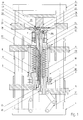
- Fig. 1 shows an axial schematic section through a punching device according to a first embodiment.
- the punching device stands on a base plate 1, on which guide columns 2 are attached.
- a punching device comprises usually four such guide columns 2, but with several punching devices can be performed by such a group of four guide columns 2 (see. below in connection with Figs. 3 and 4).
- the base plate 1 respectively arranged on the guide columns 2 are fixed on the one hand, the cover plate. 4 and a die holder 11 arranged below it.
- the cover plate 4 and the Die holder 11 may be fixedly connected to the guide columns 2 for fixing, But also on other fastening devices in relation to the Guide columns 2 to be fixed in place.
- the punching device described in the context of this embodiment is u.a. designed in a combined process initially from a Einlagematerialbahn 26 a liner 39 aus punch, and this deposit directly then apply to a container material web 27. To this direct transfer too ensure the container material web 27 above the die holder 11 and in a sense, on this resting led. Below the die holder is the Insert material web 26 out.
- the moving elements of the punching device are now below the die holder 11 arranged.
- the punching device is on the right half-side in the open state shown, and on the left half-side in the closed state immediately at Applying the insert to the sealing film 27, d. H. on the container material web.
- the movable elements of the punching devices comprise a lower holder 5, which via a toggle 24 on the guide columns 2 in the vertical direction is slidably mounted.
- Another movable element is the upper holder 6 to call, which also is slidably mounted on the guide columns 2 in the vertical direction.
- the upper Holder 6 can be moved relative to the lower holder 5 to a certain extent and this relative mobility is for a functioning of the stamping process crucial.
- the upper holder 6 is slidable via a guide rod 10 with the lower Holder 5 connected.
- the guide rod arranged parallel to the guide columns 2 10 is fixedly connected to the upper holder 6 and is at the lower holder 5 via a Guide holder 7, in which a sliding bearing 9 is arranged, slidably guided.
- a Adjusting nut 30 determined. This maximum distance is determined by at least one Cutting compression spring 23 forced. In other words, the upper level 6 only approximated against the spring force of the cutting compression spring 23 to the lower level 5 and this only up to another stop, then, namely, when the Guide rod 10 and the adjusting nut 30 with the surface of the lower Halters 5 comes into contact.
- an insulation 12 is first arranged on which then a bobbin 13 is placed.
- an electric coil 14 is arranged, which serves to a above the bobbin 13 arranged annular cutting edge 16 to heat inductively.
- a temperature sensor 29th is also arranged.
- the annular cutting edge 16 is connected via a clamping ring 15 on the bobbin 13 attached.
- the annular cutting edge 16 is essentially substantially cylindrical on the inside cut out circular ring formed, the cutting die 20 facing Outer surface, the cutting surface 44, tapered, d. H. it forms a cutting tip.
- the cutting surface 44 closes with the axis of the annular cutting edge 16 an angle of 30-45 °.
- the cutting tip of the annular cutting edge 16 is the Adjusted inside diameter of the cutting die 20 attached to the die holder 11.
- the cutting die 20 is made, just like the annular cutting edge 16 of a hardened Metal and is interchangeable and formed in the form of a circular ring.
- the Cutting dies 20 also has a cylindrical central opening whose Diameter but about 2/10 mm larger than the diameter of the cutting tip Ring cutting edge 16.
- the annular cutting edge 16 thus moves in a succession of the Ring cutting 16 on the cutting die 20 into the Schneidmatrize20 easy, and
- the material to be separated is on the one hand by the cutting tip and on the other clamped between the cutting surface 44 and the inner edge of the cutting die 20 respectively. separated.
- This the plunger 21st is on the lower side first in the guide holder 7 of the lower holder 5 in one Slide bearing guided.
- a sealing compression spring 22 clamped upward d. H. the plunger 21 can only against the Spring force of the sealing compression spring 22 against the lower holder 25 down be moved.
- the Seal 17 arranged, and this is firmly connected to the plunger 21.
- Sealing stamp 17 has in the area of the annular cutting edge 16 via a shoulder, which in a corresponding paragraph formed by the bobbin 13 and the Ring cutting 16 engages, so that the unit of seal stamp 17 and plunger 22 only can be inserted into the upper holder 6 until it reaches this paragraph.
- the Seal 17 set on the adjusting nut 25 such that the upper level of the Sealing stamp 17 substantially in a plane with the cutting tip of Ring cutting 16 comes to rest.
- a System provided with vacuum lines, which on the underside of the plunger 21st Vacuum is applied via a vacuum connection 28.
- the vacuum lines open at the upper-side inner surface of the seal stamp 17 in small holes, and serve the punched insert 39 in their transport up to the Keep container material web 27 on the seal 17 stamp.
- a sealing heater 18 is arranged Immediately above the cutting die 20 and between die holder 11 and Cover plate 4 is coaxial with the movable just described below arranged elements of the punch a sealing heater 18 is arranged. These Sealing heater 18 is attached via an insulation 19 on the cover plate 4.
- the Sealing heater 18 is formed substantially as a cylindrical punch, the is electrically maintained at a temperature which is a sealing of the inserts 39 allowed with the container material web 27. The sealed heater 18 is doing so above the container material web 27 arranged that between the container material web 27 and Seal heater 18 a distance of about 1/2 mm remains.
- the individual elements lower holder 5, upper holder 6 and plunger 21 with it fastened seal stamp 17 are in other words adjustable relative to each other displaceable and movable, and the mobility is described below on the basis of Description of the operation will be described in a punching operation.
- the punching device is in the open position on the right side State shown. In this open state, the annular cutting edge 16 of the Cutting die 20 spaced.
- the insert material web 26 is guided, namely Preferably, such that they neither the cutting die 20 nor the annular cutting edge 16 touched.
- Einlagematerialbahn in the present case, a train Polyurethane fleece made of Estane® with a basis weight of 50 grams per Square meters.
- a sealing film 27 respectively a Container material web led. It is a metal track resp. a tin from, for example, aluminum, which is already provided with a coating, which applying and simultaneously securing the inserts 39 on the Container material web 27 is allowed by simple local heating (typically if the coating is an acrylic based hot sealing varnish).
- the Coating must for this purpose at least on the seal heater 18th remote side on the container material web 27 may be present.
- the Container material web 27 is spaced from the seal heater 18, it should between seal heater and container material web at least a distance of 1/2 mm remain.
- Both the container material web 27 and the insert material web 26 have the reached desired position, via the toggle lever 24, the entire unit as it is shown in the right half-plane of Fig. 1, moved upward. After a corresponding displacement is first a contact between the annular cutting edge 16 (And optionally the surface of the seal stamp 17) with the insert material web 26 take place. Since the insert material web 26 is flexible, it becomes more in the other Displacement of seal punch 17 and cup 16 up and last against pressed the cutting die 20. At the moment in which the Einlagematerialbahn 26 between the annular cutting edge 16 and the cutting dies 20 is pressed, is a Separation of the insert material web to form the deposits 39 take place.
- this separation occurs due to the mechanical separation effect between Ring cutting 16 (respectively cutting surface 44) and cutting die 20 instead,
- a more extensive separation effect the heating of the annular cutting edge 16 is reached.
- the ring cutter 16 becomes at least at the moment of punching at a temperature in the range of 75-90 ° or held more thin, and accordingly thin fibers, which by the mechanical Effect can not be separated enough, separated by the action of heat.
- the Sealing heater 18, which at a temperature of about 160 ° or depending on Melting point of the sealing medium is held, now causes the deposit between Stamp 17 and container material web 27 respectively seal heater 18 pressed and is heated so that the arranged on the container material web 27 coating at least partially melts and a firm connection between deposit and Container material web 27 leads.
- the applied pressure is through the seal-pressure spring 22 determined.
- the toggle is stretched out in this position, and a further rotation then leads again to a movement apart of the punch.
- Container material web 27 and insert material web 26 can now move to the next one required position to be postponed.
- FIG. 2 Another embodiment of a punching device is shown in Fig. 2, wherein corresponding parts are the same as in Fig. 1. Accordingly, the following only the essential differences between Fig. 1 and 2 will be discussed.
- the die holder 11 and the cover plate 4 are not on the Guide columns 2 attached, but rather to other support columns 33rd Die Guide columns 2 are limited at their upper end via a closure plate 34, on which is typically the insert material web 26 is guided.
- the annular cutting edge 16 and the cutting die 20 in the case of Wear replaceable provided.
- FIG. 3 now shows a plan view of a device in which 8 inserts 39 simultaneously and synchronously by 8 punching devices as shown in Fig. 1 and Fig. 2nd are shown punched out.
- Fig. 3 is visible as the container material web 27 is transported in a first main feed direction 35, and the Einlagematerialbahn in a second main feed direction 36, which perpendicular to the first feed direction 35 is.
- two Einlagematerialbahnen 40 and 41 out parallel to each other and after a certain pattern (see Fig. 4) traveled.
- the procedure for sequential processing of individual punching positions in the insert material web 40 is referred to the method described in detail in CH 0739/03, and this This item is explicitly included in the disclosure.
- Fig. 3 Regarding the procedure for sequential processing of individual punching positions in the insert material web 40 is referred to the method described in detail in CH 0739/03, and this This item is explicitly included in the disclosure.
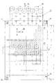
- FIG. 1 the container material web 27, which is completely filled with inserts 39, is shown, it becomes visible how the container material web, which has a width a of approximately 469 mm, is fitted with inserts 39 under maximum material utilization (the diameter 38 is 63.5 mm). This is achieved by the displacement pattern as indicated in the middle region by the sequence of the numbers within the illustrated liner web 43 while optimally utilizing the material of the liner web 43.
Landscapes
- Life Sciences & Earth Sciences (AREA)
- Forests & Forestry (AREA)
- Engineering & Computer Science (AREA)
- Mechanical Engineering (AREA)
- Physics & Mathematics (AREA)
- Optics & Photonics (AREA)
- Perforating, Stamping-Out Or Severing By Means Other Than Cutting (AREA)
- Electrical Discharge Machining, Electrochemical Machining, And Combined Machining (AREA)
- Processing And Handling Of Plastics And Other Materials For Molding In General (AREA)
- Containers And Plastic Fillers For Packaging (AREA)
- Filtering Materials (AREA)
Abstract
Description
Die vorliegende Erfindung betrifft ein Verfahren sowie eine Vorrichtung zum Ausstanzen von Einlagen aus einer Einlagematerialbahn aus einem nicht-gewobenen Material. Die Erfindung ist insbesondere im Bereich der Herstellung von Kaffeekapseln mit Einlagen aus Polyurethanvlies angesiedelt.The present invention relates to a method and a device for the Punching out inserts from a nonwoven insert sheet Material. The invention is particularly in the field of production of coffee capsules with inserts made of polyurethane fleece.
Vor allem in der Lebensmittelindustrie werden Behälter oft mit Einlagen versehen, die die verschiedenartigsten Funktionen erfüllen können. Beispielsweise können Behälter, in denen feuchtigkeitsempfindliches Pulver enthalten ist, mit einer Einlage versehen sein, die die Feuchtigkeit absorbiert und das Pulver trocken hält. Andere Behälter, in denen Flüssigkeiten enthalten sind, können mit selbstabdichtenden Einlagen versehen sein, so dass trotz einer Beschädigung des Behälters ein Auslaufen des Inhalts verhindert wird. Andere Anwendungen bestehen darin, Einlagen vorzusehen, welche nach Aktivierung eine Substanz in den Hauptraum freisetzen, wie dies z.B. bei Kapseln oder Becher für Trinkwasser der Fall sein könnte, in welche nach einem Anstechen o.ä. eine Desinfektionsflüssigkeit in kontrollierter Dosierung abgegeben wird.Especially in the food industry containers are often provided with deposits, the can fulfill the most diverse functions. For example, containers, in which moisture-sensitive powder is contained, provided with an insert which absorbs the moisture and keeps the powder dry. Other containers, in which contain liquids can be provided with self-sealing inserts be so that despite damage to the container leakage of the contents is prevented. Other applications are to provide inserts which release a substance into the main space upon activation, e.g. with capsules or cups for drinking water could be the case, in which after a piercing o.ä. a disinfectant is dispensed in controlled doses.
Selbstabdichtende Einlagen finden auch bei Kaffeepulver-Kapseln Anwendung. Dort sind die Einlagen üblicherweise am Boden der Kaffeepulver-Kapseln vorgesehen. Zur Kaffeezubereitung werden die Kapseln im Kaffeeautomaten mit einer Nadel oder mit 3 Stichmessem auf der Bodenfläche verteilt angestochen und Wasser wird durch das Kaffeepulver in die Kapseln eingeleitet. Nachdem der Kaffee zubereitet worden ist und die Nadel wieder herausgezogen wurde, bleiben die Kaffeepulver-Kapseln aufgrund der selbstabdichtenden Einlage dicht. Dadurch wird vermieden, dass beim Herausnehmen der Kaffeepulver-Kapseln Reste des heissen Zubereitungswassers auslaufen und den Benutzer verbrühen können und eine Verschmutzung der Kapselkammer des Kaffeeautomaten wird verhindert.Self-sealing inserts are also used for coffee powder capsules. There the deposits are usually provided on the bottom of the coffee powder capsules. to Coffee preparation, the capsules in the coffee machine with a needle or with 3 Stitch gauge is tapped on the floor area and water is thrown through the floor Coffee powder introduced into the capsules. After the coffee has been prepared and the needle has been pulled out again, the coffee powder capsules remain due to the self-sealing insert tight. This will avoid that when removing the coffee powder capsules leak remains of hot cooking water and the Users can scald and contaminate the capsule chamber of the Coffee machines are prevented.
Die Behälter werden aus einer Behältermaterialbahn, beispielsweise einem Aluminiumband, geformt. Sie werden aus einer Bahn ausgestanzt und anschliessend durch Umformen, wie beispielsweise Tiefziehen oder Blasformen, gefertigt. Die Einlagen selber werden aus einer bandförmigen Einlagenmaterialbahn herausgestanzt, bevor sie auf das Aluminiumband aufgesiegelt werden. Das Ausstanzen und Einbringen der Einlagen ist, speziell bei selbstabdichtenden Einlagen, oft mit technischen Schwierigkeiten verbunden: Selbstdichtende Einlagen weisen bei Zugbeanspruchung eine hohe Elastizität auf, damit sie beim Durchbohren der Behälterwand mitsamt der Einlage durch ihre Eigenelastizität das Loch sofort abdichten. Ausserdem weisen die Oberflächen solcher selbstdichtender Einlagen eine gewisse Adhäsionsfähigkeit auf, sodass die Lochränder bei einer Durchbohrung der selbstdichtenden Einlagen aneinander haften bleiben und die Abdichtung verstärken. Die hohe Elastizität des Einlagenmaterials hat einerseits zur Folge, dass eine Vorschubbewegung des Einlagenmaterialbandes nur mit geringer Geschwindigkeit erfolgen kann bzw. dass nur geringe Zugkräfte auf das Einlagenmaterial wirken können, andererseits führt sie zusammen mit anderen Materialeigenschaften dazu, dass der Stanzprozess typischerweise aufwändig durchgeführt werden muss, damit die Stanzung insbesondere bei hohen Produktionsgeschwindigkeiten stets sauber gewährleistet ist.The containers are made of a container material web, for example a Aluminum band, shaped. They are punched out of a train and then by forming, such as deep drawing or blow molding, manufactured. The Inserts themselves are punched out of a band-shaped Einlagenmaterialbahn, before they are sealed onto the aluminum strip. The punching and introduction Of the deposits is, especially with self-sealing deposits, often with technical Difficulties: Self-sealing inserts are subject to tensile stress a high elasticity, so they when drilling through the container wall together with the Insert by their own elasticity, the hole immediately seal. In addition, the Surfaces of such self-sealing inserts have a certain adhesiveness, so that the hole edges in a perforation of the self-sealing inserts stick together and reinforce the seal. The high elasticity of the Einlagenmaterials on the one hand with the result that a feed movement of the Einlagenmaterialbandes can only be done at low speed or that only low tensile forces can act on the deposit material, on the other hand it leads along with other material properties, that the stamping process typically must be carried out consuming, so that the punching in particular always guaranteed clean at high production speeds.
Das Herstellverfahren kann jedoch nur dann wirtschaftlich gestaltet werden, wenn die Behälter mit hohen Taktraten mit Einlagen versehen und hergestellt werden. However, the manufacturing process can only be made economical if the Containers with high clock rates with deposits and manufactured.
Der Erfindung liegt demnach die Aufgabe zugrunde, ein Verfahren, respektive eine Vorrichtung, zur Verfügung zu stellen, welches einen zuverlässigen und hohen Geschwindigkeiten zugänglichen Stanzprozess erlaubt, selbst beim Stanzen von Einlagen aus einer Einlagematerialbahn aus einem schwierig zu bearbeitenden nicht-gewobenen Material.The invention is therefore based on the object, a method, respectively a Device to provide a reliable and high Speeds-enabled punching process, even when punching Inserts made of an insert material web made of a difficult-to-machine nonwoven Material.
Die Lösung dieser Aufgabe wird dadurch erreicht, dass beim Verfahren in einem ersten Schritt die Einlagenmaterialbahn zwischen eine eine Stanzöffnung aufweisende Schneidmatrize und eine eine im Stanzbereich zur Stanzöffnung zulaufende Schneidfläche aufweisende entsprechende Schneide geführt wird, und in einem zweiten Schritt die Schneidmatrize und die Schneide in einer Richtung im wesentlichen senkrecht zur Ebene der Einlagenmaterialbahn derart aufeinander zugeführt werden, dass die Schneide in die Stanzöffnung der Schneidmatrize teilweise eingreift und die dazwischen liegende Einlagenmaterialbahn unter Ausbildung der Einlage ausgetrennt wird, wobei die Schneide und/oder die Schneidmatrize auf einer Temperatur gehalten werden, bei welcher eine wenigstens teilweise Abschmelzung des Einlagenmaterials stattfindet.The solution of this problem is achieved in that the method in a first Step the pad material web between a punched hole having Cutting die and one in the punching area to the punching opening tapered Cutting edge having corresponding cutting edge is performed, and in a second Step down the cutting die and the cutting edge in one direction substantially be fed to each other perpendicular to the plane of the Einlagenmaterialbahn, that the cutting edge partially engages in the punching opening of the cutting die and the intermediate liner material web separated to form the insert with the cutting edge and / or cutting die maintained at a temperature in which an at least partial melting of the deposit material takes place.
Der Kern der Erfindung besteht somit darin, den mechanischen Stanzprozess durch die Anwendung von erhöhter Temperatur zu unterstützen, und somit den klassischer Weise nur mechanisch durchgeführten Stanzprozess zu erleichtern respektive zu verbessern. Nach dem Stand der Technik werden derartige Einlagen typischerweise durch eine Kugelkopf-Schneide, welche sich zum Abtrennen bei eingeklemmtem Einlagematerial innerhalb der Schneidmatrize drehen muss, um überhaupt genügende Trennwirkung zu erzeugen, gestanzt. Ausserdem ist nach dem Stand der Technik eine grosse Stanzkraft erforderlich, um überhaupt eine genügende Wirkung zu erzeugen. Durch die zusätzliche Anwendung von Hitze kann entsprechend die Stanzkraft reduziert werden, da kleinste Fasern abgeschmolzen werden.The core of the invention thus consists in the mechanical punching process by the Application of increased temperature support, and thus the classic way to facilitate and improve only mechanically performed punching process. According to the prior art, such deposits are typically by a Ball-head cutting edge, which can be cut off when the insert material is clamped within the cutting die to ever sufficient separation effect produce, punched. In addition, according to the prior art, a large punching force required to produce a sufficient effect at all. By the additional Application of heat can be reduced according to the punching force, since smallest Fibers are melted off.
Ein derartiges Verfahren kann insbesondere dann angewendet werden, wenn es sich bei der Einlagematerialbahn um ein Polyurethanvlies, bevorzugt aus einem thermoplastischen Polyurethan auf Polyester- oder Polyetherbasis handelt, wobei dann insbesondere bevorzugt die Schneide und/oder die Schneidmatrize auf einer Temperatur im Bereich von 75°-90°C gehalten wird/werden. Z. B. im Bereich der Herstellung von Kaffeekapseln handelt es sich beim Polyurethanvlies um ein Polyurethanvlies mit einer Luftdurchlässigkeit von mehr als 300 l/m2/s und mit einer Porengrösse im Bereich von 10 bis 40 mm, bevorzugt bei einer Dicke von im Bereich von 0.1 bis 0.3 mm. Auch derartiges Material kann mit dem vorgeschlagenen Verfahren sehr effizient gestanzt werden.Such a method can be used in particular if the insert material web is a polyurethane nonwoven, preferably of a thermoplastic polyurethane based on polyester or polyether, in which case particularly preferably the cutting edge and / or the cutting die are at a temperature in the region of 75 ° -90 ° C is / are kept. For example in the field of production of coffee capsules, the polyurethane nonwoven is a polyurethane nonwoven with an air permeability of more than 300 l / m 2 / s and a pore size in the range of 10 to 40 mm, preferably at a thickness of in the range of 0.1 to 0.3 mm. Also, such material can be punched very efficiently with the proposed method.
Gemäss einer ersten bevorzugten Ausführungsform der Erfindung wird das Verfahren unter Verwendung einer Schneidmatrize durchgeführt, welche eine im wesentlichen zylindrische, bevorzugt kreiszylindrische Stanzöffnung aufweist, und wobei die Schneidfläche der Schneide mit der Zylinderachse einen spitzen Winkel, insbesondere bevorzugt im Bereich von 30 bis 60° (bevorzugt ca. 45°) einschliesst. Vorzugsweise ist dabei die Schneide derart ausgelegt, dass sie bei Kontakt der Schneidfläche mit der Schneidmatrize nur um wenige Zehntel Millimeter, beispielsweise nur 1/10mm in die Stanzöffnung der Schneidmatrize eingreift.According to a first preferred embodiment of the invention, the method performed using a cutting die, which is a substantially cylindrical, preferably circular cylindrical punch opening, and wherein the Cutting surface of the cutting edge with the cylinder axis at an acute angle, in particular preferably in the range of 30 to 60 ° (preferably about 45 °) includes. Preferably while the cutting edge designed so that they are in contact with the cutting surface with the Cutting die only by a few tenths of a millimeter, for example, only 1 / 10mm in the Punching opening of the cutting die engages.
Insbesondere aber nicht ausschliesslich im Bereich der Herstellung von Kaffeekapseln erweist es sich gemäss einer weiteren bevorzugten Ausführungsform der Erfindung als vorteilhaft, die Schneide als Ringschneide auszubilden, welche innerhalb der Schneidfläche über eine Öffnung verfügt, durch welche ein Stempel senkrecht zur Ebene der Einlagematerialbahn geführt wird, wobei in einem dritten Schritt des Verfahrens der Stempel die Einlage durch die Stanzöffnung abfiihrt, und wobei insbesondere bevorzugt diese Abführung auf eine zweite Materialbahn erfolgt. Die Einlage kann dabei bevorzugt durch die Stanzöffnung geführt werden und in Kontakt mit der zweiten Materialbahn gebracht werden, wobei insbesondere bevorzugt die Einlage mit der zweiten Materialbahn verbunden wird. Dies lässt sich beispielsweise aber nicht ausschliesslich im Bereich der Herstellung von Kaffeekapsel dadurch realisieren, dass die Einlage mit der zweiten Materialbahn in einem Heisssiegelprozess verbunden wird, wobei insbesondere bevorzugt auf der der Einlage abgewandten Seite der zweiten Materialbahn eine Siegelheizung angeordnet ist, welche auf einer Temperatur gehalten wird, welche eine Aktivierung eines auf der der Einlage zugewandten Seite der zweiten Materialbahn angeordneten Siegelmaterials auslöst.In particular, but not exclusively in the field of production of coffee capsules it turns out according to a further preferred embodiment of the invention as advantageous to form the cutting edge as a ring cutting, which within the Cutting surface has an opening through which a punch perpendicular to Level of the insert material web is guided, wherein in a third step of the Method of the punch discharges the insert through the punched opening, and wherein in particular, this removal preferably takes place on a second material web. The Insert can preferably be guided through the punch opening and in contact be brought with the second material web, with particular preference the Insert is connected to the second material web. This can be, for example but not exclusively in the field of coffee capsule production Realize that the insert with the second material web in a heat sealing process is connected, in particular preferably on the side facing away from the insert the second material web is arranged a sealing heater, which on a Temperature is maintained, which is an activation of one of the deposit facing side of the second material web arranged sealing material triggers.
Im Zusammenhang mit der Erwärmung von Schneide und/oder Schneidmatrize erweist es sich gemäss einer weiteren bevorzugten Ausführungsform als vorteilhaft, diese induktiv herbeizuführen. Es ist aber auch möglich, andere Erwärmungsverfahren zu verwenden wie beispielsweise elektrische Heizung, optische Heizung und Ähnliches. Die Aufheizung sollte dabei wenigstens im Moment der Zusammenführung von Schneide und/oder Schneidmatrize auf der gewünschten Temperatur gewährleistet sein, dies bevorzugt im Bereich von 50 bis 150° C, insbesondere bevorzugt im Bereich von 75 bis 100 °C. Bevorzugt wird die Schneide auf dieser Temperatur gehalten.In connection with the heating of cutting edge and / or cutting die proves It is advantageous according to a further preferred embodiment, this induce inductively. But it is also possible to use other heating methods use such as electric heating, optical heating and the like. The heating should at least at the moment of the merger of Cutting edge and / or cutting die to be ensured at the desired temperature, this preferably in the range of 50 to 150 ° C, particularly preferably in the range of 75 to 100 ° C. Preferably, the cutting edge is kept at this temperature.
Gemäss einer weiteren bevorzugten Ausführungsform handelt es sich beim Verfahren um ein Verfahren zum Herstellen von becherförmigen, mit einer Einlage versehenen Behältern (insbesondere von Kaffeekapseln), welches dadurch gekennzeichnet ist, dass die Einlagen vor dem Umformen der becherförmigen Behälter ausgestanzt werden, an den Stellen aufgebracht werden, an denen die Behälter in einem nachfolgenden Arbeitsgang durch Umformen gefertigt werden, und dass die becherförmigen Behälter anschliessend aus einer Behältermaterialbahn ausgestanzt und dann in einem Umformprozess geformt werden, wobei bevorzugt in einem Schritt zwischen 6 und 12 Einlagen, insbesondere bevorzugt 8 Einlagen ausgestanzt werden. Die Einlagen werden dabei bevorzugt aus einer Einlagenmaterialbahn ausgestanzt, und die Einlagenmaterialbahn und die Behältermaterialbahn werden derart übereinander zugeführt, dass die Einlagen unmittelbar nach deren Ausstanzen aus der Einlagenmaterialbahn auf die darunter resp. darüber liegende Behältermaterialbahn aufgebracht und mit dieser verbunden werden können. In diesem Zusammenhang erweist es sich als vorteilhaft, wenn Auftragsmuster abwechselnd aus wenigstens zwei Einlagenmaterialbändern ausgestanzt werden, wobei die zweite Einlagenmaterialbahn zum Ausstanzen in den Arbeitsbereich bewegt wird.According to a further preferred embodiment, the method is a method for producing cup-shaped, with a deposit Containers (in particular of coffee capsules), which is characterized in that the inserts are punched out before forming the cup-shaped container on be applied to the places where the container in a subsequent Operation are made by forming, and that the cup-shaped container then punched out of a container material web and then in a Shaping process are formed, wherein preferably in a step between 6 and 12 Inserts, particularly preferably 8 deposits are punched out. The deposits will be preferably punched out of a Einlagenmaterialbahn, and the Einlagenmaterialbahn and the container material web are so one above the other fed to the deposits immediately after their punching out of the Einlagenmaterialbahn on the underneath resp. overlying container material web applied and can be connected to this. In this context it proves to be advantageous if order patterns alternately from at least two Einlagenmaterialbändern be punched out, wherein the second Einlagenmaterialbahn for punching in the work area is moved.
Weitere bevorzugte Ausführungsformen des erfindungsgemässen Verfahrens sind in den abhängigen Ansprüchen beschrieben. Further preferred embodiments of the inventive method are in described the dependent claims.
Wie bereits erwähnt, betrifft die vorliegende Erfindung ausserdem eine Vorrichtung insbesondere zur Durchführung eines Verfahrens, wie es oben beschrieben wurde. Die Vorrichtung ist dabei zum Ausstanzen von Einlagen aus einer Einlagematerialbahn aus einem nicht-gewobenen Material vorgesehen, und umfasst eine Schneidmatrize mit einer Stanzöffnung sowie eine Schneide, zwischen welchen die Einlagematerialbahn getrennt wird. Die Vorrichtung ist insbesondere dadurch gekennzeichnet, dass die Schneide eine im Stanzbereich zur Stanzöffnung zulaufende Schneidfläche aufweist, dass die Schneidmatrize und die Schneide in einer Richtung im wesentlichen senkrecht zur Ebene der Einlagenmaterialbahn derart gelagert sind, dass sie aufeinander zugeführt werden können, wobei die Schneide in die Stanzöffnung der Schneidmatrize wenigstens teilweise eingreift und die dazwischen liegende Einlagenmaterialbahn unter Ausbildung der Einlage ausgetrennt wird, wobei Mittel angeordnet sind, mit Hilfe welcher die Schneide und/oder die Schneidmatrize auf einer Temperatur gehalten werden, bei welcher eine wenigstens teilweise Abschmelzung des Einlagenmaterials stattfindet.As already mentioned, the present invention also relates to a device in particular for carrying out a method as described above. The Device is for punching out deposits from a Einlagematerialbahn a non-woven material, and includes a cutting die with a punch opening and a cutting edge between which the insert material web is disconnected. The device is characterized in particular in that the Cutting edge has a cutting area tapering towards the punch opening in the punching area, that the cutting die and the cutting edge are substantially perpendicular in one direction are stored to the level of Einlagenmaterialbahn such that they are fed to each other can be, with the cutting edge in the punching opening of the cutting die at least partially engages and the intermediate Einlagenmaterialbahn under training the insert is separated, wherein means are arranged, by means of which the Cutting edge and / or the cutting die are kept at a temperature at which at least a partial melting of the deposit material takes place.
Vorzugsweise weist die Schneidmatrize eine im wesentlichen zylindrische, bevorzugt kreiszylindrische Stanzöffnung auf, und die Schneidfläche der Schneide (16) schliesst mit der zugehörigen Zylinderachse einen spitzen Winkel, insbesondere bevorzugt im Bereich von 30 bis 60°, bevorzugt im Bereich von 45 °, ein.Preferably, the cutting die has a substantially cylindrical, preferably circular cylindrical punch opening, and the cutting surface of the cutting edge (16) closes with the associated cylinder axis an acute angle, particularly preferably in Range of 30 to 60 °, preferably in the range of 45 °, a.
Um eine direkte Verschiebung resp. einen Transfer der Einlage auf ein zweites Medium zu ermöglichen, erweist es sich gemäss einer weiteren bevorzugten Ausführungsform als vorteilhaft, die Schneide als Ringschneide auszubilden, welche innerhalb der Schneidfläche über eine Öffnung verfügt, durch welche ein Stempel senkrecht zur Ebene der Einlagematerialbahn geführt werden kann. Dabei wird der Stempel dazu vorgesehen, die Einlage durch die Stanzöffnung im wesentlichen unmittelbar nach dem Stanzprozess abzuführen, wobei bevorzugt diese Abführung, vorzugsweise in einer linearen Bewegung (z. B. parallel zur relativen Bewegungsrichtung von Schneide und Schneidmatrize), auf eine zweite Materialbahn erfolgt, und wobei insbesondere bevorzugt weiterhin Mittel vorgesehen sind, mit Hilfe welcher die Einlage mit der zweiten Materialbahn verbunden werden kann. Bei den Mitteln kann es sich um eine Siegelheizung handeln, mit Hilfe welcher die Einlage mit der zweiten Materialbahn in einem Heisssiegelprozess verbunden werden kann. Dabei wird insbesondere bevorzugt die Siegelheizung auf der der Einlage abgewandten Seite der zweiten Materialbahn angeordnet, und die Siegelheizung wird auf einer Temperatur gehalten, welche eine Aktivierung eines auf der der Einlage zugewandten Seite der zweiten Materialbahn angeordneten Siegelmaterials (kann auf der Einlage oder auf der zweiten Materialbahn bereits vorgesehen sein) auslöst.To a direct shift resp. a transfer of the deposit to a second medium it proves to be possible according to a further preferred embodiment as advantageous to form the cutting edge as a cutting edge, which within the Cutting surface has an opening through which a punch perpendicular to Level of the insert material web can be performed. The stamp is added provided, the insert through the punch opening substantially immediately after the To dissipate punching process, preferably this discharge, preferably in one linear movement (eg, parallel to the relative direction of movement of the cutting edge and Schneidmatrize), takes place on a second material web, and wherein in particular Preferably further means are provided, by means of which the insert with the second material web can be connected. The funds may be a Seal heating act, with the help of which the insert with the second material web in a marriage sealing process can be connected. It is particularly preferred the sealing heater on the side facing away from the insert of the second material web arranged, and the seal heater is maintained at a temperature which a Activation of a side of the second material web facing the insert arranged sealing material (can on the insert or on the second material web already be provided) triggers.
Wie bereits erwähnt, kann die vorgeschlagene Vorrichtung insbesondere im Bereich der Herstellung von becherförmigen, mit einer Einlage versehenen Behältern wie Kaffeepulver-Kapseln verwendet werden. Dabei sind eine Einlagenmaterialbahn, eine die Einlagenmaterialbahn in einem Arbeitsbereich überlappende Behältermaterialbahn und eine im Arbeitsbereich angeordnete Stanzvorrichtung vorgesehen, durch welche die Einlagen an in einem vorbestimmten Auftragsmuster angeordneten Stanzpositionen ausstanzbar und in vorbestimmten Behälterpositionen auf der Behältermaterialbahn aufbringbar sind, wobei bevorzugt eine Vorschubeinrichtung vorhanden ist, durch welche die Stanzeinrichtung und die Einlagenmaterialbahn wenigstens bei einem Teil der Verschiebungsschritte im wesentlichen quer zur Bahnrichtung der Einlagenmaterialbahn relativ zueinander beweglich antreibbar sind. Im Zusammenhang mit diesem Verfahren wird explizit auf die schweizerische Anmeldung CH 0739/03 vom 25.04.2003 resp. die zugehörige europäische Patentanmeldung verwiesen, deren Inhalt an dieser Stelle ausdrücklich in den Offenbarungsgehalt der vorliegenden Schrift eingeschlossen werden soll.As already mentioned, the proposed device can be used in particular in the field of Production of cup-shaped containers provided with a liner such as Coffee powder capsules are used. Here are a Einlagenmaterialbahn, a the deposit material web in a work area overlapping container material web and a punching device arranged in the working area, through which the Inserts on stamping positions arranged in a predetermined application pattern punched out and in predetermined container positions on the container material web can be applied, wherein preferably a feed device is present by which the punching device and the Einlagenmaterialbahn at least at one part the displacement steps substantially transverse to the web direction of Einlagenmaterialbahn are movable relative to each other movable. In connection with this procedure is explicit on the Swiss application CH 0739/03 from 25.04.2003 resp. the associated European patent application, whose Content at this point expressly in the disclosure of the present document should be included.
Gemäss einer weiteren bevorzugten Ausführungsform der Vorrichtung gemäss der Erfindung verfügt der Siegelstempel über Mittel, insbesondere in Form von Mitteln zum Anlegen eines Unterdruckes (z.B. Vakuumleitungen mit Öffnungen auf der Stempeloberseite, wobei das Vakuum in Abhängigkeit des Stanzzyklus jeweils im wesentlichen nur angelegt ist, während der Transport auf eine zweite Materialbahn stattfindet), mittels welcher die Einlage zwischen dem Stanzen und dem Aufbringen auf die zweite Materialbahn am Siegelstempel gehalten werden kann.According to a further preferred embodiment of the device according to the Invention, the seal stamp on means, especially in the form of means for Applying a negative pressure (e.g., vacuum lines with openings on the Stamp top, wherein the vacuum depending on the punching cycle respectively in essential only applied while transporting to a second web takes place), by means of which the insert between the punching and the application on the second web can be held on the seal.
Insbesondere im Zusammenhang mit der Herstellung von Kaffeekapseln erweist es sich als vorteilhaft, die Schneidmatrize in einer ersten stationären Ebene anzuordnen (in einem Matrizenhalter), wobei oberhalb dieser ersten stationären Ebene die zweite Materialbahn (z. B. Behältermaterialbahn) und oberhalb dieser zweiten Materialbahn eine Siegelheizung (zum Befestigen der Einlagen auf der Behältermaterialbahn) angeordnet sind. Dabei ist unterhalb der ersten stationären Ebene eine bevorzugt als Ringschneide ausgebildete Schneide (zum teilweisen Eingriff in die Schneidmatrize ausgelegt) senkrecht zur ersten stationären Ebene verschieblich gelagert, und ein Siegelstempel ist innerhalb der Ringschneide zu dieser axial verschieblich gelagert. So kann, wenn die Einlagematerialbahn zwischen Schneide und Schneidmatrize zugeführt wird, zunächst zwischen Schneide und Schneidmatrize die Einlage gestanzt werden, und diese anschliessend ohne jegliche Zwischenlagerung, grosse Verschiebung oder Ähnliches direkt auf die oberhalb geführte zweite Materialbahn in einer linearen Bewegung von unten aufgebracht werden, und mit dieser unter Zuhilfenahme der Siegelheizung verbunden werden. Anschliessend kann beispielsweise eine derart mit den Einlagen versehene Materialbahn in einem Umformprozess (in Kombination mit einem weiteren Stanzprozess der zweiten Materialbahn) zu Kaffeekapseln weiterbearbeitet werden.In particular, in connection with the production of coffee capsules proves it as advantageous to arrange the cutting die in a first stationary plane (in a die holder), wherein above this first stationary plane, the second Material web (eg container material web) and above this second material web a sealed heater (for fixing the deposits on the container material web) are arranged. In this case, one below the first stationary level is preferred as Ring cutting edge formed cutting edge (for partial engagement in the cutting die designed) slidably mounted perpendicular to the first stationary plane, and a Sealing stamp is mounted axially displaceable within the annular cutting edge to this. So can, when the insert material web fed between the cutting edge and the cutting die is first punched between the cutting edge and cutting die insert, and These then without any intermediate storage, large shift or Similar directly to the above-guided second web in a linear Movement be applied from below, and with this with the help of the Seal heater to be connected. Subsequently, for example, such with the inserts provided web in a forming process (in combination with another punching process of the second material web) to coffee capsules be further processed.
Im Zusammenhang mit einer effizienten und parallelen Herstellung von einer Vielzahl von Einlagen respektive gegebenenfalls einer Vielzahl von Kaffeekapseln kann es sich als vorteilhaft erweisen, in einer ersten Ebene mehrere Schneidmatrizen anzuordnen, und in einer zweiten Ebene eine entsprechende Anzahl Schneiden anzuordnen, und die erste und die zweite Ebene während des Stanzprozesses zueinander synchronisiert zu bewegen.In the context of efficient and parallel production of a variety deposits or, where appropriate, a large number of coffee capsules may be prove advantageous to arrange a plurality of cutting dies in a first plane, and to arrange a corresponding number of blades in a second plane, and the first and second levels synchronized with each other during the punching process move.
Weitere bevorzugte Ausführungsformen der erfindungsgemässen Vorrichtung sind in den abhängigen Ansprüchen beschrieben.Further preferred embodiments of the inventive device are in described the dependent claims.
Die Erfindung soll nachfolgend anhand von Ausführungsbeispielen im Zusammenhang mit den Zeichnungen näher erläutert werden. Es zeigen:
- Fig. 1
- einen axialen Teilschnitt durch eine Stanzvorrichtung gemäss der Erfindung, wobei in der rechten Hälfte die Stanze im geöffneten Zustand dargestellt ist, und in der linken Hälfte die Stanze im geschlossenen Zustand dargestellt ist, wobei gleichzeitig die Einlage bereits auf einer zweiten Materialbahn fixiert wird;
- Fig. 2
- einen axialen Teilschnitt analog zu Fig. 1 eines weiteren Ausführungsbeispiels einer Stanze;
- Fig. 3
- eine schematische Aufsicht auf eine Stanze gemäss Fig. 1 oder Fig. 2, wobei mehrere derartige Stanzvorrichtungen parallel geschaltet sind; und
- Fig. 4
- eine schematische Aufsicht gemäss Fig. 3, wobei weiterhin das Stanz-respektive Auftragsmuster sowie die Bemassungen im Detail dargestellt sind.
- Fig. 1
- an axial partial section through a punching device according to the invention, wherein in the right half of the punch is shown in the open state, and in the left half of the punch is shown in the closed state, at the same time the insert is already fixed on a second material web;
- Fig. 2
- an axial partial section analogous to Figure 1 of another embodiment of a punch.
- Fig. 3
- a schematic plan view of a punch according to FIG. 1 or FIG. 2, wherein a plurality of such punching devices are connected in parallel; and
- Fig. 4
- a schematic plan view of FIG. 3, wherein further the punching respectively order pattern and the dimensions are shown in detail.
Fig. 1 zeigt einen axialen schematischen Schnitt durch eine Stanzvorrichtung gemäss
einem ersten Ausführungsbeispiel. Die Stanzvorrichtung steht auf einer Grundplatte 1,
auf welcher Führungssäulen 2 befestigt sind. Eine Stanzvorrichtung umfasst
normalerweise vier derartige Führungssäulen 2, wobei aber mehrere Stanzvorrichtungen
von einer derartigen Gruppe von vier Führungssäulen 2 geführt werden können (vgl.
weiter unten im Zusammenhang mit Fig. 3 und 4). In Bezug auf die Grundplatte 1
respektive auf die Führungssäulen 2 fix angeordnet sind einerseits die Deckplatte 4
sowie ein unterhalb davon angeordneter Matrizenhalter 11. Die Deckplatte 4 sowie der
Matrizenhalter 11 können zur Fixierung fest mit den Führungssäulen 2 verbunden sein,
können aber auch an anderen Befestigungsvorrichtungen in Bezug auf die
Führungssäulen 2 ortsfest befestigt sein.Fig. 1 shows an axial schematic section through a punching device according to
a first embodiment. The punching device stands on a
Die im Rahmen dieses Ausführungsbeispiels beschriebene Stanzvorrichtung ist u.a.
dafür ausgelegt, in einem kombinierten Verfahren zunächst aus einer
Einlagematerialbahn 26 eine Einlage 39 auszustanzen, und diese Einlage unmittelbar
danach auf eine Behältermaterialbahn 27 aufzubringen. Um diesen direkten Transfer zu
gewährleisten, wird die Behältermaterialbahn 27 oberhalb des Matrizenhalters 11 und
gewissermassen auf diesem aufliegend geführt. Unterhalb des Matrizenhalters wird die
Einlagematerialbahn 26 geführt.The punching device described in the context of this embodiment is u.a.
designed in a combined process initially from a
Einlagematerialbahn 26 a
Endgültig geht es dabei darum, Einlagen auf die Behältermaterialbahn und 20 aufzubringen und in einem anschliessenden, von der vorliegenden Stanzvorrichtung unabhängigen Prozess aus der Behältermaterialbahn Kaffeekapseln in einem Umformprozess herzustellen.Ultimately, it is about deposits on the container material web and 20 apply and in a subsequent, of the present punching device independent process from the container material coffee capsules in one Forming process to produce.
Die beweglichen Elemente der Stanzvorrichtung sind nun unterhalb des Matrizenhalters
11 angeordnet. Um die einzelnen Verfahrensschritte in einer einzigen Fig. darstellen zu
können, ist die Stanzvorrichtung auf der rechten Halbseite im geöffneten Zustand
dargestellt, und auf der linken Halbseite im geschlossenen Zustand unmittelbar beim
Aufbringen der Einlage auf die Siegelfolie 27, d. h. auf die Behältermaterialbahn. Die
beweglichen Elemente der Stanzvorrichtungen umfassen einen unteren Halter 5,
welcher über einen Kniehebel 24 an den Führungssäulen 2 in vertikaler Richtung
verschiebbar gelagert ist.The moving elements of the punching device are now below the
Als weiteres bewegliches Element ist der obere Halter 6 zu nennen, welcher ebenfalls
an den Führungssäulen 2 in vertikaler Richtung verschiebbar gelagert ist. Der obere
Halter 6 kann dabei bezüglich des unteren Halters 5 in einem gewissen Umfang bewegt
werden, und diese relative Beweglichkeit ist für ein Funktionieren des Stanzprozesses
entscheidend.Another movable element is the
Der obere Halter 6 ist über eine Führungsstange 10 verschieblich mit dem unteren
Halter 5 verbunden. Die parallel zu den Führungssäulen 2 angeordnete Führungsstange
10 ist fest mit dem oberen Halter 6 verbunden und wird am unteren Halter 5 über einen
Führungshalter 7, in welchem ein Gleitlager 9 angeordnet ist, verschiebbar geführt. Der
maximale Abstand von oberen Halter 6 und unteren Halter 5 wird dabei über eine
Einstellmutter 30 bestimmt. Dieser maximale Abstand wird durch wenigstens eine
Schneid-Druckfeder 23 erzwungen. Mit anderen Worten kann die obere Ebene 6 nur
gegen die Federkraft der Schneid-Druckfeder 23 an die untere Ebene 5 angenähert
werden, und dies auch nur bis zu einem weiteren Anschlag, dann nämlich, wenn die
Führungsstange 10 respektive die Einstellmutter 30 mit der Oberfläche des unteren
Halters 5 in Kontakt kommt. The
Auf der oberen Seite des oberen Halters 6 ist zunächst eine Isolation 12 angeordnet, auf
welcher anschliessend ein Spulenkörper 13 aufgesetzt ist. Innerhalb dieses
Spulenkörpers 13 ist eine elektrische Spule 14 angeordnet, welche dazu dient, eine
oberhalb des Spulenkörpers 13 angeordneten Ringschneide 16 induktiv aufzuheizen.
Zur Kontrolle der Temperatur der Ringschneide 16 ist zudem ein Temperaturfühler 29
angeordnet. Die Ringschneide 16 ist über einen Klemmring 15 auf dem Spulenkörper
13 befestigt.On the upper side of the
Die Ringschneide 16 ist im wesentlichen als innenseitig im wesentlichen zylindrisch
ausgeschnittener Kreisring ausgebildet, dessen der Schneidmatrize 20 zugewandte
Aussenfläche, die Schneidfläche 44, konisch zulaufend ausgebildet ist, d. h. es bildet
sich eine Schneidspitze. Die Schneidfläche 44 schliesst mit der Achse der Ringschneide
16 einen Winkel von 30-45° ein. Die Schneidspitze der Ringschneide 16 ist dem
Innendurchmesser der am Matrizenhalter 11 befestigten Schneidmatrize 20 angepasst.
Die Schneidmatrize 20 besteht, genau wie die Ringschneide 16 aus einem gehärteten
Metall und ist auswechselbar und in Form eines Kreisringes ausgebildet. Die
Schneidmatrizen 20 verfügt ebenfalls über eine zylindrische zentrale Öffnung, deren
Durchmesser aber zirka 2/10 mm grösser ist als der Durchmesser der Schneidspitze der
Ringschneide 16. Die Ringschneide 16 fährt also bei einem Aufeinanderzuführen der
Ringschneide 16 auf die Schneidmatrize 20 leicht in die Schneidmatrize20 hinein, und
das zu trennende Material wird einerseits durch die Schneidspitze und andererseits
zwischen der Schneidfläche 44 und der Innenkante der Schneidmatrize 20 geklemmt
resp. getrennt.The
Innerhalb der Ringschneide 16, d. h. in der zentralen Bohrung der Stanze, ist nun
ausserdem ein Siegelstempel 17 aus Kunststoff respektive ein Stössel 21 angeordnet,
welcher ebenfalls in vertikaler Richtung verschieblich gelagert ist. Dieser der Stössel 21
ist auf der unteren Seite zunächst im Führungshalter 7 des unteren Halters 5 in einem
Gleitlager geführt. Gegen den Anschlag einer Einstellmutter 25 ist der Stössel 21 über
eine Siegel-Druckfeder 22 nach oben verspannt, d. h. der Stössel 21 kann nur gegen die
Federkraft der Siegel-Druckfeder 22 gegen den unteren Halter 25 nach unten
verschoben werden. Im Bereich der Ringschneide 16 am Kopf des Stössels 21 ist der
Siegelstempel 17 angeordnet, und dieser ist fest mit dem Stössel 21 verbunden. Der
Siegelstempel 17 verfügt im Bereich der Ringschneide 16 über einen Absatz, welcher in
einen korrespondierenden Absatz gebildet durch den Spulenkörper 13 und die
Ringschneide 16 eingreift, so dass die Einheit aus Siegelstempel 17 und Stössel 22 nur
bis zum Erreichen dieses Absatzes in den oberen Halter 6 eingeschoben werden kann. In
der in der rechten Halbebene dargestellten offenen Stellung der Stanze wird der
Siegelstempel 17 über die Einstellmutter 25 derart eingestellt, dass die obere Ebene des
Siegelstempels 17 im wesentlichen in eine Ebene mit der Schneidspitze der
Ringschneide 16 zu liegen kommt.Within the
Innerhalb des Stössels 21 und insbesondere innerhalb des Siegelstempels 17 ist ein
System aus Vakuumleitungen vorgesehen, welche auf der Unterseite des Stössels 21
über einen Vakuumanschluss 28 mit Vakuum beaufschlagt wird. Die Vakuumleitungen
münden an der oberseitigen Innenfläche des Siegelstempel 17 in kleine Bohrungen, und
dienen dazu, die ausgestanzte Einlage 39 bei deren Transport nach oben an die
Behältermaterialbahn 27 am Siegelstempel 17 festzuhalten.Within the
Unmittelbar oberhalb der Schneidmatrize 20 und zwischen Matrizenhalter 11 und
Deckplatte 4 ist koaxial mit den beweglichen soeben beschriebenen unterhalb
angeordneten Elementen der Stanze eine Siegelheizung 18 angeordnet. Diese
Siegelheizung 18 ist über eine Isolation 19 an der Deckplatte 4 befestigt. Die
Siegelheizung 18 ist im wesentlichen als zylindrischer Stempel ausgebildet, der
elektrisch auf einer Temperatur gehalten wird, welche ein Versiegeln der Einlagen 39
mit der Behältermaterialbahn 27 erlaubt. Die Siegelheizung 18 wird dabei so oberhalb
der Behältermaterialbahn 27 angeordnet, dass zwischen Behältermaterialbahn 27 und
Siegelheizung 18 ein Abstand von zirka 1/2 mm verbleibt.Immediately above the cutting die 20 and between
Die einzelnen Elemente unterer Halter 5, oberer Halter 6 sowie Stössel 21 mit daran
befestigtem Siegelstempel 17 sind mit anderen Worten einstellbar relativ zueinander
verschiebbar und beweglich, und die Beweglichkeit soll im folgenden anhand der
Beschreibung der Funktionsweise bei einem Stanzvorgang beschrieben werden.The individual elements
Wie bereits erwähnt ist auf der rechten Seite die Stanzvorrichtung im geöffneten
Zustand dargestellt. In diesem geöffneten Zustand ist die Ringschneide 16 von der
Schneidmatrize 20 beabstandet.As already mentioned, the punching device is in the open position on the right side
State shown. In this open state, the
Zwischen diesen beiden Elementen ist die Einlagematerialbahn 26 geführt, und zwar
bevorzugtermassen so, dass sie weder die Schneidmatrize 20 noch die Ringschneide 16
berührt. Als Einlagematerialbahn wird im vorliegenden Fall eine Bahn aus
Polyurethanvlies aus Estane® mit einem Flächengewicht von 50 Gramm pro
Quadratmeter.Between these two elements, the
Oberhalb des Matrizenhalters 11 wird eine Siegelfolie 27 respektive eine
Behältermaterialbahn geführt. Es handelt sich dabei um eine Metallbahn resp. ein Blech
aus beispielsweise Aluminium, welches bereits mit einer Beschichtung versehen ist,
welche ein Aufbringen und gleichzeitiges Befestigen der Einlagen 39 auf der
Behältermaterialbahn 27 durch eine einfache lokale Erwärmung erlaubt (typischerweise
handelt es sich bei der Beschichtung um einen Heisssiegellack auf Acrylbasis). Die
Beschichtung muss zu diesem Zweck wenigstens auf der der Siegelheizung 18
abgewandten Seite auf der Behältermaterialbahn 27 vorhanden sein. Die
Behältermaterialbahn 27 wird beabstandet von der Siegelheizung 18 geführt, es sollte
zwischen Siegelheizung und Behältermaterialbahn wenigstens ein Abstand von 1/2 mm
verbleiben.Above the
Haben sowohl die Behältermaterialbahn 27 als auch die Einlagematerialbahn 26 die
gewünschte Position erreicht, wird über den Kniehebel 24 die gesamte Einheit wie sie
in der rechten Halbebene von Fig. 1 dargestellt ist, nach oben bewegt. Nach einer
entsprechenden Verschiebung wird zunächst ein Kontakt zwischen der Ringschneide 16
(und gegebenenfalls der Oberfläche des Siegelstempels 17) mit der Einlagematerialbahn
26 stattfinden. Da die Einlagematerialbahn 26 flexibel ist, wird sie bei der weiteren
Verschiebung von Siegelstempel 17 und Ringschneide 16 nach oben und zuletzt gegen
die Schneidmatrize 20 gedrückt. Im Moment, in welchem die Einlagematerialbahn 26
zwischen der Ringschneide 16 und der Schneidmatrizen 20 gepresst wird, wird eine
Trennung der Einlagematerialbahn unter Ausbildung der Einlagen 39 stattfinden.
Einerseits findet diese Trennung aufgrund der mechanischen Trennwirkung zwischen
Ringschneide 16 (respektive Schneidfläche 44) und Schneidmatrize 20 statt,
andererseits wird aber auch erfindungsgemäss eine weitergehende Trennwirkung durch
die Beheizung der Ringschneide 16 erreicht. Die Ringschneide 16 wird nämlich
wenigstens im Moment des Stanzens auf einer Temperatur im Bereich von 75-90° oder
mehr gehalten, und entsprechend werden dünne Fasern, welche durch die mechanische
Wirkung nicht genügend getrennt werden, durch die Wärmeeinwirkung getrennt.Both the
Nach Erreichen des Kontakts zwischen Ringschneide 16 und Schneidmatrize 20 ist der
obere Halter 16 bezüglich des Matrizenhalters 11 in seiner Position fixiert. Da nun der
Kniehebel 24 den unteren Halter 5 gegen die Kraft der Feder 23 weiter nach oben
presst, wird der Stössel 21, respektive der an dessen Spitze angeordnete Siegelstempel
17, auf welchem über das Vakuum 3 die nun ausgestossene Einlage 39 fixiert ist, durch
die zentrale Öffnung der Ringschneide 16 und durch die zentrale Öffnung der
Schneidmatrize 20 hindurch zur Behältermaterialbahn 27 verschoben. Die
Behältermaterialbahn 27 wird durch die Kraft des Stempels 17 an die Siegelheizung 18
gepresst, dieser Zustand ist nun auf der linken Seite von Fig. 1 dargestellt. Die
Siegelheizung 18, welche auf einer Temperatur von zirka 160° bzw. abhängig vom
Schmelzpunkt des Siegelmediums gehalten ist, bewirkt nun, dass die Einlage zwischen
Stempel 17 und Behältermaterialbahn 27 respektive Siegelheizung 18 gepresst und
erhitzt wird, so dass die auf der Behältermaterialbahn 27 angeordnete Beschichtung
wenigstens teilweise aufschmilzt und zu einer festen Verbindung zwischen Einlage und
Behältermaterialbahn 27 führt. Der dabei anliegende Druck wird durch die Siegel-Druckfeder
22 bestimmt. Der Kniehebel ist in dieser Position durchgestreckt, und eine
weitere Rotation führt anschliessend wieder zu einer Auseinanderbewegung der Stanze.
Behältermaterialbahn 27 und Einlagematerialbahn 26 können nun in die nächste
geforderte Position verschoben werden.After reaching the contact between
Ein weiteres Ausführungsbeispiel einer Stanzvorrichtung ist in Fig. 2 angegeben, wobei
entsprechende Teile gleich bezeichnet sind wie in Fig. 1. Entsprechend soll anfolgend
nur noch auf die wesentlichen Unterschiede zwischen Fig. 1 und 2 eingegangen werden.
In diesem Fall sind der Matrizenhalter 11 sowie die Deckplatte 4 nicht an den
Führungssäulen 2 befestigt, sondern vielmehr an weiteren Tragsäulen 33. Die
Führungssäulen 2 sind an ihrem oberen Ende über eine Abschlussplatte 34 begrenzt, auf
welcher typischerweise die Einlagematerialbahn 26 geführt ist. Wie bereits weiter oben
erwähnt, sind die Ringschneide 16 und die Schneidmatrize 20 für den Fall der
Abnutzung auswechselbar vorgesehen. Um einerseits die Auswechselbarkeit dieser
beiden Elemente zu vereinfachen, und um andererseits die Führung der
Einlagematerialbahn 26 justieren zu können, ist über eine erste Drehachse 31 die
Deckplatte 4 nach oben abkippbar und gleichermassen der Matrizenhalter 11 über eine
zweite Achse 32.Another embodiment of a punching device is shown in Fig. 2, wherein
corresponding parts are the same as in Fig. 1. Accordingly, the following
only the essential differences between Fig. 1 and 2 will be discussed.
In this case, the
Fig. 3 zeigt nun eine Aufsicht auf eine Vorrichtung, in welcher 8 Einlagen 39
gleichzeitig und synchron durch 8 Stanzvorrichtungen wie sie in Fig. 1 respektive Fig. 2
dargestellt sind, ausgestanzt werden. In Fig. 3 ist sichtbar, wie die Behältermaterialbahn
27 in einer ersten hauptsächlichen Vorschubrichtung 35 transportiert wird, und die
Einlagematerialbahn in einer zweiten hauptsächlichen Vorschubrichtung 36, welche
senkrecht zur ersten Vorschubrichtung 35 ist. Ausserdem werden zwei
Einlagematerialbahnen 40 und 41 parallel nebeneinander geführt und nach einem
bestimmten Muster (vgl. Fig. 4) abgefahren. In Bezug auf das Verfahren zur
sequenziellen Abarbeitung einzelner Stanzpositionen in der Einlagematerialbahn 40 sei
auf das in der CH 0739/03 im Detail beschriebene Verfahren verwiesen, und dieses an
dieser Stelle explizit in den Offenbarungsgehalt eingeschlossen. In Fig. 3 weiterhin
sichtbar ist der jeweilige Durchmesser 38, welcher anschliessend im nachgeschalteten
Umformprozess zu den eigentlichen Kaffeekapseln führt. Ist ein Abschnitt der ersten
Einlagematerialbahn 40 abgearbeitet, werden beide Bahnen des Einlagematerials in eine
zweite Position verschoben, so dass die zunächst untere und nicht bearbeitete
Einlagematerialbahn 41 für die nächste Stanzsequenz zur Verfügung steht, während die
erste Einlagematerialbahn 42 in der oberen Position in der Richtung 36 abtransportiert
werden kann.FIG. 3 now shows a plan view of a device in which 8 inserts 39
simultaneously and synchronously by 8 punching devices as shown in Fig. 1 and Fig. 2nd
are shown punched out. In Fig. 3 is visible as the
Die Einzelheiten dieses Verfahrens sind in Fig. 4 schematisch dargestellt. Oben ist die
vollständig mit Einlagen 39 bestückte Behältermaterialbahn 27 dargestellt, dabei wird
sichtbar, wie die Behältermaterialbahn, welche einer Breite a von zirka 469mm
aufweist, unter maximaler Materialausnützung (der Durchmesser 38 beträgt 63.5 mm)
mit Einlagen 39 bestückt ist. Dies wird durch das Verschiebungsmuster, wie es im
mittleren Bereich durch die Abfolge der Ziffern innerhalb der dargestellten
Einlagematerialbahn 43 angegeben ist, unter gleichzeitiger optimaler Ausnützung des
Materials der Einlagematerialbahn 43 erreicht. Dazu sind die Zentren der Einlagen 39 in
der Einlagematerialbahn 43 um g = 24.75 mm in der Vorschubrichtung 35 beabstandet,
und um d = 28.58 mm in der Vorschubrichtung 36. Die Achsen der einzelnen
Stanzvorrichtungen sind in Vorschubrichtung 35 um f = 99 mm beabstandet und in
Vorschubrichtung 36 um e = 114.32 mm, wobei die einzelnen Stanzpositionen
symmetrisch versetzt angeordnet sind. Die Einlagematerialbahnen verfügen dabei über
eine Breite b = 204 mm, und die für die beiden Bahnen 42 und 43 zur Verfügung
stehende Breite c beträgt 706.25 mm.
Das verwendete Verfahren erlaubt ein Durchführen von 85 Stanzungen pro Minute. The details of this method are shown schematically in FIG. At the top, the
The method used allows to perform 85 punches per minute.
- 11
- Grundplattebaseplate
- 22
- Führungssäuleguide column
- 33
- Vakuumleitungvacuum line
- 44
- Deckplattecover plate
- 55
- unterer Halterlower holder
- 66
- oberer Halterupper holder
- 77
- Führungshalterguide holder
- 88th
- Federführungleadership
- 99
- Gleitlagerbearings
- 1010
- Führungsstangeguide rod
- 1111
- Matrizenhalterdie holder
- 1212
- Isolation (Material)Isolation (material)
- 1313
- Spulenkörperbobbins
- 1414
- elektrische Spuleelectric coil
- 1515
- Klemmringclamping ring
- 1616
- Ringschneideserrated
- 1717
- Siegelstempelseal
- 1818
- Siegelheizungseal Heating
- 1919
- Heizungheater
- 2020
- Schneidmatrizecutting die
- 2121
- Stösseltappet
- 2222
- Siegel-Druckfeder Seal spring
- 2323
- Schneid-DruckfederCutting-pressure spring
- 2424
- Kniehebeltoggle
- 2525
- Einstellmutteradjusting
- 2626
- Filtervlies, EinlagematerialbahnFilter fleece, insert material web
- 2727
- Siegelfolie, BehältermaterialbahnSealing film, container material web
- 2828
- Vakuumsanschlussvacuum connection
- 2929
- Temperaturfühlertemperature sensor
- 3030
- Einstellmutteradjusting
- 3131
- Drehachse für 4Rotary axle for 4
- 3232
- Drehachse für 11Rotation axis for 11
- 3333
- Tragsäulesupport column
- 3434
- AbschlussplatteEnd plate
- 3535
- Vorschubrichtung von 27Feed direction of 27
- 3636
- Vorschubrichtung von 26Feed direction of 26
- 3737
- Durchmesser EinlageDiameter insert
- 3838
- Durchmesser Behältermaterial in BehältermaterialbahnDiameter of container material in container material web
- 3939
- Einlageinlay
- 4040
- erste Einlagematerialbahn (aktiv)first deposit material web (active)
- 4141
- zweite Einlagematerialbahn (passiv)second insert material web (passive)
- 4242
- erste Einlagematerialbahn (passiv)first deposit material web (passive)
- 4343
- zweite Einlagematerialbahn (aktiv)second insert material web (active)
- 4444
- Schneidfläche von 16Cutting area of 16
- 4545
- Stanzöffnung von 20Punch opening of 20
Claims (27)
dadurch gekennzeichnet, dass in einem ersten Schritt die Einlagenmaterialbahn (26) zwischen eine eine Stanzöffnung (45) aufweisende Schneidmatrize (20) und eine eine im Stanzbereich zur Stanzöffnung (45) zulaufende Schneidfläche (44) aufweisende entsprechende Schneide (16) geführt wird,
und in einem zweiten Schritt die Schneidmatrize (20) und die Schneide (16) in einer Richtung im wesentlichen senkrecht zur Ebene der Einlagenmaterialbahn (26) derart aufeinander zugeführt werden, dass die Schneide (16) in die Stanzöffnung (45) der Schneidmatrize (20) teilweise eingreift und die dazwischen liegende Einlagenmaterialbahn (26) unter Ausbildung der Einlage (39) ausgetrennt wird, wobei die Schneide (16) und/oder die Schneidmatrize (20) auf einer Temperatur gehalten werden, bei welcher eine wenigstens teilweise Abschmelzung des Einlagenmaterials stattfindet.Method of punching inserts (39) from an insert material web (26) of a non-woven material,
characterized in that, in a first step, the insert material web (26) is guided between a cutting die (20) having a punched opening (45) and a corresponding cutting edge (16) which tapers into the punching opening (45),
and in a second step, the cutting die (20) and the cutting edge (16) are fed towards each other in a direction substantially perpendicular to the plane of the insert material web (26) such that the cutting edge (16) penetrates into the punching opening (45) of the cutting die (20 ) and the intermediate insert material web (26) is separated to form the insert (39), wherein the cutting edge (16) and / or the cutting die (20) are maintained at a temperature at which at least partial melting of the insert material takes place ,
dadurch gekennzeichnet, dass die Schneide (16) eine im Stanzbereich zur Stanzöffnung (45) zulaufende Schneidfläche (44) aufweist,
dass die Schneidmatrize (20) und die Schneide (16) in einer Richtung im wesentlichen senkrecht zur Ebene der Einlagenmaterialbahn (26) derart gelagert sind, dass sie aufeinander zugeführt werden können, wobei die Schneide (16) in die Stanzöffnung (45) der Schneidmatrize (20) wenigstens teilweise eingreift und die dazwischen liegende Einlagenmaterialbahn (26) unter Ausbildung der Einlage (39) ausgetrennt wird, wobei Mittel (13, 14) angeordnet sind, mit Hilfe welcher die Schneide (16) und/oder die Schneidmatrize (20) auf einer Temperatur gehalten werden, bei welcher eine wenigstens teilweise Abschmelzung des Einlagenmaterials stattfindet.Apparatus for punching inserts (39) from an insert material web (26) of a non-woven material comprising a cutting die (20) with a punched opening (45) and a cutting edge (16) between which the insert material web (26) is separated,
characterized in that the cutting edge (16) has a cutting surface (44) which tapers in the punching region to the punched opening (45),
in that the cutting die (20) and the cutting edge (16) are mounted in a direction substantially perpendicular to the plane of the insert material web (26) so that they can be fed to each other, wherein the cutting edge (16) into the punching opening (45) of the cutting die (20) at least partially engages and the intermediate Einlagenmaterialbahn (26) is separated to form the insert (39), wherein means (13, 14) are arranged, by means of which the cutting edge (16) and / or the cutting die (20). be maintained at a temperature at which takes place at least a partial melting of the deposit material.
Priority Applications (3)
| Application Number | Priority Date | Filing Date | Title |
|---|---|---|---|
| EP08100430A EP1914048A3 (en) | 2004-02-27 | 2005-02-25 | Method and device for punching a filter material |
| PL05405211T PL1568451T3 (en) | 2004-02-27 | 2005-02-25 | Method and apparatus for punching a filtering medium |
| SI200530150T SI1568451T1 (en) | 2004-02-27 | 2005-02-25 | Method and apparatus for punching a filtering medium |
Applications Claiming Priority (2)
| Application Number | Priority Date | Filing Date | Title |
|---|---|---|---|
| CH333042004 | 2004-02-27 | ||
| CH3332004 | 2004-02-27 |
Related Child Applications (1)
| Application Number | Title | Priority Date | Filing Date |
|---|---|---|---|
| EP08100430A Division EP1914048A3 (en) | 2004-02-27 | 2005-02-25 | Method and device for punching a filter material |
Publications (2)
| Publication Number | Publication Date |
|---|---|
| EP1568451A1 true EP1568451A1 (en) | 2005-08-31 |
| EP1568451B1 EP1568451B1 (en) | 2008-01-16 |
Family
ID=34744474
Family Applications (2)
| Application Number | Title | Priority Date | Filing Date |
|---|---|---|---|
| EP05405211A Active EP1568451B1 (en) | 2004-02-27 | 2005-02-25 | Method and apparatus for punching a filtering medium |
| EP08100430A Withdrawn EP1914048A3 (en) | 2004-02-27 | 2005-02-25 | Method and device for punching a filter material |
Family Applications After (1)
| Application Number | Title | Priority Date | Filing Date |
|---|---|---|---|
| EP08100430A Withdrawn EP1914048A3 (en) | 2004-02-27 | 2005-02-25 | Method and device for punching a filter material |
Country Status (7)
| Country | Link |
|---|---|
| EP (2) | EP1568451B1 (en) |
| AT (1) | ATE383930T1 (en) |
| DE (1) | DE502005002533D1 (en) |
| DK (1) | DK1568451T3 (en) |
| ES (1) | ES2298984T3 (en) |
| PL (1) | PL1568451T3 (en) |
| PT (1) | PT1568451E (en) |
Cited By (2)
| Publication number | Priority date | Publication date | Assignee | Title |
|---|---|---|---|---|
| US20210086986A1 (en) | 2010-07-22 | 2021-03-25 | K-Fee System Gmbh | Portion capsule having an identifier |
| CN112677507A (en) * | 2020-12-09 | 2021-04-20 | 南京精孔科技有限公司 | EPE foamed pearl wool lining packaging material and manufacturing and processing method thereof |
Citations (6)
| Publication number | Priority date | Publication date | Assignee | Title |
|---|---|---|---|---|
| US3623209A (en) * | 1968-08-14 | 1971-11-30 | Zuehlke & Braendli Ag | Method for separating blanks from plastic sheets |
| US4823660A (en) * | 1986-02-20 | 1989-04-25 | Stelron Components Inc | Label cutting device and method |
| US20020015768A1 (en) * | 1999-03-18 | 2002-02-07 | Petr Masek | Sealed cartridge for making a beverage |
| DE10032458A1 (en) * | 2000-07-04 | 2002-07-25 | Rehau Ag & Co | Punching tool for producing openings in workpieces made of thermoplastic material |
| DE10208997A1 (en) * | 2002-02-28 | 2003-09-11 | Bosch Gmbh Robert | Stamping method for sealed deep drawn thermoplastic cup like containers, comprises urging punches with different contours against cover and base films |
| EP1471012A2 (en) * | 2003-04-25 | 2004-10-27 | Ideacorp AG | Method and apparatus for manufacturing cup-shaped containers from material webs |
-
2005
- 2005-02-25 EP EP05405211A patent/EP1568451B1/en active Active
- 2005-02-25 DE DE502005002533T patent/DE502005002533D1/en active Active
- 2005-02-25 EP EP08100430A patent/EP1914048A3/en not_active Withdrawn
- 2005-02-25 PT PT05405211T patent/PT1568451E/en unknown
- 2005-02-25 PL PL05405211T patent/PL1568451T3/en unknown
- 2005-02-25 AT AT05405211T patent/ATE383930T1/en active
- 2005-02-25 ES ES05405211T patent/ES2298984T3/en active Active
- 2005-02-25 DK DK05405211T patent/DK1568451T3/en active
Patent Citations (6)
| Publication number | Priority date | Publication date | Assignee | Title |
|---|---|---|---|---|
| US3623209A (en) * | 1968-08-14 | 1971-11-30 | Zuehlke & Braendli Ag | Method for separating blanks from plastic sheets |
| US4823660A (en) * | 1986-02-20 | 1989-04-25 | Stelron Components Inc | Label cutting device and method |
| US20020015768A1 (en) * | 1999-03-18 | 2002-02-07 | Petr Masek | Sealed cartridge for making a beverage |
| DE10032458A1 (en) * | 2000-07-04 | 2002-07-25 | Rehau Ag & Co | Punching tool for producing openings in workpieces made of thermoplastic material |
| DE10208997A1 (en) * | 2002-02-28 | 2003-09-11 | Bosch Gmbh Robert | Stamping method for sealed deep drawn thermoplastic cup like containers, comprises urging punches with different contours against cover and base films |
| EP1471012A2 (en) * | 2003-04-25 | 2004-10-27 | Ideacorp AG | Method and apparatus for manufacturing cup-shaped containers from material webs |
Cited By (6)
| Publication number | Priority date | Publication date | Assignee | Title |
|---|---|---|---|---|
| US20210086986A1 (en) | 2010-07-22 | 2021-03-25 | K-Fee System Gmbh | Portion capsule having an identifier |
| US11554910B2 (en) | 2010-07-22 | 2023-01-17 | K-Fee System Gmbh | Portion capsule having an identifier |
| US11667465B2 (en) | 2010-07-22 | 2023-06-06 | K-Fee System Gmbh | Portion capsule having an identifier |
| US11820586B2 (en) | 2010-07-22 | 2023-11-21 | K-Fee System Gmbh | Portion capsule having an identifier |
| US11919703B2 (en) | 2010-07-22 | 2024-03-05 | K-Fee System Gmbh | Portion capsule having an identifier |
| CN112677507A (en) * | 2020-12-09 | 2021-04-20 | 南京精孔科技有限公司 | EPE foamed pearl wool lining packaging material and manufacturing and processing method thereof |
Also Published As
| Publication number | Publication date |
|---|---|
| ATE383930T1 (en) | 2008-02-15 |
| EP1914048A3 (en) | 2008-12-10 |
| EP1568451B1 (en) | 2008-01-16 |
| DE502005002533D1 (en) | 2008-03-06 |
| PL1568451T3 (en) | 2008-06-30 |
| ES2298984T3 (en) | 2008-05-16 |
| EP1914048A2 (en) | 2008-04-23 |
| DK1568451T3 (en) | 2008-03-25 |
| EP1914048A8 (en) | 2010-06-02 |
| PT1568451E (en) | 2008-02-12 |
Similar Documents
| Publication | Publication Date | Title |
|---|---|---|
| EP3140200B1 (en) | Method and device for producing molded parts from a continuous fiber-material sheet | |
| DE102009040802B4 (en) | Method and device for applying a sealant to a surface | |
| CH638716A5 (en) | METHOD FOR PRODUCING A MOLDED BODY FROM PLASTIC. | |
| DE1561966A1 (en) | Method and device for packaging goods | |
| EP2969478B1 (en) | Tubular bag, method and device for producing tubular bags | |
| DE1586266B2 (en) | DEVICE FOR FILLING AND SEALING CAPSULES AND THE LIKE | |
| WO2018054695A1 (en) | Device for connecting two container parts | |
| DE1142574B (en) | Device for manufacturing packaging containers | |
| DE2842515C2 (en) | Method for producing head pieces with a membrane for packaging containers made of laminate with a metallic barrier layer and device for carrying out the method | |
| DE1479334A1 (en) | Method and device for forming protrusions on thin sheet material | |
| EP1568451B1 (en) | Method and apparatus for punching a filtering medium | |
| EP1471012A2 (en) | Method and apparatus for manufacturing cup-shaped containers from material webs | |
| EP2289660B1 (en) | Device and process of cutting TDS and ODF materials with two pairs of advancing rolls | |
| DE19750075C2 (en) | Process for separating cover sheet films from a plastic film web and device for carrying out the process | |
| EP0482435A2 (en) | Method and device for determining the position of an element for marking a separation of flat articles in a pile | |
| DE19828004B4 (en) | Method for achieving a constant pressing force in tableting machines | |
| DE102011108954A1 (en) | Punching station for use in in-line narrow web-label printing machine for punching self-adhesive labels, has counter punching cylinder provided with hydrostatic bearing, which is provided with pair of hydrostatic slide bearings | |
| DE19610707C2 (en) | Method and device for producing a multi-layer packaging tray | |
| DE4418063C2 (en) | Machine for producing deep-drawn cups with feet | |
| EP2955011B1 (en) | Method and device for manufacturing a container | |
| EP3967637B1 (en) | Device and method for splicing and continuously providing a film sheet | |
| DE1217024B (en) | Filling and closing machine for two-part capsules | |
| DE2235281A1 (en) | METHOD AND APPARATUS FOR CONNECTING THE REAR END OF A TRAILING WEB OF MATERIALS TO THE FRONT END OF A NEW TRAIL FOR MACHINERY OF SUCH TRAILS | |
| DE1906796A1 (en) | Device for connecting inserts with sleeves using press jaws | |
| DE488090C (en) | Equipment for the production of coasters from cellulose wadding |
Legal Events
| Date | Code | Title | Description |
|---|---|---|---|
| PUAI | Public reference made under article 153(3) epc to a published international application that has entered the european phase |
Free format text: ORIGINAL CODE: 0009012 |
|
| AK | Designated contracting states |
Kind code of ref document: A1 Designated state(s): AT BE BG CH CY CZ DE DK EE ES FI FR GB GR HU IE IS IT LI LT LU MC NL PL PT RO SE SI SK TR |
|
| AX | Request for extension of the european patent |
Extension state: AL BA HR LV MK YU |
|
| 17P | Request for examination filed |
Effective date: 20060201 |
|
| AKX | Designation fees paid |
Designated state(s): AT BE BG CH CY CZ DE DK EE ES FI FR GB GR HU IE IS IT LI LT LU MC NL PL PT RO SE SI SK TR |
|
| AXX | Extension fees paid |
Extension state: HR Payment date: 20060201 |
|
| 17Q | First examination report despatched |
Effective date: 20060712 |
|
| RAP1 | Party data changed (applicant data changed or rights of an application transferred) |
Owner name: NESTEC S.A. |
|
| GRAP | Despatch of communication of intention to grant a patent |
Free format text: ORIGINAL CODE: EPIDOSNIGR1 |
|
| GRAS | Grant fee paid |
Free format text: ORIGINAL CODE: EPIDOSNIGR3 |
|
| GRAA | (expected) grant |
Free format text: ORIGINAL CODE: 0009210 |
|
| AK | Designated contracting states |
Kind code of ref document: B1 Designated state(s): AT BE BG CH CY CZ DE DK EE ES FI FR GB GR HU IE IS IT LI LT LU MC NL PL PT RO SE SI SK TR |
|
| AX | Request for extension of the european patent |
Extension state: HR |
|
| REG | Reference to a national code |
Ref country code: GB Ref legal event code: FG4D Free format text: NOT ENGLISH |
|
| REG | Reference to a national code |
Ref country code: PT Ref legal event code: SC4A Free format text: AVAILABILITY OF NATIONAL TRANSLATION Effective date: 20080131 |
|
| REG | Reference to a national code |
Ref country code: CH Ref legal event code: EP |
|
| REG | Reference to a national code |
Ref country code: IE Ref legal event code: FG4D Free format text: LANGUAGE OF EP DOCUMENT: GERMAN |
|
| REF | Corresponds to: |
Ref document number: 502005002533 Country of ref document: DE Date of ref document: 20080306 Kind code of ref document: P |
|
| REG | Reference to a national code |
Ref country code: GR Ref legal event code: EP Ref document number: 20080400572 Country of ref document: GR |
|
| REG | Reference to a national code |
Ref country code: DK Ref legal event code: T3 |
|
| GBT | Gb: translation of ep patent filed (gb section 77(6)(a)/1977) |
Effective date: 20080305 |
|
| REG | Reference to a national code |
Ref country code: RO Ref legal event code: EPE |
|
| REG | Reference to a national code |
Ref country code: SE Ref legal event code: TRGR |
|
| REG | Reference to a national code |
Ref country code: ES Ref legal event code: FG2A Ref document number: 2298984 Country of ref document: ES Kind code of ref document: T3 |
|
| REG | Reference to a national code |
Ref country code: HU Ref legal event code: AG4A Ref document number: E002901 Country of ref document: HU Ref country code: PL Ref legal event code: T3 |
|
| ET | Fr: translation filed | ||
| PG25 | Lapsed in a contracting state [announced via postgrant information from national office to epo] |
Ref country code: MC Free format text: LAPSE BECAUSE OF NON-PAYMENT OF DUE FEES Effective date: 20080228 |
|
| PLBE | No opposition filed within time limit |
Free format text: ORIGINAL CODE: 0009261 |
|
| STAA | Information on the status of an ep patent application or granted ep patent |
Free format text: STATUS: NO OPPOSITION FILED WITHIN TIME LIMIT |
|
| REG | Reference to a national code |
Ref country code: DK Ref legal event code: EBP |
|
| REG | Reference to a national code |
Ref country code: EE Ref legal event code: HC1A Ref document number: E001785 Country of ref document: EE |
|
| 26N | No opposition filed |
Effective date: 20081017 |
|
| PG25 | Lapsed in a contracting state [announced via postgrant information from national office to epo] |
Ref country code: CY Free format text: LAPSE BECAUSE OF FAILURE TO SUBMIT A TRANSLATION OF THE DESCRIPTION OR TO PAY THE FEE WITHIN THE PRESCRIBED TIME-LIMIT Effective date: 20080116 |
|
| PG25 | Lapsed in a contracting state [announced via postgrant information from national office to epo] |
Ref country code: LU Free format text: LAPSE BECAUSE OF NON-PAYMENT OF DUE FEES Effective date: 20080225 |
|
| PGFP | Annual fee paid to national office [announced via postgrant information from national office to epo] |
Ref country code: IT Payment date: 20120218 Year of fee payment: 8 |
|
| PGFP | Annual fee paid to national office [announced via postgrant information from national office to epo] |
Ref country code: HU Payment date: 20130212 Year of fee payment: 9 Ref country code: FI Payment date: 20130212 Year of fee payment: 9 Ref country code: SE Payment date: 20130212 Year of fee payment: 9 Ref country code: DE Payment date: 20130220 Year of fee payment: 9 Ref country code: FR Payment date: 20130301 Year of fee payment: 9 Ref country code: IE Payment date: 20130212 Year of fee payment: 9 Ref country code: CH Payment date: 20130212 Year of fee payment: 9 Ref country code: GB Payment date: 20130220 Year of fee payment: 9 Ref country code: DK Payment date: 20130212 Year of fee payment: 9 |
|
| PGFP | Annual fee paid to national office [announced via postgrant information from national office to epo] |
Ref country code: BE Payment date: 20130212 Year of fee payment: 9 Ref country code: NL Payment date: 20130209 Year of fee payment: 9 |
|
| PGFP | Annual fee paid to national office [announced via postgrant information from national office to epo] |
Ref country code: BG Payment date: 20131216 Year of fee payment: 10 |
|
| PGFP | Annual fee paid to national office [announced via postgrant information from national office to epo] |
Ref country code: PL Payment date: 20131216 Year of fee payment: 10 |
|
| PGFP | Annual fee paid to national office [announced via postgrant information from national office to epo] |
Ref country code: SK Payment date: 20140207 Year of fee payment: 10 Ref country code: IS Payment date: 20140109 Year of fee payment: 10 Ref country code: EE Payment date: 20140115 Year of fee payment: 10 Ref country code: LT Payment date: 20140124 Year of fee payment: 10 Ref country code: RO Payment date: 20140113 Year of fee payment: 10 Ref country code: CZ Payment date: 20140206 Year of fee payment: 10 |
|
| PGFP | Annual fee paid to national office [announced via postgrant information from national office to epo] |
Ref country code: GR Payment date: 20140120 Year of fee payment: 10 Ref country code: AT Payment date: 20140128 Year of fee payment: 10 Ref country code: SI Payment date: 20140114 Year of fee payment: 10 Ref country code: TR Payment date: 20140123 Year of fee payment: 10 Ref country code: ES Payment date: 20140113 Year of fee payment: 10 |
|
| PGFP | Annual fee paid to national office [announced via postgrant information from national office to epo] |
Ref country code: PT Payment date: 20140221 Year of fee payment: 10 |
|
| BERE | Be: lapsed |
Owner name: NESTEC S.A. Effective date: 20140228 |
|
| REG | Reference to a national code |
Ref country code: DE Ref legal event code: R119 Ref document number: 502005002533 Country of ref document: DE |
|
| REG | Reference to a national code |
Ref country code: NL Ref legal event code: V1 Effective date: 20140901 |
|
| REG | Reference to a national code |
Ref country code: DK Ref legal event code: EBP Effective date: 20140228 Ref country code: DK Ref legal event code: EBP Effective date: 20080430 |
|
| REG | Reference to a national code |
Ref country code: SE Ref legal event code: EUG Ref country code: CH Ref legal event code: PL |
|
| GBPC | Gb: european patent ceased through non-payment of renewal fee |
Effective date: 20140225 |
|
| PG25 | Lapsed in a contracting state [announced via postgrant information from national office to epo] |
Ref country code: FI Free format text: LAPSE BECAUSE OF NON-PAYMENT OF DUE FEES Effective date: 20140225 Ref country code: CH Free format text: LAPSE BECAUSE OF NON-PAYMENT OF DUE FEES Effective date: 20140228 Ref country code: NL Free format text: LAPSE BECAUSE OF NON-PAYMENT OF DUE FEES Effective date: 20140901 Ref country code: LI Free format text: LAPSE BECAUSE OF NON-PAYMENT OF DUE FEES Effective date: 20140228 |
|
| REG | Reference to a national code |
Ref country code: FR Ref legal event code: ST Effective date: 20141031 |
|
| REG | Reference to a national code |
Ref country code: DE Ref legal event code: R119 Ref document number: 502005002533 Country of ref document: DE Effective date: 20140902 |
|
| PG25 | Lapsed in a contracting state [announced via postgrant information from national office to epo] |
Ref country code: SE Free format text: LAPSE BECAUSE OF NON-PAYMENT OF DUE FEES Effective date: 20140226 Ref country code: HU Free format text: LAPSE BECAUSE OF NON-PAYMENT OF DUE FEES Effective date: 20140226 |
|
| REG | Reference to a national code |
Ref country code: IE Ref legal event code: MM4A |
|
| PG25 | Lapsed in a contracting state [announced via postgrant information from national office to epo] |
Ref country code: BE Free format text: LAPSE BECAUSE OF NON-PAYMENT OF DUE FEES Effective date: 20140228 Ref country code: DK Free format text: LAPSE BECAUSE OF NON-PAYMENT OF DUE FEES Effective date: 20140228 Ref country code: IE Free format text: LAPSE BECAUSE OF NON-PAYMENT OF DUE FEES Effective date: 20140225 Ref country code: GB Free format text: LAPSE BECAUSE OF NON-PAYMENT OF DUE FEES Effective date: 20140225 Ref country code: FR Free format text: LAPSE BECAUSE OF NON-PAYMENT OF DUE FEES Effective date: 20140228 Ref country code: DE Free format text: LAPSE BECAUSE OF NON-PAYMENT OF DUE FEES Effective date: 20140902 |
|
| REG | Reference to a national code |
Ref country code: PT Ref legal event code: MM4A Free format text: LAPSE DUE TO NON-PAYMENT OF FEES Effective date: 20150825 |
|
| REG | Reference to a national code |
Ref country code: AT Ref legal event code: MM01 Ref document number: 383930 Country of ref document: AT Kind code of ref document: T Effective date: 20150225 Ref country code: EE Ref legal event code: MM4A Ref document number: E001785 Country of ref document: EE Effective date: 20150228 |
|
| REG | Reference to a national code |
Ref country code: LT Ref legal event code: MM4D Effective date: 20150225 |
|
| PG25 | Lapsed in a contracting state [announced via postgrant information from national office to epo] |
Ref country code: BG Free format text: LAPSE BECAUSE OF NON-PAYMENT OF DUE FEES Effective date: 20150930 Ref country code: PT Free format text: LAPSE BECAUSE OF NON-PAYMENT OF DUE FEES Effective date: 20150825 Ref country code: CZ Free format text: LAPSE BECAUSE OF NON-PAYMENT OF DUE FEES Effective date: 20150225 Ref country code: SK Free format text: LAPSE BECAUSE OF NON-PAYMENT OF DUE FEES Effective date: 20150225 Ref country code: LT Free format text: LAPSE BECAUSE OF NON-PAYMENT OF DUE FEES Effective date: 20150225 Ref country code: RO Free format text: LAPSE BECAUSE OF NON-PAYMENT OF DUE FEES Effective date: 20150225 Ref country code: EE Free format text: LAPSE BECAUSE OF NON-PAYMENT OF DUE FEES Effective date: 20150228 |
|
| REG | Reference to a national code |
Ref country code: SK Ref legal event code: MM4A Ref document number: E 3331 Country of ref document: SK Effective date: 20150225 |
|
| REG | Reference to a national code |
Ref country code: GR Ref legal event code: ML Ref document number: 20080400572 Country of ref document: GR Effective date: 20150902 |
|
| PG25 | Lapsed in a contracting state [announced via postgrant information from national office to epo] |
Ref country code: SI Free format text: LAPSE BECAUSE OF NON-PAYMENT OF DUE FEES Effective date: 20150226 Ref country code: GR Free format text: LAPSE BECAUSE OF NON-PAYMENT OF DUE FEES Effective date: 20150902 Ref country code: AT Free format text: LAPSE BECAUSE OF NON-PAYMENT OF DUE FEES Effective date: 20150225 Ref country code: IS Free format text: LAPSE BECAUSE OF FAILURE TO SUBMIT A TRANSLATION OF THE DESCRIPTION OR TO PAY THE FEE WITHIN THE PRESCRIBED TIME-LIMIT Effective date: 20150829 |
|
| REG | Reference to a national code |
Ref country code: SI Ref legal event code: KO00 Effective date: 20151027 |
|
| REG | Reference to a national code |
Ref country code: ES Ref legal event code: FD2A Effective date: 20160530 |
|
| PG25 | Lapsed in a contracting state [announced via postgrant information from national office to epo] |
Ref country code: PL Free format text: LAPSE BECAUSE OF NON-PAYMENT OF DUE FEES Effective date: 20150225 |
|
| PG25 | Lapsed in a contracting state [announced via postgrant information from national office to epo] |
Ref country code: IT Free format text: LAPSE BECAUSE OF NON-PAYMENT OF DUE FEES Effective date: 20140225 |
|
| PG25 | Lapsed in a contracting state [announced via postgrant information from national office to epo] |
Ref country code: ES Free format text: LAPSE BECAUSE OF NON-PAYMENT OF DUE FEES Effective date: 20150226 |
|
| PG25 | Lapsed in a contracting state [announced via postgrant information from national office to epo] |
Ref country code: TR Free format text: LAPSE BECAUSE OF NON-PAYMENT OF DUE FEES Effective date: 20150225 |