EP1471012A2 - Method and apparatus for manufacturing cup-shaped containers from material webs - Google Patents
Method and apparatus for manufacturing cup-shaped containers from material webs Download PDFInfo
- Publication number
- EP1471012A2 EP1471012A2 EP04405230A EP04405230A EP1471012A2 EP 1471012 A2 EP1471012 A2 EP 1471012A2 EP 04405230 A EP04405230 A EP 04405230A EP 04405230 A EP04405230 A EP 04405230A EP 1471012 A2 EP1471012 A2 EP 1471012A2
- Authority
- EP
- European Patent Office
- Prior art keywords
- material web
- punching
- insert material
- web
- insert
- Prior art date
- Legal status (The legal status is an assumption and is not a legal conclusion. Google has not performed a legal analysis and makes no representation as to the accuracy of the status listed.)
- Withdrawn
Links
Images


Classifications
-
- B—PERFORMING OPERATIONS; TRANSPORTING
- B31—MAKING ARTICLES OF PAPER, CARDBOARD OR MATERIAL WORKED IN A MANNER ANALOGOUS TO PAPER; WORKING PAPER, CARDBOARD OR MATERIAL WORKED IN A MANNER ANALOGOUS TO PAPER
- B31B—MAKING CONTAINERS OF PAPER, CARDBOARD OR MATERIAL WORKED IN A MANNER ANALOGOUS TO PAPER
- B31B50/00—Making rigid or semi-rigid containers, e.g. boxes or cartons
- B31B50/59—Shaping sheet material under pressure
- B31B50/592—Shaping sheet material under pressure using punches or dies
-
- B—PERFORMING OPERATIONS; TRANSPORTING
- B31—MAKING ARTICLES OF PAPER, CARDBOARD OR MATERIAL WORKED IN A MANNER ANALOGOUS TO PAPER; WORKING PAPER, CARDBOARD OR MATERIAL WORKED IN A MANNER ANALOGOUS TO PAPER
- B31F—MECHANICAL WORKING OR DEFORMATION OF PAPER, CARDBOARD OR MATERIAL WORKED IN A MANNER ANALOGOUS TO PAPER
- B31F1/00—Mechanical deformation without removing material, e.g. in combination with laminating
- B31F1/0077—Shaping by methods analogous to moulding, e.g. deep drawing techniques
-
- B—PERFORMING OPERATIONS; TRANSPORTING
- B65—CONVEYING; PACKING; STORING; HANDLING THIN OR FILAMENTARY MATERIAL
- B65D—CONTAINERS FOR STORAGE OR TRANSPORT OF ARTICLES OR MATERIALS, e.g. BAGS, BARRELS, BOTTLES, BOXES, CANS, CARTONS, CRATES, DRUMS, JARS, TANKS, HOPPERS, FORWARDING CONTAINERS; ACCESSORIES, CLOSURES, OR FITTINGS THEREFOR; PACKAGING ELEMENTS; PACKAGES
- B65D85/00—Containers, packaging elements or packages, specially adapted for particular articles or materials
- B65D85/70—Containers, packaging elements or packages, specially adapted for particular articles or materials for materials not otherwise provided for
- B65D85/804—Disposable containers or packages with contents which are mixed, infused or dissolved in situ, i.e. without having been previously removed from the package
- B65D85/8043—Packages adapted to allow liquid to pass through the contents
-
- B—PERFORMING OPERATIONS; TRANSPORTING
- B31—MAKING ARTICLES OF PAPER, CARDBOARD OR MATERIAL WORKED IN A MANNER ANALOGOUS TO PAPER; WORKING PAPER, CARDBOARD OR MATERIAL WORKED IN A MANNER ANALOGOUS TO PAPER
- B31B—MAKING CONTAINERS OF PAPER, CARDBOARD OR MATERIAL WORKED IN A MANNER ANALOGOUS TO PAPER
- B31B50/00—Making rigid or semi-rigid containers, e.g. boxes or cartons
- B31B50/74—Auxiliary operations
- B31B50/81—Forming or attaching accessories, e.g. opening devices, closures or tear strings
- B31B50/812—Applying tabs, patches, strips or strings on blanks or webs
- B31B50/8122—Applying patches
Definitions
- the invention relates to a method for producing cup-shaped, with a Insert-provided containers, such as coffee powder capsules, the cup-shaped Containers are first punched out of a container material web and then in a forming process.
- the invention also relates to a device for carrying out such a device Process.
- containers are often provided with inserts that can perform a wide variety of functions.
- inserts that can perform a wide variety of functions.
- containers in which moisture-sensitive powder is contained, provided with an insert that absorbs moisture and keeps the powder dry.
- Other containers in which contain liquids can be provided with self-sealing inserts be so that despite damage to the container, the contents leak is prevented.
- Other applications are to provide deposits which release a substance into the main room after activation, e.g. for capsules or cups for drinking water, in which after a piercing or similar a disinfectant liquid is dispensed in a controlled dosage.
- Self-sealing inserts are also used for coffee powder capsules. There the inserts are usually provided on the bottom of the coffee powder capsules. to The capsules are prepared in a coffee machine with a needle pierced and water is introduced into the capsules through the coffee powder. After the coffee has been prepared and the needle is removed, the coffee powder capsules remain sealed due to the self-sealing insert. This prevents the remains of the coffee powder capsules from being removed hot preparation water leak and scald the user.
- the containers are made from a container material web, for example one Aluminum band, shaped. They are punched out of a sheet and then by forming, such as deep drawing or blow molding. The Insoles themselves are punched out of a band-shaped insert material web, before they are placed in the containers. Punching out and inserting the Inlays, especially with self-sealing inlays, are often technical Difficulties connected: Self-sealing inlays show tensile stress a high elasticity so that when drilling through the container wall together with the Seal the hole immediately due to its inherent elasticity. In addition, the Surfaces of such self-sealing inlays have a certain adhesiveness, so that the hole edges when drilling through the self-sealing inserts stick together and strengthen the seal.
- the high elasticity of the Inlay material has the consequence that a feed movement of the Deposit material tape can only be done at low speed or that only low tensile forces can act on the insert material. With high strain there is a risk that the insert band will deform and that at high clock rates the Punching process is carried out while the insert material web is still deformed.
- the manufacturing process can only be designed economically if the Containers with high clock rates are provided with deposits and manufactured. Furthermore should generate as many deposits as possible per unit area of the insert material web so that after punching out only a small remainder of the insert material web remains as waste.
- the invention is therefore based on the object of a method and a device for making inlaid containers that create high cycle rates combine with a good use of space of the insert material web. Concrete it is a process for the production of with an insert Provided containers, the cup-shaped container first of all The container material web is punched out and then shaped in a forming process become.
- this object is achieved for the device mentioned at the outset solved that an insert material web, one the insert material web in one Work area overlapping container material web and one in the work area arranged punching device, through which the inserts on in a predetermined Order pattern arranged punching positions can be punched out and in predetermined Container positions can be applied to the container material web, is arranged.
- a feed device through which the punching device and the Deposit material web at least in part of the displacement steps in essentially transverse to the web direction of the insert material web relative to one another movably drivable.
- the direction of the preferably band-shaped Inlay material web corresponds to the direction of your longitudinal extension, at one Lining material webs of the unwinding direction wound on a roll.
- the method mentioned can also be used if the material of the inlays is a material that is difficult to process, such as a fleece.
- a fleece Such materials, as are used in particular in connection with coffee powder capsules, are difficult to punch out among other things, can only be handled with difficulty, have low dimensional stability, and have low tear resistance.
- the method according to the invention it is possible for the method according to the invention to be used even with inlays made of polyurethane fleece, for example made of a thermoplastic polyurethane based on polyester or polyether.
- the polyurethane fleece can be a polyurethane fleece with an air permeability of more than 300 l / m 2 / s and with a pore size in the range from 10 to 40 ⁇ m, preferably with a thickness in the range from 0.1 to 0.3 mm, preferably 0.16 mm.
- air permeability of more than 300 l / m 2 / s and with a pore size in the range from 10 to 40 ⁇ m, preferably with a thickness in the range from 0.1 to 0.3 mm, preferably 0.16 mm.
- such materials are used in connection with coffee powder capsules.
- Another preferred embodiment of the method according to the invention is characterized in that the inserts are punched out of an insert material web and that the insert material web and the container material web are such are fed one on top of the other that the deposits immediately after they have been punched out from the inlay material web to the underlying container material web applied and connected to this.
- they can two steps of punching the inserts and applying these inserts to the To a certain extent, combine the container material web in a combined step.
- the punching can either be done with a classic punching tool, it is but it is also possible to replace punching with laser cutting.
- the web of container material is usually made of sheet metal for example aluminum, already provided with a coating which a Application and simultaneous fastening of the inserts on the container material web allowed by simple local warming (typically the Coating around an acrylic-based heat seal lacquer.
- Another preferred embodiment is characterized in that the Insert material web and the punching device between one after the other order samples to be punched out at least in part of the displacement steps essentially transverse to the unwinding direction of the insert material web relative are moved towards each other.
- This solution is simple and enables a high clock rate when punching out and applying the inserts onto the container material web and also a good use of the area of the insert material web, so that the Amount of waste is reduced. Due to the relative movement transverse to the direction of the Inlay material web a feed is possible in which the inlay material web does not have to be moved. This will prevent the Inlay material web due to its own elasticity during the feed into it Direction deformed. As a result, the clock rate can be increased.
- the insert material web hardly needs to be moved for the next step, which leads to the fact that the interlining material web also has only slight loads is exposed, which allows a high clock rate, even though the Inlay material web typically around materials that are difficult to process is.
- the relative movement can be caused by a movement of the punching device or by a Movement of the insert material web are generated.
- the deposits can always be placed in the order pattern on the positions on the Container web are applied to which subsequently in a forming pattern Forming to the containers takes place.
- Order samples and forming samples are therefore preferably identical.
- To get as many cups out of the To produce container material web, are preferably in a punching process several deposits in the order pattern are punched out simultaneously.
- the order sample can in particular several, essentially in the web direction of the insert material web include successive punch positions.
- the direction of the insert material web can be at an angle to the direction of the Container material web, preferably at a right angle. With yourself is the arrangement of the inlay and container material webs crossing at right angles Rolls on which the insert material web is wound, structurally simpler, and the work area is smaller. By overlapping sheets at right angles relative movement by means of a slide in a structurally simple manner between punching device and insert material web transverse to the web direction of Reach the insert material web. Such a carriage is then in the longitudinal direction Movable container material web.
- the punching device or alternatively, the insert material web is preferably arranged with the material rolls his.
- Deposits that are only arranged in the bottom area of the finished container such as For example, fleece inserts for coffee powder capsules only cover a small part from the area of the container material web from which the container subsequently follows be reshaped. Therefore, the deposits can have several in each order pattern Insert diameter be spaced apart. Between the punching positions of the Order patterns can thus be punched out further deposits, whereby the Utilization of the insert material web increases.
- the liner web and the punching device can be moved relative to each other along a path, along that in the individual Work cycles the order samples are punched out.
- the web can go out from the first punch position of a punch cycle, within a contiguous Area to before an adjacent initial punch position of the order pattern and / or extend the edge of the insert material web.
- the area has been punched out along the track. Since every punching position of the Order pattern such a surface or such a path is assigned, form the Surfaces of an order sample together a punching area that at the end of the Punching cycle is punched out coherently.
- the web of insert material can then be unwound until there is a new punching area between the punching device and the Container material web comes to rest.
- a second Insert material web can be provided, from which during the feed movement first order material web the order samples are punched out.
- the second insert material web can be parallel to the first insert material web, be arranged.
- the two insert material webs can at least in the respective web direction be movable independently of one another, for example two can be independent Unwinding devices which can be driven from one another can be provided. Both Inlay material webs can also be arranged on a movable carriage, which can be driven in the direction transverse to the web direction.
- the insert material web of one punch position to the next within a cycle relative to the punch device a feed path that is between 5% and 15% of the smallest Diameter of the inserts.
- the resulting webs between the Punched out areas ensure in particular for inserts for coffee powder capsules sufficient strength of the insert material web for the feed a good use of space at the same time.
- Skill can be achieved by moving in the unwinding direction extending webs are somewhat wider than in the direction transverse to the unwinding direction.
- the unwinding direction of the insert material webs runs essentially vertically to the unwinding direction of the container material web, the insert material web or all insert material webs are arranged on a movable carriage, which extends above the container material web and is movable along this.
- FIG. 1 shows a system 1 with which deposits (not shown in FIG. 1) are made an essentially band-shaped insert material web 2 is punched out and onto a essentially band-shaped container material web 3 are applied.
- the Inlay material web 2 is unwound from a roll 4 by means of a drive 5 and fed via a loop 6 to a punching and sealing device 7.
- the only in Cross section of container material web 3 runs perpendicular to Inlay material web 2.
- the punching and sealing device 7 there are several inserts which, for example, consist of can consist of a self-sealing plastic fleece, at the same time by in one predetermined order pattern on a punch head 7a fixedly arranged stamp 7b of the insert material web 2 are punched out and onto the container material web 3 from below sealed.
- the insert material web 2 is turned off via a drive 8 clocked in working cycles the punching device 7 is withdrawn and after a further loop 9 in a driven waste roll 10 wound up.
- a 10 instead of the roll Shredder 12 can be provided, in which the insert material web 2 after the clocked Drive 8 is directed directly.
- the roller 4 can by the drive device 5 continuously with constant Speed are processed while the clocked drive device 8 Conveying tape material from the loop 6 into the loop 9.
- the loop 6 thus serves as a material buffer so as not to synchronize the inertial mass of the roller 4 in the work cycle clocked drive device 8 to move.
- the system 1 is fixed on a base 14 on a base frame 13.
- the punching and sealing device 7 is arranged on a carriage 15, which is opposite the base 13 is movable.
- the carriage 15 is driven by a drive 16 Move transversely to the unwinding direction X of the insert material web 2.
- a Another drive 19 is punching head 7a with the punches 7b in cycles Insert material web 2 moves, whereby the inserts are punched out and on the Container material web 3 are applied.
- the clocked drive 8 is by a Fig. 1, not shown, electronic control device with the movement of the stamp 7b synchronized.
- the punching and sealing device 7 can also be arranged stationary and the material rolls 4, 10 together with the drives 5, 8 and the loops 6, 9 can be fixed be arranged on the carriage 15 and be moved by the drive 16.
- the rollers 4, 10 can also be stationary opposite the base 13 remain, and the movement between the rollers and the carriage can be caught by the loops 6, 9.
- Fig. 2 is a plan view of the system of FIG. 1 in the direction of arrow II shown, the part of the punching and Sealing device 7, the drive devices 5, 8 and the loops 6, 9 of the Are not shown for the sake of clarity.
- the system 1 has two parallel insert material webs 2 and 2 'on the carriage 15.
- the container material web 3 for example an aluminum band, is taken from a roll 21 processed and then passed through Appendix 1. In Appendix 1, they overlap in the area of the punching and sealing device 7, where the circular inserts 22 the container material web 3 are applied, the insert material webs 2, 2 'and the container material web 3. After the deposits 22 are applied in a Forming system 23 from the container material web 3 containers (not shown in FIG. 2) by punching and forming, such as blow molding or deep drawing, generated. The rest of the container material web 3 is finally wound up and disposed of or reprocessed.
- the order pattern 24 shows the order pattern 24 in which the inserts 22 in the Plant 1 are punched out and applied to the container material web 3.
- the order pattern 24 consists of two rows of in Punch positions 25 spaced in the direction X of the insert material webs.
- the two Rows of punching positions 25 are offset from one another such that one each Punching position 25 in the middle of a row in the direction transverse to the insert material web is between two punch positions 25 of the other row.
- the order pattern 24 or the number and arrangement of the punching positions 25 in Order pattern 24 corresponds to the pattern 24 'of the forming positions 25', in which in the Forming system 23 the containers are molded simultaneously.
- the order pattern 24 has a total of twelve punching positions 25, wherein each punching position 25 is assigned a forming position 25 '.
- the diameter R E of the inserts 22 is smaller than the diameter R B of the region 25 'from which the containers are formed. For this reason, the distance between the punching positions 25 or the inserts 22 within the order pattern 24 is a multiple of the diameter of the punching positions or inserts 22. Each insert 22 lies centrally in a forming position 25 '.
- Fig. 3 shows a container 26, as it through the system shown in Figs. 1 and 2 is produced, in half cut.
- the container 26 provides a coffee powder capsule for Coffee machines.
- the container 26 is essentially cup-shaped or cup-shaped and has a center on Bottom of an insert 22 made of nonwoven material.
- the opening of the container is one radially extending collar 28 bounded on the after filling the capsule with coffee powder a sealing film (not shown) is attached.
- the wall of the Container 26 has a slightly fold-shaped deformation structure 29, which in the course plastic deformation occurs during deep drawing.
- each punch cycle consists of one Sequence of work cycles, the during each work cycle Deposits 22 of an order sample 24 simultaneously on the container material web be applied and then a feed movement to the next free Stamping position on the insert material web 2, 2 'takes place.
- reference numbers 25-1 are the punching positions of the order pattern 24 marked in the first cycle of a punching cycle and filled with dots shown.
- the order pattern 24 of FIG. 4 is identical to that in FIG. 2 shown sample order 24.
- the punching positions 25-1 are spaced apart from one another in the order pattern 24 such that three further punching positions spaced apart from one another can be punched out between two punching positions 25-1 which are adjacent in the web direction X of the insert material web 2 and are spaced P x apart. Between two adjacent punching positions 25-1 of an application pattern 24, spaced in the direction Y across the insert material web 2, 2 'by P y , three inserts 22 can also be punched out at a distance. Between the initial punch positions 25-1, an imaginary area 31 can thus be inscribed, within which fifteen inserts 22 can be punched out, if one does not count the initial punch position. The surface 31 is shown hatched in FIG. 4 for two initial punch positions 25-1. Such a surface 31 is of course assigned to each punching position of the order pattern 24.
- the distance between the punch positions 25-1 in the order pattern 24, the Number of punch positions in the order sample 24 and the number of between the Stamping positions 25-1 arranged inlays 22 is only given as an example and may vary depending on the type of application.
- the punching device 7 and the insert material web 2 move relative to each other along a path 32 which is inscribed in the surface 31 is.
- the inserts 22 become one at every work cycle Order pattern 24 punched out.
- the area is 31 a square of 4 x 4 punch positions 25, the square with two sides parallel is aligned to the insert material web 2.
- the surface 31 can also have other shapes and sizes.
- the web 32 is placed on the surface 31 in such a way that the surface 31 is as complete as possible is driven and that the insert material web 2 itself as rarely and if possible, only be moved in one direction, preferably in the unwinding direction X. got to.
- this is achieved in that, starting from the first punching position 25-1 of the punching cycle, the web 32 initially runs transversely to the direction X of the insert material web 2. No movement of the insert material web 2 in the unwinding direction is necessary on this section. After a distance A Y , the second punching positions 25-2 have been reached along the path 32 and in the next working cycle an application pattern 24 is punched out and applied again at these points.
- the punching positions 25 along the web 32 are so spaced from each other that webs remain between the punched-out areas.
- the Width of these webs can preferably be between 5% and 15% of the smallest Diameter of the punched holes.
- the insert material web 2 is unwound by the length A x in the next working cycle without a transverse movement between the insert material web 2 and the punching device 7, so that the fifth punching position 5 in the inlay material web direction X is spaced from the previous fourth punching position 25-4 by A x .
- the distance A x between the center points of two punch positions 25 adjacent in the web direction can be greater than the distance A y between the center points of two punch positions 25 adjacent in the direction transverse to the web direction.
- the distance A x can be between 5% and 15% of the insert diameter.
- the unwinding speed of the insert material web 2 by the clocked Drive 8 (see FIG. 1) is generated, in the direction of the distance AY is between 100 and 200 mm / s.
- the insert material web 2 and the punching device 7 are moved along the web 32 relative to one another again in the direction transverse to the insert material web direction back to the punching positions 25-8 at the level of the first punching position 25-1. On this section of the web 32, in turn, only a feed through the carriage 15 takes place by A y .
- the insert material web 2 is unwound again by A x and a new transverse movement begins with four work cycles until the edge of the surface 32 is reached again.
- the webs 31 are given a zigzag or meandering shape, each of which moves back and forth between the edges of the surfaces 31 which are transverse to the web direction.
- An unwinding movement of the insert material web 2 takes place only when the webs 32 has reached the edge of the surfaces 31.
- the length V x to be unwound from the insert material web 2 corresponds to the sum of the distance between the two outermost punch positions 25 in the web direction and a distance A x between two punch positions in the unwinding direction.
- a second insert material web 2 ' is provided, which is arranged at a distance B y parallel to the first insert material web 2 on the carriage 15, not shown in FIG. 4.
- the carriage 15 is moved in one working cycle with the two insert material webs 2, 2 'in the direction of the arrow 34 by an amount V Y in the direction transverse to the insert material webs 2, 2', until the punching device 7 and the second insert material web 2 'overlap in the punching direction.
- the carriage 15 is moved in the opposite direction to the arrow 34 by V Y within one work cycle, so that the first insert material web 2 comes to rest again between the punching device 7 and the container material web 3. Since the first insert material web 2 has now been advanced by V x , a further punching cycle now begins at the first punching positions 25-1 'of the third working cycle in a new punching area. At the same time, the second insert material web 2 'is unwound by V y .
- FIG Fig. 5 is shown schematically, a punching pattern in which the center of the Punched out lines 34, 35 lie transversely and parallel to the web direction run.
- the degree of utilization i.e. H. the share of the punched area in the Total area, is between 50% and 55%.
- the diameters of the punched-out areas in the illustrated nonwoven inserts for coffee powder capsules are approximately 10 mm to 50 mm, preferably approximately 20 mm, the distance A x in the web direction between the punched-out areas is between 25 and 30 mm, the distance A y across the web direction is between 22 and 26 mm.
- a polyurethane fleece made from Estane® with a basis weight of 50 grams per square meter (DIN 53854, d 100), a tensile strength in the longitudinal direction of 20 N / 5cm and in the transverse direction of 14 N / 5cm (DIN / EN 29073 T3), an elongation in the longitudinal direction of 210% and in the transverse direction of 265% (DIN / EN 29073 T3), with an air permeability of 450 l / m 2 / s (DIN 53887,200 Pa), a pore size of at least 17.9 ⁇ m, a maximum of 29 ⁇ m, an average of 23 ⁇ m (Coulter Porometer) and a thickness of 0.16 mm (DIN / EN ISO 9073-2: 1997-02 point 5.1 ), and at a melting temperature of 175 to 180
- speeds of 165 mm / s can be achieved in the Y direction with a transport path of 24.75 mm (carriage movement), and in the X direction with a transport path of 28.58 mm, speeds of 190 mm / s (feed of the filter material).
- a carriage movement can be carried out at a speed of 0.93m / s.
- the first belt can be moved gently at a feed speed of 107.17 mm / s in X- Can be transported without interrupting the process.
- the clock rates mentioned above could be realized with a sealing time of 200ms, and with a movement of the time for filter and carriage transport of 300 ms. This results in a cycle time of 705.88 ms per stroke and a cycle power of 61200 capsules / h.
Landscapes
- Engineering & Computer Science (AREA)
- Mechanical Engineering (AREA)
- Containers And Plastic Fillers For Packaging (AREA)
Abstract
Description
Die Erfindung betrifft ein Verfahren zum Herstellen von becherförmigen, mit einer Einlage versehenen Behältern, wie Kaffeepulver-Kapseln, wobei die becherförmigen Behälter zunächst aus einer Behältermaterialbahn ausgestanzt und anschliessend in einem Umformprozess geformt werden.The invention relates to a method for producing cup-shaped, with a Insert-provided containers, such as coffee powder capsules, the cup-shaped Containers are first punched out of a container material web and then in a forming process.
Ausserdem betrifft die Erfindung eine Vorrichtung zur Durchführung eines derartigen Verfahrens.The invention also relates to a device for carrying out such a device Process.
Vor allem in der Lebensmittelindustrie werden Behälter oft mit Einlagen versehen, die die verschiedenartigsten Funktionen erfüllen können. Beispielsweise können Behälter, in denen feuchtigkeitsempfindliches Pulver enthalten ist, mit einer Einlage versehen sein, die die Feuchtigkeit absorbiert und das Pulver trocken hält. Andere Behälter, in denen Flüssigkeiten enthalten sind, können mit selbstabdichtenden Einlagen versehen sein, so dass trotz einer Beschädigung des Behälters ein Auslaufen des Inhalts verhindert wird. Andere Anwendungen bestehen darin, Einlagen vorzusehen, welche nach Aktivierung eine Substanz in den Hauptraum freisetzen, wie dies z.B. bei Kapseln oder Becher für Trinkwasser der Fall sein könnte, in welche nach einem Anstechen o.ä. eine Desinfektionsflüssigkeit in kontrollierter Dosierung abgegeben wird.Especially in the food industry, containers are often provided with inserts that can perform a wide variety of functions. For example, containers, in which moisture-sensitive powder is contained, provided with an insert that absorbs moisture and keeps the powder dry. Other containers, in which contain liquids can be provided with self-sealing inserts be so that despite damage to the container, the contents leak is prevented. Other applications are to provide deposits which release a substance into the main room after activation, e.g. for capsules or cups for drinking water, in which after a piercing or similar a disinfectant liquid is dispensed in a controlled dosage.
Selbstabdichtende Einlagen finden auch bei Kaffeepulver-Kapseln Anwendung. Dort sind die Einlagen üblicherweise am Boden der Kaffeepulver-Kapseln vorgesehen. Zur Kaffeezubereitung werden die Kapseln im Kaffeeautomaten mit einer Nadel angestochen und Wasser wird durch das Kaffeepulver in die Kapseln eingeleitet. Nachdem der Kaffee zubereitet worden ist und die Nadel wieder herausgezogen wurde, bleiben die Kaffeepulver-Kapseln aufgrund der selbstabdichtenden Einlage dicht. Dadurch wird vermieden, dass beim Herausnehmen der Kaffeepulver-Kapseln Reste des heissen Zubereitungswassers auslaufen und den Benutzer verbrühen können.Self-sealing inserts are also used for coffee powder capsules. There the inserts are usually provided on the bottom of the coffee powder capsules. to The capsules are prepared in a coffee machine with a needle pierced and water is introduced into the capsules through the coffee powder. After the coffee has been prepared and the needle is removed, the coffee powder capsules remain sealed due to the self-sealing insert. This prevents the remains of the coffee powder capsules from being removed hot preparation water leak and scald the user.
Die Behälter werden aus einer Behältermaterialbahn, beispielsweise einem Aluminiumband, geformt. Sie werden aus einer Bahn ausgestanzt und anschliessend durch Umformen, wie beispielsweise Tiefziehen oder Blasformen, gefertigt. Die Einlagen selber werden aus einer bandförmigen Einlagenmaterialbahn herausgestanzt, bevor sie in die Behälter eingebracht werden. Das Ausstanzen und Einbringen der Einlagen ist, speziell bei selbstabdichtenden Einlagen, oft mit technischen Schwierigkeiten verbunden: Selbstdichtende Einlagen weisen bei Zugbeanspruchung eine hohe Elastizität auf, damit sie beim Durchbohren der Behälterwand mitsamt der Einlage durch ihre Eigenelastizität das Loch sofort abdichten. Ausserdem weisen die Oberflächen solcher selbstdichtender Einlagen eine gewisse Adhäsionsfähigkeit auf, sodass die Lochränder bei einer Durchbohrung der selbstdichtenden Einlagen aneinander haften bleiben und die Abdichtung verstärken. Die hohe Elastizität des Einlagenmaterials hat zur Folge, dass eine Vorschubbewegung des Einlagenmaterialbandes nur mit geringer Geschwindigkeit erfolgen kann bzw. dass nur geringe Zugkräfte auf das Einlagenmaterial wirken können. Bei hoher Zugeblastung besteht Gefahr, dass sich das Einlagenband verformt und dass bei hohen Taktraten der Stanzvorgang durchgeführt wird, während die Einlagenmaterialbahn noch verformt ist.The containers are made from a container material web, for example one Aluminum band, shaped. They are punched out of a sheet and then by forming, such as deep drawing or blow molding. The Insoles themselves are punched out of a band-shaped insert material web, before they are placed in the containers. Punching out and inserting the Inlays, especially with self-sealing inlays, are often technical Difficulties connected: Self-sealing inlays show tensile stress a high elasticity so that when drilling through the container wall together with the Seal the hole immediately due to its inherent elasticity. In addition, the Surfaces of such self-sealing inlays have a certain adhesiveness, so that the hole edges when drilling through the self-sealing inserts stick together and strengthen the seal. The high elasticity of the Inlay material has the consequence that a feed movement of the Deposit material tape can only be done at low speed or that only low tensile forces can act on the insert material. With high strain there is a risk that the insert band will deform and that at high clock rates the Punching process is carried out while the insert material web is still deformed.
Das Herstellverfahren kann jedoch nur dann wirtschaftlich gestaltet werden, wenn die Behälter mit hohen Taktraten mit Einlagen versehen und hergestellt werden. Ausserdem sollten möglichst viele Einlagen pro Flächeneinheit der Einlagenmaterialbahn erzeugt werden, so dass nach dem Ausstanzen nur ein geringer Rest der Einlagenmaterialbahn als Abfall verbleibt.However, the manufacturing process can only be designed economically if the Containers with high clock rates are provided with deposits and manufactured. Furthermore should generate as many deposits as possible per unit area of the insert material web so that after punching out only a small remainder of the insert material web remains as waste.
Folglich liegt der Erfindung die Aufgabe zugrunde, ein Verfahren und eine Vorrichtung zum Herstellen von mit Einlage versehenen Behältern zu schaffen, die hohe Taktraten mit einer guten Flächenausnutzung der Einlagenmaterialbahn kombinieren. Konkret handelt es sich dabei um ein Verfahren zur Herstellung von mit einer Einlage versehenen Behältern, wobei die becherförmigen Behälter zunächst aus einer Behältermaterialbahn ausgestanzt und anschliessend in einem Umformprozess geformt werden.The invention is therefore based on the object of a method and a device for making inlaid containers that create high cycle rates combine with a good use of space of the insert material web. Concrete it is a process for the production of with an insert Provided containers, the cup-shaped container first of all The container material web is punched out and then shaped in a forming process become.
Die Lösung dieser Aufgabe wird dadurch erreicht, dass die Einlagen vor dem Umformen der becherförmigen Behälter an den Stellen aufgebracht werden, an denen die Behälter in einem nachfolgenden Arbeitsgang durch Umformen gefertigt werden.The solution to this problem is achieved in that the deposits before Forming the cup-shaped containers are applied at the points where the containers are manufactured by forming in a subsequent operation.
Für die eingangs genannte Vorrichtung wird diese Aufgabe erfindungsgemäss dadurch gelöst, dass eine Einlagenmaterialbahn, eine die Einlagenmaterialbahn in einem Arbeitsbereich überlappende Behältermaterialbahn und eine im Arbeitsbereich angeordnete Stanzvorrichtung, durch welche die Einlagen an in einem vorbestimmten Auftragsmuster angeordneten Stanzpositionen ausstanzbar und in vorbestimmten Behälterpositionen auf der Behältermaterialbahn aufbringbar sind, angeordnet ist. Dabei ist eine Vorschubeinrichtung, durch welche die Stanzeinrichtung und die Einlagenmaterialbahn wenigstens bei einem Teil der Verschiebungsschritte im wesentlichen quer zur Bahnrichtung der Einlagenmaterialbahn relativ zueinander beweglich antreibbar. Die Richtung der vorzugsweise bandförmigen Einlagenmaterialbahn entspricht dabei der Richtung Ihrer Längserstreckung, bei einer auf einer Rolle aufgewickelten Einlagenmaterialbahnen der Abwickelrichtung.According to the invention, this object is achieved for the device mentioned at the outset solved that an insert material web, one the insert material web in one Work area overlapping container material web and one in the work area arranged punching device, through which the inserts on in a predetermined Order pattern arranged punching positions can be punched out and in predetermined Container positions can be applied to the container material web, is arranged. there is a feed device through which the punching device and the Deposit material web at least in part of the displacement steps in essentially transverse to the web direction of the insert material web relative to one another movably drivable. The direction of the preferably band-shaped Inlay material web corresponds to the direction of your longitudinal extension, at one Lining material webs of the unwinding direction wound on a roll.
Erstaunlicherweise ist es möglich, nicht zunächst in einem Umformprozess die becherförmigen Behälter herzustellen, diese gegebenenfalls in einem Stapel zwischenzulagem, und anschliessend die Einlagen in die fertigen Behälter einzubringen und darin zu befestigen, sondern vielmehr die Einlagen direkt auf die plane Behältermaterialbahn im geeigneten Abstand aufzubringen, und anschliessend in einem Umformprozess die Behälter zu formen. Es kann sich beim Umfonnprozess beispielsweise um ein Tiefziehen oder Blasformen handeln. Die Anbringung der Einlagen auf die Behältermaterialbahn vor dem Umformen ist fertigungstechnisch einfacher als das Einbringen in die fertig ausgeformten Behälter. Bevorzugtermassen findet ein derartiges Verfahren Anwendung bei der Herstellung von becherförmigen Behältern, wie sie als Kaffeepulver-Kapseln Verwendung finden.Surprisingly, it is possible not to start with the forming process to manufacture cup-shaped containers, if necessary in a stack intermediate storage, and then insert the inserts into the finished container and fasten in it, but rather the inserts directly onto the tarpaulin Apply the container material web at a suitable distance, and then in one Forming process to shape the containers. It can change the process for example, deep drawing or blow molding. The attachment of the Inserts on the web of container material before forming is production-related easier than inserting into the finished molded container. preferred masses Such a method is used in the production of cup-shaped Containers such as those used as coffee powder capsules.
Eine erste bevorzugte Ausführungsform des erfindungsgemässen Verfahrens ist dadurch gekennzeichnet, dass die Einlagen vor dem Stanzen aus der Behältermaterialbahn an den Stellen auf die Behältermaterialbahn aufgebracht werden, an denen die Behälter in einem nachfolgenden Arbeitsgang durch Umformen gefertigt werden. Es ist mit anderen Worten nicht notwendig, zunächst die Stanzlinge für die Behälter herzustellen, und anschliessend auf diese Stanzlinge die Einlagen aufzubringen, sondern es können direkt die Einlagen auf die als Bahn zugeführte Behältermaterialbahn aufgebracht werden, und anschliessend kann die Kombination aus Behältermaterialbahn und Einlage gestanzt (resp. geschnitten) und dann umgeformt werden.This is a first preferred embodiment of the method according to the invention characterized that the inlays before punching out of the container material web the locations on the container material web are applied at which the container in a subsequent operation by forming. It is with others Words not necessary to first produce the die cuts for the containers, and then apply the inserts to these die-cuts, but it can be done directly the deposits are applied to the web of container material fed as a web, and The combination of container material web and insert can then be punched (or cut) and then reshaped.
Erstaunlicherweise ist das genannte Verfahren auch anwendbar, wenn es sich beim Material der Einlagen um verarbeitungstechnisch schwieriges Material wie beispielsweise um ein Vlies handelt. Derartige Materialien, wie sie insbesondere im Zusammenhang mit Kaffeepulver-Kapseln Anwendung finden, sind unter anderem schwierig auszustanzen, können nur erschwert abgewickelt werden, weisen eine niedrige Formstabilität auf, und verfügen über eine niedrige Reissfestigkeit. Es ist aber möglich, dass erfindungsgemässe Verfahren selbst bei Einlagen aus Polyurethanvlies, beispielsweise aus einem thermoplastischen Polyurethan auf Polyester- oder Polyetherbasis anzuwenden. Konkret kann es sich beim Polyurethanvlies um ein Polyurethanvlies mit einer Luftdurchlässigkeit von mehr als 300 l/m2/s und mit einer Porengrösse im Bereich von 10 bis 40 µm handeln, bevorzugt bei einer Dicke von im Bereich von 0.1 bis 0.3 mm bevorzugt von 0.16 mm. Derartige Materialien finden, wie bereits erwähnt, im Zusammenhang mit Kaffeepulver-Kapseln Anwendung. Surprisingly, the method mentioned can also be used if the material of the inlays is a material that is difficult to process, such as a fleece. Such materials, as are used in particular in connection with coffee powder capsules, are difficult to punch out among other things, can only be handled with difficulty, have low dimensional stability, and have low tear resistance. However, it is possible for the method according to the invention to be used even with inlays made of polyurethane fleece, for example made of a thermoplastic polyurethane based on polyester or polyether. Specifically, the polyurethane fleece can be a polyurethane fleece with an air permeability of more than 300 l / m 2 / s and with a pore size in the range from 10 to 40 μm, preferably with a thickness in the range from 0.1 to 0.3 mm, preferably 0.16 mm. As already mentioned, such materials are used in connection with coffee powder capsules.
Eine weitere bevorzugte Ausführungsform des erfindungsgemässen Verfahrens ist dadurch gekennzeichnet, dass die Einlagen aus einer Einlagenmaterialbahn ausgestanzt werden, und dass die Einlagenmaterialbahn und die Behältermaterialbahn derart übereinander zugeführt werden, dass die Einlagen unmittelbar nach deren Ausstanzen aus der Einlagenmaterialbahn auf die darunter liegende Behältermaterialbahn aufgebracht und mit dieser verbunden werden. Mit anderen Worten lassen sich die beiden Schritte des Stanzens der Einlagen und des Aufbringens dieser Einlagen auf die Behältermaterialbahn gewissermassen in einem kombinierten Schritt zusammenfassen. Das Stanzen kann dabei entweder mit einem klassischen Stanzwerkzeug erfolgen, es ist aber auch möglich, das Stanzen durch ein Schneiden mit einem Laser zu ersetzen. Typischerweise ist die Behältermaterialbahn, normalerweise ein Blech aus beispielsweise Aluminium, bereits mit einer Beschichtung versehen, welche ein Aufbringen und gleichzeitiges Befestigen der Einlagen auf der Behältermaterialbahn durch eine einfache lokale Erwärmung erlaubt (typischerweise handelt es sich bei der Beschichtung um einen Heisssiegellack auf Acrylbasis.Another preferred embodiment of the method according to the invention is characterized in that the inserts are punched out of an insert material web and that the insert material web and the container material web are such are fed one on top of the other that the deposits immediately after they have been punched out from the inlay material web to the underlying container material web applied and connected to this. In other words, they can two steps of punching the inserts and applying these inserts to the To a certain extent, combine the container material web in a combined step. The punching can either be done with a classic punching tool, it is but it is also possible to replace punching with laser cutting. Typically, the web of container material is usually made of sheet metal for example aluminum, already provided with a coating which a Application and simultaneous fastening of the inserts on the container material web allowed by simple local warming (typically the Coating around an acrylic-based heat seal lacquer.
Eine weitere bevorzugte Ausführungsform zeichnet sich dadurch aus, dass die Einlagenmaterialbahn und die Stanzvorrichtung zwischen nacheinander auszustanzenden Auftragsmustern wenigstens bei einem Teil der Verschiebungsschritte im Wesentlichen quer zur Abwickelrichtung der Einlagenmaterialbahn relativ zueinander bewegt werden. Diese Lösung ist einfach und ermöglicht eine hohe Taktrate beim Ausstanzen und Aufbringen der Einlagen auf die Behältermaterialbahn und ausserdem eine gute Ausnutzung der Fläche der Einlagenmaterialbahn, sodass die Abfallmenge reduziert wird. Durch die relative Bewegung quer zur Richtung der Einlagenmaterialbahn ist ein Vorschub möglich, bei dem die Einlagenmaterialbahn nicht bewegt werden muss. Dadurch wird vermieden, dass sich die Einlagenmaterialbahn aufgrund Ihrer Eigenelastizität während des Vorschubes in diese Richtung verformt. Im Ergebnis lässt sich dadurch die Taktrate erhöhen.Another preferred embodiment is characterized in that the Insert material web and the punching device between one after the other order samples to be punched out at least in part of the displacement steps essentially transverse to the unwinding direction of the insert material web relative are moved towards each other. This solution is simple and enables a high clock rate when punching out and applying the inserts onto the container material web and also a good use of the area of the insert material web, so that the Amount of waste is reduced. Due to the relative movement transverse to the direction of the Inlay material web a feed is possible in which the inlay material web does not have to be moved. This will prevent the Inlay material web due to its own elasticity during the feed into it Direction deformed. As a result, the clock rate can be increased.
Grundsätzlich geht es mit anderen Worten ganz allgemein darum, das Auftragsmuster so zu wählen, dass die dabei ausgestanzten Einlagen bereits die richtige Beabstandung für deren unmittelbare Auftragung auf die Behältermaterialbahn aufweisen. Basically, in other words, it's about the order pattern to be chosen so that the inserts punched out are the correct spacing for their direct application to the container material web.
Typischerweise müssen aus der Behältermaterialbahn wesentlich grössere Stanzlinge ausgestanzt werden. Entsprechend sind beim Auftragsmuster die einzelnen Stanzpositionen weit voneinander beabstandet, bevorzugt so, dass bei kreisförmigen Stanzlingen zur optimalen Ausnutzung der Behältermaterialbahn die Einlagen nebeneinander und in Vorschubrichtung der Behältermaterialbahn versetzt angeordnet sind. Diese grosse Beabstandung zwischen den einzelnen Stanzpositionen des Auftragsmusters belässt zwischen den einzelnen Positionen in der Einlagenmaterialbahn viel ungenutzte Fläche, die aber im nächsten Stanzschritt genutzt werden kann, indem die Behältermaterialbahn effektiv um die Beabstandung der Stanzlinge für die Becher weit verschoben wird, während die Einlagenmaterialbahn respektive gegebenenfalls nur das Stanzwerkzeug für die Einlagenmaterialbahn nur soweit verschoben wird, dass die nächste Einlage möglichst nahe neben der vorherigen ausgestanzt wird. Mit anderen Worten muss die Einlagenmaterialbahn für den nächsten Schritt kaum bewegt werden, was dazu führt, dass die Einlagenmaterialbahn auch nur geringen Belastungen ausgesetzt ist, was eine hohe Taktrate erlaubt, obwohl es sich bei der Einlagenmaterialbahn typischerweise um verarbeitungstechnisch schwierige Materialien handelt.Typically, much larger die cuts have to be made from the container material web be punched out. The individual are correspondingly in the order pattern Punch positions spaced far apart, preferably so that circular Die-cuts for optimal use of the container material web arranged side by side and offset in the feed direction of the container material web are. This large distance between the individual punching positions of the Order samples are left between the individual positions in the insert material web a lot of unused area, but which can be used in the next punching step by the container material web effectively around the spacing of the die cuts for the cups is shifted far, while the insert material web, or possibly only the punching tool for the insert material web is only moved so far that the next insert is punched out as close as possible to the previous one. With others Words, the insert material web hardly needs to be moved for the next step, which leads to the fact that the interlining material web also has only slight loads is exposed, which allows a high clock rate, even though the Inlay material web typically around materials that are difficult to process is.
Um möglichst wenig Abwickelbewegungen durchzuführen können so in Richtung quer zur Abwickelrichtung mehr Auftragsmuster ausgestanzt werden als in Abwickelrichtung. Auch können beim Ausstanzen quer zur Abwickelrichtung längere Wege zurückgelegt werden als in Abwickelrichtung.In order to carry out as few unwinding movements as possible in the transverse direction more order samples are punched out in the direction of unwinding than in Unwinding. Longer cuts can also be made transversely to the unwinding direction Paths are covered as in the unwinding direction.
Die Relativbewegung kann durch eine Bewegung der Stanzvorrichtung oder durch eine Bewegung der Einlagenmaterialbahn erzeugt werden.The relative movement can be caused by a movement of the punching device or by a Movement of the insert material web are generated.
Die Einlagen können dabei stets im Auftragsmuster auf den Stellen auf der Behälterbahn aufgebracht werden, an denen nachfolgend in einem Umformmuster die Umformung zu den Behältern stattfindet. Auftragsmuster und Umformmuster sind demnach vorzugsweise identisch. Um möglichst viele Becher gleichzeitig aus der Behältermaterialbahn zu fertigen, werden vorzugsweise bei einem Stanzvorgang mehrere Einlagen im Auftragsmuster gleichzeitig ausgestanzt. Das Auftragsmuster kann insbesondere mehrere, in Bahnrichtung der Einlagenmaterialbahn im Wesentlichen hintereinander liegende Stanzpositionen umfassen.The deposits can always be placed in the order pattern on the positions on the Container web are applied to which subsequently in a forming pattern Forming to the containers takes place. Order samples and forming samples are therefore preferably identical. To get as many cups out of the To produce container material web, are preferably in a punching process several deposits in the order pattern are punched out simultaneously. The order sample can in particular several, essentially in the web direction of the insert material web include successive punch positions.
Die Richtung der Einlagenmaterialbahn kann in einem Winkel zur Richtung der Behältermaterialbahn, vorzugsweise im rechten Winkel, verlaufen. Bei sich rechtwinklig kreuzenden Einlagen- und Behältermaterialbahnen ist die Anordnung der Rollen, auf dem die Einlagenmaterialbahn aufgewickelt ist, konstruktiv einfacher, und der Arbeitsbereich ist kleiner. Durch sich im rechten Winkel überlappende Bahnen lässt sich mittels eines Schlittens auf konstruktiv einfache Weise eine Relativbewegung zwischen Stanzvorrichtung und Einlagenmaterialbahn quer zur Bahnrichtung der Einlagenmaterialbahn erreichen. Ein solcher Schlitten ist dann in Längsrichtung der Behältermaterialbahn verschieblich. An dem Schlitten kann die Stanzvorrichtung oder alternativ die Einlagenmaterialbahn vorzugsweise mit den Materialrollen angeordnet sein.The direction of the insert material web can be at an angle to the direction of the Container material web, preferably at a right angle. With yourself is the arrangement of the inlay and container material webs crossing at right angles Rolls on which the insert material web is wound, structurally simpler, and the work area is smaller. By overlapping sheets at right angles relative movement by means of a slide in a structurally simple manner between punching device and insert material web transverse to the web direction of Reach the insert material web. Such a carriage is then in the longitudinal direction Movable container material web. The punching device or alternatively, the insert material web is preferably arranged with the material rolls his.
Einlagen, die beim fertigen Behälter lediglich im Bodenbereich angeordnet sind, wie beispielsweise Vlieseinlagen bei Kaffeepulver-Kapseln, decken nur einen kleinen Teil des Bereichs der Behältermaterialbahn ab, aus dem die Behälter nachfolgend umgeformt werden. Daher können im Auftragsmuster die Einlagen jeweils mehrere Einlagendurchmesser voneinander beabstandet sein. Zwischen den Stanzpositionen des Auftragsmusters können somit weitere Einlagen ausgestanzt werden, wodurch der Ausnutzungsgrad der Einlagenmaterialbahn steigt.Deposits that are only arranged in the bottom area of the finished container, such as For example, fleece inserts for coffee powder capsules only cover a small part from the area of the container material web from which the container subsequently follows be reshaped. Therefore, the deposits can have several in each order pattern Insert diameter be spaced apart. Between the punching positions of the Order patterns can thus be punched out further deposits, whereby the Utilization of the insert material web increases.
In aufeinanderfolgenden Arbeitstakten kann jeweils ein Auftragsmuster aus der Einlagenmaterialbahn ausgestanzt und auf die Behältermaterialbahn aufgebracht werden. Mehrere aufeinanderfolgende Arbeitstakte bilden dabei einen Stanzzyklus, an dessen Ende ein im Wesentlichen zusammenhängender Stanzbereich aus der Einlagenmaterialbahn ausgestanzt ist. Nach dem Ende des Stanzzyklus wird der ausgestanzte Stanzbereich aus dem Arbeitsbereich gefahren und ein neuer Stanzzyklus beginnt an einem noch nicht ausgestanzten Bereich der Einlagenmaterialbahn.In successive work cycles, an order sample from the Insert material web punched out and applied to the container material web become. Several successive work cycles form a punching cycle the end of which is an essentially coherent punching area from the Insert material web is punched out. At the end of the punching cycle, the punched punching area moved out of the work area and a new punching cycle begins at an area of the insert material web that has not yet been punched out.
Während eines Stanzzyklus können die Einlagenmaterialbahn und die Stanzvorrichtung relativ zueinander entlang einer Bahn bewegt werden, entlang der in den einzelnen Arbeitstakten die Auftragsmuster ausgestanzt werden. Die Bahn kann sich, ausgehend von der ersten Stanzposition eines Stanzzyklus, innerhalb einer zusammenhängenden Fläche bis vor eine benachbarte anfängliche Stanzposition des Auftragsmusters und/oder den Rand der Einlagenmaterialbahn erstrecken. Am Ende eines Stanzzyklus ist die Fläche entlang der Bahn ausgestanzt worden. Da jeder Stanzposition des Auftragsmusters eine solche Fläche bzw. eine solche Bahn zugeordnet ist, bilden die Flächen eines Auftragsmusters zusammen einen Stanzbereich, der am Ende des Stanzzyklus zusammenhängend ausgestanzt ist.During a punching cycle, the liner web and the punching device can be moved relative to each other along a path, along that in the individual Work cycles the order samples are punched out. The web can go out from the first punch position of a punch cycle, within a contiguous Area to before an adjacent initial punch position of the order pattern and / or extend the edge of the insert material web. At the end of a punch cycle the area has been punched out along the track. Since every punching position of the Order pattern such a surface or such a path is assigned, form the Surfaces of an order sample together a punching area that at the end of the Punching cycle is punched out coherently.
Am Ende eines Stanzzyklus kann die Einlagenmaterialbahn dann soweit abgewickelt werden, bis ein neuer Stanzbereich zwischen der Stanzvorrichtung und der Behältermaterialbahn zu liegen kommt. Um die Zeitdauer dieser Vorschubbewegung zur Herstellung weiterer Behälter zu nutzen, kann in vorteilhafter Weise eine zweite Einlagenmaterialbahn vorgesehen sein, aus der während der Vorschubbewegung der ersten Einlagenmaterialbahn die Auftragsmuster ausgestanzt werden. Durch die wechselweise Bearbeitung der zweiten Einlagenmaterialbahn können Totzeiten beim Ausstanzprozess vermieden werden. Die Wirtschaftlichkeit der Herstellung verbessert sich.At the end of a punching cycle, the web of insert material can then be unwound until there is a new punching area between the punching device and the Container material web comes to rest. By the duration of this feed movement to use for the production of further containers can advantageously a second Insert material web can be provided, from which during the feed movement first order material web the order samples are punched out. Through the alternate processing of the second insert material web can dead times at Punching process can be avoided. The economy of manufacture improved yourself.
Die zweite Einlagenmaterialbahn kann parallel zur ersten Einlagenmaterialbahn, angeordnet sein. Insbesondere können bei den beiden Einlagenmaterialbahnen während des jeweiligen Stanzzyklus dieselben Vorschubbewegungen und die gleiche Abfolge von Arbeitstakten ausgeführt werden, was die Steuerung des Stanzprozesses wesentlich erleichtert.The second insert material web can be parallel to the first insert material web, be arranged. In particular, during the two insert material webs the same feed movements and the same sequence of the respective punching cycle of work cycles, which is essential to control the punching process facilitated.
Die beiden Einlagenmaterialbahnen können wenigstens in die jeweilige Bahnrichtung unabhängig voneinander beweglich sein, beispielsweise können zwei unabhängig voneinander antreibbare Abwickelvorrichtungen vorgesehen sein. Beide Einlagenmaterialbahnen können ferner an einem beweglichen Schlitten angeordnet sein, der in Richtung quer zur Bahnrichtung gesteuert antreibbar ist.The two insert material webs can at least in the respective web direction be movable independently of one another, for example two can be independent Unwinding devices which can be driven from one another can be provided. Both Inlay material webs can also be arranged on a movable carriage, which can be driven in the direction transverse to the web direction.
Wenn die Vorschubbewegung der Einlagenmaterialbahnen zu einem neuen Stanzbereich aufgrund der Materialeigenschaften im Vergleich zu der Geschwindigkeit der Arbeitstakte beim Ausstanzen nur sehr langsam durchgeführt werden kann, können auch mehr als zwei Einlagenmaterialbahnen vorgesehen sein. In diesem Fall werden während der Vorschubbewegung der einen Einlagenmaterialbahn im Wechsel nacheinander mehrere weitere Einlagenmaterialbahnen bearbeitet.When the feed movement of the insert material webs to a new one Punching area due to the material properties compared to the speed the work cycles can only be carried out very slowly when punching out more than two layers of insert material may also be provided. In this case alternately during the feed movement of the one insert material web successively processed several further insert material webs.
Um eine möglichst gute Ausnutzung der Fläche der Einlagenmaterialbahn zu ermöglichen, ist erfindungsgemäss vorgesehen, dass die Einlagenmaterialbahn von einer Stanzposition zur nächsten innerhalb eines Zyklus relativ zur Stanzvorrichtung um einen Vorschubweg verfahren wird, der zwischen 5 % und 15 % des kleinsten Durchmessers der Einlagen beträgt. Die somit entstehenden Stege zwischen den ausgestanzten Bereichen gewährleisten insbesondere bei Einlagen für Kaffeepulver-Kapseln eine ausreichende Festigkeit der Einlagenmaterialbahn für den Vorschub bei einer gleichzeitig guten Flächenausnutzung. Eine in Abwickelrichtung erhöhte Fertigkeit kann dadurch erreicht werden, dass die sich in Abwickelrichtung erstreckenden Stege etwas breiter sind als in Richtung quer zur Abwickelrichtung.To make the best possible use of the area of the insert material web enable, it is provided according to the invention that the insert material web of one punch position to the next within a cycle relative to the punch device a feed path that is between 5% and 15% of the smallest Diameter of the inserts. The resulting webs between the Punched out areas ensure in particular for inserts for coffee powder capsules sufficient strength of the insert material web for the feed a good use of space at the same time. One increased in the unwinding direction Skill can be achieved by moving in the unwinding direction extending webs are somewhat wider than in the direction transverse to the unwinding direction.
Verläuft die Abwickelrichtung der Einlagenmaterialbahnen im Wesentlichen senkrecht zur Abwickelrichtung der Behältermaterialbahn, so kann die Einlagenmaterialbahn bzw. sämtliche Einlagenmaterialbahnen auf einem beweglichen Schlitten angeordnet sein, der sich oberhalb der Behältermaterialbahn erstreckt und entlang dieser beweglich ist.The unwinding direction of the insert material webs runs essentially vertically to the unwinding direction of the container material web, the insert material web or all insert material webs are arranged on a movable carriage, which extends above the container material web and is movable along this.
Die Erfindung soll nachfolgend anhand von Ausführungsbeispielen im Zusammenhang mit den Zeichnungen näher erläutert werden. Es zeigen:
- Fig. 1
- eine erfindungsgemässe Anlage in einer schematischen Seitenansicht;
- Fig. 2
- die Anlage der Fig. 1 in einer schematischen Draufsicht entlang des Pfeils II der Fig. 1, wobei einzelne Elemente der Anlage der Fig. 1 der Einfachheit halber weggelassen sind;
- Fig. 3
- eine schematische Halbschnittansicht einer Kaffeepulver-Kapsel, wie sie durch die Anlage der Fig. 1 und 2 hergestellt werden kann;
- Fig. 4
- eine schematische Detailansicht von Einlagenmaterialbahnen im Bereich einer Stanzvorrichtung der Anlage der Fig. 1 zur Erläuterung des erfindungsgemässen Verfahrens in einer Draufsicht;
- Fig. 5
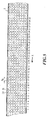
- eine schematische Draufsicht auf eine Einlagenmaterialbahn nach dem Ausstanzen.
- Fig. 1
- an inventive system in a schematic side view;
- Fig. 2
- the system of Figure 1 in a schematic plan view along the arrow II of Figure 1, wherein individual elements of the system of Figure 1 are omitted for the sake of simplicity.
- Fig. 3
- is a schematic half-sectional view of a coffee powder capsule, as it can be produced by the system of Figures 1 and 2.
- Fig. 4
- a schematic detailed view of insert material webs in the area of a punching device of the system of Figure 1 to explain the inventive method in a plan view;
- Fig. 5
- is a schematic plan view of an insert material web after punching.
In der Fig. 1 ist eine Anlage 1 gezeigt, mit der Einlagen (in Fig. 1 nicht dargestellt) aus
einer im wesentlichen bandförmigen Einlagenmaterialbahn 2 ausgestanzt und auf eine
im wesentlichen bandförmige Behältermaterialbahn 3 aufgebracht werden. Die
Einlagenmaterialbahn 2 wird mittels eines Antriebs 5 von einer Rolle 4 abgewickelt und
über eine Schlaufe 6 einer Stanz- und Siegelvorrichtung 7 zugeführt. Die lediglich im
Querschnitt dargestellte Behältermaterialbahn 3 verläuft senkrecht zur
Einlagenmaterialbahn 2.1 shows a
In der Stanz- und Siegelvorrichtung 7 werden mehrere Einlagen, die beispielsweise aus
einem selbstabdichtenden Kunststoffvlies bestehen können, gleichzeitig durch in einem
vorbestimmten Auftragsmuster an einem Stanzkopf 7a fest angeordnete Stempel 7b aus
der Einlagenmaterialbahn 2 ausgestanzt und von unten auf die Behältermaterialbahn 3
aufgesiegelt.In the punching and sealing
Über einen in Arbeitstakten getakteten Antrieb 8 wird die Einlagenmaterialbahn 2 aus
der Stanzvorrichtung 7 abgezogen und nach einer weiteren Schlaufe 9 in einer
angetriebenen Abfallrolle 10 aufgewickelt. Alternativ kann anstelle der Rolle 10 ein
Shredder 12 vorgesehen sein, in den die Einlagenmaterialbahn 2 nach dem getakteten
Antrieb 8 direkt geleitet wird.The
Die Rolle 4 kann durch die Antriebsvorrichtung 5 kontinuierlich mit gleichbleibender
Geschwindigkeit abgewickelt werden, während die getaktete Antriebseinrichtung 8 das
Bandmaterial aus der Schlaufe 6 in die Schlaufe 9 fördert. Die Schlaufe 6 dient somit
als Materialpuffer, um nicht die träge Masse der Rolle 4 im Arbeitstakt synchron zur
getakteten Antriebseinrichtung 8 bewegen zu müssen. The
Die Anlage 1 ist über ein Grundgestell 13 fest auf einem Boden 14 aufgestellt.The
Die Stanz- und Siegeleinrichtung 7 ist auf einem Schlitten 15 angeordnet, der gegenüber
dem Untergestell 13 beweglich ist. Der Schlitten 15 wird über eine Antriebsvorrichtung
16 quer zur Abwickelrichtung X der Einlagenmaterialbahn 2 verfahren. Durch einen
weiteren Antrieb 19 wird Stanzkopf 7a mit den Stempeln 7b taktweise in die
Einlagenmaterialbahn 2 bewegt, wodurch die Einlagen ausgestanzt und auf der
Behältermaterialbahn 3 aufgebracht werden. Der getaktete Antrieb 8 ist durch eine in
Fig. 1 nicht gezeigte elektronische Steuereinrichtung mit der Bewegung der Stempel 7b
synchronisiert.The punching and sealing
Alternativ kann die Stanz- und Siegeleinrichtung 7 auch stationär angeordnet sein und
die Materialrollen 4, 10 können mitsamt den Antrieben 5, 8 und den Schlaufen 6, 9 fest
am Schlitten 15 angeordnet sein und durch den Antrieb 16 bewegt werden. Um die
bewegten Massen zu verringern, können die Rollen 4, 10 aber auch stationär gegenüber
dem Untergestell 13 bleiben, und die Bewegung zwischen den Rollen und dem Schlitten
kann durch die Schlaufen 6, 9 aufgefangen werden.Alternatively, the punching and sealing
In Fig. 2 ist eine Draufsicht auf die Anlage der Fig. 1 in Richtung des Pfeils II
dargestellt, wobei der oberhalb der Behältermaterialbahn gelegene Teil der Stanz- und
Siegelvorrichtung 7, die Antriebseinrichtungen 5, 8 sowie die Schlaufen 6, 9 der
Übersicht halber nicht dargestellt sind.In Fig. 2 is a plan view of the system of FIG. 1 in the direction of arrow II
shown, the part of the punching and
Wie in Fig. 2 zu erkennen ist, weist die Anlage 1 zwei parallele Einlagenmaterialbahnen
2 und 2' am Schlitten 15 auf.As can be seen in FIG. 2, the
Beide Einlagenmaterialbahnen 2, 2' verlaufen im Wesentlichen senkrecht zur
Behältermaterialbahn 3.Both insert
Die Behältermaterialbahn 3, beispielsweise ein Aluminiumband, wird von einer Rolle
21 abgewickelt und dann durch die Anlage 1 geführt. In der Anlage 1 überlappen sich
im Bereich der Stanz- und Siegelvorrichtung 7, wo die kreisförmigen Einlagen 22 auf
die Behältermaterialbahn 3 aufgebracht werden, die Einlagenmaterialbahnen 2, 2' und
die Behältermaterialbahn 3. Nach dem Aufbringen der Einlagen 22 werden in einer
Umformanlage 23 aus der Behältermaterialbahn 3 Behälter (in Fig. 2 nicht dargestellt)
durch Ausstanzen und Umformen, wie beispielsweise Blasformen oder Tiefziehen,
erzeugt. Der Rest der Behältermaterialbahn 3 wird schliesslich aufgewickelt und
entsorgt bzw. wiederaufbereitet.The
In der Fig. 2 ist das Auftragsmuster 24 zu erkennen, in dem die Einlagen 22 in der
Anlage 1 ausgestanzt und auf die Behältermaterialbahn 3 aufgebracht werden. Bei der
Ausführungsform der Fig. 2 besteht das Auftragsmuster 24 aus zwei Reihen von in
Richtung X der Einlagenmaterialbahnen beabstandeten Stanzpositionen 25. Die beiden
Reihen von Stanzpositionen 25 sind dabei gegeneinander so versetzt, dass jeweils eine
Stanzposition 25 der einen Reihe in Richtung quer zur Einlagenmaterialbahn mittig
zwischen zwei Stanzpositionen 25 der anderen Reihe liegt.2 shows the
Das Auftragsmuster 24 bzw. die Anzahl und die Anordnung der Stanzpositionen 25 im
Auftragsmuster 24 entspricht dem Muster 24' der Umformpositionen 25', in dem in der
Umformanlage 23 die Behälter gleichzeitig ausgeformt werden. Bei der erläuterten
Ausführungsform weist das Auftragsmuster 24 insgesamt zwölf Stanzpositionen 25 auf,
wobei jeder Stanzposition 25 eine Umformposition 25' zugeordnet ist.The
Wie aus der Fig. 2 hervorgeht, ist der Durchmesser RE der Einlagen 22 kleiner als der
Durchmesser RB des Bereichs 25', aus dem die Behälter geformt werden. Deswegen
beträgt der Abstand der Stanzpositionen 25 bzw. der Einlagen 22 innerhalb des
Auftragsmusters 24 ein Mehrfaches des Durchmessers der Stanzpositionen bzw.
Einlagen 22. Jede Einlage 22 liegt dabei mittig in einer Umformposition 25'.As can be seen from FIG. 2, the diameter R E of the
Die Fig. 3 zeigt einen Behälter 26, wie er durch die in der Fig. 1 und 2 gezeigte Anlage
hergestellt wird, im Halbschnitt. Der Behälter 26 stellt eine Kaffeepulver-Kapsel für
Kaffeeautomaten dar.Fig. 3 shows a
Der Behälter 26 ist im wesentlichen becher- oder napfförmig und weist mittig am
Boden eine Einlage 22 aus Vliesmaterial auf. Die Öffnung des Behälters ist von einem
sich radial erstreckenden Kragen 28 umgrenzt, an dem nach dem Befüllen der Kapsel
mit Kaffeepulver eine Siegelfolie (nicht gezeigt) angebracht wird. Die Wand des
Behälters 26 weist eine leicht faltenförmige Verformungsstruktur 29 auf, die im Zuge
der plastischen Verformung beim Tiefziehen entsteht. The
Im Folgenden wird der erfindungsgemässe Stanzvorgang mit Bezug auf die Fig. 4 erläutert.The punching process according to the invention is described below with reference to FIG. 4 explained.
In Fig. 4 sind unter Weglassung der Stanz- und Siegelvorrichtung 7 die beiden
Einlagenmaterialbahnen 2' und 2" sowie schematisch die Behältermaterialbahn 3 im
Bereich ihrer Überlappung gezeigt. Bei der folgenden Beschreibung wird ferner
lediglich auf Relativbewegungen zwischen den Stempeln 7b der Stanzvorrichtung 7 und
der Einlagenmaterialbahn 2', 2" eingegangen, wobei diese Relativbewegungen durch
eine Bewegung der Stanzvorrichtung 7 oder durch eine Bewegung der
Einlagenmaterialbahn 2', 2" gegenüber der Behältermaterialbahn 3 erreicht werden
können.4, the two are omitted, the punching and sealing
Mit der Anlage 1 werden die Einlagen 22 in sich wiederholenden Stanzzyklen auf die
Behältermaterialbahn 3 aufgetragen. Jeder Stanzzyklus besteht dabei aus einer
Aufeinanderfolge von Arbeitstakten, wobei während jeweils eines Arbeitstaktes die
Einlagen 22 eines Auftragsmusters 24 gleichzeitig auf die Behältermaterialbahn
aufgetragen werden und anschliessend eine Vorschubbewegung zur nächsten freien
Stanzposition auf der Einlagenmaterialbahn 2, 2' erfolgt.With the
In Fig. 4 sind mit dem Bezugszeichen 25-1 die Stanzpositionen des Auftragsmusters 24
im ersten Arbeitstakt eines Stanzzyklus gekennzeichnet und gepunktet gefüllt
dargestellt. Das Auftragsmuster 24 der Fig. 4 ist identisch dem in der Fig. 2
dargestellten Auftragsmuster 24.In FIG. 4, reference numbers 25-1 are the punching positions of the
Die Stanzpositionen 25-1 sind im Auftragsmuster 24 jeweils so voneinander
beabstandet, dass zwischen zwei in Bahnrichtung X der Einlagenmaterialbahn 2
benachbarten, im Abstand Px voneinander angeordneten Stanzpositionen 25-1 jeweils
drei weitere, voneinander beabstandete Stanzpositionen ausgestanzt werden können.
Zwischen zwei in Richtung Y quer zur Einlagenmaterialbahn 2, 2' um Py
beabstandeten, benachbarten Stanzpositionen 25-1 eines Auftragsmusters 24 können
ebenfalls drei Einlagen 22 beabstandet ausgestanzt werden. Zwischen den anfänglichen
Stanzpositionen 25-1 lässt sich somit eine gedachte Fläche 31 einschreiben, innerhalb
der fünfzehn Einlagen 22 ausgestanzt werden können, wenn man die anfängliche
Stanzposition nicht mitzählt. Die Fläche 31 ist in Fig. 4 für zwei anfängliche
Stanzpositionen 25-1 beispielhaft schraffiert dargestellt. Natürlich ist jeder
Stanzposition des Auftragsmusters 24 eine solche Fläche 31 zugeordnet.The punching positions 25-1 are spaced apart from one another in the
Der Abstand jeweils zwischen den Stanzpositionen 25-1 im Auftragsmuster 24, die
Anzahl der Stanzpositionen im Auftragsmuster 24 und die Anzahl der zwischen den
Stanzpositionen 25-1 angeordneten Einlagen 22 ist lediglich beispielhaft angegeben und
kann je nach Art der Anwendung variieren.The distance between the punch positions 25-1 in the
Erfindungsgemäss werden die Stanzvorrichtung 7 und die Einlagenmaterialbahn 2
relativ zueinander entlang einer Bahn 32 verfahren, die in die Fläche 31 eingeschrieben
ist. Entlang der Bahn werden zu jedem Arbeitstakt die Einlagen 22 eines
Auftragsmusters 24 ausgestanzt. Bei der dargestellten Ausführungsform ist die Fläche
31 ein Quadrat aus 4 x 4 Stanzpositionen 25, wobei das Quadrat mit zwei Seiten parallel
zur Einlagenmaterialbahn 2 ausgerichtet ist. Je nach Anwendung und Auftragsmuster
kann die Fläche 31 jedoch auch andere Formen und Grössen aufweisen.According to the invention, the
Die Bahn 32 ist so auf die Fläche 31 gelegt, dass die Fläche 31 möglichst vollständig
abgefahren wird und dass die Einlagenmaterialbahn 2 selbst nur möglichst selten und
möglichst nur in einer Richtung, vorzugsweise der Abwickelrichtung X, bewegt werden
muss.The
Dies wird bei der Ausfiihrungsform der Fig. 4 dadurch erreicht, dass ausgehend von der
ersten Stanzposition 25-1 des Stanzzyklus die Bahn 32 zunächst quer zur Richtung X
der Einlagenmaterialbahn 2 verläuft. Auf dieser Teilstrecke ist keine Bewegung der
Einlagenmaterialbahn 2 in Abwickelrichtung notwendig. Nach einer Strecke AY sind
die zweiten Stanzpositionen 25-2 entlang der Bahn 32 erreicht und im nächsten
Arbeitstakt wird an diesen Stellen erneut ein Auftragsmuster 24 aus-gestanzt und
aufgetragen.In the embodiment of FIG. 4, this is achieved in that, starting from the first punching position 25-1 of the punching cycle, the
Damit die Einlagenmaterialbahn 2 auch nach dem Ausstanzen der Einlagen 22 eine
ausreichende Festigkeit aufweist, sind die Stanzpositionen 25 entlang der Bahn 32 so
voneinander beabstandet, dass Stege zwischen den Ausstanzungen stehen bleiben. Die
Breite dieser Stege kann vorzugsweise zwischen 5 % und 15 % des kleinsten
Durchmessers der Ausstanzungen betragen. So that the
Nach dem Ausstanzen der zweiten Stanzpositionen 25-2 innerhalb eines Stanzzyklus
werden in derselben Richtung quer zur Einlagenmaterialbahn 2 in den folgenden
Arbeitstakten jeweils nach einer Bewegung um Ay weitere Stanzpositionen 25-3, 25-4
ausgestanzt, bis die Bahnen 32 die Ränder der jeweiligen Flächen 31 erreichen. Wie in
der Fig. 4 zu erkennen ist, liegen die Ränder der Flächen 31 jeweils vor der zweiten
Reihe der ersten Stanzpositionen 25-1, bzw. vor dem Rand der Einlagenmaterialbahn 2,
2'.After punching out the second punching positions 25-2 within a punching cycle, further punching positions 25-3, 25-4 are punched out in the same direction transverse to the
An dem in Richtung Y quer zur Einlagenmaterialbahn gelegenen Ende der Fläche 31
wird die Einlagenmaterialbahn 2 nach dem Ausstanzen der Stanzpositionen 25-4 im
nächsten Arbeitstakt ohne eine Querbewegung zwischen Einlagenmaterialbahn 2 und
Stanzvorrichtung 7 um die Länge Ax abgewickelt, sodass die fünfte Stanzposition 25-5
in Einlagenmaterialbahnrichtung X von der vorangegangenen vierten Stanzposition 25-4
um Ax beabstandet ist.At the end of the
Um Zugkräfte besser aufnehmen zu können, kann der Abstand Ax der Mittelpunkte
zweier in Bahnrichtung benachbarter Stanzpositionen 25 grösser sein als der Abstand
Ay der Mittelpunkte zweier in Richtung quer zur Bahnrichtung benachbarter
Stanzpositionen 25. Dadurch sind die in Abwickelrichtung X gelegenen Stege breiter
und können die Zugkräfte besser aufnehmen. Der Abstand Ax kann zwischen 5 % bis 15
% des Einlagendurchmessers betragen.In order to be able to absorb tensile forces better, the distance A x between the center points of two
Die Abwickelgeschwindigkeit der Einlagenmaterialbahn 2, die durch den getakteten
Antrieb 8 (vgl. Fig. 1) erzeugt wird, in Richtung der Strecke AY beträgt dabei zwischen
100 und 200 mm/s.The unwinding speed of the
Nach Ausstanzen der fünften Stanzpositionen 25-5 werden die Einlagenmaterialbahn 2
und die Stanzvorrichtung 7 entlang der Bahn 32 relativ zueinander wieder in Richtung
quer zur Einlagenmaterialbahnrichtung zurück bis zu den Stanzpositionen 25-8 auf der
Höhe der ersten Stanzposition 25-1 bewegt. Auf dieser Teilstrecke der Bahn 32 findet
wiederum lediglich ein Vorschub durch den Schlitten 15 jeweils um Ay statt.After the fifth punching positions 25-5 have been punched out, the
Nach dem Ausstanzen der Stanzpositionen 25-8 wird die Einlagenmaterialbahn 2
wieder um Ax abgewickelt und es beginnt eine neue Querbewegung mit vier
Arbeitstakten, bis wiederum der Rand der Fläche 32 erreicht ist. Auf diese Weise
erhalten die Bahnen 31 eine zickzackförmige oder mäanderförmige Form, die sich
jeweils zwischen den quer zur Bahnrichtung gelegenen Rändern der Flächen 31 hin und
her bewegt. Eine Abwickelbewegung der Einlagenmaterialbahn 2 findet dabei nur statt,
wenn die Bahnen 32 den Rand der Flächen 31 erreicht hat.After the punching positions 25-8 have been punched out, the
Insgesamt werden auf diese Weise im ersten Stanzzyklus sechzehn Stanzpositionen 25-1
bis 25-16 pro Fläche 31 angefahren.In this way, a total of sixteen punching positions 25-1 become in the first punching cycle
approached to 25-16 per
Ist am Ende des Stanzzyklus jeweils die letzte Stanzposition 25-16 des Auftragsmusters
24 innerhalb der jeweiligen Fläche 31 angefahren, so ist der gesamte Stanzbereich 33
ausgestanzt, dessen Grenzen durch doppelt strichpunktierte Linsen in Fig. 4 angedeutet
sind. Für den nächsten Stanzzyklus müssen daher die neuen Anfangspositionen 25-1'
des nächsten Stanzzyklus an die Stelle der Anfangspositionen der ersten
Stanzpositionen 25-1 des ersten Stanzzyklus verfahren werden. Die dazu von der
Einlagenmaterialbahn 2 abzuwickelnde Länge Vx entspricht der Summe aus dem
Abstand zwischen den beiden in Bahnrichtung gelegenen äussersten Stanzpositionen 25
und einem Abstand Ax zwischen zwei Stanzpositionen in Abwickelrichtung.If at the end of the punching cycle the last punching position 25-16 of the
Da die mechanischen Eigenschaften der Einlagenmaterialbahn 2 nur ein langsames
Abwickeln erlauben, ist eine zweite Einlagenmaterialbahn 2' vorgesehen, die in einem
Abstand By parallel zur ersten Einlagenmaterialbahn 2 auf dem in Fig. 4 nicht
dargestellten Schlitten 15 angeordnet ist.Since the mechanical properties of the
Während die erste Einlagenmaterialbahn 2 um den Betrag Vx abgewickelt wird, wird
der Schlitten 15 innerhalb eines Arbeitstaktes mit den beiden Einlagenmaterialbahnen 2,
2' in Richtung des Pfeils 34 um einen Betrag VY in Richtung quer zu den
Einlagenmaterialbahnen 2, 2' verfahren, bis sich in Stanzrichtung die Stanzvorrichtung
7 und die zweite Einlagenmaterialbahn 2' überlappen.While the first
Durch den Schlittenvorschub um Vy kommen neue erste Stanzpositionen 25-1a auf der
zweiten Einlagenmaterialbahn 2' an den Stellen der anfänglichen ersten Stanzpositionen
25-1 auf der ersten Einlagenmaterialbahn 2' zwischen der Stanzvorrichtung 7 und der
Behältermaterialbahn 3 zu liegen. Ausgehend von diesen Stanzpositionen 25-1a wird
dann auf der zweiten Einlagenmaterialbahn 2' die Bahn 32 in einem zweiten
Stanzzyklus wie zuvor bei der ersten Einlagenmaterialbahn 2 in sechzehn Arbeitstakten
abgefahren. Nachdem auf der zweiten Einlagenmaterialbahn 2' am Ende der Bahn 32,
d.h. am Ende des zweiten Stanzzyklus, die letzte Stanzposition 25-16a vom
Auftragsmuster 24 erreicht wurde, ist auch bei der zweiten Einlagenmaterialbahn der
Stanzbereich ausgestanzt. Nun muss die zweite Einlagenmaterialbahn 2' um Vx
abgewickelt werden.Due to the carriage advance by V y , new first punching positions 25-1a on the second insert material web 2 'come to lie at the locations of the initial first punching positions 25-1 on the first insert material web 2' between the punching
Während der Abwickelbewegung der zweiten Einlagenmaterialbahn 2' wird der
Schlitten 15 innerhalb eines Arbeitstaktes in umgekehrter Richtung zum Pfeil 34 um VY
bewegt, sodass wieder die erste Einlagenmaterialbahn 2 zwischen der Stanzvorrichtung
7 und der Behältermaterialbahn 3 zu liegen kommt. Da inzwischen die erste
Einlagenmaterialbahn 2 um Vx weitergeschaltet wurde, beginnt nun ein weiterer
Stanzzyklus an den ersten Stanzpositionen 25-1' des dritten Arbeitszyklus in einem
neuen Stanzbereich. Gleichzeitig wird die zweite Einlagenmaterialbahn 2' um Vy
abgewickelt.During the unwinding movement of the second
Auf diese Weise ergibt sich bei einer ausgestanzten Einlagenmaterialbahn 2, wie sie in
Fig. 5 schematisch dargestellt ist, ein Stanzmuster, bei dem die Mittelpunkte der
Ausstanzungen auf Linien 34, 35 liegen, die quer und parallel zur Bahnrichtung
verlaufen. Der Ausnutzungsgrad, d. h. der Anteil der ausgestanzten Fläche an der
Gesamtfläche, liegt dabei zwischen 50 % und 55 %.This results in a punched-out
Die Durchmesser der Ausstanzungen betragen bei den dargestellten Vlieseinlagen für Kaffeepulver-Kapseln etwa 10 mm bis 50 mm, vorzugsweise etwa 20 mm, der Abstand Ax in Bahnrichtung zwischen den Ausstanzungen beträgt zwischen 25 und 30 mm, der Abstand Ay quer zur Bahnrichtung zwischen 22 und 26 mm.The diameters of the punched-out areas in the illustrated nonwoven inserts for coffee powder capsules are approximately 10 mm to 50 mm, preferably approximately 20 mm, the distance A x in the web direction between the punched-out areas is between 25 and 30 mm, the distance A y across the web direction is between 22 and 26 mm.
Mit der erfindungsgemässen Anlage und dem erfindungsgemässen Verfahren lassen sich Taktraten von mindestens 70 - 100/min bei einer geringeren Abfallmenge erzielen.Leave with the system according to the invention and the method according to the invention clock rates of at least 70-100 / min can be achieved with a lower amount of waste.
Typischerweise können bei der Verwendung einer Einlagematerialbahn aus
Polyurethanvlies bei Verwendung dieses Verfahrens vergleichsweise hohe
Transportgeschwindigkeiten der Behältermaterialbahn realisiert werden, wobei konkret
ein Polyurethanvlies aus Estane® mit einem Flächengewicht von 50 Gramm pro
Quadratmeter (DIN 53854, d = 100), einer Reisskraft in Längsrichtung von 20 N/5cm
und in Querrichtung von 14 N/5cm (DIN/EN 29073 T3), einer Dehnung in
Längsrichtung von 210% und in Querrichtung von 265% (DIN/EN 29073 T3), bei einer
Luftdurchlässigkeit von 450 l/m2/s (DIN 53887,200 Pa), einer Porengrösse von minimal
17.9 µm, maximal 29 µm einem Durchschnitt von 23 µm (Coulter Porometer) und bei
einer Dicke von 0.16 mm (DIN/EN ISO 9073-2:1997-02 Punkt 5.1), und bei einer
Schmelztemperatur von 175 bis 180 Grad Celsius . Zwischen den einzelnen Schritten
25-1, 25-2, 25-3 ... innerhalb der Bahn 32 können in Y-Richtung bei einem
Transportweg von 24.75 mm Geschwindigkeiten von 165 mm/s realisiert werden
(Schlittenbewegung), und in X-Richtung bei einem Transportweg von 28.58 mm
Geschwindigkeiten von 190 mm/s (Vorschub des Filtermaterials). Beim Wechsel vom
ersten Band 2' zu zweiten Band 2" kann eine Schlittenbewegung mit einer
Geschwindigkeit von 0.93m/s durchgeführt werden. Während der Bearbeitung des
anderen Bands kann das erste Band in schonender Weise mit einer
Vorschubgeschwindigkeit von 107.17 mm/s in X-Richtung transportiert werden, ohne
dass dabei der Prozess unterbrochen werden muss.Typically, when using an interlining made of polyurethane fleece, comparatively high transport speeds of the container material web can be achieved using this method, specifically a polyurethane fleece made from Estane® with a basis weight of 50 grams per square meter (DIN 53854, d = 100), a tensile strength in the longitudinal direction of 20 N / 5cm and in the transverse direction of 14 N / 5cm (DIN / EN 29073 T3), an elongation in the longitudinal direction of 210% and in the transverse direction of 265% (DIN / EN 29073 T3), with an air permeability of 450 l / m 2 / s (DIN 53887,200 Pa), a pore size of at least 17.9 µm, a maximum of 29 µm, an average of 23 µm (Coulter Porometer) and a thickness of 0.16 mm (DIN / EN ISO 9073-2: 1997-02 point 5.1 ), and at a melting temperature of 175 to 180 degrees Celsius. Between the individual steps 25-1, 25-2, 25-3 ... within the
Die weiter oben genannten Taktraten lassten sich so realisieren bei einer Siegelzeit von 200ms, und bei einer Bewegung des Zeit für Filter- und Schlittentransport von 300 ms. Daraus ergibt sich eine Taktzeit pro Hub von 705.88 ms und eine Taktleistung von 61200 Kapseln/h. The clock rates mentioned above could be realized with a sealing time of 200ms, and with a movement of the time for filter and carriage transport of 300 ms. This results in a cycle time of 705.88 ms per stroke and a cycle power of 61200 capsules / h.
- 11
- Anlageinvestment
- 22
- EinlagenmaterialbahnDeposits web
- 33
- BehältermaterialbahnContainer material web
- 44
- Rollerole
- 55
- Antriebdrive
- 66
- Schlaufeloop
- 77
- Stanz- und SiegelvorrichtungStamping and sealing device
- 7a7a
- Stanzkopfpunching head
- 7b7b
- Stempelstamp
- 88th
- Antriebdrive
- 99
- Schlaufeloop
- 1010
- Abfallrollewaste roll
- 1212
- ShredderShredder
- 1313
- Grundgestell, UntergestellBase frame, base frame
- 1414
- Bodenground
- 1515
- Schlittencarriage
- 1616
- Antriebsvorrichtungdriving device
- 1919
- Antriebdrive
- 2121
- Rollerole
- 2222
- kreisförmige Einlagencircular inlays
- 2323
- Umformanlageforming plant
- 2424
- Auftragsmuster order patterns
- 2525
- Stanzpositionenpunching positions
- 25-125-1
- Stanzpositionen erster ArbeitstaktPunching positions first work cycle
- 25-225-2
-
Stanzpositionen zweiter Arbeitstakt
...Stamping positions second work cycle
... - 25-1625-16
- Stanzpositionen letzte Arbeitstakt eines ZyklusDie positions last cycle of a cycle
- 25'25 '
- UmformpositionenUmformpositionen
- 2626
- Behältercontainer
- 2727
- Bodenground
- 2828
- Kragencollar
- 2929
- Verformungsstrukturdeformation structure
- 3131
- Flächearea
- 3232
- Bahntrain
- 3333
- Stanzbereichpunch area
- XX
- Abwickelrichtungunwinding
- RE R E
-
Durchmesser der Einlagen 22
Insert diameter 22 - RB R B
- Durchmesser des Bereichs 25'Area 25 'diameter
- Px,Py P x , P y
- Abstanddistance
- Vx V x
- abzuwickelnde LängeLength to be unwound
Claims (25)
dadurch gekennzeichnet, dass
die Einlagen (22) vor dem Umformen der becherförmigen Behälter (26) an den Stellen aufgebracht werden, an denen die Behälter in einem nachfolgenden Arbeitsgang durch Umformen gefertigt werden.Method for producing cup-shaped containers (26) provided with an insert (22), the cup-shaped containers (26) first being punched out of a container material web (3) and then shaped in a forming process,
characterized in that
before the shaping of the cup-shaped containers (26), the inserts (22) are applied at the locations at which the containers are manufactured by shaping in a subsequent operation.
Applications Claiming Priority (2)
| Application Number | Priority Date | Filing Date | Title |
|---|---|---|---|
| CH7392003 | 2003-04-25 | ||
| CH7392003 | 2003-04-25 |
Publications (2)
| Publication Number | Publication Date |
|---|---|
| EP1471012A2 true EP1471012A2 (en) | 2004-10-27 |
| EP1471012A3 EP1471012A3 (en) | 2005-01-12 |
Family
ID=32932335
Family Applications (1)
| Application Number | Title | Priority Date | Filing Date |
|---|---|---|---|
| EP04405230A Withdrawn EP1471012A3 (en) | 2003-04-25 | 2004-04-15 | Method and apparatus for manufacturing cup-shaped containers from material webs |
Country Status (1)
| Country | Link |
|---|---|
| EP (1) | EP1471012A3 (en) |
Cited By (10)
| Publication number | Priority date | Publication date | Assignee | Title |
|---|---|---|---|---|
| EP1568451A1 (en) * | 2004-02-27 | 2005-08-31 | Ideacorp AG | Method and apparatus for punching a filtering medium |
| EP1849715A1 (en) * | 2006-04-24 | 2007-10-31 | Nestec S.A. | Capsule for preparation of a beverage with a sealing member attached thereto and method of producing the same |
| WO2012010317A1 (en) * | 2010-07-22 | 2012-01-26 | Krüger Gmbh & Co. Kg | Portion capsule having an identifier |
| US10343838B2 (en) | 2012-06-18 | 2019-07-09 | K-Fee System Gmbh | Portion capsule and use of same for producing a beverage |
| US10472165B2 (en) | 2012-12-14 | 2019-11-12 | K-Fee System Gmbh | Portion capsule and method for producing a beverage by means of a portion capsule |
| US10669093B2 (en) | 2015-02-27 | 2020-06-02 | K-Fee System Gmbh | Single serve capsule comprising a filter element connected thereto by sealing |
| US10737876B2 (en) | 2015-07-13 | 2020-08-11 | K-Fee System Gmbh | Filter element having a cut-out |
| EP3792197A1 (en) * | 2010-09-22 | 2021-03-17 | K-fee System GmbH | Portion capsule and method for producing a beverage with a portion capsule |
| US11045035B2 (en) | 2015-09-18 | 2021-06-29 | K-Fee System Gmbh | Adapter for a single serve capsule |
| US11084650B2 (en) | 2015-06-10 | 2021-08-10 | K-Fee System Gmbh | Portion capsule with a three-ply nonwoven fabric |
Citations (4)
| Publication number | Priority date | Publication date | Assignee | Title |
|---|---|---|---|---|
| US4616766A (en) * | 1983-10-17 | 1986-10-14 | Showa Denko Kabushiki Kaisha | Can-like container |
| US5298267A (en) * | 1991-07-05 | 1994-03-29 | The Procter & Gamble Company | Coffee filter pack |
| US20020015768A1 (en) * | 1999-03-18 | 2002-02-07 | Petr Masek | Sealed cartridge for making a beverage |
| EP1190959A1 (en) * | 2000-09-26 | 2002-03-27 | Societe Des Produits Nestle S.A. | Capsule for beverage preparation with extraction under pressure |
-
2004
- 2004-04-15 EP EP04405230A patent/EP1471012A3/en not_active Withdrawn
Patent Citations (4)
| Publication number | Priority date | Publication date | Assignee | Title |
|---|---|---|---|---|
| US4616766A (en) * | 1983-10-17 | 1986-10-14 | Showa Denko Kabushiki Kaisha | Can-like container |
| US5298267A (en) * | 1991-07-05 | 1994-03-29 | The Procter & Gamble Company | Coffee filter pack |
| US20020015768A1 (en) * | 1999-03-18 | 2002-02-07 | Petr Masek | Sealed cartridge for making a beverage |
| EP1190959A1 (en) * | 2000-09-26 | 2002-03-27 | Societe Des Produits Nestle S.A. | Capsule for beverage preparation with extraction under pressure |
Cited By (37)
| Publication number | Priority date | Publication date | Assignee | Title |
|---|---|---|---|---|
| EP1914048A3 (en) * | 2004-02-27 | 2008-12-10 | Nestec S.A. | Method and device for punching a filter material |
| EP1568451A1 (en) * | 2004-02-27 | 2005-08-31 | Ideacorp AG | Method and apparatus for punching a filtering medium |
| US8161866B2 (en) | 2006-04-24 | 2012-04-24 | Nestec S.A. | Capsule for preparation of a beverage with a sealing member attached thereto and method of producing the same |
| EP1849715A1 (en) * | 2006-04-24 | 2007-10-31 | Nestec S.A. | Capsule for preparation of a beverage with a sealing member attached thereto and method of producing the same |
| WO2007122206A1 (en) * | 2006-04-24 | 2007-11-01 | Nestec S.A. | Capsule for preparation of a beverage with a sealing member attached thereto and method of producing the same |
| CN101432207B (en) * | 2006-04-24 | 2010-11-24 | 雀巢产品技术援助有限公司 | Capsule for preparation of a beverage with a sealing member attached thereto and method of producing the same |
| US11465830B2 (en) | 2010-07-22 | 2022-10-11 | K-Fee System Gmbh | Portion capsule having an identifier |
| US10870531B2 (en) | 2010-07-22 | 2020-12-22 | K-Fee System Gmbh | Portion capsule having an identifier |
| RU2581002C2 (en) * | 2010-07-22 | 2016-04-10 | К-Фее Зюстем Гмбх | Portioned capsule with identifier |
| CN103476686B (en) * | 2010-07-22 | 2016-08-31 | K-Fee系统股份有限公司 | There is the distribution capsule of identifier |
| CN105996782A (en) * | 2010-07-22 | 2016-10-12 | K-Fee系统股份有限公司 | Portion capsule having an identifier |
| US11667465B2 (en) | 2010-07-22 | 2023-06-06 | K-Fee System Gmbh | Portion capsule having an identifier |
| US11554910B2 (en) | 2010-07-22 | 2023-01-17 | K-Fee System Gmbh | Portion capsule having an identifier |
| US11548722B2 (en) | 2010-07-22 | 2023-01-10 | K-Fee System Gmbh | Portion capsule having an identifier |
| CN103476686A (en) * | 2010-07-22 | 2013-12-25 | K-Fee系统股份有限公司 | Portion capsule having an identifier |
| US10858176B2 (en) | 2010-07-22 | 2020-12-08 | K-Fee System Gmbh | Portion capsule having an identifier |
| US10858177B2 (en) | 2010-07-22 | 2020-12-08 | K-Fee System Gmbh | Portion capsule having an identifier |
| US11465829B2 (en) | 2010-07-22 | 2022-10-11 | K-Fee System Gmbh | Portion capsule having an identifier |
| WO2012010317A1 (en) * | 2010-07-22 | 2012-01-26 | Krüger Gmbh & Co. Kg | Portion capsule having an identifier |
| US20210086986A1 (en) | 2010-07-22 | 2021-03-25 | K-Fee System Gmbh | Portion capsule having an identifier |
| US10994923B2 (en) | 2010-07-22 | 2021-05-04 | K-Fee System Gmbh | Portion capsule having an identifier |
| US11919703B2 (en) | 2010-07-22 | 2024-03-05 | K-Fee System Gmbh | Portion capsule having an identifier |
| US11542094B2 (en) | 2010-07-22 | 2023-01-03 | K-Fee System Gmbh | Portion capsule having an identifier |
| US11230430B2 (en) | 2010-07-22 | 2022-01-25 | K-Fee System Gmbh | Portion capsule having an identifier |
| US11254491B2 (en) | 2010-07-22 | 2022-02-22 | K-Fee System Gmbh | Portion capsule having an identifier |
| US11820586B2 (en) | 2010-07-22 | 2023-11-21 | K-Fee System Gmbh | Portion capsule having an identifier |
| EP4056499A1 (en) * | 2010-09-22 | 2022-09-14 | K-fee System GmbH | Portion capsule and method for producing a beverage with a portion capsule |
| EP3792197A1 (en) * | 2010-09-22 | 2021-03-17 | K-fee System GmbH | Portion capsule and method for producing a beverage with a portion capsule |
| US11312567B2 (en) | 2012-06-18 | 2022-04-26 | K-Fee System Gmbh | Portion and method for producing a beverage by means of a portion capsule |
| US11702276B2 (en) | 2012-06-18 | 2023-07-18 | K-Fee System Gmbh | Portion capsule for preparing a beverage |
| US10343838B2 (en) | 2012-06-18 | 2019-07-09 | K-Fee System Gmbh | Portion capsule and use of same for producing a beverage |
| US10472165B2 (en) | 2012-12-14 | 2019-11-12 | K-Fee System Gmbh | Portion capsule and method for producing a beverage by means of a portion capsule |
| US10669093B2 (en) | 2015-02-27 | 2020-06-02 | K-Fee System Gmbh | Single serve capsule comprising a filter element connected thereto by sealing |
| US11084650B2 (en) | 2015-06-10 | 2021-08-10 | K-Fee System Gmbh | Portion capsule with a three-ply nonwoven fabric |
| US10737876B2 (en) | 2015-07-13 | 2020-08-11 | K-Fee System Gmbh | Filter element having a cut-out |
| US11498750B2 (en) | 2015-07-13 | 2022-11-15 | Gcs German Capsule Solution Gmbh | Filter element having a cut-out |
| US11045035B2 (en) | 2015-09-18 | 2021-06-29 | K-Fee System Gmbh | Adapter for a single serve capsule |
Also Published As
| Publication number | Publication date |
|---|---|
| EP1471012A3 (en) | 2005-01-12 |
Similar Documents
| Publication | Publication Date | Title |
|---|---|---|
| DE19515517C2 (en) | Method and device for the continuous production of lengths from a strand of liquid-absorbent material and its use | |
| DD287451A5 (en) | FORM FILLING LOCKING MACHINE FOR THE AUTOMATIC MANUFACTURE OF A PREFERRED NUMBER OF FILLED AND SEALED FINISHED PACKAGING | |
| DE69813959T2 (en) | Packing of items packed with a plastic sheet, plastic sheet for packing a pack, and method of manufacturing the plastic sheet | |
| DE3637877A1 (en) | METHOD AND DEVICE FOR PRODUCING BAGS | |
| DE1296780B (en) | Method for producing a fabric-like network from a film made of thermoplastic material | |
| EP1046479A1 (en) | Apparatus for perforating and embossing web like materials | |
| EP2806986B1 (en) | Method and device for joining two metal strip ends | |
| EP1839825A1 (en) | Method and apparatus for producing perforated sheet material | |
| EP1471012A2 (en) | Method and apparatus for manufacturing cup-shaped containers from material webs | |
| DE2065712A1 (en) | DEEP DRAWING MACHINE FOR MANUFACTURING REINFORCED SIDE WALL CONTAINERS | |
| DE102010026801A1 (en) | Device for separating packages from a carrier web with blister bubbles arranged one behind the other | |
| EP2558231A1 (en) | Arrangement for forming a band loop and process and apparatus for producing tear-open lids | |
| EP2289660B1 (en) | Device and process of cutting TDS and ODF materials with two pairs of advancing rolls | |
| WO2017108415A1 (en) | Apparatus and process for producing nonwoven products using rotary punches | |
| DE3113951C2 (en) | Method and device for the production of funnel-shaped filter inserts with opening aids | |
| EP1568451B1 (en) | Method and apparatus for punching a filtering medium | |
| WO1990004062A1 (en) | Process and installation for producing flat textile bodies | |
| DE19751983B4 (en) | Web-shaped material with perforation, packaging made from the material, process for producing the perforation in the material and apparatus for carrying out the process | |
| DE2656421C2 (en) | ||
| DE60314567T2 (en) | Integrated molding process and machine for making non-demouldable cups | |
| DE10000297A1 (en) | Method and device for producing and wrapping a soft plastic body consisting of several individual portions, preferably a fat-containing product, such as butter, margarine or the like. | |
| DE2748228C2 (en) | Method for the continuous transport of individual punched parts for electrical devices punched out by a punch to a stacking device and device for carrying out the method | |
| DE4418063C2 (en) | Machine for producing deep-drawn cups with feet | |
| DE19509863A1 (en) | Procedure for manufacturing moulded items from paper or cardboard | |
| EP2014155B1 (en) | Method for producing cheese slices, cheese slices produced thereby and a device for carrying out the method |
Legal Events
| Date | Code | Title | Description |
|---|---|---|---|
| PUAI | Public reference made under article 153(3) epc to a published international application that has entered the european phase |
Free format text: ORIGINAL CODE: 0009012 |
|
| AK | Designated contracting states |
Kind code of ref document: A2 Designated state(s): AT BE BG CH CY CZ DE DK EE ES FI FR GB GR HU IE IT LI LU MC NL PL PT RO SE SI SK TR |
|
| AX | Request for extension of the european patent |
Extension state: AL HR LT LV MK |
|
| PUAL | Search report despatched |
Free format text: ORIGINAL CODE: 0009013 |
|
| AK | Designated contracting states |
Kind code of ref document: A3 Designated state(s): AT BE BG CH CY CZ DE DK EE ES FI FR GB GR HU IE IT LI LU MC NL PL PT RO SE SI SK TR |
|
| AX | Request for extension of the european patent |
Extension state: AL HR LT LV MK |
|
| 17P | Request for examination filed |
Effective date: 20050507 |
|
| AKX | Designation fees paid |
Designated state(s): AT BE BG CH CY CZ DE DK EE ES FI FR GB GR HU IE IT LI LU MC NL PL PT RO SE SI SK TR |
|
| RAP1 | Party data changed (applicant data changed or rights of an application transferred) |
Owner name: NESTEC S.A. |
|
| 17Q | First examination report despatched |
Effective date: 20120627 |
|
| STAA | Information on the status of an ep patent application or granted ep patent |
Free format text: STATUS: THE APPLICATION HAS BEEN WITHDRAWN |
|
| 18W | Application withdrawn |
Effective date: 20140108 |