TECHNICAL FIELD
-
The present invention relates to a deodorization technique
for an operation involving malodor, and more specifically to a
deodorization apparatus and a deodorization method suitably
applicable to a coating booth, etc.
BACKGROUND ART
-
As an example of an operation booth where an operation involving
malodor is conducted, a coating operation booth (hereinafter
referred to as a "coating booth") is known. An example of such a
coating booth is disclosed in JP 6-328025 A.
-
The coating booth disclosed in the above-mentioned publication
has, as deodorization equipment, a dust collecting filter for
collecting coating mist (a malodorous substance) generated during
coating operation, a water spray device for removing fine coating
mist that has not been collected by the dust collecting filter,
etc.
-
More specifically, the air in the operation booth is sucked
in by an air intake fan to collect coating mist suspended in the
operation booth by the dust collecting filter. Then, to remove the
fine coating mist in the air that has not been collected by the
dust collecting filter, water is sprayed from the water spray device
into the air. Through adhesion of the sprayed water to the fine
coating mist, the remaining fine coating mist is removed from the
air. At the bottom of the booth, there is installed a vessel, and
the water mixed with fine coating mist (contaminated water) drips
into the vessel and is gathered therein. The contaminated water
in the vessel is separated afterwards into water and fine coating
mist by using a contaminated water processing apparatus such as
a centrifugal separator.
-
In this way, in the conventional coating booth, coating mist
(inclusive of fine coating mist) constituting the malodorous
substance is caught by the dust collecting filter or the water spray
device to suppress the malodor in the operation booth. The
contaminated water mixed with fine coating mist is separated and
purified by the contaminated water processing apparatus.
-
Incidentally, a study made by the inventors of the present
invention have revealed various points to be improved regarding
the above deodorization method.
-
First, with regard to the water spray, it is necessary to draw
water into the water spray device, install a vessel for receiving
the water, and to provide a contaminated water processing apparatus,
etc. separately from the coating booth apparatus main body, resulting
in high initial equipment cost (initial investment) for the coating
booth. Further, it is also necessary to periodically repeat
troublesome maintenance operations involving water treatment, such
as the cleaning of the vessel and the cleaning of the interior of
the contaminated processing apparatus.
-
Further, while effective in removing fine coating mist, the
water spray did not prove so effective in deodorizing a gaseous
malodorous substance (e.g., a solvent like thinner). Further, to
keep the running cost low, water once sprayed is usually utilized
again as spray water, which means as the number of times that the
water is used increases, the water itself gradually takes onmalodor.
-
The present invention has beenmade in view of the above problems
in the prior-art technique. It is an obj ect of the present invention
to provide a deodorization apparatus and a deodorization method
enhanced in deodorizing efficiency and reduced in initial investment
and running cost.
DISCLOSURE OF THE INVENTION
-
A deodorization apparatus according to the present invention
is characterized by including: an intake port for taking in a gas
with malodor; a deodorant supply device for supplying deodorant
into the gas taken in through the intake port; an exhaust port for
discharging the gas taken in through the intake port; an airflow
forming device for forming an airflow from the intake port to the
exhaust port; and a filter which removes a malodorous substance
from the gas with malodor together with the deodorant prior to exhaust
through the exhaust port.
-
In the deodorization apparatus of the present invention,
constructed as described above, a gas with malodor is first taken
in through the intake port. Then, deodorant is supplied to the gas
with malodor by the deodorant supply device. The malodorous
substance in the air flows toward the discharge port while adhering
to the deodorant, and flows into the filter prior to discharge through
the discharge port. The malodorous substance is then collected by
the filter together with the deodorant.
-
That is, in the present invention, the malodorous substance
is sent along in an airflow while adhering to the deodorant, and
is collected by the filter together with the deodorant. Thus, it
is possible to suppress malodor without having to provide any
large-scale equipment, such as a vessel and a contaminated water
processing apparatus. Further, a stable deodorization efficiency
can be maintained by an easy operation of filter replacement. Further,
since the malodorous substance is caught by using deodorant,
deodorization can be effected efficiently also on a gaseous
malodorous substance. There are no particular limitations
regarding the deodorant as long as it can be diffused and supplied
into a gas, and not only a liquid deodorant but also a powder deodorant
can be used.
-
Further, the deodorization apparatus may be constructed such
that the deodorization apparatus includes a booth main body for
restraining diffusion of malodor, and that the intake port is open
to an interior of the booth main body. With this construction,
malodor diffusion is suppressed within the booth main body, and
the malodor in the booth main body is deodorized by the deodorization
apparatus.
-
Further, the deodorization apparatus may be constructed to
include a moving device for moving a collecting surface of the filter
for collecting the deodorant and the malodorous substance. Further,
inmoving the collecting surface, the moving device maybe constructed
to move a collecting surface with a high collection efficiency toward
the airflow.
-
Further, the moving device may include a moving amount changing
means for changing a moving amount of the collecting surface and
a collection amount calculating means for calculating an amount
of deodorant and malodorous substance collected by the collecting
surface, and the moving amount changing means may change the moving
amount of the collecting surface in accordance with a collection
amount calculated by the collection amount calculating means.
-
Further, the collection amount calculating means may detect
an operating condition of a coating apparatus installed in the booth
main body, and calculate the collection amount based on the operating
condition.
-
Further, such a construction may be employed that the filter
has a cylindrical filter base member for taking in a gas with malodor
and deodorant from an outer periphery, and that the moving device
rotates the filter base member in a circumferential direction thereof
to move the collecting surface.
-
In the above constructions, in collecting and removing the
deodorant and the malodorous substance by the filter, a collecting
surface of high collection efficiency is successively moved toward
the airflow (the inflow direction of the gas including the deodorant
and the malodorous substance). The moving amount of the collecting
surface can be adjusted according to the collection amount of
deodorant and malodorous substance.
-
Here, the term "collection amount" covers both the amount of
malodorous substance and deodorant collected by these apparatuses
and the amount of malodorous substance and deodorant already
collected. To suppress the malodor in the coating booth, the
collection amount of deodorant and malodorous substance is obtained
from the operating condition of the coating apparatus, and the moving
amount of the collecting surface is changed according to the
collection amount. Here, "the operating condition of the coating
apparatus" can be grasped from various variables changing with
coating operation, such ascoating materialejection amount, coating
material ejection pressure, coating time, and compressed air
consumption during coating.
-
Further, the deodorant supply device may include a supply
amount adjusting means for adjusting a supply amount of deodorant,
and a supply amount calculating means for calculating a deodorant
supply amount corresponding to an amount of malodor to be deodorized,
and the supply amount adjusting means may adjust the supply amount
of deodorant in correspondence with the supply amount calculated
by the supply amount calculating means.
-
Further, the supply amount calculating means may detect the
operating condition of the coating apparatus, and, based on the
operating condition, calculate the amount of deodorant to be
supplied.
-
In the above constructions, the deodorant supply amount
according to the amount of malodorous gas to be deodorized is
calculated, and, based on the calculated supply amount, the deodorant
supply amount is adjusted. When using this deodorization apparatus
in a coating booth, the amount of malodorous gas to be deodorized
is calculated from the operating condition of the coating apparatus
installed in the coating booth. Further, such a construction may
be employed that the airflow forming device includes a blower for
forming an airflow, an air amount adjusting means for adjusting
an air quantity of the blower, and a malodor amount calculating
means for calculating an amount of malodor to be deodorized, and
that the air quantity adjusting means adjusts the air quantity of
the blower according to the malodor amount calculated by the malodor
amount calculating means.
-
Further, the malodor amount calculating means may detect the
operating condition of the coating apparatus, and calculate the
malodor amount based on the operating condition.
-
In the above construction; the amount of malodorous gas to
be deodorized is calculated by the malodorous gas amount calculating
means, and, based on the malodorous gas amount calculated, the air
quantity of the blower is adjusted. When using this deodorization
apparatus in a coating booth, the amount of malodorous gas is
calculated from the operating condition of the coating apparatus
installed in the coating booth.
-
Further, a chemical filter is preferably used as the filter.
-
Further, the deodorization apparatus may include: a first
casing unit containing the filter and the deodorant supply device
and having the intake port at a position allowing introduction of
the gas with malodor to a periphery of the deodorant supply device;
and a second casing unit including the airflow forming device and
the exhaust port and connected to the first casing unit through
a filter provided in the first casing unit.
-
Further, a number of stages of the first casing unit may be
connected to the second casing unit. Further, the deodorization
apparatus may include a circulation duct which causes at least a
part of a gas discharged from the second casing unit to flow back
to the intake port of the first casing unit.
-
In the above constructions, the deodorization apparatus is
formed by the first casing unit with deodorizing function and the
second casing unit with airflow forming function. Thus, even if
the capacity of the booth main body or the malodor generation amount
is different, such situation can be easily coped with solely by
changing the number of units forming the apparatus. Further, by
causing the gas discharged from the second casing unit to flow back
to the first casing unit, it is possible to keep the leakage of
malodor to the exterior of the deodorization apparatus to a minimum.
-
Further, the present invention adopts the following
deodorization method.
-
That is, the deodorization method is characterized by
including: taking in a gas with malodor; supplying deodorant into
the gas with malodor taken in to cause a malodorous substance
generating malodor to adhere to the deodorant; and taking the gas
with deodorant into a filter to collect the malodorous substance
by the filter together with the deodorant.
-
Further, in the step of collecting the deodorant and the
malodorous substance by the filter, the deodorant and the malodorous
substance are collected while, of the collecting surface of the
filter, a collecting surface with high collection efficiency is
successively moved toward an airflow.
-
Further, in moving the collecting surface, a collection amount
of deodorant and malodorous substance collected by the filter may
be calculated, changing a moving amount of the collecting surface
according to the collection amount calculated.
-
Further, when taking in malodor in a coating booth as a
deodorization object, an operating condition of a coating device
installed in the coating booth may be detected, calculating the
collection amount of deodorant and malodorous substance based on
the operating condition detected.
-
It is desirable that, in calculating the collection amount
based on the operating condition of the coating device, the collection
amount be calculated from an amount of compressed air consumed during
application of coating material.
-
Further, in the step of supplying the deodorant, a supply amount
of deodorant corresponding to an amount of malodor to be deodorized
maybe calculated, adjusting the supply amount of deodorant according
to the supply amount calculated.
-
Further, when taking in malodor in a coating booth as the object
of deodorization, the operating condition of the coating device
installed in the coating booth may be detected, calculating an amount
of deodorant to be supplied based on the operating condition detected.
-
Further, in calculating a deodorant supply amount based on
the operating condition of the coating device, an amount of deodorant
to be supplied may be calculated from the amount of compressed air
consumed during application of coating material.
-
Further, in the step of taking the gas with deodorant into
the filter, an amount of deodorant and malodorous substance contained
in the gas may be calculated, and an amount of gas to be taken into
the filter may be adjusted according to the amount of deodorant
and malodorous substance calculated.
-
Further, when taking in malodor in the coating booth as the
object of deodorization, the operating condition of the coating
device installed in the coating booth may be detected, calculating
the amount of deodorant and malodorous substance contained in the
gas based on the operating condition detected.
-
Further, in calculating the amount of deodorant and malodorous
substance based on the operating condition of the coating device,
the amount of deodorant and malodorous substance may be calculated
from the amount of compressed air consumed during application of
coating material.
-
According to the present invention, it is possible to provide
a deodorization apparatus and a deodorization method enhanced in
deodorizing efficiency and reduced in initial investment and running
cost.
BRIEF DESCRIPTION OF THE DRAWINGS
-
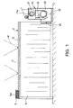
- FIG. 1 is a side view of a coating booth according to an
embodiment of the present invention.
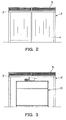
- FIG. 2 is a front view of the coating booth of this embodiment.
- FIG. 3 is a rear view of the coating booth of this embodiment.
- FIG. 4 is a plan view of the coating booth of this embodiment.
- FIG. 5 is a schematic view of a deodorization apparatus
according to this embodiment.
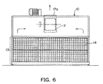
- FIG. 6 is a front view of the deodorization apparatus of this
embodiment.
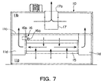
- FIG. 7 is a diagram showing the internal construction of the
deodorization apparatus of this embodiment.
- FIG. 8 is a flowchart illustrating control procedures executed
during operation of the deodorization apparatus.
- FIG. 9 is a side view of a coating booth according to this
embodiment which is equipped with a circulation duct for causing
exhaust gas to flow back into the booth main body from the
deodorization apparatus.
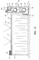
- FIG. 10 is a diagram showing amodification of the deodorization
apparatus of this embodiment.
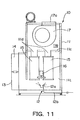
- FIG. 11 is a diagram showing a modi f ication of the deodorization
apparatus of this embodiment.
-
BEST MODE FOR CARRYING OUT THE INVENTION
-
In the following, a deodorization apparatus and a deodorization
method according to an embodiment of the present invention will
be described as applied to a coating booth. It should be noted that
what is described with reference to this embodiment is only given
by way of example, and that the following detailed specifications
of the deodorization apparatus and the deodorization method of the
present invention allow various modifications without departing
from the technical scope of the invention as defined by the claims
and are not restricted to the following description.
-
First, an outline of the coating booth of this embodiment will
be described with reference to FIG. 1.
-
A booth 1 of this embodiment includes as main components a
booth main body 2 restraining diffusion of malodor generated during
operation, and a deodorization unit 10 for deodorizing malodor
generated in the booth main body 2.
-
Further, in addition to these components, there are installed
in the coating booth 1 coating devices needed for coating operation
(e.g., an air compressor and a coating gun) (not shown).
-
The booth main body 2 is a so-called "indoor-installed type"
plain booth, and includes a ceiling frame 3 suspended by wires W
and a vinyl curtain 4 hanging down from the peripheral edge of the
ceiling frame 3. The interior of the booth main body 2 is separated
from the exterior by the curtain 4.
-
Further, as shown in Fig. 4, the ceiling frame 3 is equipped
with an intake duct 5 and a plurality of fluorescent lamps 6.
-
The intake duct 5 serves to introduce fresh air (atmospheric
air) into the booth main body 2 isolated from the atmospheric air.
The intake duct 5 is provided on the upper surface side of the ceiling
frame 3 and on the inlet side (the left-hand side in Fig. 1) of
the booth main body 2. Further, a dust collecting filter 5a is mounted
to the intake duct 5. The dust collecting filter 5a removes dust
from air before the air is introduced into the booth main body 2
as fresh air. As shown in FIG. 4, the fluorescent lamps 6 are mounted
to the lower surface of the ceiling frame 3.
-
Next, the deodorization apparatus 10 will be described.
-
As shown in FIGS. 5 through 7, the deodorization apparatus
10 includes a casing 11 constituting the contour of the deodorization
apparatus 10, a deodorant supply device 12 provided in the casing
11, an exhaust fan (airflow forming device) 13 forming an airflow
in the casing 11, various filters 14 and 15 catching malodorous
substance in the air flowing into the casing 11, and a main control
unit (not shown) performing concentrated control on the various
devices provided in the deodorization apparatus 10.
-
As shown in FIG. 5, the casing 11 can be divided into upper
and lower stages by a partition wall 11c installed at the middle
stage of the casing. In the following description, the casing forming
the space of the lower stage of the casing (below the partition
wall 11c) will be referred to as a first casing unit 11a. The casing
forming the space of the upper stage of the casing (above the partition
wall 11c) will be referred to as a second casing unit 11b.
-
First, the first casing unit 11a will be described.
-
As shown in FIGS. 5 and 6, on the front side of the first casing
unit 11a, there is formed the intake port 13. Further, the first
casing unit 11a is connected to the interior of the booth main body
2 through the intake port 13. Malodor in the booth main body 2 is
sucked into the first casing unit 11a through the intake port 13.
-
Further, the first filter 14 is mounted to the intake port
13.
-
The first filter 14 has a five-layer structure, and collects
relatively large malodorous substance (e.g., coating mist) due to
the physical properties of the filter base member thereof. Further,
the first filter 14 is detachable from the intake port 13, and allows
cleaning as needed.
-
Further, inside the first casing unit 11a, there are provided,
as components of the deodorant supply device 12, injection nozzles
12a for injecting deodorant into the first casing unit 11a. In order
to ensure uniform diffusion of the deodorant, six injection nozzles
12a in total are arranged at appropriate positions in the first
casing unit 11a.
-
Further, the deodorant supply device 12 is equipped with
injection amount adjusting devices (not shown) for adjusting the
injection amount (deodorant supply amount) to an appropriate amount.
-
In this embodiment, as the injection amount adjusting devices,
there are provided an electromagnetic valve adjusting the line
pressure (supply pressure) of a deodorant supply line 12b leading
to each of the injection nozzles 12a so as to change the injection
amount, a pressure sensor monitoring the line pressure of the
injection nozzle 12a, and a sub control unit (not shown) controlling
the electromagnetic valve according to the deodorant supply amount
calculated by the above-mentioned main control unit. In this
embodiment, the injection amount adjusting devices and the
above-mentioned main control unit constitute the supply amount
adjusting means and the supply amount calculating means according
to the claims of the invention.
-
In this embodiment, in calculating the deodorant supply amount
in the main control unit, the malodor amounts (malodor generation
amounts) at different times are calculated from the operating
condition of the coating apparatus, and the requisite amounts of
deodorant for deodorizing the malodor (malodor amount) as calculated
are calculated.
-
More specifically, the consumption amount of compressed air
consumed during coating operation (the pressure reduction amount
in the air tank), the malodorous substance generation amount (the
generation amount of coating mist or the like), and the requisite
supply amount of deodorant for deodorizing the malodorous substance
are related to each other through preliminary experiment, and the
compressed air consumption amount at a particular in time is read
first. Further, this compressed air consumption amount is converted
to a malodorous substance generation amount. Then, a desired
deodorant supply amount in correspondence with this generation
amount is calculated. Then, the electromagnetic valve is controlled
so as to attain an injection amount in conformity with the deodorant
supply amount calculated.
-
In this way, in this embodiment, the requisite amounts of
deodorant for deodorizing malodor at different times are supplied,
whereby surplus consumption of deodorant is restrained.
-
Next, the partition wall 11c will be described.
-
The partition wall 11c corresponds to the top plate of the
first casing unit 11a. Further, on either side of the partition
wall 11c, there is provided a ventilation duct 11d extending from
the inside of the first casing unit 11a to open in the upper end
surface of the partition wall 11c. Further, the second filter 15,
which is of a cylindrical configuration, is installed inside the
first casing unit 11a so as to be supported at both ends by the
lower ends of the ventilation ducts 11d.
-
Further, the interior of the second filter 15 communicates
with the above-mentioned ventilation ducts 11d. The air within the
first casing unit 11a is taken in from the outer peripheral portion
of the second filter 15, and reaches the ventilation ducts 11d by
way of the interior of the second filter 15. Then, it flows into
the space above the partition wall 11c from the ventilation ducts
11d.
-
In this embodiment, as the second filter 15, a chemical filter
is adopted which is superior in deodorant collecting/adsorbing
capacity. The malodorous substance in the first casing unit 11a
is collected by the second filter 15 together with the deodorant
as it passes through the second filter 15. The second filter 15
can be freely extracted from the inside of the first casing unit
11a, and can be replaced when soiled to a certain degree.
-
Regarding the replacement of the second filter 15, the
deodorization apparatus 10 of this embodiment is equipped with a
pressure difference sensor (not shown) for detecting a difference
in pressure between the upstream side and the downstream side of
the second filter 15. Based on the level of pressure difference
detected by the pressure difference sensor, the timing for
replacement of the second filter 15 is ascertained.
-
Further, in connection with the illustration of the second
filter 15, the deodorization apparatus 10 of this embodiment is
equipped with a rotation drive device 16 for rotating the second
filter 15.
-
The rotation drive device 16 includes a driving roller 16a
held in contact with the outer periphery of the second filter 15
and adapted to rotate the same, a drive motor 16b for rotating the
driving roller 16a, and a sub control unit for adjusting the RPM
of the drive motor 16b according to the RPM of the drive motor 16b
suitable for the collection amount of the malodorous substance and
the deodorant at a particular point in time calculated by the
above-mentioned main control unit.
-
Through rotation of the driving roller 16a, the second filter
15 is rotated, and a collecting surface with high collection
efficiency is successively moved in the inflow direction (toward
the airflow) of the gas containing the deodorant and the malodorous
substance. Further, in this embodiment, the rotation drive device
16 and the above-mentioned main control unit constitute the moving
device, moving amount changing means, and collection amount
calculating means of the present invention.
-
As in the calculation of the deodorant supply amount described
above, when calculating the collection amount of the malodorous
substance and deodorant by the main control unit, the amount of
compressed air consumed during coating is read first, and the
generation amount of the malodor is obtained from the consumption
amount of the compressed air. Then, regarding this generation amount
as the collection amount of the malodorous substance and deodorant,
the RPM of the drive motor 16b is set to a larger value as the collection
amount increases. Thus, the second filter 15 rotates at an
appropriate speed corresponding to the collection amount of the
malodorous substance and deodorant at a particular point in time,
so that local collection of the deodorant and malodorous substance
with respect to the second filter 15 is restrained.
-
In this way, in the rotation drive device 16, when the amount
of the deodorant and malodorous substance flowing into the second
filter 15 is large, the RPM of the second filter 15 is increased.
Further, a collecting surface with high collection efficiency (the
upper surface side of the second filter) is successively moved toward
the airflow side (which, in this embodiment, is mainly the lower
surface side of the second filter 15).
-
Further, the rotation of the second filter 15 is also
advantageous in enhancing the collection efficiency for the
deodorant and malodorous substance. This is due to the fact that
the deodorant and malodorous substance entering the filter base
member of the second filter 15 receive a centrifugal force as a
result of the rotation of the second filter 15, so that they remain
within the filter base member without reaching the internal space
of the second filter 15.
-
Next, the second casing unit 11b will be described.
-
As shown in FIG. 7, the second casing unit 11b is connected
to the first casing unit 11a below the partition wall 11c through
the above-mentioned ventilation ducts 11d. Further, the second
casing unit 11b is equipped with an exhaust fan 17 (blower) and
an exhaust port 17a open to the atmosphere. Moreover, by the airflow
formed by the exhaust fan 17, there is formed an airflow from the
first casing unit 11a to the second casing unit 11b.
-
That is, during the operation of the exhaust fan 17, the air
inside the booth main body 2 flows within the deodorization apparatus
10 in the following order: the booth main body 2, the intake port
13, the first casing unit 11a, the outer periphery of the second
filter 15, the interior of the second filter 15, the ventilation
ducts 11d, the second casing unit 11b, the exhaust fan 17, and the
exhaust port 17a.
-
Further, the exhaust fan 17 is provided with an air quantity
adjusting device (not shown). This air quantity adjusting device
adjusts the air quantity of the exhaust fan 17 based on a control
value calculated by the above-mentioned main control unit in order
to maintain the deodorization efficiency in the coating booth 1
at a fixed level. That is, when the malodor amount is large, the
deodorization efficiency is relatively low. Accordingly, so that
the air quantity of the exhaust fan 17 is set relatively high, with
the malodor amount being large or increasing in order to increase
the intake air amount, thereby restraining the deterioration in
the deodorization efficiency. Further, in this embodiment, the air
quantity adjusting device and the main control unit constitute the
air quantity adjusting means and malodor amount calculating means
according to the claims of the present invention.
-
As in the case of the above-described injection amount
adjusting device, in adjusting the air quantity, the malodor amount
in the booth main body 2 is calculated from the amount of compressed
air consumed at the time of injection of the coating material, and
based on the malodor amount thus calculated, the exhaust fan 17
is controlled so as to provide an output in conformity with the
malodor amount at a particular point in time.
-
FIG. 8 is a flowchart illustrating the procedures executed
in the main control unit during the operation of the deodorization
apparatus 10. In the following, various control procedures will
be illustrated with reference to this flowchart.
-
First, with the start of coating operation, the main control
unit reads the output of a pressure sensor provided in an air
compressor (S101). The pressure sensor serves to detect the pressure
in the air tank, that is, the amount of compressed air in the air
tank. In this step, the output value of this pressure sensor is
read each time a predetermined period of time elapses, monitoring
the pressure in the tank at different times during the coating
operation.
-
Subsequently, in the main control unit, the output change
amount, that is, the pressure change amount, at each point in time
from the output value read in step 101, and the consumption amount
of the compressed air is calculated through conversion from that
pressure change amount (S102).
-
Further, in the main control unit, after the processing of
step 102, in order to calculate the requisite control value for
the supply amount control in the injection amount adjusting device
12 (electromagnetic valve control), the air quantity control in
the air quantity adjusting device (the output control of the exhaust
fan 1), and the RPM control in the rotation drive device 16 (RPM
control of the drive motor 16b), the coating material injection
amount, that is, the generation amount of the malodorous substance
in the booth main body 2, is calculated based on the consumption
amount of the compressed air calculated in step 102 (S103).
-
Moreover, based on the malodor amount thus calculated, the
deodorant supply amount, the air quantity, and the filter rotating
speed are calculated (S104), and based on the calculated values,
the control values for the respective devices are obtained (S105).
The requisite collection amount of deodorant for the RPM control
of the second filter 15 is grasped from the deodorant supply amount
calculated in step 104. The control values are then transmitted
to the sub control unit provided in the injection amount adjusting
device 12, the air quantity adjusting device, and the sub control
unit provided in the rotation drive device 16,thereby controlling
the various devices through the sub control unit or directly (S106).
-
In this way, in the coating booth 1 of this embodiment, air
with malodor (the air in the booth main body 2) is first taken in
the first casing unit 11a through the first filter 14, collecting
relatively large coating mist by the first filter. Next, deodorant
is injected into that air to cause adhesion of the residual malodorous
substance, such as fine coating mist and vaporized solvent, to the
deodorant. After the residual malodorous substance is collected
by the second filter 15 together with the deodorant, the air is
discharged from the deodorization apparatus 10.
-
That is, the deodorization apparatus 10 effects both sufficient
deodorization with deodorant even in a small injection amount, and
collection by the filter, whereby it is possible to maintain the
deodorizing capacity by a simple maintenance operation involving
no water treatment, such as filter replacement or filter cleaning.
Further, through application of the deodorization apparatus 10,
there is no need to provide large-scale equipments, such as a vessel
and a contaminated water processing device.
-
The deodorization apparatus 10, in which deodorant is supplied
instead of water and which requires maintenance of the second filter
15, may seem to incur an increase in running cost. However, it
provides various advantages: (1) the deodorant, which has a higher
deodorizing capacity as compared with water, provides a sufficient
deodorizing effect with a small supply amount (injection amount) ;
(2) it requires no contaminated water processing by using a
contaminated water processing device; and (3) it requires no
periodical replacement of water. Thus, compared with the
conventional deodorization apparatus, it may be said that the
deodorization apparatus 10 can be maintained at a much lower running
cost.
-
It should be noted that the above-described embodiment is given
by way of example only, and the present invention allows specific
modifications as needed.
-
For example, while in the above-described apparatus the exhaust
port 17a is open to the atmosphere, and the deodorized air is
discharged into the atmosphere, it is also possible, as shown in
FIG. 9, to provide a circulation duct 50 establishing communication
from the exhaust port 17a to the above-mentioned intake duct 5,
thereby re-circulating the air in the deodorization apparatus 10
into the booth main body 2 through the circulation duct 50. In this
case, the adhesion of the deodorant and malodorous substance to
the second filter 15 is effected more reliably.
-
Further, while in the above-described embodiment the requisite
supply amount of the deodorant for deodorization of the malodor
and the malodor amount in the coating booth 1 are calculated from
the amount of compressed air consumed during injection of the coating
material, it is also possible to calculate them from the operating
amount of the coating gun (e.g., the needle stroke amount), the
coating time, and the like.
-
Further, while in the above-described deodorization apparatus
10 the air with the deodorant is purified by a single second filter
15, it is also possible, for example, to adopt a construction in
which a number of first casing units 11a each equipped with a second
filter 15 are superimposed one upon the other and connected to the
second filter 15 (see FIG. 10), that is, to install a plurality
of second filters 15. Further, this embodiment employs a casing
11 that can be separated by the partition wall 11c, so that, by
increasing the number of casings constituting the first casing unit
11a, the number of second filters 15 can be easily increased. That
is, the specifications of the deodorization apparatus 10 can be
easily changed according to the kind of operation, and the like
performed in each coating booth 1.
-
Further, as shown in FIG. 11, it is also possible to adopt
modifications such as mounting second filters 15 in a vertical
position and installing a plurality of them in the first casing
unit 11a. Further, while in the above-described embodiment the
collecting surface is moved by rotating the second filter 15 itself,
it is also possible to provide a current plate in the vicinity of
the second filter 15, changing the air inflow direction with respect
to the second filter 15 by means of this current plate. Further,
it is also possible to provide a cover covering the collecting surface
of the second filter 15 and to provide a slit serving as an air
intake port in a part of this cover, causing the collecting surface
to make relative movement by moving the cover itself.