EP1523592B1 - False twist texturing machine - Google Patents
False twist texturing machine Download PDFInfo
- Publication number
- EP1523592B1 EP1523592B1 EP03764930A EP03764930A EP1523592B1 EP 1523592 B1 EP1523592 B1 EP 1523592B1 EP 03764930 A EP03764930 A EP 03764930A EP 03764930 A EP03764930 A EP 03764930A EP 1523592 B1 EP1523592 B1 EP 1523592B1
- Authority
- EP
- European Patent Office
- Prior art keywords
- processing
- false twist
- frame
- module
- twist texturing
- Prior art date
- Legal status (The legal status is an assumption and is not a legal conclusion. Google has not performed a legal analysis and makes no representation as to the accuracy of the status listed.)
- Expired - Lifetime
Links
- 238000012545 processing Methods 0.000 claims description 195
- 238000001816 cooling Methods 0.000 claims description 13
- 238000004804 winding Methods 0.000 claims description 6
- 238000000034 method Methods 0.000 description 113
- 230000008569 process Effects 0.000 description 112
- 230000007246 mechanism Effects 0.000 description 32
- 238000003754 machining Methods 0.000 description 18
- 238000010438 heat treatment Methods 0.000 description 8
- 238000011282 treatment Methods 0.000 description 8
- 239000002131 composite material Substances 0.000 description 6
- 238000011161 development Methods 0.000 description 5
- 230000018109 developmental process Effects 0.000 description 5
- 238000004519 manufacturing process Methods 0.000 description 4
- 238000010276 construction Methods 0.000 description 3
- 238000013461 design Methods 0.000 description 3
- 230000000694 effects Effects 0.000 description 3
- 230000008901 benefit Effects 0.000 description 2
- 230000008859 change Effects 0.000 description 2
- 229920002334 Spandex Polymers 0.000 description 1
- 230000008878 coupling Effects 0.000 description 1
- 238000010168 coupling process Methods 0.000 description 1
- 238000005859 coupling reaction Methods 0.000 description 1
- 238000002788 crimping Methods 0.000 description 1
- 238000009826 distribution Methods 0.000 description 1
- 239000000835 fiber Substances 0.000 description 1
- 230000006872 improvement Effects 0.000 description 1
- 238000002203 pretreatment Methods 0.000 description 1
- 238000012546 transfer Methods 0.000 description 1
- 230000007704 transition Effects 0.000 description 1
Images


Classifications
-
- D—TEXTILES; PAPER
- D02—YARNS; MECHANICAL FINISHING OF YARNS OR ROPES; WARPING OR BEAMING
- D02G—CRIMPING OR CURLING FIBRES, FILAMENTS, THREADS, OR YARNS; YARNS OR THREADS
- D02G1/00—Producing crimped or curled fibres, filaments, yarns, or threads, giving them latent characteristics
- D02G1/02—Producing crimped or curled fibres, filaments, yarns, or threads, giving them latent characteristics by twisting, fixing the twist and backtwisting, i.e. by imparting false twist
- D02G1/0206—Producing crimped or curled fibres, filaments, yarns, or threads, giving them latent characteristics by twisting, fixing the twist and backtwisting, i.e. by imparting false twist by false-twisting
- D02G1/0266—Producing crimped or curled fibres, filaments, yarns, or threads, giving them latent characteristics by twisting, fixing the twist and backtwisting, i.e. by imparting false twist by false-twisting false-twisting machines
Definitions
- the invention relates to a false twist texturing machine for false twist texturing of a plurality of synthetic threads according to the preamble of claim 1.
- the false twist texturing machine has a plurality of processing points, wherein in each processing point at least one thread is treated by several processing units for finishing.
- the yarn is drawn in a false twist zone and textured and wound up after texturing into a coil.
- the process units such as delivery mechanisms, heaters, cooling devices and false twist texturing, are arranged for this purpose to a job structure on a machine frame, so that sets a predetermined yarn path in the processing stations.
- a false twist texturing machine is known, for example, from WO 01/92615.
- the plurality of processing stations are divided into several sections.
- 18 sections of 12 processing points can be formed.
- the processing sections are independently controllable.
- the processing sections are constructed such that in each processing point a job structure is realized in order to be able to optimally texture a yarn with a defined yarn path and predetermined yarn treatments.
- the invention is based on the proviso that a false twist texturing machine with a plurality of processing stations is used exclusively for the production of a specific yarn. On the contrary, the invention makes it possible for different types of yarn to be produced parallel to one another in a false twist texturing machine.
- the false twist texturing machine is designed with different peg structures in groups of processing sections.
- the job structures of the machining sections differ in the number and / or type of process units that are required for the guidance and treatment of one or more threads.
- job structure here is meant the arrangement of the process units within a processing section, which are required, for example, for stripping, texturing and stretching the threads associated with the processing section.
- an additional treatment of the threads could be achieved by including additional processing units in the job structure of the group of processing stations, such as additional heating devices.
- the processing units provided for the heat treatment could be formed at one of the processing sections by so-called contact heaters, in which the yarn is treated in contact with a heated surface.
- a heater could be used, in which the threads are heated without contact.
- high-temperature heater heaters the threads are passed over highly heated surfaces without contact.
- At least a part of the processing units is within the job structures of the processing sections Process modules held, which are removably attached to a module frame designed as a part of the machine frame. This makes it possible to modify the job structure of the processing section in a simple manner.
- the module frame can optionally be equipped with one or more process modules per processing section.
- the process modules carry at least one group of processing units, each of which carries out a process step in the processing stations of the processing section.
- the process modules each have an electrical distributor, which is connected to the process units of the process module and which has inputs and outputs for the electrical coupling of the process units.
- the drivable process units which are essentially formed by delivery mechanisms, are preferably driven by individual drives on the process modules, wherein the individual drives are supplied and controlled via the electrical distributor. All individual drives of the process units on the process module are controlled by a group converter. It is, however possible that each individual drive directly to the process module is assigned in each case one inverter.
- the module frame is arranged in the inlet area of the machine and the group of processing units carrying a thread from a supply spool is carried within the place structures of the processing sections.
- Such process units are formed by deduction delivery plants.
- the process modules are advantageously designed with additional receiving devices per processing point, by means of which optional additional processing units can be integrated within the processing point on the process module.
- additional processing units can optionally be provided per processing point.
- a second thread can be fed to the process module by the bobbin original in order to produce a composite thread in the processing station.
- a draw pin or a Tangel dressed a withdrawn from the deduction delivery thread could be additionally treated before the false twist texturing.
- an operating passage is formed between the module frame and a process frame.
- the process frame carries at least part of the processing units such as False twist text courier and delivery works.
- the process units can be operated from the operating gear on both sides, preferably by an operator.
- each processing section is preferably assigned a field control unit, by means of which all process parameters within the group can be defined and changed.
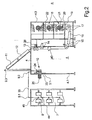
- Fig. 1 is a schematic plan view of an embodiment of the invention Falschdralltexturiermaschine is shown.
- the false twist texturing machine has a machine frame 4.
- the machine frame 4 is formed by a module frame 4.1, a process frame 4.2 and a Aufwickelgestell 4.3, which are firmly connected.
- a separate gate frame 7 is arranged at a distance to the module frame 4.1.
- a plurality of processing points 1.1, 1.2, 1.3, etc. are arranged parallel to each other in the longitudinal direction.
- processing points are preferably provided 218 processing points.
- the first three processing stations are identified by the reference symbols 1.1, 1.2 and 1.3.
- each of the processing stations 1 at least one thread is processed in each case.
- the plurality of processing stations 1 are divided into several processing sections 2. In the embodiment shown in FIG. 1, in each case 12 adjacent processing points 1.1, 1.2, 1.3, etc. form a processing section 2.
- FIG. 1 in each case 12 adjacent processing points 1.1, 1.2, 1.3, etc. form a processing section 2.
- machining sections 2.1 and 2.2 as well as partially the third machining section 2.3 shown
- Each machining section 2.1, 2.2, 2.3, etc. contain several processing units, which are held in a job structure in your machine frame 4, to deduct the threads of the processing section associated threads in parallel from original spools to texturize to stretch and wind up coils.
- Fig. 1 only a portion of the provided in the processing section or in the individual processing stations process units with the reference numerals 10, 11, 12, 13, 16 and 18 are shown schematically.
- the group of deduction delivery plants is marked, each processing point is assigned in each case a deduction delivery, to deduct a thread 38 from a supply spool 8.
- the supply spool 8 is received in the gate frame 7.
- the thread 38 is guided in a processing station, for example, the processing station 1.1 in a false twist zone, which is formed by the Primärloom owned 11, the cooling device 12 and the Falschdralltextkurieraggregat 13. Thereafter, the thread 38 is subjected to a post heat treatment in each of the processing points, which is carried out by the secondary heater 16.
- the thread 38 is wound to a bobbin 21 held on a bobbin holder 46 in the winder 18.
- the winders 18 occupy a width of 3 processing points. Therefore, each of three rewinders - will be discussed later - arranged in a column one above the other in the Aufwickelgestell 4.3.
- a field control unit 42 is assigned to each processing section.
- the field control units 42.1 and 42.2 as well as the field control units (not shown here) of the subsequent processing sections of the false twist texturing machine are coupled to a machine control 43.
- the process units of a processing section can thus be controlled and monitored independently of the processing units of the adjacent processing section.
- the processing sections 2 of the false twist texturing machine each have a specific job structure for processing the threads assigned to the processing section.
- the job structure of the machining section 2.1 will be described with reference to a cross-sectional view of a machining point of this machining section of FIG. 2 and the job structure of the machining section 2.2 with reference to the cross-sectional view of one of the machining points of this machining section of FIG.
- each processing point has a deduction delivery unit 10.
- the deduction delivery plants 10 of the processing section 2.1 are attached to a process module 3.1.
- the process module 3.1 is attached to the module frame 4.1. The design of the process module and the nature of the module frame 4.1 will be explained in more detail below.
- Each of the deduction suppliers is assigned to one of the original coil 8, which are arranged in the gate frame 7.
- each of the feed bobbins 8 is assigned a spare spool 44, wherein the thread end of the spool 8 is knotted to the thread spine of the reserve spool 44.
- the thread 38 is withdrawn via a head thread guide 45 and the thread guides 9.1 and 9.2 through the deduction delivery unit 10.
- the other process units are described in the job description below.
- the primary heater 11 In the thread running direction behind the deduction delivery unit 10 is the elongated primary heater 11, through which the thread 38 is running and is heated to a certain temperature.
- the primary heater 11 could be designed as a high-temperature heater, in which the Schuber vomtemperatur is above 300 ° C.
- the thread 38 in this case would preferably be heated without contact.
- the primary heater 11 is seated in this embodiment, two parallel tracks, so that the threads 38 two adjacent processing points are performed simultaneously by the primary heater 11.
- the cooling device 12 In the thread running direction behind the primary heater 11, the cooling device 12 is provided.
- the primary heater 11 and the cooling device 12 are arranged in this embodiment in a plane behind the other above the module frame 4.1 and the process frame 4.2, wherein between the module frame 4.1 and the process frame 4.2 an operating gear 5 is formed.
- a yarn guide 9.3 In the entrance area of the primary heater 11 is a yarn guide 9.3, which is preferably designed as a deflection roller, arranged so that the thread 38 is guided by the module frame 4.1 in a V-shaped yarn path to the process frame 4.2.
- the job structure could also be designed such that the primary heater 11 and the cooling device 12 are arranged in two roof-shaped mutually lying planes.
- the process frame 4.2 carries in the thread running direction in succession the Falschdralltextkurieraggregat 13, the drafting device 14, the swirling device 40 and the set-delivery 15.
- a false twist drive 26 an electric motor is preferably used, which is also attached to the process rack.
- the thread 38 passes through the swirling device 40.
- the thread 38 is guided into the secondary heating device 16 by the set delivery mechanism 15.
- the secondary heater 16 is for this purpose on the underside of the process frame 4.2 and the Aufwickelgestells 4.3, which are both joined together to form a frame part.
- the secondary heater 16 forms the thread transition from the process frame 4.2 to the winding frame 4.3. As a result, a very compact design is realized.
- the feed delivery plant 17 On the underside of the Aufwickelgestells 4.3 the feed delivery plant 17 is arranged, which immediately deducts the thread 38 from the secondary heater 16 and after deflecting the thread 38 leads to the winding device 18.
- the set delivery mechanism 15 and the feed delivery mechanism 17 are driven at a differential speed such that shrinkage treatment of the thread 38 within the secondary heater 16 is possible.
- the Secondary heater 16 could in this case be formed by a diphyl-heated contact heater.
- the winding device 18- is schematically characterized in this embodiment by a traverse 20, a drive roller 19, a coil holder 46 and a coil 21.
- the winding device 18 also includes a sleeve magazine 22 to perform an automatic bobbin change.
- the auxiliary equipment required for replacing the full bobbins are not shown here.
- a total of three take-up devices 18 of adjacent processing points are arranged one above the other in terms of floor space.
- the winders of the processing section form a machine longitudinal side, over the length of which a Doffgang 6 extends. From the Doffgang 6 let out the full bobbins transport.
- Each delivery mechanism is formed by a godet 23 and an overflow roller 24 associated with the godet 23.
- the godet 23 is driven by a single drive 25.
- the individual drive 25 is preferably formed by an electric motor.
- the overflow roller 24 is freely rotatably mounted, wherein the thread 38 is guided with several wraps on the godet 23 and the overflow roller 24.
- the illustrated in Fig. 2 job structure of the processing section 2.1 has in the processing stations on the process units to draw a submitted thread 38 in a basic process and to texture.
- the thread 38 is withdrawn by the deduction delivery unit 10 of the original spool 8, guided in the false twist zone.
- Falschdralltextkurieraggregat 13 at the end of the false twist zone a false twist is generated in the thread 38, which runs back to the primary heater 11.
- Within the primary heater 11 and the cooling device 12 is a fixing of the conditional by the texturing Crimping in the multifilament yarn 38.
- the yarn 38 is withdrawn from the false twist zone by the draw delivery unit 14 and drawn.
- the stretch delivery unit 14 is driven at a higher speed than the deduction delivery unit 10.
- the thread 38 is wound into a coil 21.
- an operating gear 5 is formed between the module frame 4.1 and the process frame 4.2.
- the process units on the module frame 4.1 and the process units on the process frame 4.2 can advantageously be operated by an operator from the operation gear 5.
- a Doffgang 6 is provided on the longitudinal side of the Aufwickelgestells 4.3.
- FIG. 3.1 a front view of the process module 3.1 and in FIG. 3.2 a rear view of the process module 3.1 are shown.
- FIG. 3.1 a front view of the process module 3.1 and in FIG. 3.2 a rear view of the process module 3.1 are shown.
- the process module 3.1 is mounted replaceably on the module frame 4.1 via a plurality of fastening elements 27.
- the module frame 4.1 in this case has several module slots 47. Overall, three module slots 47.1, 47.2 and 47.3 are formed on the module frame 4.1.
- the process module 3.1 is attached.
- the process module 3.1 of the processing section 2.1 carries the group of deduction delivery plants 10. In Fig. 3.1 and 3.2, three adjacent deduction delivery plants 10.1, 10.2 and 10.3 are shown. Each of the delivery units 10.1, 10.2 and 10.3 is driven by a single drive 25.1, 25.2 and 25.3. Thus drives the single drive 25.1 the deduction delivery 10.1 and the single drive 25.2 the deduction delivery 10.2.
- Each of the deduction delivery 10.1, 10.2, 10.3, etc. of the processing points pulls a thread 38 from a supply spool on the yarn guide 9.1.
- all individual drives 25 of the deduction delivery units 10 are connected to an electrical distributor 48.
- the electrical distributor 48 has a plurality of plug connections 49. Via the plug connections 49 and the electrical distributor 48, the electrical connection of the individual drives 25 of the delivery units 10 takes place.
- the individual drives 25 are preferably controlled via a group converter.
- the group converter could either be part of the electrical distributor 48 or be arranged externally in an electronic assembly assigned to the machining sections 2.1.
- the job structure of the adjacent machining section 2.2 of the embodiment is shown by a cross section of a machining point of the machining section 2.2 in FIG.
- the job structure of the processing station 2.2 is substantially identical to the job structure of the processing station 2.1, so that reference is made at this point to the previous description and then only the differences in job structure will be described. Because of the overview, the components of the same function have been identified with identical reference numerals.
- the process module 3.1 carries the deduction delivery units 10 of the processing points of the processing section 2.2.
- the construction of the process module 3.1 is identical to the process module arranged in the adjacent processing section 2.1. In that regard, reference is made to the preceding description.
- a delivery mechanism 29 and a delivery point 36 are arranged per processing point.
- a supply reel 37 is held in each processing station, on which an additional thread 39 is presented.
- the additional thread 39 is subtracted by the delivery mechanism 29 to the process module 3.2 and above the operating 5 arranged deflection rollers 41.1 and 41.2 supplied to the stretch delivery 14.
- the additional thread and the thread 38 are brought together to form a composite thread.
- the job structure of the processing section 2.2 thus contains additional processing units, - to produce in each case a composite thread in the associated processing points of the processing section 2.2.
- an additional thread z. B. an elastane thread the crimped thread are attached.
- the thread 38 is withdrawn in each of the processing points of the machining section 2.2 and fed to the false twist zone by the deduction mechanism 10.
- the additional thread 39 is withdrawn by the delivery mechanism 29 from the original spool 37 via a yarn guide 35 attached to the process module 3.2 in each of the processing points.
- the supply spool 37 is arranged at the initial position 36 on the process module 3.2.
- the additional thread 39 is passed over deflection rollers 41.1 and 41.2 at the false twist zone directly to the stretch delivery unit 14. After texturing and stretching of the thread 38 of the thread 38 and the additional thread 39 is connected in the swirling device 40.
- the resulting composite thread is wound up after a heat treatment in the secondary heater 16 to form a coil 21.
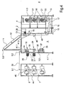
- the inlet area of the processing section 2.2 is shown schematically in different views for a more detailed explanation of the process modules 3.1 and 3.2 in Figures 5.1 and 5.2.
- Fig. 5.1 shows a detail in a front view of the operation gear 5 out
- Fig. 5.2 shows a section of the back of the module frame 4.1.
- the module frame 4.1 is occupied in the processing section 2.2 in the module slots 47.1 and 47.2, each with the process module 3.1 and 3.2.
- the process module 3.1 in the processing section 2.2 is identical to the process module 2.1 in the processing section 2.1. In that regard, reference is made to the preceding description.
- the process module 3.2 carries the group of delivery mechanisms 29 of the processing section 2.2.
- Fig. 5.1 the first three delivery mechanisms 29.1, 29.2, 29.3 of the groups are shown.
- Each of the delivery mechanisms 29 is formed by a driven godet 31 and an overrun roller 30.
- the godet 31 is driven by a single drive 33, wherein the individual drives 33.1, 33.2 and 33.3 of the first three delivery mechanisms 29.1, 29.3 and 29.3 are shown.
- the process module 3.2 also has an electrical distributor 48, which is coupled to the individual drives 33 of the delivery mechanisms 29.
- the electrical distributor 48 is connected via the plug connections 49 to an external power supply and control device.
- a feed point 36 which is provided for receiving a feed bobbin 37, is provided below the delivery mechanisms 29 for each processing point of the processing section 2.2.
- a thread guide 35 is arranged on the process module 3.2 per processing point.
- the following processing sections of the embodiment may each have a job structure corresponding to the job structure of the machining section 2.1 of FIG. 2 or the job structure of the machining section 2.2 of FIG.
- at least one of the processing stations of the embodiment has a third different job structure for producing a further yarn type.
- false twist texturing machines are operated with few different spot structures in the processing sections.
- the location structures of the processing sections are substantially changed by additional process units, which are arranged substantially in the inlet region of the machine.
- all processing units arranged within the job structure are suitable for generating changes in the job structure.
- the job structure of the processing section 2.1 of the embodiment could be changed by the fact that the secondary heater 16 is not operated, so that a false twist-textured thread is wound into a coil without a post-heat treatment.
- a primary heater 11 in a processing section which is designed as a non-contact heater and to use a contact keyer as a primary heater 11 in an adjacent processing section.
- the invention is not limited to the fact that the process module are arranged exclusively in a module frame placed in the inlet region.
- the process rack is suitable for accommodating one or more process modules with one or more groups of processing units as a module rack.
- a process module which is constructed correspondingly in the process module 3.1, could be arranged between the swirling device 40 and the draft delivery device 14. This would precede an additional delivery mechanism of the swirling device 40, so that a separate adjustment of the tension for swirling the thread or threads is possible.
- FIG. 6 shows further exemplary embodiments of process modules 3, such as could be used, for example, in one of the processing sections.
- the embodiment of the process module 3 shown in FIG. 3.1 is particularly suitable for producing a composite thread.
- the delivery unit 10 and the delivery mechanism 29 are mounted together on the process module 3.
- FIG. 6.1 shows the structure of the process module 3 of a processing station.
- the delivery mechanism 29 is at the process module 3, the reference point 36 and the Thread guide 35 assigned.
- a document spool 37 is held.
- the deduction delivery unit 10 and the delivery mechanism 29 on the process module 3 are preferably arranged in different thread running planes to guide two parallel threads without additional deflection in the processing site.
- FIG. 6.2 shows a further exemplary embodiment of a process module 3, in which the process module 3 has the trigger delivery unit and a further delivery mechanism 29. Both delivery mechanisms are each formed by an overflow roller and a godet. Between the delivery mechanisms 10 and 29, a swirling device 40 is held on the process module. The swirling device 40 is connected to a compressed air source (not shown here), so that the thread 38 routed through a thread channel is swirled by a stream of compressed air. This pre-treatment of the thread 38 preceding the false twist crimp leads to an improvement in the bulkiness of the thread in the crimped state.
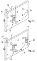
- FIG. 7 shows a further exemplary embodiment of a process module 3 schematically in a section for a processing station.
- the process module 3 is shown here in a first configuration in FIG. 7.1 and in a second configuration in FIG. 7.2.
- the deduction delivery unit 10 already described above is arranged.
- the deduction delivery 10 are associated with a plurality of receiving device 28, through which the inclusion of additional process units is possible.
- the process module 3 is described without additional processing units held in the receiving devices 28.
- the receiving devices of the process module 3 are occupied by an additional delivery mechanism 29 and a draw pin 34.
- a thread 38 from a document coil.
- the thread 38 is guided into a first draw zone, which extends between the deduction delivery unit 10 and the delivery mechanism 29.
- a heated draw pin 34 is arranged within the draw zone.
- the draw pin 34 could in this case be heated to a surface temperature in the range from 80.degree. C. to 160.degree.
- the draw pin 34 is looped by the thread 38 and withdrawn from the delivery mechanism 29.
- the draw pin 34 could be assigned to a thread guide on the process module 3, which would be variable in its position to set a certain angle of wrap on the draw pin 34. From the delivery mechanism 29, the thus pre-stretched thread 38 is guided into the false twist texturing zone.
- the further yarn path could correspond to the job structure of the processing section 2.1 of the embodiment described.
Landscapes
- Engineering & Computer Science (AREA)
- Mechanical Engineering (AREA)
- Textile Engineering (AREA)
- Yarns And Mechanical Finishing Of Yarns Or Ropes (AREA)
Description
Die Erfindung betrifft eine Falschdralltexturiermaschine zum Falschdralltexturieren mehrerer synthetischer Fäden gemäß dem Oberbegriff des Anspruchs 1.The invention relates to a false twist texturing machine for false twist texturing of a plurality of synthetic threads according to the preamble of
Es ist bekannt, dass derartige Falschdralltexturiermaschinen dazu verwendet werden, schmelzgesponnene multifile Fäden zu texturieren und somit den Fäden in ihrem Aufbau und Aussehen nach Möglichkeit den Naturfasern nachzubilden. Hierzu weist die Falschdralltexturiermaschine eine Vielzahl von Bearbeitungsstellen auf, wobei in jeder Bearbeitungsstelle zumindest ein Faden durch mehre Prozessaggregate zur Veredlung behandelt wird. Im wesentlichen wird dabei der Faden in einer Falschdrallzone verstreckt und texturiert und nach dem Texturieren zu einer Spule aufgewickelt. Die Prozessaggregate, wie beispielsweise Lieferwerke, Heizeinrichtungen, Kühleinrichtungen und Falschdralltexturieraggregate, sind hierzu zu einem Stellenaufbau an einem Maschinengestell angeordnet, so dass sich ein vorbestimmter Fadenlauf in den Bearbeitungsstellen einstellt. Eine derartige Falschdralltexturiermaschine ist beispielsweise aus der WO 01/92615 bekannt. Bei der bekannten Falschdralltexturiermaschine sind die Vielzahl von Bearbeitungsstellen in mehreren Sektionen aufgeteilt. So lassen sich beispielsweise bei Verwendung von einer Vielzahl von 216 Bearbeitungsstellen beispielsweise 18 Sektionen à 12 Bearbeitungsstellen bilden. Zur Erhöhung der Flexibilität sind bei der bekannten Falschdralltexturiermaschine die Bearbeitungssektionen unabhängig voneinander steuerbar. Dabei sind die Bearbeitungssektionen derart aufgebaut, dass in jeder Bearbeitungsstelle ein Stellenaufbau realisiert ist, um einen Faden mit definiertem Fadenlauf und vorbestimmten Fadenbehandlungen optimal texturieren zu können.It is known that such false twist texturing machines are used to texturize melt-spun multifilament yarns and thus to replicate, as far as possible, the natural fibers in their structure and appearance. For this purpose, the false twist texturing machine has a plurality of processing points, wherein in each processing point at least one thread is treated by several processing units for finishing. In essence, the yarn is drawn in a false twist zone and textured and wound up after texturing into a coil. The process units, such as delivery mechanisms, heaters, cooling devices and false twist texturing, are arranged for this purpose to a job structure on a machine frame, so that sets a predetermined yarn path in the processing stations. Such a false twist texturing machine is known, for example, from WO 01/92615. In the known false twist texturing machine, the plurality of processing stations are divided into several sections. Thus, for example, when using a plurality of 216 processing points, for example, 18 sections of 12 processing points can be formed. To increase the flexibility of the known Falschdralltexturiermaschine the processing sections are independently controllable. In this case, the processing sections are constructed such that in each processing point a job structure is realized in order to be able to optimally texture a yarn with a defined yarn path and predetermined yarn treatments.
Neue Entwicklungstendenzen in der Garnveredlung durch Falschdralltexturierung, wie beispielsweise aus der EP 11 03 641 A1 und der EP 11 01 848 A1 bekannt, zeigen ein verstärktes Interesse an sogenannten Effektgarnen, die durch ein Falschdralltexturierprozess herstellbar sind. Dieses erfordert zusätzliche Behandlungsschritte in dem Fadenlauf, die mit der bekannten Falschdralltexturiermaschine nicht ohne Probleme realisiert werden können. Die Herstellung von Effektgarnen war bisher den Lufttexturiermaschinen vorbehalten, wie beispielsweise aus der DE 36 23 370 A1 bekannt. Derartige Textariermaschinen besitzen wenige Bearbeitungsstellen mit einzeln angetriebenen und einstellbaren Prozessaggregaten, so dass die Bearbeitungsstellen individuell betrieben werden können. Eine derart hohe Flexibilität ist bei Falschdralltexturiermaschinen aufgrund der Vielzahl der Bearbeitungsstellen wirtschaftlich nicht ausführbar. Im Gegenteil beruhen die Falschdralltexturiermaschinen auf dem Konzept der Gruppenantriebe von Prozessaggregaten, um den Antriebs- und Steuerungsaufwand in Grenzen zu halten.New trends in yarn finishing by false twist texturing, such as
Demgemäss ist es Aufgabe der Erfindung, die gattungsgemäße Falschdralltexturiermaschine derart weiterzubilden, dass eine flexible Verwendung zur Herstellung von texturierten Garnen verschiedener Art und Ausführung möglich ist.Accordingly, it is an object of the invention to develop the generic Falschdralltexturiermaschine such that a flexible use for the production of textured yarns of various types and designs is possible.
Die erfindungsgemäße Aufgabe wird durch eine Falschdralltexturiermaschine mit den Merkmalen nach Anspruch 1 gelöst.The object of the invention is achieved by a false twist texturing machine having the features of
Vorteilhafte Weiterbildungen der Erfindung sind durch die Merkmale und Merkmalskombinationen der Unteransprüche definiert.Advantageous developments of the invention are defined by the features and feature combinations of the subclaims.
Die Erfindung löst sich von dem Vorbehalt, dass eine Falschdralltexturiermaschine mit einer Vielzahl von Bearbeitungsstellen ausschließlich zur Herstellung eines bestimmten Garnes eingesetzt ist Im Gegenteil geht die Erfindung den Weg, dass in einer Falschdralltexturiermaschine parallel nebeneinander unterschiedliche Garntypen hergestellt werden können.The invention is based on the proviso that a false twist texturing machine with a plurality of processing stations is used exclusively for the production of a specific yarn. On the contrary, the invention makes it possible for different types of yarn to be produced parallel to one another in a false twist texturing machine.
Hierzu ist die erfindungsgemäße Falschdralltexturiermaschine mit unterschiedlichen Stellenaufbauten in Gruppen von Bearbeitungssektionen ausgeführt. Die Stellenaufbauten der Bearbeitungssektionen unterscheiden sich dabei in Anzahl und / oder Art der Prozessaggregate, die zur Führung und Behandlung eines oder- mehrerer-Fäden benötigt werden. Als Stellenaufbau ist hierbei die Anordnung der Prozessaggregate innerhalb einer Bearbeitungssektion gemeint, die beispielsweise zum Abziehen, Texturieren und Verstrecken die der Bearbeitungssektion zugeordneten Fäden erforderlich sind. So könnte in einer der Bearbeitungssektionen eine zusätzlich Behandlung der Fäden dadurch erreicht werden, dass zusätzliche Prozessaggregate in dem Stellenaufbau der Gruppe der Bearbeitungsstellen wie beispielsweise zusätzliche Heizeinrichtungen aufgenommen sind. Unterschiedliche Behandlungen der den Bearbeitungssektionen zugeordneten Fäden lässt sich jedoch auch schon dadurch erreichen, dass die Anzahl der Prozessaggregate innerhalb des Stellenaufbaus gleich ist, jedoch die Art der Prozessaggregate zumindest einer Gruppe sich von der Art der Prozessaggregate einer anderen Gruppe unterscheidet. Als Beispiel könnten die zur Wärmebehandlung vorgesehenen Prozessaggregate bei einer der Bearbeitungssektionen durch sog. Kontaktheizer gebildet sein, bei welchem der Faden in Kontakt mit einer erwärmten Oberfläche behandelt wird. Bei einer benachbarten Bearbeitungssektion könnte dagegen eine Heizeinrichtung eingesetzt sein, bei welcher die Fäden ohne Kontakt erwärmt werden. Bei diesen als sogenannten Hochtemperaturheizer bekannten Heizeinrichtungen werden die Fäden über hocherhitzte Oberflächen ohne Kontakt geführt. Die Erfindung besitzt somit den besonderen Vorteil, dass die Vielzahl der in Gruppen eingeteilten Bearbeitungsstellen flexibel zur Bearbeitung von Fäden eingesetzt werden können. Es lassen sich somit vorteilhaft gleichzeitig verschiedene Garne mit einer Maschine herstellen.For this purpose, the false twist texturing machine according to the invention is designed with different peg structures in groups of processing sections. The job structures of the machining sections differ in the number and / or type of process units that are required for the guidance and treatment of one or more threads. As job structure here is meant the arrangement of the process units within a processing section, which are required, for example, for stripping, texturing and stretching the threads associated with the processing section. Thus, in one of the processing sections, an additional treatment of the threads could be achieved by including additional processing units in the job structure of the group of processing stations, such as additional heating devices. However, different treatments of the threads assigned to the machining sections can also be achieved in that the number of process units within the job structure is the same, but the type of process units of at least one group differs from the type of process units of another group. As an example, the processing units provided for the heat treatment could be formed at one of the processing sections by so-called contact heaters, in which the yarn is treated in contact with a heated surface. In contrast, in a neighboring processing section, a heater could be used, in which the threads are heated without contact. In these known as so-called high-temperature heater heaters, the threads are passed over highly heated surfaces without contact. The invention thus has the particular advantage that the plurality of processing stations divided into groups can be used flexibly for processing threads. It can thus be advantageous simultaneously produce different yarns with a machine.
Um die Flexibilität der Verwendung der erfindungsgemäßen Falschdralltexturiermaschine noch zu verbessern, ist zumindest ein Teil der Prozessaggregate innerhalb der Stellenaufbauten der Bearbeitungssektionen durch Prozessmodule gehalten, die auswechselbar an einem als Modulgestell ausgebildeten Teil des Maschinengestells befestigt sind. Damit ist die Möglichkeit gegeben, den Stellenaufbau der Bearbeitungssektion auf einfache Weise zu modifizieren.In order to further improve the flexibility of using the false twist texturing machine according to the invention, at least a part of the processing units is within the job structures of the processing sections Process modules held, which are removably attached to a module frame designed as a part of the machine frame. This makes it possible to modify the job structure of the processing section in a simple manner.
Hierbei ist besonders vorteilhaft, wenn das Modulgestell gemäß einer vorteilhaften Weiterbildung der erfindungsgemäßen Falschdralltexturiermaschine wahlweise pro Bearbeitungssektion mit einem oder mehreren Prozessmodulen bestückbar ist. Die Prozessmodule tragen zumindest eine Gruppe von Prozessaggregaten, die in den Bearbeitungsstellen der Bearbeitungssektion jeweils einen Prozessschritt ausführen. So lässt sich durch Wahl und Zusammenstellung mehrere Prozessmodule vorteilhaft Garntypen herstellen, die aus mehreren Fäden gebildet sind. Somit ist ein flexibler Stellenaufbau gegeben, um zusätzliche Prozessaggregate zu integrieren, die gegenüber einem Standardprozess benötigt werden, um spezielle Effektgarne herzustellen.In this case, it is particularly advantageous if, according to an advantageous development of the false twist texturing machine according to the invention, the module frame can optionally be equipped with one or more process modules per processing section. The process modules carry at least one group of processing units, each of which carries out a process step in the processing stations of the processing section. Thus, by selecting and assembling several process modules, it is advantageously possible to produce yarn types which are formed from a plurality of threads. Thus, a flexible job set-up is provided to integrate additional process aggregates needed over a standard process to produce special effect yarns.
Gemäß einer besonders vorteilhaften Weiterbildung der Erfindung weisen die Prozessmodule jeweils einen Elektrikverteiler auf, welcher mit den Prozessaggregaten des Prozessmoduls verbunden ist und welcher Eingänge und Ausgänge zur elektrischen Ankopplung der Prozessaggregate aufweist. Damit wird einerseits der Verkabelungsaufwand zur Versorgung einzelner Prozessaggregate innerhalb der Bearbeitungssektion erheblich vermindert und andererseits das Auswechseln einzelner Prozessmodule durch einfaches Lösen von Steckverbindungen zwischen Versorgungsleitungen und dem Elektrikverteiler erheblich vereinfacht.According to a particularly advantageous embodiment of the invention, the process modules each have an electrical distributor, which is connected to the process units of the process module and which has inputs and outputs for the electrical coupling of the process units. Thus, on the one hand, the cabling effort to supply individual process units within the processing section is significantly reduced and on the other hand greatly simplifies the replacement of individual process modules by simply loosening plug connections between supply lines and the electrical distributor.
Die antreibbaren Prozessaggregate, die im wesentlichen durch Lieferwerke gebildet sind, werden an den Prozessmodulen bevorzugt durch Einzelantriebe angetrieben, wobei die Einzelantriebe über den Elektrikverteiler versorgt und angesteuert werden. Hierbei werden alle Einzelantriebe der Prozessaggregate an dem Prozessmodul durch einen Gruppenumrichter gesteuert. Es ist jedoch auch möglich, dass jedem Einzelantrieb unmittelbar an dem Prozessmodul jeweils ein Umrichter zugeordnet ist.The drivable process units, which are essentially formed by delivery mechanisms, are preferably driven by individual drives on the process modules, wherein the individual drives are supplied and controlled via the electrical distributor. All individual drives of the process units on the process module are controlled by a group converter. It is, however possible that each individual drive directly to the process module is assigned in each case one inverter.
Es hat sich gezeigt, dass die unterschiedlichen Behandlungen zur Herstellung verschiedener Garntypen im wesentlichen im Einlaufbereich des Prozesses erfolgen. Aus dieser Erkenntnis heraus, ist gemäß einer vorteilhaften Weiterbildung der erfindungsgemäßen Falschdralltexturiermaschine das Modulgestell in dem Einlaufbereich der Maschine angeordnet und innerhalb der Stellenaufbauten der Bearbeitungssektionen die Gruppe der Prozessaggregate trägt, die einen Faden von einer Vorlagespule abzieht. Derartige Prozessaggregate werden durch Abzugslieferwerke gebildet.It has been found that the different treatments for the production of different types of yarn take place essentially in the inlet area of the process. On the basis of this finding, according to an advantageous further development of the false twist texturing machine according to the invention, the module frame is arranged in the inlet area of the machine and the group of processing units carrying a thread from a supply spool is carried within the place structures of the processing sections. Such process units are formed by deduction delivery plants.
Zur weiteren Erhöhung der Flexibilität insbesondere im Einlaufbereich der Maschine sind die Prozessmodule vorteilhaft mit zusätzlichen Aufnahmeeinrichtungen pro Bearbeitungsstelle ausgeführt, durch welche wahlweise zusätzliche Prozessaggregate innerhalb der Bearbeitungsstelle an dem Prozessmodul integrierbar sind.To further increase the flexibility, in particular in the inlet region of the machine, the process modules are advantageously designed with additional receiving devices per processing point, by means of which optional additional processing units can be integrated within the processing point on the process module.
Als zusätzliche Prozessaggregate können hierbei wahlweise pro Bearbeitungsstelle weitere Lieferwerke, Streckstifte, Tangeleinrichtungen und /oder Spulenvorlage vorgesehen sein. So lässt sich beispielsweise durch die Spulenvorlage ein zweiter Faden an dem Prozessmodul dem Prozess zuführen, um in der Bearbeitungsstelle ein Verbundfaden herzustellen. Durch einen Streckstift oder einer Tangeleinrichtung könnte ein von dem Abzugslieferwerk abgezogener Faden vor dem Falschdralltexturieren zusätzlich behandelt werden.As additional processing units, additional delivery units, drafting pins, Tangeleinrichtungen and / or bobbin original can optionally be provided per processing point. For example, a second thread can be fed to the process module by the bobbin original in order to produce a composite thread in the processing station. By a draw pin or a Tangeleinrichtung a withdrawn from the deduction delivery thread could be additionally treated before the false twist texturing.
Um die Bedienbarkeit der Prozessaggregate innerhalb der Falschdralltexturiermaschine auf einfache Weise zu ermöglichen, ist gemäß einer vorteilhaften Weiterbildung der Erfindung ein Bediengang zwischen dem Modulgestell und einem Prozessgestell gebildet. Dabei trägt das Prozessgestell zumindest einen Teil der Prozessaggregate wie beispielsweise Falschdralltextkurieraggregat und Lieferwerke. Die Prozessaggregate lassen sich aus dem Bediengang zu beiden Seiten hin vorzugsweise durch eine Bedienperson bedienen.In order to enable the operability of the process units within the false twist texturing machine in a simple manner, according to an advantageous development of the invention, an operating passage is formed between the module frame and a process frame. The process frame carries at least part of the processing units such as False twist text courier and delivery works. The process units can be operated from the operating gear on both sides, preferably by an operator.
Durch die Weiterbildungen der Erfindung nach Anspruch 9 und Anspruch 10 ist gewährleistet, dass die in der Falschdralltexturiermaschine geführten Fäden sich nicht kreuzen. Durch den wenig umgelenkten Fadenlauf innerhalb einer Bearbeitungsstelle lässt sich unabhängig vom Garntyp der Faden in einem sehr stabilen und kurzen Fadenlauf führen. Die Anordnung der Heizeinrichtung und der Kühleinrichtung oberhalb des Bedienganges hat zudem den Vorteil, dass eine ausreichende Länge zur Wärmebehandlung und Abkühlung des Falschdrallfadens realisierbar ist. Durch die zu einem Gestellteil zusammengefügten Prozess und Aufwickelgestelle wird zudem ein kompakter Aufbau der Falschdralltexturiermaschine erreicht.Due to the developments of the invention according to claim 9 and
Um die Einstellung der Prozessparameter wie beispielsweise Abzugsgeschwindigkeiten, Verstreckverhältnisse oder Heizereinstellungen auf einfache Art und Weise zu verändern, sind die den Stellenaufbau einer der Bearbeitungssektionen bildenden Prozessaggregate unabhängig von den Prozessaggregaten der benachbarten Bearbeitungssektion gesteuert und überwacht. Hierzu ist vorzugsweise jeder Bearbeitungssektion eine Feldsteuereinheit zugeordnet, durch welche sämtliche Prozessparameter innerhalb der Gruppe festgelegt und veränderbar sind.In order to change the setting of the process parameters such as take-off speeds, drawing ratios or heater settings in a simple manner, the processing units forming the job structure of one of the processing sections are controlled and monitored independently of the processing units of the adjacent processing section. For this purpose, each processing section is preferably assigned a field control unit, by means of which all process parameters within the group can be defined and changed.
Die Erfindung wird anhand eines Ausführungsbeispiels unter Bezug auf die beigefügten Zeichnungen nachfolgend näher beschrieben.The invention will be described in more detail below with reference to an embodiment with reference to the accompanying drawings.
Es stellen dar.
- Fig.
- 1 schematisch eine Draufsicht eines Ausführungsbeispiels der erfindungsgemäßen Falschdralltexturiermaschine
- Fig. 2
- schematisch einen Querschnitt der Bearbeitungsstelle einer Bearbeitungssektion des Ausführungsbeispiels nach Fig. 1
- Fig. 3
- schematisch Ansichten des Prozessmoduls der Bearbeitungssektion gemäß Fig. 2
- Fig. 4
- schematisch ein- Querschnitt der Bearbeitungsstelle einer anderen Bearbeitungssektion des Ausführungsbeispiels nach Fig. 1
- Fig. 5
- schematische Ansichten der Prozessmodule der Bearbeitungssektion gemäß Fig. 4
- Fig. 6
- schematische Ansichten weiterer Ausführungsbeispiele von Prozessmodulen
- Fig. 7
- schematische Ansichten weiterer Ausführungsbeispiele von Prozessmodulen
- FIG.
- 1 shows schematically a plan view of an exemplary embodiment of the false twist texturing machine according to the invention
- Fig. 2
- schematically a cross section of the processing point of a processing section of the embodiment of FIG. 1
- Fig. 3
- schematic views of the process module of the processing section of FIG. 2
- Fig. 4
- schematically a cross-section of the processing point of another processing section of the embodiment of FIG. 1
- Fig. 5
- schematic views of the process modules of the processing section of FIG. 4
- Fig. 6
- schematic views of other embodiments of process modules
- Fig. 7
- schematic views of other embodiments of process modules
In Fig. 1 ist schematisch eine Draufsicht eines Ausführungsbeispiels der erfindungsgemäßen Falschdralltexturiermaschine dargestellt. Die Falschdralltexturiermaschine weist ein Maschinengestell 4 auf. Das Maschinengestell 4 wird dabei durch ein Modulgestell 4.1, einem Prozessgestell 4.2 und einem Aufwickelgestell 4.3 gebildet, die fest miteinander verbunden sind. Im Abstand zu dem Modulgestell 4.1 ist ein separates Gattergestell 7 angeordnet.In Fig. 1 is a schematic plan view of an embodiment of the invention Falschdralltexturiermaschine is shown. The false twist texturing machine has a
In dem Maschinengestell 4 sind in Längsrichtung eine Vielzahl von Bearbeitungsstellen 1.1, 1.2, 1.3 usw. parallel nebeneinander angeordnet. Üblicherweise sind in einer Falschdralltexturiermaschine über 200 Bearbeitungsstellen vorzugsweise 218 Bearbeitungsstellen vorgesehen. In dem Ausführungsbeispiel in Fig. 1 sind beispielhaft nur die ersten drei Bearbeitungsstellen mit den Bezugszeichen 1.1, 1.2 und 1.3 gekennzeichnet. In jeder der Bearbeitungsstellen 1 wird jeweils zumindest ein Faden bearbeitet. Die Vielzahl der Bearbeitungsstellen 1 sind in mehreren Bearbeitungssektionen 2 aufgeteilt. Bei dem in Fig. 1 gezeigten Ausführungsbeispiel bilden jeweils 12 nebeneinander liegende Bearbeitungsstellen 1.1, 1.2, 1.3 usw. eine Bearbeitungssektion 2. In Fig. 1 sind hierzu beispielhaft die ersten beiden Bearbeitungssektionen 2.1 und 2.2 sowie teilweise die dritte Bearbeitungssektion 2.3 dargestellt Jede Bearbeitungssektion 2.1, 2.2, 2.3 usw. enthalten mehrere Prozessaggregate, die zu einem Stellenaufbau in dein Maschinengestell 4 gehalten sind, um die den Bearbeitungsstellen der Bearbeitungssektion zugeordneten Fäden parallel von Vorlagenspulen abzuziehen, zu texturieren, zu verstrecken und zu Spulen aufzuwickeln.In the
In Fig. 1 sind nur ein Teil der in der Bearbeitungssektion bzw. in den einzelnen Bearbeitungsstellen vorgesehenen Prozessaggregaten mit den Bezugszeichen 10, 11, 12, 13, 16 und 18 schematisch dargestellt. Durch das Bezugszeichen 10 ist die Gruppe der Abzugslieferwerke gekennzeichnet, wobei jeder Bearbeitungsstelle jeweils ein Abzugslieferwerk zugeordnet ist, um einen Faden 38 von einer Vorlagespule 8 abzuziehen. Die Vorlagespule 8 ist in dem Gattergestell 7 aufgenommen. Zum Verstrecken und Texturieren wird der Faden 38 in einer Bearbeitungsstelle beispielsweise der Bearbeitungsstelle 1.1 in eine Falschdrallzone geführt, die durch die Primärheizeinrichtung 11, die Kühleinrichtung 12 und das Falschdralltextkurieraggregat 13 gebildet ist. Im Anschluss daran wird der Faden 38 in jeder der Bearbeitungsstellen einer Wärmenachbehandlung unterzogen, die durch die Sekundärheizeinrichtung 16 erfolgt. Am Ende der Bearbeitung wird der Faden 38 zu einer an einem Spulenhalter 46 gehaltenen Spule 21 in der Aufwickeleinrichtung 18 gewickelt. Die Aufwickeleinrichtungen 18 nehmen eine Breite von 3 Bearbeitungsstellen ein. Daher sind jeweils drei Aufwickeleinrichtungen - hierauf wird später eingegangen - in einer Säule übereinander in dem Aufwickelgestell 4.3 angeordnet.In Fig. 1, only a portion of the provided in the processing section or in the individual processing stations process units with the
Zur Steuerung der Prozessaggregate, die in Fig. 1 nur teilweise durch die Bezugszeichen 10, 11, 13, 16 und 18 dargestellt sind, ist jeder Bearbeitungssektion eine Feldsteuereinheit 42 zugeordnet. So ist der Bearbeitungssektion 2.1 die Feldsteuereinheit 42.1 und der Bearbeitungssektion 2.2 die Feldsteuereinheit 42.2 zugeordnet. Die Feldsteuereinheiten 42.1 und 42.2 sowie die hier nicht weiter dargestellten Feldsteuereinheiten der nachfolgenden Bearbeitungssektionen der Falschdralltextiariermaschine sind mit einer Maschinensteuerung 43 gekoppelt. Die Prozessaggregate einer Bearbeitungssektion lassen sich somit unabhängig von den Prozessaggregaten der benachbarten Bearbeitungssektion steuern und überwachen.To control the process units, which are only partially represented in FIG. 1 by
Die Bearbeitungssektionen 2 der Falschdralltexturiermaschine besitzen jeweils einen bestimmten Stellenaufbau, um die der Bearbeitungssektion zugeordneten Fäden zu bearbeiten. Nachfolgend wird der Stellenaufbau der Bearbeitungssektion 2.1 anhand einer Querschnittsansicht einer Bearbeitungsstelle dieser Bearbeitungssektion gemäß Fig. 2 und der Stellenaufbau der Bearbeitungssektion 2.2 anhand der Querschnittsansicht einer der Bearbeitungsstellen dieser Bearbeitungssektion gemäß Fig. 4 beschrieben.The
In Fig. 2 ist eine Bearbeitungsstelle 1 der Bearbeitungssektion 2.1 schematisch in einer Querschnittsansicht dargestellt. Die in dem Maschinengestell 4 zu einem Stellenaufbau angeordneten Prozessaggregate werden in der Bearbeitungssektion 2.1 durch ein Abzugslieferwerk 10, eine Primärheizeinrichtung 11, eine Kühleinrichtung 12, ein Falschdralltextkurieraggregat 13, ein Strecklieferwerk 14, eine Verwirbelungseinrichtung 40, ein Set-Lieferwerk 15, eine Sekundärheizeinrichtung 16, ein Zufuhrlieferwerk 17 und eine Aufwickeleinrichtung 18 gebildet, wobei die Prozessaggregate zu einem Fadenlauf hintereinander angeordnet sind.2, a
In der Bearbeitungssektion 2.1 weist jede Bearbeitungsstelle ein Abzugslieferwerk 10 auf. Die Abzugslieferwerke 10 der Bearbeitungssektion 2.1 sind an einem Prozessmodul 3.1 angebracht. Das Prozessmodul 3.1 ist an dem Modulgestell 4.1 befestigt. Die Ausbildung des Prozessmoduls sowie Beschaffenheit des Modulgestells 4.1 werden nachfolgend noch näher erläutert.In the processing section 2.1, each processing point has a
Jedem der Abzugslieferwerke ist eine der Vorlagenspule 8 zugeordnet, die in dem Gattergestell 7 angeordnet sind. In dem Gattergestell 7 ist jeder den Vorlagespulen 8 jeweils eine Reservespule 44 zugeordnet, wobei das Fadenende der Vorlagenspule 8 mit dem Fadenanfang der Reservespule 44 verknotet ist. Von der Vorlagenspule 8 wird der Faden 38 über einen Kopffadenführer 45 und den Fadenführern 9.1 und 9.2 durch das Abzugslieferwerk 10 abgezogen.Each of the deduction suppliers is assigned to one of the
Anhand des Fadenlaufs des Fadens 38 in der Bearbeitungsstelle der Bearbeitungssektion 2.1 werden nachfolgend die weiteren Prozessaggregate im Stellenaufbau beschrieben. In Fadenlaufrichtung hinter dem Abzugslieferwerk 10 befindet sich die langgestreckte Primärheizeinrichtung 11, durch welche der Faden 38 läuft und auf eine bestimmte Temperatur erwärmt wird. Die Primärheizeinrichtung 11 könnte dabei als Hochtemperaturheizer ausgeführt sein, bei dem die Heizoberflächentemperatur über 300 °C liegt. Der Faden 38 würde in diesem Fall vorzugsweise ohne Kontakt erwärmt. Die Primärheizeinrichtung 11 sitzt an diesem Ausführungsbeispiel zwei parallele Laufspuren, so dass die Fäden 38 zwei nebeneinander liegende Bearbeitungsstellen gleichzeitig durch die Primärheizeinrichtung 11 geführt werden.Based on the yarn path of the
In Fadenlaufrichtung hinter der Primärheizeinrichtung 11 ist die Kühleinrichtung 12 vorgesehen. Die Primärheizeinrichtung 11 und die Kühleinrichtung 12 sind in diesem Ausführungsbeispiel in einer Ebene hintereinander oberhalb des Modulgestells 4.1 und des Prozessgestell 4.2 angeordnet, wobei zwischen dem Modulgestell 4.1 und dem Prozessgestell 4.2 ein Bediengang 5 ausgebildet ist. Im Eingangsbereich der Primärheizeinrichtung 11 ist ein Fadenführer 9.3, der vorzugsweise als eine Umlenkrolle ausgebildet ist, angeordnet, so dass der Faden 38 von dem Modulgestell 4.1 in einem V-förmigen Fadenlauf zum Prozessgestell 4.2 geführt wird. Der Stellenaufbau könne jedoch auch derart ausgebildet sein, dass die Primärheizeinrichtung 11 und die Kühleinrichtung 12 in zwei dachförmig zueinander liegenden Ebenen angeordnet sind.In the thread running direction behind the
Auf der zum Modulgestell 4.1 gegenüberliegenden Seite wird das Prozessgestell 4.2 angeordnet. Das Prozessgestell 4.2 trägt in Fadenlaufrichtung hintereinander das Falschdralltextkurieraggregat 13, das Strecklieferwerk 14, die Verwirbelungseinrichtung 40 und das Set-Lieferwerk 15. Dabei wird der Faden 38 vom Ausgang- -der Kühleinrichtung 12, die vorzugsweise durch eine Kühlschiene gebildet wird, zu dem Falschdralltextkurieraggregat 13 geführt. Das Falschdrallaggregat 13, das beispielsweise durch mehrere sich überlappende Friktionsscheiben gebildet sein kann, wird durch einen Falschdrallantrieb 26 angetrieben. Als Falschdrallantrieb 26 wird vorzugsweise ein Elektromotor verwendet, der ebenfalls an dem Prozessgestell angebracht ist.On the module frame 4.1 opposite side of the process frame 4.2 is arranged. The process frame 4.2 carries in the thread running direction in succession the
Durch das Strecklieferwerk 14 wird der Faden 38 aus der Falschdrallzone abgezogen, die sich zwischen dem Falschdralltextkurieraggregat 13 und dem Abzugslieferwerk 10 bildet. Das Strecklieferwerk 14 und das Abzugslieferwerk 10 werden zum Verstrecken des Fadens 38 in der Falschdrallzone mit einer Differenzgeschwindigkeit angetrieben.By the
Unterhalb des Strecklieferwerkes 14 durchläuft der Faden 38 die Verwirbelungseinrichtung 40. Durch das Set-Lieferwerk 15 wird der Faden 38 in die Sekundärheizeinrichtung 16 geführt. Die Sekundärheizeinrichtung 16 ist hierzu an der Unterseite des Prozessgestells 4.2 und des Aufwickelgestells 4.3, die beide zu einem Gestellteil zusammengefügt sind, angeordnet. Die Sekundärheizeinrichtung 16 bildet den Fadenübergang von dem Prozessgestell 4.2 zum Aufwickelgestell 4.3. Dadurch wird ein sehr kompakte Bauweise realisiert.Below the
Auf der Unterseite des Aufwickelgestells 4.3 ist das Zufuhrlieferwerk 17 angeordnet, welches unmittelbar den Faden 38 aus der Sekundärheizeinrichtung 16 abzieht und nach Umlenken den Faden 38 zu der Aufwickeleinrichtung 18 führt. Das Set-Lieferwerk 15 und das Zufuhrlieferwerk 17 werden mit einer Differenzgeschwindigkeit angetrieben, dass eine Schrumpfbehandlung des Fadens 38 innerhalb der Sekundärheizeinrichtung 16 möglich ist. Die Sekundärheizeinrichtung 16 könnte hierbei durch einen diphylbeheizten Kontaktheizer gebildet sein.On the underside of the Aufwickelgestells 4.3 the
Die Aufwickeleinrichtung 18- ist bei diesem Ausführungsbeispiel schematisch durch-eine Changierung 20, eine Treibwalze 19, einen Spulenhalter 46 und eine Spule 21 gekennzeichnet. Die Aufwickeleinrichtung 18 enthält zudem ein Hülsenmagazin 22, um einen automatischen Spulenwechsel auszuführen. Die zum Auswechseln der Vollspulen erforderlichen Hilfseinrichtung sind hierbei nicht näher dargestellt. In dem Aufwickelgestell 4.3 sind insgesamt drei Aufwickeleinrichtungen 18 benachbarter Bearbeitungsstellen etagenmäßig übereinander angeordnet. Die Aufwickeleinrichtungen der Bearbeitungssektion bilden eine Maschinenlängsseite, über deren Länge sich ein Doffgang 6 erstreckt. Aus dem Doffgang 6 heraus lassen-sich die Vollspulen abtransportieren.The winding device 18- is schematically characterized in this embodiment by a
Die Lieferwerke 10, 14, 15 und 17 in dem Stellenaufbau der Bearbeitungssektion 2.1 sind in ihrem Aufbau identisch, so dass am Beispiel des Abzugslieferwerkes 10 dieser nachfolgend erläutert wird. Jedes Lieferwerk wird durch eine Galette 23 und eine der Galette 23 zugeordnet Überlaufrolle 24 gebildet. Die Galette 23 wird über einen Einzelantrieb 25 angetrieben. Der Einzelantrieb 25 wird vorzugsweise durch einen Elektromotor gebildet. Die Überlaufrolle 24 ist frei drehbar gelagert, wobei der Faden 38 mit mehreren Umschlingungen über die Galette 23 und die Überlaufrolle 24 geführt wird.The
Der in Fig. 2 dargestellte Stellenaufbau der Bearbeitungssektion 2.1 weist in den Bearbeitungsstellen die Prozessaggregate auf, um einen vorgelegten Faden 38 in einem Grundverfahren zu verstrecken und zu texturieren. Hierzu wird der Faden 38 durch das Abzugslieferwerk 10 von der Vorlagenspule 8 abgezogen, in die Falschdrallzone geführt. Durch das Falschdralltextkurieraggregat 13 am Ende der Falschdrallzone wird in dem Faden 38 ein Falschdrall erzeugt, welcher bis zur Primärheizeinrichtung 11 zurückläuft. Innerhalb der Primärheizeinrichtung 11 und der Kühleinrichtung 12 erfolgt eine Fixierung der durch die Texturierung bedingte Kräuselung in den multifilen Faden 38. Der Faden 38 wird durch das Strecklieferwerk 14 aus der Falschdrallzone abgezogen und verstreckt. Hierzu wird das Strecklieferwerk 14 mit höherer Geschwindigkeit angetrieben als das Abzugslieferwerk 10. Nach der Texturierung des Fadens 38 erfolgt eine Weiterbehandlung durch Verwirbelung und Erwärmung. Anschließend wird der Faden 38 zu einer Spule 21 gewickelt.The illustrated in Fig. 2 job structure of the processing section 2.1 has in the processing stations on the process units to draw a submitted
Zur Bedienung der Maschine ist zwischen dem Modulgestell 4.1 und dem Prozessgestell 4.2 ein Bediengang 5 gebildet. Somit lassen sich die Prozessaggregate an dem Modulgestell 4.1 und die Prozessaggregate an dem Prozessgestell 4.2 vorteilhaft durch eine Bedienperson aus dem Bediengang 5 heraus bedienen. Zum Aufnehmen und Abführen der Spulen 21 ist auf der Längsseite des Aufwickelgestells 4.3 ein Doffgang 6 vorgesehen.To operate the machine, an
Zur näheren Erläuterung des Stellenaufbaus der Bearbeitungsstelle 2.1 im Einlaufbereich der Maschine sind in Fig. 3 einige Ansichten eines Ausschnitts des Modulgestells 4.1 der Bearbeitungssektion 2.1 gezeigt. Hierbei ist in Fig. 3.1 eine Vorderansicht des Prozessmoduls 3.1 und in Fig. 3.2 eine Rückansicht des Prozessmoduls 3.1 dargestellt. Die nachfolgende Beschreibung gilt für beide Figuren, insoweit kein ausdrücklicher Bezug zu einer der Figuren gemacht ist.For a more detailed explanation of the position structure of the processing point 2.1 in the inlet region of the machine some views of a section of the module frame 4.1 of the processing section 2.1 are shown in Fig. 3. Here, in FIG. 3.1, a front view of the process module 3.1 and in FIG. 3.2 a rear view of the process module 3.1 are shown. The following description applies to both figures, insofar as no explicit reference is made to one of the figures.
Das Prozessmodul 3.1 ist über mehrere Befestigungselemente 27 an dem Modulgestell 4.1 auswechselbar angebracht. Das Modulgestell 4.1 weist hierbei mehrere Modulplätze 47 auf. Insgesamt sind drei Modulplätze 47.1, 47.2 und 47.3 an dem Modulgestell 4.1 ausgebildet. In dem Modulplatz 47.1 ist das Prozessmodul 3.1 befestigt. Das Prozessmodul 3.1 der Bearbeitungssektion 2.1 trägt die Gruppe der Abzugslieferwerke 10. In Fig. 3.1 und 3.2 sind jeweils drei benachbarte Abzugslieferwerke 10.1, 10.2 und 10.3 dargestellt. Jeder der Abzugslieferwerke 10.1, 10.2 und 10.3 wird durch jeweils einen Einzelantrieb 25.1, 25.2 und 25.3 angetrieben. So treibt der Einzelantrieb 25.1 das Abzugslieferwerk 10.1 und der Einzelantrieb 25.2 das Abzugslieferwerk 10.2 an.The process module 3.1 is mounted replaceably on the module frame 4.1 via a plurality of
Jeder der Abzugslieferwerke 10.1, 10.2, 10.3 usw. der Bearbeitungsstellen zieht einen Faden 38 von einer Vorlagespule über den Fadenführer 9.1 ab. An dem Prozessmodul 3.1 sind alle Einzelantriebe 25 der Abzugslieferwerke 10 mit einem Elektrikverteiler 48 verbunden. Der Elektrikverteiler 48 besitzt mehrere Steckanschlüsse 49. Über die Steckanschlüsse 49 und den Elektrikverteiler 48 erfolgt die elektrische Anbindung der Einzelantriebe 25 der Abzugslieferwerke 10. Die Einzelantriebe 25 werden hierzu vorzugsweise über einen Gruppenumrichter angesteuert. Der Gruppenumrichter könnte sowohl Bestandteil des Elektrikverteilers 48 sein oder extern in einer der Bearbeitungssektionen 2.1 zugeordneten Elektronikbaueinheit angeordnet sein.Each of the deduction delivery 10.1, 10.2, 10.3, etc. of the processing points pulls a
Der Stellenaufbau der benachbarten Bearbeitungssektion 2.2 des Ausführungsbeispiels -ist anhand eines Querschnittes einer Bearbeitungsstelle der Bearbeitungssektion 2.2 in Fig. 4 dargestellt. Der Stellenaufbau der Bearbeitungsstelle 2.2 ist im wesentlichen identisch zu dem Stellenaufbau der Bearbeitungsstelle 2.1, so dass an dieser Stelle zu der vorhergehenden Beschreibung Bezug genommen wird und anschließend nur die Unterschiede im Stellenaufbau beschrieben werden. Wegen der Übersicht wurden die Bauteile gleicher Funktion mit identischen Bezugszeichen gekennzeichnet.The job structure of the adjacent machining section 2.2 of the embodiment is shown by a cross section of a machining point of the machining section 2.2 in FIG. The job structure of the processing station 2.2 is substantially identical to the job structure of the processing station 2.1, so that reference is made at this point to the previous description and then only the differences in job structure will be described. Because of the overview, the components of the same function have been identified with identical reference numerals.
In dem Einlaufbereich der Bearbeitungssektion 2.2 sind an dem Modulgestell 4.1 zwei Prozessmodule 3.1 und 3.2 untereinander angeordnet. Das Prozessmodul 3.1 trägt die Abzugslieferwerke 10 der Bearbeitungsstellen der Bearbeitungssektion 2.2. Der Aufbau des Prozessmoduls 3.1 ist identisch zu dem in der benachbarten Bearbeitungssektion 2.1 angeordneten Prozessmodul. Insoweit wird auf die vorhergehende Beschreibung Bezug genommen. An dem zweiten Prozessmodul 3.2 ist pro Bearbeitungsstelle ein Lieferwerk 29 und eine Vorlagestelle 36 angeordnet. In der Vorlagestelle 36 an dem Prozessmodul 3.2 ist in jeder Bearbeitungsstelle jeweils eine Vorlagespule 37 gehalten, auf welchem ein Zusatzfaden 39 vorgelegt wird. Der Zusatzfaden 39 wird durch das Lieferwerk 29 an dem Prozessmodul 3.2 abgezogen und mittels oberhalb des Bediengangs 5 angeordneter Umlenkrollen 41.1 und 41.2 dem Strecklieferwerk 14 zugeführt. In der Verwirbelungseinrichtung 40 unterhalb des Strecklieferwerkes 14 wird der Zusatzfaden und der Faden 38 zu einem Verbundfaden zusammengeführt.In the inlet region of the processing section 2.2, two process modules 3.1 and 3.2 are arranged one below the other on the module frame 4.1. The process module 3.1 carries the
Der Stellenaufbau der Bearbeitungssektion 2.2 enthält somit zusätzliche Prozessaggregate, - um den in den zugeordneten Bearbeitungsstellen der Bearbeitungssektion 2.2 jeweils einen Verbundfaden herzustellen. Als Zusatzfaden könnten z. B. ein Elastanfaden dem gekräuselten Faden beigefügt werden. Hierzu wird durch das Abzugswerk 10 der Faden 38 in jeder der Bearbeitungsstellen der Bearbeitungssektion 2.2 abgezogen und der Falschdrallzone zugeführt. Der Zusatzfaden 39 wird durch das Lieferwerk 29 von der Vorlagenspule 37 über einen an dem Prozessmodul 3.2 angebrachten Fadenführer 35 in jeder der Bearbeitungsstellen abgezogen. Die Vorlagespule 37 ist hierzu an der Vorlagestelle 36 an dem Prozessmodul 3.2 angeordnet. Der Zusatzfaden 39 wird über Umlenkrollen 41.1 und 41.2 an der Falschdrallzone vorbeigeführt direkt zum Strecklieferwerk 14. Nach dem Texturieren und Verstrecken des Fadens 38 wird der Faden 38 und der Zusatzfaden 39 in der Verwirbelungseinrichtung 40 verbunden. Der so entstandene Verbundfaden wird nach einer Wärmebehandlung in der Sekundärheizeinrichtung 16 zu einer Spule 21 aufgewickelt.The job structure of the processing section 2.2 thus contains additional processing units, - to produce in each case a composite thread in the associated processing points of the processing section 2.2. As an additional thread z. B. an elastane thread the crimped thread are attached. For this purpose, the
Der Einlaufbereich der Bearbeitungssektion 2.2 ist zur näheren Erläuterung der Prozessmodule 3.1 und 3.2 in den Figuren 5.1 und 5.2 in verschiedenen Ansichten schematisch dargestellt. Fig. 5.1 zeigt einen Ausschnitt in einer Vorderansicht aus dem Bediengang 5 heraus und Fig. 5.2 einen Ausschnitt von der Rückseite des Modulgestells 4.1. Das Modulgestell 4.1 ist in der Bearbeitungssektion 2.2 in den Modulplätzen 47.1 und 47.2 mit jeweils dem Prozessmodul 3.1 und 3.2 besetzt. Das Prozessmodul 3.1 in der Bearbeitungssektion 2.2 ist identisch zu dem Prozessmodul 2.1 in der Bearbeitungssektion 2.1. Insoweit wird auf die vorhergehende Beschreibung Bezug genommen.The inlet area of the processing section 2.2 is shown schematically in different views for a more detailed explanation of the process modules 3.1 and 3.2 in Figures 5.1 and 5.2. Fig. 5.1 shows a detail in a front view of the
Das Prozessmodul 3.2 trägt die Gruppe der Lieferwerke 29 der Bearbeitungssektion 2.2. In Fig. 5.1 sind die ersten drei Lieferwerke 29.1, 29.2, 29.3 der Gruppen dargestellt. Jedes der Lieferwerke 29 wird durch eine angetriebene Galette 31 und eine Überlaufrolle 30 gebildet Die Galette 31 wird über einen Einzelantrieb 33 angetrieben, wobei die Einzelantriebe 33.1, 33.2 und 33.3 der ersten drei Lieferwerke 29.1, 29.3 und 29.3 dargestellt sind. Zur elektrischen Versorgung der Einzelantriebe 33 weist das Prozessmodul 3.2 ebenfalls einen Elektrikverteiler 48 auf, der mit den Einzelantrieben 33 der Lieferwerke 29 gekoppelt ist. Der Elektrikverteiler 48 ist über die Steckanschlüsse 49 mit einer externen Energieversorgung und Steuereinrichtung verbunden.The process module 3.2 carries the group of
An dem Prozessmodul 3.2 ist unterhalb der Lieferwerke 29 pro Bearbeitungsstelle der Bearbeitungssektion 2.2 jeweils eine Vorlagestelle 36 ausgebildet, die zur Aufnahme einer Vorlagespule 37 vorgesehen ist. Zwischen der Vorlagestelle 36 und dem Lieferwerk 29 ist pro Bearbeitungsstelle ein Fadenführer 35 an dem Prozessmodul 3.2 angeordnet. Durch die Prozessmodule 3.1 und 3.2 lassen sich somit pro Bearbeitungsstellen zwei Fäden 38 und 39 abziehen und durch nachfolgende Prozessaggregate--innerhalb der- Bearbeitungssektion 2.2 zu einem Verbundfaden verarbeiten. Die Steuerung der Prozessaggregate der Bearbeitungssektion 2.2 wird dabei von der zugeordneten Feldsteuereinheit 42.2 bestimmt.At the process module 3.2, a
Die nachfolgenden Bearbeitungssektionen des Ausführungsbeispiels können jeweils einen Stellenaufbau aufweisen, der dem Stellenaufbau der Bearbeitungssektion 2.1 gemäß Fig. 2 oder dem Stellenaufbau der Bearbeitungssektion 2.2 gemäß Fig. 4 entspricht. Es ist jedoch auch möglich, dass zumindest eine der Bearbeitungsstellen des Ausführungsbeispiels einen dritten unterschiedlichen Stellenaufbau zur Herstellung eines weiteren Garntypes aufweist. In der Regel werden derartige Falschdralltexturiermaschinen jedoch mit wenig unterschiedlichen Stellenaufbauten in den Bearbeitungssektionen betrieben.The following processing sections of the embodiment may each have a job structure corresponding to the job structure of the machining section 2.1 of FIG. 2 or the job structure of the machining section 2.2 of FIG. However, it is also possible that at least one of the processing stations of the embodiment has a third different job structure for producing a further yarn type. Typically, however, such false twist texturing machines are operated with few different spot structures in the processing sections.
Bei dem zuvor beschriebenen Ausführungsbeispiel sind die Stellenaufbauten der Bearbeitungssektionen im wesentlichen durch zusätzliche Prozessaggregate verändert, die im wesentlichen im Einlaufbereich der Maschine angeordnet sind. Grundsätzlich sind sämtliche innerhalb des Stellenaufbaus angeordnete Prozessaggregate geeignet, um Veränderung in dem Stellenaufbau zu erzeugen. So könnte beispielsweise der Stellenaufbau der Bearbeitungssektion 2.1 des Ausführungsbeispiels dadurch verändert werden, dass die Sekundärheizeinrichtung 16 nicht betrieben wird, so dass ein falschdralltexturierter Faden ohne eine Wärmenachbehandlung zu einer Spule aufgewickelt wird. Ebenso besteht die Möglichkeit, in einer Bearbeitungssektion eine Primärheizeinrichtung 11 einzusetzen, die als Nichtkontaktheizer ausgebildet ist und bei- einer benachbarten Bearbeitungssektion einen Kontaktkeizer als Primärheizeinrichtung 11 einzusetzen. Die Erfindung ist auch nicht darauf beschränkt, dass das Prozessmodul ausschließlich in einem im Einlaufbereich platzierten Modulgestell angeordnet sind. So ist insbesondere auch das Prozessgestell geeignet, um als Modulgestell ein oder mehrere Prozessmodule mit einer oder mehreren Gruppen von Prozessaggregaten aufzunehmen. Insbesondere könnte bei dem vorgenannten Ausführungsbeispiel zwischen er Verwirbelungseinrichtung 40 und dem Strecklieferwerk 14 ein Prozessmodul angeordnet sein, welches entsprechend im Prozessmodul 3.1 aufgebaut ist. Damit wäre ein zusätzliches Lieferwerk der Verwirbelungseinrichtung 40 vorgeordnet, so dass eine separate Spannungseinstellung zur Verwirbelung des oder der Fäden möglich ist.In the embodiment described above, the location structures of the processing sections are substantially changed by additional process units, which are arranged substantially in the inlet region of the machine. In principle, all processing units arranged within the job structure are suitable for generating changes in the job structure. Thus, for example, the job structure of the processing section 2.1 of the embodiment could be changed by the fact that the
In Fig. 6 sind weitere Ausführungsbeispiele von Prozessmodulen 3 gezeigt, wie sie beispielsweise in einer der Bearbeitungssektionen einsetzbar wären. Das in Fig. 3.1 gezeigte Ausführungsbeispiel des Prozessmoduls 3 ist besonders geeignet, um einen Verbundfaden herzustellen. Hierzu ist das Abzugslieferwerk 10 und das Lieferwerk 29 gemeinsam an dem Prozessmodul 3 angebracht. In Fig. 6.1 ist der Aufbau des Prozessmoduls 3 einer Bearbeitungsstelle gezeigt. Dem Lieferwerk 29 ist an dem Prozessmodul 3 die Vorlagestelle 36 und der Fadenführer 35 zugeordnet. In der Vorlagenstelle 36 ist eine Vorlagenspule 37 gehalten. Das Abzugslieferwerk 10 und das Lieferwerk 29 an dem Prozessmodul 3 sind vorzugsweise in unterschiedlichen Fadenlaufebenen angeordnet, um zwei parallel laufende Fäden ohne zusätzliche Umlenkung in die Bearbeitungsstelle zu führen.FIG. 6 shows further exemplary embodiments of
In Fig. 6.2 ist ein weiteres Ausführungsbeispiel eines Prozessmoduls 3 gezeigt, bei welchem das Prozessmodul 3 das Abzugslieferwerk und ein weiteres Lieferwerk 29 aufweist. Beide Lieferwerke werden jeweils durch eine Überlaufrolle und eine Galette gebildet. Zwischen den Lieferwerken 10 und 29 ist eine Verwirbelungseinrichtung 40 an dem Prozessmodul gehalten. Die Verwirbelungseinrichtung 40 ist mit einer Druckluftquelle (hier nicht dargestellt) verbunden, so dass der durch einen Fadenkanal geführte Faden- 38 durch einen Druckluftstrom verwirbelt wird. Diese der Falschdrallkräuselung vorgeschaltete Vorbehandlung des Fadens 38 führt zu einer Verbesserung der Bauschigkeit es Fadens in gekräuseltem Zustand.FIG. 6.2 shows a further exemplary embodiment of a
In der Fig. 7 ist ein weiteres Ausführungsbeispiel eines Prozessmoduls 3 schematisch in einem Ausschnitt für eine Bearbeitungsstelle gezeigt. Das Prozessmodul 3 ist hierbei in Fig. 7.1 in einer ersten Konfiguration und in Fig. 7.2 in einer zweiten Konfiguration gezeigt. Bei der in Fig. 7.1 dargestellten Ausführung des Prozessmoduls 3 ist das zuvor bereits beschriebene Abzugslieferwerk 10 angeordnet. Dem Abzugslieferwerk 10 sind mehrere Aufnahmeeinrichtung 28 zugeordnet, durch welche die Aufnahme von zusätzlichen Prozessaggregaten möglich ist. Bei der in Fig. 7.1 gezeigten Ausführung wird das Prozessmodul 3 ohne zusätzliche in den Aufnahmeeinrichtungen 28 gehaltene Prozessaggregate beschrieben.FIG. 7 shows a further exemplary embodiment of a
In Fig. 7.2 sind die Aufnahmeeinrichtungen des Prozessmodul 3 durch ein zusätzliches Lieferwerk 29 und einen Streckstift 34 belegt. Bei diesem Ausführungsbeispiel würde in der Bearbeitungssektion in jeder Bearbeitungsstelle durch das Abzugslieferwerk 10 ein Faden 38 von einer Vorlagenspule abgezogen. Von dem Abzugslieferwerk 10 wir der Faden 38 in eine erste Streckzone geführt, die sich zwischen dem Abzugslieferwerk 10 und dem Lieferwerk 29 erstreckt. Innerhalb der Streckzone ist ein beheizter Streckstift 34 angeordnet. Der Streckstift 34 könnte hierbei auf eine Oberflächentemperatur im Bereich von 80 °C bis 160 °C beheizt sein. Der Streckstift 34 wird von dem Faden 38 umschlungen und von dem Lieferwerk 29 abgezogen. Für den Fall, dass der Faden nur eine Teilumschlingung an dem Streckstift 34 ausführen soll, könnte dem Streckstift 34 ein Fadenführer an dem Prozessmodul 3 zugeordnet sein, welcher zur Einstellung eines bestimmten Umschlingungswinkels an dem Streckstift 34 in seiner Position veränderbar wäre. Von dem Lieferwerk 29 wird der so vorverstreckte Faden 38 in die Falschdralltexturierzone geführt. Der weitere Fadenlauf könnte dem Stellenaufbau der Bearbeitunssektion 2.1 des beschriebenen Ausführungsbeispiels entsprechen. Die elektrische Versorgung und Steuerung der Lieferwerke 10 und 29 und des Streckstifts 34 erfolgt über den bereits zuvor beschriebenen Elektrikverteiler (hier nicht dargestellt).In FIG. 7.2, the receiving devices of the
Die erfindungsgemäße Faslchdralltexturiermaschine ist somit äußert flexibel um möglichst unterschiedliche Garntypen gleichzeitig herstellen zu können.The Faslchdralltexturiermaschine invention is thus extremely flexible in order to produce different types of yarn simultaneously.
- 1, 1.1, 1.2, 1.3 ...1, 1.1, 1.2, 1.3 ...
- Bearbeitungsstelleprocessing site
- 2, 2.1, 2.2, 2.3 ...2, 2.1, 2.2, 2.3 ...
- Bearbeitungssektionprocessing section
- 3, 3.1, 3.2 ...3, 3.1, 3.2 ...
- Prozessmodulprocess module
- 44
- Maschinengestellmachine frame
- 4.14.1
- Modulgestellmodule frame
- 4.24.2
- Prozessgestellprocess frame
- 4.34.3
- Aufwickelgestellcoiling
- 55
- Bediengangservice aisle
- 66
- Doffgangdoffing aisle
- 77
- Gattergestellcreel frame
- 88th
- Vorlagespulesupply bobbin
- 9.1,9.2,9.39.1,9.2,9.3
- Fadenführerthread guides
- 10, 10.1, 10.2, 10.310, 10.1, 10.2, 10.3
- AbzugslieferwerkWithdrawal roll system
- 1111
- Primärheizeinrichtungprimary heater
- 1212
- Kühleinrichtungcooling device
- 1313
- FalschdralltextkurieraggregatFalse twist text courier unit
- 1414
- StrecklieferwerkExpanded delivery works
- 1515
- SetlieferwerkSetlieferwerk
- 1616
- Sekundärheizeinrichtungsecondary heater
- 1717
- ZufuhrlieferwerkFeed delivery mechanism
- 1818
- Aufwickeleinrichtungtakeup
- 1919
- Treibwalzedrive roll
- 2020
- Changierungtraversing
- 2121
- SpuleKitchen sink
- 2222
- Hülsenmagazintube magazine
- 2323
- GaletteGalette
- 2424
- ÜberlaufrolleGuide roll
- 25, 25.1, 25.2, 25.325, 25.1, 25.2, 25.3
- Einzelantriebindividual drive
- 2626
- FalschdrallantriebFalse twist drive
- 2727
- Befestigungsmittelfastener
- 2828
- Aufnahmeeinrichtungrecording device
- 2929
- Lieferwerkdelivery mechanism
- 3030
- ÜberlaufrolleGuide roll
- 3131
- GaletteGalette
- 3333
- Einzelantriebindividual drive
- 3434
- Streckstiftdraw pin
- 3535
- Fadenführerthread guides
- 3636
- Vorlagestelletemplate site
- 3737
- Vorlagespulesupply bobbin
- 3838
- Fadenthread
- 3939
- Zusatzfadenadditional thread
- 4040
- Verwirbelungseinrichtungswirling
- 41.1,41.241.1,41.2
- Umlenkrolleidler pulley
- 42,42.1,42.242,42.1,42.2
- FeldsteuereinheitField control unit
- 4343
- Maschinensteuerungmachine control
- 4444
- Reservespulereserve package
- 4545
- KopffadenführerYarn guide
- 4646
- Spulenhalterspool holder
- 47.1,47.247.1,47.2
- Modulplatzmodule slot
- 4848
- ElektrikverteilerElectrical distribution
- 4949
- Steckanschlußplug connection
Claims (12)
- False twist texturing machine for false twist texturing a plurality of synthetic filament yarns with processing stations (1) divided into a plurality of processing sections (2), with each of the processing sections (2.1, 2.2) comprising a station setup with a plurality of processing units (10, 11, 12, 13, 14, 15, 18) for withdrawing yarns associated to the processing section (2.1, 2.2) parallel from feed yarn packages (8), for texturing, drawing and winding them to packages (21),
characterized in that
the station setups of the processing sections (2.1, 2.2) are designed and constructed different in the number and/or the type of processing units (10, 11, 12, 13, 14, 15, 18). - False twist texturing machine of claim 1,
characterized in that
a portion of the processing units (10) are held within the station setups of the processing sections (2.1, 2.2) by processing modules (3), and that the processing modules (3) are exchangeably mounted to a section of the machine frame (4) that is constructed as a module frame (4.1). - False twist texturing machine of claim 2,
characterized in that
the module frame (4.1) can be optionally equipped in each processing section with one or more processing modules (3.1, 3.2), with each of the processing modules (3.1, 3.2) mounting at least one group of processing units (10, 29). - False twist texturing machine of claim 2 or 3,
characterized in that
each processing module (3) comprises an electric distributor (48), which connects to the processing units (10) of the processing module (3.1), and which comprises plug connections (49) for an electric linkup of the processing units (10). - False twist texturing machine of claim 4,
characterized in that
an individual drive (25) arranged on the processing module (3.1) is associated to each drivable processing unit (10) on the processing module (3.1), and that the individual drives (25) connect to the electric distributor (48). - False twist texturing machine of one of claims 2-5,
characterized in that
the module frame (4.1) is arranged in an inlet region of the machine, and mounts within the station setups of the processing sections (2.1, 2.2) the processing modules (3.1, 3.2) with the groups of withdrawal roll systems (10), which withdrawal roll systems (10) unwind the yarn (38) from feed yarn packages (8) arranged in a creel frame. - False twist texturing machine of claim 6,
characterized in that
the processing modules (3.1) are optionally equipped with groups of processing units, which are formed by feed roll systems, draw pins, entanglement devices, and/or yarn feed points. - False twist texturing machine of claim 6 or 7,
characterized in that
the processing modules (3) of each processing station comprise at least one receiving device (28), which permits optionally integrating an additional processing unit (29) on the processing module (3) within the processing station. - False twist texturing machine of claim 8,
characterized in that
the module frame (4.1) forms with an opposite processing frame (4.2) an operator aisle (5), with the processing frame (4.2) mounting at least one portion of the processing units (13, 14), so that the processing modules on the module frame and the processing units on the processing frame can be operated from the operator aisle. - False twist texturing machine of claim 9,
characterized in that
in the station setup of the processing sections, the yarn passage extending from the module frame to the processing frame is formed by a heater and a cooling device, which are arranged above the operator aisle in such a manner that the yarn is guided in the processing station from a withdrawal roll system to a false twist unit along a substantially V-shaped path. - False twist texturing machine of one of claims 9 or 10,
characterized in that
a section of the machine frame constructed as a takeup frame is provided for receiving takeup devices, and that the processing frame and the takeup frame are joined to a common frame section such that the yarn is guided in the processing station from the false twist unit downstream to the takeup device along a substantially U-shaped path. - False twist texturing machine of one of the foregoing claims,
characterized in that
the processing units forming the station setup of one of the processing sections are controlled and monitored independently of the processing units of the adjacent processing section.
Applications Claiming Priority (3)
| Application Number | Priority Date | Filing Date | Title |
|---|---|---|---|
| DE10232547 | 2002-07-18 | ||
| DE2002132547 DE10232547A1 (en) | 2002-07-18 | 2002-07-18 | False twist |
| PCT/EP2003/006982 WO2004009886A1 (en) | 2002-07-18 | 2003-07-01 | False twist texturing machine |
Publications (2)
| Publication Number | Publication Date |
|---|---|
| EP1523592A1 EP1523592A1 (en) | 2005-04-20 |
| EP1523592B1 true EP1523592B1 (en) | 2007-02-28 |
Family
ID=30010142
Family Applications (1)
| Application Number | Title | Priority Date | Filing Date |
|---|---|---|---|
| EP03764930A Expired - Lifetime EP1523592B1 (en) | 2002-07-18 | 2003-07-01 | False twist texturing machine |
Country Status (8)
| Country | Link |
|---|---|
| EP (1) | EP1523592B1 (en) |
| JP (1) | JP4422615B2 (en) |
| CN (1) | CN100420778C (en) |
| AU (1) | AU2003249917A1 (en) |
| DE (2) | DE10232547A1 (en) |
| ES (1) | ES2282677T3 (en) |
| TW (1) | TWI299762B (en) |
| WO (1) | WO2004009886A1 (en) |
Families Citing this family (9)
| Publication number | Priority date | Publication date | Assignee | Title |
|---|---|---|---|---|
| EP1566474A3 (en) * | 2004-02-20 | 2006-04-19 | Barmag Spinnzwirn GmbH | Air jet texturing machine |
| CN104233489A (en) * | 2004-12-22 | 2014-12-24 | 欧瑞康纺织有限及两合公司 | Method and device for melt-spinning and texturing multifilament threads |
| DE102010007797A1 (en) | 2009-08-25 | 2011-03-03 | Oerlikon Textile Gmbh & Co. Kg | False twist |
| DE102011112035A1 (en) | 2010-08-31 | 2012-03-01 | Oerlikon Textile Gmbh & Co. Kg | Textile machine for producing textured yarn, has processing station for withdrawing, texturing, drawing, compacting and winding composite thread |
| CN102485988A (en) * | 2010-12-02 | 2012-06-06 | 欧瑞康(中国)科技有限公司 | Texturing machine |
| JP6203853B2 (en) * | 2013-09-13 | 2017-09-27 | 富士機械製造株式会社 | Machining system |
| JP6479030B2 (en) * | 2013-11-02 | 2019-03-06 | エーリコン テクスティル ゲゼルシャフト ミット ベシュレンクテル ハフツング ウント コンパニー コマンディートゲゼルシャフトOerlikon Textile GmbH & Co. KG | Texturing machine |
| DE102014014729A1 (en) | 2013-11-15 | 2015-05-21 | Oerlikon Textile Gmbh & Co. Kg | texturing |
| CN105986343B (en) * | 2015-02-12 | 2020-12-01 | 欧瑞康纺织有限及两合公司 | Deformation machine |
Family Cites Families (8)
| Publication number | Priority date | Publication date | Assignee | Title |
|---|---|---|---|---|
| DE3324243A1 (en) * | 1982-07-09 | 1984-02-16 | Barmag Barmer Maschinenfabrik Ag, 5630 Remscheid | False-twist crimping machine and process for bridging brief voltage losses on textile machines |
| DE3623370A1 (en) * | 1985-07-13 | 1987-01-29 | Barmag Barmer Maschf | Texturing machine |
| DE3889576D1 (en) * | 1987-04-02 | 1994-06-23 | Barmag Barmer Maschf | Air texturing machine. |
| DE3910181A1 (en) * | 1989-03-29 | 1990-10-04 | Rieter Ag Maschf | CONTROL SYSTEM FOR A TEXTILE MACHINE |
| DE3928831A1 (en) * | 1989-08-31 | 1991-03-07 | Schlafhorst & Co W | Multistation textile machine prepn. - uses program down-load between central and control computers |
| CN1045320C (en) * | 1992-10-08 | 1999-09-29 | 巴马格股份公司 | False twist crimping machine |
| TW340533U (en) * | 1993-09-04 | 1998-09-11 | Barmag Barmer Maschf | False twist crimping machine |
| DE10026942A1 (en) * | 2000-05-30 | 2001-12-06 | Barmag Barmer Maschf | Method for controlling a texturing machine and a texturing machine |
-
2002
- 2002-07-18 DE DE2002132547 patent/DE10232547A1/en not_active Withdrawn
-
2003
- 2003-06-25 TW TW92117276A patent/TWI299762B/en not_active IP Right Cessation
- 2003-07-01 EP EP03764930A patent/EP1523592B1/en not_active Expired - Lifetime
- 2003-07-01 ES ES03764930T patent/ES2282677T3/en not_active Expired - Lifetime
- 2003-07-01 CN CNB038169614A patent/CN100420778C/en not_active Expired - Fee Related
- 2003-07-01 AU AU2003249917A patent/AU2003249917A1/en not_active Abandoned
- 2003-07-01 WO PCT/EP2003/006982 patent/WO2004009886A1/en active IP Right Grant
- 2003-07-01 DE DE50306674T patent/DE50306674D1/en not_active Expired - Fee Related
- 2003-07-01 JP JP2004522197A patent/JP4422615B2/en not_active Expired - Fee Related
Also Published As
| Publication number | Publication date |
|---|---|
| AU2003249917A1 (en) | 2004-02-09 |
| WO2004009886A1 (en) | 2004-01-29 |
| JP2005533196A (en) | 2005-11-04 |
| CN1668791A (en) | 2005-09-14 |
| CN100420778C (en) | 2008-09-24 |
| DE10232547A1 (en) | 2004-02-05 |
| TW200401856A (en) | 2004-02-01 |
| DE50306674D1 (en) | 2007-04-12 |
| TWI299762B (en) | 2008-08-11 |
| ES2282677T3 (en) | 2007-10-16 |
| JP4422615B2 (en) | 2010-02-24 |
| EP1523592A1 (en) | 2005-04-20 |
Similar Documents
| Publication | Publication Date | Title |
|---|---|---|
| EP1527217B1 (en) | Device for spinning and winding | |
| EP1594785B1 (en) | Device for producing and winding synthetic threads | |
| EP2007935B1 (en) | Method and apparatus for pulling off and drawing a multifilament thread | |
| EP3036361B1 (en) | Apparatus for producing a plurality of synthetic yarns | |
| EP2145848B1 (en) | False twist texturing machine | |
| EP1238273A2 (en) | Method for controlling a texturing machine, and texturing machine | |
| EP1523592B1 (en) | False twist texturing machine | |
| EP2347045B1 (en) | Heater | |
| DE102013109530A1 (en) | Textile machine for texturizing threads in processing locations during production of synthetic fibers, has winding frame holding winding device of processing location at outer machine longitudinal side, which faces away from platform | |
| DE3623370A1 (en) | Texturing machine | |
| CH701660A2 (en) | False twist texturing machine for stretching, texturing and winding thread, has main beam formed by upper and lower beams to accommodate process modules, where lower and upper beams are detachably connected together | |
| EP1446521B1 (en) | Texturing machine | |
| EP1409777B1 (en) | False twist texturing machine | |
| WO2006069642A1 (en) | Method and device for melt-spinning and texturing a plurality of multifilament threads | |
| EP0284945B1 (en) | Air jet texturing apparatus | |
| WO2014139976A1 (en) | Device for melt-spinning, drawing and winding up a plurality of synthetic threads | |
| EP1425450B1 (en) | False twist texturing machine | |
| WO2019030134A1 (en) | Apparatus for drawing off and winding up a yarn sheet | |
| EP1584717A1 (en) | Yarn processing machine | |
| EP1566474A2 (en) | Air jet texturing machine | |
| WO2014170185A1 (en) | Texturing machine | |
| EP4298273A1 (en) | Filament production system | |
| EP1904673A2 (en) | Texturing machine | |
| DE102004025496A1 (en) | Construction of false-twist texturing machinery for synthetic fibers, divides machine frame wall into series of frame doors carrying processing equipment on each side |
Legal Events
| Date | Code | Title | Description |
|---|---|---|---|
| PUAI | Public reference made under article 153(3) epc to a published international application that has entered the european phase |
Free format text: ORIGINAL CODE: 0009012 |
|
| 17P | Request for examination filed |
Effective date: 20050114 |
|
| AK | Designated contracting states |
Kind code of ref document: A1 Designated state(s): AT BE BG CH CY CZ DE DK EE ES FI FR GB GR HU IE IT LI LU MC NL PT RO SE SI SK TR |
|
| AX | Request for extension of the european patent |
Extension state: AL LT LV MK |
|
| DAX | Request for extension of the european patent (deleted) | ||
| RBV | Designated contracting states (corrected) |
Designated state(s): CH DE ES FR IT LI TR |
|
| GRAP | Despatch of communication of intention to grant a patent |
Free format text: ORIGINAL CODE: EPIDOSNIGR1 |
|
| RIN1 | Information on inventor provided before grant (corrected) |
Inventor name: TOENS, ANDREAS Inventor name: PYRA, MICHAEL Inventor name: WORTMANN, THOMAS Inventor name: ZENKER, DIETER |
|
| GRAS | Grant fee paid |
Free format text: ORIGINAL CODE: EPIDOSNIGR3 |
|
| GRAA | (expected) grant |
Free format text: ORIGINAL CODE: 0009210 |
|
| AK | Designated contracting states |
Kind code of ref document: B1 Designated state(s): CH DE ES FR IT LI TR |
|
| REG | Reference to a national code |
Ref country code: CH Ref legal event code: EP |
|
| REF | Corresponds to: |
Ref document number: 50306674 Country of ref document: DE Date of ref document: 20070412 Kind code of ref document: P |
|
| RAP2 | Party data changed (patent owner data changed or rights of a patent transferred) |
Owner name: OERLIKON TEXTILE GMBH & CO. KG |
|
| REG | Reference to a national code |
Ref country code: ES Ref legal event code: FG2A Ref document number: 2282677 Country of ref document: ES Kind code of ref document: T3 |
|
| PLBE | No opposition filed within time limit |
Free format text: ORIGINAL CODE: 0009261 |
|
| STAA | Information on the status of an ep patent application or granted ep patent |
Free format text: STATUS: NO OPPOSITION FILED WITHIN TIME LIMIT |
|
| 26N | No opposition filed |
Effective date: 20071129 |
|
| PGFP | Annual fee paid to national office [announced via postgrant information from national office to epo] |
Ref country code: DE Payment date: 20080729 Year of fee payment: 6 Ref country code: ES Payment date: 20080717 Year of fee payment: 6 |
|
| PGFP | Annual fee paid to national office [announced via postgrant information from national office to epo] |
Ref country code: FR Payment date: 20080722 Year of fee payment: 6 |
|
| PGFP | Annual fee paid to national office [announced via postgrant information from national office to epo] |
Ref country code: CH Payment date: 20090728 Year of fee payment: 7 Ref country code: TR Payment date: 20090701 Year of fee payment: 7 |
|
| REG | Reference to a national code |
Ref country code: FR Ref legal event code: ST Effective date: 20100331 |
|
| PG25 | Lapsed in a contracting state [announced via postgrant information from national office to epo] |
Ref country code: FR Free format text: LAPSE BECAUSE OF NON-PAYMENT OF DUE FEES Effective date: 20090731 |
|
| PGFP | Annual fee paid to national office [announced via postgrant information from national office to epo] |
Ref country code: IT Payment date: 20090723 Year of fee payment: 7 |
|
| PG25 | Lapsed in a contracting state [announced via postgrant information from national office to epo] |
Ref country code: DE Free format text: LAPSE BECAUSE OF NON-PAYMENT OF DUE FEES Effective date: 20100202 |
|
| REG | Reference to a national code |
Ref country code: ES Ref legal event code: FD2A Effective date: 20090702 |
|
| PG25 | Lapsed in a contracting state [announced via postgrant information from national office to epo] |
Ref country code: ES Free format text: LAPSE BECAUSE OF NON-PAYMENT OF DUE FEES Effective date: 20090702 |
|
| REG | Reference to a national code |
Ref country code: CH Ref legal event code: PL |
|
| PG25 | Lapsed in a contracting state [announced via postgrant information from national office to epo] |
Ref country code: CH Free format text: LAPSE BECAUSE OF NON-PAYMENT OF DUE FEES Effective date: 20100731 Ref country code: LI Free format text: LAPSE BECAUSE OF NON-PAYMENT OF DUE FEES Effective date: 20100731 |
|
| PG25 | Lapsed in a contracting state [announced via postgrant information from national office to epo] |
Ref country code: IT Free format text: LAPSE BECAUSE OF NON-PAYMENT OF DUE FEES Effective date: 20100701 |
|
| PG25 | Lapsed in a contracting state [announced via postgrant information from national office to epo] |
Ref country code: TR Free format text: LAPSE BECAUSE OF NON-PAYMENT OF DUE FEES Effective date: 20100701 |