EP1519766B1 - Product distribution device with rapid piston rod resetting - Google Patents
Product distribution device with rapid piston rod resetting Download PDFInfo
- Publication number
- EP1519766B1 EP1519766B1 EP03761386A EP03761386A EP1519766B1 EP 1519766 B1 EP1519766 B1 EP 1519766B1 EP 03761386 A EP03761386 A EP 03761386A EP 03761386 A EP03761386 A EP 03761386A EP 1519766 B1 EP1519766 B1 EP 1519766B1
- Authority
- EP
- European Patent Office
- Prior art keywords
- piston rod
- dosing
- movement
- delivery device
- engagement
- Prior art date
- Legal status (The legal status is an assumption and is not a legal conclusion. Google has not performed a legal analysis and makes no representation as to the accuracy of the status listed.)
- Expired - Lifetime
Links
- 238000002347 injection Methods 0.000 claims description 10
- 239000007924 injection Substances 0.000 claims description 10
- 230000003213 activating effect Effects 0.000 claims 13
- 230000008878 coupling Effects 0.000 abstract description 4
- 238000010168 coupling process Methods 0.000 abstract description 4
- 238000005859 coupling reaction Methods 0.000 abstract description 4
- 239000000126 substance Substances 0.000 abstract 3
- 239000000047 product Substances 0.000 description 39
- 230000005540 biological transmission Effects 0.000 description 35
- 230000007246 mechanism Effects 0.000 description 33
- 210000002105 tongue Anatomy 0.000 description 10
- 238000006073 displacement reaction Methods 0.000 description 8
- NOESYZHRGYRDHS-UHFFFAOYSA-N insulin Chemical compound N1C(=O)C(NC(=O)C(CCC(N)=O)NC(=O)C(CCC(O)=O)NC(=O)C(C(C)C)NC(=O)C(NC(=O)CN)C(C)CC)CSSCC(C(NC(CO)C(=O)NC(CC(C)C)C(=O)NC(CC=2C=CC(O)=CC=2)C(=O)NC(CCC(N)=O)C(=O)NC(CC(C)C)C(=O)NC(CCC(O)=O)C(=O)NC(CC(N)=O)C(=O)NC(CC=2C=CC(O)=CC=2)C(=O)NC(CSSCC(NC(=O)C(C(C)C)NC(=O)C(CC(C)C)NC(=O)C(CC=2C=CC(O)=CC=2)NC(=O)C(CC(C)C)NC(=O)C(C)NC(=O)C(CCC(O)=O)NC(=O)C(C(C)C)NC(=O)C(CC(C)C)NC(=O)C(CC=2NC=NC=2)NC(=O)C(CO)NC(=O)CNC2=O)C(=O)NCC(=O)NC(CCC(O)=O)C(=O)NC(CCCNC(N)=N)C(=O)NCC(=O)NC(CC=3C=CC=CC=3)C(=O)NC(CC=3C=CC=CC=3)C(=O)NC(CC=3C=CC(O)=CC=3)C(=O)NC(C(C)O)C(=O)N3C(CCC3)C(=O)NC(CCCCN)C(=O)NC(C)C(O)=O)C(=O)NC(CC(N)=O)C(O)=O)=O)NC(=O)C(C(C)CC)NC(=O)C(CO)NC(=O)C(C(C)O)NC(=O)C1CSSCC2NC(=O)C(CC(C)C)NC(=O)C(NC(=O)C(CCC(N)=O)NC(=O)C(CC(N)=O)NC(=O)C(NC(=O)C(N)CC=1C=CC=CC=1)C(C)C)CC1=CN=CN1 NOESYZHRGYRDHS-UHFFFAOYSA-N 0.000 description 6
- 102000004877 Insulin Human genes 0.000 description 3
- 108090001061 Insulin Proteins 0.000 description 3
- 241001417534 Lutjanidae Species 0.000 description 3
- 230000006835 compression Effects 0.000 description 3
- 238000007906 compression Methods 0.000 description 3
- 229940125396 insulin Drugs 0.000 description 3
- 230000009471 action Effects 0.000 description 2
- 230000008859 change Effects 0.000 description 2
- 230000009467 reduction Effects 0.000 description 2
- 210000002345 respiratory system Anatomy 0.000 description 2
- 230000004913 activation Effects 0.000 description 1
- 230000001154 acute effect Effects 0.000 description 1
- 239000003708 ampul Substances 0.000 description 1
- 230000004323 axial length Effects 0.000 description 1
- 239000003814 drug Substances 0.000 description 1
- 229940079593 drug Drugs 0.000 description 1
- 230000002996 emotional effect Effects 0.000 description 1
- 210000003746 feather Anatomy 0.000 description 1
- 230000005484 gravity Effects 0.000 description 1
- 239000000122 growth hormone Substances 0.000 description 1
- 230000003993 interaction Effects 0.000 description 1
- 239000012263 liquid product Substances 0.000 description 1
- 230000013011 mating Effects 0.000 description 1
- 238000000034 method Methods 0.000 description 1
- 239000006199 nebulizer Substances 0.000 description 1
- 230000002093 peripheral effect Effects 0.000 description 1
- 230000008569 process Effects 0.000 description 1
- 238000004904 shortening Methods 0.000 description 1
- 230000001360 synchronised effect Effects 0.000 description 1
- 238000002560 therapeutic procedure Methods 0.000 description 1
Images


Classifications
-
- A—HUMAN NECESSITIES
- A61—MEDICAL OR VETERINARY SCIENCE; HYGIENE
- A61M—DEVICES FOR INTRODUCING MEDIA INTO, OR ONTO, THE BODY; DEVICES FOR TRANSDUCING BODY MEDIA OR FOR TAKING MEDIA FROM THE BODY; DEVICES FOR PRODUCING OR ENDING SLEEP OR STUPOR
- A61M5/00—Devices for bringing media into the body in a subcutaneous, intra-vascular or intramuscular way; Accessories therefor, e.g. filling or cleaning devices, arm-rests
- A61M5/178—Syringes
- A61M5/31—Details
- A61M5/315—Pistons; Piston-rods; Guiding, blocking or restricting the movement of the rod or piston; Appliances on the rod for facilitating dosing ; Dosing mechanisms
- A61M5/31565—Administration mechanisms, i.e. constructional features, modes of administering a dose
- A61M5/31576—Constructional features or modes of drive mechanisms for piston rods
- A61M5/31583—Constructional features or modes of drive mechanisms for piston rods based on rotational translation, i.e. movement of piston rod is caused by relative rotation between the user activated actuator and the piston rod
- A61M5/31585—Constructional features or modes of drive mechanisms for piston rods based on rotational translation, i.e. movement of piston rod is caused by relative rotation between the user activated actuator and the piston rod performed by axially moving actuator, e.g. an injection button
-
- A—HUMAN NECESSITIES
- A61—MEDICAL OR VETERINARY SCIENCE; HYGIENE
- A61M—DEVICES FOR INTRODUCING MEDIA INTO, OR ONTO, THE BODY; DEVICES FOR TRANSDUCING BODY MEDIA OR FOR TAKING MEDIA FROM THE BODY; DEVICES FOR PRODUCING OR ENDING SLEEP OR STUPOR
- A61M5/00—Devices for bringing media into the body in a subcutaneous, intra-vascular or intramuscular way; Accessories therefor, e.g. filling or cleaning devices, arm-rests
- A61M5/178—Syringes
- A61M5/31—Details
- A61M5/315—Pistons; Piston-rods; Guiding, blocking or restricting the movement of the rod or piston; Appliances on the rod for facilitating dosing ; Dosing mechanisms
- A61M5/31533—Dosing mechanisms, i.e. setting a dose
- A61M5/31545—Setting modes for dosing
- A61M5/31548—Mechanically operated dose setting member
- A61M5/3155—Mechanically operated dose setting member by rotational movement of dose setting member, e.g. during setting or filling of a syringe
- A61M5/31553—Mechanically operated dose setting member by rotational movement of dose setting member, e.g. during setting or filling of a syringe without axial movement of dose setting member
-
- A—HUMAN NECESSITIES
- A61—MEDICAL OR VETERINARY SCIENCE; HYGIENE
- A61M—DEVICES FOR INTRODUCING MEDIA INTO, OR ONTO, THE BODY; DEVICES FOR TRANSDUCING BODY MEDIA OR FOR TAKING MEDIA FROM THE BODY; DEVICES FOR PRODUCING OR ENDING SLEEP OR STUPOR
- A61M5/00—Devices for bringing media into the body in a subcutaneous, intra-vascular or intramuscular way; Accessories therefor, e.g. filling or cleaning devices, arm-rests
- A61M5/178—Syringes
- A61M5/31—Details
- A61M5/315—Pistons; Piston-rods; Guiding, blocking or restricting the movement of the rod or piston; Appliances on the rod for facilitating dosing ; Dosing mechanisms
- A61M5/31565—Administration mechanisms, i.e. constructional features, modes of administering a dose
- A61M5/31576—Constructional features or modes of drive mechanisms for piston rods
- A61M5/31578—Constructional features or modes of drive mechanisms for piston rods based on axial translation, i.e. components directly operatively associated and axially moved with plunger rod
- A61M5/3158—Constructional features or modes of drive mechanisms for piston rods based on axial translation, i.e. components directly operatively associated and axially moved with plunger rod performed by axially moving actuator operated by user, e.g. an injection button
-
- A—HUMAN NECESSITIES
- A61—MEDICAL OR VETERINARY SCIENCE; HYGIENE
- A61M—DEVICES FOR INTRODUCING MEDIA INTO, OR ONTO, THE BODY; DEVICES FOR TRANSDUCING BODY MEDIA OR FOR TAKING MEDIA FROM THE BODY; DEVICES FOR PRODUCING OR ENDING SLEEP OR STUPOR
- A61M5/00—Devices for bringing media into the body in a subcutaneous, intra-vascular or intramuscular way; Accessories therefor, e.g. filling or cleaning devices, arm-rests
- A61M5/178—Syringes
- A61M5/31—Details
- A61M2005/3125—Details specific display means, e.g. to indicate dose setting
- A61M2005/3126—Specific display means related to dosing
-
- A—HUMAN NECESSITIES
- A61—MEDICAL OR VETERINARY SCIENCE; HYGIENE
- A61M—DEVICES FOR INTRODUCING MEDIA INTO, OR ONTO, THE BODY; DEVICES FOR TRANSDUCING BODY MEDIA OR FOR TAKING MEDIA FROM THE BODY; DEVICES FOR PRODUCING OR ENDING SLEEP OR STUPOR
- A61M5/00—Devices for bringing media into the body in a subcutaneous, intra-vascular or intramuscular way; Accessories therefor, e.g. filling or cleaning devices, arm-rests
- A61M5/178—Syringes
- A61M5/24—Ampoule syringes, i.e. syringes with needle for use in combination with replaceable ampoules or carpules, e.g. automatic
-
- A—HUMAN NECESSITIES
- A61—MEDICAL OR VETERINARY SCIENCE; HYGIENE
- A61M—DEVICES FOR INTRODUCING MEDIA INTO, OR ONTO, THE BODY; DEVICES FOR TRANSDUCING BODY MEDIA OR FOR TAKING MEDIA FROM THE BODY; DEVICES FOR PRODUCING OR ENDING SLEEP OR STUPOR
- A61M5/00—Devices for bringing media into the body in a subcutaneous, intra-vascular or intramuscular way; Accessories therefor, e.g. filling or cleaning devices, arm-rests
- A61M5/178—Syringes
- A61M5/31—Details
- A61M5/315—Pistons; Piston-rods; Guiding, blocking or restricting the movement of the rod or piston; Appliances on the rod for facilitating dosing ; Dosing mechanisms
- A61M5/31533—Dosing mechanisms, i.e. setting a dose
- A61M5/31535—Means improving security or handling thereof, e.g. blocking means, means preventing insufficient dosing, means allowing correction of overset dose
- A61M5/31543—Means improving security or handling thereof, e.g. blocking means, means preventing insufficient dosing, means allowing correction of overset dose piston rod reset means, i.e. means for causing or facilitating retraction of piston rod to its starting position during cartridge change
-
- A—HUMAN NECESSITIES
- A61—MEDICAL OR VETERINARY SCIENCE; HYGIENE
- A61M—DEVICES FOR INTRODUCING MEDIA INTO, OR ONTO, THE BODY; DEVICES FOR TRANSDUCING BODY MEDIA OR FOR TAKING MEDIA FROM THE BODY; DEVICES FOR PRODUCING OR ENDING SLEEP OR STUPOR
- A61M5/00—Devices for bringing media into the body in a subcutaneous, intra-vascular or intramuscular way; Accessories therefor, e.g. filling or cleaning devices, arm-rests
- A61M5/178—Syringes
- A61M5/31—Details
- A61M5/315—Pistons; Piston-rods; Guiding, blocking or restricting the movement of the rod or piston; Appliances on the rod for facilitating dosing ; Dosing mechanisms
- A61M5/31533—Dosing mechanisms, i.e. setting a dose
- A61M5/31545—Setting modes for dosing
- A61M5/31548—Mechanically operated dose setting member
- A61M5/31556—Accuracy improving means
- A61M5/31558—Accuracy improving means using scaling up or down transmissions, e.g. gearbox
-
- A—HUMAN NECESSITIES
- A61—MEDICAL OR VETERINARY SCIENCE; HYGIENE
- A61M—DEVICES FOR INTRODUCING MEDIA INTO, OR ONTO, THE BODY; DEVICES FOR TRANSDUCING BODY MEDIA OR FOR TAKING MEDIA FROM THE BODY; DEVICES FOR PRODUCING OR ENDING SLEEP OR STUPOR
- A61M5/00—Devices for bringing media into the body in a subcutaneous, intra-vascular or intramuscular way; Accessories therefor, e.g. filling or cleaning devices, arm-rests
- A61M5/178—Syringes
- A61M5/31—Details
- A61M5/315—Pistons; Piston-rods; Guiding, blocking or restricting the movement of the rod or piston; Appliances on the rod for facilitating dosing ; Dosing mechanisms
- A61M5/31565—Administration mechanisms, i.e. constructional features, modes of administering a dose
- A61M5/3159—Dose expelling manners
- A61M5/31593—Multi-dose, i.e. individually set dose repeatedly administered from the same medicament reservoir
Definitions
- the piston rod pushes against the piston, which therefore advances in the reservoir to a Reservoirauslass, whereby the against the piston, which therefore advances in the reservoir to a reservoir outlet, whereby the selected product dose is distributed.
- the process of dose selection and product dispensing may be repeated until the length of the piston rod available for dose selection is used up.
- the piston rod is a threaded rod and the dosing a threaded nut, which are in a threaded engagement with each other. If the piston rod is to be used again after filling or replacement of the reservoir for further product administration, it must be turned back relative to the dosing member via its thread length consumed for dose selection, which is cumbersome.
- the WO 01/72361 A1 discloses an injection device in which engage for a dispensing movement, two spherical engaging members in a piston rod.
- the dispensing movement is transmitted by a feed element via the balls on the piston rod.
- jaws are provided in the apparatus, which also engage in the piston rod and a movement of the piston rod in the dispensing movement opposite direction, such. B. in the making a dosage, prevent.
- the piston rod To insert a new product container into the device, the piston rod must be pushed back in the proximal direction. The jaws are released from engagement with the piston rod, so that an emergency reset of the piston rod is possible.
- a Fernaus section which serves to receive a product-filled reservoir.
- the housing section in question can form the reservoir directly. However, more preferably, it forms a holder for an insertable product container.
- the reservoir has an outlet and is closed at an end remote from the outlet by a piston which is displaceable in a direction of advance towards the outlet to displace the product through the outlet.
- the piston can be an integral part of the device. In particular, however, the piston may be part of a product container and be interchangeable with the container, as is customary in self-administration. Thus, self-administration in the context of a therapy, for example the administration of insulin or growth hormones, represents a preferred field of application of the invention.
- the metering and actuating device is mounted by the housing so that it can perform a dispensing movement in the feed direction and a metering movement relative to the housing.
- the dosing member is in a positive engagement with the dosing and actuating device so that it exactly participates in the dispensing movement. Further, it is engaged with the piston rod.
- the engagement of the metering and actuating device with the metering member and the engagement of the metering member with the piston rod are such that the metering member is displaced by the metering movement of the metering and actuating device in a metering movement relative to the housing and relative to the piston rod.
- the metering and actuating device and the piston rod for example, with respect to a longitudinal axis of the piston rod against rotation and axially relative to each other slidably connected to each other, while the dosing member is axially straight in the housing and is in threaded engagement with the piston rod.
- the dosing movement of the dosing member can be a translational movement in this case against the feed direction.
- the metering and actuating device and the dosing member are secured against rotation and connected to one another in a manner secured against displacement with respect to the axial direction.
- the metering and actuating device and the dosing thus perform not only the dispensing movement, but also the metering movement together.
- the engagement in which the dosing member and the piston rod are located, as in the alternative example also, the metering movement of the dosing relative to the piston rod and causes the entrainment of the piston rod in the dispensing movement.
- the dosing member is a threaded member that is in threaded engagement with the piston rod.
- the piston rod may instead be designed as a rack and the dosing as an elastic snapper, as is generally known.
- the dosing member is movable transversely to the piston rod in order to be able to disengage the engagement with the piston rod for dose selection and dispensing.
- the piston rod can be moved back against the advancing direction to a rearmost starting position, i. be reset. In the rearmost starting position, the entire effective length of the piston rod is again available.
- the dosing member is a threaded member and the piston rod is accordingly a threaded rod
- the dosing member in the threaded engagement engages around the piston rod over a radically measured circumference of at most 180 ° to allow transverse movement relative to the piston rod.
- the dosing member is formed as an axially divided nut, preferably as a split nut consisting of two nut halves, which are arranged transversely to the piston rod in opposite directions from the engagement movable.
- the piston rod is a toothed rack and the dosing member is a snap-off device which can be deflected elastically by the piston rod or a snap device with a plurality of such snap-action means
- the transverse movement of the dosing member for releasing the engagement with the piston rod is not understood to be the usual elastic deflection for the purpose of dosing in such dosing members but a transverse movement in which the one or more snapper are moved to a disengaged position in which they do not protrude by their elasticity in the tooth gaps of the rack portion of the piston rod, but are free of the piston rod.
- the device according to the invention further comprises a reset actuator which is connected to the housing so that it can perform a disengagement and an engagement movement relative to the housing.
- the reset actuator forms in a preferred embodiment itself a second housing portion. In principle, however, it can also be an additional element which is movably mounted on the housing.
- the reset actuator and the metering member are coupled together by a cam gear.
- the cam gear converts the disengagement of the reset actuator in the transverse movement of the dosing member, which leads the dosing of the existing with the piston rod engagement. Further, the cam gear in the other direction also converts the engaging movement of the reset actuator into the transverse movement of the metering member back into engagement with the piston rod.
- the transverse movement of the dosing member is a guided by positive engagement movement along a transversely to the longitudinal axis facing guideway, which is referred to below as the transverse guideway.
- the dosing member is guided directly on the transverse guideway.
- the dosing member can form a slider in this embodiment.
- the transverse guideway preferably closes the dosing member or optionally a transfer piece connected to the dosing member and guided on the transverse guideway on both sides, so that movements of the dosing member in or against the feed direction in the transverse movement in and out of engagement with the piston rod already by the guide on the transverse guideway be prevented.
- the reset of the piston rod can be made with the housing closed. It only needs the reset actuator is actuated relative to the housing so that it carries out its disengagement. The disengagement movement is automatically transmitted by the cam gear into the transverse movement of the dosing member which releases the engagement with the piston rod.
- the device is still brought into a position in which the piston rod falls under the action of gravity against the feed direction in a starting position or preferably slides with dissolved engagement.
- the reset actuator is, as already mentioned, formed by a second housing portion.
- the first and second housing sections may be sleeve parts which are bolted together. These are preferably the two housing sections, which anyway have to be screwed apart for a replacement of the reservoir or a refilling of the reservoir. The executed during the unscrewing relative movement between the two housing sections may namely at the same time be the disengagement.
- the two housing sections can in principle also by means of a plug connection and / or Locking connection be connected to each other, which does not require a rotational movement of the housing sections relative to each other. A connection by means of threaded engagement between the housing sections, however, to be preferred, since in this way the disengagement and the engagement movement can be performed very finely controlled.
- the reset actuator does not have to form a housing section itself. It may also be an additional part, which is preferably connected by means of threaded engagement with the housing, for example with the first housing portion or a second housing portion.
- the cam gear for the coupling of the reset actuator with the dosing at least one further guideway.
- a transmission input member connected to the reset actuator and a transmission output member connected to the dosing member form a cam member and an engagement member of the cam gear.
- the cam member is provided with a guide track on which the engagement member is guided in a guide engagement. Through this guiding engagement, the disengagement movement and the engagement movement of the reset actuating element are transferred into the associated transverse movement of the dosing member relative to the piston rod.
- the guideway may be a curve arc running around the piston rod, on which the engagement member is lifted off the piston rod at a rotational movement taking place between the cam member and the engagement member about the piston rod.
- the guideway extends in the longitudinal direction of the piston rod and faces the piston rod, i. to the longitudinal direction of the piston rod, an inclination.
- the guideway may also be curved in this embodiment, the inclination preferably has a constant angle of inclination. More preferably, the guideway is continuous, i. without kinks and in particular without cracks, inclined.
- the reset actuator and the transmission input member are also in a preferred embodiment separate body. Basically, however, also applies here that the reset actuator and the transmission input member can be made in one piece.
- the reset actuator and the transmission input member are preferably interconnected so as to be movable relative to each other along the longitudinal axis of the piston rod and / or rotatable relative to each other about the longitudinal axis of the piston rod.
- the mobility of the transmission input member relative to the reset actuator is particularly advantageous when the reset actuator forms a portion of the housing.
- a spring element is provided and arranged so that it is tensioned by the engagement movement of the return actuator and causes the relative movement between the transmission input member and the transmission output member in the disengagement movement due to its clamping force.
- This spring element can be formed in particular by a compensating spring, as it is commonly used to press a container filled with the product in the feed direction against the housing to stop.
- Such compensating springs generally serve to compensate for length tolerances between a product container received by the housing and other components of the device. With such a compensating spring, the relative movement between the transmission input member and the transmission output member can advantageously be effected. This is possible in a simple manner when the relative movement takes place parallel to the longitudinal axis of the piston rod or comprises an axial movement component.
- Fig. 1 shows a device for the release of a selected dose of a liquid product.
- the product may in particular be a drug, for example insulin.
- the first dosing member 11 and the second dosing member 12 are straightened by the transmission element 10 by the transmission element 10 for the two dosing members 11 and 12 each one transverse to the longitudinal axis L facing guide shaft, which also serves as axial displacement safety and Anti-rotation device acts.
- the guide shafts each one pointing in the feed direction V side wall 10a and facing the feed direction V side wall 10b.
- the side walls 10a and 10b each form a transversely to the longitudinal axis facing, straight transverse guide track for one of the metering 11 and 12.
- each one of the metering members 11 and 12 is enclosed and slidably guided, so that the two of The transverse guides formed on the pairs of transverse guideways 10a and 10b allow only sliding movements exactly perpendicular to the longitudinal axis L.
- the metering members 11 and 12 themselves form the guided engagement slides.
- the transverse guideways 10a and 10b, in conjunction with the dosing members 11 and 12, form part of a cam gear.
- the metering and actuation button 8 is releasably connected to the transmission element 10.
- the metering and actuating knob 8 is composed of several individual parts, namely an outer sleeve part 8a projecting from the rear housing section 2, an inserted inner sleeve part 8b, an end button 8c inserted and latched from behind into the outer sleeve part 8a and one between the end button 8c and the inner sleeve part 8b axially tensioned spring 8d.
- the inner sleeve part 8b serves for fastening the metering and actuating knob 8 to the transmission element 10 and is therefore also referred to below as the fastening part 8b.
- the outer sleeve part 8a is accessible to the user for the operation of the administering device and will therefore also be referred to below as the actuating part 8a.
- the operating member 8a is connected to the end knob 8c in a non-slip manner and supported by the pressure-urged spring 8d on the fixing member 8b.
- the actuating part 8a is movable relative to the fastening part 8b and therefore also relative to the transmission element 10 in and against the feed direction V.
- the spring 8 d presses the actuating part 8 a counter to the feed direction V against the fastening part 8 b, so that it relative to the mounting part 8 b in the Figures 1-3 shown rear stop position occupies.
- a peripheral groove 9 is formed on the outer circumferential surface of the metering and actuating knob 8, in the exemplary embodiment on the outer circumferential surface of the outer sleeve part 8a, in a section surrounding the transmission element 10.
- This groove 9 cooperates with a locking member 45 formed as a ring, which surrounds the outer circumferential surface of the metering and actuating knob 8 and is biased by a spring element 49 radially inwardly against the outer circumferential surface of the metering and actuating knob 8.
- a piston rod holder 6 forms an axial straight guide for the piston rod 4.
- the piston rod holder 6 is not movably connected to the rear housing portion 2, in particular the piston rod holder 6 is neither axially movable nor rotatable about the longitudinal axis L relative to the rear housing portion 2. Between the piston rod holder 6 and the piston rod 4 are exclusively axial Relative movements possible. In this way, the piston rod 4 is axially straight relative to the rear housing portion 2.
- a slider 15 Radially above the first metering member 11 is a slider 15 and radially over the second metering member 12 is another slide 16 each axially 29iebegeschreibt, but radially straight and radially movable in this sense between a rear end of the piston rod holder 6 and a radially inwardly projecting collar Mechanism holder 5 stored.
- the sliders 15 and 16 have the same shape and perform the same function each with respect to the associated first dosing member 11 and second dosing member 12.
- the arrangement of the sliders 15 and 16 is symmetrical to the longitudinal axis L.
- the mechanism holder 5 is connected to the rear housing portion 2 immovably connected, in particular, it is not axially movable relative to the rear housing portion 2, for which the three-quarter rib 56 serves as a stop, and about the longitudinal axis L is not rotatable.
- the sliders 15 and 16 form further gear members of the cam gear. Since they are each in direct engagement with one of the metering members 11 and 12, they are referred to below as the transmission output members of the cam gear. They each interact with a transmission input member 20, which is designed as a sliding sleeve and is hereinafter referred to under this name in reference.
- the sliding sleeve 20 forms a further cam member and the two sliders 15 and 16 each form an engaging member of the cam gear.
- the sliding sleeve 20 is axially movable relative to the first metering member 11 and second metering member 12, the two slides 15 and 16 and relative to the rear housing portion 2. Relative to the rear housing section 2, it is also rotatable about the longitudinal axis L.
- the mechanism holder 5 forms with a circular cylindrical inner lateral surface a rotary slide bearing and an axial straight guide for the sliding sleeve 20th
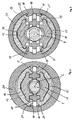
- the 4 and 5 show the cam mechanism with the divided dosing 11/12 and the piston rod 4 each in the same cross section, based on the dosing 11/12, but in different gear states.
- the same transmission states are in the 6 and 7 each shown in a three-dimensional section. What the mode of action of As far as the cam mechanism is concerned, the following should always be added to the FIGS. 4 to 7 directed.
- the sliders 15 and 16 are each conical on their outer jacket.
- the sliding sleeve 20 forms on its inner shell, which faces the conical surfaces of the sliders 15 and 16, a corresponding counter-cone.
- the cone outer surfaces of the sliders 15 and 16 and the surface of the mating cone of the sliding sleeve 20 are parallel to each other to form a uniformly thick cone gap over the entire cone surfaces.
- the sliding sleeve 20 forms two guideways 21 for the slider 15 and two guide tracks 22 for the slider 16.
- the sliders 15 and 16 form corresponding engagement tracks 18 which have sliding contact with the guideways 21 and 22.
- the guideways 21 are formed on the inner lateral surface of the sliding sleeve 20 on both sides of the longitudinal axis L diametrically opposite one another.
- the guideways 21 and 22 extend in the axial direction and each have a constant inclination with respect to the longitudinal axis L, ie the guideways 21 and 22 are straight.
- the guideways 21 are parallel to each other.
- the guideways 22 are parallel to each other. The in cross-section of FIGS.
- guideways 21 and 22 run in a longitudinal section of Fig. 1 seen in the feed direction V at an acute angle, which divides a parallel to the longitudinal axis L straight line in half, arrow toward each other.
- the sliders 15 and 16 are thus guided over their engaging tracks 18 on the guideways 21 and 22, the sliders 15 and 16 transverse to the longitudinal axis L, in the embodiment exactly perpendicular to the longitudinal axis L, away from each other or to each other.
- the first dosing member 11 is received in the slider 15 axially straight. Accordingly, the second dosing member 12 is axially straight in its slider 16 added.
- the sliders 15 and 16 have on their sides facing each other in cross-section on the left side and on the right side inwardly toward one another Stages 17 on.
- the slider 15 engages behind with its two webs 17, the first metering member 11, and the slider 16 engages behind with its two webs 17, the second metering member 12. If the two slides 15 and 16 are moved away from each other transversely to the longitudinal axis L, so are by the engaging behind webs 17th the two metering members 11 and 12 in the same way away from the longitudinal axis L away from each other and thereby moved out of engagement with the piston rod 4.
- the reservoir holding spring 37 is stretched between the piston rod holder 6 and the reservoir holder 30.
- the reservoir holding spring 37 presses the reservoir holder 30 against the rear edge of the container forming the reservoir R.
- the reservoir holding spring 37 pushes the container against a stop surface formed in the front housing portion 1.
- the arrangement of such a reservoir retaining spring 37 is common to compensate for length tolerances of the container, the housing sections 1, 2 and the components on which the container is supported in the longitudinal direction.
- the assembly of the transmission components 20, 25 and 30 and their arrangement relative to the piston rod holder 6 is best in Fig. 8 recognizable.
- the reservoir holder 30 has a circular cylindrical, front sleeve part with the shoulder 31. From the sleeve part protrude several shoes 32 back. At the rear End of each of the shoes 32 is a radially outwardly projecting locking cam 34 is formed. Further, each of the shoes 32 has side guides 33.
- the reservoir holder 30 can be inserted with its shoes 32 between a radially outer and a central sleeve part of the piston rod holder 6.
- the piston rod holder 6 in a sleeve bottom the shoes 32 corresponding recesses.
- the piston rod holder 6 and the reservoir holder 30 are connected to each other via the shoes 32 and the recesses secured against rotation.
- From the rear side of the driver 25 is pushed over the middle sleeve part of the piston rod holder 6 on the reservoir holder 30.
- From a rear sleeve part of the driver 25 project tongues 27 in number and arrangement of the shoes 32 accordingly.
- the locking cam 34 Depending on one of the tongues 27 is pushed onto one of the shoes 32 and latched by means of the locking cam 34, wherein the locking cams 34 engage in correspondingly formed on the tongues 27 recesses 28.
- the connection between the driver 25 and the reservoir holder 30 can be considered to be completely rigid.
- the sliding sleeve 20 has a rear sleeve part and a plurality of flexurally elastic tongues 23 which project from the sleeve part in the feed direction V and onto the driver 25.
- driving cam 24 are formed, which project from the tongues 23 radially outward.
- the entrainment of the sliding sleeve 20 during an axial movement of the driver 25 is effected by an engagement which is in the connected state between the driving cam 24 and a cam shoulder 26 which projects radially inwards at the rear end of the driver 25 and connected by the driving cam 24 in the Condition is underlaid.
- the engagement allows relative rotational movements about the longitudinal axis L.
- Fig. 8 also the displacement and non-rotating connection between the mechanism holder 5 and the piston rod holder 6 recognizable. From the sleeve part of the piston rod holder 6 projecting rearwardly elastic tongues 63 protrude with radially outwardly projecting locking cam 64. With the locking cam 64 of the piston rod holder 6 locked in corresponding recesses 52 of the mechanism holder 5. An anti-rotation between the mechanism holder 5 and the piston rod holder 6 is further by Engagement of an axially projecting from the mechanism holder 5 guide projection 62 into a guide recess 51 of the mechanism holder 5 is obtained.
- the mechanism holder 5 is displaceably connected to the rear housing section 2 and secured against rotation, so the same applies to the piston rod holder 6.
- the numbers that can be selected correspond to the selectable dosage units.
- the dose indicator sleeve 40 is connected to the dosing sleeve 7 axially straight slidably connected but secured against rotation with respect to the longitudinal axis L.
- the dose indicator sleeve 40 has at its rear end a plurality of radially projecting guide cams 43, which in corresponding guide grooves 7 b (FIG. Fig. 9 ) protrude on the inner circumferential surface of the dosing sleeve 7 and are axially straight in it.
- the dose indicator sleeve 40 is rotated about the longitudinal axis L due to this engagement.
- the dose indicator sleeve 40 Because of the threaded engagement with the mechanism holder 5, the dose indicator sleeve 40 thus screwed relative to the dose selection made by the rotational movement of the dosing sleeve 7 to the mechanism holder 5 and thus also relative to the rear housing portion 2 against the feed direction V to the rear.
- the dose indicator sleeve 40 protrudes with its internal thread 42 and the dose scale 41 forming portion in an annular gap which remains between the rear housing portion 2 and the mechanism holder 5.
- the rear housing section 2 has a window 3, through which the dose scale 41 can be read.
- the pitch of the internal thread 42 corresponds to the pitch of the spiral dose scale 41.
- the already mentioned locking member 45 is arranged, which is hereinafter referred to as a locking ring due to its shape.
- the locking ring 45 is secured against rotation in a sleeve part of a locking ring holder 47 and stored axially secured against displacement.
- the locking ring holder 47 is fixed to the mechanism holder 5 so as to be secured against rotation and displacement, via a guide surface 54 of the mechanism holder 5 and a latching connection formed between a latching cam 55 of the mechanism holder 5 and a recess 48 of the locking ring holder 47 ( Fig. 8 ).
- the reset counter cam 46 is free from the reset cam 44, ie there remains a radially clear distance between the reset cam 45 and the facing one Inner lateral surface of the dose indicator sleeve 40.
- the locking ring 45 is radially movable relative to the locking ring holder 47 radially to the longitudinal axis L.
- the Resetumblenocken 46 with respect to the longitudinal axis L diametrically opposite is arranged between the locking ring 45 and the locking ring holder 47, the spring element 49 which presses the locking ring 45 against the outer circumferential surface of the dosing and operating knob 8.
- the spring element 49 acts as a compression spring.
- Fig. 1 The device assumes an initial state in which the reservoir R is completely filled with the product and from which the dose selection can be made.
- the dose display sleeve 40 assumes its position corresponding to the zero dose, that is, through the window 3, the dosage corresponding to the zero dose can be read.
- the metering and actuating device 7/8/10 takes together with the piston rod 4 their rearmost position, in which the dose is selected.
- an axial, clear distance H 1 remains between the piston rod 4 and the piston K.
- An equal axial, clear distance H 2 remains between two axially facing abutment surfaces, one of which is formed by the piston rod holder 6 and the other of the transmission element 10 and define a front end position for the transmission element 10 and the piston rod 4.
- the axial, clear distance H 2 between this stop surface pair is the maximum stroke of the piston rod 4.
- the dose selection of the axial, clear distance H 1 between the piston K and the piston rod 4 is reduced. If the piston rod 4 is subsequently moved in the direction of advance V by the same length of stroke H 2 into its front end position, then the reduction in the clear distance H 1 between the piston rod 4 and the piston K of the dispensed dose corresponds to the reduction made in the dose selection product dosage.
- the dosing sleeve 7 is rotated relative to the rear housing section 2 about the longitudinal axis L.
- the metering and actuating knob 8 is rotated due to the rotation-secured engagement with the dosing sleeve 7.
- the piston rod 4 is axially straight from the piston rod holder 6 causes the rotational movement of the divided metering 11/12 via the threaded engagement directed in the feed direction V metering movement of the piston rod 4.
- the clear distance H 1 between the piston rod 4 and the piston K to shortened length corresponding to the selected product dose.
- the clear distance H 2 does not change here.
- the dose indicator sleeve 40 is taken because of the rotationally secured engagement in the Dosiermosterrorism of the dosing sleeve 7 and rotated relative to the mechanism holder 5 about the longitudinal axis L. Because of the threaded engagement between the mechanism holder 5 and the dose indicator sleeve 40, the rotational movement of the dose indicator sleeve 40 is superimposed against axial movement against the feed direction V. It should be noted only marginally that the pitch of the engaged threads 42 and 53 of the dose indicator sleeve 40 and the mechanical holder 5 is greater than the pitch of the engaged threads of the piston rod 4 and the split dosing member 11/12.
- the axial travel that the dose indicator sleeve 40 travels per revolution is greater than the axial travel by which the piston rod 4 is moved per revolution of the split metering member 11/12.
- This benefits the readability of the dose scale 41.
- the metering and actuating knob 8 is pressed in the feed direction V in the rear housing portion 2, that is actuated.
- the feed direction V is therefore at the same time the direction of actuation of the metering and actuation button.
- the dosing and operating knob 8 axially 29iebegeschreibt connected components, namely the transmission element 10, the split dosing 11/12 and because of the threaded engagement and the piston rod 4 in the feed direction by the stroke length H 2 moves.
- the piston K is advanced in the feed direction by a path length which corresponds to the shortening of the clear distance H 1 between the piston rod 4 and the piston K in comparison to the stroke H 2 , made by the dose selection.
- Fig. 2 shows the device in a final state in which the maximum distributable from the reservoir R by means of the device product amount has been distributed after repeated administration, ie the reservoir R is emptied.
- the metering and actuation button 8 has been pushed by the stroke length H 2 in the rear housing section 2.
- the groove 9 In this axial position of the metering and Betchan Trentsknopfts 8 is the groove 9 in a radial alignment under the locking ring 45.
- the groove 9 is slightly wider in the axial direction than the locking ring 45, at a compression of the metering and actuation button 8 still the locking ring 45 to be able to record.
- the locking ring 45 forms an axial stop for the compression movement of the metering and actuation button 8.
- its reset counter cam 46 radially extends onto the inner circumferential surface of the dose indicator sleeve 40 by retracting the locking ring 45 emotional. Since the locking ring 45 is axially non-movably connected to the mechanism holder 5 in the locking ring holder 47, the metering and actuation button 8 and thus together the piston rod 4 can not be moved back against the feed direction V, ie the locking ring 45 and the metering and actuation button 8 are in a lock intervention.
- the seated in the groove 9 locking ring 45 forms in locking engagement in the foremost position of the metering and actuating device 7/8/10 thus an axial lock for the metering and actuating device 7/8/10, the divided metering member 11/12 and the piston rod. 4
- the return spring 36 is axially tensioned in this final state to pressure. A relaxation of the return spring 36 is prevented by the axial lock formed by the locking ring 45.
- the two housing sections 1 and 2 are unscrewed. Due to the screwing an axial relative movement between the housing sections 1 and 2 takes place.
- the reservoir holder 30 is pressed in the housing 1/2 extending movement of the housing sections 1 and 2 relative to the piston rod holder 6 in the feed direction against a stop formed by the rear housing portion 2.
- a sufficiently large, clear distance remains axially before the start of the screwing movement to allow the axial movement of the reservoir holder 30 relative to the piston rod holder 6.
- the reservoir holder 30 takes in its taking place relative to the piston rod holder 6 axial movement of the driver 25 and the sliding sleeve 20 with. Due to the axial movement of the sliding sleeve 20, the two slides 15 and 16 ride on the inclined guideways 21 and 22 of the sliding sleeve 20 radially outwardly. In this movement radially outward, the sliders 15 and 16 of the mechanism holder 5 and the piston rod holder 6 are straight. Since the slider 15, the first metering member 11 and the Slider 16 engage behind the second metering member 12 with their webs 17, the first metering member 11 and the second metering member 12 in the same way radially apart and thereby moved out of the threaded engagement with the piston rod 4.
- the axial movement that the rear housing portion 2 makes relative to the front housing portion 1 to release the engagement of the piston rod 4 and the metering members 11 and 12 may be referred to as a disengagement movement. Due to the disengagement movement, the dosing members 11 and 12 are each moved into a position withdrawn from the piston rod 4. By the opposing engagement movement, in which the rear housing portion 2 performs an axial movement in the opposite direction relative to the first housing portion 2, the dosing members 11 and 12 are engaged again by the cam mechanism formed by the sliding sleeve 20 and the sliders 15 and 16 the piston rod 4 moves. The disengagement and the engagement movement takes place from the completely screwed together state of the housing sections 1 and 2 out in a first portion of the screwing. This first portion of the screwing is completed when the reservoir holder 30 is pressed by the reservoir holding spring 37 against the stop formed by the rear housing portion 2.
- Fig. 3 shows the device in a state in which the threaded engagement of the split metering member 11/12 solved with the piston rod 4 and the piston rod 4 thus in the piston rod holder 6 is axially freely displaceable.
- the rear housing section 2 has just completed its disengagement.
- the piston rod 4 has already been reset to its rearmost position.
- the piston rod 4 for example, by slightly tilting the entire device of the piston rod holder 6 guided slide back into the end position shown.
- the Dosierknopfs 8 protrudes in the feed direction inwardly from a rubber stopper, which gently dampens the sliding movement of the piston rod 4.
- the positions occupied by the metering members 11 and 12, the sliders 15 and 16, the sliding sleeve 20 and the reservoir holder 30 relative to the rear housing section 2 no longer change.
- the two housing sections 1 and 2 can completely unscrewed and the used reservoir R exchanged for a new one. After inserting a new reservoir R in the front housing section 1, the two housing sections 1 and 2 are screwed together again.
- the rear housing section 2 makes its engaging movement relative to the front housing section 1, in which the reservoir holder 30 comes into contact with the reservoir R or a reservoir holder and from there against the spring force of the reservoir holding spring 37 axially on the piston rod holder 6 is pressed too.
- the reservoir holder 30 presses on the driver 25 and the sliding sleeve 20 against the feed direction V to the rear.
- the sliders 15 and 16 are moved radially inwardly over their guide engagement with the sliding sleeve 20 until the synchronous engagement of the metering members 11 and 12 is restored to the piston rod 4.
- the dosing sleeve 7 is rotated about the longitudinal axis L in a direction of rotation indicating the dose indicator sleeve 40 in the zero dose position.
- the dose indicator sleeve 40 is rotated relative to the mechanism holder 5. Due to the threaded engagement with the mechanism holder. 5 the dose indicating sleeve 40 translates and rotates relative to the mechanism holder 5 and the rear housing portion 2 toward their zero dose position.
- this coupling is designed so that on the one hand, the movement of the metering and actuating device 7/8/10 is only possible if the dose indicator sleeve 40 assumes its zero-dose position, on the other hand, but to trigger the reset movement of the metering and actuating device 7/8 / 10 no further manipulations are required.
- the product dispenser of the embodiment is intended for an inhaler with which insulin is administered via the respiratory tract.
- the device serves to meter and dispense the product into a misting chamber. That in the Fuming chamber thus dosed present product is nebulized by a nebulizer or atomized and administered through a chamber outlet via the respiratory tract, preferably orally.
- the front end of the front housing section 1 is provided with a threaded connection G in order to be able to threadably connect the device to the misting chamber.
- the device can also be used directly as an injection device by screwing onto the front end of the front housing section 1 a needle holder with integrated injection needle of preferably 30 G or thinner, for example 31 G.
- the device could also be provided for a Druckinjektor and be connected in this case to an ejector of the Druckinjektors. The device would deliver the selected product dose to the ejector and the ejector would expel this product dose under high pressure through an injection nozzle.
Landscapes
- Health & Medical Sciences (AREA)
- Public Health (AREA)
- Veterinary Medicine (AREA)
- Anesthesiology (AREA)
- Biomedical Technology (AREA)
- Heart & Thoracic Surgery (AREA)
- Hematology (AREA)
- Life Sciences & Earth Sciences (AREA)
- Vascular Medicine (AREA)
- General Health & Medical Sciences (AREA)
- Engineering & Computer Science (AREA)
- Animal Behavior & Ethology (AREA)
- Infusion, Injection, And Reservoir Apparatuses (AREA)
- Containers And Packaging Bodies Having A Special Means To Remove Contents (AREA)
- Coating Apparatus (AREA)
- Pharmaceuticals Containing Other Organic And Inorganic Compounds (AREA)
- Acyclic And Carbocyclic Compounds In Medicinal Compositions (AREA)
- Medicines Containing Material From Animals Or Micro-Organisms (AREA)
- Nozzles (AREA)
- External Artificial Organs (AREA)
- Electrical Discharge Machining, Electrochemical Machining, And Combined Machining (AREA)
Abstract
Description
Die Erfindung betrifft eine Vorrichtung für eine dosierte Ausschüttung eines Produkts. Das Produkt kann unmittelbar bei der Ausschüttung verabreicht werden, beispielsweise durch Injektion. Die Vorrichtung kann aber auch in Verbindung mit einer Verabreichungseinrichtung verwendet werden, beispielsweise in Verbindung mit einer Druckinjektionseinrichtung oder insbesondere einer Zersteubungseinrichtung eines Inhalators. Mit der Produktausschüttung wird im zweiten Verwendungsfall die gewünschte Produktdosis eingestellt und in die nachgeschaltete, eigentliche Verabreichungseinrichtung ausgeschüttet.The invention relates to a device for a metered distribution of a product. The product can be administered immediately at the time of distribution, for example by injection. However, the device can also be used in conjunction with an administration device, for example in conjunction with a pressure injection device or in particular a Zersteubungseinrichtung an inhaler. With the product distribution, the desired product dose is set in the second use case and distributed in the downstream, actual administration device.
Bekannte Injektionsgeräte, wie eines beispielsweise in der
Die
Bei einer anderen bekannten Bauart von Produktausschüttvorrichtungen ist die Kolbenstange als Zahnstange und das Dosierglied als elastischer Schnapper ausgebildet, der in die Sägezähne der Kolbenstange eingreift. Bei Vorrichtungen dieser Art ist eine Rücksetzung der Kolbenstange im Allgemeinen überhaupt nicht möglich.In another known type of Produktausschüttvorrichtungen the piston rod is designed as a rack and the dosing as an elastic snapper which engages in the saw teeth of the piston rod. In devices of this type, a reset of the piston rod is generally not possible at all.
Es ist eine Aufgabe der Erfindung, eine Produktausschüttvorrichtung zu schaffen, die nach Vornahme einer Dosisauswahl rasch und bequem wieder in einen Ausgangszustand zurückgesetzt werden kann, den sie vor der Dosisauswahl eingenommen hat.It is an object of the invention to provide a product dispenser which, after making a dose selection, can be quickly and conveniently returned to an initial state that it has taken prior to dose selection.
Eine Produktausschüttvorrichtung, wie die Erfindung sie betrifft, weist ein Gehäuse, eine Kolbenstange, eine Dosier- und Betätigungseinrichtung und ein Dosierglied auf, das mit der Kolbenstange in einem Eingriff ist. Das Gehäuse weist einen Gehäuseabschnitt auf, der der Aufnahme eines produktgefüllten Reservoirs dient. Der betreffende Gehäuseabschnitt kann das Reservoir unmittelbar bilden. Bevorzugter bildet er jedoch einen Halter für ein einsetzbares Produktbehältnis. Das Reservoir weist einen Auslass auf und wird an einem von dem Auslass abgewandten Ende von einem Kolben verschlossen, der in eine Vorschubrichtung auf den Auslass zu verschiebbar ist, um das Produkt durch den Auslass zu verdrängen. Der Kolben kann fester Bestandteil der Vorrichtung sein. Der Kolben kann insbesondere jedoch Bestandteil eines Produktbehältnisses und zusammen mit dem Behältnis austauschbar sein, wie dies in der Selbstverabreichung üblich ist. So stellt die Selbstverabreichung im Rahmen einer Therapie, beispielsweise die Verabreichung von Insulin oder Wachstumshormonen, ein bevorzugtes Anwendungsgebiet der Erfindung dar.A Produktausschüttvorrichtung, as the invention relates, comprises a housing, a piston rod, a metering and actuating device and a metering member which is in engagement with the piston rod. The housing has a housing section which serves to receive a product-filled reservoir. The housing section in question can form the reservoir directly. However, more preferably, it forms a holder for an insertable product container. The reservoir has an outlet and is closed at an end remote from the outlet by a piston which is displaceable in a direction of advance towards the outlet to displace the product through the outlet. The piston can be an integral part of the device. In particular, however, the piston may be part of a product container and be interchangeable with the container, as is customary in self-administration. Thus, self-administration in the context of a therapy, for example the administration of insulin or growth hormones, represents a preferred field of application of the invention.
Die Dosier- und Betätigungseinrichtung wird von dem Gehäuse so gelagert, dass sie relativ zu dem Gehäuse eine Ausschüttbewegung in die Vorschubrichtung und eine Dosierbewegung ausführen kann. Das Dosierglied ist mit der Dosier- und Betätigungseinrichtung so in einem formschlüssigen Eingriff, dass es die Ausschüttbewegung exakt mitmacht. Ferner ist es mit der Kolbenstange in einem Eingriff. Der Eingriff der Dosier- und Betätigungseinrichtung mit dem Dosierglied und der Eingriff des Dosierglieds mit der Kolbenstange sind so, dass das Dosierglied durch die Dosierbewegung der Dosier- und Betätigungseinrichtung in eine Dosierbewegung relativ zu dem Gehäuse und relativ zu der Kolbenstange versetzt wird. So können die Dosier- und Betätigungseinrichtung und die Kolbenstange beispielsweise in Bezug auf eine Längsachse der Kolbenstange verdrehgesichert und axial relativ zueinander verschiebbar miteinander verbunden sein, während das Dosierglied im Gehäuse axial geradgeführt wird und mit der Kolbenstange in einem Gewindeeingriff ist. Die Dosierbewegung des Dosierglieds kann in diesem Fall eine Translationsbewegung gegen die Vorschubrichtung sein.The metering and actuating device is mounted by the housing so that it can perform a dispensing movement in the feed direction and a metering movement relative to the housing. The dosing member is in a positive engagement with the dosing and actuating device so that it exactly participates in the dispensing movement. Further, it is engaged with the piston rod. The engagement of the metering and actuating device with the metering member and the engagement of the metering member with the piston rod are such that the metering member is displaced by the metering movement of the metering and actuating device in a metering movement relative to the housing and relative to the piston rod. Thus, the metering and actuating device and the piston rod, for example, with respect to a longitudinal axis of the piston rod against rotation and axially relative to each other slidably connected to each other, while the dosing member is axially straight in the housing and is in threaded engagement with the piston rod. The dosing movement of the dosing member can be a translational movement in this case against the feed direction.
Vorzugsweise sind die Dosier- und Betätigungseinrichtung und das Dosierglied jedoch verdrehgesichert und in Bezug auf die Axialrichtung verschiebegesichert miteinander verbunden. Die Dosier- und Betätigungseinrichtung und das Dosierglied führen somit nicht nur die Ausschüttbewegung, sondern auch die Dosierbewegung gemeinsam aus. Der Eingriff, in dem das Dosierglied und die Kolbenstange sich befinden, lässt, wie in dem alternativen Beispielfall auch, die Dosierbewegung des Dosierglieds relativ zu der Kolbenstange zu und bewirkt die Mitnahme der Kolbenstange bei der Ausschüttbewegung.Preferably, however, the metering and actuating device and the dosing member are secured against rotation and connected to one another in a manner secured against displacement with respect to the axial direction. The metering and actuating device and the dosing thus perform not only the dispensing movement, but also the metering movement together. The engagement in which the dosing member and the piston rod are located, as in the alternative example also, the metering movement of the dosing relative to the piston rod and causes the entrainment of the piston rod in the dispensing movement.
In der
Das Dosierglied ist quer zu der Kolbenstange bewegbar, um den für die Dosisauswahl und die Ausschüttung bestehenden Eingriff mit der Kolbenstange lösen zu können. Wenn der Eingriff gelöst ist, kann die Kolbenstange gegen die Vorschubrichtung bis in eine hinterste Ausgangsposition zurück bewegt, d.h. zurückgesetzt, werden. In der hintersten Ausgangsposition steht wieder die gesamte, für die Dosierung wirksame Länge der Kolbenstange zur Verfügung.The dosing member is movable transversely to the piston rod in order to be able to disengage the engagement with the piston rod for dose selection and dispensing. When the engagement is released, the piston rod can be moved back against the advancing direction to a rearmost starting position, i. be reset. In the rearmost starting position, the entire effective length of the piston rod is again available.
Falls das Dosierglied ein Gewindeglied und die Kolbenstange dementsprechend eine Gewindestange ist, umgreift das Dosierglied in dem Gewindeeingriff die Kolbenstange über einen im Bogenmaß gemessenen Umfang von höchstens 180°, um die Querbewegung relativ zu der Kolbenstange zu ermöglichen. In einer bevorzugten Ausbildung als Gewindeglied ist das Dosierglied als axial geteilte Gewindemutter gebildet, vorzugsweise als geteilte Gewindemutter bestehend aus zwei Mutternhälften, die quer zu der Kolbenstange in entgegengesetzte Richtungen aus dem Eingriff bewegbar angeordnet sind.If the dosing member is a threaded member and the piston rod is accordingly a threaded rod, the dosing member in the threaded engagement engages around the piston rod over a radically measured circumference of at most 180 ° to allow transverse movement relative to the piston rod. In a preferred embodiment as a threaded member, the dosing member is formed as an axially divided nut, preferably as a split nut consisting of two nut halves, which are arranged transversely to the piston rod in opposite directions from the engagement movable.
Falls die Kolbenstange eine Zahnstange und das Dosierglied ein elastisch von der Kolbenstange abbiegbarer Schnapper oder eine Schnappereinrichtung mit mehreren solcher Schnapper ist, wird unter der Querbewegung des Dosierglieds zum Lösen des Eingriffs mit der Kolbenstange nicht die bei solchen Dosiergliedem übliche elastische Abbiegung zum Zwecke der Dosierung verstanden, sondern eine Querbewegung, bei der der oder die Schnapper bis in eine Ausrückposition bewegt werden, in der sie nicht durch ihre Elastizitätskraft in die Zahnlücken des Zahnstangenabschnitts der Kolbenstange hinein ragen, sondern frei von der Kolbenstange sind.If the piston rod is a toothed rack and the dosing member is a snap-off device which can be deflected elastically by the piston rod or a snap device with a plurality of such snap-action means, the transverse movement of the dosing member for releasing the engagement with the piston rod is not understood to be the usual elastic deflection for the purpose of dosing in such dosing members but a transverse movement in which the one or more snapper are moved to a disengaged position in which they do not protrude by their elasticity in the tooth gaps of the rack portion of the piston rod, but are free of the piston rod.
Die erfindungsgemäße Vorrichtung umfasst ferner ein Rücksetz-Betätigungselement, das mit dem Gehäuse derart verbunden ist, das es relativ zu dem Gehäuse eine Ausrück- und eine Einrückbewegung ausführen kann. Das Rücksetz-Betätigungselement bildet in bevorzugter Ausführung selbst einen zweiten Gehäuseabschnitt. Grundsätzlich kann es aber auch ein zusätzliches Element sein, das an dem Gehäuse bewegbar angebracht ist.The device according to the invention further comprises a reset actuator which is connected to the housing so that it can perform a disengagement and an engagement movement relative to the housing. The reset actuator forms in a preferred embodiment itself a second housing portion. In principle, however, it can also be an additional element which is movably mounted on the housing.
Das Rücksetz-Betätigungselement und das Dosierglied werden von einem Kurvengetriebe miteinander gekoppelt. Das Kurvengetriebe wandelt die Ausrückbewegung des Rücksetz-Betätigungselements in die Querbewegung des Dosierglieds um, die das Dosierglied aus dem mit der Kolbenstange bestehenden Eingriff führt. Ferner wandelt das Kurvengetriebe in die andere Richtung auch die Einrückbewegung des Rücksetz-Betätigungselements in die in den Eingriff mit der Kolbenstange zurückführende Querbewegung des Dosierglieds um. Die Querbewegung des Dosierglieds ist eine durch Formschluss geführte Bewegung entlang einer quer zu der Längsachse weisenden Führungsbahn, die im Folgenden als Querführungsbahn bezeichnet wird. Vorzugsweise wird unmittelbar das Dosierglied an der Querführungsbahn geführt. Das Dosierglied kann in dieser Ausführung einen Gleitstück bilden. Die Querführungsbahn schließt das Dosierglied oder gegebenenfalls ein mit dem Dosierglied verbundenes und an der Querführungsbahn geführtes Übertragungsstück vorzugsweise beidseitig ein, so dass Bewegungen des Dosierglieds in oder gegen die Vorschubrichtung bei der Querbewegung in und aus dem Eingriff mit der Kolbenstange bereits durch die Führung an der Querführungsbahn verhindert werden.The reset actuator and the metering member are coupled together by a cam gear. The cam gear converts the disengagement of the reset actuator in the transverse movement of the dosing member, which leads the dosing of the existing with the piston rod engagement. Further, the cam gear in the other direction also converts the engaging movement of the reset actuator into the transverse movement of the metering member back into engagement with the piston rod. The transverse movement of the dosing member is a guided by positive engagement movement along a transversely to the longitudinal axis facing guideway, which is referred to below as the transverse guideway. Preferably, the dosing member is guided directly on the transverse guideway. The dosing member can form a slider in this embodiment. The transverse guideway preferably closes the dosing member or optionally a transfer piece connected to the dosing member and guided on the transverse guideway on both sides, so that movements of the dosing member in or against the feed direction in the transverse movement in and out of engagement with the piston rod already by the guide on the transverse guideway be prevented.
Mittels des Kurvengetriebes, das mit dem Rücksetz-Betätigungselement und mit dem Dosierglied gekoppelt ist, kann die Rücksetzung der Kolbenstange bei geschlossenem Gehäuse vorgenommen werden. Es muss lediglich das Rücksetz-Betätigungselement relativ zu dem Gehäuse so betätigt werden, dass es seine Ausrückbewegung ausführt. Die Ausrückbewegung wird von dem Kurvengetriebe automatisch in die den Eingriff mit der Kolbenstange lösende Querbewegung des Dosierglieds übertragen. Gegebenenfalls wird die Vorrichtung noch in eine Position gebracht, in der bei gelöstem Eingriff die Kolbenstange unter der Wirkung der Schwerkraft gegen die Vorschubrichtung in eine Ausgangsposition fällt oder vorzugsweise gleitet.By means of the cam gear, which is coupled to the reset actuator and the dosing, the reset of the piston rod can be made with the housing closed. It only needs the reset actuator is actuated relative to the housing so that it carries out its disengagement. The disengagement movement is automatically transmitted by the cam gear into the transverse movement of the dosing member which releases the engagement with the piston rod. Optionally, the device is still brought into a position in which the piston rod falls under the action of gravity against the feed direction in a starting position or preferably slides with dissolved engagement.
In bevorzugten Ausführungen wird das Rücksetz-Betätigungselement, wie bereits erwähnt, von einem zweiten Gehäuseabschnitt gebildet. Der erste und der zweite Gehäuseabschnitt können Hülsenteile sein, die miteinander verschraubt sind. Dabei handelt es sich vorzugsweise um die beiden Gehäuseabschnitte, die für einen Reservoiraustausch oder ein Nachfüllen des Reservoirs sowieso auseinander geschraubt werden müssen. Die bei dem Auseinanderschrauben ausgeführte Relativbewegung zwischen den beiden Gehäuseabschnitten kann nämlich gleichzeitig auch die Ausrückbewegung sein. Die zwei Gehäuseabschnitte können grundsätzlich auch mittels einer Steckverbindung und/oder Rastverbindung miteinander verbunden sein, die eine Drehbewegung der Gehäuseabschnitte relativ zueinander nicht erfordert. Eine Verbindung mittels Gewindeeingriff ist zwischen den Gehäuseabschnitte jedoch zu bevorzugen, da hierdurch die Ausrückbewegung und die Einrückbewegung besonders fein kontrolliert ausgeführt werden können.In preferred embodiments, the reset actuator is, as already mentioned, formed by a second housing portion. The first and second housing sections may be sleeve parts which are bolted together. These are preferably the two housing sections, which anyway have to be screwed apart for a replacement of the reservoir or a refilling of the reservoir. The executed during the unscrewing relative movement between the two housing sections may namely at the same time be the disengagement. The two housing sections can in principle also by means of a plug connection and / or Locking connection be connected to each other, which does not require a rotational movement of the housing sections relative to each other. A connection by means of threaded engagement between the housing sections, however, to be preferred, since in this way the disengagement and the engagement movement can be performed very finely controlled.
Grundsätzlich muss das Rücksetz-Betätigungselement nicht selbst einen Gehäuseabschnitt bilden. Es kann auch ein Zusatzteil sein, das vorzugsweise mittels Gewindeeingriff mit dem Gehäuse, beispielsweise mit dem ersten Gehäuseabschnitt oder einem zweiten Gehäuseabschnitt, verbunden ist.Basically, the reset actuator does not have to form a housing section itself. It may also be an additional part, which is preferably connected by means of threaded engagement with the housing, for example with the first housing portion or a second housing portion.
Vorzugsweise bildet das Kurvengetriebe für die Kopplung des Rücksetz-Betätigungselements mit dem Dosierglied wenigstens eine weitere Führungsbahn. Ein mit dem Rücksetz-Betätigungselement verbundenes Getriebeeingangsglied und ein mit dem Dosierglied verbundenes Getriebeausgangsglied bilden ein Kurvenglied und ein Eingriffsglied des Kurvengetriebes. Das Kurvenglied ist mit einer Führungsbahn versehen, an der das Eingriffsglied in einem Führungseingriff geführt wird. Durch diesen Führungseingriff werden die Ausrückbewegung und die Einrückbewegung des Rücksetz-Betätigungselements in die zugeordnete Querbewegung des Dosierglieds relativ zu der Kolbenstange übertragen. Die Führungsbahn kann ein um die Kolbenstange verlaufender Kurvenbogen sein, an dem das Eingriffsglied bei einer zwischen den Kurvenglied und dem Eingriffsglied um die Kolbenstange stattfindenden Drehbewegung von der Kolbenstange abgehoben wird. Vorzugsweise verläuft die Führungsbahn jedoch in Längsrichtung der Kolbenstange und weist zu der Kolbenstange, d.h. zu der Längsrichtung der Kolbenstange, eine Neigung auf. Obgleich die Führungsbahn auch in dieser Ausbildung gekrümmt sein kann, weist die Neigung jedoch vorzugsweise einen konstanten Neigungswinkel auf. Besonders bevorzugt ist die Führungsbahn kontinuierlich, d.h. ohne Knickstellen und insbesondere ohne Sprünge, geneigt.Preferably, the cam gear for the coupling of the reset actuator with the dosing at least one further guideway. A transmission input member connected to the reset actuator and a transmission output member connected to the dosing member form a cam member and an engagement member of the cam gear. The cam member is provided with a guide track on which the engagement member is guided in a guide engagement. Through this guiding engagement, the disengagement movement and the engagement movement of the reset actuating element are transferred into the associated transverse movement of the dosing member relative to the piston rod. The guideway may be a curve arc running around the piston rod, on which the engagement member is lifted off the piston rod at a rotational movement taking place between the cam member and the engagement member about the piston rod. Preferably, however, the guideway extends in the longitudinal direction of the piston rod and faces the piston rod, i. to the longitudinal direction of the piston rod, an inclination. Although the guideway may also be curved in this embodiment, the inclination preferably has a constant angle of inclination. More preferably, the guideway is continuous, i. without kinks and in particular without cracks, inclined.
In bevorzugter Ausführung sind das Dosierglied und das Getriebeausgangsglied separate Körper, die relativ zueinander in Längsrichtung der Kolbenstange bewegbar sind. Grundsätzlich wäre es jedoch auch denkbar, das Dosierglied und das Getriebeausgangsglied einteilig auszubilden. In der bevorzugten zweiteiligen Ausbildung hintergreift das Getriebeausgangsglied das Dosierglied quer zu einer Senkrechten auf eine Längsachse der Kolbenstange, um das Dosierglied aus dem Eingriff mit der Kolbenstange herauszuziehen.In a preferred embodiment, the dosing member and the transmission output member are separate bodies which are movable relative to each other in the longitudinal direction of the piston rod. In principle, however, it would also be conceivable to use the dosing member and the Gearbox output member in one piece form. In the preferred two-part embodiment, the transmission output member engages the dosing member transversely to a perpendicular to a longitudinal axis of the piston rod to withdraw the dosing member from engagement with the piston rod.
Das Rücksetz-Betätigungselement und das Getriebeeingangsglied sind in ebenfalls bevorzugter Ausführung separate Körper. Grundsätzlich gilt jedoch auch hier, das das Rücksetz-Betätigungselement und das Getriebeeingangsglied einteilig ausgeführt sein können. In der bevorzugten zweiteiligen Ausführung sind das Rücksetz-Betätigungselement und das Getriebeeingangsglied vorzugsweise so miteinander verbunden, dass sie entlang der Längsachse der Kolbenstange relativ zueinander bewegbar und/oder um die Längsachse der Kolbenstange relativ zueinander drehbar sind. Die Bewegbarkeit des Getriebeeingangsglieds relativ zu dem Rücksetz-Betätigungselement ist insbesondere dann von Vorteil, wenn das Rücksetz-Betätigungselement einen Abschnitt des Gehäuses bildet.The reset actuator and the transmission input member are also in a preferred embodiment separate body. Basically, however, also applies here that the reset actuator and the transmission input member can be made in one piece. In the preferred two-part embodiment, the reset actuator and the transmission input member are preferably interconnected so as to be movable relative to each other along the longitudinal axis of the piston rod and / or rotatable relative to each other about the longitudinal axis of the piston rod. The mobility of the transmission input member relative to the reset actuator is particularly advantageous when the reset actuator forms a portion of the housing.
Besonders bevorzugt wird, wenn ein Federelement vorgesehen und so angeordnet ist, dass es durch die Einrückbewegung des Rückstell-Betätigungselements gespannt wird und bei der Ausrückbewegung aufgrund seiner Spannkraft die Relativbewegung zwischen dem Getriebeeingangsglied und dem Getriebeausgangsglied bewirkt. Dieses Federelement kann insbesondere von einer Ausgleichsfeder gebildet werden, wie sie üblicherweise verwendet wird, um ein mit dem Produkt gefülltes Behältnis in Vorschubrichtung gegen das Gehäuse auf Anschlag zu drücken. Solche Ausgleichsfedern dienen im allgemeinen dazu, Längentoleranzen zwischen einem von dem Gehäuse aufgenommenen Produktbehältnis und anderen Komponenten der Vorrichtung auszugleichen. Mit solch einer Ausgleichsfeder kann vorteilhafterweise die Relativbewegung zwischen dem Getriebeeingangsglied und dem Getriebeausgangsglied bewirkt werden. Dies ist auf einfache Weise dann möglich, wenn die Relativbewegung parallel zu der Längsachse der Kolbenstange stattfindet oder eine axiale Bewegungskomponente umfasst.It is particularly preferred if a spring element is provided and arranged so that it is tensioned by the engagement movement of the return actuator and causes the relative movement between the transmission input member and the transmission output member in the disengagement movement due to its clamping force. This spring element can be formed in particular by a compensating spring, as it is commonly used to press a container filled with the product in the feed direction against the housing to stop. Such compensating springs generally serve to compensate for length tolerances between a product container received by the housing and other components of the device. With such a compensating spring, the relative movement between the transmission input member and the transmission output member can advantageously be effected. This is possible in a simple manner when the relative movement takes place parallel to the longitudinal axis of the piston rod or comprises an axial movement component.
Weitere bevorzugte Merkmale werden in den Unteransprüchen beschrieben.Further preferred features are described in the subclaims.
Nachfolgend wird die Erfindung anhand eines Ausführungsbeispiels erläutert. Es zeigen:
- Fig. 1
- eine Produktausschüttvorrichtung in einem Ausgangszustand vor einer ersten Auswahl einer Produktdosis,
- Fig. 2
- die Produktausschüttvorrichtung in einem Endzustand, in dem eine Kolbenstange der Vorrichtung eine vorderste Position einnimmt und mit einem Dosierglied in Eingriff ist,
- Fig. 3
- die Produktausschüttvorrichtung in einem Zustand, in dem die Kolbenstange und das Dosierglied außer Eingriff sind und die Kolbenstange in eine hinterste Ausgangsposition zurückgesetzt worden ist,
- Fig. 4
- den Querschnitt A-A der
Fig. 2 - Fig. 5
- den Querschnitt B-B der
Fig. 3 - Fig. 6
- die Kolbenstange, das Dosierglied und Getriebeglieder eines Kurvengetriebes in einem dreidimensionalen Schnitt, wobei die Kolbenstange und das Dosierglied in Eingriff sind,
- Fig. 7
- die Kolbenstange, das Dosierglied und die Getriebeglieder in einem dreidimensionalen Schnitt, wobei die Kolbenstange und das Dosierglied außer Eingriff sind,
- Fig. 8
- Komponenten der Vorrichtung in dreidimensionaler Darstellung,
- Fig. 9
- eine Dosisanzeigehülse und mit der Dosisanzeigehülse zusammenwirkende Komponenten in dreidimensionaler Darstellung und
- Fig. 10
- die Dosisanzeigehülse in mehreren Darstellungen.
- Fig. 1
- a product dispenser in an initial state prior to a first selection of a product dose,
- Fig. 2
- the product discharge device in a final state in which a piston rod of the device occupies a foremost position and is engaged with a dosing member,
- Fig. 3
- the product discharge device in a state in which the piston rod and the dosing member are disengaged and the piston rod has been reset to a rearmost starting position,
- Fig. 4
- the cross section AA of
Fig. 2 - Fig. 5
- the cross section BB of
Fig. 3 - Fig. 6
- the piston rod, the dosing member and gear members of a cam gear in a three-dimensional section, wherein the piston rod and the dosing member are in engagement,
- Fig. 7
- the piston rod, the dosing member and the gear members in a three-dimensional section, wherein the piston rod and the dosing member are disengaged,
- Fig. 8
- Components of the device in three-dimensional representation,
- Fig. 9
- a dose display sleeve and cooperating with the dose display sleeve components in three-dimensional representation and
- Fig. 10
- the dose indicator sleeve in several representations.
Die Vorrichtung weist ein zweiteiliges Gehäuse mit einem ersten, vorderen Gehäuseabschnitt 1 und einem zweiten, hinteren Gehäuseabschnitt 2 auf, die je als Hülsenteil geformt sind. Die beiden Gehäuseabschnitte 1 und 2 sind miteinander verschraubt. Der vordere Gehäuseabschnitt 1 enthält ein mit dem Produkt gefülltes Reservoir R. Das Reservoir R wird von einem austauschbaren Behältnis, im Ausführungsbeispiel von einer hohlzylindrischen Ampulle gebildet. Das Behältnis wird von hinten in den vorderen Gehäuseabschnitt 1 bis gegen einen von dem vorderen Gehäuseabschnitt 1 gebildeten Anschlag eingeschoben. Das Behältnis weist an seinem vorderen Ende einen Auslass A auf, der von einem Septum steril abschlossen wird. Um das Produkt aus dem derart gebildeten Reservoir R ausschütten zu können wird eine Kanüle durch das Septum bis in den Auslass A eingeführt. An seinem hinteren Ende ist das Reservoir R von einem Kolben K dicht verschlossen. Durch Vorschub des Kolbens K entlang einer Längsachse L in eine Vorschubrichtung V auf den Auslass A zu wird Produkt aus dem Reservoir R verdrängt, d.h. durch den Auslass A ausgeschüttet.The device has a two-part housing with a first,
Die Bewegung des Kolbens K in die Vorschubrichtung V wird mittels einer Kolbenstange 4 bewirkt, die von dem Gehäuse 1/2 entlang der Längsachse L, d.h. axial, geradgeführt wird. Die Kolbenstange 4 ist mit einer Dosier- und Betätigungseinrichtung gekoppelt. Die Dosier- und Betätigungseinrichtung wird gebildet von einer Dosierhülse 7, einem hülsenförmigen Dosier- und Betätigungsknopf 8 und einem hülsenförmigen Übertragungselement 10. Mit dieser Dosier- und Betätigungseinrichtung 7/8/10 ist ein geteiltes Dosierglied 11/12 verbunden. Das Dosierglied 11/12 ist axial in zwei separate, gleiche Teile geteilt. Die beiden Teile werden im folgenden als erstes Dosierglied 11 und als zweites Dosierglied 12 bezeichnet. Das erste Dosierglied 11 und das zweite Dosierglied 12 sind mit der als Gewindestange ausgebildeten Kolbenstange 4 je in einem Gewindeeingriff um die Längsachse L, die gleichzeitig auch die Längsachse der Kolbenstange 4 ist. Das erste Dosierglied 11 und das zweite Dosierglied 12 sind mit dem Übertragungselement 10 axial verschiebegesichert und in Bezug auf Verdrehungen um die Längsachse L verdrehgesichert verbunden. Allerdings ist sowohl das erste Dosierglied 11 als auch das zweite Dosierglied 12 relativ zu dem Dosierelement 10 und insbesondere relativ zu der Kolbenstange 4 in eine Richtung quer zu der Längsachse L bewegbar. Für die Querbewegbarkeit werden das erste Dosierglied 11 und das zweite Dosierglied 12 von dem Übertragungselement 10 geradgeführt, indem das Übertragungselement 10 für die beiden Dosierglieder 11 und 12 je einen quer zu der Längsachse L weisenden Führungsschacht bildet, der gleichzeitig auch als axiale Verschiebesicherung und Verdrehsicherung wirkt. Wie besser beispielsweise anhand der
In Bezug auf die Form, die Funktion und das Zusammenwirken der für die Dosierung und Ausschüttung des Produkts zusammenwirkenden Komponenten sei ergänzend stets auf die
Der Dosier- und Betätigungsknopf 8 ist mit dem Übertragungselement 10- lösbar verbunden. Der Dosier- und Betätigungsknopf 8 ist aus mehreren Einzelteilen zusammengesetzt, nämlich einem aus dem hinteren Gehäuseabschnitt 2 herausragenden äußeren Hülsenteil 8a, einem eingesetzten inneren Hülsenteil 8b, einem von hinten in das äußere Hülsenteil 8a eingesteckten und verrasteten Endknopf 8c und einer zwischen dem Endknopf 8c und dem inneren Hülsenteil 8b axial gespannten Feder 8d. Das innere Hülsenteil 8b dient der Befestigung des Dosier- und Betätigungsknopfs 8 an dem Übertragungselement 10 und wird deshalb im Folgenden auch als Befestigungsteil 8b bezeichnet. Das äußere Hülsenteil 8a ist für den Verwender für die Betätigung des Verabreichungsgeräts zugänglich und wird deshalb im Folgenden auch als Betätigungsteil 8a bezeichnet. Das Betätigungsteil 8a ist mit dem Endknopf 8c verschiebegesichert verbunden und über die auf Druck gespannte Feder 8d an dem Befestigungsteil 8b abgestützt. Das Betätigungsteil 8a ist relativ zu dem Befestigungsteil 8b und deshalb auch relativ zu dem Übertragungselement 10 in und gegen die Vorschubrichtung V bewegbar. Die Feder 8d drückt das Betätigungsteil 8a entgegen der Vorschubrichtung V auf Anschlag gegen das Befestigungsteil 8b, so dass es relativ zu dem Befestigungsteil 8b die in den
Zu erwähnen ist noch, dass an der Außenmantelfläche des Dosier- und Betätigungsknopfs 8, im Ausführungsbeispiel an der Außenmantelfläche des äußeren Hülsenteils 8a, in einem das Übertragungselement 10 umgebenden Abschnitt eine umlaufende Nut 9 geformt ist. Diese Nut 9 wirkt mit einem als Ring gebildeten Sperrglied 45 zusammen, das die Außenmantelfläche des Dosier- und Betätigungsknopfs 8 umgibt und mittels einem Federelement 49 nach radial einwärts gegen die Außenmantelfläche des Dosier- und Betätigungsknopfs 8 gespannt wird.It should also be mentioned that a peripheral groove 9 is formed on the outer circumferential surface of the metering and
Die Dosierhülse 7 ist an dem hinteren Ende des hinteren Gehäuseabschnitts 2 angebracht und um die Längsachse L relativ zu dem hinteren Gehäuseabschnitt 2 drehbar. Die Dosierhülse 7 bildet an ihrem hinteren Ende einen nach radial innen ragenden Kragen, der über seinen Innenumfang gleichmäßig verteilt Zacken 7a bildet (
Ein Kolbenstangenhalter 6 bildet eine axiale Geradführung für die Kolbenstange 4. Der Kolbenstangenhalter 6 ist mit dem hinteren Gehäuseabschnitt 2 nicht bewegbar verbunden, insbesondere ist der Kolbenstangenhalter 6 relativ zu dem hinteren Gehäuseabschnitt 2 weder axial bewegbar noch um die Längsachse L verdrehbar. Zwischen dem Kolbenstangenhalter 6 und der Kolbenstange 4 sind ausschließlich axiale Relativbewegungen möglich. Auf diese Weise ist die Kolbenstange 4 relativ zu dem hinteren Gehäuseabschnitt 2 axial geradgeführt.A
Radial über dem ersten Dosierglied 11 ist ein Gleitstück 15 und radial über dem zweiten Dosierglied 12 ist ein weiteres Gleitstück 16 je axial verschiebegesichert, aber radial geradgeführt und in diesem Sinne radial bewegbar zwischen einem rückwärtigen Ende des Kolbenstangenhalters 6 und einem radial nach innen ragenden Kragen eines Mechanikhalters 5 gelagert. Die Gleitstücke 15 und 16 haben die gleiche Form und erfüllen die gleiche Funktion je in Bezug auf das zugeordnete erste Dosierglied 11 und zweite Dosierglied 12. Die Anordnung der Gleitstücke 15 und 16 ist symmetrisch zu der Längsachse L. Der Mechanikhalter 5 ist mit dem hinteren Gehäuseabschnitt 2 unbeweglich verbunden, insbesondere ist er relativ zu dem hinteren Gehäuseabschnitt 2 axial nicht bewegbar, wofür die Dreiviertel-Rippe 56 als Anschlag dient, und um die Längsachse L nicht verdrehbar.Radially above the
Die Gleitstücke 15 und 16 bilden weitere Getriebeglieder des Kurvengetriebes. Da sie je mit einem der Dosierglieder 11 und 12 in einem unmittelbaren Eingriff stehen, werden sie im Folgenden als die Getriebeausgangsglieder des Kurvengetriebes bezeichnet. Sie wirken je mit einem Getriebeeingangsglied 20 zusammen, das als Gleithülse ausgebildet ist und im Folgenden unter dieser Bezeichnung in Bezug genommen wird. Die Gleithülse 20 bildet ein weiteres Kurvenglied und die beiden Gleitstücke 15 und 16 bilden je ein Eingriffsglied des Kurvengetriebes. Die Gleithülse 20 ist relativ zu dem ersten Dosierglied 11 und zweiten Dosierglied 12, den beiden Gleitstücken 15 und 16 und relativ zu dem hinteren Gehäuseabschnitt 2 axial bewegbar. Relativ zu dem hinteren Gehäuseabschnitt 2 ist sie ferner um die Längsachse L verdrehbar. Der Mechanikhalter 5 bildet mit einer kreiszylindrischen Innenmantelfläche ein Drehgleitlager und eine axiale Geradführung für die Gleithülse 20.The
Die
Die Gleitstücke 15 und 16 sind an ihrem Außenmantel je konisch. Die Gleithülse 20 bildet an ihrem Innenmantel, der den Konusflächen der Gleitstücke 15 und 16 zugewandt ist, einen entsprechenden Gegenkonus. Die Konusaussenflächen der Gleitstücke 15 und 16 und die Fläche des Gegenkonus der Gleithülse 20 sind zueinander parallel unter Ausbildung eines über die gesamten Konusflächen gleichmäßig dicken Konusspalts.The
Wie am besten in den
Das erste Dosierglied 11 ist in dem Gleitstück 15 axial geradgeführt aufgenommen. Entsprechend ist das zweite Dosierglied 12 axial geradgeführt in seinem Gleitstück 16 aufgenommen. Die Gleitstücke 15 und 16 weisen an ihren einander zugewandten Unterseiten im Querschnitt linksseitig und rechtsseitig nach innen aufeinander zu ragende Stege 17 auf. Das Gleitstück 15 hintergreift mit seinen beiden Stegen 17 das erste Dosierglied 11, und das Gleitstück 16 hintergreift mit seinen beiden Stegen 17 das zweite Dosierglied 12. Werden die beiden Gleitstücke 15 und 16 quer zur Längsachse L voneinander wegbewegt, so werden durch die hintergreifenden Stege 17 die beiden Dosierglieder 11 und 12 in gleicher Weise quer zu der Längsachse L voneinander weg und dadurch aus dem Eingriff mit der Kolbenstange 4 bewegt. Bei einer Querbewegung der Gleitstücke 15 und 16 aufeinander zu drücken die Gleitstücke 15 und 16 über ihre Innenmantelflächen auch wieder die Dosierglieder 11 und 12 auf einander zu und dadurch wieder in den Eingriff mit der Kolbenstange 4. Wie bereits erwähnt, sind die Dosierglieder 11 und 12 in Ihrem jeweiligen Gleitstück 15 und 16 axial geradverschiebbar geführt. Die Stege 17 bilden für die Geradführung Führungsbahnen, und die Dosierglieder 11 und 12 bilden daran geführte Eingriffsbahnen 13, die von den Stegen 17 hintergriffen werden.The
Der in dem Zustand der
Um die axiale Relativbewegung zwischen den Gehäuseabschnitten 1 und 2 zum Lösen des Eingriffs nutzen zu können, ist die Gleithülse 20 mit dem vorderen Gehäuseabschnitt 1 verbunden, und zwar derart, das sie dessen axiale Bewegung relativ zu dem hinteren Gehäuseabschnitt mitmacht, während die Gleitstücke 15 und 16 ihre Axialposition relativ zu dem hinteren Gehäuseabschnitt 2 beibehalten. Für die axiale Verschiebesicherung der Gleitstücke 15 und 16 sorgt, wie gesagt, deren Lagerung zwischen dem Mechanikhalter 5 und dem Kolbenstangenhalter 6. Die Kopplung der Gleithülle 20 an den vorderen Gehäuseabschnitt 1 bildet eine Reservoirhaltefeder 37, die im vollkommen zusammengeschraubten Zustand der beiden Gehäuseabschnitte 1 und 2 axial zwischen dem Kolbenstangenhalter 6 und einem Reservoirhalter 30 auf Druck gespannt ist. Hierfür ist die Reservoirhaltefeder 37 zwischen dem Kolbenstangenhalter 6 und dem Reservoirhalter 30 gespannt. Die Reservoirhaltefeder 37 drückt den Reservoirhalter 30 gegen den rückwärtigen Rand des Behältnisses, das das Reservoir R bildet. Die Reservoirhaltefeder 37 drückt das Behältnis gegen eine in dem vorderen Gehäuseabschnitt 1 gebildete Anschlagfläche. Die Anordnung solch einer Reservoirhaltefeder 37 ist üblich, um Längentoleranzen des Behältnisses, der Gehäuseabschnitte 1, 2 und den Komponenten auszugleichen, an denen das Behältnis in Längsrichtung abgestützt ist.In order to use the axial relative movement between the
An dem Reservoirhalter 30 ist ein Mitnehmer 25 verschiebe- und verdrehgesichert befestigt. Der Mitnehmer 25 bildet ein Übertragungsglied zwischen dem Reservoirhalter 30 und der Gleithülse 20, wenn der Reservoirhalter 30 aufgrund der Federkraft der Reservoirhaltefeder 37 einer axialen Bewegung des vorderen Gehäuseabschnitts 1 folgt. Die Gleithülse 20 und der Mitnehmer 25 hintergreifen einander derart, dass die Gleithülse 20 bei der Axialbewegung von dem Mitnehmer 25 mitgenommen wird. Im Ausführungsbeispiel ist zwischen der Gleithülse 20 und dem Mitnehmer 25 eine Toleranzausgleichsfeder 38 in axialer Richtung gespannt. Grundsätzlich könnten die Gleithülse 20 und der Mitnehmer 25 jedoch auch in Bezug auf die axiale Richtung starr miteinander verbunden sein. Allerdings ist zwischen der Gleithülse 20 und dem Mitnehmer 25 eine Drehbewegung um die Längsachse L möglich. Insofern ist zwischen der Gleithülse 20 und dem Mitnehmer 25 das Drehgelenk zwischen der Dosier- und Betätigungseinrichtung 7/8/10 und dem hinteren Gehäuseabschnitt 2 gebildet.At the
Der Zusammenbau der Getriebekomponenten 20, 25 und 30 und deren Anordnung relativ zu dem Kolbenstangenhalter 6 ist am besten in
Die Gleithülse 20 weist ein rückwärtiges Hülsenteil und eine Mehrzahl von biegeelastischen Zungen 23 auf, die von dem Hülsenteil in Vorschubrichtung V ab und auf den Mitnehmer 25 zu ragen. An den vorderen Enden der Zungen 23 sind Mitnehmernocken 24 gebildet, die von den Zungen 23 nach radial außen abragen. Die Mitnahme der Gleithülse 20 bei einer Axialbewegung des Mitnehmer 25 wird durch einen Eingriff bewirkt, der im verbundenen Zustand zwischen den Mitnehmernocken 24 und einer Mitnehmerschulter 26 besteht, die an dem rückwärtigen Ende des Mitnehmers 25 nach radial innen vorragt und von den Mitnehmernocken 24 im verbundenen Zustand hintergriffen wird. Gleichzeitig ermöglicht der Eingriff Relativdrehbewegungen um die Längsachse L.The sliding
Ferner ist in
Zwischen dem Kolbenstangenhalter 6 und dem Übertragungselement 10 der Dosier- und Betätigungseinrichtung 7/8/10 ist eine Rückstellfeder 36 axial gespannt. Die Rückstellfeder 36 dient der Rückführung der Dosier- und Betätigungseinrichtung 7/8/10, des geteilten Dosierglieds 11/12 und der Kolbenstange 4 nach einer Produktausschüttung.Between the
Die Vorrichtung umfasst ferner eine Dosisanzeigehülse 40, die an Ihrer Außenmantelfläche mit einer Dosisskala 41 versehen ist. Die Dosisanzeigehülse 40 ist in den
Die Dosisanzeigehülse 40 ragt mit ihrem das Innengewinde 42 und die Dosisskala 41 bildenden Abschnitt in einen Ringspalt, der zwischen dem hinteren Gehäuseabschnitt 2 und dem Mechanikhalter 5 verbleibt. In dem Abschnitt, der der Dosisskala 41 radial außen gegenüber liegt, weist der hintere Gehäuseabschnitt 2 ein Fenster 3 auf, durch das die Dosisskala 41 abgelesen werden kann. Die Steigung des Innengewindes 42 entspricht der Steigung der spiraligen Dosisskala 41.The device further comprises a
The
Radial einwärts von einem Längsabschnitt der Dosisanzeigehülse 40, der über den Mechanikhalter 5 nach hinten hinaus ragt, ist das bereits erwähnte Sperrglied 45 angeordnet, das seiner Form wegen im Folgenden als Sperrring bezeichnet wird. Der Sperrring 45 ist in einem Hülsenteil eines Sperrringhalters 47 verdrehgesichert und axial verschiebegesichert gelagert. Der Sperrringhalter 47 ist an dem Mechanikhalter 5 verdreh- und verschiebegesichert befestigt, und zwar über eine Führungsfläche 54 des Mechanikhalters 5 und eine Rastverbindung, die zwischen einem Rastnocken 55 des Mechanikhalters 5 und einer Ausnehmung 48 des Sperrringhalters 47 gebildet wird (
Der Sperrring 45 bildet einen Resetgegennocken 46, der von der äußeren Mantelfläche des Sperrrings 45 nach radial außen auf die Dosisanzeigehülse 40 zu vorragt. Von der zugewandten Innenmantelfläche der Dosisanzeigehülse 40 ragt nach radial einwärts ein Resetnocken 44 ab (
Der Sperrring 45 ist relativ zu dem Sperrringhalter 47 radial zu der Längsachse L geradbewegbar. Dem Resetgegennocken 46 in Bezug auf die Längsachse L diametral gegenüber ist zwischen dem Sperrring 45 und dem Sperrringhalter 47 das Federelement 49 angeordnet, das den Sperring 45 gegen die Außenmantelfläche des Dosier- und Betätigungsknopfs 8 drückt. Das Federelement 49 wirkt als Druckfeder.The locking
Die Funktionsweise der Vorrichtung wird nachfolgend anhand der
In
Das geteilte Dosierglied 11/12 ist über die Dosier- und Betätigungseinrichtung 7/8/10 so mit der Dosisanzeigehülse 40 gekoppelt, dass der axiale Abstand H1 zwischen dem Kolben K und der Kolbenstange 4 maximal ist, d.h. H1 = H2, wenn die Dosisanzeigehülse 40 ihre Nulldosis-Position einnimmt.The divided
Zur Auswahl der Dosis wird die Dosierhülse 7 relativ zu dem hinteren Gehäuseabschnitt 2 um die Längsachse L gedreht. Hierbei wird der Dosier- und Betätigungsknopf 8 aufgrund des verdrehgesicherten Eingriffs mit der Dosierhülse 7 mitgedreht. Wegen der verdrehgesicherten Verbindungen drehen das Übertragungselement 10 und damit zusammen zwangsweise auch das geteilte Dosierglied 11/12 mit. Da die Kolbenstange 4 von dem Kolbenstangenhalter 6 axial geradgeführt wird, bewirkt die Drehbewegung des geteilten Dosierglieds 11/12 über den Gewindeeingriff eine in Vorschubrichtung V gerichtete Dosierbewegung der Kolbenstange 4. Hierdurch wird der lichte Abstand H1 zwischen der Kolbenstange 4 und dem Kolben K um eine der ausgewählten Produktdosis entsprechende Länge verkürzt. Der lichte Abstand H2 verändert sich hierbei nicht.To select the dose, the
Die Dosisanzeigehülse 40 wird wegen des verdrehgesicherten Eingriffs bei der Dosierdrehbewegung von der Dosierhülse 7 mitgenommen und relativ zu dem Mechanikhalter 5 um die Längsachse L verdreht. Wegen des Gewindeeingriffs zwischen dem Mechanikhalter 5 und der Dosisanzeigehülse 40 ist der Drehbewegung der Dosisanzeigehülse 40 eine Axialbewegung gegen die Vorschubrichtung V überlagert. Nur am Rande sei erwähnt, dass die Steigung der im Eingriff befindlichen Gewinde 42 und 53 der Dosisanzeigehülse 40 und des Mechanikhalters 5 größer ist als die Steigung der im Eingriff befindlichen Gewinde der Kolbenstange 4 und des geteilten Dosierglieds 11/12. Entsprechend ist der axiale Weg, den die Dosisanzeigehülse 40 pro Umdrehung zurücklegt größer als der axiale Weg, um den die Kolbenstange 4 pro Umdrehung des geteilten Dosierglieds 11/12 bewegt wird. Dies kommt der Ablesbarkeit der Dosisskala 41 zugute. Sobald die Dosisanzeigehülse 40 relativ zu dem Mechanikhalter 5 um wenigstens eine Dosiseinheit aus ihrer Nulldosis-Position bewegt wurde, ist der Sperrring 45 von dem Resetnocken 44 frei. Die durch das Fenster 3 auf der Dosisskala 41 ablesbare Dosisangabe entspricht der axialen Länge, um die der Abstand H1 durch die Dosierbewegung verkürzt ist.The
Um die gewählte Produktdosis durch den Auslass A des Reservoirs R auszuschütten, wird der Dosier- und Betätigungsknopf 8 in die Vorschubrichtung V in den hinteren Gehäuseabschnitt 2 hineingedrückt, d.h. betätigt. Die Vorschubrichtung V ist daher auch gleichzeitig die Betätigungsrichtung des Dosier- und Betätigungsknopfs. Durch die Betätigung werden auch die mit dem Dosier- und Betätigungsknopf 8 axial verschiebegesichert verbundenen Komponeten, nämlich das Übertragungselement 10, das geteilte Dosierglied 11/12 und wegen des Gewindeeingriffs auch die Kolbenstange 4 in Vorschubrichtung um die Hublänge H2 bewegt. Der Kolben K wird bei dieser Hubbewegung in Vorschubrichtung um eine Weglänge vorgeschoben, die der durch die Dosisauswahl vorgenommenen Verkürzung des lichten Abstands H1 zwischen der Kolbenstange 4 und dem Kolben K im Vergleich zu dem Hub H2 entspricht.To pour out the selected product dose through the outlet A of the reservoir R, the metering and
Um das entleerte Reservoir R gegen ein neues Reservoir R auszutauschen, werden die beiden Gehäuseabschnitte 1 und 2 auseinandergeschraubt. Aufgrund des Schraubvorgangs findet eine axiale Relativbewegung zwischen den Gehäuseabschnitten 1 und 2 statt. Durch die gespannte Reservoirhaltefeder 37 wird der Reservoirhalter 30 bei der das Gehäuse 1/2 verlängernden Bewegung der Gehäuseabschnitte 1 und 2 relativ zu dem Kolbenstangenhalter 6 in die Vorschubrichtung bis gegen einen von dem hinteren Gehäuseabschnitt 2 gebildeten Anschlag gedrückt. Zwischen einem vorderen Ende des Reservoirhalters 30 und dem vom hinteren Gehäuseabschnitt 2 gebildeten Anschlag verbleibt vor Beginn der Schraubbewegung axial ein ausreichend großer, lichter Abstand, um die Axialbewegung des Reservoirhalters 30 relativ zu dem Kolbenstangenhalter 6 zu ermöglichen.
Der Reservoirhalter 30 nimmt bei seiner relativ zu dem Kolbenstangenhalter 6 stattfindenden Axialbewegung den Mitnehmer 25 und die Gleithülse 20 mit. Aufgrund der Axialbewegung der Gleithülse 20 fahren die beiden Gleitstücke 15 und 16 an den schrägen Führungsbahnen 21 und 22 der Gleithülse 20 nach radial auswärts. Bei dieser Bewegung nach radial auswärts werden die Gleitstücke 15 und 16 von dem Mechanikhalter 5 und dem Kolbenstangenhalter 6 geradgeführt. Da das Gleitstück 15 das erste Dosierglied 11 und das Gleitstück 16 das zweite Dosierglied 12 mit ihren Stegen 17 hintergreifen, werden das erste Dosierglied 11 und das zweite Dosierglied 12 in gleicher Weise radial auseinander und dadurch aus dem Gewindeeingriff mit der Kolbenstange 4 bewegt. Die Axialbewegung, die der hintere Gehäuseabschnitt 2 relativ zu dem vorderen Gehäuseabschnitt 1 ausführt, um den Eingriff der Kolbenstange 4 und der Dosierglieder 11 und 12 zu lösen, kann als Ausrückbewegung bezeichnet werden. Durch die Ausrückbewegung werden die Dosierglieder 11 und 12 je in eine von der Kolbenstange 4 abgerückte Position bewegt. Durch die entgegengerichtete Einrückbewegung, bei der der hintere Gehäuseabschnitt 2 relativ zu dem ersten Gehäuseabschnitt 2 eine Axialbewegung in die umgekehrte Richtung ausführt, werden die Dosierglieder 11 und 12 durch das von der Gleithülse 20 und den Gleitstücken 15 und 16 gebildete Kurvengetriebe wieder in den Eingriff mit der Kolbenstange 4 bewegt. Die Ausrückbewegung und die Einrückbewegung findet aus dem komplett zusammengeschraubten Zustand der Gehäuseabschnitte 1 und 2 heraus in einem ersten Abschnitt der Schraubbewegung statt. Dieser erste Abschnitt der Schraubbewegung ist beendet, wenn der Reservoirhalter 30 von der Reservoirhaltefeder 37 gegen den vom hinteren Gehäuseabschnitt 2 gebildeten Anschlag gedrückt wird.In order to exchange the empty reservoir R for a new reservoir R, the two
The
Bei dem weiteren Auseinanderschrauben der Gehäuseabschnitte 1 und 2. ändern sich die von den Dosiergliedem 11 und 12, den Gleitstücken 15 und 16, der Gleithülse 20 und dem Reservoirhalter 30 relativ zu dem hinteren Gehäuseabschnitt 2 eingenommenen Positionen nicht mehr. Hierfür sorgt der Anschlag des Reservoirhalters 30 an dem hinteren Gehäuseabschnitt 2. Die beiden Gehäuseabschnitte 1 und 2 können komplett auseinandergeschraubt und das verbrauchte Reservoir R gegen ein neues ausgetauscht werden. Nach dem Einsetzen eines neuen Reservoirs R in den vorderen Gehäuseabschnitt 1 werden die beiden Gehäuseabschnitte 1 und 2 wieder zusammengeschraubt. In dem letzten Abschnitt der Schraubbewegung führt der hintere Gehäuseabschnitt 2 relativ zu dem vorderen Gehäuseabschnitt 1 seine Einrückbewegung aus, bei der der Reservoirhalter 30 in Kontakt mit dem Reservoir R oder einem Reservoirhalter gelangt und von diesem gegen die Federkraft der Reservoirhaltefeder 37 axial auf den Kolbenstangenhalter 6 zu gedrückt wird. Bei seiner Axialbewegung drückt der Reservoirhalter 30 über den Mitnehmer 25 auch die Gleithülse 20 gegen die Vorschubrichtung V nach hinten. Hierdurch werden die Gleitstücke 15 und 16 über ihren Führungseingriff mit der Gleithülse 20 nach radial einwärts bewegt bis der synchrone Eingriff der Dosierglieder 11 und 12 mit der Kolbenstange 4 wieder hergestellt ist.As the
Wenn im vorstehenden die Rücksetzung der Kolbenstange 4 lediglich für den Fall des restlosen Verbrauchs des Reservoirs R beschrieben wird, so ist doch anzumerken, dass die erfindungsgemäße Rücksetzung auch aus jeder anderen Axialposition der Kolbenstange 4 vorgenommen werden kann, in der die Kolbenstange 4 durch eine Dosierdrehbewegung des geteilten Dosierglieds 11/12 aus ihrer in
Wenn der Dosier- und Betätigungsknopf 8 wie in den
Die Sequenz: Auswahl der Dosis, Ausschüttung der ausgewählten Dosis durch Betätigung der Dosier- und Betätigungseinrichtung 7/8/10, Axialsicherung durch den Sperrring 45 mit Nocken 46, Rückdrehung der Dosisanzeigenhülse 40 in die Nulldosis-Position und hierdurch bewirkte Lösung der Axialsicherung und Rückfederung der Dosier- und Betätigunseinrichtung 7/8/10 in die Ausgangsposition kann wiederholt werden, bis das Reservoir R entleert ist. Durch das Zusammenwirken von Nocken 46 und Resetnocken 44 wird die Bewegung der Dosier- und Betätigunseinrichtung 7/8/10 zurück in die Ausgangsposition, aus der erneut eine Dosis ausgewählt werden kann, mit der Nulldosis-Position der Dosisanzeigehülse 40 gekoppelt. Vorteilhafterweise ist diese Kopplung so gestaltet, dass einerseits die Bewegung der Dosier- und Betätigungseinrichtung 7/8/10 nur möglich ist, wenn die Dosisanzeigenhülse 40 ihre Nulldosis-Position einnimmt, dass andererseits aber zum Auslösen der Rücksetzbewegung der Dosier- und Betätigungseinrichtung 7/8/10 keine weiteren Handgriffe erforderlich sind.The sequence: selection of the dose, release of the selected dose by actuation of the metering and
Die Produktausschüttvorrichtung des Ausführungsbeispiels ist für einen Inhalator vorgesehen, mit dem Insulin über die Atemwege verabreicht wird. Die Vorrichtung dient der Dosierung und Ausschüttung des Produkts in eine Vernebelungskammer. Das in der Vernebelungskammer somit dosiert vorliegende Produkt wird von einer Vernebelungseinrichtung vernebelt bzw. zerstäubt und durch einen Kammerauslass über die Atemwege, vorzugsweise oral, verabreicht. Das vordere Ende des vorderen Gehäuseabschnitts 1 ist mit einem als Gewinde gebildeten Anschluss G versehen, um die Vorrichtung per Gewindeeingriff an die Vernebelungskammer anschließen zu können.The product dispenser of the embodiment is intended for an inhaler with which insulin is administered via the respiratory tract. The device serves to meter and dispense the product into a misting chamber. That in the Fuming chamber thus dosed present product is nebulized by a nebulizer or atomized and administered through a chamber outlet via the respiratory tract, preferably orally. The front end of the
Die Vorrichtung ist ohne weiteres auch unmittelbar als Injektionsgerät verwendbar, indem auf das vordere Ende des vorderen Gehäuseabschnitts 1 ein Nadelhalter mit integrierter Injektionsnadel von vorzugsweise 30 G oder dünner, beispielsweise 31 G, aufgeschraubt wird. Die Vorrichtung könnte auch für einen Druckinjektor vorgesehen sein und in diesem Fall an eine Ausstoßeinrichtung des Druckinjektors angeschlossen werden. Die Vorrichtung würde der Ausstoßeinrichtung die ausgewählte Produktdosis zuführen, und die Ausstoßeinrichtung würde diese Produktdosis unter hohem Druck durch eine Injektionsdüse ausstoßen.The device can also be used directly as an injection device by screwing onto the front end of the front housing section 1 a needle holder with integrated injection needle of preferably 30 G or thinner, for example 31 G. The device could also be provided for a Druckinjektor and be connected in this case to an ejector of the Druckinjektors. The device would deliver the selected product dose to the ejector and the ejector would expel this product dose under high pressure through an injection nozzle.
- 11
- erster Gehäuseabschnittfirst housing section
- 22
- Rücksetz-Betätigungselement, zweiter GehäuseabschnittReset actuator, second housing section
- 33
- Fensterwindow
- 44
- Kolbenstangepiston rod
- 55
- Mechanikhaltermechanism holder
- 66
- KolbenstangenhalterPiston rod holders
- 77
- Dosierhülsedosing
- 88th
- Dosier- und BetätigungsknopfDosing and activation button
- 8a8a
- Betätigungsteilactuating member
- 8b8b
- Befestigungsteilattachment portion
- 8c8c
- EndknopfFinial
- 8d8d
- Federfeather
- 99
- Ausnehmung, NutRecess, groove
- 1010
- Übertragungselementtransmission element
- 10a10a
- QuerführungsbahnTransverse guideway
- 10b10b
- QuerführungsbahnTransverse guideway
- 1111
- erstes Dosiergliedfirst dosing member
- 1212
- zweites Dosiergliedsecond dosing member
- 1313
- Eingriffsbahngripping path
- 1414
- ./../.
- 1515
- Getriebeausgangsglied, GleitstückTransmission output member, slider
- 1616
- Getriebeausgangsglied, GleitstückTransmission output member, slider
- 1717
- Steg, FührungsbahnFootbridge, guideway
- 1818
- Eingriffsbahngripping path
- 1919
- ./../.
- 2020
- Getriebeeingangsglied, GleithülseTransmission input element, sliding sleeve
- 2121
- Führungsbahnguideway
- 2222
- Führungsbahnguideway
- 2323
- Zungetongue
- 2424
- Mitnehmernockendriver cams
- 2525
- Mitnehmertakeaway
- 2626
- Schultershoulder
- 2727
- Zungetongue
- 2828
- Ausnehmungrecess
- 2929
- ./../.
- 3030
- Reservoirhalterreservoir holder
- 3131
- Schultershoulder
- 3232
- Schuhshoe
- 3333
- Seitenführungcornering
- 3434
- Nockencam
- 3535
- ./../.
- 3636
- RückstellfederReturn spring
- 3737
- Federelement, ReservoirhaltefederSpring element, reservoir retaining spring
- 3838
- ToleranzausgleichsfederTolerance compensation spring
- 3939
- ./../.
- 4040
- DosisanzeigehülseDose indicator sleeve
- 4141
- Dosisskaladose scale
- 4242
- Gewindethread
- 4343
- Verdrehsicherung, NockenAnti-rotation lock, cam
- 4444
- Resetnockenreset cam
- 4545
- Sperrglied, SperrringLocking member, locking ring
- 4646
- ResetgegennockenReset counter-cam
- 4747
- SperrringhalterLock ring holder
- 4848
- Ausnehmungrecess
- 4949
- Federelementspring element
- 5050
- ./../.
- 5151
- Ausnehmungrecess
- 5252
- Ausnehmungrecess
- 5353
- Gewindethread
- 5454
- VerdrehsicherungsflächeVerdrehsicherungsfläche
- 5555
- Nockencam
- 5656
- Anschlagattack
- 57-6057-60
- ./../.
- 5858
- Schultershoulder
- 6161
- Schultershoulder
- 6262
- Vorsprunghead Start
- 6363
- Zungetongue
- 6464
- Nockencam
- AA
- Auslassoutlet
- GG
- Anschlussconnection
- H1 H 1
- Abstand Kolben/KolbenstangeDistance piston / piston rod
- H2 H 2
- Hubstroke
- KK
- Kolbenpiston
- LL
- Längsachselongitudinal axis
- RR
- Reservoirreservoir
- VV
- Vorschubrichtung, BetätigungsrichtungFeed direction, operating direction
Claims (22)
- A product delivery device with rapid piston rod resetting, said device comprising:a) a casing (1/2) comprising a first casing portion (1) for a reservoir (R) which is filled with product and from which the product can be delivered by means of a piston (K);b) a piston rod (4) which can be moved in an advancing direction (V) in order to move the piston (K) towards an outlet (A) of the reservoir (R) in order to deliver the product;c) a dosing and activating means (7/8/10) which performs a dosing movement relative to the casing (1/2) and, together with the piston rod (4), performs a delivery movement in the advancing direction (V), relative to the casing (1/2);d) a dosing member (11) which is connected to the dosing and activating means (7/8/10) such that it is slaved in the delivery movement and, during the dosing movement, also performs a dosing movement;e) wherein the dosing member (11) can be moved transversely with respect to the piston rod (4), in order to release the engagement with the piston rod (4) for resetting the piston rod (4) counter to the advancing direction (V);f) and a resetting and activating element (2) which is movably connected to the casing (1/2), preferably to the first casing portion (1), in order to perform a disengaging movement and an engaging movement;
characterised in thatg) the dosing member (11) is in a positive-lock engagement with the piston rod (4) which permits the dosing movement of the dosing member (11) relative to the piston rod (4), and which slaves the piston rod (4) during the delivery movement;h) the dosing member (11) is a threaded member in threaded engagement with the piston rod (4), or the piston rod is instead formed as a toothed rod and the dosing member is formed as an elastic catch;i) a cam gear (10/15/20) is provided which couples the resetting and activating element (2) to the dosing member (11), such that the dosing member (11) is moved out of engagement with the piston rod (4) by the disengaging movement and into engagement with the piston rod (4) by the engaging movement;j) the cam gear (10/15/20) forms a transverse guiding rail (10a, 10b) which points transversely with respect to the longitudinal axis (L) and on which the dosing member (11) is guided when moving into and out of engagement. - The product delivery device according to claim 1, characterised in that a second casing portion (2), which is movably connected to the first casing portion (1), forms the resetting and activating element (2).
- The product delivery device according to any one of the preceding claims, characterised in that the disengaging movement and the engaging movement are each relative movements between the resetting and activating element (2) and the first casing portion (1) along a longitudinal axis (L) of the first casing portion (1).
- The product delivery device according to any one of the preceding claims, characterised in that the first casing portion (1) and the resetting and activating element (2) are in threaded engagement about a longitudinal axis (L) of the first casing portion (1), and the disengaging movement and the engaging movement are each a screwing movement defined by the threaded engagement.
- The product delivery device according to any one of the preceding claims, characterised in that the gear (10/15/20) comprises a gear input member (20) connected to the resetting and activating element (2) and a gear output member (15) connected to the dosing member (11), wherein the gear input member (20) and the gear output member (15) are in an engagement which converts a movement caused by the engaging movement and the disengaging movement of the resetting and activating element (2), which the gear input member (20) performs relative to the gear output member (15), into a movement of the gear output member (15) transversely with respect to the piston rod (4).
- The product delivery device according to the preceding claim, characterised in that one (20) of the gear input member (20) and the gear output member (15) forms an additional guiding rail (21) and, in engagement, the other (15) of the gear input member (20) and the gear output member (15) forms an engagement member guided on the additional guiding rail (21).
- The product delivery device according to the preceding claim, characterised in that the additional guiding rail (21) exhibits an inclination with respect to the piston rod (4) in the longitudinal direction (L) of the piston rod (4).
- The product delivery device according to any one of the preceding two claims, characterised in that the additional guiding rail (21) runs such that a relative movement between the gear input member (20) and the gear output member (15) along a longitudinal axis (L) of the piston rod (4) causes the relative movement transversely with respect to the piston rod (4), by means of the guiding engagement.
- The product delivery device according to any one of the preceding three claims, characterised in that the gear input member (20) and the gear output member (15) are conical on mutually facing sides.
- The product delivery device according to any one of claims 5 to 9, characterised in that the gear output member (15) slaves the dosing member (11) when it moves transversely with respect to the piston rod (4).
- The product delivery device according to the preceding claim, characterised in that the gear output member (15) grips behind the dosing member (11), in order to slave it when it moves transversely with respect to the piston rod (4).
- The product delivery device according to any one of claims 5 to 11, characterised in that the dosing member (11) can be moved in and counter to the advancing direction (V), relative to the gear output member (15).
- The product delivery device according to any one of claims 5 to 12, characterised in that the gear input member (20) is connected to a reservoir holder (30) which is pressed in the advancing direction (V) against a container forming the reservoir (R), wherein said connection slaves the gear input member (20) when the reservoir holder (30) is moved relative to the dosing member (11) along a longitudinal axis (L) of the piston rod (4), but permits the gear input member (20) to rotate about the longitudinal axis (L) of the piston rod (4).
- The product delivery device according to any one of claims 5 to 13, characterised in that the dosing member (11), the gear output member (15) and the gear input member (20) are connected to each other, secured against rotating about the longitudinal axis (L) of the piston rod (4).
- The product delivery device according to any one of claims 5 to 14, characterised in that a spring element (37) is provided which is tensed by the engaging movement of the resetting and activating element (2) and, during the disengaging movement, moves the gear input member (20) relative to the gear output member (15), due to its tension force.
- The product delivery device according to the preceding claim, characterised in that a container accommodated by the first casing portion (1) forms the reservoir (R), and the spring element (37) presses the container in the advancing direction (V) against a stopper formed by the first casing portion (1).
- The product delivery device according to any one of the preceding claims, characterised in that the dosing and activating means (7/8/10) comprises a sleeve-shaped transfer element (10) which surrounds the piston rod (4), and the transfer element (10) mounts the dosing member (11) such that it is secured against axially shifting and can be moved transversely with respect to the piston rod (4).
- The product delivery device according to the preceding claim, characterised in that the transfer element (10) forms the transverse guiding rail (10a, 10b).
- The product delivery device according to any one of the preceding claims, characterised in that the dosing and activating means (7/8/10) performs its dosing movement relative to the piston rod (4) and is connected to the dosing member (11) such that the dosing member (11) is slaved in the dosing movement of the dosing and activating means (7/8/10).
- The product delivery device according to any one of the preceding claims, characterised in that the dosing member (11) and another dosing member (12) form an axially split threaded nut (11/12) which is in threaded engagement with the piston rod (4) which is formed as a threaded rod, and in that the dosing members (11, 12) are arranged symmetrically on mutually opposing longitudinal sides of the piston rod (4).
- The product delivery device according to any one of the preceding claims, characterised in that the device is provided for use as a dosing means for an inhaler, in order to supply a selected product dosage to an atomising means of the inhaler.
- An injection apparatus comprising a product delivery device according to any one of the preceding claims, and an injection needle or pressure injection means connected to the outlet (A) of the reservoir (R).
Applications Claiming Priority (4)
| Application Number | Priority Date | Filing Date | Title |
|---|---|---|---|
| DE10229122A DE10229122B4 (en) | 2002-06-28 | 2002-06-28 | Administration device with resettable actuation lock |
| DE10229138A DE10229138B4 (en) | 2002-06-28 | 2002-06-28 | Product diverter with piston rod emergency reset |
| DE10229138 | 2002-06-28 | ||
| PCT/CH2003/000419 WO2004002556A1 (en) | 2002-06-28 | 2003-06-25 | Product distribution device with rapid piston rod resetting |
Publications (2)
| Publication Number | Publication Date |
|---|---|
| EP1519766A1 EP1519766A1 (en) | 2005-04-06 |
| EP1519766B1 true EP1519766B1 (en) | 2008-09-24 |
Family
ID=40800427
Family Applications (1)
| Application Number | Title | Priority Date | Filing Date |
|---|---|---|---|
| EP03761386A Expired - Lifetime EP1519766B1 (en) | 2002-06-28 | 2003-06-25 | Product distribution device with rapid piston rod resetting |
Country Status (9)
| Country | Link |
|---|---|
| US (4) | US7500966B2 (en) |
| EP (1) | EP1519766B1 (en) |
| JP (2) | JP4302627B2 (en) |
| CN (1) | CN100457208C (en) |
| AT (1) | ATE409056T1 (en) |
| AU (2) | AU2003232577A1 (en) |
| DE (3) | DE10229138B4 (en) |
| DK (1) | DK1519766T3 (en) |
| WO (2) | WO2004002557A1 (en) |
Families Citing this family (142)
| Publication number | Priority date | Publication date | Assignee | Title |
|---|---|---|---|---|
| US6663602B2 (en) | 2000-06-16 | 2003-12-16 | Novo Nordisk A/S | Injection device |
| US6899699B2 (en) | 2001-01-05 | 2005-05-31 | Novo Nordisk A/S | Automatic injection device with reset feature |
| DE10229138B4 (en) * | 2002-06-28 | 2008-01-31 | Tecpharma Licensing Ag | Product diverter with piston rod emergency reset |
| AU2003297295A1 (en) * | 2002-12-30 | 2004-07-29 | Fannie Mae | System and method of processing data pertaining to financial assets |
| DE10343548B4 (en) * | 2003-09-19 | 2008-03-27 | Tecpharma Licensing Ag | Device for metered delivery of an injectable product |
| EP1694356B1 (en) | 2003-12-09 | 2011-02-16 | Novo Nordisk A/S | Regulation of food preference using glp-1 agonists |
| JP2008501765A (en) | 2004-06-11 | 2008-01-24 | ノボ ノルディスク アクティーゼルスカブ | Neutralization of drug-induced obesity using GLP-1 agonists |
| GB0414054D0 (en) | 2004-06-23 | 2004-07-28 | Owen Mumford Ltd | Improvements relating to automatic injection devices |
| DE102004041151A1 (en) * | 2004-08-25 | 2006-03-02 | Tecpharma Licensing Ag | Dosing device with flow control |
| EP1645301A1 (en) | 2004-10-11 | 2006-04-12 | Novo Nordisk A/S | Injection device |
| KR101300496B1 (en) * | 2004-10-21 | 2013-09-02 | 노보 노르디스크 에이/에스 | Dial-down mechanism for wind-up pen |
| DE602005017182D1 (en) | 2004-10-21 | 2009-11-26 | Novo Nordisk As | INJECTION DEVICE WITH TORSION SPRING AND ROTATABLE DISPLAY |
| WO2006058883A2 (en) | 2004-12-01 | 2006-06-08 | Novo Nordisk A/S | Injection device |
| DE102004059126B4 (en) * | 2004-12-08 | 2014-01-16 | Roche Diagnostics Gmbh | Adapter for injection device |
| DK3590569T3 (en) | 2004-12-31 | 2021-04-06 | Ypsomed Ag | Device for dosed delivery of a liquid product with separation option for changing container |
| DE102004063647A1 (en) * | 2004-12-31 | 2006-07-20 | Tecpharma Licensing Ag | Device for metered administration of a fluid product with coupling |
| JP4659837B2 (en) * | 2004-12-31 | 2011-03-30 | テクファーマ・ライセンシング・アクチェンゲゼルシャフト | Device for administering a dosage of a fluid formulation comprising a torsion spring drive |
| BRPI0606607B8 (en) | 2005-01-21 | 2021-06-22 | Novo Nordisk As | portable injection device |
| EP1683537A1 (en) * | 2005-01-25 | 2006-07-26 | Pfizer Health AB | Injection device for administering a medication liquid |
| WO2006084876A1 (en) | 2005-02-11 | 2006-08-17 | Novo Nordisk A/S | Injection device |
| EP1861141B1 (en) * | 2005-02-17 | 2013-12-18 | Novo Nordisk A/S | A dose setting element for an injection device and having a dose setting limiting mechanism |
| DE102005063311A1 (en) * | 2005-02-23 | 2006-08-24 | Tecpharma Licensing Ag | Dispensing device for medical, diagnosic/cosmetic product, comprises indicator cylinder, housing, promoters for promoting the product relative to the housing, dosing equipment for adjusting product dose, and coupling elements |
| EP1877121B1 (en) | 2005-04-24 | 2015-09-23 | Novo Nordisk A/S | Injection device |
| DE102005025424A1 (en) * | 2005-06-02 | 2006-12-07 | Tecpharma Licensing Ag | Injection device, especially automatic injector or injection pen, has drive-off member propelled by surrounding torsional spring, for efficient delivery of product to patient |
| DE202005010389U1 (en) * | 2005-07-01 | 2005-09-08 | Tecpharma Licensing Ag | Injection unit capable of accommodating an ampule incorporates a fixed magnet and a counter-magnet on the movable piston rod of the unit |
| JP4827922B2 (en) | 2005-07-27 | 2011-11-30 | ノボ・ノルデイスク・エー/エス | Dosing mechanism of an injection device that limits the setting of the dose corresponding to the remaining amount of the drug |
| RU2407557C2 (en) | 2005-07-27 | 2010-12-27 | Ново Нордиск А/С | Injection device with dose limitation mechanism and safety mechanism |
| GB0524604D0 (en) | 2005-12-02 | 2006-01-11 | Owen Mumford Ltd | Injection method and apparatus |
| DE102006004563A1 (en) * | 2006-01-17 | 2007-07-19 | Tecpharma Licensing Ag | Injection device for administering medication has a casing, a delivery element moving in relation to the casing and a locking element |
| DE102006004561A1 (en) * | 2006-01-17 | 2007-07-26 | Tecpharma Licensing Ag | Injection device with secured knob |
| DE102006004562A1 (en) * | 2006-01-17 | 2007-07-19 | Tecpharma Licensing Ag | Feed rod with coupling element |
| WO2007104697A2 (en) | 2006-03-10 | 2007-09-20 | Novo Nordisk A/S | An injection device having a gearing arrangement |
| WO2007104636A1 (en) | 2006-03-10 | 2007-09-20 | Novo Nordisk A/S | An injection device and a method of changing a cartridge in the device |
| ATE458517T1 (en) | 2006-05-16 | 2010-03-15 | Novo Nordisk As | TRANSMISSION MECHANISM FOR AN INJECTION DEVICE |
| DK2023982T3 (en) | 2006-05-18 | 2012-10-01 | Novo Nordisk As | Injection device with mode locking means |
| WO2008005315A2 (en) | 2006-06-30 | 2008-01-10 | Abbott Biotechnology Ltd. | Automatic injection device |
| EP2043709B2 (en) * | 2006-07-15 | 2017-11-01 | Novo Nordisk A/S | A medical delivery system with a rotatable coding element |
| JP4131001B2 (en) * | 2006-07-28 | 2008-08-13 | 大成化工株式会社 | Metering device |
| DE102006038101A1 (en) * | 2006-08-14 | 2008-02-21 | Tecpharma Licensing Ag | Injection device with jaw safety |
| DE102006038123C5 (en) * | 2006-08-14 | 2012-05-03 | Tecpharma Licensing Ag | Injection device with mechanical lock |
| DE102007001432A1 (en) * | 2006-08-14 | 2008-02-21 | Tecpharma Licensing Ag | Blocking unit for dosing mechanism of injection device, has retaining unit acting together with dosing mechanism or dosing unit such that adjusting movement of mechanism or dosing unit in starting position of blocking unit is prevented |
| DE102006038103B4 (en) * | 2006-08-14 | 2017-02-23 | Tecpharma Licensing Ag | Injection device with variable thread guide |
| US8636000B2 (en) * | 2006-08-22 | 2014-01-28 | Glaxo Group Limited | Drug dispenser using a catapult arrangement |
| EP2077878B1 (en) | 2006-09-15 | 2020-01-01 | TecPharma Licensing AG | Injection device comprising an improved delivery element |
| ATE507863T1 (en) | 2006-11-21 | 2011-05-15 | Novo Nordisk As | MEDICAL DISPENSING SYSTEM HAVING A LOCKING RING WITH L-SHAPED GROOVES |
| CA2681023C (en) | 2007-03-23 | 2015-11-03 | Novo Nordisk A/S | An injection device comprising a locking nut |
| DE102007019124A1 (en) * | 2007-04-23 | 2008-11-06 | Tecpharma Licensing Ag | Reversible metering device for an injection device |
| DE102007031630B3 (en) * | 2007-07-06 | 2008-12-24 | Lts Lohmann Therapie-Systeme Ag | Disposable injector with at least one support rod |
| US8992484B2 (en) * | 2008-01-23 | 2015-03-31 | Novo Nordisk A/S | Device for injecting apportioned doses of liquid drug |
| WO2009092807A1 (en) * | 2008-01-23 | 2009-07-30 | Novo Nordisk A/S | Device for injecting apportioned doses of liquid drug |
| WO2009097934A1 (en) * | 2008-02-05 | 2009-08-13 | Shl Group Ab | Injection device with pre-activation means |
| DE102008011885A1 (en) | 2008-02-29 | 2009-09-10 | Tecpharma Licensing Ag | Dual function spring |
| US8052645B2 (en) | 2008-07-23 | 2011-11-08 | Avant Medical Corp. | System and method for an injection using a syringe needle |
| CA3070644C (en) | 2008-05-20 | 2022-09-13 | Avant Medical Corp. | Autoinjector system |
| US8177749B2 (en) | 2008-05-20 | 2012-05-15 | Avant Medical Corp. | Cassette for a hidden injection needle |
| US8353812B2 (en) | 2008-06-04 | 2013-01-15 | Neovista, Inc. | Handheld radiation delivery system |
| GB2465390A (en) | 2008-11-17 | 2010-05-19 | Owen Mumford Ltd | Syringe needle cover remover |
| DK2355870T3 (en) * | 2008-12-12 | 2016-06-06 | Shl Group Ab | Drug delivery devices |
| CN102448522B (en) * | 2009-03-31 | 2014-06-04 | 赛诺菲-安万特德国有限公司 | Drug delivery device |
| JP5748738B2 (en) | 2009-03-31 | 2015-07-15 | サノフィ−アベンティス・ドイチュラント・ゲゼルシャフト・ミット・ベシュレンクテル・ハフツング | Drug delivery device |
| DK2414005T3 (en) | 2009-04-03 | 2017-09-11 | Shl Group Ab | Drug delivery device |
| KR101721906B1 (en) | 2009-04-29 | 2017-03-31 | 애브비 바이오테크놀로지 리미티드 | Automatic injection device |
| US9457150B2 (en) * | 2009-06-01 | 2016-10-04 | Sanofi-Aventis Deutschland Gmbh | Biasing mechanism for a drug delivery device |
| US9463283B2 (en) * | 2009-06-01 | 2016-10-11 | Sanofi-Aventis Deutschland Gmbh | Dosing mechanism for a drug deliver device |
| US8728043B2 (en) * | 2009-06-01 | 2014-05-20 | Sanofi-Aventis Deutschland Gmbh | Drive mechanism for a drug delivery device |
| US8672896B2 (en) | 2009-06-01 | 2014-03-18 | Sanofi-Aventis Deutschland Gmbh | Inner housing for a drug delivery device |
| US9345840B2 (en) * | 2009-06-01 | 2016-05-24 | Sanofi-Aventis Deutschland Gmbh | Drug delivery dose setting mechanism with variable maximum dose |
| US9108007B2 (en) * | 2009-06-01 | 2015-08-18 | Sanofi-Aventis Deutschland Gmbh | Spindle and bearing combination and drug delivery device |
| US9623187B2 (en) * | 2009-06-01 | 2017-04-18 | Sanofi-Aventis Deutschland Gmbh | Resettable drug delivery device |
| US10034982B2 (en) * | 2009-06-01 | 2018-07-31 | Sanofi-Aventis Deutschland Gmbh | Spindle for a drug delivery device |
| US9238106B2 (en) | 2009-06-01 | 2016-01-19 | Sanofi-Aventis Deutschland Gmbh | Dose setting mechanism for priming a drug delivery device |
| US8257319B2 (en) | 2009-06-01 | 2012-09-04 | Sanofi-Aventis Deutschland Gmbh | Drug delivery device inner housing having helical spline |
| US8974423B2 (en) * | 2009-06-01 | 2015-03-10 | Sanofi-Aventis Deutschland Gmbh | Resettable drug delivery device |
| US8585656B2 (en) * | 2009-06-01 | 2013-11-19 | Sanofi-Aventis Deutschland Gmbh | Dose setting mechanism for priming a drug delivery device |
| US9125994B2 (en) * | 2009-06-01 | 2015-09-08 | Sanofi—Aventis Deutschland GmbH | Drug delivery device with dose dial sleeve rotational stop |
| US9199040B2 (en) | 2009-06-01 | 2015-12-01 | Sanofi-Aventis Deutschland Gmbh | Drug delivery device last dose lock-out mechanism |
| US9950116B2 (en) * | 2009-06-01 | 2018-04-24 | Sanofi-Aventis Deutschland Gmbh | Dose setting mechanism for priming a drug delivery device |
| US20110015576A1 (en) * | 2009-06-01 | 2011-01-20 | Sanofi-Aventis Deutschland Gmbh | Medicament identification system for multi-dose injection devices |
| WO2010140974A1 (en) * | 2009-06-05 | 2010-12-09 | Shl Group Ab | Medicament delivery device |
| PL2445552T3 (en) * | 2009-06-24 | 2016-03-31 | Tecpharma Licensing Ag | Administering device having a priming function |
| EP2446912B1 (en) * | 2009-06-26 | 2017-03-22 | Showa Yakuhin Kako Co., Ltd. | Linear dental electric syringe |
| PL214940B1 (en) | 2009-07-31 | 2013-09-30 | Lozano Platonoff Alberto | Indication mechanism of an automatic applicator, especially for insulin |
| AU2010287033B2 (en) * | 2009-08-24 | 2012-08-30 | Shl Group Ab | Dose reset mechanism |
| DE102009048497A1 (en) * | 2009-09-26 | 2011-03-31 | Haselmeier Gmbh | injection device |
| DK2482899T3 (en) * | 2009-09-30 | 2014-01-06 | Sanofi Aventis Deutschland | CONSTRUCTION FOR THE ADMINISTRATION FOR THE ADMINISTRATION OF MEDICINE |
| JP5768052B2 (en) | 2009-09-30 | 2015-08-26 | サノフィ−アベンティス・ドイチュラント・ゲゼルシャフト・ミット・ベシュレンクテル・ハフツング | Reconfigurable drug delivery device |
| EP2482894B1 (en) * | 2009-09-30 | 2016-07-20 | Sanofi-Aventis Deutschland GmbH | An assembly of a drug delivery device |
| JP5674795B2 (en) * | 2009-10-08 | 2015-02-25 | サノフィ−アベンティス・ドイチュラント・ゲゼルシャフト・ミット・ベシュレンクテル・ハフツング | Drive mechanism for drug delivery device |
| PL215310B1 (en) | 2009-10-30 | 2013-11-29 | Kappa Medilab Spolka Z Ograniczona Odpowiedzialnoscia | Automatic applicator, especially for insulin |
| WO2011057677A1 (en) * | 2009-11-16 | 2011-05-19 | Tecpharma Licensing Ag | Administering device having overload protection during dose adjustment |
| EP2501421B1 (en) | 2009-11-20 | 2019-08-21 | Becton Dickinson and Company | Injection device without a gearing |
| TWI619521B (en) | 2009-12-15 | 2018-04-01 | 艾伯維生物技術有限責任公司 | Automatic injection device, automatic injection method and method for preventing misfiring |
| CN102946930B (en) * | 2010-04-19 | 2015-02-25 | Shl集团有限责任公司 | A self-administration medicament delivery device |
| SG184934A1 (en) | 2010-04-21 | 2012-11-29 | Abbott Biotech Ltd | Wearable automatic injection device for controlled delivery of therapeutic agents |
| WO2011152772A1 (en) | 2010-06-03 | 2011-12-08 | Shl Group Ab | Medicament delivery device |
| US9597459B2 (en) * | 2010-06-11 | 2017-03-21 | Sanofi-Aventis Deutschland Gmbh | Drive mechanism for a drug delivery device |
| WO2011154491A1 (en) * | 2010-06-11 | 2011-12-15 | Sanofi-Aventis Deutschland Gmbh | Drive mechanism for a drug delivery device and drug delivery device |
| CA2801871A1 (en) * | 2010-06-11 | 2011-12-15 | Sanofi-Aventis Deutschland Gmbh | Drive mechanism for a drug delivery device |
| EP2399628A1 (en) * | 2010-06-28 | 2011-12-28 | Sanofi-Aventis Deutschland GmbH | Auto-injector |
| US9427531B2 (en) * | 2010-06-28 | 2016-08-30 | Sanofi-Aventis Deutschland Gmbh | Auto-injector |
| EP2399629A1 (en) * | 2010-06-28 | 2011-12-28 | Sanofi-Aventis Deutschland GmbH | Auto-injector |
| EP2399631A1 (en) * | 2010-06-28 | 2011-12-28 | Sanofi-Aventis Deutschland GmbH | Auto-injector with injection damper |
| JP5631128B2 (en) * | 2010-09-07 | 2014-11-26 | 株式会社トクヤマデンタル | Knock-type discharge container |
| WO2012068432A1 (en) | 2010-11-19 | 2012-05-24 | Msd Consumer Care, Inc. | Click pen applicator device and method of using same |
| EP2460552A1 (en) | 2010-12-06 | 2012-06-06 | Sanofi-Aventis Deutschland GmbH | Drug delivery device with locking arrangement for dose button |
| EP2460551B1 (en) * | 2010-12-06 | 2016-04-27 | Sanofi-Aventis Deutschland GmbH | Drug delivery device with locking arrangement for dose button |
| EP2667914B1 (en) | 2011-01-24 | 2018-12-05 | AbbVie Biotechnology Ltd | Removal of needle shields from syringes and automatic injection devices |
| EP3187216B1 (en) | 2011-01-24 | 2019-08-21 | AbbVie Biotechnology Ltd. | Automatic injection devices having overmolded gripping surfaces |
| AU2012210170B2 (en) | 2011-01-24 | 2016-09-29 | Elcam Medical Agricultural Cooperative Association Ltd. | Injector |
| CA3145238A1 (en) | 2011-04-20 | 2012-10-26 | Amgen Inc. | Autoinjector apparatus |
| DE102011081797A1 (en) * | 2011-08-30 | 2013-02-28 | Henke-Sass, Wolf Gmbh | Syringe for drug bottle, has locking module to lock different spacings formed between abutment and fixing portion of two holding portions, so that enlargement of set distance between abutment and fixing portion is prohibited |
| US9060773B2 (en) | 2011-12-16 | 2015-06-23 | Covidien Lp | Occlusive implant delivery devices and associated methods |
| EP2797650A2 (en) | 2011-12-29 | 2014-11-05 | Novo Nordisk A/S | Torsion-spring based wind-up autoinjector pen with dial-up/dial-down dosing mechanism |
| PL220720B1 (en) * | 2012-02-08 | 2015-12-31 | Copernicus Spółka Z Ograniczoną Odpowiedzialnością | Injection device with a reset mechanism of the dose |
| CN104349806B (en) * | 2012-03-30 | 2017-12-26 | 特克法马许可公司 | Injection device with the dosage indicator elment that can be moved relative to housing |
| USD898908S1 (en) | 2012-04-20 | 2020-10-13 | Amgen Inc. | Pharmaceutical product cassette for an injection device |
| USD808010S1 (en) | 2012-04-20 | 2018-01-16 | Amgen Inc. | Injection device |
| CH706567A2 (en) | 2012-05-16 | 2013-11-29 | Tecpharma Licensing Ag | Improved device to set a dose a limiting mechanism for an apparatus for administering a product. |
| WO2014005808A1 (en) | 2012-07-06 | 2014-01-09 | Carebay Europe Ltd | Medicament delivery device |
| US10166341B2 (en) | 2012-07-06 | 2019-01-01 | Carebay Europe Ltd | Medicament delivery device |
| DK2983747T3 (en) | 2013-03-12 | 2020-02-24 | Shl Medical Ag | drug delivery |
| EP3593839A1 (en) | 2013-03-15 | 2020-01-15 | Amgen Inc. | Drug cassette |
| CA2904725C (en) | 2013-03-15 | 2022-04-12 | Amgen Inc. | Drug cassette, autoinjector, and autoinjector system |
| US10143805B2 (en) * | 2013-04-10 | 2018-12-04 | Sanofi | Drive mechanism for a drug delivery device |
| DE102013007389A1 (en) | 2013-04-30 | 2014-10-30 | Britannia Pharmaceuticals Ltd. | Drug delivery device |
| JP2016524974A (en) * | 2013-07-17 | 2016-08-22 | サノフイ | Marking assembly |
| CN103393375B (en) * | 2013-08-26 | 2016-05-04 | 杭州维万日用品有限公司 | A kind of cleaning toilet gun barrel |
| JP6566946B2 (en) * | 2013-11-22 | 2019-08-28 | サノフィ−アベンティス・ドイチュラント・ゲゼルシャフト・ミット・ベシュレンクテル・ハフツング | Drug delivery device having anti-counterfeit function |
| DE202014001136U1 (en) * | 2014-02-05 | 2015-05-06 | Haselmeier Gmbh | injection device |
| CH707217A2 (en) * | 2014-02-26 | 2014-04-30 | Tecpharma Licensing Ag | Injection device for titrating and distributing a fixed dose of fluid product e.g. teriparatide for osteoporosis therapy dosing sleeve with screw thread that is engaged with screw thread of rotary case |
| CN106470720A (en) * | 2014-05-26 | 2017-03-01 | 赛诺菲 | Display assembly for injection device |
| US10926035B2 (en) | 2015-03-23 | 2021-02-23 | Sanofi-Aventis Deutschland Gmbh | Cartridge holder of an injection device |
| KR102105750B1 (en) * | 2015-07-03 | 2020-04-29 | 에스에이치엘 메디컬 아게 | Drug delivery device |
| PL414382A1 (en) | 2015-10-15 | 2017-04-24 | Copernicus Spółka Z Ograniczoną Odpowiedzialnością | Setting mechanism, in particular for dosing |
| EP3170527B1 (en) * | 2015-11-23 | 2023-04-12 | SHL Medical AG | Medicament delivery device |
| AU2016100990B4 (en) * | 2016-06-21 | 2018-07-19 | Austech Innovations Pty Ltd | Metered Dose Device for a Liquid |
| EP3323448A1 (en) | 2016-11-18 | 2018-05-23 | Carebay Europe Ltd. | Medicament delivery device |
| CN107050580B (en) * | 2016-11-28 | 2019-12-31 | 大连医科大学附属第二医院 | Automatic reset needleless injector with pressurization function |
| DE202018002072U1 (en) * | 2018-04-24 | 2019-07-25 | Schwan-Stabilo Cosmetics Gmbh & Co. Kg | Device for applying a viscous substance |
| EP3603703A1 (en) * | 2018-07-30 | 2020-02-05 | Tecpharma Licensing AG | Alternative device for adjusting a dosage with a limiting mechanism for a device for administering a product |
| US11110227B2 (en) | 2018-11-09 | 2021-09-07 | Cheryl Muise | Method and apparatus for injecting fluids |
| CN115006701B (en) * | 2022-07-12 | 2023-04-25 | 陈平 | Rectum medicine powder feeding device |
Family Cites Families (26)
| Publication number | Priority date | Publication date | Assignee | Title |
|---|---|---|---|---|
| DE3533735A1 (en) * | 1985-09-21 | 1987-04-16 | Hanssmann Erich | Expandable shaft for the detachable mounting of tubular winding cores and exchangeable roll bodies |
| DE3715337C2 (en) * | 1986-11-14 | 1994-04-14 | Haselmeier Wilhelm Fa | Injection device |
| DE3715258C2 (en) * | 1987-05-08 | 1996-10-31 | Haselmeier Wilhelm Fa | Injection device |
| GB8713810D0 (en) * | 1987-06-12 | 1987-07-15 | Hypoguard Uk Ltd | Measured dose dispensing device |
| CH675078A5 (en) * | 1988-01-22 | 1990-08-31 | Nosta Ag | |
| DK166948B1 (en) * | 1988-02-10 | 1993-08-09 | Dcp Af 1988 As | DOSING UNIT FOR DOSING A NUMBER OF MEASURED QUANTITIES OF A FLUID, SUCH AS INSULIN, FROM A GLASS STUBLE |
| GB8809115D0 (en) * | 1988-04-18 | 1988-05-18 | Turner R C | Syringes |
| US5226895A (en) * | 1989-06-05 | 1993-07-13 | Eli Lilly And Company | Multiple dose injection pen |
| DK17890A (en) * | 1990-01-22 | 1991-07-23 | Novo Nordisk As | METHOD AND APPARATUS FOR MIXTURE AND INJECTION OF A MEDICINE |
| US5226896A (en) * | 1990-04-04 | 1993-07-13 | Eli Lilly And Company | Dose indicating injection pen |
| CA2083965A1 (en) * | 1991-03-29 | 1992-09-30 | Eric Perouse | Surgical stapler |
| DE4112259A1 (en) * | 1991-04-15 | 1992-10-22 | Medico Dev Investment Co | INJECTION DEVICE |
| US5279586A (en) * | 1992-02-04 | 1994-01-18 | Becton, Dickinson And Company | Reusable medication delivery pen |
| US5514097A (en) * | 1994-02-14 | 1996-05-07 | Genentech, Inc. | Self administered injection pen apparatus and method |
| GB9418122D0 (en) * | 1994-09-08 | 1994-10-26 | Owen Mumford Ltd | Improvements relating to injection devices |
| CA2213682C (en) * | 1995-03-07 | 2009-10-06 | Eli Lilly And Company | Recyclable medication dispensing device |
| US6277097B1 (en) * | 1997-03-25 | 2001-08-21 | Novo Nordisk A/S | Injection system |
| DE19730999C1 (en) * | 1997-07-18 | 1998-12-10 | Disetronic Licensing Ag | Injection pen dosing selected volume of fluid, especially insulin |
| US5921966A (en) * | 1997-08-11 | 1999-07-13 | Becton Dickinson And Company | Medication delivery pen having an improved clutch assembly |
| DE19821934C1 (en) * | 1998-05-15 | 1999-11-11 | Disetronic Licensing Ag | Device for the dosed administration of an injectable product |
| DE19909602A1 (en) * | 1999-03-05 | 2000-09-07 | Roche Diagnostics Gmbh | Device for drawing blood for diagnostic purposes |
| DE19945397C2 (en) * | 1999-09-22 | 2001-07-19 | Disetronic Licensing Ag | Device for the dosed administration of an injectable product |
| GB0007071D0 (en) * | 2000-03-24 | 2000-05-17 | Sams Bernard | One-way clutch mechanisms and injector devices |
| ATE335519T1 (en) * | 2000-10-09 | 2006-09-15 | Lilly Co Eli | PEN DEVICE FOR ADMINISTRATION OF PARATHYROID HORMONE |
| DE10229138B4 (en) * | 2002-06-28 | 2008-01-31 | Tecpharma Licensing Ag | Product diverter with piston rod emergency reset |
| US6932794B2 (en) * | 2003-04-03 | 2005-08-23 | Becton, Dickinson And Company | Medication delivery pen |
-
2002
- 2002-06-28 DE DE10229138A patent/DE10229138B4/en not_active Expired - Fee Related
- 2002-06-28 DE DE10229122A patent/DE10229122B4/en not_active Expired - Fee Related
-
2003
- 2003-06-25 WO PCT/CH2003/000420 patent/WO2004002557A1/en active Application Filing
- 2003-06-25 EP EP03761386A patent/EP1519766B1/en not_active Expired - Lifetime
- 2003-06-25 AU AU2003232577A patent/AU2003232577A1/en not_active Abandoned
- 2003-06-25 AU AU2003232576A patent/AU2003232576B2/en not_active Ceased
- 2003-06-25 JP JP2004516406A patent/JP4302627B2/en not_active Expired - Fee Related
- 2003-06-25 DK DK03761386T patent/DK1519766T3/en active
- 2003-06-25 WO PCT/CH2003/000419 patent/WO2004002556A1/en active IP Right Grant
- 2003-06-25 AT AT03761386T patent/ATE409056T1/en not_active IP Right Cessation
- 2003-06-25 DE DE50310544T patent/DE50310544D1/en not_active Expired - Lifetime
- 2003-06-25 JP JP2004516407A patent/JP4485942B2/en not_active Expired - Fee Related
- 2003-06-25 CN CNB038199076A patent/CN100457208C/en not_active Expired - Fee Related
-
2004
- 2004-12-27 US US11/023,297 patent/US7500966B2/en not_active Expired - Fee Related
- 2004-12-27 US US11/023,285 patent/US7445613B2/en not_active Expired - Fee Related
-
2008
- 2008-10-22 US US12/255,988 patent/US7842016B2/en not_active Expired - Fee Related
-
2009
- 2009-03-03 US US12/396,685 patent/US20090221973A1/en not_active Abandoned
Also Published As
| Publication number | Publication date |
|---|---|
| US7445613B2 (en) | 2008-11-04 |
| JP2005531348A (en) | 2005-10-20 |
| JP2005531349A (en) | 2005-10-20 |
| DE10229138A1 (en) | 2004-01-29 |
| EP1519766A1 (en) | 2005-04-06 |
| CN1678362A (en) | 2005-10-05 |
| US7500966B2 (en) | 2009-03-10 |
| US20090137967A1 (en) | 2009-05-28 |
| DE10229138B4 (en) | 2008-01-31 |
| JP4302627B2 (en) | 2009-07-29 |
| AU2003232576B2 (en) | 2006-07-06 |
| AU2003232576A1 (en) | 2004-01-19 |
| DE10229122B4 (en) | 2006-09-07 |
| DK1519766T3 (en) | 2009-02-02 |
| DE50310544D1 (en) | 2008-11-06 |
| US20050137534A1 (en) | 2005-06-23 |
| US20050137571A1 (en) | 2005-06-23 |
| CN100457208C (en) | 2009-02-04 |
| US20090221973A1 (en) | 2009-09-03 |
| WO2004002556A1 (en) | 2004-01-08 |
| JP4485942B2 (en) | 2010-06-23 |
| DE10229122A1 (en) | 2004-02-05 |
| WO2004002557A1 (en) | 2004-01-08 |
| US7842016B2 (en) | 2010-11-30 |
| ATE409056T1 (en) | 2008-10-15 |
| AU2003232577A1 (en) | 2004-01-19 |
Similar Documents
| Publication | Publication Date | Title |
|---|---|---|
| EP1519766B1 (en) | Product distribution device with rapid piston rod resetting | |
| DE10351596B4 (en) | Autoinjector with variable dose | |
| EP3590569B1 (en) | Device for dosed administration of a fluid product with decoupling for a container switch | |
| EP1414505B1 (en) | Administration appliance comprising a dosage device | |
| EP1416982B1 (en) | Locking device for connecting housing sections of an administration appliance | |
| EP2076303B1 (en) | Injection device comprising several coupling mechanisms | |
| EP1414506B1 (en) | Reservoir module with a piston rod | |
| EP1414507A1 (en) | Administration device secured against rotation | |
| WO2004007000A1 (en) | Administration device comprising a priming function | |
| DE202004006611U1 (en) | Injection device for administering an injectable product with secured dosing device | |
| EP2480272A2 (en) | Injection device | |
| DE10232158A1 (en) | Administration device with retracted piston rod | |
| DE102004020374A1 (en) | Device for administering an injectable product with secured dosing device |
Legal Events
| Date | Code | Title | Description |
|---|---|---|---|
| PUAI | Public reference made under article 153(3) epc to a published international application that has entered the european phase |
Free format text: ORIGINAL CODE: 0009012 |
|
| 17P | Request for examination filed |
Effective date: 20050128 |
|
| AK | Designated contracting states |
Kind code of ref document: A1 Designated state(s): AT BE BG CH CY CZ DE DK EE ES FI FR GB GR HU IE IT LI LU MC NL PT RO SE SI SK TR |
|
| AX | Request for extension of the european patent |
Extension state: AL LT LV MK |
|
| DAX | Request for extension of the european patent (deleted) | ||
| 17Q | First examination report despatched |
Effective date: 20061031 |
|
| GRAP | Despatch of communication of intention to grant a patent |
Free format text: ORIGINAL CODE: EPIDOSNIGR1 |
|
| GRAS | Grant fee paid |
Free format text: ORIGINAL CODE: EPIDOSNIGR3 |
|
| GRAA | (expected) grant |
Free format text: ORIGINAL CODE: 0009210 |
|
| AK | Designated contracting states |
Kind code of ref document: B1 Designated state(s): AT BE BG CH CY CZ DE DK EE ES FI FR GB GR HU IE IT LI LU MC NL PT RO SE SI SK TR |
|
| REG | Reference to a national code |
Ref country code: GB Ref legal event code: FG4D Free format text: NOT ENGLISH |
|
| REG | Reference to a national code |
Ref country code: CH Ref legal event code: EP |
|
| REG | Reference to a national code |
Ref country code: IE Ref legal event code: FG4D Free format text: LANGUAGE OF EP DOCUMENT: GERMAN |
|
| REF | Corresponds to: |
Ref document number: 50310544 Country of ref document: DE Date of ref document: 20081106 Kind code of ref document: P |
|
| REG | Reference to a national code |
Ref country code: DK Ref legal event code: T3 |
|
| PG25 | Lapsed in a contracting state [announced via postgrant information from national office to epo] |
Ref country code: FI Free format text: LAPSE BECAUSE OF FAILURE TO SUBMIT A TRANSLATION OF THE DESCRIPTION OR TO PAY THE FEE WITHIN THE PRESCRIBED TIME-LIMIT Effective date: 20080924 Ref country code: SI Free format text: LAPSE BECAUSE OF FAILURE TO SUBMIT A TRANSLATION OF THE DESCRIPTION OR TO PAY THE FEE WITHIN THE PRESCRIBED TIME-LIMIT Effective date: 20080924 |
|
| NLV1 | Nl: lapsed or annulled due to failure to fulfill the requirements of art. 29p and 29m of the patents act | ||
| REG | Reference to a national code |
Ref country code: IE Ref legal event code: FD4D |
|
| PG25 | Lapsed in a contracting state [announced via postgrant information from national office to epo] |
Ref country code: BG Free format text: LAPSE BECAUSE OF FAILURE TO SUBMIT A TRANSLATION OF THE DESCRIPTION OR TO PAY THE FEE WITHIN THE PRESCRIBED TIME-LIMIT Effective date: 20081224 Ref country code: ES Free format text: LAPSE BECAUSE OF FAILURE TO SUBMIT A TRANSLATION OF THE DESCRIPTION OR TO PAY THE FEE WITHIN THE PRESCRIBED TIME-LIMIT Effective date: 20090104 |
|
| PG25 | Lapsed in a contracting state [announced via postgrant information from national office to epo] |
Ref country code: SK Free format text: LAPSE BECAUSE OF FAILURE TO SUBMIT A TRANSLATION OF THE DESCRIPTION OR TO PAY THE FEE WITHIN THE PRESCRIBED TIME-LIMIT Effective date: 20080924 Ref country code: PT Free format text: LAPSE BECAUSE OF FAILURE TO SUBMIT A TRANSLATION OF THE DESCRIPTION OR TO PAY THE FEE WITHIN THE PRESCRIBED TIME-LIMIT Effective date: 20090224 Ref country code: NL Free format text: LAPSE BECAUSE OF FAILURE TO SUBMIT A TRANSLATION OF THE DESCRIPTION OR TO PAY THE FEE WITHIN THE PRESCRIBED TIME-LIMIT Effective date: 20080924 Ref country code: CZ Free format text: LAPSE BECAUSE OF FAILURE TO SUBMIT A TRANSLATION OF THE DESCRIPTION OR TO PAY THE FEE WITHIN THE PRESCRIBED TIME-LIMIT Effective date: 20080924 Ref country code: RO Free format text: LAPSE BECAUSE OF FAILURE TO SUBMIT A TRANSLATION OF THE DESCRIPTION OR TO PAY THE FEE WITHIN THE PRESCRIBED TIME-LIMIT Effective date: 20080924 |
|
| PG25 | Lapsed in a contracting state [announced via postgrant information from national office to epo] |
Ref country code: IE Free format text: LAPSE BECAUSE OF FAILURE TO SUBMIT A TRANSLATION OF THE DESCRIPTION OR TO PAY THE FEE WITHIN THE PRESCRIBED TIME-LIMIT Effective date: 20080924 Ref country code: EE Free format text: LAPSE BECAUSE OF FAILURE TO SUBMIT A TRANSLATION OF THE DESCRIPTION OR TO PAY THE FEE WITHIN THE PRESCRIBED TIME-LIMIT Effective date: 20080924 |
|
| PLBE | No opposition filed within time limit |
Free format text: ORIGINAL CODE: 0009261 |
|
| STAA | Information on the status of an ep patent application or granted ep patent |
Free format text: STATUS: NO OPPOSITION FILED WITHIN TIME LIMIT |
|
| 26N | No opposition filed |
Effective date: 20090625 |
|
| BERE | Be: lapsed |
Owner name: TECPHARMA LICENSING A.G. Effective date: 20090630 |
|
| PG25 | Lapsed in a contracting state [announced via postgrant information from national office to epo] |
Ref country code: SE Free format text: LAPSE BECAUSE OF FAILURE TO SUBMIT A TRANSLATION OF THE DESCRIPTION OR TO PAY THE FEE WITHIN THE PRESCRIBED TIME-LIMIT Effective date: 20081224 Ref country code: MC Free format text: LAPSE BECAUSE OF NON-PAYMENT OF DUE FEES Effective date: 20090630 |
|
| PG25 | Lapsed in a contracting state [announced via postgrant information from national office to epo] |
Ref country code: BE Free format text: LAPSE BECAUSE OF NON-PAYMENT OF DUE FEES Effective date: 20090630 |
|
| PGFP | Annual fee paid to national office [announced via postgrant information from national office to epo] |
Ref country code: DK Payment date: 20100625 Year of fee payment: 8 Ref country code: FR Payment date: 20100706 Year of fee payment: 8 |
|
| PGFP | Annual fee paid to national office [announced via postgrant information from national office to epo] |
Ref country code: AT Payment date: 20100621 Year of fee payment: 8 Ref country code: IT Payment date: 20100626 Year of fee payment: 8 |
|
| PG25 | Lapsed in a contracting state [announced via postgrant information from national office to epo] |
Ref country code: GR Free format text: LAPSE BECAUSE OF FAILURE TO SUBMIT A TRANSLATION OF THE DESCRIPTION OR TO PAY THE FEE WITHIN THE PRESCRIBED TIME-LIMIT Effective date: 20081225 |
|
| PGFP | Annual fee paid to national office [announced via postgrant information from national office to epo] |
Ref country code: CH Payment date: 20100624 Year of fee payment: 8 |
|
| PGFP | Annual fee paid to national office [announced via postgrant information from national office to epo] |
Ref country code: DE Payment date: 20100825 Year of fee payment: 8 Ref country code: GB Payment date: 20100623 Year of fee payment: 8 |
|
| PG25 | Lapsed in a contracting state [announced via postgrant information from national office to epo] |
Ref country code: LU Free format text: LAPSE BECAUSE OF NON-PAYMENT OF DUE FEES Effective date: 20090625 |
|
| PG25 | Lapsed in a contracting state [announced via postgrant information from national office to epo] |
Ref country code: HU Free format text: LAPSE BECAUSE OF FAILURE TO SUBMIT A TRANSLATION OF THE DESCRIPTION OR TO PAY THE FEE WITHIN THE PRESCRIBED TIME-LIMIT Effective date: 20090325 |
|
| PG25 | Lapsed in a contracting state [announced via postgrant information from national office to epo] |
Ref country code: TR Free format text: LAPSE BECAUSE OF FAILURE TO SUBMIT A TRANSLATION OF THE DESCRIPTION OR TO PAY THE FEE WITHIN THE PRESCRIBED TIME-LIMIT Effective date: 20080924 |
|
| PG25 | Lapsed in a contracting state [announced via postgrant information from national office to epo] |
Ref country code: CY Free format text: LAPSE BECAUSE OF FAILURE TO SUBMIT A TRANSLATION OF THE DESCRIPTION OR TO PAY THE FEE WITHIN THE PRESCRIBED TIME-LIMIT Effective date: 20080924 |
|
| REG | Reference to a national code |
Ref country code: CH Ref legal event code: PL |
|
| REG | Reference to a national code |
Ref country code: DK Ref legal event code: EBP |
|
| GBPC | Gb: european patent ceased through non-payment of renewal fee |
Effective date: 20110625 |
|
| PG25 | Lapsed in a contracting state [announced via postgrant information from national office to epo] |
Ref country code: IT Free format text: LAPSE BECAUSE OF NON-PAYMENT OF DUE FEES Effective date: 20110625 Ref country code: AT Free format text: LAPSE BECAUSE OF NON-PAYMENT OF DUE FEES Effective date: 20110625 |
|
| REG | Reference to a national code |
Ref country code: AT Ref legal event code: MM01 Ref document number: 409056 Country of ref document: AT Kind code of ref document: T Effective date: 20110625 |
|
| REG | Reference to a national code |
Ref country code: FR Ref legal event code: ST Effective date: 20120229 |
|
| REG | Reference to a national code |
Ref country code: DE Ref legal event code: R119 Ref document number: 50310544 Country of ref document: DE Effective date: 20120103 |
|
| PG25 | Lapsed in a contracting state [announced via postgrant information from national office to epo] |
Ref country code: CH Free format text: LAPSE BECAUSE OF NON-PAYMENT OF DUE FEES Effective date: 20110630 Ref country code: FR Free format text: LAPSE BECAUSE OF NON-PAYMENT OF DUE FEES Effective date: 20110630 Ref country code: LI Free format text: LAPSE BECAUSE OF NON-PAYMENT OF DUE FEES Effective date: 20110630 Ref country code: DE Free format text: LAPSE BECAUSE OF NON-PAYMENT OF DUE FEES Effective date: 20120103 |
|
| PG25 | Lapsed in a contracting state [announced via postgrant information from national office to epo] |
Ref country code: GB Free format text: LAPSE BECAUSE OF NON-PAYMENT OF DUE FEES Effective date: 20110625 |
|
| PG25 | Lapsed in a contracting state [announced via postgrant information from national office to epo] |
Ref country code: DK Free format text: LAPSE BECAUSE OF NON-PAYMENT OF DUE FEES Effective date: 20110630 |