EP1519383A1 - Information recording medium, information recording method, information reproducing method, information recording apparatus and information reproducing apparatus - Google Patents
Information recording medium, information recording method, information reproducing method, information recording apparatus and information reproducing apparatus Download PDFInfo
- Publication number
- EP1519383A1 EP1519383A1 EP04022331A EP04022331A EP1519383A1 EP 1519383 A1 EP1519383 A1 EP 1519383A1 EP 04022331 A EP04022331 A EP 04022331A EP 04022331 A EP04022331 A EP 04022331A EP 1519383 A1 EP1519383 A1 EP 1519383A1
- Authority
- EP
- European Patent Office
- Prior art keywords
- information
- recording
- recorded
- broadcasting program
- emergency broadcasting
- Prior art date
- Legal status (The legal status is an assumption and is not a legal conclusion. Google has not performed a legal analysis and makes no representation as to the accuracy of the status listed.)
- Withdrawn
Links
- 238000000034 method Methods 0.000 title claims description 185
- 238000001514 detection method Methods 0.000 claims description 4
- 230000003213 activating effect Effects 0.000 claims 2
- 230000008569 process Effects 0.000 description 157
- 238000007726 management method Methods 0.000 description 71
- 238000010586 diagram Methods 0.000 description 24
- 238000012546 transfer Methods 0.000 description 23
- 238000002360 preparation method Methods 0.000 description 19
- 229920006261 self reinforced polyphenylene Polymers 0.000 description 14
- 238000003860 storage Methods 0.000 description 14
- 102100037812 Medium-wave-sensitive opsin 1 Human genes 0.000 description 10
- 238000004519 manufacturing process Methods 0.000 description 10
- 230000003287 optical effect Effects 0.000 description 8
- 238000013523 data management Methods 0.000 description 6
- 230000014759 maintenance of location Effects 0.000 description 6
- 230000008859 change Effects 0.000 description 5
- 238000001994 activation Methods 0.000 description 4
- 230000001360 synchronised effect Effects 0.000 description 4
- 230000006835 compression Effects 0.000 description 3
- 238000007906 compression Methods 0.000 description 3
- 238000002330 electrospray ionisation mass spectrometry Methods 0.000 description 3
- 230000006870 function Effects 0.000 description 3
- 230000007306 turnover Effects 0.000 description 3
- 238000009825 accumulation Methods 0.000 description 2
- 230000004913 activation Effects 0.000 description 2
- 230000006978 adaptation Effects 0.000 description 2
- 238000006243 chemical reaction Methods 0.000 description 2
- 238000004891 communication Methods 0.000 description 2
- 239000013256 coordination polymer Substances 0.000 description 2
- 230000002093 peripheral effect Effects 0.000 description 2
- 238000005070 sampling Methods 0.000 description 2
- 230000005236 sound signal Effects 0.000 description 2
- 101001093731 Homo sapiens Phosphatidylinositol N-acetylglucosaminyltransferase subunit Q Proteins 0.000 description 1
- 102100035193 Phosphatidylinositol N-acetylglucosaminyltransferase subunit Q Human genes 0.000 description 1
- 238000004458 analytical method Methods 0.000 description 1
- 230000015572 biosynthetic process Effects 0.000 description 1
- 238000010276 construction Methods 0.000 description 1
- 238000007796 conventional method Methods 0.000 description 1
- 238000012937 correction Methods 0.000 description 1
- 230000007423 decrease Effects 0.000 description 1
- 238000012217 deletion Methods 0.000 description 1
- 230000037430 deletion Effects 0.000 description 1
- 238000009826 distribution Methods 0.000 description 1
- 230000009977 dual effect Effects 0.000 description 1
- 239000000428 dust Substances 0.000 description 1
- 230000000694 effects Effects 0.000 description 1
- GVVPGTZRZFNKDS-JXMROGBWSA-N geranyl diphosphate Chemical compound CC(C)=CCC\C(C)=C\CO[P@](O)(=O)OP(O)(O)=O GVVPGTZRZFNKDS-JXMROGBWSA-N 0.000 description 1
- 238000003752 polymerase chain reaction Methods 0.000 description 1
- 238000013139 quantization Methods 0.000 description 1
- 230000000630 rising effect Effects 0.000 description 1
- 230000011218 segmentation Effects 0.000 description 1
Images


Classifications
-
- G—PHYSICS
- G11—INFORMATION STORAGE
- G11B—INFORMATION STORAGE BASED ON RELATIVE MOVEMENT BETWEEN RECORD CARRIER AND TRANSDUCER
- G11B20/00—Signal processing not specific to the method of recording or reproducing; Circuits therefor
- G11B20/10—Digital recording or reproducing
-
- H—ELECTRICITY
- H04—ELECTRIC COMMUNICATION TECHNIQUE
- H04N—PICTORIAL COMMUNICATION, e.g. TELEVISION
- H04N21/00—Selective content distribution, e.g. interactive television or video on demand [VOD]
- H04N21/80—Generation or processing of content or additional data by content creator independently of the distribution process; Content per se
- H04N21/81—Monomedia components thereof
- H04N21/8146—Monomedia components thereof involving graphical data, e.g. 3D object, 2D graphics
-
- G—PHYSICS
- G11—INFORMATION STORAGE
- G11B—INFORMATION STORAGE BASED ON RELATIVE MOVEMENT BETWEEN RECORD CARRIER AND TRANSDUCER
- G11B27/00—Editing; Indexing; Addressing; Timing or synchronising; Monitoring; Measuring tape travel
- G11B27/02—Editing, e.g. varying the order of information signals recorded on, or reproduced from, record carriers
- G11B27/031—Electronic editing of digitised analogue information signals, e.g. audio or video signals
- G11B27/034—Electronic editing of digitised analogue information signals, e.g. audio or video signals on discs
-
- G—PHYSICS
- G11—INFORMATION STORAGE
- G11B—INFORMATION STORAGE BASED ON RELATIVE MOVEMENT BETWEEN RECORD CARRIER AND TRANSDUCER
- G11B27/00—Editing; Indexing; Addressing; Timing or synchronising; Monitoring; Measuring tape travel
- G11B27/10—Indexing; Addressing; Timing or synchronising; Measuring tape travel
- G11B27/102—Programmed access in sequence to addressed parts of tracks of operating record carriers
- G11B27/105—Programmed access in sequence to addressed parts of tracks of operating record carriers of operating discs
-
- G—PHYSICS
- G11—INFORMATION STORAGE
- G11B—INFORMATION STORAGE BASED ON RELATIVE MOVEMENT BETWEEN RECORD CARRIER AND TRANSDUCER
- G11B27/00—Editing; Indexing; Addressing; Timing or synchronising; Monitoring; Measuring tape travel
- G11B27/10—Indexing; Addressing; Timing or synchronising; Measuring tape travel
- G11B27/19—Indexing; Addressing; Timing or synchronising; Measuring tape travel by using information detectable on the record carrier
- G11B27/28—Indexing; Addressing; Timing or synchronising; Measuring tape travel by using information detectable on the record carrier by using information signals recorded by the same method as the main recording
- G11B27/32—Indexing; Addressing; Timing or synchronising; Measuring tape travel by using information detectable on the record carrier by using information signals recorded by the same method as the main recording on separate auxiliary tracks of the same or an auxiliary record carrier
- G11B27/327—Table of contents
- G11B27/329—Table of contents on a disc [VTOC]
-
- G—PHYSICS
- G11—INFORMATION STORAGE
- G11B—INFORMATION STORAGE BASED ON RELATIVE MOVEMENT BETWEEN RECORD CARRIER AND TRANSDUCER
- G11B27/00—Editing; Indexing; Addressing; Timing or synchronising; Monitoring; Measuring tape travel
- G11B27/10—Indexing; Addressing; Timing or synchronising; Measuring tape travel
- G11B27/34—Indicating arrangements
-
- G—PHYSICS
- G11—INFORMATION STORAGE
- G11B—INFORMATION STORAGE BASED ON RELATIVE MOVEMENT BETWEEN RECORD CARRIER AND TRANSDUCER
- G11B27/00—Editing; Indexing; Addressing; Timing or synchronising; Monitoring; Measuring tape travel
- G11B27/36—Monitoring, i.e. supervising the progress of recording or reproducing
-
- H—ELECTRICITY
- H04—ELECTRIC COMMUNICATION TECHNIQUE
- H04N—PICTORIAL COMMUNICATION, e.g. TELEVISION
- H04N21/00—Selective content distribution, e.g. interactive television or video on demand [VOD]
- H04N21/40—Client devices specifically adapted for the reception of or interaction with content, e.g. set-top-box [STB]; Operations thereof
- H04N21/43—Processing of content or additional data, e.g. demultiplexing additional data from a digital video stream; Elementary client operations, e.g. monitoring of home network or synchronising decoder's clock; Client middleware
- H04N21/432—Content retrieval operation from a local storage medium, e.g. hard-disk
- H04N21/4325—Content retrieval operation from a local storage medium, e.g. hard-disk by playing back content from the storage medium
-
- H—ELECTRICITY
- H04—ELECTRIC COMMUNICATION TECHNIQUE
- H04N—PICTORIAL COMMUNICATION, e.g. TELEVISION
- H04N21/00—Selective content distribution, e.g. interactive television or video on demand [VOD]
- H04N21/40—Client devices specifically adapted for the reception of or interaction with content, e.g. set-top-box [STB]; Operations thereof
- H04N21/43—Processing of content or additional data, e.g. demultiplexing additional data from a digital video stream; Elementary client operations, e.g. monitoring of home network or synchronising decoder's clock; Client middleware
- H04N21/433—Content storage operation, e.g. storage operation in response to a pause request, caching operations
- H04N21/4334—Recording operations
-
- H—ELECTRICITY
- H04—ELECTRIC COMMUNICATION TECHNIQUE
- H04N—PICTORIAL COMMUNICATION, e.g. TELEVISION
- H04N21/00—Selective content distribution, e.g. interactive television or video on demand [VOD]
- H04N21/40—Client devices specifically adapted for the reception of or interaction with content, e.g. set-top-box [STB]; Operations thereof
- H04N21/47—End-user applications
- H04N21/488—Data services, e.g. news ticker
- H04N21/4882—Data services, e.g. news ticker for displaying messages, e.g. warnings, reminders
-
- H—ELECTRICITY
- H04—ELECTRIC COMMUNICATION TECHNIQUE
- H04N—PICTORIAL COMMUNICATION, e.g. TELEVISION
- H04N21/00—Selective content distribution, e.g. interactive television or video on demand [VOD]
- H04N21/60—Network structure or processes for video distribution between server and client or between remote clients; Control signalling between clients, server and network components; Transmission of management data between server and client, e.g. sending from server to client commands for recording incoming content stream; Communication details between server and client
- H04N21/65—Transmission of management data between client and server
- H04N21/654—Transmission by server directed to the client
- H04N21/6543—Transmission by server directed to the client for forcing some client operations, e.g. recording
-
- H—ELECTRICITY
- H04—ELECTRIC COMMUNICATION TECHNIQUE
- H04N—PICTORIAL COMMUNICATION, e.g. TELEVISION
- H04N21/00—Selective content distribution, e.g. interactive television or video on demand [VOD]
- H04N21/80—Generation or processing of content or additional data by content creator independently of the distribution process; Content per se
- H04N21/81—Monomedia components thereof
- H04N21/8126—Monomedia components thereof involving additional data, e.g. news, sports, stocks, weather forecasts
- H04N21/814—Monomedia components thereof involving additional data, e.g. news, sports, stocks, weather forecasts comprising emergency warnings
-
- H—ELECTRICITY
- H04—ELECTRIC COMMUNICATION TECHNIQUE
- H04N—PICTORIAL COMMUNICATION, e.g. TELEVISION
- H04N9/00—Details of colour television systems
- H04N9/79—Processing of colour television signals in connection with recording
- H04N9/80—Transformation of the television signal for recording, e.g. modulation, frequency changing; Inverse transformation for playback
- H04N9/804—Transformation of the television signal for recording, e.g. modulation, frequency changing; Inverse transformation for playback involving pulse code modulation of the colour picture signal components
- H04N9/8042—Transformation of the television signal for recording, e.g. modulation, frequency changing; Inverse transformation for playback involving pulse code modulation of the colour picture signal components involving data reduction
-
- G—PHYSICS
- G11—INFORMATION STORAGE
- G11B—INFORMATION STORAGE BASED ON RELATIVE MOVEMENT BETWEEN RECORD CARRIER AND TRANSDUCER
- G11B2220/00—Record carriers by type
- G11B2220/20—Disc-shaped record carriers
- G11B2220/21—Disc-shaped record carriers characterised in that the disc is of read-only, rewritable, or recordable type
- G11B2220/215—Recordable discs
- G11B2220/216—Rewritable discs
-
- G—PHYSICS
- G11—INFORMATION STORAGE
- G11B—INFORMATION STORAGE BASED ON RELATIVE MOVEMENT BETWEEN RECORD CARRIER AND TRANSDUCER
- G11B2220/00—Record carriers by type
- G11B2220/20—Disc-shaped record carriers
- G11B2220/25—Disc-shaped record carriers characterised in that the disc is based on a specific recording technology
- G11B2220/2508—Magnetic discs
- G11B2220/2516—Hard disks
-
- G—PHYSICS
- G11—INFORMATION STORAGE
- G11B—INFORMATION STORAGE BASED ON RELATIVE MOVEMENT BETWEEN RECORD CARRIER AND TRANSDUCER
- G11B2220/00—Record carriers by type
- G11B2220/20—Disc-shaped record carriers
- G11B2220/25—Disc-shaped record carriers characterised in that the disc is based on a specific recording technology
- G11B2220/2537—Optical discs
- G11B2220/2541—Blu-ray discs; Blue laser DVR discs
-
- G—PHYSICS
- G11—INFORMATION STORAGE
- G11B—INFORMATION STORAGE BASED ON RELATIVE MOVEMENT BETWEEN RECORD CARRIER AND TRANSDUCER
- G11B2220/00—Record carriers by type
- G11B2220/20—Disc-shaped record carriers
- G11B2220/25—Disc-shaped record carriers characterised in that the disc is based on a specific recording technology
- G11B2220/2537—Optical discs
- G11B2220/2562—DVDs [digital versatile discs]; Digital video discs; MMCDs; HDCDs
- G11B2220/2575—DVD-RAMs
-
- G—PHYSICS
- G11—INFORMATION STORAGE
- G11B—INFORMATION STORAGE BASED ON RELATIVE MOVEMENT BETWEEN RECORD CARRIER AND TRANSDUCER
- G11B2220/00—Record carriers by type
- G11B2220/20—Disc-shaped record carriers
- G11B2220/25—Disc-shaped record carriers characterised in that the disc is based on a specific recording technology
- G11B2220/2537—Optical discs
- G11B2220/2579—HD-DVDs [high definition DVDs]; AODs [advanced optical discs]
-
- G—PHYSICS
- G11—INFORMATION STORAGE
- G11B—INFORMATION STORAGE BASED ON RELATIVE MOVEMENT BETWEEN RECORD CARRIER AND TRANSDUCER
- G11B2220/00—Record carriers by type
- G11B2220/40—Combinations of multiple record carriers
- G11B2220/45—Hierarchical combination of record carriers, e.g. HDD for fast access, optical discs for long term storage or tapes for backup
- G11B2220/455—Hierarchical combination of record carriers, e.g. HDD for fast access, optical discs for long term storage or tapes for backup said record carriers being in one device and being used as primary and secondary/backup media, e.g. HDD-DVD combo device, or as source and target media, e.g. PC and portable player
-
- H—ELECTRICITY
- H04—ELECTRIC COMMUNICATION TECHNIQUE
- H04N—PICTORIAL COMMUNICATION, e.g. TELEVISION
- H04N5/00—Details of television systems
- H04N5/76—Television signal recording
- H04N5/91—Television signal processing therefor
- H04N5/913—Television signal processing therefor for scrambling ; for copy protection
- H04N2005/91307—Television signal processing therefor for scrambling ; for copy protection by adding a copy protection signal to the video signal
- H04N2005/91314—Television signal processing therefor for scrambling ; for copy protection by adding a copy protection signal to the video signal the copy protection signal being a pulse signal inserted in blanking intervals of the video signal, e.g. pseudo-AGC pulses, pseudo-sync pulses
-
- H—ELECTRICITY
- H04—ELECTRIC COMMUNICATION TECHNIQUE
- H04N—PICTORIAL COMMUNICATION, e.g. TELEVISION
- H04N5/00—Details of television systems
- H04N5/76—Television signal recording
- H04N5/91—Television signal processing therefor
- H04N5/913—Television signal processing therefor for scrambling ; for copy protection
- H04N2005/91307—Television signal processing therefor for scrambling ; for copy protection by adding a copy protection signal to the video signal
- H04N2005/91328—Television signal processing therefor for scrambling ; for copy protection by adding a copy protection signal to the video signal the copy protection signal being a copy management signal, e.g. a copy generation management signal [CGMS]
-
- H—ELECTRICITY
- H04—ELECTRIC COMMUNICATION TECHNIQUE
- H04N—PICTORIAL COMMUNICATION, e.g. TELEVISION
- H04N5/00—Details of television systems
- H04N5/76—Television signal recording
- H04N5/91—Television signal processing therefor
- H04N5/913—Television signal processing therefor for scrambling ; for copy protection
- H04N2005/91357—Television signal processing therefor for scrambling ; for copy protection by modifying the video signal
- H04N2005/91371—Television signal processing therefor for scrambling ; for copy protection by modifying the video signal the video color burst signal being modified
-
- H—ELECTRICITY
- H04—ELECTRIC COMMUNICATION TECHNIQUE
- H04N—PICTORIAL COMMUNICATION, e.g. TELEVISION
- H04N5/00—Details of television systems
- H04N5/76—Television signal recording
- H04N5/765—Interface circuits between an apparatus for recording and another apparatus
-
- H—ELECTRICITY
- H04—ELECTRIC COMMUNICATION TECHNIQUE
- H04N—PICTORIAL COMMUNICATION, e.g. TELEVISION
- H04N5/00—Details of television systems
- H04N5/76—Television signal recording
- H04N5/78—Television signal recording using magnetic recording
- H04N5/781—Television signal recording using magnetic recording on disks or drums
-
- H—ELECTRICITY
- H04—ELECTRIC COMMUNICATION TECHNIQUE
- H04N—PICTORIAL COMMUNICATION, e.g. TELEVISION
- H04N5/00—Details of television systems
- H04N5/76—Television signal recording
- H04N5/84—Television signal recording using optical recording
- H04N5/85—Television signal recording using optical recording on discs or drums
-
- H—ELECTRICITY
- H04—ELECTRIC COMMUNICATION TECHNIQUE
- H04N—PICTORIAL COMMUNICATION, e.g. TELEVISION
- H04N9/00—Details of colour television systems
- H04N9/79—Processing of colour television signals in connection with recording
- H04N9/7921—Processing of colour television signals in connection with recording for more than one processing mode
-
- H—ELECTRICITY
- H04—ELECTRIC COMMUNICATION TECHNIQUE
- H04N—PICTORIAL COMMUNICATION, e.g. TELEVISION
- H04N9/00—Details of colour television systems
- H04N9/79—Processing of colour television signals in connection with recording
- H04N9/80—Transformation of the television signal for recording, e.g. modulation, frequency changing; Inverse transformation for playback
- H04N9/804—Transformation of the television signal for recording, e.g. modulation, frequency changing; Inverse transformation for playback involving pulse code modulation of the colour picture signal components
- H04N9/806—Transformation of the television signal for recording, e.g. modulation, frequency changing; Inverse transformation for playback involving pulse code modulation of the colour picture signal components with processing of the sound signal
- H04N9/8063—Transformation of the television signal for recording, e.g. modulation, frequency changing; Inverse transformation for playback involving pulse code modulation of the colour picture signal components with processing of the sound signal using time division multiplex of the PCM audio and PCM video signals
-
- H—ELECTRICITY
- H04—ELECTRIC COMMUNICATION TECHNIQUE
- H04N—PICTORIAL COMMUNICATION, e.g. TELEVISION
- H04N9/00—Details of colour television systems
- H04N9/79—Processing of colour television signals in connection with recording
- H04N9/80—Transformation of the television signal for recording, e.g. modulation, frequency changing; Inverse transformation for playback
- H04N9/82—Transformation of the television signal for recording, e.g. modulation, frequency changing; Inverse transformation for playback the individual colour picture signal components being recorded simultaneously only
- H04N9/8205—Transformation of the television signal for recording, e.g. modulation, frequency changing; Inverse transformation for playback the individual colour picture signal components being recorded simultaneously only involving the multiplexing of an additional signal and the colour video signal
- H04N9/8227—Transformation of the television signal for recording, e.g. modulation, frequency changing; Inverse transformation for playback the individual colour picture signal components being recorded simultaneously only involving the multiplexing of an additional signal and the colour video signal the additional signal being at least another television signal
Definitions
- the present invention relates to an information recording medium (or a data structure), an information recording/reproducing method, and an information recording/reproducing apparatus which are suitable for recording/reproducing digital stream signals (e.g., MPEG-TS) for use in satellite digital TV broadcasting, terrestrial digital TV broadcasting and the like.
- digital stream signals e.g., MPEG-TS
- MPEG-TS transport streams of MPEG (hereinafter appropriately abbreviated as the MPEG-TS) have been adopted in currently performed digital TV broadcasting. It is considered that the MPEG-TS will also be normally used from now on in fields of digital broadcasting using motion pictures.
- D-VHS streamer D-VHS (registered trademark).
- the MPEG-TS of the digital broadcasting received by a tuner system (a set top box referred to as the STB in many cases) is input into the D-VHS streamer via an IEEE 1394 cable, and recorded in a D-VHS tape.
- the IEEE 1394 is a standard of an interface, commands are exchanged, and data is transmitted/received.
- recording data (MPEG-TS, etc.) is read from a recorded D-VHS tape by the D-VHS streamer, and the read MPEG-TS is sent to a data extended part in the STB via the IEEE 1394 cable. Reproduction is performed in this manner.
- broadcasted bit streams are recorded as such in the tape in the D-VHS streamer, it is also possible. to multiplex and record a plurality of programs in the tape. Therefore, at the time of reproduction of the multiplexed and recorded program, even when the program is reproduced from the beginning or middle, the D-VHS streamer sends all the data as such to the STB. In this case, a user operates the STB to select and reproduce a desired program from the plurality of multiplexed and recorded programs.
- the tape is used in an information recording medium in the D-VHS streamer. Therefore, even when there is not any problem in sequential playback, the recorded contents cannot be accessed at random. Therefore, it is difficult to quickly jump to a desired position in the desired recorded program and to playback the program (difficulty in special playback).
- emergency broadcasting is performed in the case of emergencies such as earthquake in some case.
- information indicating that the broadcasting is emergency warning broadcasting and a broadcasting object region are sent using an emergency information descriptor.
- PSI program specific information
- EPG electronic program guide
- the received emergency information is simply recorded in an internal temporary storage device such as an HDD, and any format for recording the information at the time of the recording is not described.
- an HDD an internal temporary storage device
- a built-in HDD is described as an example of recording media, and any process for recording the information in disk media to be insertably taken out, or any format for actually recording the information is not described.
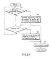
- An object of the present invention is to efficiently record/reproduce emergency information in a predetermined format.
- Another object is to inform a user of a fact that there has been an emergency broadcasting when the user turns on a power supply (and tries to watch TV), to thereby prevent the emergency broadcasting from being missed.
- an information recording medium which records a digital stream signal of a digital broadcasting system capable of broadcasting an emergency broadcasting program, the medium comprises:
- an information recording apparatus which records information in an information recording medium in which a digital stream signal of a digital broadcasting system capable of broadcasting an emergency broadcasting program is recorded, the medium comprising a data area for recording the emergency broadcasting program, and a management area for recording management information of the emergency broadcasting program, the apparatus comprises:
- an information recording method which records information in an information recording medium in which a digital stream signal of a digital broadcasting system capable of broadcasting an emergency broadcasting program is recorded, the medium comprising a data area for recording the emergency broadcasting program, and a management area for recording management information of the emergency broadcasting program, the method comprises the steps of:
- an information reproducing apparatus which reproduces information from an information recording medium in which a digital stream signal of a digital broadcasting system capable of broadcasting an emergency broadcasting program is recorded, the medium comprising a data area for recording the emergency broadcasting program, and a management area for recording management information of the emergency broadcasting program, the apparatus comprises:
- an information reproducing method which reproduces information from an information recording medium in which a digital stream signal of a digital broadcasting system capable of broadcasting an emergency broadcasting program is recorded, the medium comprising a data area for recording the emergency broadcasting program, and a management area for recording management information of the emergency broadcasting program, the'method comprises the steps of:
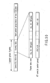
- FIGS. 1A to 1I are diagrams showing constitutions of an information recording medium, an information recording method, and an information reproducing method according to a first embodiment of the present invention.
- a transport stream which is a common basic format is divided into a management data part of a packet, and payload. In the payload, data of an object to be played back is included in a scrambled state.
- a program association table PAT which is one of digital broadcasting systems
- a program map table PMT which is one of digital broadcasting systems
- service information SI is not scrambled.
- PMT and SI SDT: service description table
- EIT event information table
- BAT bouquet association table
- Examples of a playback object of digitally broadcasted contents include MPEG video data, Dolby AC3(R) audio data, MPEG audio data, data broadcasting data and the like.
- the digital broadcasted contents also include information (program information, etc.) required for the playback, such as PAT, PMT, and SI, although they are not related to any direct playback object.
- PAT includes packet identification information PID of the PMT for each program. Furthermore, the PID of the video or audio data is recorded in the PMT.
- a set top box STB or the like there is the following usual playback procedure in a set top box STB or the like. That is, for example, when the user determines a program by electronic program guide EPG information, the PAT is read at a start time of the target program, the PID of the PMT belonging to.the desired program is determined based on the data, and the target PMT is read in accordance with the PID to determine the PID of a video or audio packet to be received, which is included in the PMT. Moreover, attributes of video and/or audio is read by the PMT or SI, and set into each decoder, and the video and/or audio data is cut out in accordance with the PID to perform the playback.
- the PAT, PMT, SI and the like are transmitted every several hundreds of milliseconds for use also during playback.
- stream recording has been proposed as a format for recording the stream as such, which is different from the existing video recording (VR) format.
- the existing stream recording SR
- the existing stream recording SR
- the SR is adapted for the stream recording of the digital broadcasting, while utilizing the existing VR resource.
- FIGS. 1A to 1I are explanatory views of a data structure according to one embodiment of the present invention.
- Examples of a disc-shaped information storage medium 100 include recordable optical disks such as DVD-RAM, DVD-RW, and DVD-R, and recordable magnetic disks such as a hard disk and the like.
- Optical disks such as DVD-RAM and the like will be described as the examples.
- the optical disk 100 has a lead-in area 110, a volume/file structure information area 111, a data area 112, and a lead-out area 113 from an inner peripheral side toward an outer peripheral side thereof (FIG. 1B).
- a file system is stored in the volume/file structure information area 111.
- the file system comprises information indicating a file and a place where the file is recorded. Recorded contents are stored in the data area 112 (FIG. 1C).
- the data area 112 is divided into a general computer information recording area 120 and an AV data recording area 121.
- the AV data recording area 121 comprises an AV data management information recording area 130 in which a file (VMG/ESMG file) for managing AV data is recorded, a VR object group recording area 122 in which an object data (VOBS) file (VRO file) of video recording specifications is recorded, and a stream object group recording area 131 in which a stream object set (SOBS) corresponding to the digital broadcasting is recorded (FIG. 1D). That is, in the embodiment, stream objects of the digital broadcasting are recorded as the stream object,set SOBS which is a file separate from a VR object (FIG. 1E).
- the SOBS comprises one or more stream objects (SOBs) 132.
- Each stream object (SOB) 132 comprises a set of one or more stream object units (SOBUs) 134 which are data units constituting access units to the disk 100.
- Each stream object unit (SOBU) 134 comprises a set of one or more packet groups (Packet_Groups) 140 comprising a set of a plurality of TS packets (FIG. 1G).
- Packet_Groups packet groups
- each packet group 140 comprises a set of eight logical blocks (LBs).
- LBs logical blocks
- a size of each packet group 140 is 16 Kbytes, and the group is recorded in the disk by this unit.
- Each packet group 140 constitutes a packet recording area (DVD-TS packet recording area) 160 in extended stream recording (ESR) provided by the present embodiment (FIG. 1H).
- the DVD-TS packet recording area 160 can comprise a packet group header 161, a plurality of (e.g., 85) MPEG-TS packets 162, and a plurality of (e.g., 84 pieces of) incremental packet arrival time information (IPAT) 163 (FIG. 1I).
- the contents of the packet group 140 will be described later with reference to FIG. 21.
- DVD-Video (ROM Video) has a directory VIDEO-TS
- DVD-RTR reproducing/reproducing DVD
- the directories are separated for each format in this manner.
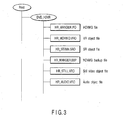
- information is recorded in a directory referred to as DVD_HDVR. That is, as shown in FIG. 3, in the directory referred to as the DVD_HDVR, a video manager (VMG) file (HDVMG) for managing the data, a video recording object file (VRO) which is an object file for analog recording such as analog broadcasting and line-in, and a stream recording object file (SRO) which is an object of the digital broadcasting are recorded.
- the SRO file is configured as a stream object set (SOBS).
- management data is recorded a VMG file common to the VR, the data is controlled in common with the VR, and linked by a cell unit, and a playback place is designated by a playback time unit.
- FIG. 2 is an explanatory view of a relation among a presentation control information layer 10, a stream object control information layer 20, and a stream object layer 30 in a data structure according to one embodiment of the present invention.
- the management information (VMG/ESMG file) recorded on the AV data management information recording area 130 of FIG. 1D has the presentation control information layer 10 to manage playback procedures of both recording contents based on video recording specifications and stream recording contents based on the present embodiment.
- one or more cells 13 which are playback units of a stream-recorded object constitute a program 12 together
- one or more cells 13* which are playback units of a video-recorded object constitute a program 12* together
- arrangement (playback procedure) of these programs 12, 12* is managed by management information (EX_PGCI) of a program chain (EX_PGC) 11.
- a user can designate a playback place by a playback time (PTS).
- PTS playback time
- the stream object (SOB) 132 in the stream object layer 30 is designated via stream object information (SOBI) 21 in the stream object control information layer 20.
- the stream object unit (SOBU) 134 in the stream object layer 30 is designated via stream object unit entry information (SOBUI_ENT) 22 in the stream object control information layer 20.
- SOBUI_ENT stream object unit entry information 22
- the playback start place is specified.
- the stream object unit entry information (SOBU_ENT) 22 may be referred to as global information 22.
- the stream object unit (SOBU) 134 comprises one or more packet groups 140.
- the stream object unit (SOBU) 134 corresponds to, for example, one or two GOPs, or is a unit from a head of an i-th I picture to a head of an (i+n)-th I picture (n is an integer). Additionally, when a breakpoint of the GOP is not found, the stream object unit (SOBU) 134 is divided by a unit corresponding to a data amount for one second (playback time) at maximum. Accordingly, overflow of each information field is prevented.
- Each packet group 140 comprises 8 LBs (16,384 bytes), the head thereof has a packet group header 161, and thereafter a plurality of transport stream packets (TS_Packets) 162, and a plurality of pieces of incremental packet arrival time information (IPATs) 163.
- TS_Packets transport stream packets
- IPTTs incremental packet arrival time information
- a video object (VOB) 36 in a video object layer 35 is designated via video object information (VOBI) 24 in a video object (VOB) management information layer 23.
- a video object unit (VOBU) 37 in the video object layer 35 is designated via video object unit entry information (VOBUI_ENT) 25 in the video object management information layer 23.
- VOBUI_ENT video object unit entry information
- the video object unit (VOBU) 37 comprises a plurality of packs 38, and the recording contents of the video recording are stored in these packs.
- the playback start place can be designated at the time of a field number unit by SOBU_PB_TM (FIG. 18).
- the playback start place can be designated by VOBU_PB_TM (not shown) in time map information (TMAPI) defined by the video recording. standard.
- the management data (EX_PGCI) of the stream recording can be recorded in the file common to that of the video recording, the stream recording and the video recording can be controlled in common, the stream recording can be linked with the video recording by the cell unit, and the playback place in the stream recording or the video recording can be designated by the playback time unit.
- a recording method is the stream recording or the video recording (VR)
- demands for special playback that the playback be started at a desired time (time search) and that fast feed (FF)/fast reverse (FR) be performed are frequently generated in the program desired by the user.
- FF fast feed
- FR fast reverse
- the object of the digital broadcasting is recorded as the stream of the stream object set (SOBS) 132 of the file which is separate from that of the VR object.
- management data of the stream object set (SOBS) is recorded in a VMG file common to a VR file, controlled in common with the VR, and linked by the cell unit, and the playback place is designated by the playback time unit.
- the structure of the stream object set comprises one or more stream objects (SOBS) 132, and the stream object (SOB) 132 corresponds, for example, to one program.
- the stream object (SOB) 132 comprises one or more stream object units (SOBUs) 134, and the stream object unit (SOBU) 134 corresponds to object data for one second, one or two Gap data, or one or more I pictures. Additionally, when a transfer rate is low, a case where one GOP is not sent within 1 second is considered (in the video recording VR, since internal encoding is performed, the stream object unit can be freely set, but the encoding is performed by a broadcasting station in the digital broadcasting, and therefore there is a possibility that the data is not known).
- the stream object unit (SOBU) 134 is frequently divided, accordingly the management information of the stream object unit (SOBU) 134 increases, and there is a possibility that the whole management information is enlarged.
- the stream object unit (SOBU) 134 is appropriately set apart, for example, by 0.4 seconds to 1 second (minimum limit of 0.4 seconds is applied to a unit opposite to the last stream object unit (SOBU) 134 of the stream object (SOB) 132), one GOP, or one or more I pictures.
- the packet group 140 comprises the packet group header 161, (85) TS packets 162, and (84) incremental packet arrival times (IPAT) 163.
- the arrival time of each TS packet is represented by an arrival time stamp (ATS) 152 in a packet group header, and the incremental packet arrival time IPAT (three or four bytes) 163. arranged before each TS packet 162, and the arrival time of the first TS packet in the packet group is represented by the arrival time stamp (ATS) 152 in the packet group.
- the arrival time of the next TS packet is represented by a value obtained by adding up the ATS 152 and the incremental packet arrival time (IPAT) 163 of the next TS packet.
- each of the arrival times of the next packets is represented by a value obtained by adding the incremental packet arrival time information (IPAT) 163 of each TS packet to the previous arrival time (ATS) 152.
- the arrival times of second and subsequent TS packets are represented by accumulation of the incremental packet arrival times (IPAT) 163 of the respective TS packets, which are one type of difference information.
- the incremental arrival time (IPAT) 163 of each TS packet is represented by a comparatively small data amount (three or four bytes), and a total data amount can be saved (as compared with a case where the arrival times of all the TS packets are represented by the arrival time (ATS) 152.
- a maximum transfer rate (described in a digital copy descriptor in the program map table PMT) of the digital broadcasting is checked, the rate needs to be set for each stream object SOB in accordance with the value, but a minimum rate cannot be determined. Therefore, the data comes late, and the rate cannot be represented by the I program association table (IPAT) 163 in some case.
- the packet group is ended (dummy data is input into vacancy), and the group shifts to the next packet group.
- a packet group header 161 comprises a synchronous pattern 151 set to the head of the pattern group, the arrival time information (ATS) 152 of the TS packet, and manufacturer's information (MNI) 153.
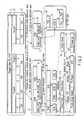
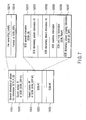
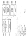
- FIG. 4 is an explanatory view of an example of constitution of HDVR_VMG which is one piece of the management information recorded in the AV data management information recording area 130 shown in FIG. 1D.
- the stream recording is abbreviated as the SR
- the video recording is abbreviated as the VR.
- the management information of the data of the SR is stored in the HDVR_VMG 130, and managed as the same rank as that of the VR data.
- the HDVR_VMG 130 comprises video manager information (HDVR_VMGI) 1310, a stream file information table (STR_FIT) 1320, (original) program chain information (ORG_EX_PGCI) 1330, play list information (PL_SRPT; or user defined program chain information table: UO_EX_PGCIT) 1340, a text manager (EX_TXTD_MG) 1350, and a manufacturer's information table (EX_MNFIT) 1360.
- video manager information (HDVR_VMGI) 1310
- STR_FIT stream file information table
- ORG_EX_PGCI original program chain information
- PL_SRPT play list information
- UO_EX_PGCIT user defined program chain information table
- EX_TXTD_MG text manager
- EX_MNFIT manufacturer's information table
- the play list and the user defined program chain have different names, but have substantially equivalent meaning, and are synonymous with the play list and the user defined program chain used in the video recording specifications. Therefore, in the following description, both information (PL_SRP, etc.) associated with the play list and information (UD_EX_PGCIT_SRP, etc.) associated with the user defined program chain are appropriately described.
- the HDVR_VMGI 1310 comprises disk management identification information (VMG_ID/ESMG_ID) 1311, version number of DVD video specifications (VERN) 1312, a start address of stream object control information (SFIT_SA) 1313, a start address of program chain information (ORG_EX_PGCI_SA) 1315, and a start address of play list information (UD_EX_PGCIT_SA) 1316.
- the management information of the stream is stored in a stream file information table (STR_FIT) 1320.
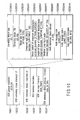
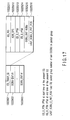
- FIG. 5 is an explanatory view of an example of constitution of the stream file information table (STR_FIT) 1320 of FIG. 4.
- the stream file information table (STR_FIT) 1320 comprises stream file information table information (STR_FITI) 1321, and one or more pieces of stream file information (STR_FI #1 to STR_FI #n) 1322.
- the stream file information table information (STR_FITI) 1321 comprises the total number of stream file information (STR_FI) 13211 and an end address of the present table (STR_FIT) 13212.
- the stream file information (STR_FI) 1322 comprises stream file information general information (STR_FI_GI) 13221, one or more stream object information search pointers (SOBI_SRP) 13222, and stream object information (SOB information: SOBI) 13223 arranged as many as the search pointers SRPs and indicated by a value indicating the number of the pointers.
- the general information (STR_FI_GI) of stream file information 13221 comprises a file name 13221 of an object file in which the SR object is stored, and the number 132212 of SOBI_SRP.
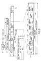
- the stream object information (SOBI) 13223 comprises stream object information general information (SOBI_GI) 132231, stream object elementary stream information 132232, stream object seamless information 132233, stream object time map information (SOB_TMAPI) 132236, and stream object elementary stream grouping information 132337.
- the stream object information general information (SOBI_GI) 132231 comprises a stream object type (SOB_TY) 13222101, a packet type (PKT_TY) 13222102, a packet size (PKT_SZ) 13222103, a packet group size (PKT_GRP_SZ) 13222104, the number (PKT_Ns) 13222105 of packets of a packet group, a country code (COUNTRY_CODE) 13222106, an application format name (AP_FORMAT) 13222107, a service ID (SERVICE_ID) 13243108, a service type (SERVICE_TYPE) 13243109, PID (PMT-PID) 13243110 of PMT packet, an original network ID (NETWORK_ID) 13243111, a transport stream ID (TS_ID) 13243112, PID of PCR packet (PCR_PID) 13243113, default PID (SOB_DEF_PID) 13243114 of the present stream object, an ID (FORMAT
- 0xff is set to the packet type PKT_TY, and 1 is set in the case of MPEG-TS.
- TMAPI introduced in the present embodiment is prepared, and playback or the like is performed.
- 0xff original management information inherent in a manufacture is held, and the contents are managed.
- the packet group size PKT_GRP_SZ is fixed at eight logical blocks (LB).
- the number PKT_Ns of the packets of the packet group is the number of the packets of 1PKT_GPP, and is fixed at 0x55:85TS packets.
- JPN Japan.
- AP_FORMAT 1 indicates ISDB-S: BS/CS broadcasting
- SOB_ES_Ns (the number of ESs selected for the recording), SOB_V_ES_Ns (the total number of the recorded video ESs), SOB_A_ES_Ns (the total number of the recorded audio ESs), PCR_POS_COUNT (the number of the PCR to be referred to, indicating the number of PCRs before the head of the packet group), PCR_POS_SHIFT (index part of 2 of LB indicating the position of the PCR packet), CP_CTRL_INFO, and the emergency flag (0: usual broadcasting, 1: emergency broadcasting) are recorded.
- the SOB_DEF_PID is the PID of default. In the ARIB system, a small value of a component tag is selected. Additionally, the value of the component group descriptor is given priority.
- the SOB_ESI 132232 on the video elementary stream comprises an elementary stream type (ES_TY) 13223201V, an elementary stream PID (ES_PID) 13223202V, a stream type (STREAM_TYPE) 13223203V indicated in the PMT, a value (COMPONENT_TAG) 13223204V of the component tag indicated by a stream identification descriptor, a stream contents value (STREAM_CONTENT) 13223205V indicated by the component descriptor, a component type value (COMPONENT_TYPE) 13223206V indicated by the component descriptor, a video elementary stream attribute (V_ATR) 13223207V, . and copy control information (CP_CTRL_INFO) 13223208V.
- the video attribute V_ATR is of two bytes, and b9, b8 are an application flag (00b: the present video stream is coded at an aspect ratio designated by the present V_ATR, 01b: the present video stream is coded at an aspect ratio designated by the present V_ATR, an actual aspect ratio is not recorded in the stream, and the others are reserved).
- b7 indicates a line-21 switch (1b: user data with respect to data of Line 21 of Field 1 is recorded in the GOP layer, 0b: user data with respect to the data of Line 21 of Field 1 is not recorded in the GOP layer).
- b6 indicates a second line-21 switch (1b: the user data with respect to the data of Line 21 of Field 1 is recorded in the GOP layer, 0b: the user data with respect to the data of Line 21 of Field 1 is not recorded in the GOP layer).
- b5 to b2 indicate a horizontal resolution (0000b: 1,920 lines, 0001b: 1,440 lines, 0010b: 1,280 lines, 0011b: 720 lines, 0100b: 544 lines, 0101b: 480 lines), and the others are reserved.
- the copy control information (CP_CTRL_INFO) 13223208V is of two bytes, b15 and b14 indicate CCI (00b: copy free, 10b: no more copy, 10b: copy one generation, 11b: copy never), and b13 and b12 indicate APS (00b: copy free, 01b: APS of Type 1 (AGC) is on, 10b: APS of Type 2 (AGC + 2L color stripe) is on, 11b: APS of Type 3 (AGC + 4L color stripe) is on).
- b10 indicates an image construction token (ICT) (0b: HD image (high definition image) is converted into SD image (standard definition image), and analog output results, 1b: analog output of HD image as such).
- b6 to b4 indicate Retention_State (000b: non limitation, 001b: one week, 010b: two days, 011b: one day, 100b: 12 hours, 101b: six hours, 110b: three hours, 111b: 90 minutes), and the others are reserved.
- the APS indicates an analog protection system, and a macro vision is assumed in the present embodiment.
- the SOB_ESI 132232 on the audio elementary stream comprises an elementary stream type (ES_TY) 13223201A, a PID (ES_PID) 13223202A of the elementary stream, a stream type (STREAM_TYPE) 13223203A indicated in the PMT, a value (COMPONENT_TAG) 13223204A of the component tag indicated by a stream ID descriptor, a stream contents value (STREAM_CONTENT) 13223205A indicated by the component descriptor/audio component descriptor, a component type value (COMPONENT_TYPE) 13223206A indicated by the component descriptor/audio component descriptor, a simultaneous cast group tag (SIMULCAST_GP_TAG) (simultaneous cast group identification) 13223207A, an audio elementary stream attribute (A_ATR) 13223208A, a language code (LANG_CODE) 13223209A
- the audio attribute A_ATR is of one byte
- b7 indicates a multilingual flag (0b: non-multilingual stream
- 1b bilingual stream in a case where the stream is dual/mono)
- b6 indicates a main component flag (0b: not main
- 1b main audio
- b5 indicate.
- a quality indicator (00b: reserved, 01b: Mode 1, 10b: Mode 2, 11b: Mode 3)
- b3 to b1 store a sampling rate (011b: 24 kHz, 101b: 32 kHz, 111b: 48 kHz, the others are reserved)
- b0 is reserved:
- the LANG_CODE describes the language code of the first sound of the present stream
- the LANG_CODE2 describes the language code of the second sound in a case where the present stream is a multilingual stream.
- the copy control information CP_CTRL_INFO is of two bytes, and is the same as that shown in FIG. 15C.
- the SOB_ESI 132232 on the other elementary streams comprises an elementary stream type (ES_TY) 13223201D, an elementary stream PID (ES_PID) 13223202D, a stream type indicated in the PMT (STREAM_TYPE) 13223203D, a value of the component type indicated by a stream ID descriptor (COMPONENT_TAG) 13223204D, a stream contents value indicated by the component descriptor (STREAM_CONTENT) 13223205D, a component type value (COMPONENT_TYPE) 13223206D indicated by the component descriptor, and copy control information (CP_CTRL_INFO) 13223207D.
- ES_TY elementary stream type
- E_PID elementary stream PID
- STREAM_TYPE stream type indicated in the PMT
- STREAM_TYPE stream type indicated in the PMT
- COMPONENT_TAG stream ID descriptor
- STREAM_CONTENT a stream contents value indicated by the component descriptor
- CP_CTRL_INFO The copy control in formation CP_CTRL_INFO is of two bytes, and is the same as that shown in FIG. 15C.
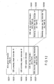
- the stream object time map information (SOB_TMAPI) 132236 comprises the stream object time map general information (SOB_TMAP_GI) 1322361, and elementary stream time map information (ES_TMAPI) 1322362.
- the stream object elementary stream grouping information (SOB_ES_GPI) 132337 comprises SOB_ES_GPI general information (SOB_ES_GPI_GI) 1323371, one or more ES_GPI search pointers (ES_GPI_SRP) 1323372, and one or more pieces of ES grouping information (ES_GPI) 1323372 indicated by the search pointer.
- SOB_ES_GPI general information SOB_ES_GPI_GI
- ES_GPI_SRP ES_GPI search pointers
- ES_GPI pieces of ES grouping information
- the SOB_ES_GPI 132337 corresponds to a multi-view broadcasting, and indicates a video and audio constituting a group and constituting a set at the time of the playback.
- GPI1 first GPI
- PID of the ES to be played back is set by a component group descriptor and a stream descriptor in the GPI.
- the ES grouping information (ES_GPI) 1323373 comprises ES grouping general information (ES_GPI_GI) 13233731, and ES_PID 13233732.
- the stream object time map general information (SOB_TMAP_GI) 1322361 comprises an address offset ADR_OFS (packet group number (LB address) from file head to SOB head) 13223611, SOBU_PB_TM_RNG (range of the playback time.of SOBU: 1: 0.4 to 1.2 seconds, 2: 1 to 2 seconds, 3: 2 to 3 seconds) 13223612, SOB_S_PKT_POS (start in the packet group of the head of the SOB: 1 ⁇ SOB_S_PKT_POS ⁇ 85) 13223613, SOB_E_PKT_POS (end in the packet group of the head of the SOB: 1 ⁇ SOB_E_PKT_POS ⁇ 85) 13223614, and ES_TMAP_Ns (the number of the time maps of the elementary stream) 13223615.
- ADR_OFS packet group number (LB address) from file head to SOB head) 13223611
- SOBU_PB_TM_RNG range of
- the SOB_TMAPI can be prevented from being excessively enlarged. Additionally, since a time interval of each entry extends, a possibility that the playback at a double speed cannot be smoothly performed increases.
- the elementary stream time map information (ES_TMAPI) 1322362 comprises elementary stream time map information general information (ES_TMAPI_GI) 13223621 and one or more stream object entries (SOBU_ENT) 13223622.
- the elementary stream time map information general information (ES_TMAPI_GI) 13223621 comprises an ES_packet identifier (ES_PID) 132225211, an address offset (ADR_OFS) 132225212, ES_S_PTM (PTM at the start time of the present elementary stream) 132225213, ES_E_PTM (PTM at the end time of the present ES) 132225214, the number (SOBU_ENT_NUMs) 132225215 of SOBU entries, and LAST_SOBU_E_PKT_POS (last TS packet group number of the last ESOBU in the packet group) 132225216.
- E_PID ES_packet identifier
- ADR_OFS address offset
- ES_S_PTM PTM at the start time of the present elementary stream
- ES_E_PTM PTM at the end time of the present ES
- LAST_SOBU_E_PKT_POS last TS packet group number of the last ESO
- the information comprises last address information (LB unit) (1st_ef_PIC_SZ) 132236221 from SOBU head of a first reference picture (I picture) in the entry, playback time (field number) of SOBU (SOBU_PB_TM) 132236222, a SOBU size (SOBU_SZ) 132236224 (packet group number, the number of the packet groups belonging to the SOBU), SOBU_S_PKT_POS 132236225 (packet number from the head of the packet group including the head of the SOBU), and PCR_POS 132236226 (indicating the position of the PCR in a position represented by PCR_POS_COUNT).
- LB unit last address information
- the PCR_POS is the position of the PCR in the position indicated by PCR_POS_COUNT by an address number from the SOBU head. If the information does not exist, 0xffff is indicated.
- the LB number is indicated by PCR_POS x 2 PCR_POS_SHIFT .
- the PCR indicates a position before a position where there is a reference picture, and the position of the PCR several minutes before, indicated by a PCR interval.
- the SOBU of the target time is obtained by accumulation of PB_TM, and the playback start PTM is-converted by the field number from the head of the SOBU.
- the target SOBU is K
- a target address is A
- the packet of the head is a packet indicating a value of SOBU_S_PKT_POS, and this address is accessed.
- the information comprises last address information (the same as above) from the SOBU head of the first sound frame in the entry, the playback time (field number) of the SOBU, the size (the same as above) of the SOBU, and PCR_POS.
- the entry information since the entry information is not configured, the information is all filled with FF.
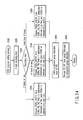
- the playback information is EX_PGC information
- the format is the same as a usual VR format
- original program chain information ORG_EX_PGC is automatically prepared by the apparatus at the time of the recording, and the information is set in a recording order.
- User defined program chain information UD_EX_PGC is prepared following a playback order freely added by the user, and called a play list.
- These two formats have a common EX_PGC level, and the EX_PGC format is shown in FIG. 19.
- Program chain information 1330 comprises original program chain information (ORG_EX_PGC) 1331..
- Play list information 1340 comprises program chain table information (UD_EX_PGCT) 1341, one or more program chain (UD_EX_PGC) search pointers 1342, and one or more pieces of program chain information (UD_EX_PGC Info) 1343.
- U_EX_PGCT program chain table information
- U_EX_PGC program chain search pointers
- U_EX_PGC Info pieces of program chain information
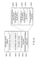
- the program chain information comprises program chain general information (EX_PGC_GI) 1331, one or more pieces of program information (EX_PGI) 1332, one or more cell search pointers (EX_CELL_SRP #1 to EX_CELL_SRP #q) 1333, and one or more pieces of cell information (EX_CI #1 to EX_CI #q) 1334.
- EX_PGC_GI program chain general information
- EX_PGI program chain general information
- EX_PGI program chain general information
- EX_PGI program chain general information
- EX_PGI program information
- cell search pointers EX_CELL_SRP #1 to EX_CELL_SRP #q
- EX_CI #1 to EX_CI #q EX_CI #1 to EX_CI #q
- the program chain general information (EX_PGC_GI) 1331 comprises a program number 13311, and cell search pointer number (CELL_SRP number) 13312.
- the program information (EX_PGI) 1332 comprises a program type 13321, an in-program cell number 13322, PRIM_TXT information 13323, an IT_TXT_SRP number 13324, representative_PIC information 13325, an editor ID 13326, a program index number (PG absolute number) 11327, a program update date 13328, and a manufacturer's information (MNFI) number 13329.
- Information of date/time when the program has been updated is stored in the program update date. Accordingly, a time when the present program has been edited is seen.
- the PRIM_TXT information 13323 is used for a program name, another information (a director name, a leading actor name, ...) is stored in the IT_TXT area 1350 in order to store the other text information, the stored IT_TXT SRP number 13324 is set to the EX_PGI 1332, and the information is linked. Furthermore, the PG index number 13327 is also set to the IT_TXT data 1350.
- the PG index number 13327 is an absolute number from when the recording is started with respect to an index, and is an index number which is unchanged even when the other PG is deleted.
- the SRP number 13329 of the MNFI is set to the EX_PGI 1332 in order to use the MNFI information arranged in order to realize a function unique to the manufacture. Furthermore, even in the MNFI information, the data in the MNFI information is linked by setting a PG number (not shown).
- update date information is also set to both the MNFI and IT_TXT, agreement of the time is checked at the time of menu display, and it is accordingly verified whether or not edition has been performed by another manufacture.
- the cell information (EX_CI) 1334 comprises a cell type 13341, an STI_FI number 13342, a corresponding SOB number 13343, a referred ID 13344, C_EPI_Ns 13345, cell start PTS/ATS 13345, cell end PTS/ATS 13347, and CP_EPI 13348.
- the cell type 13341 indicates the type of the SOB, and designates the SOB number 13343, start time 13346, and end time 13347.
- the start time and end time are' represented by two types: a PTS unit (playback time), and an ATS unit (transfer time).
- the playback time (actual time of the playback) is designated in-time designation
- the same access method as that of the conventional VR is possible, the user designates the playback time, and therefore user's desire is completely reflected.
- the designation is possible in a case where contents of the stream can be sufficiently analyzed. In a case where the contents are not sufficiently seen, the time has to be designated by a transfer time unit.
- the playback cannot be necessarily started at the head of the I picture.
- the decoding is started from the I picture immediately before the frame.
- the display is started, and it is displayed to the user as if the playback were started from the designated frame.
- a method of setting a packet identifier PID (or a value of the component tag) of a stream representing the stream to be played back, and a method of setting the ID of the component group in the case of multi-view TV or the like are considered.
- a method of performing multi-display in a sub-screen, and a method of preferentially displaying a group set in advance (or a main group of default) and switching the display later (during the playback) are considered.
- Peculiar ID numbers may be attached to PG and CELL, and the PG and CELL may be designated with numbers which do not change even if middle PG and CELL are deleted.
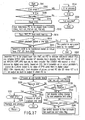
- FIG. 21 is an explanatory view of one example of constitution of the data unit (SOBU) 134 for the stream object shown in FIG. 1F or 2.
- SOBU data unit
- One SOBU 134 comprises one or more packet groups 140, and each packet group 140 comprises, for example, eight packs.
- Each packet group 140 comprises a packet group header (152 bytes) 161, one or more (85 herein) MPEG-TS packets (188 bytes) 162, and one or more (84 herein) incremental packet arrival times (IPAT, three or four bytes) 163.
- the packet group header 161 comprises a synchronous pattern 151 (00FFA5A5), a packet arrival time (ATS) 152, and manufacturer's information (MNI) 153. It is to be noted that the packet group header 161 may further include presentation time stamp (PTS).
- PTS presentation time stamp
- each MPEG-TS packet 162 comprises a four-byte header 170, and an adaptation field and/or payload 180.
- the header 170 comprises a synchronous byte 171, transport error indicator 172, payload unit start indicator 173, transport priority 174, packet identifier (PID) 175, transport scramble control 176, adaptation field control 177, and continuity index 178.
- PID packet identifier
- a TS stream (FIG. 21) which is a common basic format is divided into the management data part (170) and the payload (180) of the packet.
- a program association table PMT or service information SI is not scrambled. It is possible to prepare various management information using the PMT or SI (service description table, event information table, bouquet association table).
- MPEG video data As playback objects, there are MPEG video data, Dolby AC3(R) audio data, MPEG audio data, data broadcasting data and the like.
- information which is not directly related to the playback objects but which is necessary in the playback there are information (program information, etc.) such as PAT, PMT, and SI.
- the PAT includes packet identification (PID) of the PMT for each program, and the PID of the video data or the audio data is further recorded.
- PID packet identification
- STB set top box
- EPG electronic program guide
- the PAT is read at the start of a target program
- the PID of the PMT belonging to the desired program is determined based on the data.
- the target PMT is read in accordance with the PID
- the PID of the video or audio packet to be played back, included in the PMT is determined.
- an attribute of the video or audio is read by the PMT or SI, and set to each decoder, and the video or audio data is cut out in accordance with the PID, and played back.
- the PAT, PMT, SI and the like are used also during playback, they are transmitted every hundreds of milliseconds.
- the stream number to be recorded in the SOBI is held, the PMT corresponding to each stream is stored, map information (map group information) for special playback is held in each stream, and the number of the stream (the channel number or the PID of the PMT) to be played back may be recorded in the cell information.
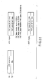
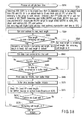
- FIG. 22 is an explanatory view of an example of constitution of the arrival time (ATS) 152 of the packet included in the packet group header shown in FIG. 21.
- ATS arrival time
- a PAT base e.g., a counter value of 90 kHz
- the 8 to 0 bits represent a PAT extent (e.g., a counter value of 27 MHz).
- An actual arrival time PAT is represented by PAT_base/90000 Hz + PAT_exten/27,000,000 Hz. Accordingly, the ATS 152 can be finely represented, for example, by a video frame unit.
- FIG. 22 also shows one example of constitution of an increment (IPAT) 163 of the packet arrival time, which is included in the packet group header in the packet group shown in FIG. 21.
- IPAT increment
- FIG. 22 also shows one example of constitution of an increment (IPAT) 163 of the packet arrival time, which is included in the packet group header in the packet group shown in FIG. 21.
- IPAT 163 may represent the increment (change) from the ATS 152, not the absolute time, a data amount of the IPAT is smaller than that of the ATS.
- the actual arrival time PAT in the IPAT 163 is represented by ATS + PAT_base/90000 Hz + PAT_exten/27,000,000 Hz. Accordingly, the IPAT 163 can be finely represented, for example, by the video frame unit. It is to be noted that as another mode, it is also possible to use a difference from the arrival time from the previous TS packet (to add PAT_base/90000 Hz + PAT_exten/27,000,000 Hz to the previous PAT to constitute a new PAT).
- PAT in the above-described "PAT_base and PAT_exten” means the "packet arrival time", not the "program association table”.
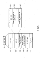
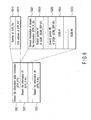
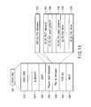
- FIG. 23 is a block diagram showing an example of an apparatus which records/plays back audio/video (AV) information (digital TV broadcasting program, etc.) in an information recording medium (optical disk, hard disk, etc.) utilizing a data structure according to one embodiment of the present invention.
- AV audio/video
- the apparatus comprises a main MPU unit 80, key input unit 103, remote controller receiver 103b which receives user operation information from a remote controller 103a, display unit 104, decoder unit 59, encoder unit 79, system time counter (STC) unit 102, data processor (D-PRO) unit 52, temporary storage unit 53, disk drive unit 51 which records/plays back information with respect to a recordable optical disk 100 such as a DVD-RAM, hard disk drive (HDD) 100a, video mixing (V-mixing) unit 66, frame memory unit 73, D/A converter 67 for analog TV, analog TV tuner unit 82, terrestrial digital tuner unit 89, set top box (STB) unit 83 connected to a satellite antenna 83a, terrestrial tuner unit 82, and emergency broadcasting detection unit 108 which is connected to the STB unit 83 and which sets power activation instruction and emergency broadcasting information with respect to the MPU unit 80, on detecting the emergency broadcasting.
- STC system time counter
- D-PRO data processor
- the STC unit 102 is configured to count clocks on a 27 MHz base in accordance with the PAT_exten of FIG. 17.
- the STB unit 83 decodes received digital broadcasting data to generate an AV signal (digital), and sends the AV signal to a TV monitor 68 via the encoder unit 79, decoder unit 59, and D/A converter 67 in the streamer, so that the contents of the received digital broadcasting can be displayed.
- the STB unit 83 is also configured to be capable of sending the decoded AV signal (digital) directly to the V-mixing unit 66 and sending an analog AV signal to the TV monitor 68 from the V-mixing unit 66 via the D/A converter 67.
- the apparatus of FIG. 23 constitutes a recorder comprising functions of both video recording and stream recording
- the apparatus comprises components (IEEE 1394 I/F, etc.) unnecessary in the video recording or components (an A/D converter 84 for AV input, audio encoder unit 86, video encoder unit 87, etc.) unnecessary in the stream recording.
- the encoder unit 79 comprises the A/D converter 84, video encoder unit 87, input switch selector 85 to the video encoder unit 87, audio encoder unit 86, sub-picture encoder unit (not shown, but if necessary), formatter unit 90, and buffer memory unit 91.
- the decoder unit 59 comprises a demultiplexer 60 which contains a memory 60a, video decode unit 61 which contains a memory 61a and a generator 62 of a reduced-scale picture (thumbnail, etc.), sub-picture (SP) decode unit 63, audio decode unit 64 which contains a memory 64a, TS packet transfer unit 101, video processor (V-PRO) unit 65, and D/A converter 70 for audio.
- An analog output (monaural, stereo, or AAC 5.1CH surround) from the D/A converter 70 is input into an AV amplifier and the like (not shown), and the necessary number of speakers 72 are driven.
- stream data to be recorded is sent to the D-PRO unit 52, simultaneously sent also to the decoder unit 59, and can be reproduced.
- the MPU unit 80 sets the decoder unit 59 at the time of playback, and thereafter the decoder unit 59 automatically performs a playback process.
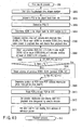
- the D-PRO unit 52 forms an ECC group, for example, every 16 packs, attaches an ECC, and sends the data to the drive unit 51. Additionally, when the drive unit 51 is not prepared for the recording into the disk 100, the data is transferred to the temporary storage unit 53. The apparatus waits until preparations for recording the data are made. In a stage in which'the preparations are made, the recording is started. Here, since the temporary storage unit 53 holds the recording data for several minutes or more at a high-speed access, a large-capacity memory is assumed. This temporary storage unit 53 can be configured utilizing a part of the HDD 100a.
- the MPU unit 80 is configured in such a manner as to be capable of reading/writing the data with respect to the D-PRO unit 52 through a microcomputer bus for exclusive use in order to read/write the data with respect to a management area of a file or the like.
- the optical disk 100 for example, DVD-RAM/-RW/-R/Blue media (recordable media using blue laser) or the like, is assumed as a recording medium, and the hard disk drive (HDD) 100a (and/or a large-capacity memory card (not shown), etc.) is assumed as an auxiliary storage device.
- the hard disk drive (HDD) 100a and/or a large-capacity memory card (not shown), etc.
- a way of using these plurality of mediums is, for example, as follows. That is, the stream recording is performed with respect to the HDD 100a utilizing the data structure (format) of FIGS. 1 to 22. Moreover, in the stream recording contents recorded in the HDD 100a, the program desired to be stored by the user is subjected to the stream recording (direct copying or digital dubbing) as such in the disk 100 (in a case where the copying is not prohibited by the copy control information CCI). In this case, only desired program having a quality equivalent to an original quality of the digital broadcasting can be recorded in the disk 100. Furthermore, since the data structure of the present embodiment is utilized in the stream recording contents copied to the disk 100, special playback such as time search (described later with reference to FIG. 40) is facilitated even in the stream recording.
- a concrete example of a digital recorder (streamer/video recorder comprising a combination of DVD-RAM/-RW/-R/Blue media with the HDD) having the above-described characteristics is the apparatus of FIG. 23.
- the digital recorder of FIG. 23 roughly comprises the tuner unit 82, 83, 89, disk unit 100, 100a, encoder unit 79, decoder unit 59, and control unit 80.
- Satellite digital TV broadcasting is broadcasted from a broadcasting station through a communication satellite.
- the broadcasted digital data is received and reproduced by the STB unit 83.
- the STB unit 83 is a unit which extends and reproduces the scrambled data based on a key code supplied from the broadcasting station. At this time, the scrambling from the broadcasting station is descrambled.
- the data is scrambled in order to prevent the broadcasted program from being illegally heard/seen by a user who does not contract reception with respect to the broadcasting station.
- the broadcasted digital data is received by a tuner system (not shown).
- the scrambling is descrambled by a digital extension unit
- the received data is decoded by an MPEG decoder unit
- the data is converted into a TV signal by a video encoder unit
- the TV signal is sent to the outside via the D/A converter 67. Accordingly, the digital broadcasting program received by the STB unit 83 can be displayed by the analog TV monitor 68.
- Terrestrial digital broadcasting is received and processed in the same manner as in the satellite broadcasting except that the broadcasting does not go through the communication satellite (and the data is not be scrambled in free broadcasting). That is, the terrestrial digital broadcasting is received by the terrestrial digital tuner unit 89. When the broadcasting is reproduced as such, the decoded TV signal is sent to the outside via the D/A converter 67. Accordingly, the digital broadcasting'program received by the terrestrial digital tuner unit 89 can be displayed by the analog TV monitor 68.
- the terrestrial digital tuner unit 89 and the STB unit 83 supplies command/error information to a system bus (MPU unit 80).
- the terrestrial analog broadcasting is received by the terrestrial tuner unit 82.
- the received analog TV signal is sent to the outside. Accordingly, the analog broadcasting program received by the terrestrial tuner unit 82 can be displayed by the TV monitor 68.
- An analog video signal analog-input from an external AV input 81 can be sent straight to the TV monitor 68, but may be once A/D converted by the A/D converter 84, thereafter returned to the analog video signal by the D/A converter 67, and sent to an external TV monitor 68.
- the (digital time base collected) analog video signal that does not have any jitter can be output on the side of the TV monitor 68.
- the digital video signal digital-input from the digital I/F (IEEE 1394 interface) 74 is sent to the external TV monitor 68. Accordingly, the digital video signal input in the digital I/F 74 can be displayed in the TV monitor 68.
- the satellite digital broadcasting, terrestrial digital broadcasting, or a bit stream (MPEG-TS) input from the digital I/F 74 can be stream-recorded as the stream object 132 of FIG. 1E in the stream object group recording area 131 (FIG. 1D) of the disk 100 (and/or the HDD 100a).
- MPEG-TS bit stream
- the terrestrial analog broadcasting or the analog video signal from the AV input 81 can be video-recorded in the VR object group recording area 122 (FIG. 1D) of the disk 100 (and/or the HDD 100a).
- the apparatus can be configured in such a manner that the terrestrial analog broadcasting or the analog video signal from the AV input 81 is once A/D converted, and the stream recording is performed, not the video recording.
- the apparatus may be configured in such a manner that the satellite digital broadcasting, the terrestrial digital broadcasting, or the bit stream (MPEG-TS) input from the digital I/F 74 is subjected to the video recording, not the stream recording (after necessary format conversion is performed).
- MPEG-TS bit stream
- the MPU unit 80 has a management data generator 80B of the stream recording and video recording, prepares various management information using a work RAM 80A as a work area, and appropriately records the prepared management information in the AV data management information recording area 130 of FIG. 1D.
- the MPU unit 80 reproduces the management information recorded in the AV data management information recording area 130, and performs various controls (FIGS. 24 to 43) based on the reproduced management information. It is to be noted that manufacture ID information or the like of the apparatus of FIG. 23 can be written beforehand in the ROM 80C of the MPU unit 80.
- the medium comprises a management area 130 and a data area 131.
- the data is separated into a plurality of object data (stream objects (SQBs)) and recorded in the data area, and each object data comprises a set of data units (SOBUs).
- one data unit (SOBU) comprises pack groups obtained by pack-grouping digital broadcasting signals for each TS packet, conforming to the MPEG-TS, by a plurality of packs (see FIGS. 1F, 21).
- the management area 130 comprises EX_PGC information (EX_PGCI) as information which manages the playback procedure, and the EX_PGC information (EX_PGCI) comprises cell information (CI). Furthermore, the management area 130 has information which manages the object data (stream object (SOB)).
- EX_PGC information EX_PGCI
- EX_PGCI EX_PGC information
- CI cell information
- the management area 130 has information which manages the object data (stream object (SOB)).
- the apparatus of FIG. 23 can perform the stream recording in addition to the video recording with respect to the medium 100 (100a) having the above-described data structure.
- the MPU unit 80 is configured in such a manner as to have a service information fetching section (not shown, firmware constituting a part of the management data generator 80B).
- the MPU unit 80 is also configured in such a manner as to have an attribute information generator (not shown, firmware constituting a part of the management data generator 80B) which prepares attribute information (PCR_LB number, etc.) based on the information taken by the service information fetching section.
- the signals at the time of the recording flow, for example, as follows.
- the TS packet data received by the STB unit 83 (or the terrestrial digital tuner unit 89) is packet-grouped by the formatter unit 90, and stored into a work area (buffer memory unit 91).
- a certain amount of data is stored (in a stage in which the data for one or integer times CDA is stored)
- the data is recorded in the disk 100.
- the packets are grouped every 85 packets, and a packet group header is prepared.
- the analog signal input via the terrestrial tuner unit 82 or a line input is digital-converted by the A/D converter 84.
- the digital signal is input into the respective encoder unit 86, 87.
- the video signal is input into the video encoder unit 87, the audio signal is input into the audio encoder unit 86, character data such as character broadcasting is input into an SP encoder unit (not shown), the video signal is MPEG-compressed, the audio signal is subjected to AC3 compression or MPEG audio compression, and the character data is subjected to run-length compression.
- each packet is formed into the block, further multiplexed, and sent to the D-PRO unit 52.
- the D-PRO unit 52 prepares an ECC block every 16 (or 32) blocks, attaches error correction data, and records the data in the disk-100 by the disk drive unit 51.
- the drive unit 51 in a case where the drive unit 51 is seeking the data or jumps to another track, the data is input into the HDD buffer unit 53 in a busy state, and the apparatus waits until the preparations of the RAM drive unit 51 are made. Furthermore, the drive unit 51 prepares each delimitation information during the recording, and periodically sends the information to the MPU unit 80 (GOP head interruption, etc.). As the delimitation information, there are the LB number of the VOBU (SOBU), end address of the I picture from the VOBU (SOBU) head, playback time of VOBU (SOBU) and the like.
- SOBU LB number of the VOBU
- SOBU end address of the I picture from the VOBU
- SOBU playback time of VOBU
- the data is read from the disk 100 by the drive unit 51, errors are corrected by the D-PRO unit 52, and the data is input into the decode units 61, 63, 64.
- the MPU unit 80 determines whether the type of the input data is VR data or ESR data (determined by Cell TYPE), and sets the type to the decoder unit before playback. In the case of the ESR data, the MPU unit 80 determines PMT_ID to be played back from cell information CI to be played back, determines the PID of each item (video, audio, etc.) to be played back from the corresponding PMT, and sets the PID to the decoder unit.
- the decoder unit sends each TS packet by the demultiplexer 60 to each decoder unit based on the PID. Furthermore, the data is sent to the TS packet transfer unit 101, and transmitted to the STB unit 83 (1394 I/F 74) in the form of the TS packet in accordance with the arrival time. Each decoder unit performs the decoding, and the data is converted into the analog signal by'the D/A converter 67, and displayed in the TV monitor 68.
- the demultiplexer 60 sends the data to each decoder unit in accordance with the fixed ID.
- Each decoder unit performs the decoding, and the data is converted into the analog signal by the D/A converter 67, and displayed in the TV monitor 68.
- FIG. 24 is a flowchart showing an operation at a main power-off time (standby time). Even when a main power is off, power is supplied to the terrestrial digital tuner unit 89, MPU unit 80, timer unit, and display unit 104.
- the emergency broadcasting detection unit 108 On receiving the emergency broadcasting at step S12, the emergency broadcasting detection unit 108 gives a power activation instruction to the MPU unit 80, determines at step S14 the program (emergency broadcasting) being received as a program to be recorded, and sets an emergency broadcasting flag to the SOB_GI (FIG. 8).
- a power activation process is performed at step S16, and the process advances to a usual process (FIG. 25).
- step S12 digital broadcasting data is taken in, an emergency information descriptor in the program map table PMT is found, and emergency information Start_End_Flag in the descriptor is checked. When the flag is 1, it is determined that the emergency broadcasting has been received. An emergency level is also found by service information Signal_Level.
- step S18 When the emergency broadcasting is not received at step S12, it is determined at step S18 whether or not it is a reserved time. At the reserved time, the reserved program is determined as the program to be recorded at step S20. After setting a reserved recording flag, a power activation process is performed at step S16, and the process advances to a usual process (FIG. 25).
- FIG. 25 is a flowchart showing an example of an operation of the usual process.
- theMPU unit 80 performs initial setting (at the time of factory shipping or after user's setting) (step S22), performs display setting (step S24), and determines whether or not the emergency broadcasting flag and reserved recording flag have been set (step S26).
- step S22 the initial setting
- step S24 the display setting
- step S26 determines whether or not the emergency broadcasting flag and reserved recording flag have been set
- step S28 determines whether or not the emergency broadcasting flag and reserved recording flag have been set.
- step S30 it is determined at step S30 whether or not the emergency recorded flag is set.
- the emergency recorded flag is set, an emergency broadcasting display process is performed at step S32.
- step S34 When the emergency recorded flag is not set, a user's key operation is waited for at step S34.
- the MPU unit 80 interprets contents of the key input (step S36). The following seven data processes are appropriately executed in accordance with results of the input key interpretation.
- a menu process is performed at step S38. Thereafter, the process returns to step S34 in which the key input is waited for.
- the program setting process is performed at step S40.
- a recording process is performed at step S42.
- the flag is set
- the emergency recorded flag is set at step S54, and the process returns to a standby process.
- the process returns to step S34 to wait for a next key input.
- a playback process is performed at step S44. Thereafter, the process returns to step S34 to wait for a next key input.
- a digital output process is performed at step S46, and thereafter the process returns to step S34 to wait for a next key input.
- the key input is a key operation of an edition process
- the edition process is performed at step S48, and thereafter the process returns to step S34 to wait for a next key input.
- the key input is a key operation for a time search process
- the time search process is performed at step S50, and thereafter the process advances to a playback process (step S44).
- steps S38, S40, S42, S44, S46, S48, S50 are appropriately processed in parallel for each task.
- a process (S46) of the digital output to the STB unit 83 is executed in parallel during the playback process (S44).
- a new program setting process (S40) can be configured to be carried out in parallel during the recording process (S42) which is not timer reserved recording.
- the playback process (S44) and digital output process (S46) can be configured to be processed in parallel during the recording process (S42) utilizing characteristics of the recording of the disk accessible at a high speed. It is also possible to perform an edition process (S48) of the disk during the recording into the HDD 100a.
- FIG. 26 is a flowchart (edition operation process flow) showing one example of contents of the edition process (S48) shown in FIG. 25.
- the flow can enter one of four processes (S64, S66, S68, S70) in accordance with edition contents (step S62).
- a program update date (EX_PGI, EX_IT_TXT, EX_MNFI) is set. It is to be noted that one of EX_PGI, EX_CI, and VOB is set at a changing time.
- FIG. 27 is a flowchart showing details of the emergency broadcasting program detection process (S12) of FIG. 24.
- the TS packet is taken in, and the PID is checked. It is determined at step S84 whether or not there is a program map table (PMT). When there is the PMT, the PMT is read at step S86, and a table is constructed inside. It is determined at step S88 whether or not there is an emergency information descriptor. When there is the descriptor, it is determined at step S90 whether or not an emergency information Start_End_Flag is 1. When the flag is 1, an event information table (EIT) is read at step S92, and a table is constructed inside. At step S94, service_ID, recording start time, recording time, title and the like are set. At step S96, it is informed that the emergency broadcasting has entered the MPU unit 80, and the emergency broadcasting information is sent to the MPU unit 80.
- PMT program map table
- FIGS. 28A and 28B show a flowchart (recording flow) showing one example of a recording operation of the apparatus of FIG. 23.
- the program to be recorded is determined beforehand using an electronic program guide (EPG) in the program setting process (S40) of FIG. 25, the receiving is started, and the determined program is recorded.
- EPG electronic program guide
- the data is simultaneously sent to the decoder unit 59 and the D-PRO unit 52, and played back. Additionally, in this case, the MPU unit 80 performs the setting at the playback time with respect to the decoder unit 59, and thereafter the decoder unit 59 automatically plays back the data.
- the D-PRO unit 52 constitutes an ECC group every 16 packs, attaches the ECC, and sends the data to the drive unit 51. Additionally, when the drive unit 51 is not prepared for the recording into the disk, the drive unit 51 transfers the data to the temporary storage unit 53, waits until preparations for recording the data are completed, and starts the recording in a stage in which the preparations are made.
- the temporary storage unit 53 holds the recording data for several minutes or more by a high-speed access, a large-capacity memory is preferably used.
- the MPU unit 80 is capable of reading/writing the data with respect to the D-PRO unit 52 through an MPU bus in order to read/write the data with respect to the management area of the file.
- FIG. 29 is a flowchart (buffer fetch process flow) showing one example of contents of the buffer fetch process (S124) shown in FIGS. 28A and 28B.
- the temporary storage unit 53 holds the recording data for several minutes or more by the high-speed access, a large-capacity memory is preferably used.
- the MPU unit 80 is capable of reading/writing the data with respect to the D-PRO unit 52 through the MPU bus in order to read/write the data with respect to the management area of the file or the like.
- FIG. 29 is a flowchart (buffer fetch process flow) showing one example of the contents of the buffer fetch process (S124) shown in FIG. 28B.
- the picture head when the picture head is included in the group, the inside of the TS packet is checked, and the PTS is stored.
- the CCI When there is not any video data, and there is audio data only, the CCI is prepared in accordance with copy information for audio. Furthermore, presence of each information is detected, the information is stored in the work RAM 80A, and the information is recorded as the management information in the management, information recording area 130 at the end of the recording (S136 of FIG. 28B).
- the packet data read from the disk 100 is analyzed by the demultiplexer 60 at the time of the playback, and the packet including the TS packet is sent to the TS packet transfer unit 101. Furthermore, thereafter, the read packet data is sent to each decoder 61, 63, 64, and corresponding playback (video playback, sub-picture playback, audio playback) is performed.
- the TS packet transfer unit 101 transfers the only TS packet in the data at a time interval equal to that at an arrival time.
- the TS packet is checked, and the PTS is stored.
- the copy control information CCI is prepared in accordance with the copy information for the audio.
- the packet data read from the disk 100 is analyzed by the demultiplexer 60, and ⁇ 12> the packet including the TS packet is sent to the TS packet transfer unit 101. ⁇ 13> Thereafter, the packet data is sent to each decoder, and reproduced.
- the TS packet transfer unit 101 transfers the only TS packet in the data at the time interval equal to that at the arrival time.
- the STB unit 83 performs the decoding, generates an AV signal, and displays the AV signal in the TV monitor 68 through the video encoder unit in the streamer.
- FIGS. 31A and 31B show a flowchart (recording preprocess flow) showing the recording process S42 shown in FIG. 25 (process before starting the recording with respect to the disc-shaped information storage medium shown in FIG. 1A).
- recording preprocess flow shows the recording process S42 shown in FIG. 25 (process before starting the recording with respect to the disc-shaped information storage medium shown in FIG. 1A).
- step S230 When the file exists, an object is added after the recorded SOB file at step S230, and the process advances to step S232.
- the SOB file of the corresponding format is prepared anew at step S228, the object is recorded in the file, and the process advances to step S232.
- step S232 It is determined at step S232 whether or not the stream can be analyzed.
- 0 is set to SOB_COG/NON-COG at step S234 to .end the process.
- 1 is set to SOB_COG/NON-COG at step S236 to end the process.
- FIG. 32 is a flowchart (ESI preparation process flow) showing one example of contents of the stream information (ESI) preparation process (S122) shown in FIG. 28B.
- a stream type in PSI or SI is checked (step S252).
- the PMT is included in the stream to be recorded, and the stream type is described in the PMT.
- the ES_PID, STREAM_TYPE, and COMPONENT_TAG are set to the PMT, and STREAM_COMPONENT, COMPONENT_TYPE are set from the component descriptor. Thereafter, the process advances to step S268.
- attributes sampling frequency, quantization bit number, channel number, etc.
- the ES_PID, STREAM_TYPE, and COMPONENT_TAG are set to the PMT, and STREAM_COMPONENT, COMPONENT_TYPE, SIMULCAST_GP_TAG, LANG_CDE are set to the audio component descriptor. Thereafter, the process advances to step S268.
- the ES_PID, STREAM_TYPE, and COMPONENT_TAG are set to the PMT, and DATA_COMP_ID, AD_DAT_COMP_INFO are set to a data encoding descriptor. Thereafter, the process advances to step S268.
- CP_CTRL_INFO copy control information in SOB_ESI
- FIG. 33 is a flowchart (stream file information preparation process flow) showing one example of contents of the stream file information (STR_FI) preparation process in the recording end process (S136) shown in FIG. 28B.
- STR_FI stream file information
- the PMT, NIT, EIT at the recording start are read from.the work memory, and SERVICE_ID (Program_number in the PMT), Format_Id, version (value of REG_DES), and PCR_PID are set.
- SERVICE_ID Program_number in the PMT
- Format_Id Format_Id
- version value of REG_DES
- PCR_PID PCR_PID
- the number of recorded ESs, SOB_Es_Ns, V_ES_Ns, A_ES_Ns are set, and the PID having a smallest component tag value (additionally, the value set by the component group descriptor is preferential) is set to DEF_PID.
- ES to prepare TMAPI is determined by the component group descriptor in the EIT, and Es_TMAP_Ns is set.
- an LB address at which the recording is started is set to ADR_OFS, and the TMAPI is prepared for each stream based on each delimitation information.
- CP_CTRL_INFO copy control information in SOBI_GI
- a packet identifier PID of the default is set.
- the packet identifier PID of the video of the default corresponds to an identifier having a component tag value of 00, or corresponds to a packet identifier PID of the stream corresponding to the component tag described in a main component group in the case of multi-view TV.
- step S326 It is determined at step S326 whether or not the broadcasting is emergency broadcasting. In the case of the emergency broadcasting, an emergency flag is set at step S328. If not, the emergency flag is cleared at step S330.
- step S332 a process (described later) of setting the structure of the SOB is performed, and at step S334, an edition date/time is set.
- FIG. 34 is a flowchart showing details of the SOB structure setting process (S332) of FIG. 33.
- step S352 a recording time for which the recording has been performed is checked.
- the process shifts to step S356.
- the process shifts to step S358.
- the process shifts to step S360.
- step S356 0 is set to SOB_PB_TM_RNG, SOBU_ENTRY is prepared from delimitation information (information of 0.4 seconds to 1 second) in such a manner that SOBU is 0.4 seconds to 1 second, and the process shifts to step S362.
- step S358 1 is set to the SOB_PB_TM_RNG, SOBU_ENTRY is prepared from the delimitation information (information of 0.4 seconds to 1.0 second) in such a manner that the SOBU is 1 second to 2 seconds, and the process shifts to step S362.
- step S360 2 is set to the SOB_PB_TM_RNG, SOBU_ENTRY is prepared from the delimitation information (information of 0.4 second to 1.0 second) in such a manner that the SOBU is 2 to 3 seconds, and the process shifts to step S362.
- step S362 the component group descriptor is fetched from the SI, PSI, the component tag is read for each group, and the value is converted into the packet identifier PID by the value of the stream descriptor.
- step S364 1 is set to the GR_TY in a case where a component group type is 0, and 0 is set in other cases.
- the previously checked packet identifier PID is set for each group to prepare the ES_GPI.
- FIG. 35 is a flowchart showing a setting process of CP_CTRL_INFO of step S268 of FIG. 32 and step S324 of FIG. 33. It is determined whether or not there is a digital copy control descriptor in latest program map tables PMT, EIT (SI, PSI). When there is the descriptor, the copy control descriptor is fetched at step S404, copy control information is prepared at step S406, and the process shifts to step S410. In step S406, copy free, copy protect in CCI are set as such, the copy protect is set in a case where one copying operation is permitted, and an analog copy control value is set to APS. When there is not any copy descriptor, at step S408, the copy free is set to CCI, and non-APS is set to the APS.
- Step S410 It is determined at step S410 whether or not there is a contents use descriptor in the latest program map tables PMT, EIT (SI, PSI).
- the descriptor is fetched at step S412, and ICT (resolution limitation) and EPN (internet output limitation) are set at step S414.
- the value in the SI, PSI is set to the ICT
- 0 prohibition or encryption
- EPN Internet output limitation
- Retention (1: temporary storage prohibited, 0: permitted
- Retention_State 1.5 hours (0x7) is set in the case of the terrestrial digital broadcasting
- the value set to the contents use descriptor is set in the case of the BS. The process returns to an original routine.
- the ICT resolution limitation
- EPN Internet output limitation
- Permission is set to the ICT
- 0 prohibition or encryption
- EPN is set to the EPN because the internet output is prohibited in the digital broadcasting
- 0 is set to the value of Retention
- 00 is set to Retention_State, and the process returns to the original routine.
- FIG. 36 is a flowchart of an EX_PGC preparation process which is a part of the step S136 during the recording process of FIG. 28B.
- step S452 It is determined at step S452 whether or not the recording is first recording with respect to the disk.
- ORG_EX_PGC is prepared anew at step S454.
- EX_PGC is added after a certain recorded ORG_EX_PGC at step S456.
- step S458 after steps S454, S456, erase permission: 0 is set to PG_TY, and the number of the CELLs is set to Cell_Ns.
- 0x12 is set to CHR of VMG_MAT
- EVENT_NAME is set in a second area of PRM_TXTI
- information of a representative picture is set to REP_PICTI.
- manufacture ID of the present apparatus is set to LAST_MNF_ID.
- the manufacture ID of the changed apparatus is set to the value, the value is set to indicate a manufacture which has performed editing/recording at last, and accordingly the change by the different manufacture is easily handled.
- an absolute number of PG is set to PG_INDEX, and reference by a PG unit is enabled in a case where reference is made from another application software or the like.
- the present PG update date/time information is recorded. In this case, when there is the corresponding (manufacture's code is matched) MNFI or IT_TXT in the present apparatus, the update date/time information of the corresponding data is also set. Information peculiar to each manufacture is set to the MNFI.
- step S462 information for identifying the streamer (SOB) is set to CELL_TY.
- a representative (video) packet identifier PID, or Component_Group_Id is set, and the number of EPIs, playback start PTM, end PTM, and EP are set, respectively.
- FIG. 37 is a flowchart of the playback process of step S44 of FIG. 25.
- step S502 It is determined at step S502 whether or not the disk is a rewritable disc (DVD-R, DVD-RW, DVD-RAM). When the disk is not the rewritable disc, this is informed and the process ends at step S504.
- DVD-R DVD-R
- DVD-RW DVD-RW
- DVD-RAM rewritable disc
- step S506 the file system of the disk is read, and it is determined whether or not there is recorded data. When there is not any recorded data, "not recorded” is displayed, and the process ends at step S508.
- a VMG file is read at step S510, and the program, cell to be played back is determined (selected by the user) at step S512.
- the playback in a recording order is selected, the playback is performed in accordance with ORG_EX_PGCI.
- the playback for each program is selected, the playback is performed in accordance with UD_EX_PGC of the number corresponding to the program to be played back.
- the value of the PKT_TY is read from the work memory at step S514, and it is determined at step S516 whether or not the broadcasting system can be handled. When the system cannot be handled, this is displayed and the process ends at step S518 (or the process shifts to the next CELL).
- step S520 SOB/VOB to be played back is determined from CELLI to be played back, and PMT, STI are read from the SOBI.
- step S522 the PID to be played back is determined from the PMT, each decoder unit is set (initial default PID), and preparations are made for the playback.
- a video decoder is set to APS, and ON/OFF of the APS, and the type of the APS and the like are set.
- CGMSA is set to the video decoder.
- a playback process (described later) of the cell is performed, and it is determined at step S526 whether or not the playback ends.
- the error is determined at step S528. In the case of the error, this is displayed at step S532, a playback end process is performed at step S534, and the present operation is ended.
- the other playback end process is performed, and the present operation ends.
- the next cell is determined from EX_PGCI, and it is determined at step S538 whether or not the setting of the decoder has been changed.
- a changed attribute is set to the decoder in such a manner as to change the setting of the decoder to the next sequence end code at step S540.
- an MPEG decoder is set to a free run mode, and a seamless connection flag is set.
- FIG. 38 is a flowchart showing of the cell playback process of step S524 in the playback process of FIG. 37.
- step S552 elementary stream information ESI to be played back, and stream object (SOB) file are determined from cell information CELLI (CI), a group to be played back is determined from the program ID (PID) to be played back in the cell information CI and elementary stream general information ES_GI, and the PID of another ES belonging to the group is fetched and set to each decoder. Furthermore, a start file pointer FP (LBN) of the cell, and end FP are determined from the contents of the ES_TMAPI. Start SOBU_ENTRY, and end SOBU_ENTRY are determined from start time and end time in the CI.
- a remaining CELL length is a value obtained by subtracting the start address from the end address, and a playback start time is set to the STC. That is, the PID to be played back is fetched from the CI, and collated with SOB_GPI, the GPI to be played back is determined, each PID of the GP is set to the demultiplexer, and each ES is input into the decoder (STB, digital tuner).
- a read process during the playback is executed, and a start address, and read length (read size), read from the start file pointer are determined.
- a read unit size to be read is compared with a remaining cell length.
- a value obtained by subtracting the read unit size to be read . from the remaining cell length is set to the remaining cell length, and a read length is set to the default.
- the read length is set to the remaining cell length, and the remaining cell length is set to 0.
- the read length is set to the length of the read unit, and read address, read length, and read command are set to the drive unit.
- step S566 the process waits until data for one SOBU is accumulated in the buffer RAM.
- the data is read from the buffer RAM at step S568, a buffer decoder transfer process is performed at step S570, and the process shifts to the next step.
- read FP is increased by the read length and updated, and the MPEG decoder is set to a normal mode (reading & setting of a system clock reference SCR).
- step S574 It is determined at step S574 whether or not the transfer has ended. When the transfer ends, the remaining cell length is determined at step S576. When the flag is not "00”, the process returns to step S554. In the case of "00", the present process ends.
- step S602 the number of the packet groups in the buffer RAM is checked. When there is not one packet group, the present process ends. When there are one or more groups, the setting is performed in such a manner as to process the first packet group.
- the target packet group header is read from the buffer RAM.
- the head of the packet group (packet group header) is detected from a pattern group length and Sync_Pattern.
- an arrival time ATS in the packet group header, and the increment IPAT are read, and it is determined whether or not the ATS exists.
- one packet group is immediately sent to the decoder unit (STB, digital tuner) (regardless of time).
- the ATS (six bytes) is set as such to the head of the packet, and subsequently a value obtained by adding up the previous ATS and IPAT is set as a transfer time of each TS packet.
- the IPAT indicates "01"
- the subsequent value is dummy, and is therefore discarded.
- each packet is sent to the decoder unit (STB unit) at a transfer time of each TS packet.
- step S610 the process waits till the end of the transfer. It is determined at step S612 whether or not the pack group is left in the buffer RAM. When the group is not left, the present process ends. When the pack group is left, the setting is performed in such a manner as to process the next packet group at step S614, and the process returns to step S604.
- step S652 the user is allowed to select and determine a title to be played back, playback time, and stream number.
- a program PG to be played back, and cell (CELL) are'determined from the title, and at step S656, the PGI and CELLI are read.
- the SOB to be played back is determined by the SOB number in the CI, and the SOBI is read.
- the playback time is compared with the accumulated playback time (SOBU_PB_TM) of each SOBU, and SOBU_Entry having a value closest to the playback time and smaller than the playback time is determined.
- step S662 accumulated SUM (first to N-1-th) of the data length (SOBU_SZ) to the target SOBU (N-th) is obtained, and the address of the head of the SOBU is calculated (SUM x 8(packs) + 1).
- I-PIC of the target SOBU It is determined at step S664 whether or not I-PIC of the target SOBU exists (1st_Ref_PIC_SZ ⁇ 0?). When there is not any I-PIC, at step S666, the information (address) of the previous SOBU is further read, and the same process is repeated (SUM - previous SOBU_SZ).
- a position of PCR is determined from PCR address information (PCR_POS x 2 PCR_POS_SHIFT ), and at step S670, the determined PCR is read, and set to the STC.
- the decoding is initialized, and a display start time (playback time designated by the user) is set with respect to the decoder, and the setting is performed in such a manner as to prevent the displaying from being performed till the playback time.
- the drive unit is set to start the reading from the address of a reference picture.
- the VMG is read at step S702, the thumbnail is set to be displayed for each program from the PGCI information at step S704, the number of reduced-scale pictures is determined, a coordinate to be displayed is determined (display position is set to a left end), and the PG to be displayed first is determined.
- the data of the first PGI is read, and a thumbnail file is opened. It is determined whether or not the reduced picture is registered in the PG by checking whether or not there is a PG index number in the thumbnail file. When there is the number, the reduced picture data is read, and displayed on a target coordinate. A.frame of a place of the PTM of the REP_PIC in the PGI is played back, and the picture is reduced to a predetermined size, and displayed in a target place. The reduced video is compressed to JPEG, and the data is read and additionally recorded in the thumbnail file. In this case, an EP index number is additionally recorded.
- step S708 It is determined at step S708 whether or not there is emergency broadcasting information in the SOBI corresponding to the target PG.
- the emergency broadcasting is displayed under the reduced picture at step S710.
- step S712 It is determined at step S712 whether or not there is another EP. When there is the EP, it is determined at step S714 whether or not the next EP is fourth. In the case of the fourth EP, at step S716, the display position is changed to a left lower stage, and the process returns to step S706. When the EP is not the fourth, it is determined at step S718 whether or not the display of a sixth picture ends. When the display of the sixth picture does not end, the display position is moved to the right by one stage at step S720, and the process returns to step S706.
- step S722 When the display of the sixth picture ends, a page turn-over symbol is displayed at step S722.
- the process waits until the user selects the picture.
- step S728 the display start picture number is set at the picture number displayed last + 1, and the process returns to step S706.
- step S732 When the picture number is selected, not the page turn-over symbol, the cell number and program number of the selected picture are read at step S730. It is determined at step S732 whether or not the reduced pictures have been registered. When the pictures are not registered, the process advances to step S744. When the pictures are registered, the program update date/time (PGI, EPI) is set at step S734, and it is determined at step S736 whether or not there is an item of information in EX_MNFI linked to the program belonging to the present EP. When there is not any link, step S738 is skipped. When there is the link, at step S738, edition date/time is set to the program update date/time in the EX_MNFI.
- PKI program update date/time
- step S740 It is determined at step S740 whether or not there is a text in IT_TXT linked to the program belonging to the present EP. When there is not any link, step S742 is slipped. When there is the link, at step S742, the edition date/time is set to the program update date/time in the IT_TXT. At step S744, a read place is set to be played back, and the present process ends.
- FIG. 43 is a flowchart showing details of the emergency broadcasting display process (S32) of FIG. 25.
- step S752 It is determined at step S752 whether or not there is a SOB having the emergency broadcasting flag set therein from the SOBI. When there is not the SOB, the process ends. When there is the SOB, at step S754, PG/CELL of ORG_EX_PGC to which the corresponding SOB belongs is checked from the PGCI, and the PG/CELL to be displayed is determined.
- step S756 "the emergency broadcasting has been received" is displayed.
- step S758 the title of the PG/CELL of the emergency broadcasting, recording start time, and length are displayed, and at step S760, the user is allowed to select the title to be played back.
- step S762 the emergency recorded flag is reset, and the present process ends.
- the received emergency information and the management information can be recorded in the information recording medium substantially without changing the existing recording format. Moreover, the user can be notified that the emergency information has been recorded substantially without requiring the user's operation.
- the present invention is not limited as such to the above-described embodiment, and constituting elements can be modified and embodied without departing from the scope in an implementation stage.
- Various inventions can be formed by an appropriate combination of a plurality of constituting elements described in the above-described embodiment. For example, several constituting elements may be deleted from all constituting elements described in the embodiment. Furthermore, constituting elements over different embodiments may be appropriately combined.
Landscapes
- Engineering & Computer Science (AREA)
- Multimedia (AREA)
- Signal Processing (AREA)
- Business, Economics & Management (AREA)
- Emergency Management (AREA)
- Databases & Information Systems (AREA)
- Computer Graphics (AREA)
- Management Or Editing Of Information On Record Carriers (AREA)
- Signal Processing For Digital Recording And Reproducing (AREA)
- Television Signal Processing For Recording (AREA)
Abstract
An information recording medium comprises a data
area (30, 134, 140) for recording a emergency
broadcasting program, and a management area (20, 21)
for recording management information of the emergency
broadcasting program. A information reproducing
apparatus comprises means for determining whether or
not the management information of the emergency
broadcasting program has been recorded in the
management area, means for searching the emergency
broadcasting program recorded in the data area when it
is determined that the management information of the
emergency broadcasting program is recorded in the
management area, and means for displaying a search
result of the searching means.
Description
The present invention relates to an information
recording medium (or a data structure), an information
recording/reproducing method, and an information
recording/reproducing apparatus which are suitable for
recording/reproducing digital stream signals (e.g.,
MPEG-TS) for use in satellite digital TV broadcasting,
terrestrial digital TV broadcasting and the like.
In recent years, TV broadcasting has thrust into
the age of digital broadcasting in which high vision
programs are major broadcasting contents. Transport
streams of MPEG (hereinafter appropriately abbreviated
as the MPEG-TS) have been adopted in currently
performed digital TV broadcasting. It is considered
that the MPEG-TS will also be normally used from now
on in fields of digital broadcasting using motion
pictures.
Following start of the digital TV broadcasting,
there have been rising market needs for streamers
capable of recording the'contents (without being
subjected to digital/analog conversion) of the digital
TV broadcasting as such. As a representative streamer
currently available on the market, which records
digital broadcasting data (MPEG-TS, etc.) as such,
there has been a video cassette recorder (D-VHS
streamer) referred to as D-VHS (registered trademark).
To stream-record the digital broadcasting data,
the MPEG-TS of the digital broadcasting received by
a tuner system (a set top box referred to as the STB
in many cases) is input into the D-VHS streamer via
an IEEE 1394 cable, and recorded in a D-VHS tape.
Here; the IEEE 1394 is a standard of an interface,
commands are exchanged, and data is transmitted/received.
Moreover, to reproduce broadcasting data,
recording data (MPEG-TS, etc.) is read from a recorded
D-VHS tape by the D-VHS streamer, and the read MPEG-TS
is sent to a data extended part in the STB via the IEEE
1394 cable. Reproduction is performed in this manner.
Since broadcasted bit streams are recorded as such
in the tape in the D-VHS streamer, it is also possible.
to multiplex and record a plurality of programs in the
tape. Therefore, at the time of reproduction of the
multiplexed and recorded program, even when the program
is reproduced from the beginning or middle, the D-VHS
streamer sends all the data as such to the STB.
In this case, a user operates the STB to select and
reproduce a desired program from the plurality of
multiplexed and recorded programs.
Moreover, the tape is used in an information
recording medium in the D-VHS streamer. Therefore,
even when there is not any problem in sequential
playback, the recorded contents cannot be accessed
at random. Therefore, it is difficult to quickly jump
to a desired position in the desired recorded program
and to playback the program (difficulty in special
playback).
Separately from the D-VHS, in recent years, a set
top box STB utilizing a hard disk drive HDD has
appeared as the streamer of the digital TV broadcasting
on the market. In this streamer, stream data is stored
in the HDD, and superior random accessibility is
realized. However, in this apparatus, the user cannot
easily replace the HDD. Therefore, this is not
suitable for storing a large amount of recorded data
in a library or the like for a long period.
As powerful answers to a problem (non-ease of
random access/difficulty in special playback) of the
D-VHS and a problem (non-ease of media replacement) of
the HDD, a streamer utilizing large-volume disk media
such as DVD-RAM currently available on the market is
considered.
In the digital broadcasting, emergency
broadcasting is performed in the case of emergencies
such as earthquake in some case. In this case,
information indicating that the broadcasting is
emergency warning broadcasting and a broadcasting
object region are sent using an emergency information
descriptor. In a case where digital TV or the like is
constantly turned on, and there is a function of
obtaining program specific information (PSI) in an
idle-time for a purpose of preparation of an electronic
program guide EPG, when the emergency information
descriptor is input, power supply is turned on from
a standby state, so that the emergency broadcasting can
be displayed. This is recommended in a standard (ARIB)
of the digital broadcasting, but this is not mandatory.
Further, an operation of a recorder is not defined at
all. There is a conventional technique of recording
the emergency broadcasting according to the recommendation
(see, for example, Japanese Patent Application
KOKAI Publication No. 2002-374219).
Here, it is only described that on receiving
emergency information, the received emergency
information is simply recorded in an internal temporary
storage device such as an HDD, and any format for
recording the information at the time of the recording
is not described. Additionally, a built-in HDD is
described as an example of recording media, and any
process for recording the information in disk media to
be insertably taken out, or any format for actually
recording the information is not described.
An object of the present invention is to
efficiently record/reproduce emergency information in
a predetermined format.
Another object is to inform a user of a fact that
there has been an emergency broadcasting when the user
turns on a power supply (and tries to watch TV), to
thereby prevent the emergency broadcasting from being
missed.
According to an embodiment of the present
invention, an information recording medium which
records a digital stream signal of a digital
broadcasting system capable of broadcasting an
emergency broadcasting program, the medium comprises:
According to another embodiment of the present
invention, an information recording apparatus which
records information in an information recording medium
in which a digital stream signal of a digital
broadcasting system capable of broadcasting an
emergency broadcasting program is recorded, the medium
comprising a data area for recording the emergency
broadcasting program, and a management area for
recording management information of the emergency
broadcasting program, the apparatus comprises:
According to still another embodiment.of the
present invention, an information recording method
which records information in an information recording
medium in which a digital stream signal of a digital
broadcasting system capable of broadcasting an
emergency broadcasting program is recorded, the medium
comprising a data area for recording the emergency
broadcasting program, and a management area for
recording management information of the emergency
broadcasting program, the method comprises the steps
of:
According to further embodiment of the present
invention, an information reproducing apparatus which
reproduces information from an information recording
medium in which a digital stream signal of a digital
broadcasting system capable of broadcasting an
emergency broadcasting program is recorded, the medium
comprising a data area for recording the emergency
broadcasting program, and a management area for
recording management information of the emergency
broadcasting program, the apparatus comprises:
According to still another embodiment of the
present invention, an information reproducing method
which reproduces information from an information
recording medium in which a digital stream signal of a
digital broadcasting system capable of broadcasting an
emergency broadcasting program is recorded, the medium
comprising a data area for recording the emergency
broadcasting program, and a management area for
recording management information of the emergency
broadcasting program, the'method comprises the steps
of:
This summary of the invention does not necessarily
describe all necessary features so that the invention
may also be a sub-combination of these described
features.
The invention can be more fully understood from
the following detailed description when taken in
conjunction with the accompanying drawings, in which:
An embodiment of the present invention will now be
described with reference to the accompanying drawings.
Expression "and/or" is used in the present specification,
intending to indicate a case of "A and B" or
a case of "A or B". An optical disk of DVD-VR
specifications will be described as an example of
a storage medium. To record emergency broadcasting
information in the DVD-VR specifications, it is
considered that information indicating emergency
broadcasting be stored in stream object management
information (SOBI) which is management information.
FIGS. 1A to 1I are diagrams showing constitutions
of an information recording medium, an information
recording method, and an information reproducing
method according to a first embodiment of the present
invention.
In a digital TV broadcasting, or a broadcasting
using a cable such as internet, compressed motion
'pictures are broadcasted (distributed). A transport
stream (TS) which is a common basic format is divided
into a management data part of a packet, and payload.
In the payload, data of an object to be played back
is included in a scrambled state. On the other hand,
according to Association of Radio Industries and
Businesses (ARIB) which is one of digital broadcasting
systems, a program association table PAT, a program map
table PMT, or service information SI is not scrambled.
Here, various management information can be prepared
utilizing contents of the PMT and SI (SDT: service
description table, EIT: event information table,
BAT: bouquet association table).
Examples of a playback object of digitally
broadcasted contents include MPEG video data, Dolby
AC3(R) audio data, MPEG audio data, data broadcasting
data and the like. The digital broadcasted contents
also include information (program information, etc.)
required for the playback, such as PAT, PMT, and SI,
although they are not related to any direct playback
object. The PAT includes packet identification
information PID of the PMT for each program.
Furthermore, the PID of the video or audio data is
recorded in the PMT.
For example, there is the following usual playback
procedure in a set top box STB or the like. That is,
for example, when the user determines a program by
electronic program guide EPG information, the PAT is
read at a start time of the target program, the PID of
the PMT belonging to.the desired program is determined
based on the data, and the target PMT is read in
accordance with the PID to determine the PID of a video
or audio packet to be received, which is included in
the PMT. Moreover, attributes of video and/or audio is
read by the PMT or SI, and set into each decoder, and
the video and/or audio data is cut out in accordance
with the PID to perform the playback. Here, the PAT,
PMT, SI and the like are transmitted every several
hundreds of milliseconds for use also during playback.
With regard to these data, it is more advantageous
to record the broadcasted data as such as digital data
in recording the data in disk media such as DVD-RAM and
the like. In the present embodiment, stream recording
(SR) has been proposed as a format for recording the
stream as such, which is different from the existing
video recording (VR) format. In the SR proposed in the
present embodiment, the existing stream recording (SR)
is merged with video recording (VR). The SR is adapted
for the stream recording of the digital broadcasting,
while utilizing the existing VR resource.
An embodiment of the present invention based on
the above-described stream recording will be described
hereinafter in detail with reference to the drawings,
FIGS. 1A to 1I are explanatory views of a data
structure according to one embodiment of the present
invention. Examples of a disc-shaped information
storage medium 100 (FIG. 1A) include recordable
optical disks such as DVD-RAM, DVD-RW, and DVD-R, and
recordable magnetic disks such as a hard disk and the
like. Optical disks such as DVD-RAM and the like will
be described as the examples.
The optical disk 100 has a lead-in area 110,
a volume/file structure information area 111, a data
area 112, and a lead-out area 113 from an inner
peripheral side toward an outer peripheral side thereof
(FIG. 1B). A file system is stored in the volume/file
structure information area 111. The file system
comprises information indicating a file and a place
where the file is recorded. Recorded contents are
stored in the data area 112 (FIG. 1C).
The data area 112 is divided into a general
computer information recording area 120 and an AV data
recording area 121. The AV data recording area 121
comprises an AV data management information recording
area 130 in which a file (VMG/ESMG file) for managing
AV data is recorded, a VR object group recording area
122 in which an object data (VOBS) file (VRO file)
of video recording specifications is recorded, and
a stream object group recording area 131 in which
a stream object set (SOBS) corresponding to the digital
broadcasting is recorded (FIG. 1D). That is, in the
embodiment, stream objects of the digital broadcasting
are recorded as the stream object,set SOBS which is
a file separate from a VR object (FIG. 1E).
The SOBS comprises one or more stream objects
(SOBs) 132. Each stream object (SOB) 132 comprises
a set of one or more stream object units (SOBUs) 134
which are data units constituting access units to the
disk 100. Each stream object unit (SOBU) 134 comprises
a set of one or more packet groups (Packet_Groups)
140 comprising a set of a plurality of TS packets
(FIG. 1G).
In the embodiment, each packet group 140 comprises
a set of eight logical blocks (LBs). When one LB has
a size of 2 Kbytes, a size of each packet group 140 is
16 Kbytes, and the group is recorded in the disk by
this unit.
Each packet group 140 constitutes a packet
recording area (DVD-TS packet recording area) 160 in
extended stream recording (ESR) provided by the present
embodiment (FIG. 1H). The DVD-TS packet recording area
160 can comprise a packet group header 161, a plurality
of (e.g., 85) MPEG-TS packets 162, and a plurality of
(e.g., 84 pieces of) incremental packet arrival time
information (IPAT) 163 (FIG. 1I). The contents of the
packet group 140 will be described later with reference
to FIG. 21.
Here, DVD-Video (ROM Video) has a directory
VIDEO-TS, DVD-RTR (recording/reproducing DVD) has a
directory DVD-RTAV, and the directories are separated
for each format in this manner. In the DVD specifications
for the present digital broadcasting, for
example, information is recorded in a directory
referred to as DVD_HDVR. That is, as shown in FIG. 3,
in the directory referred to as the DVD_HDVR, a video
manager (VMG) file (HDVMG) for managing the data,
a video recording object file (VRO) which is an object
file for analog recording such as analog broadcasting
and line-in, and a stream recording object file (SRO)
which is an object of the digital broadcasting are
recorded. The SRO file is configured as a stream
object set (SOBS). As shown in FIG. 2, management data
is recorded a VMG file common to the VR, the data is
controlled in common with the VR, and linked by a cell
unit, and a playback place is designated by a playback
time unit.
FIG. 2 is an explanatory view of a relation among
a presentation control information layer 10, a stream
object control information layer 20, and a stream
object layer 30 in a data structure according to one
embodiment of the present invention. The management
information (VMG/ESMG file) recorded on the AV data
management information recording area 130 of FIG. 1D
has the presentation control information layer 10 to
manage playback procedures of both recording contents
based on video recording specifications and stream
recording contents based on the present embodiment.
That is, one or more cells 13 which are playback
units of a stream-recorded object constitute a program
12 together, one or more cells 13* which are playback
units of a video-recorded object constitute a program
12* together, and arrangement (playback procedure) of
these programs 12, 12* is managed by management
information (EX_PGCI) of a program chain (EX_PGC) 11.
Here, even when the playback is started halfway
from the cell 13 on a stream recording, or halfway from
the cell 13* on a video recording, a user can designate
a playback place by a playback time (PTS).
That is, when the playback is started halfway from
the cell 13 on the stream recording at the playback
time (PTS), the stream object (SOB) 132 in the stream
object layer 30 is designated via stream object
information (SOBI) 21 in the stream object control
information layer 20. The stream object unit (SOBU)
134 in the stream object layer 30 is designated via
stream object unit entry information (SOBUI_ENT) 22
in the stream object control information layer 20.
When the stream object (SOB) 132 and the stream object
unit (SOBU) 134 are designated, the playback start
place is specified. The stream object unit entry
information (SOBU_ENT) 22 may be referred to as global
information 22.
The stream object unit (SOBU) 134 comprises one or
more packet groups 140. The stream object unit (SOBU)
134 corresponds to, for example, one or two GOPs, or
is a unit from a head of an i-th I picture to a head of
an (i+n)-th I picture (n is an integer). Additionally,
when a breakpoint of the GOP is not found, the stream
object unit (SOBU) 134 is divided by a unit corresponding
to a data amount for one second (playback time) at
maximum. Accordingly, overflow of each information
field is prevented.
Each packet group 140 comprises 8 LBs (16,384
bytes), the head thereof has a packet group header 161,
and thereafter a plurality of transport stream packets
(TS_Packets) 162, and a plurality of pieces of
incremental packet arrival time information (IPATs)
163. The recording contents of the stream recording
are stored in these TS_Packets 162.
On the other hand, when the playback is started
halfway from the cell 13* on the video recording at
the playback time (PTS), a video object (VOB) 36 in
a video object layer 35 is designated via video object
information (VOBI) 24 in a video object (VOB)
management information layer 23. A video object unit
(VOBU) 37 in the video object layer 35 is designated
via video object unit entry information (VOBUI_ENT) 25
in the video object management information layer 23.
When the video object (VOB) 36 and the video object
unit (VOBU) 37 are designated, the playback start place
is specified. The video object unit (VOBU) 37
comprises a plurality of packs 38, and the recording
contents of the video recording are stored in these
packs.
Although details will be described later, to start
the playback halfway from the cell 13 on the stream
recording, the playback start place can be designated
at the time of a field number unit by SOBU_PB_TM
(FIG. 18). To start the playback halfway from the cell
13* on the video recording, the playback start place
can be designated by VOBU_PB_TM (not shown) in time map
information (TMAPI) defined by the video recording.
standard.
The description with reference to FIG. 2 will be
summarized as follows. That is, the management data
(EX_PGCI) of the stream recording can be recorded in
the file common to that of the video recording,
the stream recording and the video recording can be
controlled in common, the stream recording can be
linked with the video recording by the cell unit, and
the playback place in the stream recording or the video
recording can be designated by the playback time unit.
Whether a recording method is the stream recording
or the video recording (VR), after recording a certain
broadcasting program in the optical disk 100, demands
for special playback, that the playback be started at a
desired time (time search) and that fast feed (FF)/fast
reverse (FR) be performed are frequently generated in
the program desired by the user. To satisfy the
demands, special management information for managing
the recorded data is required.
That is, the object of the digital broadcasting is
recorded as the stream of the stream object set (SOBS)
132 of the file which is separate from that of the VR
object. Moreover, as shown in FIG. 2, management data
of the stream object set (SOBS) is recorded in a VMG
file common to a VR file, controlled in common with the
VR, and linked by the cell unit, and the playback place
is designated by the playback time unit.
The structure of the stream object set (SOBS).
comprises one or more stream objects (SOBS) 132, and
the stream object (SOB) 132 corresponds, for example,
to one program. The stream object (SOB) 132 comprises
one or more stream object units (SOBUs) 134, and the
stream object unit (SOBU) 134 corresponds to object
data for one second, one or two Gap data, or one or
more I pictures. Additionally, when a transfer rate is
low, a case where one GOP is not sent within 1 second
is considered (in the video recording VR, since
internal encoding is performed, the stream object unit
can be freely set, but the encoding is performed by
a broadcasting station in the digital broadcasting, and
therefore there is a possibility that the data is not
known).
On the other hand, a case where a transfer rate is
high and the I pictures are frequently sent is also
considered. In a case where the recording is performed
for a long time or a recording rate is low, the stream
object unit (SOBU) 134 is frequently divided,
accordingly the management information of the stream
object unit (SOBU) 134 increases, and there is a
possibility that the whole management information is
enlarged. To solve the problem, the stream object unit
(SOBU) 134 is appropriately set apart, for example, by
0.4 seconds to 1 second (minimum limit of 0.4 seconds
is applied to a unit opposite to the last stream object
unit (SOBU) 134 of the stream object (SOB) 132),
one GOP, or one or more I pictures.
One stream object unit (SOBU) 134 comprises one
or more packet groups 140, and the packet group 140
comprises 8 LBs (1 LB = 1 logical sector: 2,048 bytes).
The packet group 140 comprises the packet group header
161, (85) TS packets 162, and (84) incremental packet
arrival times (IPAT) 163.
As shown in FIG. 21, the arrival time of each TS
packet is represented by an arrival time stamp (ATS)
152 in a packet group header, and the incremental
packet arrival time IPAT (three or four bytes) 163.
arranged before each TS packet 162, and the arrival
time of the first TS packet in the packet group is
represented by the arrival time stamp (ATS) 152 in the
packet group. The arrival time of the next TS packet
is represented by a value obtained by adding up the ATS
152 and the incremental packet arrival time (IPAT) 163
of the next TS packet. Furthermore, each of the
arrival times of the next packets is represented by a
value obtained by adding the incremental packet arrival
time information (IPAT) 163 of each TS packet to the
previous arrival time (ATS) 152. In this manner, the
arrival times of second and subsequent TS packets are
represented by accumulation of the incremental packet
arrival times (IPAT) 163 of the respective TS packets,
which are one type of difference information.
Accordingly, the incremental arrival time (IPAT) 163 of
each TS packet is represented by a comparatively small
data amount (three or four bytes), and a total data
amount can be saved (as compared with a case where the
arrival times of all the TS packets are represented by
the arrival time (ATS) 152.
Here, in this structure, a maximum transfer rate
(described in a digital copy descriptor in the program
map table PMT) of the digital broadcasting is checked,
the rate needs to be set for each stream object SOB in
accordance with the value, but a minimum rate cannot be
determined. Therefore, the data comes late, and the
rate cannot be represented by the I program association
table (IPAT) 163 in some case. In this case, the
packet group is ended (dummy data is input into
vacancy), and the group shifts to the next packet
group. Furthermore, as shown in FIG. 21, a packet
group header 161 comprises a synchronous pattern 151
set to the head of the pattern group, the arrival
time information (ATS) 152 of the TS packet, and
manufacturer's information (MNI) 153.
Here, the management information will be described
hereinafter with reference to FIGS. 4 to 22.
FIG. 4 is an explanatory view of an example of
constitution of HDVR_VMG which is one piece of the
management information recorded in the AV data management
information recording area 130 shown in FIG. 1D.
Here, in the present embodiment, the stream
recording is abbreviated as the SR, and the video
recording is abbreviated as the VR. Then, as shown in
FIG. 4, the management information of the data of the
SR is stored in the HDVR_VMG 130, and managed as the
same rank as that of the VR data.
The HDVR_VMG 130 comprises video manager information
(HDVR_VMGI) 1310, a stream file information table
(STR_FIT) 1320, (original) program chain information
(ORG_EX_PGCI) 1330, play list information (PL_SRPT;
or user defined program chain information table:
UO_EX_PGCIT) 1340, a text manager (EX_TXTD_MG) 1350,
and a manufacturer's information table (EX_MNFIT) 1360.
It is to be noted that the play list and the user
defined program chain have different names, but have
substantially equivalent meaning, and are synonymous
with the play list and the user defined program chain
used in the video recording specifications. Therefore,
in the following description, both information (PL_SRP,
etc.) associated with the play list and information
(UD_EX_PGCIT_SRP, etc.) associated with the user
defined program chain are appropriately described.
The HDVR_VMGI 1310 comprises disk management
identification information (VMG_ID/ESMG_ID) 1311,
version number of DVD video specifications (VERN) 1312,
a start address of stream object control information
(SFIT_SA) 1313, a start address of program chain
information (ORG_EX_PGCI_SA) 1315, and a start address
of play list information (UD_EX_PGCIT_SA) 1316.
The management information of the stream is stored in
a stream file information table (STR_FIT) 1320.
FIG. 5 is an explanatory view of an example of
constitution of the stream file information table
(STR_FIT) 1320 of FIG. 4. The stream file information
table (STR_FIT) 1320 comprises stream file information
table information (STR_FITI) 1321, and one or more
pieces of stream file information (STR_FI # 1 to STR_FI
#n) 1322.
As shown in FIG. 6, the stream file information
table information (STR_FITI) 1321 comprises the total
number of stream file information (STR_FI) 13211 and
an end address of the present table (STR_FIT) 13212.
The stream file information (STR_FI) 1322 comprises
stream file information general information (STR_FI_GI)
13221, one or more stream object information search
pointers (SOBI_SRP) 13222, and stream object
information (SOB information: SOBI) 13223 arranged as
many as the search pointers SRPs and indicated by
a value indicating the number of the pointers.
As shown in FIG. 7, the general information
(STR_FI_GI) of stream file information 13221 comprises
a file name 13221 of an object file in which the SR
object is stored, and the number 132212 of SOBI_SRP.
The stream object information (SOBI) 13223 comprises
stream object information general information (SOBI_GI)
132231, stream object elementary stream information
132232, stream object seamless information 132233,
stream object time map information (SOB_TMAPI) 132236,
and stream object elementary stream grouping
information 132337.
As shown in FIG. 8, the stream object information
general information (SOBI_GI) 132231 comprises a stream
object type (SOB_TY) 13222101, a packet type (PKT_TY)
13222102, a packet size (PKT_SZ) 13222103, a packet
group size (PKT_GRP_SZ) 13222104, the number (PKT_Ns)
13222105 of packets of a packet group, a country code
(COUNTRY_CODE) 13222106, an application format name
(AP_FORMAT) 13222107, a service ID (SERVICE_ID)
13243108, a service type (SERVICE_TYPE) 13243109, PID
(PMT-PID) 13243110 of PMT packet, an original network
ID (NETWORK_ID) 13243111, a transport stream ID (TS_ID)
13243112, PID of PCR packet (PCR_PID) 13243113, default
PID (SOB_DEF_PID) 13243114 of the present stream
object, an ID (FORMAT_ID) 13243115 of a registered
descriptor, copy control information (CP_CTRL_INFO)
13243116, a recording time (SOB_REC_TM) 13243117 of
the present stream object, a sub-second time
(SOB_REC_TM_SUB) 13243118 of SOB_REC_TM, a playback
time (SOB_DURATION) 13243119 of the present stream
object (total of playback times of SOBU_ENT), a start
PTM (SOB_S_PTM) 13243120 of the present stream object,
an end PTM (SOB_E_PTM) 13243121 of the present stream
object, a local time zone (LOCAL_TM_ZONE) 13243122,
the number (PCR_POS_COUNT) 13243123 of preceding PCR
packets represented by PCR_POS (indicating the number
of PCR from the head of the packet group), a PCR_POS
bit shift (PCR_POS_SHIFT) 13243124 of a designated PCR
packet (index portion of 2 of LB, indicating the
position of the PCR packet), the number (SOB_ES_Ns)
13243125 of elementary streams recorded in the
present stream object, the number (SOB_V_ES_Ns)
13243126 of video elementary streams recorded in the
present stream object, the number (SOB_A_ES_Ns)
13243127 of audio elementary streams recorded in the
present stream object, and an emergency flag (emergency
flag) 13243128.
It is to be noted that it is determined whether
or not it is possible to analyze the SOB. When it is
impossible, 0xff is set to the packet type PKT_TY, and
1 is set in the case of MPEG-TS. When 1 is set, TMAPI
introduced in the present embodiment is prepared, and
playback or the like is performed. However, when 0xff
is set, original management information inherent in
a manufacture is held, and the contents are managed.
The packet group size PKT_GRP_SZ is fixed at eight
logical blocks (LB). The number PKT_Ns of the packets
of the packet group is the number of the packets of
1PKT_GPP, and is fixed at 0x55:85TS packets. The
country code is a code of a country where the recording
is performed, and is, for example, JPN = Japan.
With regard to the application format name AP_FORMAT,
1 indicates ISDB-S: BS/CS broadcasting, and 2 denotes
ISDB-T: terrestrial digital broadcasting. Based on
the information of recorded PSI, SI, the service ID
(SERVICE_ID), the PID of the PMT packet (PMT_ID),
the network ID (NETWORK_ID), the transport stream ID
(TS_ID), the ID of the registered descriptor
(FORMAT_ID), and the service type (SERVICE_TYPE) are
recorded. Based on the data to record, SOB_ES_Ns (the
number of ESs selected for the recording), SOB_V_ES_Ns
(the total number of the recorded video ESs),
SOB_A_ES_Ns (the total number of the recorded audio
ESs), PCR_POS_COUNT (the number of the PCR to be
referred to, indicating the number of PCRs before the
head of the packet group), PCR_POS_SHIFT (index part of
2 of LB indicating the position of the PCR packet),
CP_CTRL_INFO, and the emergency flag (0: usual
broadcasting, 1: emergency broadcasting) are recorded.
The SOB_DEF_PID is the PID of default. In the
ARIB system, a small value of a component tag is
selected. Additionally, the value of the component
group descriptor is given priority.
Here, relations between the SOB_ES_Ns and
SOB_V_ES_Ns, and between SOB_A_Es_Ns and ES_TMAP_Ns
(13223615 of FIG. 16) are represented by the following
equations.
SOB_V_ES_Ns + SOB_A_Es_Ns ≤ SOB_ES_Ns
SOB_ES_Ns = SOB_ESI_Ns (the total number of the
SOB_ESIs)
SOB_ES_Ns ≥ ES_TMAP_Ns
SOB_V_ES_Ns + SOB_A_Es_Ns + ES_TY indicates the
total number of the other ESIs = SOB_ES_Ns
As shown in FIG. 9, by the service information SI
in the broadcastedobject, the SOB_ESI 132232 on the
video elementary stream comprises an elementary stream
type (ES_TY) 13223201V, an elementary stream PID
(ES_PID) 13223202V, a stream type (STREAM_TYPE)
13223203V indicated in the PMT, a value (COMPONENT_TAG)
13223204V of the component tag indicated by a stream
identification descriptor, a stream contents value
(STREAM_CONTENT) 13223205V indicated by the component
descriptor, a component type value (COMPONENT_TYPE)
13223206V indicated by the component descriptor, a
video elementary stream attribute (V_ATR) 13223207V,
. and copy control information (CP_CTRL_INFO) 13223208V.
The elementary stream type (ES_TY) is of one byte,
and ST_TY is stored in b7, b6. b5 to b0 are reserved
and ST_TY = 00b in the case of the video elementary
stream.
As shown in FIG. 15A, the video attribute V_ATR is
of two bytes, and b9, b8 are an application flag (00b:
the present video stream is coded at an aspect ratio
designated by the present V_ATR, 01b: the present video
stream is coded at an aspect ratio designated by the
present V_ATR, an actual aspect ratio is not recorded
in the stream, and the others are reserved).
b7 indicates a line-21 switch (1b: user data with
respect to data of Line 21 of Field 1 is recorded in
the GOP layer, 0b: user data with respect to the data
of Line 21 of Field 1 is not recorded in the GOP
layer). b6 indicates a second line-21 switch (1b: the
user data with respect to the data of Line 21 of Field
1 is recorded in the GOP layer, 0b: the user data with
respect to the data of Line 21 of Field 1 is not
recorded in the GOP layer). b5 to b2 indicate a
horizontal resolution (0000b: 1,920 lines, 0001b: 1,440
lines, 0010b: 1,280 lines, 0011b: 720 lines, 0100b: 544
lines, 0101b: 480 lines), and the others are reserved.
As shown in FIG. 15C, the copy control information
(CP_CTRL_INFO) 13223208V is of two bytes, b15 and b14
indicate CCI (00b: copy free, 10b: no more copy, 10b:
copy one generation, 11b: copy never), and b13 and b12
indicate APS (00b: copy free, 01b: APS of Type 1 (AGC)
is on, 10b: APS of Type 2 (AGC + 2L color stripe) is
on, 11b: APS of Type 3 (AGC + 4L color stripe) is on).
b10 indicates an image construction token (ICT) (0b: HD
image (high definition image) is converted into SD
image (standard definition image), and analog output
results, 1b: analog output of HD image as such).
b7 indicates retention (01 and CCI = '10b' indicates
move mode (movement is permitted, not temporarily
stored: not erased even when time is up), 0b and CCI =
'11b' indicates temporary storage (retention) mode
(movement is prohibited, erased when time is up),
0b and CCI = '00b' or '01b' indicates non-move mode
and non-retention mode (copy enabled: 01 indicates
that one copy is possible, not temporarily stored:
not erased even when time is up), 1b: (non-move)
mode/(non-retention) mode). b6 to b4 indicate
Retention_State (000b: non limitation, 001b: one week,
010b: two days, 011b: one day, 100b: 12 hours, 101b:
six hours, 110b: three hours, 111b: 90 minutes), and
the others are reserved.
Here, the APS indicates an analog protection
system, and a macro vision is assumed in the present
embodiment.
As shown in FIG. 10, by the service information SI
in the broadcasted object, the SOB_ESI 132232 on the
audio elementary stream comprises an elementary stream
type (ES_TY) 13223201A, a PID (ES_PID) 13223202A of
the elementary stream, a stream type (STREAM_TYPE)
13223203A indicated in the PMT, a value (COMPONENT_TAG)
13223204A of the component tag indicated by a stream ID
descriptor, a stream contents value (STREAM_CONTENT)
13223205A indicated by the component descriptor/audio
component descriptor, a component type value
(COMPONENT_TYPE) 13223206A indicated by the component
descriptor/audio component descriptor, a simultaneous
cast group tag (SIMULCAST_GP_TAG) (simultaneous cast
group identification) 13223207A, an audio elementary
stream attribute (A_ATR) 13223208A, a language code
(LANG_CODE) 13223209A of a first sound, a language code
(LANG_CODE2) 13223212A of a second sound, and copy
control information (CP_CTRL_INFO) 13223211A.
The elementary stream type (ES_TY) is of one byte
and ST_TY is stored in b7, b6. b5 to b0 are reserved
and ST_TY = 00b in the case of the video elementary
stream.
As shown in FIG. 15B, the audio attribute A_ATR
is of one byte, b7 indicates a multilingual flag (0b:
non-multilingual stream, 1b: bilingual stream in a case
where the stream is dual/mono), b6 indicates a main
component flag (0b: not main, 1b: main audio), b5, b4
indicate.a quality indicator (00b: reserved, 01b: Mode
1, 10b: Mode 2, 11b: Mode 3), b3 to b1 store a sampling
rate (011b: 24 kHz, 101b: 32 kHz, 111b: 48 kHz, the
others are reserved), and b0 is reserved:
The LANG_CODE describes the language code of the
first sound of the present stream, and the LANG_CODE2
describes the language code of the second sound in a
case where the present stream is a multilingual stream.
The copy control information CP_CTRL_INFO is of
two bytes, and is the same as that shown in FIG. 15C.
As shown in FIG. 11, by the service information SI
in the broadcasted object, the SOB_ESI 132232 on the
other elementary streams comprises an elementary stream
type (ES_TY) 13223201D, an elementary stream PID
(ES_PID) 13223202D, a stream type indicated in the PMT
(STREAM_TYPE) 13223203D, a value of the component type
indicated by a stream ID descriptor (COMPONENT_TAG)
13223204D, a stream contents value indicated by the
component descriptor (STREAM_CONTENT) 13223205D,
a component type value (COMPONENT_TYPE) 13223206D
indicated by the component descriptor, and copy control
information (CP_CTRL_INFO) 13223207D.
The elementary stream type (ES_TY) is of one byte
and ST_TY is stored in b7, b6. b5 to b0 are reserved
and ST_TY = 00b in the case of the other elementary
streams.
The copy control in formation CP_CTRL_INFO is of
two bytes, and is the same as that shown in FIG. 15C.
It is to be noted that in a relation between the
copy control information CP_CTRL_INFO in the SOBI_GI
as shown in FIG. 8, and the copy control information
CP_CTRL_INFO in the SOB elementary stream information
as shown in FIGS. 9, 10, 11, the former: the copy
control information CP_CTRL_INFO in SOBI_GI performs
the copy control concerning the whole SOB, the latter:
the copy control information CP_CTRL_INFO in the SOB
elementary stream information performs the copy control
of each elementary stream, and the latter is given
preferential. This value is set by a digital copy
control descriptor, and contents use descriptor.
Both formats are the same.
As shown in FIG. 12, the stream object time map
information (SOB_TMAPI) 132236 comprises the stream
object time map general information (SOB_TMAP_GI)
1322361, and elementary stream time map information
(ES_TMAPI) 1322362.
As shown in FIG. 13, the stream object
elementary stream grouping information (SOB_ES_GPI)
132337 comprises SOB_ES_GPI general information
(SOB_ES_GPI_GI) 1323371, one or more ES_GPI search
pointers (ES_GPI_SRP) 1323372, and one or more pieces
of ES grouping information (ES_GPI) 1323372 indicated
by the search pointer.
The SOB_ES_GPI 132337 corresponds to a multi-view
broadcasting, and indicates a video and audio
constituting a group and constituting a set at the time
of the playback. Here, GPI1 (first GPI) is a main
group. This main group is played back unless
especially designated at the playback time. A packet
identifier PID of the ES to be played back is set by
a component group descriptor and a stream descriptor in
the GPI.
As shown in FIG. 14, the ES grouping information
(ES_GPI) 1323373 comprises ES grouping general
information (ES_GPI_GI) 13233731, and ES_PID 13233732.
As shown in FIG. 16, the stream object time map
general information (SOB_TMAP_GI) 1322361 comprises
an address offset ADR_OFS (packet group number
(LB address) from file head to SOB head) 13223611,
SOBU_PB_TM_RNG (range of the playback time.of SOBU: 1:
0.4 to 1.2 seconds, 2: 1 to 2 seconds, 3: 2 to 3
seconds) 13223612, SOB_S_PKT_POS (start in the packet
group of the head of the SOB: 1 ≤ SOB_S_PKT_POS ≤ 85)
13223613, SOB_E_PKT_POS (end in the packet group of
the head of the SOB: 1 ≤ SOB_E_PKT_POS ≤ 85) 13223614,
and ES_TMAP_Ns (the number of the time maps of the
elementary stream) 13223615.
Here, even when the recording time increases
by setting the SOBU_PB_TM_RNG, the SOB_TMAPI can
be prevented from being excessively enlarged.
Additionally, since a time interval of each entry
extends, a possibility that the playback at a double
speed cannot be smoothly performed increases.
The elementary stream time map information
(ES_TMAPI) 1322362 comprises elementary stream time
map information general information (ES_TMAPI_GI)
13223621 and one or more stream object entries
(SOBU_ENT) 13223622.
As shown in FIG. 17, the elementary stream time
map information general information (ES_TMAPI_GI)
13223621 comprises an ES_packet identifier (ES_PID)
132225211, an address offset (ADR_OFS) 132225212,
ES_S_PTM (PTM at the start time of the present
elementary stream) 132225213, ES_E_PTM (PTM at the
end time of the present ES) 132225214, the number
(SOBU_ENT_NUMs) 132225215 of SOBU entries, and
LAST_SOBU_E_PKT_POS (last TS packet group number of
the last ESOBU in the packet group) 132225216.
As shown in FIG. 18, with regard to the stream
object entry (SOBU_ENT) 13223622 corresponding to one
program, three cases are considered: a case where there
is data of video, a case where there is not any video
data and there is audio data, and a case where there is
another information only, and they are classified as
00, 01, 02.
According to the above-described classification,
there are three types of SOBU entry information.
When there is video data, the information
comprises last address information (LB unit)
(1st_ef_PIC_SZ) 132236221 from SOBU head of a first
reference picture (I picture) in the entry, playback
time (field number) of SOBU (SOBU_PB_TM) 132236222,
a SOBU size (SOBU_SZ) 132236224 (packet group number,
the number of the packet groups belonging to the SOBU),
SOBU_S_PKT_POS 132236225 (packet number from the head
of the packet group including the head of the SOBU),
and PCR_POS 132236226 (indicating the position of
the PCR in a position represented by PCR_POS_COUNT).
The PCR_POS is the position of the PCR in the position
indicated by PCR_POS_COUNT by an address number from
the SOBU head. If the information does not exist,
0xffff is indicated. The LB number is indicated by
PCR_POS x 2PCR_POS_SHIFT. Here, the PCR indicates a
position before a position where there is a reference
picture, and the position of the PCR several minutes
before, indicated by a PCR interval.
Accordingly, in the case of time search, the SOBU
of the target time is obtained by accumulation of
PB_TM, and the playback start PTM is-converted by the
field number from the head of the SOBU. Assuming that
the target SOBU is K, and a target address is A, the
address is represented by the following equation:

Furthermore, the packet of the head is a packet
indicating a value of SOBU_S_PKT_POS, and this address
is accessed.
When there is not any video data, and there is
audio data, the information comprises last address
information (the same as above) from the SOBU head of
the first sound frame in the entry, the playback time
(field number) of the SOBU, the size (the same as
above) of the SOBU, and PCR_POS.
In the case of the other information only, since
the entry information is not configured, the
information is all filled with FF.
The playback information is EX_PGC information,
the format is the same as a usual VR format, original
program chain information ORG_EX_PGC is automatically
prepared by the apparatus at the time of the recording,
and the information is set in a recording order. User
defined program chain information UD_EX_PGC is prepared
following a playback order freely added by the user,
and called a play list. These two formats have a
common EX_PGC level, and the EX_PGC format is shown in
FIG. 19. Program chain information 1330 comprises
original program chain information (ORG_EX_PGC) 1331..
Play list information 1340 comprises program chain
table information (UD_EX_PGCT) 1341, one or more
program chain (UD_EX_PGC) search pointers 1342, and one
or more pieces of program chain information (UD_EX_PGC
Info) 1343.
As shown in FIG. 20, the program chain
information comprises program chain general information
(EX_PGC_GI) 1331, one or more pieces of program
information (EX_PGI) 1332, one or more cell search
pointers (EX_CELL_SRP # 1 to EX_CELL_SRP #q) 1333, and
one or more pieces of cell information (EX_CI # 1 to
EX_CI #q) 1334.
The program chain general information (EX_PGC_GI)
1331 comprises a program number 13311, and cell search
pointer number (CELL_SRP number) 13312.
The program information (EX_PGI) 1332 comprises
a program type 13321, an in-program cell number 13322,
PRIM_TXT information 13323, an IT_TXT_SRP number 13324,
representative_PIC information 13325, an editor ID
13326, a program index number (PG absolute number)
11327, a program update date 13328, and a
manufacturer's information (MNFI) number 13329.
Information of date/time when the program has been
updated is stored in the program update date.
Accordingly, a time when the present program has been
edited is seen. As text information, the PRIM_TXT
information 13323 is used for a program name, another
information (a director name, a leading actor
name, ...) is stored in the IT_TXT area 1350 in order
to store the other text information, the stored IT_TXT
SRP number 13324 is set to the EX_PGI 1332, and the
information is linked. Furthermore, the PG index
number 13327 is also set to the IT_TXT data 1350.
Here, the PG index number 13327 is an absolute number
from when the recording is started with respect to
an index, and is an index number which is unchanged
even when the other PG is deleted. The SRP number
13329 of the MNFI is set to the EX_PGI 1332 in order to
use the MNFI information arranged in order to realize
a function unique to the manufacture. Furthermore,
even in the MNFI information, the data in the MNFI
information is linked by setting a PG number (not
shown).
Furthermore, the update date information is also
set to both the MNFI and IT_TXT, agreement of the time
is checked at the time of menu display, and it is
accordingly verified whether or not edition has been
performed by another manufacture.
The cell information (EX_CI) 1334 comprises a cell
type 13341, an STI_FI number 13342, a corresponding SOB
number 13343, a referred ID 13344, C_EPI_Ns 13345, cell
start PTS/ATS 13345, cell end PTS/ATS 13347, and CP_EPI
13348. The cell type 13341 indicates the type of the
SOB, and designates the SOB number 13343, start time
13346, and end time 13347. Here, it is considered that
the start time and end time are' represented by two
types: a PTS unit (playback time), and an ATS unit
(transfer time).
Here, when the playback time (actual time of
the playback) is designated in-time designation, the
same access method as that of the conventional VR is
possible, the user designates the playback time, and
therefore user's desire is completely reflected.
Additionally, in the method, the designation is
possible in a case where contents of the stream can be
sufficiently analyzed. In a case where the contents
are not sufficiently seen, the time has to be
designated by a transfer time unit. When the time is
designated by the playback time, the playback cannot
be necessarily started at the head of the I picture.
When the frame of the playback start is not the I
picture, the decoding is started from the I picture
immediately before the frame. When the decoding is
performed to a target frame, the display is started,
and it is displayed to the user as if the playback were
started from the designated frame.
Moreover, as the ID to be referred to, a method of
setting a packet identifier PID (or a value of the
component tag) of a stream representing the stream to
be played back, and a method of setting the ID of the
component group in the case of multi-view TV or the
like are considered. In the case of 0xffff, a method
of performing multi-display in a sub-screen, and a
method of preferentially displaying a group set in
advance (or a main group of default) and switching the
display later (during the playback) are considered.
Peculiar ID numbers may be attached to PG and CELL, and
the PG and CELL may be designated with numbers which do
not change even if middle PG and CELL are deleted.
FIG. 21 is an explanatory view of one example of
constitution of the data unit (SOBU) 134 for the stream
object shown in FIG. 1F or 2.
One SOBU 134 comprises one or more packet groups
140, and each packet group 140 comprises, for example,
eight packs.
Each packet group 140 comprises a packet group
header (152 bytes) 161, one or more (85 herein) MPEG-TS
packets (188 bytes) 162, and one or more (84 herein)
incremental packet arrival times (IPAT, three or four
bytes) 163.
The packet group header 161 comprises a
synchronous pattern 151 (00FFA5A5), a packet arrival
time (ATS) 152, and manufacturer's information (MNI)
153. It is to be noted that the packet group header
161 may further include presentation time stamp (PTS).
Moreover, each MPEG-TS packet 162 comprises a
four-byte header 170, and an adaptation field and/or
payload 180. The header 170 comprises a synchronous
byte 171, transport error indicator 172, payload unit
start indicator 173, transport priority 174, packet
identifier (PID) 175, transport scramble control 176,
adaptation field control 177, and continuity index 178.
Additionally, in a system for performing
broadcasting (distribution) of a compressed moving
image, such as digital TV broadcasting or broadcasting
using a cable such as internet, a TS stream (FIG. 21)
which is a common basic format is divided into the
management data part (170) and the payload (180) of the
packet.
In the payload, data of an object to be played
back is included in a scrambled state. According to
the digital broadcasting standard ARIB, additionally
a program association table PMT or service information
SI is not scrambled. It is possible to prepare various
management information using the PMT or SI (service
description table, event information table, bouquet
association table).
As playback objects, there are MPEG video data,
Dolby AC3(R) audio data, MPEG audio data, data
broadcasting data and the like. As information which
is not directly related to the playback objects but
which is necessary in the playback, there are
information (program information, etc.) such as PAT,
PMT, and SI.
The PAT includes packet identification (PID) of
the PMT for each program, and the PID of the video data
or the audio data is further recorded.
Accordingly, the following is possible as a usual
playback procedure of a set top box (STB). That is,
when the user determines the program by electronic
program guide (EPG) information, the PAT is read at
the start of a target program, and the PID of the PMT
belonging to the desired program is determined based
on the data. Moreover, the target PMT is read in
accordance with the PID, and the PID of the video or
audio packet to be played back, included in the PMT, is
determined. Moreover, an attribute of the video or
audio is read by the PMT or SI, and set to each
decoder, and the video or audio data is cut out in
accordance with the PID, and played back. Here, since
the PAT, PMT, SI and the like are used also during
playback, they are transmitted every hundreds of
milliseconds.
When these data are recorded in disk media such
as DVD-RAM, it is more advantageous to record the
broadcasted data as such as the digital data.
If a plurality of streams are simultaneously
recorded, the stream number to be recorded in the SOBI
is held, the PMT corresponding to each stream is
stored, map information (map group information) for
special playback is held in each stream, and the number
of the stream (the channel number or the PID of the
PMT) to be played back may be recorded in the cell
information.
FIG. 22 is an explanatory view of an example of
constitution of the arrival time (ATS) 152 of the
packet included in the packet group header shown in
FIG. 21. Here, for example, six bytes are assigned to
the ATS 152, a PAT base (e.g., a counter value of
90 kHz) is represented by 38 to 0 bits, and the 8 to 0
bits represent a PAT extent (e.g., a counter value of
27 MHz).
An actual arrival time PAT is represented by
PAT_base/90000 Hz + PAT_exten/27,000,000 Hz.
Accordingly, the ATS 152 can be finely represented, for
example, by a video frame unit.
FIG. 22 also shows one example of constitution of
an increment (IPAT) 163 of the packet arrival time,
which is included in the packet group header in the
packet group shown in FIG. 21. Here, for example,
three bytes are assigned to the IPAT 163, 14 to 0 bits
represent the PAT_base (e.g., the counter value of
90 kHz), and 8 to 0 bits represent the PAT_exten (e.g.,
the counter value of 27 MHz). Since the IPAT-163 may
represent the increment (change) from the ATS 152, not
the absolute time, a data amount of the IPAT is smaller
than that of the ATS.
The actual arrival time PAT in the IPAT 163 is
represented by ATS + PAT_base/90000 Hz + PAT_exten/27,000,000
Hz. Accordingly, the IPAT 163 can be finely
represented, for example, by the video frame unit.
It is to be noted that as another mode, it is also
possible to use a difference from the arrival time from
the previous TS packet (to add PAT_base/90000 Hz +
PAT_exten/27,000,000 Hz to the previous PAT to
constitute a new PAT).
It is to be noted that the "PAT" in the above-described
"PAT_base and PAT_exten" means the "packet
arrival time", not the "program association table".
FIG. 23 is a block diagram showing an example of
an apparatus which records/plays back audio/video (AV)
information (digital TV broadcasting program, etc.) in
an information recording medium (optical disk, hard
disk, etc.) utilizing a data structure according to one
embodiment of the present invention.
As shown in FIG. 23, the apparatus (digital video
recorder/streamer) comprises a main MPU unit 80, key
input unit 103, remote controller receiver 103b which
receives user operation information from a remote
controller 103a, display unit 104, decoder unit 59,
encoder unit 79, system time counter (STC) unit 102,
data processor (D-PRO) unit 52, temporary storage unit
53, disk drive unit 51 which records/plays back
information with respect to a recordable optical disk
100 such as a DVD-RAM, hard disk drive (HDD) 100a,
video mixing (V-mixing) unit 66, frame memory unit 73,
D/A converter 67 for analog TV, analog TV tuner unit
82, terrestrial digital tuner unit 89, set top box
(STB) unit 83 connected to a satellite antenna 83a,
terrestrial tuner unit 82, and emergency broadcasting
detection unit 108 which is connected to the STB unit
83 and which sets power activation instruction and
emergency broadcasting information with respect to the
MPU unit 80, on detecting the emergency broadcasting.
Furthermore, since the apparatus corresponds to an
digital input/output as a streamer, the apparatus
comprises a digital I/F 74 such as IEEE 1394.
It is to be noted that the STC unit 102 is
configured to count clocks on a 27 MHz base in
accordance with the PAT_exten of FIG. 17.
The STB unit 83 decodes received digital
broadcasting data to generate an AV signal (digital),
and sends the AV signal to a TV monitor 68 via the
encoder unit 79, decoder unit 59, and D/A converter 67
in the streamer, so that the contents of the received
digital broadcasting can be displayed. Alternatively,
the STB unit 83 is also configured to be capable of
sending the decoded AV signal (digital) directly to the
V-mixing unit 66 and sending an analog AV signal to the
TV monitor 68 from the V-mixing unit 66 via the D/A
converter 67.
Additionally, since the apparatus of FIG. 23
constitutes a recorder comprising functions of both
video recording and stream recording, the apparatus
comprises components (IEEE 1394 I/F, etc.) unnecessary
in the video recording or components (an A/D converter
84 for AV input, audio encoder unit 86, video encoder
unit 87, etc.) unnecessary in the stream recording.
The encoder unit 79 comprises the A/D converter
84, video encoder unit 87, input switch selector 85
to the video encoder unit 87, audio encoder unit 86,
sub-picture encoder unit (not shown, but if necessary),
formatter unit 90, and buffer memory unit 91.
Moreover, the decoder unit 59 comprises a
demultiplexer 60 which contains a memory 60a, video
decode unit 61 which contains a memory 61a and a
generator 62 of a reduced-scale picture (thumbnail,
etc.), sub-picture (SP) decode unit 63, audio decode
unit 64 which contains a memory 64a, TS packet transfer
unit 101, video processor (V-PRO) unit 65, and D/A
converter 70 for audio. An analog output (monaural,
stereo, or AAC 5.1CH surround) from the D/A converter
70 is input into an AV amplifier and the like (not
shown), and the necessary number of speakers 72 are
driven.
Additionally, to display the contents being
recorded in the TV monitor 68, stream data to be
recorded is sent to the D-PRO unit 52, simultaneously
sent also to the decoder unit 59, and can be
reproduced. In this case, the MPU unit 80 sets the
decoder unit 59 at the time of playback, and thereafter
the decoder unit 59 automatically performs a playback
process.
The D-PRO unit 52 forms an ECC group, for example,
every 16 packs, attaches an ECC, and sends the data to
the drive unit 51. Additionally, when the drive unit
51 is not prepared for the recording into the disk 100,
the data is transferred to the temporary storage unit
53. The apparatus waits until preparations for
recording the data are made. In a stage in which'the
preparations are made, the recording is started. Here,
since the temporary storage unit 53 holds the recording
data for several minutes or more at a high-speed
access, a large-capacity memory is assumed. This
temporary storage unit 53 can be configured utilizing
a part of the HDD 100a.
It is to be noted that the MPU unit 80 is
configured in such a manner as to be capable of
reading/writing the data with respect to the D-PRO
unit 52 through a microcomputer bus for exclusive
use in order to read/write the data with respect to
a management area of a file or the like.
In the apparatus of FIG. 23, first the optical
disk 100, for example, DVD-RAM/-RW/-R/Blue media
(recordable media using blue laser) or the like, is
assumed as a recording medium, and the hard disk drive
(HDD) 100a (and/or a large-capacity memory card (not
shown), etc.) is assumed as an auxiliary storage
device.
A way of using these plurality of mediums is, for
example, as follows. That is, the stream recording is
performed with respect to the HDD 100a utilizing the
data structure (format) of FIGS. 1 to 22. Moreover, in
the stream recording contents recorded in the HDD 100a,
the program desired to be stored by the user is
subjected to the stream recording (direct copying or
digital dubbing) as such in the disk 100 (in a case
where the copying is not prohibited by the copy control
information CCI). In this case, only desired program
having a quality equivalent to an original quality of
the digital broadcasting can be recorded in the disk
100. Furthermore, since the data structure of the
present embodiment is utilized in the stream recording
contents copied to the disk 100, special playback such
as time search (described later with reference to
FIG. 40) is facilitated even in the stream recording.
A concrete example of a digital recorder
(streamer/video recorder comprising a combination of
DVD-RAM/-RW/-R/Blue media with the HDD) having the
above-described characteristics is the apparatus of
FIG. 23. The digital recorder of FIG. 23 roughly
comprises the tuner unit 82, 83, 89, disk unit 100,
100a, encoder unit 79, decoder unit 59, and control
unit 80.
Satellite digital TV broadcasting is broadcasted
from a broadcasting station through a communication
satellite. The broadcasted digital data is received
and reproduced by the STB unit 83. The STB unit 83 is
a unit which extends and reproduces the scrambled data
based on a key code supplied from the broadcasting
station. At this time, the scrambling from the
broadcasting station is descrambled. Here, the data is
scrambled in order to prevent the broadcasted program
from being illegally heard/seen by a user who does not
contract reception with respect to the broadcasting
station.
In the STB unit 83, the broadcasted digital data
is received by a tuner system (not shown). When the
received data is reproduced as such, the scrambling is
descrambled by a digital extension unit, the received
data is decoded by an MPEG decoder unit, the data is
converted into a TV signal by a video encoder unit, and
the TV signal is sent to the outside via the D/A
converter 67. Accordingly, the digital broadcasting
program received by the STB unit 83 can be displayed by
the analog TV monitor 68.
Terrestrial digital broadcasting is received and
processed in the same manner as in the satellite
broadcasting except that the broadcasting does not go
through the communication satellite (and the data is
not be scrambled in free broadcasting). That is, the
terrestrial digital broadcasting is received by the
terrestrial digital tuner unit 89. When the broadcasting
is reproduced as such, the decoded TV signal is
sent to the outside via the D/A converter 67.
Accordingly, the digital broadcasting'program received by the terrestrialdigital tuner unit 89 can be
displayed by the analog TV monitor 68.
Accordingly, the digital broadcasting'program received by the terrestrial
The terrestrial digital tuner unit 89 and the STB
unit 83 supplies command/error information to a system
bus (MPU unit 80).
The terrestrial analog broadcasting is received by
the terrestrial tuner unit 82. When the broadcasting
is reproduced as such, the received analog TV signal
is sent to the outside. Accordingly, the analog
broadcasting program received by the terrestrial tuner
unit 82 can be displayed by the TV monitor 68.
An analog video signal analog-input from an
external AV input 81 can be sent straight to the TV
monitor 68, but may be once A/D converted by the A/D
converter 84, thereafter returned to the analog video
signal by the D/A converter 67, and sent to an external
TV monitor 68. In this constitution, even when an
analog VCR playback signal having,many jitters is input
from the external AV input 81, the (digital time base
collected) analog video signal that does not have any
jitter can be output on the side of the TV monitor 68.
The digital video signal digital-input from the
digital I/F (IEEE 1394 interface) 74 is sent to the
external TV monitor 68. Accordingly, the digital video
signal input in the digital I/F 74 can be displayed in
the TV monitor 68.
The satellite digital broadcasting, terrestrial
digital broadcasting, or a bit stream (MPEG-TS) input
from the digital I/F 74 can be stream-recorded as the
stream object 132 of FIG. 1E in the stream object group
recording area 131 (FIG. 1D) of the disk 100 (and/or
the HDD 100a).
Moreover, the terrestrial analog broadcasting or
the analog video signal from the AV input 81 can be
video-recorded in the VR object group recording area
122 (FIG. 1D) of the disk 100 (and/or the HDD 100a).
It is to be noted that the apparatus can be
configured in such a manner that the terrestrial analog
broadcasting or the analog video signal from the AV
input 81 is once A/D converted, and the stream
recording is performed, not the video recording.
Conversely, the apparatus may be configured in such
a manner that the satellite digital broadcasting, the
terrestrial digital broadcasting, or the bit stream
(MPEG-TS) input from the digital I/F 74 is subjected to
the video recording, not the stream recording (after
necessary format conversion is performed).
Recording/reproducing control of the stream
recording or the video recording is performed by
firmware (control program, etc. corresponding to
an operation of FIGS. 24 to 43 described later) written
in a ROM 80C of the MPU unit 80. The MPU unit 80 has
a management data generator 80B of the stream recording
and video recording, prepares various management
information using a work RAM 80A as a work area,
and appropriately records the prepared management
information in the AV data management information
recording area 130 of FIG. 1D. The MPU unit 80
reproduces the management information recorded in the
AV data management information recording area 130, and
performs various controls (FIGS. 24 to 43) based on the
reproduced management information. It is to be noted
that manufacture ID information or the like of the
apparatus of FIG. 23 can be written beforehand in the
ROM 80C of the MPU unit 80.
Characteristics of the medium 100 (100a) for use
in the apparatus of FIG. 23 will be simply summarized
as follows. That is, the medium comprises a management
area 130 and a data area 131. The data is separated
into a plurality of object data (stream objects (SQBs))
and recorded in the data area, and each object data
comprises a set of data units (SOBUs). Moreover, one
data unit (SOBU) comprises pack groups obtained by
pack-grouping digital broadcasting signals for each TS
packet, conforming to the MPEG-TS, by a plurality of
packs (see FIGS. 1F, 21). On the other hand, the
management area 130 comprises EX_PGC information
(EX_PGCI) as information which manages the playback
procedure, and the EX_PGC information (EX_PGCI)
comprises cell information (CI). Furthermore, the
management area 130 has information which manages the
object data (stream object (SOB)).
The apparatus of FIG. 23 can perform the stream
recording in addition to the video recording with
respect to the medium 100 (100a) having the above-described
data structure. In this case, to take the
program map table PMT or the service information SI
from the stream of the TS packet, the MPU unit 80 is
configured in such a manner as to have a service
information fetching section (not shown, firmware
constituting a part of the management data generator
80B). The MPU unit 80 is also configured in such a
manner as to have an attribute information generator
(not shown, firmware constituting a part of the
management data generator 80B) which prepares attribute
information (PCR_LB number, etc.) based on the
information taken by the service information fetching
section.
In the apparatus of FIG. 23, the signals at the
time of the recording flow, for example, as follows.
The TS packet data received by the STB unit 83 (or the
terrestrial digital tuner unit 89) is packet-grouped by
the formatter unit 90, and stored into a work area
(buffer memory unit 91). When a certain amount of data
is stored (in a stage in which the data for one or
integer times CDA is stored), the data is recorded in
the disk 100. In the operation at this time, on
received the TS packet, the packets are grouped every
85 packets, and a packet group header is prepared.
Moreover, the analog signal input via the
terrestrial tuner unit 82 or a line input is digital-converted
by the A/D converter 84. The digital signal
is input into the respective encoder unit 86, 87.
The video signal is input into the video encoder unit
87, the audio signal is input into the audio encoder
unit 86, character data such as character broadcasting
is input into an SP encoder unit (not shown), the
video signal is MPEG-compressed, the audio signal is
subjected to AC3 compression or MPEG audio compression,
and the character data is subjected to run-length
compression.
When the compressed data is formed into a block
from each encoder unit, the block is formed in such
a manner as to indicate 2,048 bytes, and the data is
input into the formatter unit 90. In the formatter
unit 90, each packet is formed into the block, further
multiplexed, and sent to the D-PRO unit 52. The D-PRO
unit 52 prepares an ECC block every 16 (or 32) blocks,
attaches error correction data, and records the data in
the disk-100 by the disk drive unit 51.
Here, in a case where the drive unit 51 is seeking
the data or jumps to another track, the data is input
into the HDD buffer unit 53 in a busy state, and the
apparatus waits until the preparations of the RAM drive
unit 51 are made. Furthermore, the drive unit 51
prepares each delimitation information during the
recording, and periodically sends the information to
the MPU unit 80 (GOP head interruption, etc.). As the
delimitation information, there are the LB number of
the VOBU (SOBU), end address of the I picture from the
VOBU (SOBU) head, playback time of VOBU (SOBU) and the
like.
Moreover, in the flow of the recording at the time
of the reproducing, the data is read from the disk 100
by the drive unit 51, errors are corrected by the D-PRO
unit 52, and the data is input into the decode units
61, 63, 64. The MPU unit 80 determines whether the
type of the input data is VR data or ESR data
(determined by Cell TYPE), and sets the type to the
decoder unit before playback. In the case of the ESR
data, the MPU unit 80 determines PMT_ID to be played
back from cell information CI to be played back,
determines the PID of each item (video, audio, etc.) to
be played back from the corresponding PMT, and sets the
PID to the decoder unit. The decoder unit sends each
TS packet by the demultiplexer 60 to each decoder unit
based on the PID. Furthermore, the data is sent to the
TS packet transfer unit 101, and transmitted to the STB
unit 83 (1394 I/F 74) in the form of the TS packet in
accordance with the arrival time. Each decoder unit
performs the decoding, and the data is converted into
the analog signal by'the D/A converter 67, and
displayed in the TV monitor 68.
In the case of the VR data, the demultiplexer 60
sends the data to each decoder unit in accordance with
the fixed ID. Each decoder unit performs the decoding,
and the data is converted into the analog signal by the
D/A converter 67, and displayed in the TV monitor 68.
FIG. 24 is a flowchart showing an operation at
a main power-off time (standby time). Even when a main
power is off, power is supplied to the terrestrial
digital tuner unit 89, MPU unit 80, timer unit, and
display unit 104. On receiving the emergency
broadcasting at step S12, the emergency broadcasting
detection unit 108 gives a power activation instruction
to the MPU unit 80, determines at step S14 the program
(emergency broadcasting) being received as a program to
be recorded, and sets an emergency broadcasting flag to
the SOB_GI (FIG. 8). A power activation process is
performed at step S16, and the process advances to
a usual process (FIG. 25). At step S12, digital
broadcasting data is taken in, an emergency information
descriptor in the program map table PMT is found, and
emergency information Start_End_Flag in the descriptor
is checked. When the flag is 1, it is determined that
the emergency broadcasting has been received. An
emergency level is also found by service information
Signal_Level.
When the emergency broadcasting is not received
at step S12, it is determined at step S18 whether or
not it is a reserved time. At the reserved time,
the reserved program is determined as the program to
be recorded at step S20. After setting a reserved
recording flag, a power activation process is performed
at step S16, and the process advances to a usual
process (FIG. 25).
FIG. 25 is a flowchart showing an example of
an operation of the usual process. For example, when
the power supply of the whole apparatus is activated,
theMPU unit 80 performs initial setting (at the time
of factory shipping or after user's setting) (step
S22), performs display setting (step S24), and
determines whether or not the emergency broadcasting
flag and reserved recording flag have been set (step
S26). When the flag is set, a program setting process
or recording process is set to be performed (step S28).
When the flag is not set, it is determined at step
S30 whether or not the emergency recorded flag is set.
When the emergency recorded flag is set, an emergency
broadcasting display process is performed at step S32.
When the emergency recorded flag is not set,
a user's key operation is waited for at step S34.
When the user performs key input via the key input
unit 103 or the remote controller 103a (step S34),
the MPU unit 80 interprets contents of the key input
(step S36). The following seven data processes are
appropriately executed in accordance with results of
the input key interpretation.
That is, for example, when the key input is a key
operation associated with the menu, a menu process is
performed at step S38. Thereafter, the process returns
to step S34 in which the key input is waited for.
When the key input is a key operation associated
with the program setting, the program setting process
is performed at step S40. When the key input is the
key operation for starting the recording, a recording
process is performed at step S42. After the recording
process, it is determined at step S52 whether or not
the emergency broadcasting flag is set. When the flag
is set, the emergency recorded flag is set at step S54,
and the process returns to a standby process. When the
flag is not set, the process returns to step S34 to
wait for a next key input. When the key input is a key
operation for starting the playback, a playback process
is performed at step S44. Thereafter, the process
returns to step S34 to wait for a next key input. When
the key input is a key operation for digital output to
the STB unit 83, a digital output process is performed
at step S46, and thereafter the process returns to step
S34 to wait for a next key input. When the key input
is a key operation of an edition process, the edition
process is performed at step S48, and thereafter the
process returns to step S34 to wait for a next key
input. When the key input is a key operation for
a time search process, the time search process is
performed at step S50, and thereafter the process
advances to a playback process (step S44).
Seven processes of steps S38, S40, S42, S44, S46,
S48, S50 are appropriately processed in parallel for
each task. For example, a process (S46) of the digital
output to the STB unit 83 is executed in parallel
during the playback process (S44). Alternatively,
,a new program setting process (S40) can be configured
to be carried out in parallel during the recording
process (S42) which is not timer reserved recording.
Alternatively, the playback process (S44) and digital
output process (S46) can be configured to be processed
in parallel during the recording process (S42)
utilizing characteristics of the recording of the disk
accessible at a high speed. It is also possible to
perform an edition process (S48) of the disk during
the recording into the HDD 100a.
FIG. 26 is a flowchart (edition operation process
flow) showing one example of contents of the edition
process (S48) shown in FIG. 25. When entering the
edition process, the flow can enter one of four
processes (S64, S66, S68, S70) in accordance with
edition contents (step S62). When an entry point
edition process (step S64), copying/moving process
(step S66), deletion process (step S68), or play list
preparation process (step S70) ends, a program update
date (EX_PGI, EX_IT_TXT, EX_MNFI) is set. It is to be
noted that one of EX_PGI, EX_CI, and VOB is set at
a changing time.
FIG. 27 is a flowchart showing details of the
emergency broadcasting program detection process (S12)
of FIG. 24. At step S82, the TS packet is taken in,
and the PID is checked. It is determined at step S84
whether or not there is a program map table (PMT).
When there is the PMT, the PMT is read at step S86,
and a table is constructed inside. It is determined
at step S88 whether or not there is an emergency
information descriptor. When there is the descriptor,
it is determined at step S90 whether or not an
emergency information Start_End_Flag is 1. When the
flag is 1, an event information table (EIT) is read at
step S92, and a table is constructed inside. At step
S94, service_ID, recording start time, recording time,
title and the like are set. At step S96, it is
informed that the emergency broadcasting has entered
the MPU unit 80, and the emergency broadcasting
information is sent to the MPU unit 80.
FIGS. 28A and 28B show a flowchart (recording
flow) showing one example of a recording operation of
the apparatus of FIG. 23. The program to be recorded
is determined beforehand using an electronic program
guide (EPG) in the program setting process (S40) of
FIG. 25, the receiving is started, and the determined
program is recorded.
To display the data on the TV monitor 68, the data
is simultaneously sent to the decoder unit 59 and the
D-PRO unit 52, and played back. Additionally, in this
case, the MPU unit 80 performs the setting at the
playback time with respect to the decoder unit 59, and
thereafter the decoder unit 59 automatically plays back
the data.
The D-PRO unit 52 constitutes an ECC group every
16 packs, attaches the ECC, and sends the data to the
drive unit 51. Additionally, when the drive unit 51 is
not prepared for the recording into the disk, the drive
unit 51 transfers the data to the temporary storage
unit 53, waits until preparations for recording the
data are completed, and starts the recording in a stage
in which the preparations are made. Here, since
the temporary storage unit 53 holds the recording
data for several minutes or more by a high-speed
access, a large-capacity memory is preferably used.
Additionally, the MPU unit 80 is capable of reading/writing
the data with respect to the D-PRO unit 52
through an MPU bus in order to read/write the data with
respect to the management area of the file.
FIG. 29 is a flowchart (buffer fetch process flow)
showing one example of contents of the buffer fetch
process (S124) shown in FIGS. 28A and 28B. Here,
since the temporary storage unit 53 holds the recording
data for several minutes or more by the high-speed
access, a large-capacity memory is preferably used.
Additionally, the MPU unit 80 is capable of reading/writing
the data with respect to the D-PRO unit 52
through the MPU bus in order to read/write the data
with respect to the management area of the file or the
like.
FIG. 29 is a flowchart (buffer fetch process flow)
showing one example of the contents of the buffer fetch
process (S124) shown in FIG. 28B.
Here, when the picture head is included in the
group, the inside of the TS packet is checked, and
the PTS is stored. When there is not any video data,
and there is audio data only, the CCI is prepared
in accordance with copy information for audio.
Furthermore, presence of each information is detected,
the information is stored in the work RAM 80A, and the
information is recorded as the management information
in the management, information recording area 130 at the
end of the recording (S136 of FIG. 28B).
The packet data read from the disk 100 (or the
HDD 100a) is analyzed by the demultiplexer 60 at the
time of the playback, and the packet including the TS
packet is sent to the TS packet transfer unit 101.
Furthermore, thereafter, the read packet data is sent
to each decoder 61, 63, 64, and corresponding playback
(video playback, sub-picture playback, audio playback)
is performed.
When the TS packet is transferred to the STB unit
83 (or when the packet is transmitted to external
digital TV or the like via the IEEE 1394 I/F 74), the
TS packet transfer unit 101 transfers the only TS
packet in the data at a time interval equal to that at
an arrival time.
The process of FIG. 29 will be briefly described
in another way as follows.
. Here, when the picture head is included in the
group, the TS packet is checked, and the PTS is stored.
When there is not any video data, and there is the
audio data only, the copy control information CCI is
prepared in accordance with the copy information for
the audio.
Moreover, at the playback time, <11> the packet
data read from the disk 100 is analyzed by the
demultiplexer 60, and <12> the packet including the TS
packet is sent to the TS packet transfer unit 101.
<13> Thereafter, the packet data is sent to each
decoder, and reproduced. <14> When the data is
transferred to the STB unit 83 (or when the data is
transmitted to external apparatuses such as a digital
TV and the like), the TS packet transfer unit 101
transfers the only TS packet in the data at the time
interval equal to that at the arrival time. Moreover,
<15> the STB unit 83 performs the decoding, generates
an AV signal, and displays the AV signal in the TV
monitor 68 through the video encoder unit in the
streamer.
FIGS. 31A and 31B show a flowchart (recording preprocess
flow) showing the recording process S42 shown
in FIG. 25 (process before starting the recording with
respect to the disc-shaped information storage medium
shown in FIG. 1A). One example of the pre-process of
the recording will be described hereinafter.
When the file exists, an object is added after
the recorded SOB file at step S230, and the process
advances to step S232. When the file does not exist,
the SOB file of the corresponding format is prepared
anew at step S228, the object is recorded in the file,
and the process advances to step S232.
It is determined at step S232 whether or not
the stream can be analyzed. When the stream can be
analyzed, 0 is set to SOB_COG/NON-COG at step S234 to
.end the process. When the stream cannot be analyzed,
1 is set to SOB_COG/NON-COG at step S236 to end the
process.
FIG. 32 is a flowchart (ESI preparation process
flow) showing one example of contents of the stream
information (ESI) preparation process (S122) shown in
FIG. 28B.
First, a stream type in PSI or SI is checked (step
S252). In the stream recording to record the MPEG-TS,
the PMT is included in the stream to be recorded, and
the stream type is described in the PMT.
Then, the process for each of three stream
types is performed from the thus checked stream type
(step S254).
That is, when the stream type is a video stream,
an ESI indicating ES_TY = 0 is prepared based on the
read data at step S256, and attributes (resolution,
aspect ratio, etc.) of the video corresponding to the
PID are fetched from a component descriptor, and set
to V_ATR at step S258. The ES_PID, STREAM_TYPE, and
COMPONENT_TAG are set to the PMT, and STREAM_COMPONENT,
COMPONENT_TYPE are set from the component descriptor.
Thereafter, the process advances to step S268.
When the stream type is an audio stream, an ESI
indicating ES_TY = 0x40 is prepared based on the read
data at step S260. At step S262, attributes (sampling
frequency, quantization bit number, channel number,
etc.) of the audio corresponding to the PID are fetched
from an audio component descriptor, the ES_PID,
STREAM_TYPE, and COMPONENT_TAG are set to the PMT, and
STREAM_COMPONENT, COMPONENT_TYPE, SIMULCAST_GP_TAG,
LANG_CDE are set to the audio component descriptor.
Thereafter, the process advances to step S268.
When the stream type is another stream, an ESI
indicating ES_TY = 0x80 is prepared based on the
read data at step S264. At step S266, the ES_PID,
STREAM_TYPE, and COMPONENT_TAG are set to the PMT,
and DATA_COMP_ID, AD_DAT_COMP_INFO are set to a data
encoding descriptor. Thereafter, the process advances
to step S268.
At step S268, CP_CTRL_INFO (copy control
information in SOB_ESI) is prepared from the CP
information belonging to a component tag corresponding
to the ES.
The above-described process is repeated, when
there is another elementary stream that has not
prepared the ESI (YES at step S270).
When there is not any more stream that has not
prepared the ESI (NO in S270), the process of FIG. 32
ends, and the process returns to S124 of FIG. 28B.
FIG. 33 is a flowchart (stream file information
preparation process flow) showing one example of
contents of the stream file information (STR_FI)
preparation process in the recording end process (S136)
shown in FIG. 28B.
At step S320, the PMT, NIT, EIT at the recording
start are read from.the work memory, and SERVICE_ID
(Program_number in the PMT), Format_Id, version (value
of REG_DES), and PCR_PID are set. With regard to
FORMAT_ID, and VERSION, a system of default is set
in the apparatus in the case of an internal tuner.
In the case of an external digital input, the value
of Registration_Descriptor sent via the digital input
is set. Furthermore, the number of recorded ESs,
SOB_Es_Ns, V_ES_Ns, A_ES_Ns are set, and the PID having
a smallest component tag value (additionally, the value
set by the component group descriptor is preferential)
is set to DEF_PID.
At step S322, ES to prepare TMAPI is determined by
the component group descriptor in the EIT, and
Es_TMAP_Ns is set.
At step S324, an LB address at which the recording
is started is set to ADR_OFS, and the TMAPI is prepared
for each stream based on each delimitation information.
CP_CTRL_INFO (copy control information in SOBI_GI)
is prepared from the whole CP information in the PMT.
A packet identifier PID of the default is set.
The packet identifier PID of the video of the default
corresponds to an identifier having a component tag
value of 00, or corresponds to a packet identifier
PID of the stream corresponding to the component tag
described in a main component group in the case of
multi-view TV.
It is determined at step S326 whether or not the
broadcasting is emergency broadcasting. In the case of
the emergency broadcasting, an emergency flag is set at
step S328. If not, the emergency flag is cleared at
step S330.
At step S332, a process (described later) of
setting the structure of the SOB is performed, and at
step S334, an edition date/time is set.
FIG. 34 is a flowchart showing details of the SOB
structure setting process (S332) of FIG. 33.
At step S352, a recording time for which the
recording has been performed is checked. When the
recording time is two hours or less, the process shifts
to step S356. When the time is two to four hours, the
process shifts to step S358. When the time is four
hours or more, the process shifts to step S360.
In step S356, 0 is set to SOB_PB_TM_RNG,
SOBU_ENTRY is prepared from delimitation information
(information of 0.4 seconds to 1 second) in such
a manner that SOBU is 0.4 seconds to 1 second, and
the process shifts to step S362.
In step S358, 1 is set to the SOB_PB_TM_RNG,
SOBU_ENTRY is prepared from the delimitation
information (information of 0.4 seconds to 1.0 second)
in such a manner that the SOBU is 1 second to
2 seconds, and the process shifts to step S362.
In step S360, 2 is set to the SOB_PB_TM_RNG,
SOBU_ENTRY is prepared from the delimitation
information (information of 0.4 second to 1.0 second)
in such a manner that the SOBU is 2 to 3 seconds, and
the process shifts to step S362.
In step S362, the component group descriptor is
fetched from the SI, PSI, the component tag is read for
each group, and the value is converted into the packet
identifier PID by the value of the stream descriptor.
At step S364, 1 is set to the GR_TY in a case where a
component group type is 0, and 0 is set in other cases.
In each group element, the previously checked packet
identifier PID is set for each group to prepare the
ES_GPI.
FIG. 35 is a flowchart showing a setting process
of CP_CTRL_INFO of step S268 of FIG. 32 and step S324
of FIG. 33. It is determined whether or not there is
a digital copy control descriptor in latest program
map tables PMT, EIT (SI, PSI). When there is the
descriptor, the copy control descriptor is fetched at
step S404, copy control information is prepared at step
S406, and the process shifts to step S410. In step
S406, copy free, copy protect in CCI are set as such,
the copy protect is set in a case where one copying
operation is permitted, and an analog copy control
value is set to APS. When there is not any copy
descriptor, at step S408, the copy free is set to CCI,
and non-APS is set to the APS.
It is determined at step S410 whether or not there
is a contents use descriptor in the latest program map
tables PMT, EIT (SI, PSI). When the contents use
descriptor is present, the descriptor is fetched at
step S412, and ICT (resolution limitation) and EPN
(internet output limitation) are set at step S414.
The value in the SI, PSI is set to the ICT, 0
(prohibition or encryption) is set to the EPN because
an internet output is prohibited in the digital
broadcasting, and a value of Retention (1: temporary
storage prohibited, 0: permitted) is set. With respect
to Retention_State, 1.5 hours (0x7) is set in the case
of the terrestrial digital broadcasting, and the value
set to the contents use descriptor is set in the case
of the BS. The process returns to an original routine.
When there is not any contents use descriptor,
at step S416, the ICT (resolution limitation) and EPN
(internet output limitation) are set. Permission is
set to the ICT, 0 (prohibition or encryption) is set to
the EPN because the internet output is prohibited in
the digital broadcasting, 0 is set to the value of
Retention, 00 is set to Retention_State, and the
process returns to the original routine.
FIG. 36 is a flowchart of an EX_PGC preparation
process which is a part of the step S136 during the
recording process of FIG. 28B.
It is determined at step S452 whether or not the
recording is first recording with respect to the disk.
In the first recording, ORG_EX_PGC is prepared anew at
step S454. When the recording is not the first
recording, EX_PGC is added after a certain recorded
ORG_EX_PGC at step S456.
At step S458 after steps S454, S456, erase
permission: 0 is set to PG_TY, and the number of the
CELLs is set to Cell_Ns. In the ARIB system, when
"jpn" is set to language_code of a short type event
descriptor in the EIT, 0x12 is set to CHR of VMG_MAT,
EVENT_NAME is set in a second area of PRM_TXTI, and
information of a representative picture is set to
REP_PICTI.
At step S460, manufacture ID of the present
apparatus is set to LAST_MNF_ID. When there is a
change in PGC, CI, VOB, the manufacture ID of the
changed apparatus is set to the value, the value is
set to indicate a manufacture which has performed
editing/recording at last, and accordingly the change
by the different manufacture is easily handled.
Furthermore, an absolute number of PG is set to
PG_INDEX, and reference by a PG unit is enabled in a
case where reference is made from another application
software or the like. Furthermore, the present PG
update date/time information is recorded. In this
case, when there is the corresponding (manufacture's
code is matched) MNFI or IT_TXT in the present
apparatus, the update date/time information of the
corresponding data is also set. Information peculiar
to each manufacture is set to the MNFI.
At step S462, information for identifying the
streamer (SOB) is set to CELL_TY. An STI_FI number
to be referred to, and the number of the SOB to be
referred to are set. As the ID to be played back,
a representative (video) packet identifier PID, or
Component_Group_Id is set, and the number of EPIs,
playback start PTM, end PTM, and EP are set,
respectively.
FIG. 37 is a flowchart of the playback process of
step S44 of FIG. 25.
It is determined at step S502 whether or not the
disk is a rewritable disc (DVD-R, DVD-RW, DVD-RAM).
When the disk is not the rewritable disc, this is
informed and the process ends at step S504.
At step S506, the file system of the disk is
read, and it is determined whether or not there is
recorded data. When there is not any recorded data,
"not recorded" is displayed, and the process ends at
step S508.
A VMG file is read at step S510, and the program,
cell to be played back is determined (selected by the
user) at step S512. Here, when the playback in a
recording order is selected, the playback is performed
in accordance with ORG_EX_PGCI. When the playback for
each program is selected, the playback is performed in
accordance with UD_EX_PGC of the number corresponding
to the program to be played back.
The value of the PKT_TY is read from the work
memory at step S514, and it is determined at step S516
whether or not the broadcasting system can be handled.
When the system cannot be handled, this is displayed
and the process ends at step S518 (or the process
shifts to the next CELL).
When the system can be handled, at step S520,
SOB/VOB to be played back is determined from CELLI to
be played back, and PMT, STI are read from the SOBI.
At step S522, the PID to be played back is determined
from the PMT, each decoder unit is set (initial default
PID), and preparations are made for the playback. From
the CCI in the packet group header of the head, a video
decoder is set to APS, and ON/OFF of the APS, and the
type of the APS and the like are set. By the digital
copy control, CGMSA is set to the video decoder.
Furthermore, when there is a digital output (IEEE 1394,
internet, etc.), by the value of the EPN, 0: scramble
on or output prohibition, 1: output IC is set as
such to the output. When the ICT indicates 0, the
resolution of the image is limited, and HD is converted
into SD. A value of 1 is set as an output to output
IC. In this case, in a case where a frame to start the
playback is not the I picture, the previous I picture
is read, the decoding is started from the read picture,
the display is started at a target frame, and usual
reproduction is started.
At step S524, a playback process (described later)
of the cell is performed, and it is determined at
step S526 whether or not the playback ends. When the
playback ends, the error is determined at step S528.
In the case of the error, this is displayed at step
S532, a playback end process is performed at step S534,
and the present operation is ended. When there is not
any error, at step S530, the other playback end process
is performed, and the present operation ends.
When the playback does not end, at step S536,
the next cell is determined from EX_PGCI, and it is
determined at step S538 whether or not the setting of
the decoder has been changed. When the setting is
changed, a changed attribute is set to the decoder in
such a manner as to change the setting of the decoder
to the next sequence end code at step S540. It is
determined at step S542 whether or not there is
seamless connection. When there is not any seamless
connection, at step S546, an MPEG decoder is set to a
free run mode, and a seamless connection flag is set.
FIG. 38 is a flowchart showing of the cell
playback process of step S524 in the playback process
of FIG. 37.
At step S552, elementary stream information ESI
to be played back, and stream object (SOB) file are
determined from cell information CELLI (CI), a group to
be played back is determined from the program ID (PID)
to be played back in the cell information CI and
elementary stream general information ES_GI, and the
PID of another ES belonging to the group is fetched and
set to each decoder. Furthermore, a start file pointer
FP (LBN) of the cell, and end FP are determined from
the contents of the ES_TMAPI. Start SOBU_ENTRY, and
end SOBU_ENTRY are determined from start time and end
time in the CI. A data length of ENTRY to the target
SOBU_ENTRY is accumulated in ADR_OFS to obtain a start
address (LB = FP), and an end address. A remaining
CELL length is a value obtained by subtracting the
start address from the end address, and a playback
start time is set to the STC. That is, the PID to be
played back is fetched from the CI, and collated with
SOB_GPI, the GPI to be played back is determined, each
PID of the GP is set to the demultiplexer, and each ES
is input into the decoder (STB, digital tuner).
Setting is performed in such a manner as to
perform a decoding process inside the decoder unit.
At step S554, a read process during the playback
is executed, and a start address, and read length (read
size), read from the start file pointer are determined.
At step S556, a read unit size to be read is
compared with a remaining cell length. When the
remaining cell length is larger, at step S558, a value
obtained by subtracting the read unit size to be read
. from the remaining cell length is set to the remaining
cell length, and a read length is set to the default.
When the remaining cell length is smaller, at step
S560, the read length is set to the remaining cell
length, and the remaining cell length is set to 0.
At step S562, the read length is set to the length
of the read unit, and read address, read length, and
read command are set to the drive unit.
After the transfer starts (YES at step S564), at
step S566, the process waits until data for one SOBU is
accumulated in the buffer RAM. When the data for one
SOBU is accumulated, the data is read from the buffer
RAM at step S568, a buffer decoder transfer process is
performed at step S570, and the process shifts to the
next step.
At step S572, read FP is increased by the read
length and updated, and the MPEG decoder is set to
a normal mode (reading & setting of a system clock
reference SCR).
It is determined at step S574 whether or not
the transfer has ended. When the transfer ends, the
remaining cell length is determined at step S576.
When the flag is not "00", the process returns to step
S554. In the case of "00", the present process ends.
Details of the buffer decoder transfer process
(S570) of FIG. 38 are shown in FIG. 39.
At step S602, the number of the packet groups in
the buffer RAM is checked. When there is not one
packet group, the present process ends. When there are
one or more groups, the setting is performed in such
a manner as to process the first packet group.
At step S604, the target packet group header is
read from the buffer RAM. The head of the packet group
(packet group header) is detected from a pattern group
length and Sync_Pattern.
At step S606, an arrival time ATS in the packet
group header, and the increment IPAT are read, and it
is determined whether or not the ATS exists. When the
ATS does not exist, one packet group is immediately
sent to the decoder unit (STB, digital tuner)
(regardless of time). The ATS (six bytes) is set as
such to the head of the packet, and subsequently a
value obtained by adding up the previous ATS and IPAT
is set as a transfer time of each TS packet. When the
IPAT indicates "01", the subsequent value is dummy, and
is therefore discarded.
At step S608, each packet is sent to the decoder
unit (STB unit) at a transfer time of each TS packet.
At step S610, the process waits till the end of
the transfer. It is determined at step S612 whether or
not the pack group is left in the buffer RAM. When the
group is not left, the present process ends. When the
pack group is left, the setting is performed in such
a manner as to process the next packet group at step
S614, and the process returns to step S604.
Details of the time search process (S50) of
FIG. 25 are shown in FIG. 40.
At step S652, the user is allowed to select and
determine a title to be played back, playback time,
and stream number.
At step S654, a program PG to be played back, and
cell (CELL) are'determined from the title, and at step
S656, the PGI and CELLI are read.
At step S658, the SOB to be played back is
determined by the SOB number in the CI, and the SOBI is
read.
At step S660, the playback time is compared with
the accumulated playback time (SOBU_PB_TM) of each
SOBU, and SOBU_Entry having a value closest to the
playback time and smaller than the playback time is
determined.
At step S662, accumulated SUM (first to N-1-th) of
the data length (SOBU_SZ) to the target SOBU (N-th) is
obtained, and the address of the head of the SOBU is
calculated (SUM x 8(packs) + 1).
It is determined at step S664 whether or not I-PIC
of the target SOBU exists (1st_Ref_PIC_SZ ≠ 0?). When
there is not any I-PIC, at step S666, the information
(address) of the previous SOBU is further read, and the
same process is repeated (SUM - previous SOBU_SZ).
At step S668, a position of PCR is determined from
PCR address information (PCR_POS x 2PCR_POS_SHIFT), and
at step S670, the determined PCR is read, and set to
the STC.
At step S672, the decoding is initialized, and
a display start time (playback time designated by the
user) is set with respect to the decoder, and the
setting is performed in such a manner as to prevent
the displaying from being performed till the playback
time. At step S674, the drive unit is set to start the
reading from the address of a reference picture.
Details of the menu process (S38) of FIG. 25 are
shown in FIG. 41.
The VMG is read at step S702, the thumbnail is
set to be displayed for each program from the PGCI
information at step S704, the number of reduced-scale
pictures is determined, a coordinate to be displayed is
determined (display position is set to a left end), and
the PG to be displayed first is determined.
At step S706, the data of the first PGI is read,
and a thumbnail file is opened. It is determined
whether or not the reduced picture is registered in
the PG by checking whether or not there is a PG index
number in the thumbnail file. When there is the
number, the reduced picture data is read, and displayed
on a target coordinate. A.frame of a place of the
PTM of the REP_PIC in the PGI is played back, and
the picture is reduced to a predetermined size, and
displayed in a target place. The reduced video is
compressed to JPEG, and the data is read and
additionally recorded in the thumbnail file. In this
case, an EP index number is additionally recorded.
It is determined at step S708 whether or not there
is emergency broadcasting information in the SOBI
corresponding to the target PG. In the emergency
broadcasting, as shown in FIG. 42, the emergency
broadcasting is displayed under the reduced picture at
step S710.
It is determined at step S712 whether or not there
is another EP. When there is the EP, it is determined
at step S714 whether or not the next EP is fourth.
In the case of the fourth EP, at step S716, the display
position is changed to a left lower stage, and the
process returns to step S706. When the EP is not the
fourth, it is determined at step S718 whether or not
the display of a sixth picture ends. When the display
of the sixth picture does not end, the display position
is moved to the right by one stage at step S720, and
the process returns to step S706.
When the display of the sixth picture ends, a page
turn-over symbol is displayed at step S722. At step
S724, the process waits until the user selects the
picture. When it is detected at step S726 that the
page turn-over symbol has been selected, at step S728
the display start picture number is set at the picture
number displayed last + 1, and the process returns to
step S706.
When the picture number is selected, not the page
turn-over symbol, the cell number and program number of
the selected picture are read at step S730. It is
determined at step S732 whether or not the reduced
pictures have been registered. When the pictures are
not registered, the process advances to step S744.
When the pictures are registered, the program update
date/time (PGI, EPI) is set at step S734, and it is
determined at step S736 whether or not there is an item
of information in EX_MNFI linked to the program
belonging to the present EP. When there is not any
link, step S738 is skipped. When there is the link,
at step S738, edition date/time is set to the program
update date/time in the EX_MNFI. It is determined at
step S740 whether or not there is a text in IT_TXT
linked to the program belonging to the present EP.
When there is not any link, step S742 is slipped. When
there is the link, at step S742, the edition date/time
is set to the program update date/time in the IT_TXT.
At step S744, a read place is set to be played back,
and the present process ends.
FIG. 43 is a flowchart showing details of the
emergency broadcasting display process (S32) of
FIG. 25.
It is determined at step S752 whether or not there
is a SOB having the emergency broadcasting flag set
therein from the SOBI. When there is not the SOB, the
process ends. When there is the SOB, at step S754,
PG/CELL of ORG_EX_PGC to which the corresponding SOB
belongs is checked from the PGCI, and the PG/CELL to be
displayed is determined.
At step S756, "the emergency broadcasting has been
received" is displayed. At step S758, the title of the
PG/CELL of the emergency broadcasting, recording start
time, and length are displayed, and at step S760, the
user is allowed to select the title to be played back.
At step S762, the emergency recorded flag is reset, and
the present process ends.
As described above, according to the present
embodiment, the received emergency information and
the management information can be recorded in the
information recording medium substantially without
changing the existing recording format. Moreover,
the user can be notified that the emergency information
has been recorded substantially without requiring the
user's operation.
It is to be noted that the present invention is
not limited as such to the above-described embodiment,
and constituting elements can be modified and embodied
without departing from the scope in an implementation
stage. Various inventions can be formed by an
appropriate combination of a plurality of constituting
elements described in the above-described embodiment.
For example, several constituting elements may be
deleted from all constituting elements described in the
embodiment. Furthermore, constituting elements over
different embodiments may be appropriately combined.
Claims (12)
- An information recording medium which records a digital stream signal of a digital broadcasting system capable of broadcasting an emergency broadcasting program, the medium characterized by comprising:a data area (30, 134, 140) for recording the emergency broadcasting program; anda management area (20, 21) for recording management information of the emergency broadcasting program.
- The information recording medium according to claim 1, characterized in that the management area (21) comprises an object management information recording area (SOBI_GI) of the digital stream signal, and the management information (Emergency_Flag) of the emergency broadcasting program is recorded in the object management information recording area (SOBI_GI).
- An information recording apparatus which records information in an information recording medium in which a digital stream signal of a digital broadcasting system capable of broadcasting an emergency broadcasting program is recorded, the medium comprising a data area (30, 134, 140) for recording the emergency broadcasting program, and a management area (20, 21) for recording management information of the emergency broadcasting program, the apparatus characterized by comprising:means for detecting the emergency broadcasting program in the digital broadcasting; andmeans for recording the emergency broadcasting program in the data area, and recording the management information indicating that the emergency broadcasting program has been recorded in the management area, when the detecting means detects the emergency broadcasting program.
- The information recording apparatus according to claim 3, characterized by further comprising:a first power supply of a broadcasting receiving unit;a second power supply of the whole apparatus;means for activating the detecting means, when the first power supply is on even when the second power supply is off; andmeans for turning on the second power supply in accordance with a detection result of the detecting means.
- An information recording method which records information in an information recording medium in which a digital stream signal of a digital broadcasting system capable of broadcasting an emergency broadcasting program is recorded, the medium comprising a data area (30, 134, 140) for recording the emergency broadcasting program, and a management area (20, 21) for recording management information of the emergency broadcasting program, the method characterized by comprising the steps of:detecting the emergency broadcasting program in the digital broadcasting; andrecording the emergency broadcasting program in the data area, and recording the management information indicating that the emergency broadcasting program has been recorded in the management area, when the detecting step detects the emergency broadcasting program.
- The information recording method according to claim 5, characterized by further comprising the steps of:activating the detecting step, when a first power supply of a broadcasting receiving unit is on even when a second power supply of the whole apparatus is off; andturning on the second power supply in accordance with a detection result of the detecting step.
- An information reproducing apparatus which reproduces information from an information recording medium in which a digital stream signal of a digital broadcasting system capable of broadcasting an emergency broadcasting program is recorded, the medium comprising a data area (30, 134, 140) for recording the emergency broadcasting program, and a management area (20, 21) for recording management information of the emergency broadcasting program, the apparatus characterized by comprising:means for determining whether or not the management information of the emergency broadcasting program has been recorded in the management area, when a power supply of the whole apparatus is turned on;means for searching the emergency broadcasting program recorded in the data area when it is determined that the management information of the emergency broadcasting program is recorded in the management area; andmeans for displaying a search result of the searching means.
- The information reproducing apparatus according to claim 7, characterized in that the displaying means displays a list of title names of the search results, and a cursor which selects a title to be played back.
- The information reproducing apparatus according to claim 7, characterized in that the determining means determines whether or not the management information of the emergency broadcasting program has been recorded in the management area even at a menu display time, and information of the emergency broadcasting program is displayed in a menu display screen.
- An information reproducing method which reproduces information from an information recording medium in which a digital stream signal of a digital broadcasting system capable of broadcasting an emergency broadcasting program is recorded, the medium comprising a data area (30, 134, 140) for recording the emergency broadcasting program, and a management area (20, 21) for recording management information of the emergency broadcasting program, the method characterized by comprising the steps of:determining whether or not the management information of the emergency broadcasting program has been recorded in the management area, when a power supply of the whole apparatus is turned on;searching the emergency broadcasting program recorded in the data area when it is determined that the management information of the emergency broadcasting program is recorded in the management area; anddisplaying a search result of the searching steps.
- The information reproducing method according to claim 10, characterized in that the displaying step displays a list of title names of the search results, and a cursor which selects a title to be played back.
- The information reproducing method according to claim 10, characterized in that the determining step determines whether or not the management information of the emergency broadcasting program has been recorded in the management area even at a menu display time, and information of the emergency broadcasting program is displayed in a menu display screen.
Applications Claiming Priority (2)
| Application Number | Priority Date | Filing Date | Title |
|---|---|---|---|
| JP2003334411A JP2005101996A (en) | 2003-09-25 | 2003-09-25 | Information recording medium, information recording method, information reproducing method, information recording apparatus and information reproducing apparatus |
| JP2003334411 | 2003-09-25 |
Publications (1)
| Publication Number | Publication Date |
|---|---|
| EP1519383A1 true EP1519383A1 (en) | 2005-03-30 |
Family
ID=34191504
Family Applications (1)
| Application Number | Title | Priority Date | Filing Date |
|---|---|---|---|
| EP04022331A Withdrawn EP1519383A1 (en) | 2003-09-25 | 2004-09-20 | Information recording medium, information recording method, information reproducing method, information recording apparatus and information reproducing apparatus |
Country Status (6)
| Country | Link |
|---|---|
| US (1) | US20050100322A1 (en) |
| EP (1) | EP1519383A1 (en) |
| JP (1) | JP2005101996A (en) |
| KR (1) | KR20050030594A (en) |
| CN (1) | CN1602066A (en) |
| TW (1) | TW200522009A (en) |
Cited By (2)
| Publication number | Priority date | Publication date | Assignee | Title |
|---|---|---|---|---|
| US8499091B2 (en) | 2008-10-29 | 2013-07-30 | Edgeware Ab (Se) | Method and an apparatus for data recording and streaming |
| CN109698921A (en) * | 2018-12-10 | 2019-04-30 | 浙江大华技术股份有限公司 | A kind of recording method, device and equipment |
Families Citing this family (20)
| Publication number | Priority date | Publication date | Assignee | Title |
|---|---|---|---|---|
| US7831512B2 (en) * | 1999-09-21 | 2010-11-09 | Quantumstream Systems, Inc. | Content distribution system and method |
| US9451310B2 (en) | 1999-09-21 | 2016-09-20 | Quantum Stream Inc. | Content distribution system and method |
| JP2008523656A (en) * | 2004-12-06 | 2008-07-03 | コーニンクレッカ フィリップス エレクトロニクス エヌ ヴィ | Method and apparatus for using broadcast flags |
| US9420021B2 (en) * | 2004-12-13 | 2016-08-16 | Nokia Technologies Oy | Media device and method of enhancing use of media device |
| JP2007026527A (en) * | 2005-07-15 | 2007-02-01 | Brother Ind Ltd | Label making apparatus, label making program and computer readable recording medium whereon recording label making program is recorded |
| CN101228584B (en) * | 2005-07-27 | 2010-12-15 | 松下电器产业株式会社 | Information recording apparatus, and recording method |
| JP4827642B2 (en) * | 2005-07-27 | 2011-11-30 | パナソニック株式会社 | Recording apparatus, recording method, program, and integrated circuit |
| US20070079332A1 (en) * | 2005-09-30 | 2007-04-05 | Microsoft Corporation | Network branded recorded programs |
| US20070266419A1 (en) * | 2006-05-15 | 2007-11-15 | Jin Pil Kim | Digital television signal, digital television receiver, and method for processing digital television signal |
| JP2007334967A (en) * | 2006-06-13 | 2007-12-27 | Toshiba Corp | Information recording device and information reproducing device |
| JP4748018B2 (en) * | 2006-10-02 | 2011-08-17 | 株式会社ケンウッド | Optical disc apparatus, optical disc recording method, and program |
| JP5057820B2 (en) * | 2007-03-29 | 2012-10-24 | 株式会社東芝 | Digital stream recording method, reproducing method, recording apparatus, and reproducing apparatus |
| CN101729238A (en) * | 2008-10-31 | 2010-06-09 | 深圳市同洲电子股份有限公司 | Adaptive code stream synchronizing device and method and set-top box |
| US8611730B2 (en) * | 2011-12-08 | 2013-12-17 | At&T Intellectual Property I, L.P. | System and method of recording media content |
| CN102546065B (en) * | 2011-12-27 | 2015-04-29 | 深圳创维数字技术有限公司 | Method and terminal for acquiring emergency event |
| CN103002326B (en) * | 2012-11-22 | 2017-11-10 | 新奥特(北京)视频技术有限公司 | A kind of noninterlaced voice data read method and device |
| US9967635B2 (en) * | 2014-08-19 | 2018-05-08 | Verizon Patent And Licensing Inc. | Delivery confirmation and non-live delivery of emergency alert system messages |
| JP2017017740A (en) * | 2016-09-08 | 2017-01-19 | シャープ株式会社 | Broadcasting system |
| CN108235061B (en) * | 2018-03-02 | 2020-09-15 | 深圳创维数字技术有限公司 | Main frequency point updating method, device, terminal and computer readable medium |
| CN111130814B (en) * | 2019-12-11 | 2021-05-18 | 深圳市高德信通信股份有限公司 | Network broadcasting system based on user requirements |
Citations (4)
| Publication number | Priority date | Publication date | Assignee | Title |
|---|---|---|---|---|
| EP1021048A2 (en) * | 1999-01-14 | 2000-07-19 | Kabushiki Kaisha Toshiba | Digital video recording system and its recording medium |
| JP2002262192A (en) * | 2001-02-28 | 2002-09-13 | Matsushita Electric Ind Co Ltd | Information display device |
| JP2003244600A (en) * | 2002-02-20 | 2003-08-29 | Mitsubishi Electric Corp | Information recording and reproducing device |
| JP2003250112A (en) * | 2002-02-25 | 2003-09-05 | Sanyo Electric Co Ltd | Digital broadcast receiver |
Family Cites Families (1)
| Publication number | Priority date | Publication date | Assignee | Title |
|---|---|---|---|---|
| US7133598B1 (en) * | 1999-08-20 | 2006-11-07 | Thomson Licensing | Method for converting packetized video data and corresponding navigation data into a second data format |
-
2003
- 2003-09-25 JP JP2003334411A patent/JP2005101996A/en active Pending
-
2004
- 2004-09-20 EP EP04022331A patent/EP1519383A1/en not_active Withdrawn
- 2004-09-20 US US10/943,871 patent/US20050100322A1/en not_active Abandoned
- 2004-09-20 TW TW093128515A patent/TW200522009A/en unknown
- 2004-09-24 KR KR1020040076857A patent/KR20050030594A/en not_active Application Discontinuation
- 2004-09-24 CN CNA2004100117420A patent/CN1602066A/en active Pending
Patent Citations (4)
| Publication number | Priority date | Publication date | Assignee | Title |
|---|---|---|---|---|
| EP1021048A2 (en) * | 1999-01-14 | 2000-07-19 | Kabushiki Kaisha Toshiba | Digital video recording system and its recording medium |
| JP2002262192A (en) * | 2001-02-28 | 2002-09-13 | Matsushita Electric Ind Co Ltd | Information display device |
| JP2003244600A (en) * | 2002-02-20 | 2003-08-29 | Mitsubishi Electric Corp | Information recording and reproducing device |
| JP2003250112A (en) * | 2002-02-25 | 2003-09-05 | Sanyo Electric Co Ltd | Digital broadcast receiver |
Non-Patent Citations (2)
| Title |
|---|
| PATENT ABSTRACTS OF JAPAN vol. 2003, no. 01 14 January 2003 (2003-01-14) * |
| PATENT ABSTRACTS OF JAPAN vol. 2003, no. 12 5 December 2003 (2003-12-05) * |
Cited By (2)
| Publication number | Priority date | Publication date | Assignee | Title |
|---|---|---|---|---|
| US8499091B2 (en) | 2008-10-29 | 2013-07-30 | Edgeware Ab (Se) | Method and an apparatus for data recording and streaming |
| CN109698921A (en) * | 2018-12-10 | 2019-04-30 | 浙江大华技术股份有限公司 | A kind of recording method, device and equipment |
Also Published As
| Publication number | Publication date |
|---|---|
| TW200522009A (en) | 2005-07-01 |
| JP2005101996A (en) | 2005-04-14 |
| US20050100322A1 (en) | 2005-05-12 |
| CN1602066A (en) | 2005-03-30 |
| KR20050030594A (en) | 2005-03-30 |
Similar Documents
| Publication | Publication Date | Title |
|---|---|---|
| EP1519383A1 (en) | Information recording medium, information recording method, information reproducing method, information recording apparatus and information reproducing apparatus | |
| KR100743436B1 (en) | Information recording medium, playback apparatus, and recording apparatus | |
| JP3944122B2 (en) | Information recording medium, information recording method, information recording apparatus, information reproducing method, and information reproducing apparatus | |
| US20070086736A1 (en) | Information recording medium, information recording method, information playback method, information recording apparatus, and information playback apparatus | |
| US20070098365A1 (en) | Information recording medium, information recording/playback method, and information recording/playback apparatus | |
| US20130315564A1 (en) | Information storage medium, information recording method, information playback method, information recording apparatus, and information playback apparatus | |
| JP3908691B2 (en) | Information recording medium, pre-recording processing method, information recording method, information reproducing method, information recording apparatus, and information reproducing apparatus | |
| US20070092212A1 (en) | Information storage medium, information recording method, information playback method, information recording apparatus, and information playback apparatus | |
| JP2006302346A (en) | Information recording medium, information recording method, information reproducing method, information recording apparatus, and information reproducing apparatus | |
| JP4102264B2 (en) | Digital AV information recording medium, recording / reproducing method and recording / reproducing apparatus using this medium | |
| US20050152256A1 (en) | Information recording medium, information recording method, information playback method, information recording apparatus, and information playback apparatus | |
| JP3935124B2 (en) | Digital AV information recording medium and recording method, reproducing method and reproducing apparatus using the medium | |
| US20070274690A1 (en) | Entry point registering method and recording and reproducing apparatus using the same | |
| JP4309922B2 (en) | Information recording medium |
Legal Events
| Date | Code | Title | Description |
|---|---|---|---|
| PUAI | Public reference made under article 153(3) epc to a published international application that has entered the european phase |
Free format text: ORIGINAL CODE: 0009012 |
|
| 17P | Request for examination filed |
Effective date: 20040920 |
|
| AK | Designated contracting states |
Kind code of ref document: A1 Designated state(s): AT BE BG CH CY CZ DE DK EE ES FI FR GB GR HU IE IT LI LU MC NL PL PT RO SE SI SK TR |
|
| AX | Request for extension of the european patent |
Extension state: AL HR LT LV MK |
|
| AKX | Designation fees paid |
Designated state(s): DE FR GB |
|
| STAA | Information on the status of an ep patent application or granted ep patent |
Free format text: STATUS: THE APPLICATION IS DEEMED TO BE WITHDRAWN |
|
| 18D | Application deemed to be withdrawn |
Effective date: 20090106 |