EP1514093B1 - Abbildung von volumen mit beliebigen geometrien in nichtberührenden tomographie - Google Patents
Abbildung von volumen mit beliebigen geometrien in nichtberührenden tomographie Download PDFInfo
- Publication number
- EP1514093B1 EP1514093B1 EP03734381.1A EP03734381A EP1514093B1 EP 1514093 B1 EP1514093 B1 EP 1514093B1 EP 03734381 A EP03734381 A EP 03734381A EP 1514093 B1 EP1514093 B1 EP 1514093B1
- Authority
- EP
- European Patent Office
- Prior art keywords
- medium
- intensity
- diffusive
- drbm
- boundary
- Prior art date
- Legal status (The legal status is an assumption and is not a legal conclusion. Google has not performed a legal analysis and makes no representation as to the accuracy of the status listed.)
- Expired - Lifetime
Links
Images


Classifications
-
- A—HUMAN NECESSITIES
- A61—MEDICAL OR VETERINARY SCIENCE; HYGIENE
- A61B—DIAGNOSIS; SURGERY; IDENTIFICATION
- A61B5/00—Measuring for diagnostic purposes; Identification of persons
- A61B5/0059—Measuring for diagnostic purposes; Identification of persons using light, e.g. diagnosis by transillumination, diascopy, fluorescence
- A61B5/0073—Measuring for diagnostic purposes; Identification of persons using light, e.g. diagnosis by transillumination, diascopy, fluorescence by tomography, i.e. reconstruction of 3D images from 2D projections
-
- A—HUMAN NECESSITIES
- A61—MEDICAL OR VETERINARY SCIENCE; HYGIENE
- A61B—DIAGNOSIS; SURGERY; IDENTIFICATION
- A61B5/00—Measuring for diagnostic purposes; Identification of persons
- A61B5/0059—Measuring for diagnostic purposes; Identification of persons using light, e.g. diagnosis by transillumination, diascopy, fluorescence
- A61B5/0071—Measuring for diagnostic purposes; Identification of persons using light, e.g. diagnosis by transillumination, diascopy, fluorescence by measuring fluorescence emission
-
- A—HUMAN NECESSITIES
- A61—MEDICAL OR VETERINARY SCIENCE; HYGIENE
- A61B—DIAGNOSIS; SURGERY; IDENTIFICATION
- A61B5/00—Measuring for diagnostic purposes; Identification of persons
- A61B5/41—Detecting, measuring or recording for evaluating the immune or lymphatic systems
- A61B5/414—Evaluating particular organs or parts of the immune or lymphatic systems
- A61B5/415—Evaluating particular organs or parts of the immune or lymphatic systems the glands, e.g. tonsils, adenoids or thymus
-
- A—HUMAN NECESSITIES
- A61—MEDICAL OR VETERINARY SCIENCE; HYGIENE
- A61B—DIAGNOSIS; SURGERY; IDENTIFICATION
- A61B5/00—Measuring for diagnostic purposes; Identification of persons
- A61B5/41—Detecting, measuring or recording for evaluating the immune or lymphatic systems
- A61B5/414—Evaluating particular organs or parts of the immune or lymphatic systems
- A61B5/418—Evaluating particular organs or parts of the immune or lymphatic systems lymph vessels, ducts or nodes
-
- A—HUMAN NECESSITIES
- A61—MEDICAL OR VETERINARY SCIENCE; HYGIENE
- A61B—DIAGNOSIS; SURGERY; IDENTIFICATION
- A61B5/00—Measuring for diagnostic purposes; Identification of persons
- A61B5/48—Other medical applications
- A61B5/4887—Locating particular structures in or on the body
-
- G—PHYSICS
- G01—MEASURING; TESTING
- G01N—INVESTIGATING OR ANALYSING MATERIALS BY DETERMINING THEIR CHEMICAL OR PHYSICAL PROPERTIES
- G01N21/00—Investigating or analysing materials by the use of optical means, i.e. using sub-millimetre waves, infrared, visible or ultraviolet light
- G01N21/17—Systems in which incident light is modified in accordance with the properties of the material investigated
- G01N21/47—Scattering, i.e. diffuse reflection
- G01N21/4795—Scattering, i.e. diffuse reflection spatially resolved investigating of object in scattering medium
-
- G—PHYSICS
- G01—MEASURING; TESTING
- G01N—INVESTIGATING OR ANALYSING MATERIALS BY DETERMINING THEIR CHEMICAL OR PHYSICAL PROPERTIES
- G01N33/00—Investigating or analysing materials by specific methods not covered by groups G01N1/00 - G01N31/00
- G01N33/48—Biological material, e.g. blood, urine; Haemocytometers
- G01N33/483—Physical analysis of biological material
- G01N33/487—Physical analysis of biological material of liquid biological material
- G01N33/49—Blood
-
- A—HUMAN NECESSITIES
- A61—MEDICAL OR VETERINARY SCIENCE; HYGIENE
- A61B—DIAGNOSIS; SURGERY; IDENTIFICATION
- A61B5/00—Measuring for diagnostic purposes; Identification of persons
- A61B5/45—For evaluating or diagnosing the musculoskeletal system or teeth
- A61B5/4504—Bones
-
- A—HUMAN NECESSITIES
- A61—MEDICAL OR VETERINARY SCIENCE; HYGIENE
- A61B—DIAGNOSIS; SURGERY; IDENTIFICATION
- A61B5/00—Measuring for diagnostic purposes; Identification of persons
- A61B5/45—For evaluating or diagnosing the musculoskeletal system or teeth
- A61B5/4528—Joints
Definitions
- Optical imaging is an evolving clinical imaging modality that uses penetrating lights rays to create images of both intrinsic and extrinsic biological scatterers.
- Light offers unique contrast mechanisms that can be based on absorption, e . g ., probing of hemoglobin concentration or blood saturation, and/or fluorescence, e.g., probing for weak auto-fluorescence, or exogenously administered fluorescent probes ( Neri et al., Nat. Biotech. 15:1271-1275, 1997 ; Ballou et al., Cancer Immunol. Immunother. 41:257-63,1995 ; and Weissleder, et al., Nat. Biotech. 17:375-178, 1999 ).
- light in the red and near infrared range (600-1200 nm) is used to maximize tissue penetration and minimize absorption from natural biological absorbers such as hemoglobin and water.
- Diffuse optical tomography is one type of optical tomography that has been used for quantitative, three-dimensional imaging of biological tissue, based on intrinsic absorption and scattering.
- DOT Diffuse optical tomography
- a typical DOT imaging system uses narrow-band light sources so that specific extrinsic and/or intrinsic fluorophores are targeted.
- Fiber guides Light, customarily generated by laser diodes, is usually directed to and from the target tissue using fiber guides, since (1) it enables flexibility in the geometrical set-up used, (2) reduces signal loss, and (3) simplifies the theoretical modeling of contact measurements.
- the use of fiber guides has significant disadvantages. The most significant is that only a limited number of detector channels can be implemented since scaling up requires a large number of fibers (usually fiber bundles) that have to be coupled to the tissue, which in many cases is not practical. In addition, it is also very difficult to control or measure the exact coupling conditions of each individual fiber or fiber bundle, which can vary quite significantly from fiber to fiber.
- An alternative to fibers is to use a compression plate and/or an optical matching fluid.
- DE 4445214A discloses a system for three-dimentional fluorescent tomography.
- optical tomography utilizes either numerical or analytical methods for solving the equations governing propagation of light through biological tissue.
- Numerical methods such as the finite element method (FEM), finite differences (FD) or the boundary element method (BEM), are used for complex geometries of air/tissue boundaries and are extremely computationally costly and therefore are currently non-viable in a real-time three-dimensional research and clinical setting.
- FEM finite element method
- FD finite differences
- BEM boundary element method
- KA Kirchhoff Approximation
- This method uses the angular spectrum representation of the propagating average intensity and employs the reflection coefficients for light waves to calculate the light intensity inside any arbitrary geometry.
- the KA can achieve relatively good computational efficiency ( Ripoll et al., Opt. Lett. 27: 333-335, 2002 ), it has several significant limitations that would restrict its use in real research and clinical settings.
- the KA is limited to geometries such as a cylinder or ellipse, i. e. geometries that do not include shadow regions.
- the KA method generally works for larger volumes (e. g. , diameters >3cm), and for highly absorbing medium (e. g. , typically the absorption coefficient must be 10-100 times higher than that of water).
- United States patent US 6205353 (Wei Cai et al. ) describes a method for imaging objects in a highly scattering turbid medium, such as breast, brain, prostate in human body and clouds, smoke in atmosphere environment, using backscattered light.
- the method involves using a group of sources and detectors setting on same side of medium to generate a plurality of time-resolved intensity data of backscattered light from the medium.
- the inverse computation using a reconstruction algorithm taking the measured data as input, produces a three-dimensional image map of the internal structure of a turbid medium.
- the invention teaches (1) developing an accurate analytical solution of the Boltzmann photon transport equation in a uniform infinite medium, and its extension to the case of a semi-infinite medium, which serves as a background Green's function for the forward model; (2) building a forward physical model of relationship between measurement of backscattered light and inhomogeneity structure of the medium; (3) designing an inverse algorithm for backscattering tomography; (4) designing experimental setups for breast tumor detection using backscattering tomography; (5) using fsec, psec, and nsec laser pulse with different wavelengths in the near infrared spectral region; and (6) using picosecond time gating system as detectors to collect time-slicing data.
- the fluorescent response from the element is reflected by the mirror together with seater components from the laser beam affording an optical reference scale for the fluorescent rays focused by the lens aperture and registered by the detector module for display at the image compilation unit.
- the system enables a 3D tomographic image to be generated as a result of variable intensity irradiation and multiple viewing/detection positions for laser wavelengths 300 to 3000 nm.
- United States patent US 5762607 (John Carl Schotland et al. ) describes a method for the direct reconstruction of an object from measurements of the quantum efficiency determined from both a diffusing wave and a reradiated diffusing wave effected by irradiating the object with a source of radiation.
- the quantum efficiency is related to the number density of the fluorescent source distribution defining the image to be reconstructed by an integral operator.
- the image of the object is directly reconstructed by executing a prescribed mathematical algorithm, as determined with reference to the integral operator, on the quantum efficiency.
- the invention is directed to a method for tomographic imaging of a diffusive medium according to the subject-matter of claim 1.
- the approach described herein provides several advantages over the existing art, including (1) the ability to image volumes with 2D or 3D geometries of arbitrary size, shape and boundaries using fast and accurate analytical methods, and (2) the application of these new methods for both non-contact tomography of diffuse and diffuse-like medium.
- These new imaging methods can have broad applications in a wide variety of areas in research and clinical imaging. Importantly, these methods significantly improve existing tomographic imaging techniques and make possible the use of these imaging techniques in real-time animal and human subject imaging and clinical medical diagnostics by allowing the implementation of practical systems with unprecedented capacity for data collection.
- the approach described herein can be applied to non-contact measurements, as well as for any diffuse and non-diffuse interfaces as related to tomography, including optical tomography, fluorescence-mediated tomography, near-field optical tomography, tomography with thermal waves and generally any surface-bounded inversion problems of tissues and other diffuse or diffuse-like medium.
- optical tomography The purpose of optical tomography is to recover the optical properties, location, and shape of objects buried deep inside a specific volume by solving equations that describe light propagation through diffuse medium, such as biological tissue.
- diffuse medium such as biological tissue.
- the terms "diffuse medium” or “diffusive medium” are used interchangeably and are defined to mean media where ligth waves suffer multiple scattering events with small particles (the scatterers) within an otherwise homogeneous medium, randomizing their phase; in this case it is the average wave intensity that is studied. The average ligth wave intensity will follow the diffusion equation, behaving in itself as a "diffuse wave” and interacting with surfaces and boundaries.
- non-diffuse medium or “non-diffusive medium” are used interchangeably and are defined to mean media where waves do not suffer multiple scattering events with scatterers within the medium and maintain their phase; within these media ligth waves will interact and suffer multiple scattering events with surfaces and boundaries.
- Analytical solutions are available only for a small number of simple geometries of the air/tissue boundaries, such as cylinders, spheres, and slabs. Due to the lack of an appropriate theoretical method for more complex boundaries, numerical methods need to be used. Numerical methods offer practical simplicity but also significant computational burden, especially when large three-dimensional reconstructions are involved. Such methods include the finite element method (FEM), finite differences (FD), and the extinction theorem (ET) or Boundary Element Method (BEM).
- FEM finite element method
- FD finite differences
- ET extinction theorem
- BEM Boundary Element Method
- optical tomographic analysis is divided into two steps.
- the first step is solving the "forward problem," in which a solution of the light wave transport or “diffusion” equation, is used to describe the wave propagation through a medium with assumed optical or other light wave-transmitting properties, e.g., tissue, and is used to predict the intensity of light detected emerging from this medium.
- D is the diffusion coefficient which may be time, frequency, absorption, scattering and/or spatially-dependent
- c the speed of light in the medium
- U is the average intensity or the energy density
- ⁇ a the absorption coefficient
- S is the source function which represents the intensity and flux distribution within the medium.
- the terms "average intensity” and “energy density” can be used interchangeably, as can be the terms “flux” and "fluence”.
- the second step is solving the "inverse problem," in which the optical or other wave-transmitting properties of the medium are updated to minimize the errors observed between
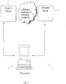
- the tomographic imaging system includes a light wave source block 4 to direct light waves into an object; a light wave detector block 6 to detect the intensity of waves emitted from the object and to convert the intensity of the waves into a digital signal representing waves emitted from the object; and a processor 8 to control the detector block and, optionally, the source block and to process the digital signal representing waves emitted from the object into a tomographic image on an output device.
- the processor is programmed to process the digital signal by representing the contribution of each wave into the detected intensity as a sum of an arbitrary integer number N of terms in a series and wherein each term in the series is an intensity of a wave reflected from an arbitrary surface within or outside the medium.
- Another example not forming part of the claimed invention is an apparatus comprising machine executable code for a method of tomographic imaging of medium including the steps of directing waves into a medium having a boundary S; detecting an intensity of light waves emitted from the medium by using non-contact measurements of waves outside the medium; and processing the detected intensity to generate a tomographic image by representing the contribution of each light wave into the detected intensity as a sum of an arbitrary integer number N of terms in a series and wherein each term in the series is an intensity of a light wave reflected from an arbitrary surface within or outside the medium.
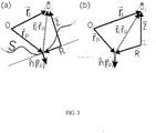
- FIG. 2 illustrates a general imaging model where there is a diffusive volume V delimited by surface S , which can be imaged.
- This diffusive medium is characterized by its absorption coefficient ⁇ a , the diffusion coefficient D, and the refractive index n in and is surrounded by a non-diffusive medium of refractive index n out .
- DPDW diffuse photon density waves
- r s is the position of the source
- r d is the position of the detector
- ⁇ 2 denotes the Laplacian operator
- ⁇ 2 ⁇ 2 ⁇ x 2 + ⁇ 2 ⁇ y 2 + ⁇ 2 ⁇ z 2
- ⁇ ( r s - r d ) is the Dirac's delta-function ( G. B. Arfken and H. J. Weber, Mathematical Methods for Physicists (Academic Press, New York, 1995 ).
- a complete Green's function G ( r s , r d ) can be defined, which models propagation of the diffuse photon waves from a point source to a point detector inside an arbitrarily shaped diffusive volume taking into account all boundaries present.
- S(r') is the source term (i.e., the strength of the light source at position r' given in units of energy density)
- V is the volume occupied by the diffusive medium.
- the source and detector are both inside the volume V .
- G r s r d g ⁇ r s ⁇ r d ⁇ 1 4 ⁇ ⁇ S G r s , r ′ ⁇ g ⁇ r ′ ⁇ r d ⁇ n ′ ⁇ g ⁇ r ′ ⁇ r d ⁇ G r s , r ′ ⁇ n ′ dS ′ , where n is the surface normal pointing into the non-diffusive medium.
- the boundary condition between the diffusive and non-diffusive medium Aronson, J. Opt. Soc. Am. A 16 (5): 1066-1071 , 1999 ; Aronson R, J.
- D is the medium's diffusion coefficient, where n is the unity, vector normal to surface S and pointing into the non-diffusive medium, and ⁇ , r s , and r d are defined above for Eq. (4).
- Eq. (8) is an integral equation that defines the complete Green function G (r s , r d ). Substituting a known function G (r s , r d ) into Eq. (5) allows the average intensity at a point r d inside the medium U( r d ) to be calculated for a given frequency ⁇ , which, in turn, allows the value of the average intensity of light at point r at time t, U (r , t ) represented by Eq. (1) to be calculated.
- KA Kirchhoff Approximation
- the KA therefore only considers first order reflections at an interface decomposed into planar components and in the case of a planar surface yields exact solutions.
- the Kirchhoff Approximation assumes that the surface is replaced at each point by its tangent plane.
- R s is the position of the source and r p is an arbitrary point on the surface
- U at any point r p of the surface S is given by the sum of the homogeneous incident intensity U inc and that of the light wave reflected from the local plane of normal n ( r p ).
- R ND K iC nd D ⁇ 2 ⁇ K 2 + 1 iC nd D ⁇ 2 ⁇ K 2 ⁇ 1 .
- R ND K ⁇ ⁇ ⁇ + ⁇ R ND R exp ⁇ i K ⁇ R d R .
- this invention describes and teaches the use of an iterative approach that uses an arbitrary number of multiple reflections from the boundary.
- This approach called the N-order Diffuse Reflection Boundary Method (DRBM) solves the exact integral Eq. (8) by iteratively decomposing each reflecting event into a sum of the series.
- Each term in a series is referred herein as an order of reflection.
- the series can be truncated when the sum meets convergence criteria defined below.
- the DRBM method finds the solution of the exact surface integral equation Eq. (8) by representing the solution as a sum of different orders of reflection.
- the number of DRBM orders needed may not exceed two, due to the fact that DPDWs are highly damped (i.e., suffer from strong absorption on propagation) so that multiple scattering of DPDWs along the boundary rarely takes place.
- About one or two first orders of the DRBM are crucial for Eq. (8) in the case of non-convex surfaces that create shadowing. This is because the 1 st or at most 2 nd order scattering with the convex interface models for the local illumination of the shadowed region from a secondary source reflected from the interface.
- Equation (DRBM. 1) is the main expression for the N-order DRBM.
- care must be taken when approaching values r' ⁇ r p where the Green function diverges.
- the Green function at r ' ⁇ r p should be replaced by so-called self-induction values.
- the 0 th -order G DRBM term is calculated by solving Eq. (8) using the KA method; all subsequent orders are calculated using equation (DRBM.1) in an iterative manner.
- the choice of the evolution step ⁇ will affect the speed of convergence and may be optimized.
- Other values of ⁇ may also be found, for example by using matrix pre-conditioners ( C. Macaskill and B. J. Kachoyan, Applied Optics 32, 2839-2847 (1993 )
- Time DRBM N > 2 N ⁇ 1 ⁇ Time ⁇ DRBM 2 ⁇ Time DRBM 1
- the DRBM can adaptively adjust the number of N-order reflections.
- the adaptive adjustment can be achieved by detecting complex boundaries, i.e., surfaces with high spatial variation, by monitoring the gradient of the boundary and automatically increasing the density of local surface discretization i.e., the number of discretization areas that define surface S at that local point, and the number of orders of reflections to include in the DRBM calculations.
- the spatial variation is high if substantial spatial changes occur in a range shorter than the decay length ( L d ) of the diffasive light wave.
- the adaptive adjustment can be achieved by monitoring the relative change in value of the calculated intensity added by each iteration step and stopping the number of iterations based on a convergence criterion.
- Typical criteria include limits on the relative change in a value of a function after each iterated step and limits on new contributions of the new iteration step to the overall value of the intensity.
- the iterative process can be stopped when the relative change in the value of intensity falls below about 0.1% to about 10%, preferably below 1%.
- the iterative process can be stopped when a new contribution falls under a certain threshold value ⁇ .
- the threshold value can be selected, for example, to be about twice the value of noise.
- DRBM surface integral equation
- r ⁇ S are taken or discarded in the surface integral equation (DRBM.1) can be selected so that only surface points that satisfy the condition: i thresh ⁇ g r s r p
- S(i tresh ) is the total surface considered in Eqs. (DRBM.1) and (DRBM.2), and g ( r ) is defined above by Eq. (4).
- a convenient approximation to the solution of Eq. (8) may be found by the method of images.
- r p is a point at the surface S and g is the infinite homogenous Green function defined by Eq. (4)
- ( R ⁇ , z ⁇ ) are defined above by Eq. (13)
- C nd and D are defined above for Eqs. (3) and (8), and their product represents a fictitious distance z ext from the real boundary at which the intensity is approximately zero.
- the infinite space Green function g is defined above, ⁇ S( r p ) is defined as the discretized surface area at point r p , C nd and D are defined above for Eqs. (3) and (8) and R and Z are defined above for Eq. (13).
- the method of the instant invention can be applied to non-contact measurements, as well as for any diffuse and non-diffuse interfaces as related to forming a tomographic image using light waves.
- contact measurement means measurement that takes place with the detector in contact with the surface or at a distance of less than about 1mm from the surface.
- non-contact measurement refers to measurements that take place with the detector at a distance of greater than 1mm from the surface.
- the contemplated waves include hear infrared or infra-red light.
- Contemplated modes of tomography include optical tomography, fluorescence-mediated tomography, near-field optical tomography, tomography with temperature waves and generally any surface-bounded inversion problems of tissues and other diffuse or diffuse-like or highly scattering medium.
- the term flux is defined as the power flowing through a surface S within an interval of time t and has units of power per area per second in the time-domain and units of power per area in the frequency or CW domain.
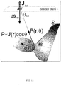
- ⁇ is the visibility factor, which is either unity, if both points r p and r can be joined by a straight line without intersecting the surface interface , i.e., when they are visible to each other, or zero otherwise.
- n is a unity vector normal to the surface of the detector or detector plane at point r of the non-scattering medium where the flux J is measured.
- the numerical aperture (NA) of the detector may be represented by a general function/which models light detection at different angles at the detector position r . Including function f , Eq.
- the present invention is a method for tomographic imaging of a diffusive medium comprising: (a) directing light waves into the diffusive medium having a boundary S:(b) detecting an intensity of light waves emitted from the diffusive medium by using non-contact measurements of light waves outside the diffusive medium, the non-contact measurements taking place with a detector at a distance of greater than 1 mm from the surface of the diffusive medium, wherein there is a non-diffusive medium between the detector and the diffusive medium; and(c) processing the detected intensity to generate a tomographic image using an N-order Green's function in a Diffuse Reflection Boundary Method, including representing the contribution of each wave into the detected intensity as a sum of an arbitrary integer number N of terms in a series, each term in the series being an intensity of a wave reflected from an arbitrary surface within or outside the diffusive medium.
- the medium fills an object of volume V, at least partially bounded by the boundary surface S.
- the light waves are directed into the medium by a source. Near-infrared light is most preferred.
- the light can be one or more sources specific to different chromophores, fluorophores or fluorescent imaging probes.
- Laser diodes can be used as light sources since they produce adequate power, are within the FDA class I and class II limits, and are stable, wavelength-specific and economical. Alternatively, filtered light can also be used.
- the processing step includes representing the contribution of each wave into the detected intensity as a sum of an arbitrary integer number N of terms in a series.
- Each term in the series is an intensity of a light wave reflected from an arbitrary surface within or outside the medium.
- the processing step can include solving the equation (DRBM.1) for an unknown function G DRBM (N) , where G (N) DRBM (r p ) is the N-order Green function in the DRBM approximation, C nd is as previously defined in Eq.
- D is the diffusion coefficient inside the diffusive medium
- n is a unity vector normal to boundary surface S and pointing into the non-diffusive medium
- c is a speed of light in the medium
- ⁇ a is an absorption coefficient
- ⁇ is an evolution step
- r s , and r p are source and detector positions respectively, and wherein the detector is located at the surface
- g is the Green's function for an infinite homogeneous diffusive medium with a wave number ⁇ .
- ) exp[ i ⁇
- , and N is an arbitrary integer not smaller than 1.
- the processing step can include solving the equation (DRBM.2) for an unknown function G DRBM (N) , where G (N) DRBM (r p ) is the N-order Green function in the DRBM approximation, C nd is as previously defined in Eq.
- D is the diffusion coefficient inside the diffusive medium
- n is a unity vector normal to boundary surface S and pointing into the non-diffusive medium
- c is a speed of light in the medium
- ⁇ a is an absorption coefficient
- ⁇ is an evolution step
- r s , and r p are source and detector positions respectively, and wherein the detector is located at the surface
- g is the Green's function for an infinite homogeneous diffusive medium with a wave number ⁇ .
- N is an arbitrary integer not smaller than 1
- U DRBM (N) ( r d ) is a light wave intensity at point r d
- S ( r' ) is the strength of the light source at position r ' expressed in units of energy density.
- the processing step can further include monitoring a gradient of the boundary surface to detect complex boundaries and automatically increasing a density of local surface discretization and the number N of terms in a series, if the boundary is complex.
- the processing step includes monitoring relative change in a value of the calculated intensity added by each term of the series and truncating the series by selecting a finite number N of terms in a series, when the relative change in a value of the calculated intensity meets convergence criteria.
- the medium being imaged is filling a volume V of arbitrary geometry.
- the volume or object has a fixed geometry whose surface is defined in terms of a continuous function f[z(x,y)] in cartesian, polar or cylindrical coordinates.
- Arbitrary geometry is preferred.
- the object can be a sample of a biological tissue or an animal, including a human.
- the object may also be non-mammalian, i.e., C. elegans, drosophila, etc.
- CW imaging uses light of constant intensity and measures either (1) the signal due to a distribution of excited fluorophores or (2) the attenuation of light (due to tissue absorption and scattering) employing multiple source-detector pairs.
- SNR signal-to-noise
- the technique is technically relatively simple and usually offers the best signal-to-noise (SNR) characteristics.
- SNR signal-to-noise
- it is not best suited for imaging of intrinsic tissue contrast since it usually introduces significant crosstalk between the calculations and imaging of absorption and scattering coefficients.
- the background optical properties are known, the method is well-suited for imaging fluorophore concentration in the steady-state.
- IM intensity modulated
- the IM technique offers two pieces of information, i.e., intensity attenuation and phase shift per source-detector pair. Amplitude and phase are usually uncorrelated measurements and can more efficiently resolve the absorption and scattering coefficient of intrinsic contrast.
- the technique can image two sets of information, fluorophore concentration and fluorescence lifetime.
- the time-resolved (TR) technique uses short pulses of light injected into the tissue.
- the technique resolves the distribution of times that the detected photons travel into the medium for multiple source-detector pairs.
- the time-resolved method offers a CW component for direct comparison with the CW system, but also intensity attenuation and phase-shift measurements at multiple-frequencies (via the Fourier transform) that can image intrinsic absorption and scattering, and also fluorophore concentration and fluorescence lifetime.
- the step of detection can be accomplished by non-contact measurements of emitted light wave intensity.
- non-contact measurements are made using a system of lenses, pinholes, apertures or any combination thereof.
- the method of the present invention can further include selecting a tomographic imaging method.
- the tomographic imaging method can be selected from the group consisting of diffuse optical tomography, fluorescence-mediated tomography, near-field optical tomography and thermal tomography.
- the preferred intrinsic absorbers, fluorochrome, or scatterer is selected from the group comprising hemoglobin, water, lipid, myoglobin, tissue chromophores and organelles.
- steps can also be repeated at predetermined intervals thereby allowing for the evaluation of emitted light in an object over time.
- Preferred fluorescent imaging probes that can be used with the present invention include, but are not limited to (1) probes that become activated after target interaction ( Weissleder, et al., Nature Biotech, 17:375-378, 1999 ; Bremer, et al., Nature Med., 7:743-748, 2001 ), (2) wavelength shifting beacons ( Tyagi et al., Nat. Biotechnol, 18:1191-1196, 2000 ), (3) multicolor fluorescence probes ( Tyagi et al., Nat.
- the method of the present invention may be used in combination with other imaging compositions and methods.
- the method of the present invention may be used in combination with other traditional imaging modalities such as X-ray, CT, PET, SPECT, and MRI.
- the method of the present invention may be used in combination with CT and MRI to obtain both anatomical and molecular information simultaneously, for instance by co-registration of a tomographic image with an image generated by another imaging modality.
- CT magnetic resonance imaging
- CT magnetic resonance imaging
- MRI magnetic resonance imaging
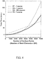
- Example 1 KA is Several Orders of Magnitude Faster Than More Rigorous Numerical Methods Such as FD or ET.
- the computing times achieved by using the KA as defined by equation (12) is compared to the extinction theorem (ET) and finite-differences solution (FD). While both ET and FD methods have a strong non-linear dependence as the area of the surface and the volume investigated increases, the KA method scales linearly with the size of the problem and more importantly it is faster than the ET and FD methods by almost three-orders of magnitude.
- the KA takes on the order of 90 seconds
- the ET takes on the order of 45 hours for only one forward solution.
- the KA is 1800 times faster. Similar conclusions can be reached for the FD method.
- Due to its linearity large numbers of surface points are possible with the KA, namely N ⁇ 10E+6, whereas with the ET, such large matrices are impossible to solve at the present time.
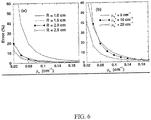
- the KA calculates the average intensity with errors that are less than 5% inside the volume (see FIG. 5 (a) and (c) ), but in the shadow regions near the interface, errors approach 20% or more. The errors in these regions are especially significant since they are at the boundary interfaces where the light sources and detectors would be likely located.
- FIG. 6 A comparison of the intensity generated by a point source in a cylindrical geometry using the KA versus the exact solution, (ET) with different several radius and optical properties is shown in FIG. 6 .
- Error in the KA were plotted against absorption coefficient for different radii and scattering coefficients for a case of a smooth cylinder (i.e., no shadowing effect).
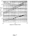
- Computation times of the first four orders of the DRBM are shown in FIG. 7 .
- the computation time is still linear even when dealing with N-order approximations. While the computation time increases the linear dependence with the number of surface points remains since there is not matrix inversion involved in the DRBM method.
- the computations times achieved by the different orders are very close and orders of magnitude lower than numerical methods shown in FIG. 4 .
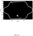
- FIG. 9 depicts reconstruction of the simulated geometry in (a) using the ET method, (b) the 2 nd order DRBM for exact geometry, (c) 2 nd order DRBM for an approximate boundary indicated by the ellipsoid solid line and (d) transmittance geometry using the expression of a slab.
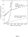
- FIG. 9 demonstrates the effect of using geometrically accurate or geometrically approximate forward models in modeling complex boundaries and FIG. 10 depicts reconstruction of simulated geometry in FIG. 9(a) using the KA method for the exact geometry.
- the image demonstrates the inefficiency of the KA method to image small dimensions.
- two fluorescing objects 200nM
- FIG. 9(a) the forward field has been calculated analytically using an exact solution (Extinction Theorem).
- FIG. 9(b) depicts the reconstruction obtained using the 2 nd order DRBM.
- FIG. 9(c) depicts the image reconstruction using an elliptical outline also using the 2 nd order DRBM and in FIG.
- FIG. 10 illustrates the results obtained when using the KA method.
- the KA is not capable of reconstructing the objects accurately in this case due to the convex complex boundary and the relatively small dimensions of the problem.
- the results are similar to those of the slab inversion ( FIG. 9(d) ).
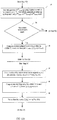
- FIGs. 12A-12C a data flow chart and a control diagram 10 is provided depicting the operation of the method of the present invention.
- the method of the present invention Given that the light waves are generated by a total of N src sources and detected by a total of N det detectors, the method of the present invention generates data that can be processed into a tomographic image by a system of FIG. 1 .
- step 20 the description of a boundary surface S of a volume V to be imaged is provided as either a collection of points or an equation.
- step 22 the surface S is discretized. If necessary, the number of discrete areas in those regions where the surface gradient is higher is increased to improve computation time and accuracy.
- step 24 a check is made to determine whether all sources contributed into the computed intensity. If all sources contributed, then step 48 is performed. If there are sources whose contribution was not counted, step 26 is performed.
- a source number isrc is selected and light wave corresponding to the selected source are directed into the volume V.
- the source term distribution S ( r ) for source isrc is generated numerically as defined for Eq. (5).
- the non-contact formulation presented above by Eqs. (20) - (24) can be used to find flux and intensity at the boundary S generated by the selected source.
- step 28 a check is made to determine whether all the detectors from the total number of Ndet were used to detect the signal generated by the detector selected in step 26. If all detectors were used, control is passed back to step 24. If there are detectors that were not used to detect the selected source, step 30 is performed.
- a detector number i det is selected.
- a threshold value thresh is selected such that a contribution of a point rp on the boudary S into the intensity at the detector will be considered if i thresh ⁇ g ( r s , r p )
- the zero-th order Green function of Eq.(DRBM.3) is found at each point of boundary S that satisfies the above condition.
- Green's function G DRBM N is iteratively generated using Eq.(DRBM.1) for the desired order N. Alternatively, all orders N are generated until such order that ( G DRBM N ⁇ G DRBM N ⁇ 1 / G DRBM N ) is less than a selected value.
- step 34 a determination is made of whether contact measurements are used. If contact measurements are used (an option outside the present invention) step 36 is performed. If non-contact measurements are used, step 38 is performed.
- step 36 the average intensity U( r d ) is computed using Eq.(DRBM.2) for each point r d where g ( r s , r d )
- step 38 a function f is selected that models the numerical aperture of the non-contact detector and function ⁇ is computed by using Eq.(23).
- step 40 intensity U (r p ) is computed using Eq.(DRBM.1) at each point r p of the surface S where g ( r s , r p )
- step 42 the surface flux values J n ( r p ) are computed by means of Eq. (20).
- step 44 the flux J at non-contact detectors is computed using the surface flux values J n ( r p ) in Eq. (23) and (24).
- step 48 values of the average intensity U ( r s , r d ) for all N src sources and N det detectors is provided to a processor, programmed to process intensity values into a tomographic image and output the image to an I/O device.
- a computer usable medium can include a readable memory device, such as a hard drive device, a CD-ROM, a DVD-ROM, or a computer diskette, having computer readable program code segments stored thereon.
- the computer readable medium can also include a communications or transmission medium, such as a bus or a communications link, either optical, wired, or wireless, having program code segments carried thereon as digital or analog data signals.
Claims (10)
- Verfahren zur tomographischen Abbildung eines diffusen Mediums, umfassend:(a) das Richten von Lichtwellen in das diffuse Medium, das eine Grenzfläche (S) aufweist;(b) das Erfassen einer Intensität von Lichtwellen, die von dem diffusen Medium emittiert werden, durch die Anwendung kontaktfreier Messungen von Lichtwellen außerhalb des diffusen Mediums, wobei die kontaktfreien Messungen mit einem Detektor (6) in einem Abstand von mehr als 1 mm von der Oberfläche des diffusen Mediums erfolgen, wobei zwischen dem Detektor (6) und dem diffusen Medium ein nicht-diffuses Medium vorhanden ist;dadurch gekennzeichnet, dass das Verfahren ferner umfasst:
(c) das Verarbeiten der erfassten Intensität zum Erzeugen einer tomographischen Abbildung unter Anwendung einer Green'schen Funktion N-ter Ordnung in einem diffusen Grenzflächenreflexionsverfahren, umfassend die Darstellung des Beitrags jeder Welle zur erfassten Intensität als Summe einer beliebigen ganzen Zahl N von Termen in einer Reihe, wobei jeder Term in der Reihe eine Intensität einer Welle ist, die von einer beliebigen Fläche innerhalb oder außerhalb des diffusen Mediums reflektiert wird. - Verfahren nach Anspruch 1, wobei das diffuse Medium ein Objekt eines Volumens V füllt, das zumindest teilweise durch die Grenzfläche (S) begrenzt ist, wobei die Geometrie des Volumens beliebig ist.
- Verfahren nach Anspruch 1, wobei Schritt (c) ferner umfasst:das Überwachen eines Gradienten der Grenzfläche, um komplexe Begrenzungen zu detektieren; unddas automatische Erhöhen einer Dichte lokaler Flächendiskretierung und der Anzahl N von Termen, wenn die Begrenzung komplex ist.
- Verfahren nach Anspruch 1, wobei Schritt (c) ferner umfasst:
das Überwachen einer relativen Änderung eines Werts der berechneten Intensität, die durch jeden Term der Reihe hinzugefügt wird, und das Abschneiden der Reihe durch die Wahl einer finiten Anzahl N von Termen in der Reihe, wenn die relative Änderung eines Werts der berechneten Intensität Konvergenzkriterien erfüllt. - Verfahren nach Anspruch 1, wobei Schritt (c) ferner umfasst:das Überwachen eines Gradienten der Grenzfläche (S) zum Detektieren von komplexen Grenzflächen;das automatische Erhöhen einer Dichte lokaler Flächendiskretierung und der Anzahl N von Termen in der Reihe, wenn die Begrenzung komplex ist; unddas Optimieren eines Evolutionsschritts τ durch Zuordnen eines Werts von etwa τ =2imag{k}/√W + 1, wobei k eine diffuse Wellenzahl k = √(-µa /D + iω/c) bei einer Modulationsfrequenz ω, c die Geschwindigkeit des Lichts in dem Medium, µa ein Absorptionskoeffizient, D der Diffusionskoeffizient in dem diffusen Medium und W ein mittlerer Durchmesser des diffusen Mediums ist.
- Verfahren nach Anspruch 1, ferner umfassend einen Schritt des Auswählens einer tomographischen Abbildungsmethode, wobei die tomographische Abbildungsmethode ausgewählt wird aus der Gruppe, die aus einer diffusen optischen Tomographie, einer fluoreszenz-mediierten Tomographie, einer optischen Nahfeld-Tomographie und einer thermischen Tomographie besteht.
- Verfahren nach Anspruch 1, wobei das diffuse Medium ein biologisches Gewebe ist.
- Verfahren nach Anspruch 1, wobei die Lichtwellen eine kontinuierliche Welle, CW, zeitaufgelöst, TR, intensitätsmoduliert, IM oder eine Kombination davon sind.
- Verfahren nach Anspruch 1, wobei die Lichtwellen nahes Infrarotlicht oder Infrarotlicht sind.
- Verfahren nach Anspruch 2, ferner umfassend:Verabreichen einer fluoreszierenden Abbildungssonde an das Objekt; unddas Detektieren fluoreszierenden Lichts, das von dem Objekt von mehreren Punkten emittiert wird, wobei das tomographische Bild einem dreidimensionalen Zielbereich in dem Objekt und einer Quantität einer fluoreszierenden Abbildungssonde in dem Zielbereich entspricht.
Priority Applications (1)
| Application Number | Priority Date | Filing Date | Title |
|---|---|---|---|
| EP11182730.9A EP2410315B1 (de) | 2002-06-04 | 2003-06-04 | Bildgebungsdatenträger mit willkürlichen Geometrien bei Kontakt- und kontaktloser Tomographie |
Applications Claiming Priority (3)
| Application Number | Priority Date | Filing Date | Title |
|---|---|---|---|
| US38593102P | 2002-06-04 | 2002-06-04 | |
| US385931P | 2002-06-04 | ||
| PCT/US2003/017558 WO2003102558A1 (en) | 2002-06-04 | 2003-06-04 | Imaging volumes with arbitrary geometries in contact and non-contact tomography |
Related Child Applications (2)
| Application Number | Title | Priority Date | Filing Date |
|---|---|---|---|
| EP11182730.9A Division EP2410315B1 (de) | 2002-06-04 | 2003-06-04 | Bildgebungsdatenträger mit willkürlichen Geometrien bei Kontakt- und kontaktloser Tomographie |
| EP11182730.9A Division-Into EP2410315B1 (de) | 2002-06-04 | 2003-06-04 | Bildgebungsdatenträger mit willkürlichen Geometrien bei Kontakt- und kontaktloser Tomographie |
Publications (2)
| Publication Number | Publication Date |
|---|---|
| EP1514093A1 EP1514093A1 (de) | 2005-03-16 |
| EP1514093B1 true EP1514093B1 (de) | 2021-04-28 |
Family
ID=29712219
Family Applications (2)
| Application Number | Title | Priority Date | Filing Date |
|---|---|---|---|
| EP03734381.1A Expired - Lifetime EP1514093B1 (de) | 2002-06-04 | 2003-06-04 | Abbildung von volumen mit beliebigen geometrien in nichtberührenden tomographie |
| EP11182730.9A Expired - Lifetime EP2410315B1 (de) | 2002-06-04 | 2003-06-04 | Bildgebungsdatenträger mit willkürlichen Geometrien bei Kontakt- und kontaktloser Tomographie |
Family Applications After (1)
| Application Number | Title | Priority Date | Filing Date |
|---|---|---|---|
| EP11182730.9A Expired - Lifetime EP2410315B1 (de) | 2002-06-04 | 2003-06-04 | Bildgebungsdatenträger mit willkürlichen Geometrien bei Kontakt- und kontaktloser Tomographie |
Country Status (4)
| Country | Link |
|---|---|
| US (4) | US20050283071A1 (de) |
| EP (2) | EP1514093B1 (de) |
| AU (1) | AU2003239968A1 (de) |
| WO (1) | WO2003102558A1 (de) |
Families Citing this family (70)
| Publication number | Priority date | Publication date | Assignee | Title |
|---|---|---|---|---|
| US7383076B2 (en) | 2000-11-27 | 2008-06-03 | The General Hospital Corporation | Fluorescence-mediated molecular tomography |
| ATE336717T1 (de) | 2001-05-17 | 2006-09-15 | Xenogen Corp | Verfahren und vorrichtung zur feststellung von zieltiefe, helligkeit und grösse in einer körperregion |
| US7298415B2 (en) * | 2001-07-13 | 2007-11-20 | Xenogen Corporation | Structured light imaging apparatus |
| WO2003057175A2 (en) | 2002-01-02 | 2003-07-17 | Visen Medical, Inc. | Amine functionalized superparamagnetic nanoparticles for the synthesis of bioconjugates and uses therefor |
| AU2003239968A1 (en) | 2002-06-04 | 2003-12-19 | Visen Medical, Inc. | Imaging volumes with arbitrary geometries in contact and non-contact tomography |
| US7616985B2 (en) | 2002-07-16 | 2009-11-10 | Xenogen Corporation | Method and apparatus for 3-D imaging of internal light sources |
| US7599731B2 (en) | 2002-07-16 | 2009-10-06 | Xenogen Corporation | Fluorescent light tomography |
| EP1593095B1 (de) | 2003-02-05 | 2019-04-17 | The General Hospital Corporation | Verfahren und vorrichtung zur bilderzeugung mittels optischer freiraumtomographie für diffuse medien |
| US7729739B2 (en) * | 2003-12-03 | 2010-06-01 | The Board Of Trustees Of The Leland Stanford Junior University | Heat diffusion based detection of structures of interest in medical images |
| GB0409572D0 (en) * | 2004-04-29 | 2004-06-02 | Univ Sheffield | High resolution imaging |
| AT414212B (de) * | 2004-07-20 | 2006-10-15 | Upper Austrian Res Gmbh | Thermoakustisches tomographieverfahren und thermoakustischer tomograph |
| US20110152249A1 (en) * | 2004-12-23 | 2011-06-23 | The General Hospital Corporation | Evaluating central nervous system |
| US8044996B2 (en) * | 2005-05-11 | 2011-10-25 | Xenogen Corporation | Surface construction using combined photographic and structured light information |
| EP1729261A1 (de) | 2005-06-01 | 2006-12-06 | Deutsches Krebsforschungszentrum Stiftung Des Öffentlichen Rechts | Verfahren zur tomographische Rekonstruktion |
| US20080218732A1 (en) * | 2005-07-27 | 2008-09-11 | University Of Massachusetts Lowell | Infrared Scanner for Biological Applications |
| JP5416970B2 (ja) | 2005-09-02 | 2014-02-12 | ビセン メディカル, インコーポレイテッド | ニコチン酸及びピコリン酸誘導近赤外線蛍光団 |
| GR1005346B (el) * | 2005-12-20 | 2006-11-02 | Ιδρυμα Τεχνολογιας Και Ερευνας | Αφαιρεση συνοριακων επιφανειων σε διαχυτα μεσα |
| WO2007136413A2 (en) | 2005-12-22 | 2007-11-29 | Visen Medical, Inc. | Biocompatible fluorescent metal oxide nanoparticles |
| DE602006020618D1 (de) | 2005-12-22 | 2011-04-21 | Visen Medical Inc | Kombiniertes röntgen- und optisches tomographie-bildgebungssystem |
| US10335038B2 (en) | 2006-08-24 | 2019-07-02 | Xenogen Corporation | Spectral unmixing for in-vivo imaging |
| US10775308B2 (en) | 2006-08-24 | 2020-09-15 | Xenogen Corporation | Apparatus and methods for determining optical tissue properties |
| DK2118206T3 (en) | 2007-02-09 | 2018-06-18 | Visen Medical Inc | POLYCYCLOF COLORS AND APPLICATION THEREOF |
| WO2008109832A2 (en) * | 2007-03-08 | 2008-09-12 | Visen Medical, Inc. | Viable near-infrared fluorochrome labeled cells and methods of making and using same |
| US8323694B2 (en) * | 2007-05-09 | 2012-12-04 | Nanoprobes, Inc. | Gold nanoparticles for selective IR heating |
| US8492734B2 (en) | 2007-10-19 | 2013-07-23 | Visen Medical, Inc. | Imaging systems featuring waveguiding compensation |
| WO2009077626A1 (es) * | 2007-12-19 | 2009-06-25 | Fundacion Para La Investigacion Biomedica Del Hospital Gregorio Marañon | Incubadora para imagen con radiacion no ionizante |
| WO2009092062A2 (en) | 2008-01-18 | 2009-07-23 | Visen Medical, Inc. | Fluorescent imaging agents |
| US8685370B2 (en) | 2008-03-14 | 2014-04-01 | Visen Medical, Inc. | Integrin targeting agents and in-vivo and in-vitro imaging methods using the same |
| EP2265165A2 (de) * | 2008-03-17 | 2010-12-29 | Or-Nim Medical Ltd. | Vorrichtung zur nicht-invasiven akustooptischen überwachung |
| US8918163B2 (en) | 2008-03-25 | 2014-12-23 | Visen Medical, Inc. | Animal holder for in vivo tomographic imaging with multiple modalities |
| CN102137618B (zh) | 2008-07-25 | 2015-06-17 | 健康与环境慕尼黑德国研究中心赫姆霍茨中心(有限公司) | 组织生物标志物的定量多光谱光声断层摄影(msot) |
| US8433382B2 (en) | 2008-09-30 | 2013-04-30 | Covidien Lp | Transmission mode photon density wave system and method |
| JP5566456B2 (ja) | 2009-06-29 | 2014-08-06 | ヘルムホルツ・ツェントルム・ミュンヒェン・ドイチェス・フォルシュンクスツェントルム・フューア・ゲズントハイト・ウント・ウムベルト(ゲーエムベーハー) | 被写体を熱音響撮像するための撮像装置及び撮像方法、コンピュータプログラム並びにコンピュータで読み取り可能な記憶媒体を備える装置 |
| EP2459987A1 (de) | 2009-07-27 | 2012-06-06 | Helmholtz Zentrum München Deutsches Forschungszentrum für Gesundheit und Umwelt (GmbH) | Bildgebungsvorrichtung und verfahren zur optoakustischen bildgebung von kleintieren |
| WO2011025950A2 (en) | 2009-08-28 | 2011-03-03 | Visen Medical, Inc. | Systems and methods for tomographic imaging in diffuse media using a hybrid inversion technique |
| JP5945226B2 (ja) * | 2009-09-22 | 2016-07-05 | ビセン メディカル, インコーポレイテッド | 拡散媒質の仮想屈折率整合のためのシステムおよび方法 |
| US9220412B2 (en) * | 2009-11-19 | 2015-12-29 | Modulated Imaging Inc. | Method and apparatus for analysis of turbid media via single-element detection using structured illumination |
| US20110123452A1 (en) * | 2009-11-25 | 2011-05-26 | Nanoprobes, Inc. | Metal oligomers and polymers and their use in biology and medicine |
| JP5641773B2 (ja) * | 2010-04-28 | 2014-12-17 | キヤノン株式会社 | 測定装置 |
| EP2589025A2 (de) * | 2010-07-01 | 2013-05-08 | Thomson Licensing | Verfahren zur schätzung der lichtstreuung |
| US20140088415A1 (en) * | 2010-12-13 | 2014-03-27 | Andreas H. Hielscher | Medical imaging devices, methods, and systems |
| TWI534756B (zh) * | 2011-04-29 | 2016-05-21 | 國立成功大學 | 運動編碼影像及生成模組、影像處理模組及運動展示模組 |
| JP6122840B2 (ja) | 2011-05-09 | 2017-04-26 | ビセン メディカル, インコーポレイテッド | 炭酸脱水酵素標的化剤およびそれの使用方法 |
| CN102298256B (zh) * | 2011-08-24 | 2012-11-21 | 浙江大学 | 俯仰多视角的悬浮式360度视场空间三维显示装置 |
| CN104245954A (zh) | 2012-03-30 | 2014-12-24 | 文森医学公司 | 细菌成像剂及其使用方法 |
| US9371362B2 (en) | 2012-08-15 | 2016-06-21 | Visen Medical, Inc. | Prostate specific antigen agents and methods of using same for prostate cancer imaging |
| US10743768B2 (en) | 2012-10-15 | 2020-08-18 | Visen Medical, Inc. | Systems, methods, and apparatus for imaging of diffuse media featuring cross-modality weighting of fluorescent and bioluminescent sources |
| US8892192B2 (en) | 2012-11-07 | 2014-11-18 | Modulated Imaging, Inc. | Efficient modulated imaging |
| EP2742854B1 (de) | 2012-12-11 | 2021-03-10 | iThera Medical GmbH | Tragbare Vorrichtung und Verfahren für tomographische optoakustische Bildgebung eines Objekts |
| EP2754388B1 (de) | 2013-01-15 | 2020-09-09 | Helmholtz Zentrum München Deutsches Forschungszentrum für Gesundheit und Umwelt GmbH | System und Verfahren zur optoakustischen Abbildung eines Objekts mit verbesserter Qualität und hoher Rate |
| EP2970342B1 (de) | 2013-03-15 | 2024-01-24 | VisEn Medical, Inc. | Substituiertes silaxanthenium-rot für nahinfrarot-fluorchrome zur in-vitro- und in-vivo-bildgebung und -erkennung |
| WO2014144702A2 (en) | 2013-03-15 | 2014-09-18 | Visen Medical, Inc. | 4,4-disubstituted cyclohexyl bridged heptamethine cyanine dyes and uses thereof |
| CN103750824B (zh) * | 2014-01-17 | 2015-12-02 | 天津大学 | 一种针对小动物荧光层析成像系统的信息提取方法 |
| CN104665770B (zh) * | 2015-02-10 | 2017-03-01 | 天津大学 | 一种用于近红外光脑功能研究的自引导扩散光层析成像方法 |
| CN106331442B (zh) * | 2015-07-02 | 2021-01-15 | 松下知识产权经营株式会社 | 摄像装置 |
| US9730649B1 (en) | 2016-09-13 | 2017-08-15 | Open Water Internet Inc. | Optical imaging of diffuse medium |
| WO2019067180A1 (en) | 2017-09-29 | 2019-04-04 | Perkinelmer Health Sciences, Inc. | NIR-SWIR FLUORESCENT COMPOUNDS FOR IMAGING AND DETECTION |
| US10778911B2 (en) | 2018-03-31 | 2020-09-15 | Open Water Internet Inc. | Optical transformation device for imaging |
| US10778912B2 (en) | 2018-03-31 | 2020-09-15 | Open Water Internet Inc. | System and device for optical transformation |
| US10506181B2 (en) | 2018-03-31 | 2019-12-10 | Open Water Internet Inc. | Device for optical imaging |
| US10966612B2 (en) | 2018-06-14 | 2021-04-06 | Open Water Internet Inc. | Expanding beam optical element |
| US10962929B2 (en) | 2018-09-14 | 2021-03-30 | Open Water Internet Inc. | Interference optics for optical imaging device |
| US10874370B2 (en) | 2019-01-28 | 2020-12-29 | Open Water Internet Inc. | Pulse measurement in optical imaging |
| US10955406B2 (en) | 2019-02-05 | 2021-03-23 | Open Water Internet Inc. | Diffuse optical imaging with multiple beams |
| US11320370B2 (en) | 2019-06-26 | 2022-05-03 | Open Water Internet Inc. | Apparatus for directing optical and acoustic signals |
| US11581696B2 (en) | 2019-08-14 | 2023-02-14 | Open Water Internet Inc. | Multi-channel laser |
| US11622686B2 (en) | 2019-11-22 | 2023-04-11 | Open Water Internet, Inc. | Optical imaging with unshifted reference beam |
| US11819318B2 (en) | 2020-04-27 | 2023-11-21 | Open Water Internet Inc. | Optical imaging from light coherence |
| US11259706B2 (en) | 2020-05-19 | 2022-03-01 | Open Water Internet Inc. | Dual wavelength imaging and out of sample optical imaging |
| US11559208B2 (en) | 2020-05-19 | 2023-01-24 | Open Water Internet Inc. | Imaging with scattering layer |
Citations (1)
| Publication number | Priority date | Publication date | Assignee | Title |
|---|---|---|---|---|
| WO1995023961A1 (en) * | 1994-03-01 | 1995-09-08 | The Trustees Of The University Of Pennsylvania | Methods and apparatus for imaging with diffuse light |
Family Cites Families (42)
| Publication number | Priority date | Publication date | Assignee | Title |
|---|---|---|---|---|
| US4281645A (en) | 1977-06-28 | 1981-08-04 | Duke University, Inc. | Method and apparatus for monitoring metabolism in body organs |
| JP2645718B2 (ja) * | 1988-02-17 | 1997-08-25 | 住友電気工業株式会社 | 光ct装置 |
| US4920491A (en) | 1988-05-16 | 1990-04-24 | General Electric Company | Enhancement of image quality by utilization of a priori information |
| US5090415A (en) | 1989-02-14 | 1992-02-25 | Hamamatsu Photonics Kabushiki Kaisha | Examination apparatus |
| US5070455A (en) | 1989-11-22 | 1991-12-03 | Singer Imaging, Inc. | Imaging system and method using scattered and diffused radiation |
| US5699798A (en) | 1990-08-10 | 1997-12-23 | University Of Washington | Method for optically imaging solid tumor tissue |
| JPH04122248A (ja) | 1990-09-13 | 1992-04-22 | Res Dev Corp Of Japan | 光断層像画像化装置 |
| JP3217107B2 (ja) | 1992-02-14 | 2001-10-09 | 科学技術振興事業団 | 蛍光断層像測定装置 |
| DE69226512T2 (de) | 1992-03-12 | 1999-04-22 | Ibm | Verfahren zur Bildverarbeitung |
| US6304771B1 (en) * | 1993-10-29 | 2001-10-16 | The Trustees Of The University Of Pennsylvania | Systems and methods for imaging fluorophores |
| JP3433508B2 (ja) | 1993-12-01 | 2003-08-04 | 浜松ホトニクス株式会社 | 散乱吸収体計測方法及び散乱吸収体計測装置 |
| US5391877A (en) | 1994-01-26 | 1995-02-21 | Marks; Michael A. | Combined imaging scanner |
| US5590660A (en) | 1994-03-28 | 1997-01-07 | Xillix Technologies Corp. | Apparatus and method for imaging diseased tissue using integrated autofluorescence |
| JPH08131445A (ja) | 1994-11-14 | 1996-05-28 | Hitachi Ltd | 光計測装置 |
| DE4445214C2 (de) | 1994-12-17 | 2000-06-29 | Laser & Med Tech Gmbh | Verfahren zur Bestimmung und Rekonstruktion räumlicher Verteilungen und Intensitäten von Fluoreszenzfarbstoffen und Vorrichtung zur Durchführung des Verfahrens |
| WO1996020638A1 (en) | 1995-01-03 | 1996-07-11 | Non-Invasive Technology, Inc. | Optical coupler for in vivo examination of biological tissue |
| CA2230228C (en) | 1995-08-24 | 2006-11-14 | Purdue Research Foundation | Fluorescence lifetime-based imaging and spectroscopy in tissues and other random media |
| JP3662376B2 (ja) * | 1996-05-10 | 2005-06-22 | 浜松ホトニクス株式会社 | 内部特性分布の計測方法および装置 |
| JP3654325B2 (ja) | 1997-02-13 | 2005-06-02 | 富士写真フイルム株式会社 | 蛍光検出装置 |
| US5762607A (en) | 1997-03-19 | 1998-06-09 | Schotland; John Carl | Emission tomography system and method using direct reconstruction of scattered radiation |
| US6041132A (en) | 1997-07-29 | 2000-03-21 | General Electric Company | Computed tomography inspection of composite ply structure |
| US6081322A (en) | 1997-10-16 | 2000-06-27 | Research Foundation Of State Of New York | NIR clinical opti-scan system |
| JP3771364B2 (ja) | 1997-12-12 | 2006-04-26 | 浜松ホトニクス株式会社 | 光ct装置及び画像再構成方法 |
| US6205347B1 (en) | 1998-02-27 | 2001-03-20 | Picker International, Inc. | Separate and combined multi-modality diagnostic imaging system |
| US6377842B1 (en) | 1998-09-22 | 2002-04-23 | Aurora Optics, Inc. | Method for quantitative measurement of fluorescent and phosphorescent drugs within tissue utilizing a fiber optic probe |
| US6205353B1 (en) * | 1998-12-22 | 2001-03-20 | Research Foundation Of Cuny | Time-resolved optical backscattering tomographic image reconstruction in scattering turbid media |
| US6028790A (en) | 1999-01-07 | 2000-02-22 | Macronix International Co., Ltd. | Method and device for programming a non-volatile memory cell by controlling source current pulldown rate |
| US6219279B1 (en) | 1999-10-29 | 2001-04-17 | Zilog, Inc. | Non-volatile memory program driver and read reference circuits |
| US7581191B2 (en) | 1999-11-15 | 2009-08-25 | Xenogen Corporation | Graphical user interface for 3-D in-vivo imaging |
| US6377841B1 (en) | 2000-03-31 | 2002-04-23 | Vanderbilt University | Tumor demarcation using optical spectroscopy |
| US7383076B2 (en) * | 2000-11-27 | 2008-06-03 | The General Hospital Corporation | Fluorescence-mediated molecular tomography |
| US6615063B1 (en) * | 2000-11-27 | 2003-09-02 | The General Hospital Corporation | Fluorescence-mediated molecular tomography |
| US6825928B2 (en) | 2001-12-19 | 2004-11-30 | Wisconsin Alumni Research Foundation | Depth-resolved fluorescence instrument |
| KR100476888B1 (ko) | 2002-04-04 | 2005-03-17 | 삼성전자주식회사 | 온도보상기능을 가진 멀티비트 플래쉬메모리 |
| AU2003239968A1 (en) | 2002-06-04 | 2003-12-19 | Visen Medical, Inc. | Imaging volumes with arbitrary geometries in contact and non-contact tomography |
| US7616985B2 (en) | 2002-07-16 | 2009-11-10 | Xenogen Corporation | Method and apparatus for 3-D imaging of internal light sources |
| EP1593095B1 (de) | 2003-02-05 | 2019-04-17 | The General Hospital Corporation | Verfahren und vorrichtung zur bilderzeugung mittels optischer freiraumtomographie für diffuse medien |
| JP2008522761A (ja) | 2004-12-08 | 2008-07-03 | ザ・ゼネラル・ホスピタル・コーポレーション | 規準化された蛍光又は生物発光撮像のためのシステムと方法 |
| DE602006020618D1 (de) | 2005-12-22 | 2011-04-21 | Visen Medical Inc | Kombiniertes röntgen- und optisches tomographie-bildgebungssystem |
| WO2009009178A2 (en) | 2007-04-06 | 2009-01-15 | The General Hospital Corporation | Systems and methods for optical imaging using early arriving photons |
| US8492734B2 (en) | 2007-10-19 | 2013-07-23 | Visen Medical, Inc. | Imaging systems featuring waveguiding compensation |
| JP5223738B2 (ja) | 2009-03-12 | 2013-06-26 | 富士電機株式会社 | 飲料供給装置 |
-
2003
- 2003-06-04 AU AU2003239968A patent/AU2003239968A1/en not_active Abandoned
- 2003-06-04 EP EP03734381.1A patent/EP1514093B1/de not_active Expired - Lifetime
- 2003-06-04 EP EP11182730.9A patent/EP2410315B1/de not_active Expired - Lifetime
- 2003-06-04 WO PCT/US2003/017558 patent/WO2003102558A1/en not_active Application Discontinuation
-
2004
- 2004-12-03 US US11/003,936 patent/US20050283071A1/en not_active Abandoned
-
2010
- 2010-01-15 US US12/688,661 patent/US8170651B2/en not_active Expired - Lifetime
-
2012
- 2012-04-30 US US13/460,005 patent/US8812088B2/en not_active Expired - Lifetime
-
2014
- 2014-07-22 US US14/338,061 patent/US8948852B2/en not_active Expired - Lifetime
Patent Citations (1)
| Publication number | Priority date | Publication date | Assignee | Title |
|---|---|---|---|---|
| WO1995023961A1 (en) * | 1994-03-01 | 1995-09-08 | The Trustees Of The University Of Pennsylvania | Methods and apparatus for imaging with diffuse light |
Also Published As
| Publication number | Publication date |
|---|---|
| EP2410315A3 (de) | 2014-07-30 |
| AU2003239968A1 (en) | 2003-12-19 |
| WO2003102558A1 (en) | 2003-12-11 |
| US8170651B2 (en) | 2012-05-01 |
| US8948852B2 (en) | 2015-02-03 |
| US20140336505A1 (en) | 2014-11-13 |
| EP2410315B1 (de) | 2020-04-01 |
| US20050283071A1 (en) | 2005-12-22 |
| WO2003102558A8 (en) | 2004-04-01 |
| US8812088B2 (en) | 2014-08-19 |
| US20130114069A1 (en) | 2013-05-09 |
| EP1514093A1 (de) | 2005-03-16 |
| EP2410315A2 (de) | 2012-01-25 |
| US20100292567A1 (en) | 2010-11-18 |
Similar Documents
| Publication | Publication Date | Title |
|---|---|---|
| EP1514093B1 (de) | Abbildung von volumen mit beliebigen geometrien in nichtberührenden tomographie | |
| Ren et al. | Frequency domain optical tomography based on the equation of radiative transfer | |
| EP1968431B1 (de) | Kombiniertes röntgen- und optisches tomographie-bildgebungssystem | |
| Pogue et al. | Three-dimensional simulation of near-infrared diffusion in tissue: boundary condition and geometry analysis for finite-element image reconstruction | |
| CN102781307B (zh) | 用于漫射性介质虚拟折射率匹配的系统和方法 | |
| Chu et al. | Light transport in biological tissue using three-dimensional frequency-domain simplified spherical harmonics equations | |
| Charette et al. | An overview on recent radiation transport algorithm development for optical tomography imaging | |
| Zhu et al. | A three-dimensional finite element model and image reconstruction algorithm for time-domain fluorescence imaging in highly scattering media | |
| CN102821677A (zh) | 光声成像装置、光声成像方法和程序 | |
| Mozumder et al. | Time-domain diffuse optical tomography utilizing truncated Fourier series approximation | |
| Murad et al. | Reconstruction and localization of tumors in breast optical imaging via convolution neural network based on batch normalization layers | |
| US7142304B1 (en) | Method and system for enhanced imaging of a scattering medium | |
| Fujii et al. | Numerical modeling of photon migration in human neck based on the radiative transport equation | |
| Kazancı et al. | Mathematical method for diffuse optical tomography imaging: a research study | |
| Busch Jr | Computer-aided, multi-modal, and compression diffuse optical studies of breast tissue | |
| Wang | An EM‐like reconstruction method for diffuse optical tomography | |
| Kazanci | Non-contact head laser tomography | |
| Aggrawal | Studies and validation of solutions to the forward problem of fluorescence diffuse optical tomography | |
| Ruan et al. | An experimental investigation on two-dimensional shape-based diffuse optical tomography | |
| EP1221033B1 (de) | Verfahren und vorrichtung zur kontrastverbesserten abbildung eines streuenden mediums | |
| Kumar | Light propagation through biological tissue: comparison between Monte Carlo simulation and deterministic models | |
| Hänninen | Image reconstruction and uncertainty quantification in quantitative photoacoustic tomography | |
| Charette et al. | Optical tomography as an inverse radiation problem | |
| Bjoern et al. | The influence of Heterogeneous optical properties upon fluorescence diffusion Tomography of small animals | |
| Bjoern et al. | The influence of heterogeneous optical properties on fluorescence diffusion tomography of small animals |
Legal Events
| Date | Code | Title | Description |
|---|---|---|---|
| PUAI | Public reference made under article 153(3) epc to a published international application that has entered the european phase |
Free format text: ORIGINAL CODE: 0009012 |
|
| 17P | Request for examination filed |
Effective date: 20041231 |
|
| AK | Designated contracting states |
Kind code of ref document: A1 Designated state(s): AT BE BG CH CY CZ DE DK EE ES FI FR GB GR HU IE IT LI LU MC NL PT RO SE SI SK TR |
|
| AX | Request for extension of the european patent |
Extension state: AL LT LV MK |
|
| DAX | Request for extension of the european patent (deleted) | ||
| RIN1 | Information on inventor provided before grant (corrected) |
Inventor name: RIPOLL, JORGE Inventor name: MADDEN, KAREN N. Inventor name: NTZIACHRISTOS, VASILIS |
|
| 17Q | First examination report despatched |
Effective date: 20090925 |
|
| RAP1 | Party data changed (applicant data changed or rights of an application transferred) |
Owner name: VISEN MEDICAL, INC. |
|
| RIN1 | Information on inventor provided before grant (corrected) |
Inventor name: NTZIACHRISTOS, VASILIS Inventor name: MADDEN, KAREN N. Inventor name: RIPOLL, JORGE |
|
| STAA | Information on the status of an ep patent application or granted ep patent |
Free format text: STATUS: EXAMINATION IS IN PROGRESS |
|
| RIC1 | Information provided on ipc code assigned before grant |
Ipc: G01N 21/47 20060101AFI20031218BHEP Ipc: A61B 5/00 20060101ALI20031218BHEP |
|
| GRAP | Despatch of communication of intention to grant a patent |
Free format text: ORIGINAL CODE: EPIDOSNIGR1 |
|
| STAA | Information on the status of an ep patent application or granted ep patent |
Free format text: STATUS: GRANT OF PATENT IS INTENDED |
|
| INTG | Intention to grant announced |
Effective date: 20201124 |
|
| GRAS | Grant fee paid |
Free format text: ORIGINAL CODE: EPIDOSNIGR3 |
|
| GRAA | (expected) grant |
Free format text: ORIGINAL CODE: 0009210 |
|
| STAA | Information on the status of an ep patent application or granted ep patent |
Free format text: STATUS: THE PATENT HAS BEEN GRANTED |
|
| AK | Designated contracting states |
Kind code of ref document: B1 Designated state(s): AT BE BG CH CY CZ DE DK EE ES FI FR GB GR HU IE IT LI LU MC NL PT RO SE SI SK TR |
|
| REG | Reference to a national code |
Ref country code: GB Ref legal event code: FG4D |
|
| REG | Reference to a national code |
Ref country code: CH Ref legal event code: EP |
|
| REG | Reference to a national code |
Ref country code: AT Ref legal event code: REF Ref document number: 1387608 Country of ref document: AT Kind code of ref document: T Effective date: 20210515 |
|
| REG | Reference to a national code |
Ref country code: DE Ref legal event code: R096 Ref document number: 60352650 Country of ref document: DE |
|
| REG | Reference to a national code |
Ref country code: IE Ref legal event code: FG4D |
|
| REG | Reference to a national code |
Ref country code: AT Ref legal event code: MK05 Ref document number: 1387608 Country of ref document: AT Kind code of ref document: T Effective date: 20210428 |
|
| PG25 | Lapsed in a contracting state [announced via postgrant information from national office to epo] |
Ref country code: FI Free format text: LAPSE BECAUSE OF FAILURE TO SUBMIT A TRANSLATION OF THE DESCRIPTION OR TO PAY THE FEE WITHIN THE PRESCRIBED TIME-LIMIT Effective date: 20210428 Ref country code: NL Free format text: LAPSE BECAUSE OF FAILURE TO SUBMIT A TRANSLATION OF THE DESCRIPTION OR TO PAY THE FEE WITHIN THE PRESCRIBED TIME-LIMIT Effective date: 20210428 Ref country code: AT Free format text: LAPSE BECAUSE OF FAILURE TO SUBMIT A TRANSLATION OF THE DESCRIPTION OR TO PAY THE FEE WITHIN THE PRESCRIBED TIME-LIMIT Effective date: 20210428 Ref country code: BG Free format text: LAPSE BECAUSE OF FAILURE TO SUBMIT A TRANSLATION OF THE DESCRIPTION OR TO PAY THE FEE WITHIN THE PRESCRIBED TIME-LIMIT Effective date: 20210728 |
|
| PG25 | Lapsed in a contracting state [announced via postgrant information from national office to epo] |
Ref country code: PT Free format text: LAPSE BECAUSE OF FAILURE TO SUBMIT A TRANSLATION OF THE DESCRIPTION OR TO PAY THE FEE WITHIN THE PRESCRIBED TIME-LIMIT Effective date: 20210830 Ref country code: ES Free format text: LAPSE BECAUSE OF FAILURE TO SUBMIT A TRANSLATION OF THE DESCRIPTION OR TO PAY THE FEE WITHIN THE PRESCRIBED TIME-LIMIT Effective date: 20210428 Ref country code: SE Free format text: LAPSE BECAUSE OF FAILURE TO SUBMIT A TRANSLATION OF THE DESCRIPTION OR TO PAY THE FEE WITHIN THE PRESCRIBED TIME-LIMIT Effective date: 20210428 Ref country code: GR Free format text: LAPSE BECAUSE OF FAILURE TO SUBMIT A TRANSLATION OF THE DESCRIPTION OR TO PAY THE FEE WITHIN THE PRESCRIBED TIME-LIMIT Effective date: 20210729 |
|
| REG | Reference to a national code |
Ref country code: NL Ref legal event code: MP Effective date: 20210428 |
|
| PG25 | Lapsed in a contracting state [announced via postgrant information from national office to epo] |
Ref country code: SK Free format text: LAPSE BECAUSE OF FAILURE TO SUBMIT A TRANSLATION OF THE DESCRIPTION OR TO PAY THE FEE WITHIN THE PRESCRIBED TIME-LIMIT Effective date: 20210428 Ref country code: CZ Free format text: LAPSE BECAUSE OF FAILURE TO SUBMIT A TRANSLATION OF THE DESCRIPTION OR TO PAY THE FEE WITHIN THE PRESCRIBED TIME-LIMIT Effective date: 20210428 Ref country code: EE Free format text: LAPSE BECAUSE OF FAILURE TO SUBMIT A TRANSLATION OF THE DESCRIPTION OR TO PAY THE FEE WITHIN THE PRESCRIBED TIME-LIMIT Effective date: 20210428 Ref country code: DK Free format text: LAPSE BECAUSE OF FAILURE TO SUBMIT A TRANSLATION OF THE DESCRIPTION OR TO PAY THE FEE WITHIN THE PRESCRIBED TIME-LIMIT Effective date: 20210428 Ref country code: MC Free format text: LAPSE BECAUSE OF FAILURE TO SUBMIT A TRANSLATION OF THE DESCRIPTION OR TO PAY THE FEE WITHIN THE PRESCRIBED TIME-LIMIT Effective date: 20210428 Ref country code: RO Free format text: LAPSE BECAUSE OF FAILURE TO SUBMIT A TRANSLATION OF THE DESCRIPTION OR TO PAY THE FEE WITHIN THE PRESCRIBED TIME-LIMIT Effective date: 20210428 |
|
| REG | Reference to a national code |
Ref country code: DE Ref legal event code: R097 Ref document number: 60352650 Country of ref document: DE Ref country code: CH Ref legal event code: PL |
|
| PLBE | No opposition filed within time limit |
Free format text: ORIGINAL CODE: 0009261 |
|
| STAA | Information on the status of an ep patent application or granted ep patent |
Free format text: STATUS: NO OPPOSITION FILED WITHIN TIME LIMIT |
|
| REG | Reference to a national code |
Ref country code: BE Ref legal event code: MM Effective date: 20210630 |
|
| PG25 | Lapsed in a contracting state [announced via postgrant information from national office to epo] |
Ref country code: LU Free format text: LAPSE BECAUSE OF NON-PAYMENT OF DUE FEES Effective date: 20210604 |
|
| 26N | No opposition filed |
Effective date: 20220131 |
|
| PG25 | Lapsed in a contracting state [announced via postgrant information from national office to epo] |
Ref country code: LI Free format text: LAPSE BECAUSE OF NON-PAYMENT OF DUE FEES Effective date: 20210630 Ref country code: IE Free format text: LAPSE BECAUSE OF NON-PAYMENT OF DUE FEES Effective date: 20210604 Ref country code: CH Free format text: LAPSE BECAUSE OF NON-PAYMENT OF DUE FEES Effective date: 20210630 |
|
| PG25 | Lapsed in a contracting state [announced via postgrant information from national office to epo] |
Ref country code: IT Free format text: LAPSE BECAUSE OF FAILURE TO SUBMIT A TRANSLATION OF THE DESCRIPTION OR TO PAY THE FEE WITHIN THE PRESCRIBED TIME-LIMIT Effective date: 20210428 Ref country code: BE Free format text: LAPSE BECAUSE OF NON-PAYMENT OF DUE FEES Effective date: 20210630 |
|
| PGFP | Annual fee paid to national office [announced via postgrant information from national office to epo] |
Ref country code: GB Payment date: 20220425 Year of fee payment: 20 Ref country code: FR Payment date: 20220422 Year of fee payment: 20 Ref country code: DE Payment date: 20220420 Year of fee payment: 20 |
|
| PG25 | Lapsed in a contracting state [announced via postgrant information from national office to epo] |
Ref country code: HU Free format text: LAPSE BECAUSE OF FAILURE TO SUBMIT A TRANSLATION OF THE DESCRIPTION OR TO PAY THE FEE WITHIN THE PRESCRIBED TIME-LIMIT; INVALID AB INITIO Effective date: 20030604 |
|
| REG | Reference to a national code |
Ref country code: DE Ref legal event code: R071 Ref document number: 60352650 Country of ref document: DE |
|
| REG | Reference to a national code |
Ref country code: GB Ref legal event code: PE20 Expiry date: 20230603 |
|
| PG25 | Lapsed in a contracting state [announced via postgrant information from national office to epo] |
Ref country code: CY Free format text: LAPSE BECAUSE OF FAILURE TO SUBMIT A TRANSLATION OF THE DESCRIPTION OR TO PAY THE FEE WITHIN THE PRESCRIBED TIME-LIMIT Effective date: 20210428 |
|
| PG25 | Lapsed in a contracting state [announced via postgrant information from national office to epo] |
Ref country code: GB Free format text: LAPSE BECAUSE OF EXPIRATION OF PROTECTION Effective date: 20230603 |