EP1512608B1 - Electric power steering apparatus - Google Patents
Electric power steering apparatus Download PDFInfo
- Publication number
- EP1512608B1 EP1512608B1 EP04021195A EP04021195A EP1512608B1 EP 1512608 B1 EP1512608 B1 EP 1512608B1 EP 04021195 A EP04021195 A EP 04021195A EP 04021195 A EP04021195 A EP 04021195A EP 1512608 B1 EP1512608 B1 EP 1512608B1
- Authority
- EP
- European Patent Office
- Prior art keywords
- steering
- torque
- shift amount
- assist characteristic
- value
- Prior art date
- Legal status (The legal status is an assumption and is not a legal conclusion. Google has not performed a legal analysis and makes no representation as to the accuracy of the status listed.)
- Expired - Fee Related
Links
Images


Classifications
-
- B—PERFORMING OPERATIONS; TRANSPORTING
- B62—LAND VEHICLES FOR TRAVELLING OTHERWISE THAN ON RAILS
- B62D—MOTOR VEHICLES; TRAILERS
- B62D5/00—Power-assisted or power-driven steering
- B62D5/04—Power-assisted or power-driven steering electrical, e.g. using an electric servo-motor connected to, or forming part of, the steering gear
- B62D5/0457—Power-assisted or power-driven steering electrical, e.g. using an electric servo-motor connected to, or forming part of, the steering gear characterised by control features of the drive means as such
- B62D5/046—Controlling the motor
- B62D5/0463—Controlling the motor calculating assisting torque from the motor based on driver input
Definitions
- the present invention relates to an electric power steering apparatus which is adapted to transmit a driving force generated as a steering assist force by an electric motor to a steering mechanism.
- Electric power steering apparatuses are conventionally used, which are adapted to transmit a driving force generated by an electric motor to a steering mechanism via a gear mechanism (reduction gear mechanism) or by a direct drive system.
- an assist characteristic which defines a relationship between a steering torque applied to a steering wheel and a target value of an assist torque to be applied to the steering mechanism from the electric motor is preliminarily determined, and stored as an assist map in a memory.
- An assist torque target value for a given steering torque is read out of the assist map.
- the electric motor is controlled to be driven on the basis of the assist torque target value thus read out.
- the assist characteristic is defined so that the assist torque target value is increased as the steering torque increases.
- the steering torque is assigned a positive value for rightward steering, and assigned a negative value for leftward steering.
- the assist characteristic is defined so that a positive assist torque target value corresponds to a positive steering torque value and a negative assist torque target value corresponds to a negative steering torque value.
- the assist torque target value When the assist torque target value is positive, the steering assist force acts on the steering mechanism for turning steerable wheels rightward. When the assist torque target value is negative, on the other hand, the steering assist force acts on the steering mechanism for turning the steerable wheels leftward. Where the steering torque has a value within a dead zone around zero, the assist torque target value is set at zero.
- the electric power steering apparatus employing the assist characteristic is problematic in that, when a driver performs a return stroke steering operation to turn the steering wheel back to a steering angle midpoint, the driver is liable to have a heavier steering feeling (so-called "spring feeling") such that the steering wheel is returned to the steering angle midpoint more heavily than intended by the driver. That is, the steering torque is reduced in the return stroke steering operation, so that the assist force is correspondingly reduced. Therefore, the steering wheel receives a reverse input from the wheels thereby to be heavily returned to the steering angle midpoint.
- the electric power steering apparatus is problematic in that, when the driver performs a steering holding operation to hold the steering wheel at a certain steering angle, a steering burden is increased.
- an electric power steering apparatus which transmits a driving force of an electric motor to a steering mechanism for steering assist, the apparatus comprising: a torque sensor which detects a steering torque applied to an operation member for steering a vehicle; basic assist characteristic determining means which determines a basic assist characteristic defining a basic characteristic of a motor driving target value for the steering torque detected by the torque sensor; motor driving target value determining means which determines the motor driving target value for the steering torque detected by the torque sensor in accordance with a modified assist characteristic prepared by shifting the basic assist characteristic determined by the basic assist characteristic determining means along a steering torque coordinate axis; shift amount determining means which determines an amount of the shift from the basic assist characteristic to the modified assist characteristic on the basis of the steering torque detected by the torque sensor; and motor driving means which drives the electric motor on the basis
- the assist torque target value is determined on the basis of a basic assist characteristic in the forward stroke steering.
- the assist torque target value is determined on the basis of a modified assist characteristic prepared by shifting the basic assist characteristic by a predetermined shift amount so as to increase the assist torque.
- a sufficient steering response can be provided in the forward stroke steering. Further, a sufficient steering assist force is transmitted to the steering mechanism in the return stroke steering operation, thereby eliminating the unwanted heavier steering feeling (spring feeling) such that the steering wheel is returned to the steering angle midpoint more heavily than intended by the driver. In the steering holding operation, the steering burden can be alleviated.
- the shift amount employed in the steering holding operation and the return stroke steering operation is constant irrespective of the steering burden applied before or after the return stroke steering operation or in the steering holding operation. Therefore, the driver is liable to have an uncomfortable steering feeling.
- the steering wheel is turned by a greater steering angle, then held at the steering angle for a short period of time, and turned back.
- the steering burden is suddenly reduced. This is the cause of the uncomfortable steering feeling.
- an electric power steering apparatus which transmits a driving force of an electric motor to a steering mechanism for steering assist and comprises : a torque sensor which detects a steering torque applied to an operation member for steering a vehicle; a basic assist characteristic determining section which determines a basic assist characteristic defining a basic characteristic of a motor driving target value for the steering torque detected by the torque sensor; a motor driving target value determining section which determines the motor driving target value for the steering torque detected by the torque sensor in accordance with a modified assist characteristic prepared by shifting the basic assist characteristic determined by the basic assist characteristicdeterminingsectionalongasteeringtorque coordinate axis; a shift amount determining section which determines the amount of the shift from the basic assist characteristic to the modified assist characteristic on the basis of the steering torque detected by the torque sensor; and a motor driving section which drives the electric motor on the basis of the motor driving target value determined by the motor driving target value determining section.
- the modified assist characteristic prepared by modifying the basic assist characteristic determined by the basic assist characteristic determining section is employed for the determination of the motor driving target value for the steering torque detected by the torque sensor. That is, the motor driving target value is determined on the basis of the modified assist characteristic.
- the modification of the basic assist characteristic is achieved by shifting the basic assist characteristic along the steering torque coordinate axis, and the shift amount is determined on the basis of the steering torque.
- the shift amount is properly determined according to the level of a steering burden, so that an uncomfortable steering feeling can be eliminated. Therefore, a comfortable steering feeling can be ensured.
- the shift amount determining section preferably determines the shift amount so that the absolute value of the shift amount is reduced as the absolute value of the steering torque increases in a range greater than a predetermined threshold value (e.g., a lower limit of a torque value detected when a steering angle is great as in the U-turn steering operation).
- a predetermined threshold value e.g., a lower limit of a torque value detected when a steering angle is great as in the U-turn steering operation.
- the shift amount determining section preferably sets the amount of the shift from the basic assist characteristic to the modified assist characteristic at zero in the forward stroke steering where the operation member is operated apart from a steering angle midpoint. Further, the shift amount determining section preferably sets the amount of the shift from the basic assist characteristic to the modified assist characteristic at a value such that the motor driving target value for the steering torque detected by the torque sensor has an increased absolute value in the modified assist characteristic in the steering holding operation and in the return stroke steering operation where the operation member is operated toward the steering angle midpoint.
- the shift amount is set at zero in the forward stroke steering (where the operation member is operated apart from the steering angle midpoint), and is determined so that the motor driving target value has a greater absolute value in the modified assist characteristic than in the basic assist characteristic in the steering holding operation and in the return stroke steering operation (where the operation member is operated toward the steering angle midpoint).
- a steering speed detecting section which detects the steering speed of the operation member is provided, and a shift direction and a shift amount of the basic assist characteristic are variably set according to the direction (equal to the steering direction) and the absolute value of the steering speed detected by the steering speed detecting section.
- the steering torque detected by the torque sensor has a positive value for rightward steering and has a negative value for leftward steering
- the motor driving target value is assigned a positive value for the positive steering torque value and assigned a negative value for the negative steering torque value in the basic assist characteristic.
- the steering speed has a positive value for the rightward steering and has a negative value for the leftward steering.
- the shift amount is set at zero when the steering speed has a positive value not smaller than a first predetermined value (in the forward stroke steering), and is determined according to the steering speed when the steering speed has a value smaller than the first predetermined value.
- the shift amount may be set at zero when the steering speed is at the first predetermined value, and determined so as to be reduced monotonously (stepwise or linearly) to a negative lower limit as the steering speed decreases when the steering speed is lower than the first predetermined value.
- the basic assist characteristic is shifted toward the origin in a positive steering torque range, so that the steering assist force is increased to eliminate the spring feeling occurring in the return stroke steering operation.
- the first predetermined value should be not smaller than zero. If the first predetermined value is a positive value, the steering assist force can be increased in the steering holding operation where the steering speed is virtually zero. Therefore, the steering burden on the driver can be alleviated in the steering holding operation.
- the shift amount may variably be set according to the steering speed, or may be fixed at the negative lower limit irrespective of the steering speed.
- the shift amount is set at zero when the steering speed has a negative value not greater than a second predetermined value, and is determined according to the steering speed when the steering speed has a value greater than the second predetermined value.
- the shift amount may be set at zero when the steering speed is at the second predetermined value, and determined so as to be increased monotonously (stepwise or linearly) to a positive upper limit as the steering speed increases when the steering speed is higher than the second predetermined value.
- the basic assist characteristic is shifted toward the origin in a negative steering torque range, so that the steering assist force is increased to eliminate the spring feeling occurring in the return stroke steering operation.
- the second predetermined value should be not greater than zero. If the second predetermined value is a negative value, the steering assist force can be increased in the steering holding operation where the steering speed is virtually zero. Therefore, the steering burden on the driver can be alleviated in the steering holding operation.
- the shift amount may variably be set according to the steering speed, or may be fixed at the positive upper limit irrespective of the steering speed.
- the motor driving target value is determined on the basis of the modified assist characteristic thus prepared, so that the assist characteristic can be determined differently between the forward stroke steering and the return stroke steering operation.
- a sufficient steering response can be provided in the forward stroke steering, and a sufficient steering assist force is transmitted to the steering mechanism in the return stroke steering operation , thereby eliminating an unwanted heavier steering feeling (spring feeling) such that the steering wheel is returned to the midpoint more heavily than intended by the driver.
- the same basic assist map is employed in the forward stroke steering, so that the steering burden does not vary according to the steering speed. Therefore, the basic assist map can easily be tuned.
- the electric power steering apparatus described above may further comprise: a vehicle speed sensor which detects the traveling speed of the vehicle mounted with the electric power steering apparatus; and a vehicle speed adaptive shift amount determining section which variably sets the amount of the shift from the basic assist characteristic to the modified assist characteristic according to the vehicle speed detected by the vehicle speed sensor.
- the shift amount of the basic assist characteristic is variably set according to the vehicle speed. Therefore, the steering operation can properly be performed even if little modification to the assist characteristic is required, for example, when the vehicle is at a stop or travels at a low speed.
- the shift amount determining section preferably computes the shift amount for the steering holding operation and the return stroke steering operation on the basis of a steering torque detected by the torque sensor when the forward stroke steering is switched to the steering holding operation or to the return stroke steering operation (immediately before or after the switching of the steering operation).
- the shift amount is determined on the basis of the steering torque detected when the forward stroke steering is switched to the steering holding operation or to the return stroke steering operation. Therefore, the steering assist can properly be achieved according to the steering burden in the steering holding operation and in the return stroke steering operation, thereby providing a comfortable steering feeling.
- a processing operation to be performed by a control unit can be simplified to alleviate a computation load on the control unit as compared with a case where the shift amount is variably set according to a steering torque constantly detected on a real-time basis.
- Fig. 1 is a block diagram illustrating the electrical construction of an electric power steering apparatus according to one embodiment of the present invention.
- a steering torque applied to a steering wheel 1 as an operation member is mechanically transmitted to a steering mechanism 3 including a rack shaft via a steering shaft 2.
- a steering assist force is mechanically transmitted to the steering mechanism 3 from an electric motor M via a driving force transmission mechanism such as a gear mechanism (reduction gear mechanism) or by a direct drive system.
- the steering shaft 2 is divided into an input shaft 2A coupled to the steering wheel 1 and an output shaft 2B coupled to the steering mechanism 3.
- the input shaft 2A and the output shaft 2B are coupled to each other by a torsion bar 4.
- the torsion bar 4 is distorted according to the steering torque, and the direction and amount of the distortion is detected by a torque sensor 5.
- the torque sensor 5 is, for example, of a magnetic type, which is adapted to detect a magnetic resistance varying according to a rotational positional relationship between the input shaft 2A and the output shaft 2B.
- An output signal of the torque sensor 5 is inputted to a controller 10 (ECU: electronic control unit).
- An output signal of a vehicle speed sensor 6 which detects the traveling speed of a vehicle mounted with the electric power steering apparatus and an output signal of a steering angle sensor 7 which detects the steering angle of the steering wheel 1 (e.g., the rotation angle of the input shaft 2A) are inputted to the controller 10.
- the controller 10 determines a target value of an assist torque to be applied to the steering mechanism 3 from the electric motor M according to a steering speed determined on the basis of the steering torque detected by the torque sensor 5, the vehicle speed detected by the vehicle speed sensor 6 and the output of the steering angle sensor 7, and controls the driving of the electric motor M so as to apply the steering assist force to the steering mechanism 3 according to the steering torque and the like.
- the controller 10 includes a microprocessor 20, and a motor driver 30 which drives the electric motor M on the basis of a control signal applied from the microprocessor 20.
- the microprocessor 20 includes an assist torque target value determining section 21 as a functional processing section implemented by program-based processing, and an assist characteristic storage section 22 constituted by a storage area of a memory in the microprocessor 20.
- the assist characteristic storage section 22 stores a plurality of basic assist maps for plural basic assist characteristics preliminarily determined for plural vehicle speed ranges.
- the basic assist characteristics each define a basic characteristic of the assist torque target value for the steering torque.
- Base values for the assist torque target value are stored in association with plural steering torque values in the form of an assist map (table) in the assist characteristic storage section 22.
- the microprocessor 20 further includes a steering angular speed computing section 23 which computes a steering angular speed on the basis of the output signal of the steering angle sensor 7, and a shift amount computing section 24 which computes a shift amount to be employed for preparing a virtual modified assist characteristic by shifting the basic assist characteristic along a steering torque coordinate axis.
- the shift amount computing section 24 computes the shift amount on the basis of the steering angular speed ⁇ computed by the steering angular speed computing section 23, the vehicle speed V detected by the vehicle speed sensor 6 and the steering torque T detected by the torque sensor 5 for preparing the virtual modified assist characteristic by shifting the basic assist characteristic along the steering torque coordinate axis.
- the assist torque target value determining section 21 reads out an assist torque target value Ta for the modified assist characteristic from the assist characteristic storage section 22 on the basis of the steering torque T detected by the torque sensor 5, the vehicle speed V detected by the vehicle speed sensor 6 and the shift amount ⁇ T (whose sign indicates a shift direction and whose absolute value indicates a shift distance) computed by the shift amount computing section 24.
- the motor driver 30 supplies a necessary and sufficient driving current to the electric motor M on the basis of the assist torque target value Ta thus read out.
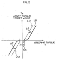
- Fig. 2 is a diagram for explaining the basic assist characteristic corresponding to the basic assist map stored in the assist characteristic storage section 22, and the modified assist characteristic prepared by shifting the basic assist characteristic along the steering torque coordinate axis.
- the steering torque T detected by the torque sensor 5 has a positive value when the torque is applied to the steering wheel 1 for rightward steering, and has a negative value when the torque is applied to the steering wheel 1 for leftward steering.
- the basic assist characteristic is indicated by a curve L0 in Fig. 2 .
- the basic assist characteristic is determined so that a positive assist torque target value Ta corresponds to a positive steering torque value T and a negative assist torque target value Ta corresponds to a negative steering torque value T.
- the plural basic assist maps for the plural vehicle speed ranges are stored in the assist characteristic storage section 22 as described above, only one basic assist characteristic for one vehicle speed range is shown in Fig. 2 for simplicity of the explanation.
- This steering torque range is a dead zone NS.
- the assist torque target value Ta is determined on the basis of the virtual modified assist characteristic (e.g., a characteristic indicated by curves L11, L12) prepared by shifting the basic assist characteristic along the steering torque coordinate axis (positively or negatively) by the shift amount ⁇ T computed by the shift amount computing section 24 on the basis of the steering angular speed ⁇ computed by the steering angular speed computing section 23, the vehicle speed V and the steering torque T.
- the virtual modified assist characteristic e.g., a characteristic indicated by curves L11, L12
- the basic assist characteristic is negatively shifted along the steering torque coordinate axis when the steering torque T is not smaller than zero (see the curve L11), and is positively shifted along the steering torque coordinate axis when the steering torque T has a negative value (see the curve L12) .
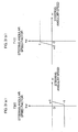
- Figs. 3(a) and 3(b) are diagrams illustrating relationships between the steering angular speed factor k ⁇ and the steering angular speed ⁇ .
- the shift amount computing section 24 has a memory which stores tables, for example, for the characteristic curves (broken lines in this case) shown in Figs. 3(a) and 3(b) .
- the shift amount computing section 24 determines the steering angular speed factor k ⁇ on the basis of the table of the characteristic shown in Fig. 3 (a) when the steering torque T is T ⁇ 0, and determines the steering angular speed factor k ⁇ on the basis of the table of the characteristic shown in Fig. 3(b) when the steering torque T is T ⁇ 0.
- the steering angular speed factor k ⁇ is set at zero or a positive value when the steering angular speed ⁇ is in a range not smaller than a second predetermined value ⁇ 2 ( ⁇ 2 ⁇ 0, e.g.,
- the basic shift amount ⁇ T B is zero.
- the basic shift amount ⁇ T B is determined so that the basic assist characteristic is shifted toward the origin along the steering torque coordinate axis.
- the basic shift amount ⁇ T B is determined so that the basic assist characteristic is shifted toward the origin along the steering torque coordinate axis.
- the basic assist characteristic Since the basic assist characteristic is not shifted in the forward stroke steering, the steering burden does not vary according to the steering angular speed. Therefore, the basic assist characteristic can easily be tuned, and a sufficient steering response can be provided to the driver. In the return stroke steering operation and the steering holding operation, the basic assist characteristic is shifted toward the origin, whereby the spring feeling can be eliminated in the return stroke steering operation and the steering burden can be alleviated in the steering holding operation. Thus, a comfortable steering feeling can be ensured.
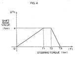
- Fig. 4 is a diagram for explaining a relationship between the shift base value ⁇ T 0 and the absolute value
- the shift amount computing section 24 has a memory which stores a table, for example, for a characteristic curve (broken line) as shown in Fig. 4 .
- is divided by a first threshold value T1 (e.g., 4 (Nm)), a second threshold value T2 (e.g., 5 (Nm)) and a third threshold value T3 (e.g., 6 (Nm)).
- T1 e.g., 4 (Nm)
- T2 e.g., 5 (Nm)
- T3 e.g., 6 (Nm)
- the shift base value ⁇ T 0 is determined so as to be linearly reduced from the upper limit ⁇ to zero.
- the basic shift amount ⁇ T B is determined on the basis of the characteristic specified for the range of 0 ⁇
- is relatively great in a range of T2 ⁇
- the absolute value of the basic shift amount ⁇ T B is reduced as the steering torque absolute value
- Fig. 5 is a diagram for explaining the variable setting of the shift amount ⁇ T for the vehicle speed V
- Fig. 6 is a diagram for explaining the variable setting of the shift amount ⁇ T for the steering torque T.
- the shift amount computing section 24 determines the steering angular speed factor k ⁇ and the shift base value ⁇ T 0 on the basis of the characteristics shown in Figs. 3 (a) , 3 (b) and 4, and determines the basic shift amount ⁇ T B on the basis of the steering angular speed factor k ⁇ and the shift base value ⁇ T 0 .
- the assist torque target value determining section 21 searches the basic assist map stored in the assist characteristic storage section 22 on the basis of the shift amount ⁇ T.
- the assist torque target value Ta is read out according to the modified assist characteristic virtually determined on the basis of the steering angular speed ⁇ , the vehicle speed V and the steering torque T.
- the vehicle speed gain G v is determined so as to be increased monotonously (linearly in this case) to a predetermined upper limit (an upper limit of 1 in Fig. 5 ) as the vehicle speed V increases in a range from zero to a predetermined vehicle speed.
- the steering operation can properly be performed even if little modification to the assist characteristic is required, for example, when the vehicle is at a stop or travels at a low speed.
- the assist torque target value Ta is determined according to the virtual modified assist characteristic prepared by shifting the basic assist characteristic by the shift amount ⁇ T along the steering torque coordinate axis.
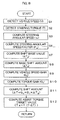
- Fig. 7 is a flow chart for explaining a processing operation to be performed repeatedly in a predetermined control cycle by the microprocessor 20.
- the microprocessor 20 reads a vehicle speed V detected by the vehicle speed sensor 6 and a steering torque T detected by the torque sensor 5 (Steps S1, S2). Further, the steering angular speed computing section 23 reads an output signal of the steering angle sensor 7, and determines a steering angular speed ⁇ (Step S3) . On the basis of the steering angular speed ⁇ thus determined, the shift amount computing section 24 reads a steering angular speed factor k ⁇ for the steering angular speed ⁇ (Step S4) . Then, the shift amount computing section 24 judges whether the forward stroke steering is performed (Step S5).
- Step S6 If it is judged for the first time that the steering holding operation or the return stroke steering operation is performed after the judgment of the forward stroke steering (YES in Step S6), the steering torque T (Step S2) detected in this control cycle is referred to, and a shift base value ⁇ T 0 (see Fig. 4 ) for the steering torque T is determined (Step S7). Thereafter, the shift base value ⁇ T 0 is kept unchanged as long as it is continuously judged that the steering holding operation or the return stroke steering operation is performed (NO in Step S6). During the steering holding operation or the return stroke steering operation, the shift base value ⁇ T 0 is kept at a value corresponding to the steering torque T detected immediately after the switching from the forward stroke steering to the steering holding operation or to the return stroke steering operation.
- the shift amount ⁇ T thus determined is applied to the assist torque target value determining section 21.
- an assist torque target value Ta is read out of the assist characteristic storage section 22 according to a virtual modified assist characteristic prepared by shifting the basic assist characteristic by the shift amount ⁇ T along the steering torque coordinate axis.
- the motor driver 30 is controlled, so that a driving force correspondingly generated by the motor M is applied to the steering mechanism 3.
- Fig. 8 is a flow chart for explaining a processing operation to be performed in an electric power steering apparatus according to a second embodiment of the present invention.
- Figs. 1 to 6 steps corresponding to those shown in Fig. 7 will be denoted by the same reference characters as in Fig. 7 .
- Steps S5 and S6 are omitted, so that the shift base value ⁇ T 0 varies on a real-time basis according to the steering torque T detected in every control cycle.
- the shift amount is variably set according to the steering force in the steering holding operation and in the return stroke steering operation. Therefore, the steering feeling can further be improved.
- the shift amount ⁇ T may be determined by multiplying the basic shift amount ⁇ T B by the torque gain G T alone without the use of the vehicle gain Gv.
- the basic shift amount ⁇ T B may be employed as the shift amount ⁇ T without the use of the vehicle gain G v and the torque gain G T .
- the shift amount ⁇ T may be determined by multiplying the basic shift amount ⁇ T B by the vehicle gain G v alone without the use of the torque gain G T .
- the torque gain G T and the shift base value ⁇ T 0 may be employed in combination to provide a map indicating a relationship between the steering torque T and G T ⁇ T 0 .
- the assist map for the basic assist characteristic is stored in the assist characteristic storage section 22, and the assist torque target value Ta is read out of the assist map.
- the assist torque target value Ta for the search-oriented steering torque value T* may be determined by function-based computation.
- the shift amount computing section 24 may be adapted to preliminarily store the characteristic of the steering angular speed factor k ⁇ for the steering angular speed ⁇ and the characteristic of the shift base value ⁇ T 0 for the steering torque T in a memory thereof, or may be adapted to determine the steering angular speed factor k ⁇ for the steering angular speed ⁇ and the shift base value ⁇ T 0 for the steering torque T by function-based computation.
- the determination of the vehicle gain G v for the vehicle speed V and the torque gain G T for the steering torque T may be achieved in the same manner.
- the assist torque target value is defined as the motor driving target value
- the characteristic of the assist torque target value for the steering torque is defined as the assist characteristic.
- the present invention is not limited to this arrangement.
- Amotor current target value or a motor voltage target value may be defined as the motor driving target value
- a relationship between the steering torque and the motor current target value or the motor voltage target value may be defined as the assist characteristic.
- the steering angular speed is computed by time-based differentiation of the steering angle detected by the steering angle sensor 7.
- a brush motor is adopted as the electric motor M
- a counter-electromotive force to be generated between terminals of the electric motor M may be determined on the basis of an output of a motor current detection circuit which determines a motor current of the electric motorM and an output of an inter-terminal voltage detection circuit which detects an inter-terminal voltage of the electric motor M
- the steering angular speed may be estimated on the basis of the counter-electromotive force without the use of the steering angle sensor.
- a brushless motor may be adopted as the electric motor M.
- the output of a resolver associated with the brushless motor may be used to calculate the steering angular speed without the use of the steering angle sensor.
- a motor mechanical angle is calculated based on the output of the resolver, and the motor angular speed is calculated by time-based differentiation of the motor mechanical angle.
- the motor angle speed is then converted in terms of the steering shaft to obtain the steering angular speed.
Landscapes
- Engineering & Computer Science (AREA)
- Chemical & Material Sciences (AREA)
- Combustion & Propulsion (AREA)
- Transportation (AREA)
- Mechanical Engineering (AREA)
- Steering Control In Accordance With Driving Conditions (AREA)
- Power Steering Mechanism (AREA)
Description
- The present invention relates to an electric power steering apparatus which is adapted to transmit a driving force generated as a steering assist force by an electric motor to a steering mechanism.
- Electric power steering apparatuses are conventionally used, which are adapted to transmit a driving force generated by an electric motor to a steering mechanism via a gear mechanism (reduction gear mechanism) or by a direct drive system.
- In such an electric power steering apparatus, an assist characteristic which defines a relationship between a steering torque applied to a steering wheel and a target value of an assist torque to be applied to the steering mechanism from the electric motor is preliminarily determined, and stored as an assist map in a memory. An assist torque target value for a given steering torque is read out of the assist map. The electric motor is controlled to be driven on the basis of the assist torque target value thus read out.
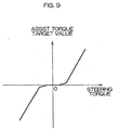
- As shown in
Fig. 9 , the assist characteristic is defined so that the assist torque target value is increased as the steering torque increases. For example, the steering torque is assigned a positive value for rightward steering, and assigned a negative value for leftward steering. The assist characteristic is defined so that a positive assist torque target value corresponds to a positive steering torque value and a negative assist torque target value corresponds to a negative steering torque value. - When the assist torque target value is positive, the steering assist force acts on the steering mechanism for turning steerable wheels rightward. When the assist torque target value is negative, on the other hand, the steering assist force acts on the steering mechanism for turning the steerable wheels leftward. Where the steering torque has a value within a dead zone around zero, the assist torque target value is set at zero.
- The electric power steering apparatus employing the assist characteristic is problematic in that, when a driver performs a return stroke steering operation to turn the steering wheel back to a steering angle midpoint, the driver is liable to have a heavier steering feeling (so-called "spring feeling") such that the steering wheel is returned to the steering angle midpoint more heavily than intended by the driver. That is, the steering torque is reduced in the return stroke steering operation, so that the assist force is correspondingly reduced. Therefore, the steering wheel receives a reverse input from the wheels thereby to be heavily returned to the steering angle midpoint.
- Further, the electric power steering apparatus is problematic in that, when the driver performs a steering holding operation to hold the steering wheel at a certain steering angle, a steering burden is increased.
- These problems can be solved by increasing the inclination of an assist characteristic curve so that the assist torque target value is set greater for a given steering torque. In this case, however, a steering response is reduced when the driver performs a forward stroke steering to actively turn the steering wheel.
- The aforesaid problems are solved by an arrangement proposed in
EP 1 452 421 A1 - Thus, a sufficient steering response can be provided in the forward stroke steering. Further, a sufficient steering assist force is transmitted to the steering mechanism in the return stroke steering operation, thereby eliminating the unwanted heavier steering feeling (spring feeling) such that the steering wheel is returned to the steering angle midpoint more heavily than intended by the driver. In the steering holding operation, the steering burden can be alleviated.
- With the arrangement according to the prior application, however, the shift amount employed in the steering holding operation and the return stroke steering operation is constant irrespective of the steering burden applied before or after the return stroke steering operation or in the steering holding operation. Therefore, the driver is liable to have an uncomfortable steering feeling. Particularly, when a U-turn steering operation is performed, the steering wheel is turned by a greater steering angle, then held at the steering angle for a short period of time, and turned back. In the last half of the U-turn steering operation (in the instance of the switching from the short-period steering holding operation to the return stroke steering operation), the steering burden is suddenly reduced. This is the cause of the uncomfortable steering feeling.
- It is therefore an object of the present invention to provide an electric power steering apparatus which eliminates the uncomfortable steering feeling to make the steering feeling comfortable.
- This object is achieved by an electric power steering apparatus according to
claim 1, which transmits a driving force of an electric motor to a steering mechanism for steering assist and comprises : a torque sensor which detects a steering torque applied to an operation member for steering a vehicle; a basic assist characteristic determining section which determines a basic assist characteristic defining a basic characteristic of a motor driving target value for the steering torque detected by the torque sensor; a motor driving target value determining section which determines the motor driving target value for the steering torque detected by the torque sensor in accordance with a modified assist characteristic prepared by shifting the basic assist characteristic determined by the basic assist characteristicdeterminingsectionalongasteeringtorque coordinate axis; a shift amount determining section which determines the amount of the shift from the basic assist characteristic to the modified assist characteristic on the basis of the steering torque detected by the torque sensor; and a motor driving section which drives the electric motor on the basis of the motor driving target value determined by the motor driving target value determining section. - According to the present invention, the modified assist characteristic prepared by modifying the basic assist characteristic determined by the basic assist characteristic determining section is employed for the determination of the motor driving target value for the steering torque detected by the torque sensor. That is, the motor driving target value is determined on the basis of the modified assist characteristic.
- The modification of the basic assist characteristic is achieved by shifting the basic assist characteristic along the steering torque coordinate axis, and the shift amount is determined on the basis of the steering torque. Thus, the shift amount is properly determined according to the level of a steering burden, so that an uncomfortable steering feeling can be eliminated. Therefore, a comfortable steering feeling can be ensured.
- The shift amount determining section preferably determines the shift amount so that the absolute value of the shift amount is reduced as the absolute value of the steering torque increases in a range greater than a predetermined threshold value (e.g., a lower limit of a torque value detected when a steering angle is great as in the U-turn steering operation). Thus, the absolute value of the shift amount is minimized, for example, in the U-turn steering operation. Therefore, the uncomfortable steering feeling can effectively be suppressed without sudden reduction of the steering force.
- The shift amount determining section preferably sets the amount of the shift from the basic assist characteristic to the modified assist characteristic at zero in the forward stroke steering where the operation member is operated apart from a steering angle midpoint. Further, the shift amount determining section preferably sets the amount of the shift from the basic assist characteristic to the modified assist characteristic at a value such that the motor driving target value for the steering torque detected by the torque sensor has an increased absolute value in the modified assist characteristic in the steering holding operation and in the return stroke steering operation where the operation member is operated toward the steering angle midpoint.
- With this arrangement, the shift amount is set at zero in the forward stroke steering (where the operation member is operated apart from the steering angle midpoint), and is determined so that the motor driving target value has a greater absolute value in the modified assist characteristic than in the basic assist characteristic in the steering holding operation and in the return stroke steering operation (where the operation member is operated toward the steering angle midpoint).
- More specifically, a steering speed detecting section which detects the steering speed of the operation member is provided, and a shift direction and a shift amount of the basic assist characteristic are variably set according to the direction (equal to the steering direction) and the absolute value of the steering speed detected by the steering speed detecting section. For example, it is herein assumed that the steering torque detected by the torque sensor has a positive value for rightward steering and has a negative value for leftward steering, and the motor driving target value is assigned a positive value for the positive steering torque value and assigned a negative value for the negative steering torque value in the basic assist characteristic. Further, it is assumed that the steering speed has a positive value for the rightward steering and has a negative value for the leftward steering.
- With a steering torque value of not smaller than zero, for example, the shift amount is set at zero when the steering speed has a positive value not smaller than a first predetermined value (in the forward stroke steering), and is determined according to the steering speed when the steering speed has a value smaller than the first predetermined value. At this time, it is merely necessary to shift the basic assist characteristic negatively along the steering torque coordinate axis, but not positively along the steering torque coordinate axis. That is, the shift amount may be set at zero when the steering speed is at the first predetermined value, and determined so as to be reduced monotonously (stepwise or linearly) to a negative lower limit as the steering speed decreases when the steering speed is lower than the first predetermined value. Thus, the basic assist characteristic is shifted toward the origin in a positive steering torque range, so that the steering assist force is increased to eliminate the spring feeling occurring in the return stroke steering operation. The first predetermined value should be not smaller than zero. If the first predetermined value is a positive value, the steering assist force can be increased in the steering holding operation where the steering speed is virtually zero. Therefore, the steering burden on the driver can be alleviated in the steering holding operation. In the return stroke steering operation where the steering speed has a negative value, the shift amount may variably be set according to the steering speed, or may be fixed at the negative lower limit irrespective of the steering speed.
- With a negative steering torque value, the shift amount is set at zero when the steering speed has a negative value not greater than a second predetermined value, and is determined according to the steering speed when the steering speed has a value greater than the second predetermined value. At this time, it is merely necessary to shift the basic assist characteristic positively along the steering torque coordinate axis but not negatively along the steering torque coordinate axis. That is, the shift amount may be set at zero when the steering speed is at the second predetermined value, and determined so as to be increased monotonously (stepwise or linearly) to a positive upper limit as the steering speed increases when the steering speed is higher than the second predetermined value. Thus, the basic assist characteristic is shifted toward the origin in a negative steering torque range, so that the steering assist force is increased to eliminate the spring feeling occurring in the return stroke steering operation. The second predetermined value should be not greater than zero. If the second predetermined value is a negative value, the steering assist force can be increased in the steering holding operation where the steering speed is virtually zero. Therefore, the steering burden on the driver can be alleviated in the steering holding operation. In the return stroke steering operation where the steering speed has a positive value, the shift amount may variably be set according to the steering speed, or may be fixed at the positive upper limit irrespective of the steering speed.
- The motor driving target value is determined on the basis of the modified assist characteristic thus prepared, so that the assist characteristic can be determined differently between the forward stroke steering and the return stroke steering operation. Thus, a sufficient steering response can be provided in the forward stroke steering, and a sufficient steering assist force is transmitted to the steering mechanism in the return stroke steering operation , thereby eliminating an unwanted heavier steering feeling (spring feeling) such that the steering wheel is returned to the midpoint more heavily than intended by the driver. In addition, the same basic assist map is employed in the forward stroke steering, so that the steering burden does not vary according to the steering speed. Therefore, the basic assist map can easily be tuned.
- The electric power steering apparatus described above may further comprise: a vehicle speed sensor which detects the traveling speed of the vehicle mounted with the electric power steering apparatus; and a vehicle speed adaptive shift amount determining section which variably sets the amount of the shift from the basic assist characteristic to the modified assist characteristic according to the vehicle speed detected by the vehicle speed sensor.
- With this arrangement, the shift amount of the basic assist characteristic is variably set according to the vehicle speed. Therefore, the steering operation can properly be performed even if little modification to the assist characteristic is required, for example, when the vehicle is at a stop or travels at a low speed.
- The shift amount determining section preferably computes the shift amount for the steering holding operation and the return stroke steering operation on the basis of a steering torque detected by the torque sensor when the forward stroke steering is switched to the steering holding operation or to the return stroke steering operation (immediately before or after the switching of the steering operation).
- With this arrangement, the shift amount is determined on the basis of the steering torque detected when the forward stroke steering is switched to the steering holding operation or to the return stroke steering operation. Therefore, the steering assist can properly be achieved according to the steering burden in the steering holding operation and in the return stroke steering operation, thereby providing a comfortable steering feeling. In the steering holding operation and the return stroke steering operation, a processing operation to be performed by a control unit can be simplified to alleviate a computation load on the control unit as compared with a case where the shift amount is variably set according to a steering torque constantly detected on a real-time basis.
- The foregoing and other objects, features and effects of the present invention will become more apparent from the following description of the preferred embodiments with reference to the attached drawings.
-
Fig. 1 is a block diagram illustrating the electrical construction of an electric power steering apparatus according to one embodiment of the present invention; -
Fig. 2 is a diagram for explaining a basic assist characteristic and a modified assist characteristic prepared by shifting the basic assist characteristic along a steering torque coordinate axis; -
Figs. 3(a) and 3(b) are diagrams illustrating relationships between a steering angular speed factor and a steering angular speed; -
Fig. 4 is a diagram illustrating a relationship between a shift base value and the absolute value of a steering torque; -
Fig. 5 is a diagram for explaining the variable setting of a shift amount for a vehicle speed; -
Fig. 6 is a diagram for explaining the variable setting of the shift amount for the steering torque; -
Fig. 7 is a flow chart for explaining a processing operation to be performed repeatedly in a predetermined control cycle by a microprocessor for controlling the driving of an electric motor; -
Fig. 8 is a flow chart for explaining a processing operation to be performed by a microprocessor according to a second embodiment of the present invention; and -
Fig. 9 is a diagram illustrating an exemplary assist characteristic. -
Fig. 1 is a block diagram illustrating the electrical construction of an electric power steering apparatus according to one embodiment of the present invention. A steering torque applied to asteering wheel 1 as an operation member is mechanically transmitted to asteering mechanism 3 including a rack shaft via asteering shaft 2. A steering assist force is mechanically transmitted to thesteering mechanism 3 from an electric motor M via a driving force transmission mechanism such as a gear mechanism (reduction gear mechanism) or by a direct drive system. - The steering
shaft 2 is divided into aninput shaft 2A coupled to thesteering wheel 1 and anoutput shaft 2B coupled to thesteering mechanism 3. Theinput shaft 2A and theoutput shaft 2B are coupled to each other by atorsion bar 4. Thetorsion bar 4 is distorted according to the steering torque, and the direction and amount of the distortion is detected by atorque sensor 5. - The
torque sensor 5 is, for example, of a magnetic type, which is adapted to detect a magnetic resistance varying according to a rotational positional relationship between theinput shaft 2A and theoutput shaft 2B. An output signal of thetorque sensor 5 is inputted to a controller 10 (ECU: electronic control unit). - An output signal of a
vehicle speed sensor 6 which detects the traveling speed of a vehicle mounted with the electric power steering apparatus and an output signal of a steering angle sensor 7 which detects the steering angle of the steering wheel 1 (e.g., the rotation angle of theinput shaft 2A) are inputted to thecontroller 10. - The
controller 10 determines a target value of an assist torque to be applied to thesteering mechanism 3 from the electric motor M according to a steering speed determined on the basis of the steering torque detected by thetorque sensor 5, the vehicle speed detected by thevehicle speed sensor 6 and the output of the steering angle sensor 7, and controls the driving of the electric motor M so as to apply the steering assist force to thesteering mechanism 3 according to the steering torque and the like. - The
controller 10 includes amicroprocessor 20, and amotor driver 30 which drives the electric motor M on the basis of a control signal applied from themicroprocessor 20. - The
microprocessor 20 includes an assist torque targetvalue determining section 21 as a functional processing section implemented by program-based processing, and an assistcharacteristic storage section 22 constituted by a storage area of a memory in themicroprocessor 20. The assistcharacteristic storage section 22 stores a plurality of basic assist maps for plural basic assist characteristics preliminarily determined for plural vehicle speed ranges. The basic assist characteristics each define a basic characteristic of the assist torque target value for the steering torque. Base values for the assist torque target value are stored in association with plural steering torque values in the form of an assist map (table) in the assistcharacteristic storage section 22. - The
microprocessor 20 further includes a steering angularspeed computing section 23 which computes a steering angular speed on the basis of the output signal of the steering angle sensor 7, and a shiftamount computing section 24 which computes a shift amount to be employed for preparing a virtual modified assist characteristic by shifting the basic assist characteristic along a steering torque coordinate axis. The shiftamount computing section 24 computes the shift amount on the basis of the steering angular speed ω computed by the steering angularspeed computing section 23, the vehicle speed V detected by thevehicle speed sensor 6 and the steering torque T detected by thetorque sensor 5 for preparing the virtual modified assist characteristic by shifting the basic assist characteristic along the steering torque coordinate axis. - The assist torque target
value determining section 21 reads out an assist torque target value Ta for the modified assist characteristic from the assistcharacteristic storage section 22 on the basis of the steering torque T detected by thetorque sensor 5, the vehicle speed V detected by thevehicle speed sensor 6 and the shift amount ΔT (whose sign indicates a shift direction and whose absolute value indicates a shift distance) computed by the shiftamount computing section 24. Themotor driver 30 supplies a necessary and sufficient driving current to the electric motor M on the basis of the assist torque target value Ta thus read out. -
Fig. 2 is a diagram for explaining the basic assist characteristic corresponding to the basic assist map stored in the assistcharacteristic storage section 22, and the modified assist characteristic prepared by shifting the basic assist characteristic along the steering torque coordinate axis. - The steering torque T detected by the
torque sensor 5 has a positive value when the torque is applied to thesteering wheel 1 for rightward steering, and has a negative value when the torque is applied to thesteering wheel 1 for leftward steering. The basic assist characteristic is indicated by a curve L0 inFig. 2 . The basic assist characteristic is determined so that a positive assist torque target value Ta corresponds to a positive steering torque value T and a negative assist torque target value Ta corresponds to a negative steering torque value T. Although the plural basic assist maps for the plural vehicle speed ranges are stored in the assistcharacteristic storage section 22 as described above, only one basic assist characteristic for one vehicle speed range is shown inFig. 2 for simplicity of the explanation. - In the basic assist characteristic indicated by the curve L0, the assist torque target value Ta is set at Ta=0 irrespective of the steering torque value T in a steering torque range around T=0. This steering torque range is a dead zone NS.
- In this embodiment, the assist torque target value Ta is determined on the basis of the virtual modified assist characteristic (e.g., a characteristic indicated by curves L11, L12) prepared by shifting the basic assist characteristic along the steering torque coordinate axis (positively or negatively) by the shift amount ΔT computed by the shift
amount computing section 24 on the basis of the steering angular speed ω computed by the steering angularspeed computing section 23, the vehicle speed V and the steering torque T. - As will be described later, the basic assist characteristic is negatively shifted along the steering torque coordinate axis when the steering torque T is not smaller than zero (see the curve L11), and is positively shifted along the steering torque coordinate axis when the steering torque T has a negative value (see the curve L12) .
- The shift
amount computing section 24 determines a basic shift amount ΔTB on the basis of the steering torque T and the steering angular speed ω, and determines the shift amount ΔT (=GV×GT×ΔTB) by multiplying the basic shift amount ΔTB by a vehicle speed gain Gv and a torque gain GT to be described later. - The basic shift amount ΔTB (=ΔT0×kω) is determined on the basis of a factor (steering angular speed factor) kω dependent on the steering angular speed ω and a shift base value ΔT0 (ΔT0≥0) dependent on a steering torque T sampled immediately after the steering is switched from a forward stroke steering to a steering holding operation or to a return stroke steering operation.
-
Figs. 3(a) and 3(b) are diagrams illustrating relationships between the steering angular speed factor kω and the steering angular speed ω. The shiftamount computing section 24 has a memory which stores tables, for example, for the characteristic curves (broken lines in this case) shown inFigs. 3(a) and 3(b) . The shiftamount computing section 24 determines the steering angular speed factor kω on the basis of the table of the characteristic shown inFig. 3 (a) when the steering torque T is T≥0, and determines the steering angular speed factor kω on the basis of the table of the characteristic shown inFig. 3(b) when the steering torque T is T<0. - In the table of the characteristic of
Fig. 3 (a) to be employed when T≥0, the steering angular speed factor kω is set at zero or a negative value when the steering angular speed ω is in a range not greater than a first predetermined value ω1 (>0). More specifically, the steering angular speed factor kω is determined so as to be reduced monotonously (linearly inFig. 3(a) ) to a predetermined lower limit (a lower limit of -1 inFig. 3(a) ) as the steering angular speed ω decreases in the range not greater than the first predetermined value ω1. On the contrary, when the steering angular speed ω is greater than the first predetermined value ω1, the steering angular speed factor kω is set at kω=0 irrespective of the steering angular speed ω - In the table of the characteristic of
Fig. 3 (b) to be employed when T<0, the steering angular speed factor kω is set at zero or a positive value when the steering angular speed ω is in a range not smaller than a second predetermined value ω2 (ω2<0, e.g., |ω2| = ω1). More specifically, the steering angular speed factor kω is determined so as to be increased monotonously (linearly inFig. 3(b) ) to a predetermined upper limit (an upper limit of 1 inFig. 3(b) ) as the steering angular speed ω increases in the range not smaller than the second predetermined value ω2. On the contrary, when the steering angular speed ω is smaller than the second predetermined value ω2, the steering angular speed factor kω is set at kω=0 irrespective of the steering angular speed ω. - In the forward stroke steering (for turning the steering wheel apart from a steering angle midpoint) where the direction of the steering torque T coincides with the direction of the steering angular speed ω, the basic shift amount ΔTB is zero. In the return stroke steering operation (for turning the steering wheel toward the steering angle midpoint) where the direction of the steering torque T does not coincide with the direction of the steering angular speed ω, the basic shift amount ΔTB is determined so that the basic assist characteristic is shifted toward the origin along the steering torque coordinate axis. When the steering angular speed ω has a value around zero (ω2<ω<ω1), the basic shift amount ΔTB is determined so that the basic assist characteristic is shifted toward the origin along the steering torque coordinate axis.
- Since the basic assist characteristic is not shifted in the forward stroke steering, the steering burden does not vary according to the steering angular speed. Therefore, the basic assist characteristic can easily be tuned, and a sufficient steering response can be provided to the driver. In the return stroke steering operation and the steering holding operation, the basic assist characteristic is shifted toward the origin, whereby the spring feeling can be eliminated in the return stroke steering operation and the steering burden can be alleviated in the steering holding operation. Thus, a comfortable steering feeling can be ensured.
-
Fig. 4 is a diagram for explaining a relationship between the shift base value ΔT0 and the absolute value |T| of the steering torque T sampled immediately after the switching from the forward stroke steering to the steering holding operation or to the return stroke steering operation. The shiftamount computing section 24 has a memory which stores a table, for example, for a characteristic curve (broken line) as shown inFig. 4 . - In
Fig. 4 , the range of the steering torque absolute value |T| is divided by a first threshold value T1 (e.g., 4 (Nm)), a second threshold value T2 (e.g., 5 (Nm)) and a third threshold value T3 (e.g., 6 (Nm)). In a range of 0≤|T|≤T1, the shift base value ΔT0 is determined so as to be linearly increased to an upper limit α (e.g., α=0.5Nm) as the steering torque absolute value |T| increases. In a range of T1< |T|≤T2, the shift base value ΔT0 is set at ΔT0=α irrespective of the steering torque absolute value |T|. In a range of T2< |T| ≤T3, the shift base value ΔT0 is determined so as to be linearly reduced from the upper limit α to zero. In a range of T3<|T|, the shift base value ΔT0 is set at ΔT0=0 irrespective of the steering torque absolute value |T|. - Since the basic shift amount ΔTB is determined on the basis of the characteristic specified for the range of 0≤|T|≤T1 according to the steering burden in the steering holding operation or in the return stroke steering operation, the uncomfortable steering feeling can be minimized. Thus, a comfortable steering feeling can be ensured.
- Immediately after the switching to the steering holding operation in the U-turn steering operation where the steering angle is great, the steering torque absolute value |T| is relatively great in a range of T2<|T|. In this situation, the absolute value of the basic shift amount ΔTB is reduced as the steering torque absolute value |T| increases. This prevents a phenomenon such that the steering assist force is suddenly reduced in the last half of the steering operation. Therefore, the uncomfortable steering feeling can be prevented.
-
Fig. 5 is a diagram for explaining the variable setting of the shift amount ΔT for the vehicle speed V, andFig. 6 is a diagram for explaining the variable setting of the shift amount ΔT for the steering torque T. The shiftamount computing section 24 determines the steering angular speed factor kω and the shift base value ΔT0 on the basis of the characteristics shown inFigs. 3 (a) , 3 (b) and 4, and determines the basic shift amount ΔTB on the basis of the steering angular speed factor kω and the shift base value ΔT0. Further, the shiftamount computing section 24 determines the shift amount ΔT (=ΔTB × Gv×GT) by multiplying the basic shift amount ΔTB by the vehicle speed gain Gv determined on the basis of the characteristic shown inFig. 5 and the torque gain GT determined on the basis of the characteristic shown inFig. 6 . The assist torque targetvalue determining section 21 searches the basic assist map stored in the assistcharacteristic storage section 22 on the basis of the shift amount ΔT. Thus, the assist torque target value Ta is read out according to the modified assist characteristic virtually determined on the basis of the steering angular speed ω, the vehicle speed V and the steering torque T. - - The vehicle speed gain Gv is determined so as to be increased monotonously (linearly in this case) to a predetermined upper limit (an upper limit of 1 in
Fig. 5 ) as the vehicle speed V increases in a range from zero to a predetermined vehicle speed. - Thus, the steering operation can properly be performed even if little modification to the assist characteristic is required, for example, when the vehicle is at a stop or travels at a low speed.
- On the other hand, the torque gain GT has a dead zone around a steering torque T of T=0. Outside the dead zone, the torque gain GT is determined so as to be increased monotonously (linearly in this case) to a predetermined upper limit (an upper limit of 1 in this case) as the absolute value of the steering torque T increases. Thus, the steering assist is limited when the steering assist is not required with the steering torque T being around T=0.
- On the basis of the shift amount ΔT thus determined, the assist torque target value Ta is determined according to the virtual modified assist characteristic prepared by shifting the basic assist characteristic by the shift amount ΔT along the steering torque coordinate axis.
- More specifically, where the basic assist characteristic Ta is expressed by a function Ta=f(T), a steering torque value T* for the assist map search is determined by subtracting the shift amount ΔT from the steering torque T detected by the torque sensor 5 (i.e., T*=T-ΔT), and the basic assist map stored in the assist
characteristic storage section 22 is searched on the basis of the search-oriented steering torque value T*. Thus, the assist torque target value Ta (=f(T*)) canbe determined on the basis of the virtual modified assist characteristic. -
Fig. 7 is a flow chart for explaining a processing operation to be performed repeatedly in a predetermined control cycle by themicroprocessor 20. Themicroprocessor 20 reads a vehicle speed V detected by thevehicle speed sensor 6 and a steering torque T detected by the torque sensor 5 (Steps S1, S2). Further, the steering angularspeed computing section 23 reads an output signal of the steering angle sensor 7, and determines a steering angular speed ω (Step S3) . On the basis of the steering angular speed ω thus determined, the shiftamount computing section 24 reads a steering angular speed factor kω for the steering angular speed ω (Step S4) . Then, the shiftamount computing section 24 judges whether the forward stroke steering is performed (Step S5). Where the sign of the steering torque T coincides with the sign of the steering angular speed ω, for example, it is judged that the forward stroke steering is performed. Otherwise, it is judged that the forward stroke steering is not performed (but the steering holding operation or the return stroke steering operation is performed). - If it is judged for the first time that the steering holding operation or the return stroke steering operation is performed after the judgment of the forward stroke steering (YES in Step S6), the steering torque T (Step S2) detected in this control cycle is referred to, and a shift base value ΔT0 (see
Fig. 4 ) for the steering torque T is determined (Step S7). Thereafter, the shift base value ΔT0 is kept unchanged as long as it is continuously judged that the steering holding operation or the return stroke steering operation is performed (NO in Step S6). During the steering holding operation or the return stroke steering operation, the shift base value ΔT0 is kept at a value corresponding to the steering torque T detected immediately after the switching from the forward stroke steering to the steering holding operation or to the return stroke steering operation. - The shift
amount computing section 24 determines the basic shift amount ΔTB=ΔT0×kω on the basis of the shift base value ΔT0 thus determined (Step S8). Further, the shiftamount computing section 24 determines a vehicle speed gain Gv on the basis of the vehicle speed V detected by the vehicle speed sensor 6 (Step S9), and determines a torque gain GT on the basis of the steering torque T detected by the torque sensor 5 (Step S10) . Then, a shift amount ΔT is computed by multiplying the basic shift amount ΔTB by the vehicle speed gain Gv and the torque gain GT thus determined (Step S11). - The shift amount ΔT thus determined is applied to the assist torque target
value determining section 21. The assist torque targetvalue determining section 21 determines a search-oriented steering torque value T* (T*=T-ΔT), and searches the basic assist map stored in the assistcharacteristic storage section 22 on the basis of the search-oriented steering torque value T* (Step S12). - Thus, an assist torque target value Ta is read out of the assist
characteristic storage section 22 according to a virtual modified assist characteristic prepared by shifting the basic assist characteristic by the shift amount ΔT along the steering torque coordinate axis. On the basis of the assist characteristic target value Ta thus read out, themotor driver 30 is controlled, so that a driving force correspondingly generated by the motor M is applied to thesteering mechanism 3. -
Fig. 8 is a flow chart for explaining a processing operation to be performed in an electric power steering apparatus according to a second embodiment of the present invention. For the explanation of the second embodiment, reference will be made again toFigs. 1 to 6 . InFig. 8 , steps corresponding to those shown inFig. 7 will be denoted by the same reference characters as inFig. 7 . - In this embodiment, Steps S5 and S6 are omitted, so that the shift base value ΔT0 varies on a real-time basis according to the steering torque T detected in every control cycle. Thus, the shift amount is variably set according to the steering force in the steering holding operation and in the return stroke steering operation. Therefore, the steering feeling can further be improved.
- While the embodiments of the present invention have thus been described, the invention may be embodied in any other ways. Although the vehicle speed V is taken into consideration for the determination of the shift amount ΔT of the assist characteristic in the embodiments described above, the variable setting of the shift amount depending on the vehicle speed V is not necessarily required. That is, the shift amount ΔT may be determined by multiplying the basic shift amount ΔTB by the torque gain GT alone without the use of the vehicle gain Gv. Alternatively, the basic shift amount ΔTB may be employed as the shift amount ΔT without the use of the vehicle gain Gv and the torque gain GT. Further, the shift amount ΔT may be determined by multiplying the basic shift amount ΔTB by the vehicle gain Gv alone without the use of the torque gain GT.
- Further, the torque gain GT and the shift base value ΔT0 may be employed in combination to provide a map indicating a relationship between the steering torque T and GT×ΔT0.
- In the embodiments described above, the assist map for the basic assist characteristic is stored in the assist
characteristic storage section 22, and the assist torque target value Ta is read out of the assist map. However, the assist torque target value Ta for the search-oriented steering torque value T* may be determined by function-based computation. - Similarly, the shift
amount computing section 24 may be adapted to preliminarily store the characteristic of the steering angular speed factor kω for the steering angular speed ω and the characteristic of the shift base value ΔT0 for the steering torque T in a memory thereof, or may be adapted to determine the steering angular speed factor kω for the steering angular speed ω and the shift base value ΔT0 for the steering torque T by function-based computation. The determination of the vehicle gain Gv for the vehicle speed V and the torque gain GT for the steering torque T may be achieved in the same manner. - In the embodiments described above, the assist torque target value is defined as the motor driving target value, and the characteristic of the assist torque target value for the steering torque is defined as the assist characteristic. However, the present invention is not limited to this arrangement. Amotor current target value or a motor voltage target value may be defined as the motor driving target value, and a relationship between the steering torque and the motor current target value or the motor voltage target value may be defined as the assist characteristic.
- In the embodiments described above, the steering angular speed is computed by time-based differentiation of the steering angle detected by the steering angle sensor 7. However, where a brush motor is adopted as the electric motor M, a counter-electromotive force to be generated between terminals of the electric motor M may be determined on the basis of an output of a motor current detection circuit which determines a motor current of the electric motorM and an output of an inter-terminal voltage detection circuit which detects an inter-terminal voltage of the electric motor M, and the steering angular speed may be estimated on the basis of the counter-electromotive force without the use of the steering angle sensor.
- A brushless motor may be adopted as the electric motor M. In this case, the output of a resolver associated with the brushless motor may be used to calculate the steering angular speed without the use of the steering angle sensor. Specifically, a motor mechanical angle is calculated based on the output of the resolver, and the motor angular speed is calculated by time-based differentiation of the motor mechanical angle. The motor angle speed is then converted in terms of the steering shaft to obtain the steering angular speed.
- While the present invention has been described in detail by way of the embodiments thereof, it should be understood that the foregoing disclosure is merely illustrative of the technical principles of the present invention but not limitative of the same.
Claims (5)
- An electric power steering apparatus which transmits a driving force of an electric motor (M) to a steering mechanism (3) for steering assist, the apparatus comprising:a torque sensor (5) which detects a steering torque (T) applied to an operation member (1) for steering a vehicle;basic assist characteristic determining means (22) which determines a basic assist characteristic (LO) defining a basic characteristic of a motor driving target value (Ta) for the steering torque (T) detected by the torque sensor (5);motor driving target value determining means (21) which determines the motor driving target value (Ta) for the steering torque (T) detected by the torque sensor (5) in accordance with a modified assist characteristic (L11; L12) prepared by shifting the basic assist characteristic (LO) determined by the basic assist characteristic determining means (22) along a steering torque coordinate axis;shift amount determining means (24) which determines an amount (ΔT) of the shift from the basic assist characteristic (LO) to the modified assist characteristic (L11; L12) on the basis of the steering torque (T) detected by the torque sensor (5);motor driving means (20, 30) which drives the electric motor (M) on the basis of the motor driving target value determined by the motor driving target value determining means (21);wherein the shift amount determining means (24) determines the shift amount (ΔT) so that an absolute value of the shift amount is reduced as an absolute value (|T|) of the steering torque (T) increases in a range greater than a predetermined threshold value.
- The apparatus of claim 1, wherein the shift amount determining means (24) sets the amount (ΔT) of the shift from the basic assist characteristic (LO) to the modified assist characteristic (L11; L12) at zero in a forward stroke steering where the operation member (1) is operated apart from a steering angle midpoint, and sets the amount (ΔT) of the shift from the basic assist characteristic (LO) to the modified assist characteristic (L11; L12) at a value such that the motor driving target value for the steering torque detected by the torque sensor (5) has an increased absolute value in the modified assist characteristic (L11; L12) in a steering holding operation and in a return stroke steering operation where the operation member (1) is operated toward the steering angle midpoint.
- The apparatus of claim 1 or 2, wherein the shift amount determining means (24) computes the shift amount (ΔT) for the steering holding operation and the return stroke steering operation on the basis of the steering torque (T) detected by the torque sensor (5) when the forward stroke steering is switched to the steering holding operation or to the return stroke steering operation.
- The apparatus of any of claims 1 to 3, further comprising steering speed detecting means (23) which detects a steering speed (ω) of the operation member (1),
wherein the shift amount determining means (24) variably sets (S4, S8) a shift direction and a shift amount (ΔT) of the basic assist characteristic (LO) according to a direction and an absolute value of the steering speed (ω) detected by the steering speed detecting means (23). - The apparatus of any of claims 1 to 4, further comprising vehicle speed detecting means (6) which detects a traveling speed (V) of the vehicle mounted with the electric power steering apparatus,
wherein the shift amount determining means (24) comprises vehicle speed adaptive shift amount determining means (24) which variably sets (S9, S11) the amount (ΔT) of the shift from the basic assist characteristic (LO) to the modified assist characteristic (L11; L12) according to the vehicle speed (V) detected by the vehicle speed detecting means (6).
Applications Claiming Priority (2)
| Application Number | Priority Date | Filing Date | Title |
|---|---|---|---|
| JP2003315732A JP4411514B2 (en) | 2003-09-08 | 2003-09-08 | Electric power steering device |
| JP2003315732 | 2003-09-08 |
Publications (3)
| Publication Number | Publication Date |
|---|---|
| EP1512608A2 EP1512608A2 (en) | 2005-03-09 |
| EP1512608A3 EP1512608A3 (en) | 2005-12-21 |
| EP1512608B1 true EP1512608B1 (en) | 2008-03-12 |
Family
ID=34131941
Family Applications (1)
| Application Number | Title | Priority Date | Filing Date |
|---|---|---|---|
| EP04021195A Expired - Fee Related EP1512608B1 (en) | 2003-09-08 | 2004-09-07 | Electric power steering apparatus |
Country Status (5)
| Country | Link |
|---|---|
| US (1) | US7136732B2 (en) |
| EP (1) | EP1512608B1 (en) |
| JP (1) | JP4411514B2 (en) |
| CA (1) | CA2479716A1 (en) |
| DE (1) | DE602004012360T2 (en) |
Families Citing this family (26)
| Publication number | Priority date | Publication date | Assignee | Title |
|---|---|---|---|---|
| DE10117634A1 (en) * | 2001-04-09 | 2002-12-12 | Mercedes Benz Lenkungen Gmbh | Motorized power steering unit |
| JP4432709B2 (en) * | 2004-10-01 | 2010-03-17 | トヨタ自動車株式会社 | Electric power steering device |
| JP4579056B2 (en) * | 2005-06-02 | 2010-11-10 | 本田技研工業株式会社 | Vehicle steering system |
| JP4872298B2 (en) * | 2005-10-04 | 2012-02-08 | 日本精工株式会社 | Control device for electric power steering device |
| JP4895091B2 (en) * | 2006-01-16 | 2012-03-14 | 株式会社ジェイテクト | Electric power steering device |
| JP2008302900A (en) * | 2007-06-11 | 2008-12-18 | Nagoya Institute Of Technology | Control device for electric power steering device |
| US8452493B2 (en) * | 2008-01-25 | 2013-05-28 | Steering Solutions Ip Holding Corporation | Methods and systems involving return torque |
| FR2933660A3 (en) * | 2008-07-08 | 2010-01-15 | Renault Sas | Effort or mechanical action retrieving system operating method for steer by wire type electric steering system of motor vehicle, involves determining actions felt by driver when driver handles steering control element of steering system |
| JP5217794B2 (en) * | 2008-08-29 | 2013-06-19 | 株式会社ジェイテクト | Electric power steering device |
| JP5491721B2 (en) * | 2008-11-12 | 2014-05-14 | 本田技研工業株式会社 | Control device for electric power steering device |
| CN102105341B (en) * | 2009-01-28 | 2013-01-02 | 日本精工株式会社 | Electric power steering device |
| CN101858806B (en) * | 2009-04-07 | 2012-03-21 | 通用汽车环球科技运作公司 | Friction estimation and detection for electric power steering system |
| US8825295B2 (en) * | 2010-08-16 | 2014-09-02 | Honda Motor Co., Ltd. | System and method for determining a steering angle for a vehicle and system and method for controlling a vehicle based on same |
| KR20120020937A (en) * | 2010-08-31 | 2012-03-08 | 주식회사 만도 | Electric power steering apparatus |
| WO2012037951A2 (en) * | 2010-09-23 | 2012-03-29 | Thyssenkrupp Presta Ag | Driver assistance control in an electric steering system |
| JP5316599B2 (en) * | 2011-07-05 | 2013-10-16 | トヨタ自動車株式会社 | Steering device and steering control device |
| JP6180771B2 (en) * | 2013-03-29 | 2017-08-16 | 株式会社ジェイテクト | Electric power steering device |
| US9896122B2 (en) * | 2013-04-08 | 2018-02-20 | Mitsubishi Electric Corporation | Steering control device, and steering control method |
| CN104648469B (en) * | 2013-11-21 | 2017-11-14 | 联创汽车电子有限公司 | electric power steering torque controller |
| FR3019794B1 (en) * | 2014-04-10 | 2017-12-08 | Jtekt Europe Sas | ESTIMATING THE AGING OF AN ASSISTED DIRECTION |
| JP6020776B2 (en) * | 2014-08-08 | 2016-11-02 | 日本精工株式会社 | Electric power steering device |
| JP2016088436A (en) * | 2014-11-10 | 2016-05-23 | 株式会社デンソー | Motor control device |
| DE102016221500B4 (en) * | 2015-11-13 | 2020-02-27 | Denso Corporation | STEERING CONTROL |
| KR101736136B1 (en) * | 2015-12-07 | 2017-05-16 | 현대모비스 주식회사 | Motor driven power steering system and control method thereof |
| DE102019206980B4 (en) * | 2019-05-14 | 2023-06-22 | Volkswagen Aktiengesellschaft | Method and steering control device for determining a manipulated variable for setting a power steering torque in a vehicle steering system |
| DE102020110847A1 (en) * | 2020-04-21 | 2021-10-21 | Thyssenkrupp Ag | Method for determining the hysteresis and offset of a steering column torque determination |
Family Cites Families (14)
| Publication number | Priority date | Publication date | Assignee | Title |
|---|---|---|---|---|
| JP3493806B2 (en) * | 1995-04-21 | 2004-02-03 | 日本精工株式会社 | Control device for electric power steering device |
| JP3623022B2 (en) | 1995-08-24 | 2005-02-23 | ティーアールダブリュ オートモーティブ ジャパン株式会社 | Electric power steering device |
| JP3481468B2 (en) * | 1998-09-30 | 2003-12-22 | 三菱電機株式会社 | Electric power steering device |
| JP3663330B2 (en) * | 2000-02-29 | 2005-06-22 | 光洋精工株式会社 | Electric power steering device |
| JP3663332B2 (en) | 2000-03-15 | 2005-06-22 | 光洋精工株式会社 | Electric power steering control device |
| JP3698613B2 (en) | 2000-03-28 | 2005-09-21 | 光洋精工株式会社 | Electric power steering device |
| US6651771B2 (en) * | 2001-10-20 | 2003-11-25 | Ford Global Technologies, Llc | H-infinity control and gain scheduling method for electric power assist steering system |
| JP3868263B2 (en) * | 2001-10-29 | 2007-01-17 | 株式会社ジェイテクト | Power steering device |
| JP3947014B2 (en) * | 2002-01-25 | 2007-07-18 | 株式会社ジェイテクト | Electric power steering device |
| JP2004064858A (en) * | 2002-07-26 | 2004-02-26 | Honda Motor Co Ltd | Motor drive controller for electric power steering apparatus |
| JP4089367B2 (en) * | 2002-09-17 | 2008-05-28 | 株式会社ジェイテクト | Electric power steering device |
| JP3763472B2 (en) * | 2002-09-30 | 2006-04-05 | 三菱電機株式会社 | Electric power steering control device |
| JP4193113B2 (en) | 2003-02-27 | 2008-12-10 | 株式会社ジェイテクト | Electric power steering device |
| US6863150B1 (en) * | 2003-09-25 | 2005-03-08 | Mitsubishi Denki Kabushiki Kaisha | Electric power steering control apparatus |
-
2003
- 2003-09-08 JP JP2003315732A patent/JP4411514B2/en not_active Expired - Fee Related
-
2004
- 2004-08-26 CA CA002479716A patent/CA2479716A1/en not_active Abandoned
- 2004-08-27 US US10/927,528 patent/US7136732B2/en active Active
- 2004-09-07 EP EP04021195A patent/EP1512608B1/en not_active Expired - Fee Related
- 2004-09-07 DE DE602004012360T patent/DE602004012360T2/en active Active
Also Published As
| Publication number | Publication date |
|---|---|
| EP1512608A2 (en) | 2005-03-09 |
| EP1512608A3 (en) | 2005-12-21 |
| JP4411514B2 (en) | 2010-02-10 |
| JP2005081985A (en) | 2005-03-31 |
| CA2479716A1 (en) | 2005-03-08 |
| US7136732B2 (en) | 2006-11-14 |
| US20050061577A1 (en) | 2005-03-24 |
| DE602004012360D1 (en) | 2008-04-24 |
| DE602004012360T2 (en) | 2009-03-26 |
Similar Documents
| Publication | Publication Date | Title |
|---|---|---|
| EP1512608B1 (en) | Electric power steering apparatus | |
| EP1808360B1 (en) | Electric power steering apparatus | |
| US4865148A (en) | Vehicle height control apparatus responsive to power steering operation | |
| EP1077171B1 (en) | Electric power steering controller and control method thereof | |
| JP3685388B2 (en) | Vehicle steering control device | |
| EP2492169B1 (en) | Electric power steering apparatus | |
| US7051834B2 (en) | Power steering apparatus | |
| US6854560B2 (en) | Electric power steering apparatus | |
| US20050205344A1 (en) | Electrically driven power steering system for vehicle | |
| US5878360A (en) | Electric power steering control apparatus | |
| JP3593898B2 (en) | Steering control device | |
| EP1211160A1 (en) | Electric power steering system | |
| JP3974391B2 (en) | Control device for electric power steering device | |
| JP4161250B2 (en) | Electric power steering device | |
| JP3783621B2 (en) | Automatic steering device for vehicles | |
| CN113165691B (en) | Steering control system, steering control device, and steering control method | |
| JP3630280B2 (en) | Electric power steering device | |
| JP2004276805A (en) | Electric power steering device | |
| JP2005081986A (en) | Electric power steering device | |
| JP2004017898A (en) | Electric power steering device | |
| JPH10278818A (en) | Power steering device for vehicle | |
| JP2004256067A (en) | Electric power steering device | |
| JPH05213211A (en) | Motor-operated power steering device | |
| CN116209612A (en) | Steering-by-wire steering device | |
| JPH0339860B2 (en) |
Legal Events
| Date | Code | Title | Description |
|---|---|---|---|
| PUAI | Public reference made under article 153(3) epc to a published international application that has entered the european phase |
Free format text: ORIGINAL CODE: 0009012 |
|
| AK | Designated contracting states |
Kind code of ref document: A2 Designated state(s): AT BE BG CH CY CZ DE DK EE ES FI FR GB GR HU IE IT LI LU MC NL PL PT RO SE SI SK TR |
|
| AX | Request for extension of the european patent |
Extension state: AL HR LT LV MK |
|
| PUAL | Search report despatched |
Free format text: ORIGINAL CODE: 0009013 |
|
| AK | Designated contracting states |
Kind code of ref document: A3 Designated state(s): AT BE BG CH CY CZ DE DK EE ES FI FR GB GR HU IE IT LI LU MC NL PL PT RO SE SI SK TR |
|
| AX | Request for extension of the european patent |
Extension state: AL HR LT LV MK |
|
| 17P | Request for examination filed |
Effective date: 20060119 |
|
| RAP1 | Party data changed (applicant data changed or rights of an application transferred) |
Owner name: FAVESS CO., LTD. Owner name: TOYODA KOKI KABUSHIKI KAISHA Owner name: JTEKT CORPORATION |
|
| AKX | Designation fees paid |
Designated state(s): DE FR GB |
|
| RAP1 | Party data changed (applicant data changed or rights of an application transferred) |
Owner name: JTEKT CORPORATION |
|
| 17Q | First examination report despatched |
Effective date: 20060419 |
|
| GRAP | Despatch of communication of intention to grant a patent |
Free format text: ORIGINAL CODE: EPIDOSNIGR1 |
|
| GRAS | Grant fee paid |
Free format text: ORIGINAL CODE: EPIDOSNIGR3 |
|
| GRAA | (expected) grant |
Free format text: ORIGINAL CODE: 0009210 |
|
| AK | Designated contracting states |
Kind code of ref document: B1 Designated state(s): DE FR GB |
|
| REG | Reference to a national code |
Ref country code: GB Ref legal event code: FG4D |
|
| REF | Corresponds to: |
Ref document number: 602004012360 Country of ref document: DE Date of ref document: 20080424 Kind code of ref document: P |
|
| ET | Fr: translation filed | ||
| PGFP | Annual fee paid to national office [announced via postgrant information from national office to epo] |
Ref country code: GB Payment date: 20080918 Year of fee payment: 5 |
|
| PLBE | No opposition filed within time limit |
Free format text: ORIGINAL CODE: 0009261 |
|
| STAA | Information on the status of an ep patent application or granted ep patent |
Free format text: STATUS: NO OPPOSITION FILED WITHIN TIME LIMIT |
|
| 26N | No opposition filed |
Effective date: 20081215 |
|
| GBPC | Gb: european patent ceased through non-payment of renewal fee |
Effective date: 20090907 |
|
| PG25 | Lapsed in a contracting state [announced via postgrant information from national office to epo] |
Ref country code: GB Free format text: LAPSE BECAUSE OF NON-PAYMENT OF DUE FEES Effective date: 20090907 |
|
| REG | Reference to a national code |
Ref country code: FR Ref legal event code: PLFP Year of fee payment: 13 |
|
| REG | Reference to a national code |
Ref country code: FR Ref legal event code: PLFP Year of fee payment: 14 |
|
| REG | Reference to a national code |
Ref country code: FR Ref legal event code: PLFP Year of fee payment: 15 |
|
| PGFP | Annual fee paid to national office [announced via postgrant information from national office to epo] |
Ref country code: FR Payment date: 20210812 Year of fee payment: 18 |
|
| PGFP | Annual fee paid to national office [announced via postgrant information from national office to epo] |
Ref country code: DE Payment date: 20210727 Year of fee payment: 18 |
|
| REG | Reference to a national code |
Ref country code: DE Ref legal event code: R119 Ref document number: 602004012360 Country of ref document: DE |
|
| PG25 | Lapsed in a contracting state [announced via postgrant information from national office to epo] |
Ref country code: FR Free format text: LAPSE BECAUSE OF NON-PAYMENT OF DUE FEES Effective date: 20220930 Ref country code: DE Free format text: LAPSE BECAUSE OF NON-PAYMENT OF DUE FEES Effective date: 20230401 |