EP1504721B1 - Ultrasonograph - Google Patents
Ultrasonograph Download PDFInfo
- Publication number
- EP1504721B1 EP1504721B1 EP03748538A EP03748538A EP1504721B1 EP 1504721 B1 EP1504721 B1 EP 1504721B1 EP 03748538 A EP03748538 A EP 03748538A EP 03748538 A EP03748538 A EP 03748538A EP 1504721 B1 EP1504721 B1 EP 1504721B1
- Authority
- EP
- European Patent Office
- Prior art keywords
- ultrasonic
- image
- tomographic
- images
- diagnostic apparatus
- Prior art date
- Legal status (The legal status is an assumption and is not a legal conclusion. Google has not performed a legal analysis and makes no representation as to the accuracy of the status listed.)
- Expired - Lifetime
Links
- 238000012545 processing Methods 0.000 claims abstract description 107
- 238000000034 method Methods 0.000 claims abstract description 27
- 230000008569 process Effects 0.000 claims abstract description 13
- 239000003550 marker Substances 0.000 claims description 163
- 239000000523 sample Substances 0.000 claims description 31
- 239000002775 capsule Substances 0.000 claims description 19
- 230000009545 invasion Effects 0.000 abstract description 8
- 238000010586 diagram Methods 0.000 description 61
- 239000013598 vector Substances 0.000 description 25
- 238000010276 construction Methods 0.000 description 21
- 230000003287 optical effect Effects 0.000 description 20
- 230000003902 lesion Effects 0.000 description 14
- 210000000056 organ Anatomy 0.000 description 13
- 230000008901 benefit Effects 0.000 description 11
- 238000006243 chemical reaction Methods 0.000 description 10
- 230000033001 locomotion Effects 0.000 description 8
- 238000004891 communication Methods 0.000 description 6
- 210000001198 duodenum Anatomy 0.000 description 5
- 230000008859 change Effects 0.000 description 4
- 238000003745 diagnosis Methods 0.000 description 4
- 210000003238 esophagus Anatomy 0.000 description 4
- 210000001035 gastrointestinal tract Anatomy 0.000 description 4
- 230000001678 irradiating effect Effects 0.000 description 4
- 239000000463 material Substances 0.000 description 4
- 210000002784 stomach Anatomy 0.000 description 4
- 238000004804 winding Methods 0.000 description 4
- 210000004204 blood vessel Anatomy 0.000 description 3
- 238000001514 detection method Methods 0.000 description 3
- 230000004044 response Effects 0.000 description 3
- 238000012935 Averaging Methods 0.000 description 2
- 230000005540 biological transmission Effects 0.000 description 2
- 239000003086 colorant Substances 0.000 description 2
- 230000001934 delay Effects 0.000 description 2
- 230000006870 function Effects 0.000 description 2
- 238000003780 insertion Methods 0.000 description 2
- 230000037431 insertion Effects 0.000 description 2
- 230000010355 oscillation Effects 0.000 description 2
- 210000003240 portal vein Anatomy 0.000 description 2
- 230000009747 swallowing Effects 0.000 description 2
- 238000011282 treatment Methods 0.000 description 2
- 241000167880 Hirundinidae Species 0.000 description 1
- 206010028980 Neoplasm Diseases 0.000 description 1
- 239000004698 Polyethylene Substances 0.000 description 1
- 230000003187 abdominal effect Effects 0.000 description 1
- 230000015572 biosynthetic process Effects 0.000 description 1
- 230000000740 bleeding effect Effects 0.000 description 1
- 238000007796 conventional method Methods 0.000 description 1
- 201000010099 disease Diseases 0.000 description 1
- 208000037265 diseases, disorders, signs and symptoms Diseases 0.000 description 1
- 238000002592 echocardiography Methods 0.000 description 1
- 239000000835 fiber Substances 0.000 description 1
- 239000012530 fluid Substances 0.000 description 1
- 239000013307 optical fiber Substances 0.000 description 1
- 238000010422 painting Methods 0.000 description 1
- 210000000496 pancreas Anatomy 0.000 description 1
- 239000012188 paraffin wax Substances 0.000 description 1
- -1 polyethylene Polymers 0.000 description 1
- 229920000573 polyethylene Polymers 0.000 description 1
- 238000004393 prognosis Methods 0.000 description 1
- 238000001454 recorded image Methods 0.000 description 1
- 210000001835 viscera Anatomy 0.000 description 1
- XLYOFNOQVPJJNP-UHFFFAOYSA-N water Substances O XLYOFNOQVPJJNP-UHFFFAOYSA-N 0.000 description 1
Images


Classifications
-
- A—HUMAN NECESSITIES
- A61—MEDICAL OR VETERINARY SCIENCE; HYGIENE
- A61B—DIAGNOSIS; SURGERY; IDENTIFICATION
- A61B8/00—Diagnosis using ultrasonic, sonic or infrasonic waves
- A61B8/44—Constructional features of the ultrasonic, sonic or infrasonic diagnostic device
- A61B8/4444—Constructional features of the ultrasonic, sonic or infrasonic diagnostic device related to the probe
- A61B8/4461—Features of the scanning mechanism, e.g. for moving the transducer within the housing of the probe
-
- A—HUMAN NECESSITIES
- A61—MEDICAL OR VETERINARY SCIENCE; HYGIENE
- A61B—DIAGNOSIS; SURGERY; IDENTIFICATION
- A61B8/00—Diagnosis using ultrasonic, sonic or infrasonic waves
- A61B8/12—Diagnosis using ultrasonic, sonic or infrasonic waves in body cavities or body tracts, e.g. by using catheters
-
- A—HUMAN NECESSITIES
- A61—MEDICAL OR VETERINARY SCIENCE; HYGIENE
- A61B—DIAGNOSIS; SURGERY; IDENTIFICATION
- A61B8/00—Diagnosis using ultrasonic, sonic or infrasonic waves
- A61B8/13—Tomography
- A61B8/14—Echo-tomography
-
- A—HUMAN NECESSITIES
- A61—MEDICAL OR VETERINARY SCIENCE; HYGIENE
- A61B—DIAGNOSIS; SURGERY; IDENTIFICATION
- A61B8/00—Diagnosis using ultrasonic, sonic or infrasonic waves
- A61B8/42—Details of probe positioning or probe attachment to the patient
- A61B8/4245—Details of probe positioning or probe attachment to the patient involving determining the position of the probe, e.g. with respect to an external reference frame or to the patient
- A61B8/4254—Details of probe positioning or probe attachment to the patient involving determining the position of the probe, e.g. with respect to an external reference frame or to the patient using sensors mounted on the probe
-
- A—HUMAN NECESSITIES
- A61—MEDICAL OR VETERINARY SCIENCE; HYGIENE
- A61B—DIAGNOSIS; SURGERY; IDENTIFICATION
- A61B8/00—Diagnosis using ultrasonic, sonic or infrasonic waves
- A61B8/44—Constructional features of the ultrasonic, sonic or infrasonic diagnostic device
- A61B8/4416—Constructional features of the ultrasonic, sonic or infrasonic diagnostic device related to combined acquisition of different diagnostic modalities, e.g. combination of ultrasound and X-ray acquisitions
-
- A—HUMAN NECESSITIES
- A61—MEDICAL OR VETERINARY SCIENCE; HYGIENE
- A61B—DIAGNOSIS; SURGERY; IDENTIFICATION
- A61B8/00—Diagnosis using ultrasonic, sonic or infrasonic waves
- A61B8/44—Constructional features of the ultrasonic, sonic or infrasonic diagnostic device
- A61B8/4444—Constructional features of the ultrasonic, sonic or infrasonic diagnostic device related to the probe
- A61B8/445—Details of catheter construction
-
- A—HUMAN NECESSITIES
- A61—MEDICAL OR VETERINARY SCIENCE; HYGIENE
- A61B—DIAGNOSIS; SURGERY; IDENTIFICATION
- A61B8/00—Diagnosis using ultrasonic, sonic or infrasonic waves
- A61B8/46—Ultrasonic, sonic or infrasonic diagnostic devices with special arrangements for interfacing with the operator or the patient
- A61B8/461—Displaying means of special interest
- A61B8/463—Displaying means of special interest characterised by displaying multiple images or images and diagnostic data on one display
-
- A—HUMAN NECESSITIES
- A61—MEDICAL OR VETERINARY SCIENCE; HYGIENE
- A61B—DIAGNOSIS; SURGERY; IDENTIFICATION
- A61B8/00—Diagnosis using ultrasonic, sonic or infrasonic waves
- A61B8/48—Diagnostic techniques
- A61B8/483—Diagnostic techniques involving the acquisition of a 3D volume of data
Definitions
- a second observation is performed for finding how deep the lesion invades in a direction vertical to a surface of the lumen.
- US 5,924,989 discloses a method and apparatus for generating a diagnostically usable three-dimensional image data using comparatively complex calculation with four weighting factors.
- the ultrasonic diagnostic apparatus When an operator operating the ultrasonic diagnostic apparatus causes the display of a menu having different items and inputs a selection of an item from the displayed menu by using the keyboard 15 and/or the mouse 16, the data of the selected item is transmitted from the external input control circuit 37 to the controller 39.
- the controller 39 drives and controls the circuits 31 to 36.
- the construction of an ultrasonic tomographic image, the slicing of the tomographic image and/or the construction of tomographic parallel images thereof may be performed.
- the controller 39 causes the image constructing circuit 31 to sequentially construct ultrasonic tomographic images as shown in Fig. 4 based on reflected echoes from the ultrasonic transducer 25 at a step S103.
- reference numerals 1 to n are given to the ultrasonic tomographic images in order of the construction.
- the controller 39 controls the monitor 14 to display side by side the newest ultrasonic tomographic image and the newest tomographic parallel images.
- the tomographic parallel images 53 are re-constructed after the operator moves the slicing line marker 57.
- the rotated tomographic parallel images 53 can be re-constructed every time the slicing line marker slightly moves if the processing by the controller 39, bus 38, image processing circuit 33, display circuit 34 and so on is fast enough. In this case, it appears to an operator that the slicing line marker 57 and the tomographic parallel images 53 vary in connection with each other simultaneously.
- a twist occurs in the flexible shaft 26.
- the twist causes ununiformity among plural ultrasonic tomographic images, and a distortion may occur on tomographic parallel images. This is because, in mechanical radial scanning, a position of a rotational angle of a motor is detected by a rotary encoder adjacent to the motor.
- Fig. 17 is a block diagram showing an ultrasonic endoscope according to this variation example.
- This display example can be achieved by performing a following operation.
- Auxiliary image creating means creates an auxiliary image including a coordinates marker indicating a coordinates system, which is a reference for calculating position data or direction data of a scan plane. Under this construction, at which angle the locus is observed for a given auxiliary image can be easily understood.
Abstract
Description
- The present invention relates to an ultrasonic diagnostic apparatus and in particular to an ultrasonic diagnostic apparatus, which allows the real observation of a spread and/or depth of an invasion of a lesion.
- A conventional ultrasonic diagnostic apparatus is disclosed in Japanese Unexamined Patent Application Publication No.
11-113913 - Furthermore, another ultrasonic diagnostic apparatus is known in which an ultrasonic probe for external use provided with a position detector irradiates ultrasonic wave to a body to be examined from outside of the body and is moved or rotated at the same time. Thus, plural ultrasonic tomographic images are obtained, and ultrasonic image data of the space is obtained. The ultrasonic diagnostic apparatus is proposed in Japanese Unexamined Patent Application Publication No.
10-216127 3040306 - Various methods for expressing an ultrasonic image on a monitor screen based on ultrasonic image data obtained in these ultrasonic diagnostic apparatus are examined. Following first and second expressing methods are adopted in the first patent document and a following third expressing method is adopted in the second patent document and third patent document.
- In the first expressing method, three-dimensional image data expressed by orthogonal coordinates is created by averaging parts in which plural ultrasonic tomographic images overlap and/or by interpolating between ultrasonic tomographic images. Then, based on the three-dimensional image data, a cross-sectional image cut at a plane is expressed.
- In the second expressing method, three-dimensional image data expressed by orthogonal coordinates is created by averaging parts in which plural ultrasonic tomographic images overlap and/or by interpolating between ultrasonic tomographic images. Then, based on the three-dimensional image data, an ultrasonic three-dimensional image is expressed.
- In the third expressing method, a change in coordinate positions of an ultrasonic probe is obtained from an output of a position detector. Plural two-dimensional ultrasonic tomographic images are moved by an amount corresponding to a change in position of scan planes and are stacked. Thus, a pseudo three-dimensional image is expressed.
- In an application of this kind of ultrasonic diagnostic apparatus, an operator may diagnose by moving an ultrasonic probe within an organ of a lumen form such as the stomach, the esophagus and the bowels. In this case, performing three observations, which will be described below, is important for estimating the prognosis and for determining an operation/treatment range.
- A first observation is performed for finding from where to where a lesion spreads and invades along a lumen.
- A second observation is performed for finding how deep the lesion invades in a direction vertical to a surface of the lumen.
- A third Observation is performed for finding how wide and how deep the lesion invades to an organ or a portal blood vessel and so on which are in a deeper part over the lumen such as the pancreas or the like.
- In order to perform the first to third observations, the first to third expressing methods are used.
- On the other hand, a so-called external ultrasonic diagnostic apparatus has been conventionally proposed for creating a tomographic image by transmitting and receiving ultrasonic wave from an ultrasonic probe to and from the outside of a body to be examined. For example, one disclosed in Japanese Unexamined Patent Application Publication No.
9-192128 11-47133 2001-17433 - In this kind of conventional internal ultrasonic diagnostic apparatus, an operator generally uses an ultrasonic endoscope having an ultrasonic transducer as an ultrasonic probe and a CCD camera at the distal end of the ultrasonic endoscope. Then, the operator inserts the distal end of the ultrasonic endoscope into the vicinity of an area of concern such as a tumor by observing an optical image from the CCD camera at the same time. Next, in accordance with a position of the organ appearing on an ultrasonic image, and based on anatomical knowledge of the operator, the operator determines the position and direction of the ultrasonic image obtained by the ultrasonic transducer. Next, the operator projects the area of concern in the ultrasonic image by moving the distal end of the ultrasonic endoscope.
-
US 5,924,989 discloses a method and apparatus for generating a diagnostically usable three-dimensional image data using comparatively complex calculation with four weighting factors. -
US 2002/0049375 A1 discloses another medical system converting two-dimensional images into three-dimensional images. - The invention provides a diagnostic apparatus according to
claim 1. - One ultrasonic diagnostic apparatus is an ultrasonic diagnostic apparatus obtaining plural ultrasonic tomographic images at a process that an ultrasonic probe moves and scans within a body cavity of a body to be examined, the apparatus including position information detecting means for detecting position information of plural ultrasonic tomographic images obtained in a process that the ultrasonic probe moves within a body cavity of a body to be examined, and tomographic parallel-images constructing means for constructing plural tomographic parallel images arranged along a scan path of the ultrasonic probe based on the position information obtained by the position information detecting unit.
- Another ultrasonic diagnostic apparatus is an ultrasonic diagnostic apparatus moving an ultrasonic transducer within a body cavity of a body to be examined and creating plural chronological tomographic images in accordance with the movement, the apparatus including position information detecting means for detecting position information of the ultrasonic transducer when the tomographic images are obtained, and auxiliary image creating means creating an auxiliary image illustrating position information of the tomographic images along a path of the movement of the ultrasonic transducer based on position information obtained by the position information detecting means and the tomographic images corresponding to the position information.
-
-
Fig. 1 is a block diagram showing an entire configuration of an ultrasonic diagnostic apparatus according to a first embodiment of the present invention; -
Fig. 2 is a block diagram showing a configuration of the distal end of an insert portion of an ultrasonic endoscope to be used in the ultrasonic diagnostic apparatus according to the first embodiment; -
Fig. 3 is a flowchart describing an operation for creating tomographic parallel images by performing a hand scanning by means of the ultrasonic diagnostic apparatus according to the first embodiment; -
Fig. 4 is an explanatory diagram of an ultrasonic tomographic image created by a hand scanning by means of the ultrasonic diagnostic apparatus according to the first embodiment; -
Fig. 5 is an explanatory diagram describing an operation for slicing an ultrasonic tomographic image by means of the ultrasonic diagnostic apparatus according to the first embodiment; -
Fig. 6 is an explanatory diagram describing Z buffer cells of the ultrasonic diagnostic apparatus according to the first embodiment; -
Fig. 7 is an explanatory diagram describing an arrangement of pixels on a monitor screen of the ultrasonic diagnostic apparatus according to the first embodiment; -
Fig. 8 is an explanatory diagram describing a display state on the monitor screen of the ultrasonic diagnostic apparatus according to the first embodiment; -
Fig. 9 is an explanatory diagram describing an operation for moving an ultrasonic tomographic image marker on the monitor screen of the ultrasonic diagnostic apparatus according to the first embodiment; -
Fig. 10 is a flowchart describing the operation for moving an ultrasonic tomographic image marker by the ultrasonic diagnostic apparatus according to the first embodiment; -
Fig. 11 is an explanatory diagram describing an operation for rotating tomographic parallel images on the monitor screen by the ultrasonic diagnostic apparatus according to the first embodiment; -
Fig. 12 is a flowchart describing an operation for rotating tomographic parallel images by the ultrasonic diagnostic apparatus according to the first embodiment; -
Fig. 13 is an explanatory diagram describing changing of a position of slicing tomographic parallel images and moving of a slice marker on the monitor screen of the ultrasonic diagnostic apparatus according to the first embodiment; -
Fig. 14 is a flowchart describing operations for changing a position of slicing tomographic parallel images and moving a slice marker by the ultrasonic diagnostic apparatus according to the first embodiment; -
Fig. 15 is a block diagram showing a configuration of a distal end of an insert portion of an ultrasonic endoscope used in an ultrasonic diagnostic apparatus according to a second example; -
Fig. 16 is a block diagram showing an entire configuration of the ultrasonic diagnostic apparatus according to the second example; -
Fig. 17 is a block diagram showing a variation example of the ultrasonic endoscope used in the ultrasonic diagnostic apparatus.according to the second example; -
Fig. 18A is an explanatory diagram showing a configuration and operation of an ultrasonic endoscope according to a third example applicable to an ultrasonic diagnostic apparatus according to the invention; -
Fig. 18B is a diagram showing ultrasonic tomographic images resulting from twisting scanning by the ultrasonic endoscope inFig. 18A ; -
Fig. 19 is a flowchart describing an operation of the ultrasonic diagnostic apparatus to which the ultrasonic endoscope according to the third example is applied; -
Fig. 20 is a schematic configuration diagram of an ultrasonic diagnostic apparatus according to a fourth example; -
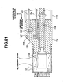
Fig. 21 is an enlarged sectional view of a distal end to be inserted of an insert port of an endoscope in the ultrasonic diagnostic apparatus according to the fourth example ; -
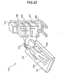
Fig. 22 is an external view in which the ultrasonic diagnostic apparatus according to the fourth example is used to a body to be examined; -
Fig. 23 is a conceptual diagram of data for describing position and direction data in the ultrasonic diagnostic apparatus according to the fourth example; -
Fig. 24 is an explanatory diagram showing an ultrasonic guide image in the ultrasonic diagnostic apparatus according to the fourth example; -
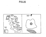
Fig. 25 is an explanatory diagram showing display examples displaying an ultrasonic image and an ultrasonic guide image together on a monitor in the ultrasonic diagnostic apparatus according to the fourth example; -
Fig. 26 is an explanatory diagram showing display examples displaying an ultrasonic image and an ultrasonic guide image together on a monitor in the ultrasonic diagnostic apparatus according to the fourth example; -
Fig. 27 is an explanatory diagram showing display examples displaying an ultrasonic image and an ultrasonic guide image together on a monitor in the ultrasonic diagnostic apparatus according to the fourth example; -
Fig. 28 is an explanatory diagram showing display examples displaying an ultrasonic image and an ultrasonic guide image together on a monitor in the ultrasonic diagnostic apparatus according to the fourth example; -
Fig. 29 is an explanatory diagram showing display examples displaying an ultrasonic image and an ultrasonic guide image together on a monitor in the ultrasonic diagnostic apparatus according to the fourth example; -
Fig. 30 is an explanatory diagram showing display examples displaying an ultrasonic image and an ultrasonic guide image together on a monitor in the ultrasonic diagnostic apparatus according to the fourth example; -
Fig. 31 is an explanatory diagram showing a variation example of a guide image in the ultrasonic diagnostic apparatus according to the fourth example; -
Fig. 32 is an explanatory diagram showing the variation example of a guide image in the ultrasonic diagnostic apparatus according to the fourth example; -
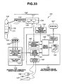
Fig. 33 is a schematic configuration diagram of an ultrasonic diagnostic apparatus according to a fifth example; -
Fig. 34 is an explanatory diagram showing a guide image example according to the fifth embodiment; -
Fig. 35 is a schematic configuration diagram of an ultrasonic probe according to a sixth example; -
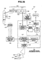
Fig. 36 is a schematic configuration diagram of an ultrasonic diagnostic apparatus according to a seventh example; and -
Fig. 37 is an explanatory diagram showing display examples displaying an ultrasonic image and an ultrasonic guide image on a monitor of the ultrasonic diagnostic apparatus according to the seventh example. - An embodiment of the invention and examples will be described below with reference to drawings.
-
Figs. 1 to 14 are diagrams describing a first embodiment of an ultrasonic diagnostic apparatus according to the invention.Fig. 1 is a block diagram showing an entire configuration of an ultrasonic diagnostic apparatus of the first embodiment.Fig. 2 is a block diagram showing a configuration of the distal end of an insert portion of an ultrasonic endoscope to be used in the ultrasonic diagnostic apparatus according to the first embodiment.Fig. 3 is a flowchart describing an operation for creating tomographic parallel images by performing a hand scanning by means of the ultrasonic diagnostic apparatus according to the first embodiment.Fig. 4 is an explanatory diagram of an ultrasonic tomographic image created by a hand scanning by means of the ultrasonic diagnostic apparatus according to the first embodiment.Fig. 5 is an explanatory diagram describing an operation for slicing an ultrasonic tomographic image by means of the ultrasonic diagnostic apparatus according to the first embodiment.Fig. 6 is an explanatory diagram describing Z buffer cells of the ultrasonic diagnostic apparatus according to the first embodiment.Fig. 7 is an explanatory diagram describing an arrangement of pixels on a monitor screen of the ultrasonic diagnostic apparatus according to the first embodiment.Fig. 8 is an explanatory diagram describing a display state on the monitor screen of the ultrasonic diagnostic apparatus according to the first embodiment.Fig. 9 is an explanatory diagram describing an operation for moving an ultrasonic tomographic image marker on the monitor screen of the ultrasonic diagnostic apparatus according to the first embodiment.Fig. 10 is a flowchart describing the operation for moving an ultrasonic tomographic image marker by the ultrasonic diagnostic apparatus according to the first embodiment.Fig. 11 is an explanatory diagram describing an operation for rotating tomographic parallel images on the monitor screen by the ultrasonic diagnostic apparatus according to the first embodiment.Fig. 12 is a flowchart describing an operation for rotating tomographic parallel images by the ultrasonic diagnostic apparatus according to the first embodiment.Fig. 13 is an explanatory diagram describing changing of a position of slicing tomographic parallel images and moving of a slice marker on the monitor screen of the ultrasonic diagnostic apparatus according to the first embodiment.Fig. 14 is a flowchart describing operations for changing a position of slicing tomographic parallel images and moving a slice marker by the ultrasonic diagnostic apparatus according to the first embodiment. - As shown in
Fig. 1 , an ultrasonic diagnostic apparatus according to the first embodiment includes anultrasonic endoscope 11a, an ultrasonic observingportion 12, aposition detecting portion 13, amonitor 14, akeyboard 15 and amouse 16. Theultrasonic endoscope 11a is an ultrasonic probe. The ultrasonic observingportion 12 includes tomographic parallel-images constructing means for creating tomographic parallel images from ultrasonic tomographic images, ultrasonic tomographic image marker setting means, slicing position setting means, rotating means, display control means, slicing means and rotating means and the like. Theposition detecting portion 13 is positional information detecting means. Themonitor 14 is display means. Thekeyboard 15 includes ultrasonic tomographic image marker setting means, slicing position setting means, rotating means and the like. - The
ultrasonic endoscope 11a, which is an ultrasonic probe, includes aninsert portion 21 and a drivingportion 23. Theinsert portion 21 contains a flexible material and is to be inserted into a body cavity of a body to be examined. The drivingportion 23 includes amotor 22 driving and rotating anultrasonic transducer 25, which will be described later, disposed at the distal end of theinsert portion 21. - An acoustically translucent distal-
end cap 24 is provided at the distal end of theinsert portion 21 of theultrasonic endoscope 11a as shown inFig. 2 . The distal-end cap 24 contains a material allowing ultrasonic wave to pass through. Theultrasonic transducer 25 is arranged in the distal-end cap 24 and an acoustic medium (not shown) is filled in theultrasonic transducer 25. - The
ultrasonic transducer 25 is mounted and fixed at a distal end of aflexible shaft 26 containing a flexible member. The other end of theflexible shaft 26 is connected to a rotationally-driving axis of themotor 22 of the drivingportion 23. - The
ultrasonic transducer 25 is connected to animage constructing circuit 31, which will be described later, of the ultrasonic observingportion 12 by a signal line (not shown) provided in theflexible shaft 26, through the drivingportion 23. - A
send coil 27 generating a magnetic field is provided at the distal end of the distal-end cap 24 of theinsert portion 21. Thesend coil 27 is connected to acoil driver circuit 41, which will be described, of theposition detecting portion 13 by a signal line (not shown) provided in theinsert portion 21. - The
send coil 27 is wound about theinsert portion 21 in two directions orthogonal to the axis direction (the shown X-axis direction and Y-axis direction with respect to the Z-axis of theinsert portion 21 shown inFig. 2 ). The Z-axis is a direction in which theinsert portion 21 of theultrasonic endoscope 11a is inserted. The X-axis and Y-axis are parallel to aradial scan plane 25c, which will be described later, and vertical to the Z-axis. - When the
motor 22 of the drivingportion 23 of theultrasonic endoscope 11a is driven and rotated, theflexible shaft 26 rotates in a direction indicated by the shown arrow. Then, theultrasonic transducer 25 is also driven and is rotated in the direction of aradial scan 25b indicated by the shown arrow. When theultrasonic transducer 25 is driven by ultrasonic oscillation, anultrasonic beam 25a is projected. - The ultrasonic observing
portion 12 has animage constructing circuit 31, a largecapacity image memory 32, animage processing circuit 33, adisplay circuit 34, a large capacity three-dimensionaldata recording portion 35, acommunication circuit 36 and an externalinput control circuit 37 and further includes acontroller 39. Theimage constructing circuit 31 outputs pulse-voltage-shaped exciting signals for driving by ultrasonic oscillation. Also, theimage constructing circuit 31 performs different kinds of signal processing on echo signals from theultrasonic transducer 25 and constructs ultrasonic image data. Theimage memory 32 stores image data created by theimage constructing circuit 31 and image data of plural ultrasonic tomographic images created by theimage processing circuit 33, which will be described later. Theimage processing circuit 33 is a circuit performing different kinds of image processing on image data stored in theimage memory 32 and includes tomographic parallel image constructing means. Thedisplay circuit 34 is a display control means. Thedisplay circuit 34 performs digital-analog converting processing on image data having undergone different kinds of image processing in theimage processing circuit 33 to convert analog video signals and causes themonitor 14 to display an image. The three-dimensionaldata recording portion 35 is a hard disk for storing image data constructed by theimage constructing circuit 31 and/or position and direction data, which will be described later, for a long period of time. Thecommunication circuit 36 performs different kinds of communication for exchanging different kinds of information with theposition detecting portion 13. The externalinput control circuit 37 receives an instruction input from thekeyboard 15 and/or themouse 16. Thecontroller 39 is a control portion giving a drive control command to theimage constructing circuit 31, theimage memory 32, theimage processing circuit 33, thedisplay circuit 34, the three-dimensionaldata recording portion 35, thecommunication circuit 36 and the externalinput control portion 37 through a bus 38 provided among thecircuits 31 to 37. Thecontroller 39 has tomographic parallel image constructing means, ultrasonic tomographic image marker setting means, slicing position setting means, rotating means, slicing means and rotating means and the like. - The
image memory 32 includes three areas. One of these areas stores image data of ultrasonic tomographic images output from theimage constructing circuit 31. Another area stores image data for displaying images created by theimage processing circuit 33 on themonitor 14. Another area stores a Z-buffer, which will be described later. - The
monitor 14 displays an ultrasonic tomographic image 51 (seeFig. 5 ) based on analog video signals generated by thedisplay circuit 34. Thekeyboard 15 has plural keys and is used to input instruction for different operations using these keys. Themouse 16 is used to input instructions for different operations by manipulating symbols and/or signs displayed on themonitor 14. - The
position detecting portion 13 includes acoil driver circuit 41, a receivecoil unit 44 and aposition calculating circuit 43. Thecoil driver circuit 41 outputs coil exciting signals to thesend coil 27 of theultrasonic endoscope 11a. The receivecoil unit 44 is placed and fixed at a specific position by a predetermined placing method, wherein the receivecoil unit 44 has plural receivecoils 42 sequentially detecting magnetic fields from thesend coil 27 and generates and outputs position signals. Theposition calculating circuit 43 calculates and generates position and direction data from position signals generated by the receivecoil unit 44. - The
recieve coil unit 44 has plural receivecoils 42 fixed integrally in a rectangular parallelepiped cabinet. InFig. 1 , the receive coils 42 are aligned and fixed on a straight line in the receivecoil unit 44 for the convenience of space of paper. However, in reality, the receive coils 42 may be aligned and fixed on a two-dimensional plane or in a three-dimensional space. - An operation for constructing the ultrasonic tomographic image 51 (see
Fig. 5 ) in the ultrasonic diagnostic apparatus having the above-described construction will be described. - The
ultrasonic transducer 25 generates and projects an ultrasonic beam, which is a compressional wave of a medium, based on pulse-voltage-shaped exciting signals from theimage constructing circuit 31 of the ultrasonic observingportion 12. The ultrasonic beam is projected to the outside of theinsert portion 21 of theultrasonic endoscope 11a via an acoustic medium filled in the distal end of theinsert portion 21 and the distal-end cap 24. The ultrasonic beam projected to the outside is reflected within a body to be examined and is input to theultrasonic transducer 25 as a reflected echo. Theultrasonic transducer 25 converts the reflected echo to echo signals and outputs the echo signal to theimage constructing circuit 31. - While operations of the projection of ultrasonic beams by the
ultrasonic transducer 25 and the generation of reflected echo signals are repeated, theflexible shaft 26 and theultrasonic transducer 25 rotate in the respective directions indicated by the shown respective arrows by rotationally driving themotor 22 within the drivingportion 23. Thus, the ultrasonic beams are sequentially and radially projected within theradial scan plane 25c vertical to the axis direction of theinsert portion 21 of theultrasonic endoscope 11a. As a result, so-called mechanical radial scanning (simply called radial scanning, hereinafter) 25b is performed. - The echo signals generated by the
ultrasonic transducer 25 undergo publicly known processing in theimage constructing circuit 31 of the ultrasonic observingportion 12 to construct so-called ultrasonic tomographic image data (simply called ultrasonic tomographic image, hereinafter). The publicly known processing may include envelope detection, logarithm multiplication, analog/digital conversion and scan conversion (processing converting image data of a polar coordinates system generated by radial scanning to image data of an orthogonal coordinates system). The ultrasonic tomographic image is stored in theimage memory 32 through the bus 38. - Next, an operation relating to position and direction data will be described.
- The
coil driver circuit 41 of theposition detecting portion 13 sequentially outputs an exciting signal to thesend coil 27. Based on the exciting signal, thesend coil 27 spatially generates a magnetic field. On the other hand, the receivecoil 42 of the receivecoil unit 44 sequentially detects magnetic fields from thesend coil 27 and generates a position signal. Then, the receivecoil 42 outputs the position signal to theposition calculating circuit 43. - The
position calculating circuit 43 calculates position and direction data based on the position signal from the receivecoil 42 and outputs the position and direction data to thecommunication circuit 36. The position and direction data is data including a position and direction of thesend coil 27 with respect to the receivecoil unit 44. More specifically, position and direction data includes not only a position of thesend coil 27 but also a direction (Z-axis direction inFig. 2 ) that theultrasonic endoscope 11a is inserted and a specific direction (Y-axis direction inFig. 2 ) parallel to an ultrasonic tomographic image. - Here, when the
send coil 27 is mounted at the distal-end cap 24 of theinsert portion 21 such that the Y-axis inFig. 2 can be at 12 o'clock position of the ultrasonic tomographic image (the upper direction of the ultrasonic tomographic image displayed on themonitor 14, the position and direction data includes the direction of the normal (Z-axis inFig. 2 ) and the direction of 12 o'clock (Y-axis inFig. 2 ) of the ultrasonic tomographic image. - The
communication circuit 36 receives position and direction data from theposition calculating circuit 43 via the bus 38 and outputs the data to theimage memory 32. Theimage memory 32 stores the data. - The ultrasonic tomographic image and the position and direction data are stored in the
image memory 32 in connection and in synchronization with each other under the control of thecontroller 39. - Next, an operation of the
controller 39 for generating tomographic parallel images for performing an ultrasonic diagnosis by using theultrasonic endoscope 11a will be described with reference toFig. 3 . - When an operator operating the ultrasonic diagnostic apparatus causes the display of a menu having different items and inputs a selection of an item from the displayed menu by using the
keyboard 15 and/or themouse 16, the data of the selected item is transmitted from the externalinput control circuit 37 to thecontroller 39. In accordance with the selection input, thecontroller 39 drives and controls thecircuits 31 to 36. In the processing inFig. 3 , under the control of thecontroller 39, the construction of an ultrasonic tomographic image, the slicing of the tomographic image and/or the construction of tomographic parallel images thereof may be performed. - In other words, when an operator inputs a manipulation for starting an ultrasonic diagnosis (command for starting a hand scanning) at a step S101, the
controller 39 drives and controls theimage constructing circuit 31 to output an exciting signal to theultrasonic transducer 25. Furthermore, thecontroller 39 drives and rotates themotor 22 and starts theradial scanning 25b of theultrasonic transducer 25. - At a step S102, the operator repeats the hand scanning for inserting and withdrawing the
insert portion 21 of theultrasonic endoscope 11a within a body cavity of a body to be examined along a lumen by performing theradial scanning 25b at the same time. Based on a reflected echo from theultrasonic transducer 25, thecontroller 39 drives and controls theimage constructing circuit 31, and ultrasonic tomographic images are constructed sequentially. This scanning method is called "hand scanning", hereinafter. The ultrasonictomographic image 51 and the tomographicparallel images 53 are constructed through ascanning path 54, which is a path of the hand scanning (seeFigs. 5 and8 ). In accordance with the advance of the hand scanning, thescanning path 54 sequentially extends (Fig. 5 ). - Once the hand scanning starts, the
controller 39 causes theimage constructing circuit 31 to sequentially construct ultrasonic tomographic images as shown inFig. 4 based on reflected echoes from theultrasonic transducer 25 at a step S103. InFig. 4 ,reference numerals 1 to n are given to the ultrasonic tomographic images in order of the construction. - The ultrasonic tomographic image constructed by the
image constructing circuit 31 is stored in theimage memory 32 in synchronization and in connection with the position and direction data calculated by theposition calculating circuit 43 when the ultrasonic tomographic image is constructed. An example of the ultrasonictomographic image 51 which is displayed on themonitor 14 is shown as the ultrasonictomographic image 51 in (a) ofFig. 5 . - Next, at a step S104, the
controller 39 drives and controls theimage processing circuit 33 to read the ultrasonic tomographic image and the position and direction data from theimage memory 32, slice the ultrasonictomographic image 51 and create slices 52. - A position slicing the ultrasonic
tomographic image 51 is preset. For example, when it is preset that the ultrasonictomographic image 51 shown in (a) ofFig. 5 is sliced at a straight line through the center of the image (that is, the rotational center of the ultrasonic transducer 25), the slicing at the slicing position results inslices 52 including aslice 52 shown in (b) ofFig. 5 . The setting of the slicing position may be changed. - The
slices 52 resulting from the slicing at the slicing position at the step S104 undergo coordinates conversion based on the position and direction data and a line-of-sight direction in theimage processing circuit 33 under the control of thecontroller 39 at the step S105. - The line-of-sight direction is a direction vertical to a monitor screen showing a plane of the tomographic
parallel images 53 displayed on themonitor 14. The line-of-sight direction is preset. - A relationship between the
slice 52 after the coordinates conversion and a monitor screen is shown as a sliced state shown in (c) ofFig. 5 . The sliced state shown in (c) ofFig. 5 shows on themonitor 14 only one of theslices 52 having undergone coordinates conversion. However,Fig. 5 does not illustrate an example of a real screen displayed on themonitor 14 but is an explanatory diagram illustrating the relationship between theslice 52 and the monitor screen. - Next, at a step S106, the
controller 39 drives and controls theimage processing circuit 34 to calculate a depth of pixels on the slice from the monitor screen. - The depth from the monitor screen is a distance between an assumed plane and each pixel on the slice. In this case, a plane corresponding to a position of the monitor screen is assumed in a space. Coordinates of the receive
coil unit 44 of each pixel on the slice are calculated from the position and direction data.Fig. 5 shows in (d) a relationship between the assumed plane corresponding to a given monitor screen and pixels on the slice. - Pixels on the slice may be on a plane than the plane expressing the monitor screen in the line-of-sight direction according to settings of the assumed plane. However, in subsequent steps, the closer pixels are processed as "pixels having negative depth". Here, for convenience of explanation, by assuming that the plane is sufficiently far away from a first slice, pixels on all slices are assumed to be deeper than the plane. Thus, depth is adopted for all of them in following descriptions.
- When the calculation of the depth from the monitor screen at the step S106 has completed, the
controller 39 drives and controls theimage processing circuit 33 to compare depths of the pixels on the slices and stored values of Z-buffer cells, which will be described later, at a step S107. - The Z-buffer cell is a cell corresponding to each pixel on the monitor screen, as shown in the conceptual diagram of a Z-buffer in
Fig. 6 . The Z-buffer cell stores a depth from a monitor screen to a pixel on a slice. - Each of the Z-buffer cells stores a storable maximum value as an initial value. In other words, an initial value of each Z-buffer cell is set deepest.
- The
image processing circuit 33 compares a depth of each pixel on the slice from the monitor screen and a value stored in a respective Z-buffer cell and calculates a large-small relationship with respect to the value. - Next, at a step S108, in accordance with the comparison between the pixel depth and the Z-buffer cell storing value at the step S107, the
controller 39 performs a following process. - (I) If "the depth of a pixel < a value stored in the Z-buffer cell",
- (a) The
image processing circuit 33 updates the value stored in the Z-buffer cell to the depth of the pixel on the slice.
In other words, the hand scanning is continued, and the serialplural slices 52 are obtained through steps, which will be described below. Then, each Z-buffer cell stores a depth of a shallowest pixel immediately under pixels on the monitor screen among pixels on the plural slices from the monitor screen. - (b) The
image processing circuit 33 alternatively updates the value stored in a display cell, which will be described later, to a luminance value of a pixel on theslices 52.
As shown inFig. 7 , which is a conceptual diagram of an area storing monitor screens of theimage memory 32, the area of theimage memory 32 includes cells (called display cell, hereinafter) corresponding to pixels, respectively, on a monitor screen. The display cell stores a luminance value to be displayed by themonitor 14.
In this way, when a given pixel on theslice 52 compared at the step S107 is shallowest, theimage processing circuit 33 updates the value stored in the display cell to the luminance value. Therefore, when the hand scanning is continued and the serialplural slices 52 are obtained through steps, which will be described, each display cell stores a luminance value of a shallowest pixel immediately under the pixels on the monitor screen among pixels on the plural slices. - (a) The
- (II) If "the depth of a pixel ≥ a value stored in the Z-buffer cell",
theimage processing circuit 33 does not perform any processing. - In other words, when the hand scanning is continued, and the serial
plural slices 52 are obtained through steps, which will be described later, theimage processing circuit 33 sequentially overlays theslices 52 to the closer side in the line-of-sight direction. This state is shown as the relationship state between a plane corresponding to the monitor screen and each pixel on the slices in (d) ofFig. 5 . In the relation state in (d) ofFig. 5 , pixels on the left side with respect to the line of intersection of the newest slice and an old slice among pixels on the newest slice are mainly shallower than the old slice. On the other hand, the pixels on the right side are mainly deeper than the old slice. - Therefore, the pixels on the left side on the newest slice appear to an operator to be overwritten on the tomographic parallel images. The tomographic
parallel images 53 created in this way are shown as tomographic parallel images shown in (e) ofFig. 5 . - Next, at a step S109, the
controller 39 controls themonitor 14 to display side by side the newest ultrasonic tomographic image and the newest tomographic parallel images. - A display example including the ultrasonic tomographic image and the tomographic parallel images on the monitor screen is shown in
Fig. 8 . InFig. 8 , the ultrasonictomographic image 51 is displayed on the right while the tomographicparallel images 53 are displayed on the left. A receivecoil unit marker 56 is displayed near the tomographicparallel images 53. The receivecoil unit marker 56 indicates a direction of the rectangular parallelepiped receivecoil unit 44. When themonitor 14 displays up to the step S109 the old ultrasonictomographic image 51 and the tomographicparallel images 53 in which theold slices 52 are piled, the monitor screen is updated. - At a step S110, the
controller 39 terminates radial scanning when an operator inputs an instruction for terminating the hand scanning through thekeyboard 15 and/or themouse 16. Otherwise, the processing returns to the steps S103. - More specifically, when the operator selects one of different items in a menu and instructs to terminate the hand scanning by using the
keyboard 15 and/or themouse 16, theimage constructing circuit 31 terminates outputting an exciting signal based on the instruction from thecontroller 39. Thus, the driving of the rotation of themotor 22 is terminated, and the radial scanning is terminated. In this way, as far as an operator instructs the termination of the hand scanning, the processing from the step S103 to the step S110 are repeated. - By repeating the processing at the steps S103 to S110, the tomographic
parallel images 53 are sequentially extended as shown in the tomographic parallel images in (e) ofFig. 5 or as shown in tomographic parallel images inFig. 8 in accordance with the hand scanning. Here, the ultrasonictomographic image 51 inFig. 8 is updated to the newest ultrasonic tomographic image in accordance with the hand scanning and is displayed. - When the tomographic
parallel images 53 are about to lie off the monitor screen in accordance with the hand scanning, theimage processing circuit 33 promptly scrolls the tomographicparallel images 53 before the display at the step S109 such that thenewest slice 52 can be displayed entirely within the monitor screen. - Hand scanning for generating tomographic parallel images has been described above. Next, an operation after the hand scanning will be described.
- An operator can select again an ultrasonic tomographic image to be displayed on the right side of a monitor screen from plural serial ultrasonic
tomographic images 51 obtained through hand scanning. As shown inFig. 9 , the oneslice 52 resulting from the slicing of the ultrasonictomographic image 51 to be displayed on the right of the monitor screen is displayed in a different color, such as green, on the tomographicparallel images 53 for distinction. The slice displayed in a different color is called an ultrasonictomographic image marker 55, hereinafter. - An operator can instructs selectively and sequentially to move the ultrasonic
tomographic image marker 55 from the externalinput control circuit 37 to theadjacent slice 52 by using thekeyboard 15 and/or themouse 16. The display color of theslice 52 of the tomographicparallel images 53, which is indicated by the instruction for moving the ultrasonictomographic image marker 55, is changed to green. Then, theslice 52 originally having the ultrasonictomographic image marker 55 instructed to move is returned to a slice of an ultrasonic tomographic image in a same color as the other uninstructed plural slices, that is, in black and white. Then, the ultrasonictomographic image 51 on which the indicatedslice 52 is based is displayed on the right side of the monitor screen. - In other words, in connection with the selective movement of the ultrasonic
tomographic image marker 55 in the tomographic parallel images on the monitor screen to the position of a desiredslice 52, the ultrasonictomographic image 51 is updated and is displayed. - Referring to the flowchart in
Fig. 10 , the operation will be further described in detail. The processing inFig. 10 is performed under the control of thecontroller 39 in accordance with an instruction for moving an ultrasonic tomographic marker from thekeyboard 15 and/or themouse 16. - First of all, an operator selects an item for moving an ultrasonic tomographic image marker from different items in a menu by using the
keyboard 15 and/or themouse 16. At a step S201, thecontroller 39 receives through the externalinput control circuit 37 an instruction for moving the ultrasonictomographic image marker 55 to the position of theadjacent slice 52. At a step S202, thecontroller 39 controls and drives theimage processing circuit 33 andsubstitutes 1 for a variable n of a counter provided in theimage processing circuit 33. - Next, at a step S203, the
controller 39 causes theimage processing circuit 33 to read the nth ultrasonic tomographic image and the position and direction data among the plural serial ultrasonictomographic images 51 stored in theimage memory 32. At a step S204, theimage processing circuit 33 slices the read nth ultrasonictomographic image 51 and createsslices 52. The creation of the slices at the step S204 is the same process as the process at the step S104 inFig. 3 , and the detail description will be omitted here. - When the
slices 52 of the ultrasonictomographic image 51 are created at the step S204, thecontroller 39 controls at the S205 the driving of theimage processing circuit 33 and judges whether or not the read nth ultrasonic tomographic image is the ultrasonic tomographic image which is the base of the slice to which the ultrasonictomographic image marker 55 is moved by being instructed at the step S201. If the nth ultrasonic tomographic image is determined as the ultrasonic tomographic image, the processing jumps to a step S206. If not, the processing jumps to a step S208. - At the step S205, if it is determined that the read nth ultrasonic tomographic image is the newly indicated ultrasonic tomographic image that the ultrasonic
tomographic image marker 55 is moved to, thecontroller 39 at a step S206 drives and controls theimage processing circuit 33 to update the ultrasonic tomographic image displayed on the right side of the monitor screen to the nth ultrasonic tomographic image. At a step S207, a slice of the nth ultrasonic tomographic image is colored green. In other words, the slice of the nth ultrasonic tomographic image is the new ultrasonictomographic image marker 55 now. - Next, at the step S208, the
controller 39 control theimage processing circuit 33 to perform coordinates conversion of the slices based on the position and direction data and the line-of-sight direction like the step S105. At a step S209, theimage processing circuit 33 calculates the depths of the pixels from the monitor screen to the slice like the step S106. At a step S210, theimage processing circuit 33 compares the depths of the pixels on the slice and the values stored in respective Z-buffer cells like the step S107. Furthermore, at a step S211, like the step S108, theimage processing circuit 33 performs a process in accordance with the comparison between the depths of the pixels and the values stored in the Z-buffer cells. - Next, at a step S212, the
controller 39 updates and displays the ultrasonictomographic image 51 and the newly created tomographicparallel images 53 to be displayed on themonitor 14 side by side as shown inFig. 9 . - When the display update for the
monitor 14 has completed at the step S212, thecontroller 39 at a step S213 judges whether a process for reading all of the plural serial ultrasonic tomographic images obtained by hand scanning has completed or not. If the reading process has not completed, a step S214 and subsequent steps are performed. More specifically, if n is the last image of the plural serial ultrasonic tomographic images obtained by hand scanning, thecontroller 39 causes theimage processing circuit 33 to complete all of the above-described processing. If n is not the last image of the plural serial ultrasonic tomographic images, theimage processing circuit 33 is caused to add 1 to the variable n provided as a counter at a step S214. Then, the processing jumps to the step S203, and the processing from the step S203 to the step S214 is repeated. - As described above, by performing the processing from the step S201 to the step S214, the ultrasonic
tomographic image marker 55 is moved to the position of theadjacent slice 52. In connection therewith, the ultrasonictomographic image 51 is updated and is displayed. - An operator repeats the instruction performed at the step S201 by using the
keyboard 15 and/or themouse 16 so that the ultrasonictomographic image marker 55 on the tomographicparallel images 53 can be selectively moved to the position of a desiredslice 52. In connection therewith, the desired ultrasonictomographic image 51 can be displayed. - At the initial state, that is, immediately after hand scanning, the
monitor 14 displays the tomographicparallel images 53 along thescanning path 54 by the hand scanning and the newest obtained ultrasonictomographic image 51 as shown inFig. 8 . Here,Fig. 8 does not show the ultrasonictomographic image marker 55. This is because the ultrasonictomographic image marker 55 appears when an operator first instructs to move the ultrasonictomographic image marker 55 to a position of theadjacent slice 52 at the step S201. - Next, as shown in
Fig. 11 , when an instruction is given for driving the rotation of a receivecoil unit marker 56 of the monitor screen, the tomographicparallel images 53 can be rotated in connection with the rotation of the receivecoil unit marker 56. The rotational operation of tomographic parallel images will be described with reference toFig. 12 . The processing inFig. 12 is performed under the control of thecontroller 39 in accordance with an instruction for a line-of-sight (rotation) from thekeyboard 15 and/or themouse 16. - At a step S301, an operator inputs an instruction for rotating the receive
coil unit marker 56 by using thekeyboard 15 and/or themouse 16. Then, the instruction is input to thecontroller 39 through the externalinput control circuit 37. Then, through thedisplay circuit 34, the receivecoil unit marker 56 displayed on themonitor 14 is rotated in the direction indicated by the arrow inFig. 11 , and the tomographicparallel images 53 are also rotated in connection thereto. This state is checked on themonitor 14 by the operator. The rotation of the tomographicparallel images 53 is set such that the rotation in a new line-of-sight direction can be a direction from the closer side to the deep side inFig. 11 by regarding the receivecoil unit marker 56 as the receivecoil unit 44. - At the step S301, after the line-of-sight direction of the tomographic
parallel images 53 is set by using the receivecoil unit marker 56, the processing from a step S302 to a step S314 is performed. Since the processing from the step S302 to the step S314 are the same as the steps S202 to S214, the description thereof will be omitted here. - In other words, the
image processing circuit 33 reads from theimage memory 32 the plural serial ultrasonictomographic images 51 resulting from hand scanning. Then, theimage processing circuit 33 can construct new tomographicparallel images 53 in the set new line-of-sight direction. - In this description, the tomographic
parallel images 53 are rotated after the operator rotates the receive coil unit marker. However, the rotated tomographicparallel images 53 can be re-constructed every time the receivecoil unit marker 56 slightly rotates if the processing by thecontroller 39, bus 38,image processing circuit 33,display circuit 34 and so on is fast enough. In this case, it appears to an operator that the receivecoil unit marker 56 and the tomographicparallel images 53 rotate in connection with each other simultaneously. - Next, an operation for changing a position of slicing the ultrasonic
tomographic image 51 will be described. As shown inFig. 13 , aslicing line marker 57 is displayed on the ultrasonictomographic image 51 displayed on the monitor screen. Then, a new slicing position is defined by moving theslicing line marker 57 in accordance with an input of an instruction via thekeyboard 15 and/or themouse 16. Thus, the tomographicparallel images 53 of theslice 52 resulting from the slicing at the new slicing position are created. - The operation for changing the slicing position will be described with reference to the flowchart in
Fig. 14 . The processing inFig. 14 is performed under the control of thecontroller 39 in accordance with an instruction for a slicing position from thekeyboard 15 and/or themouse 16. - At a step S401, an operator selects an item for changing a slicing position on the menu from the external
input control circuit 39 to thecontroller 39 by using thekeyboard 15 and/or themouse 16. Then, thecontroller 39 controls theimage processing circuit 33 and thedisplay circuit 34 to display theslicing line marker 57 on a segment of the ultrasonictomographic image 51 on the right side of a monitor screen shown inFig. 13 . When the operator instructs to move theslicing line marker 57 via thekeyboard 15 and/or themouse 16, the slicingmarker 57 moves in the direction indicated by the arrow inFig. 13 , for example, in accordance with the instruction. The state is checked by an operator on the monitor, and the slicing position is defined at the position of the newly moved slicingline marker 57. - When the setting for moving a slicing line marker position at the step S401 has completed, the processing from a step S402 to a step S414 are performed. Since the processing from the step S402 to the step S414 is the same as the processing at the step S202 to S214, the detail description will be omitted here. In other words, the
image processing circuit 33 reads from the image memory the plural serial ultrasonic tomographic images resulting from hand scanning. Then, theimage processing circuit 33 can construct the tomographicparallel images 53 of a slice resulting from the slicing at a defined new slicing position. The tomographicparallel images 53 are updated and displayed at the new slicing position in connection with the movement of theslicing position marker 57. - In this description, the tomographic
parallel images 53 are re-constructed after the operator moves theslicing line marker 57. However, the rotated tomographicparallel images 53 can be re-constructed every time the slicing line marker slightly moves if the processing by thecontroller 39, bus 38,image processing circuit 33,display circuit 34 and so on is fast enough. In this case, it appears to an operator that theslicing line marker 57 and the tomographicparallel images 53 vary in connection with each other simultaneously. - The
slicing line marker 57 is displayed in a different color such as green from the color of the background so as to be distinctive when an image of the background is black and white. - As described above, since the tomographic
parallel images 53 are displayed during hand scanning, the density of an image can be easily recognized with respect to which part of a body cavity of a subject and how many images are picked up. Therefore, unexpected failures in picking up images may hardly occur. - Since the newest ultrasonic
tomographic image 51 and the tomographicparallel images 53 are displayed on the right and left sides, respectively, on the monitor screen during the hand scanning, which part is scanned for an ultrasonic tomographic image displayed on the current screen can be easily recognized. For example, when theinsert portion 21 of theultrasonic endoscope 11a is inserted and/or withdrawn along the digestive tract from the esophagus to the duodenum through the stomach, the locus substantially and anatomically agrees with the form of the digestive tract. By using the fact, an operator can clearly identify which part within a body cavity the distal end of the insert portion of the ultrasonic endoscope exists based on the tomographic parallel images. - After the hand scanning, a slice expressing the ultrasonic tomographic image displayed on the monitor screen has a different color as an ultrasonic tomographic image marker from that of the other slices. Thus a correspondence between the ultrasonic tomographic image and the tomographic parallel images can be expressed. Therefore, which part of a curved or bent lumen is scanned to obtain the ultrasonic tomographic image can be easily recognized. As a result, a desired ultrasonic tomographic image can be easily obtained, and an area of concern such as a lesion can be easily rendered and discovered.
- Furthermore, an ultrasonic tomographic image marker on topographic parallel images is moved by using input means such as a keyboard and a mouse, and an ultrasonic tomographic image is updated in connection therewith. Thus, the tomographic parallel images can be used as a guide for searching an ultrasonic tomographic image. In addition, since an ultrasonic tomographic image is updated by moving an ultrasonic tomographic image marker little by little. Thus, connections among internal organs and the travel of vessels can be easily understood. Also, a spatial positional relationship between a lesion and surrounding organs can be more easily understood.
- The image processing circuit creates tomographic parallel images by slicing an ultrasonic tomographic image and overwriting the shallowest pixel on a slice thereof. Thus, when a slicing position crosses a lesion, an organ and/or a vessel, a connection of lesions, connection of organs and travel of vessels along hand scanning can be recognized at a glance. By rotating tomographic parallel images, the tomographic parallel images can be observed in a direction that the connection of lesions, connection of organs and travel of vessels along hand scanning can be further easily understood. Furthermore, a slicing position is adjusted and operated to be changed on an ultrasonic tomographic image by using an input unit such as a keyboard and a mouse. Thus, tomographic parallel images including a lesion, an organ and/or a vessel at the slicing position can be easily created.
- A receive coil unit marker indicating a direction of a receive coil unit is provided near tomographic parallel images. Thus, a direction of the observation of the tomographic parallel images can be further easily understood, and the direction of hand scanning can be further easily understood.
- Tomographic parallel images are created by slicing an ultrasonic tomographic image and overwriting the shallowest pixel every time the ultrasonic tomographic image is constructed during hand scanning. Thus, processing such as interpolating processing required for constructing a three-dimensional image is not necessary, and tomographic parallel images can be created and be updated fast. In addition, while an operator performs hand scanning, and the operator can observe live tomographic parallel images along hand scanning.
- Therefore, an ultrasonic diagnostic apparatus according to the first embodiment may be used to easily and realistically observe an extension of an invasion along a lumen of a lesion, a depth of a vertical invasion from a surface of a lumen and a spread and depth of an invasion to an organ and/or a portal vein in a deeper part from a lumen by moving a radial scan type ultrasonic endoscope within a body cavity.
- In the description of the first embodiment of the ultrasonic diagnostic apparatus according to the invention, tomographic parallel images are re-constructed by moving a slicing line marker on the tomographic parallel images. However, the slicing line marker may be fixed, and tomographic parallel images may be moved in parallel or be rotated within a monitor screen.
- The hand scanning may be performed in any one direction between a direction that the insert portion of the ultrasonic endoscope is withdrawn from a deep part of a body cavity or a direction that the insert portion is inserted to the deep part within the body cavity.
- In the description above, an ultrasonic tomographic image and tomographic parallel images are displayed on the monitor screen simultaneously. However, an ultrasonic tomographic image and tomographic parallel images may be displayed separately on separate monitors, respectively. Alternatively, an ultrasonic tomographic image and tomographic parallel images may be alternately switched and displayed on a single monitor screen.
- In the description above, displaying an ultrasonic tomographic image and tomographic parallel images thereof after the hand scanning uses the ultrasonic tomographic image and position and direction data stored in an image memory. However, the ultrasonic tomographic image and the position and direction data may be recorded in a three-dimensional data recording portion instead of an image memory immediately after the hand scanning, and the ultrasonic tomographic image and tomographic parallel images recorded in the three-dimensional data recording portion may be used after the hand scanning.
- In the description above, the ultrasonic tomographic image marker is a slice corresponding to ultrasonic tomographic image displayed on the right side of a monitor screen and having a different display color from that of the other slices. However, a specific slice may be distinguished in any display form. For example, an ultrasonic tomographic image marker may have a different luminance instead of a different color. Alternatively, an ultrasonic tomographic image marker may have a specific mark such as a circle or a square on a slice corresponding to an ultrasonic tomographic image displayed on the right side of a monitor screen. Alternatively, an ultrasonic tomographic image marker may be a slice having a frame in a specific color corresponding to an ultrasonic tomographic image displayed on the right side of a monitor screen.
- In the description above, a send coil is provided at the distal end of the insert portion of the ultrasonic endoscope while the receive coil is fixed in a space. However, the send coil and the receive coil may be provided oppositely.
- Furthermore, in the description above, the position and direction of an ultrasonic tomographic image are detected by using a magnetic field thereof. However, apparently, another means for detecting a position and a direction may be provided.
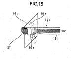
- Next, a second example of an ultrasonic diagnostic apparatus will be described with reference to
Figs. 15 and16 .Fig. 15 is a block diagram showing a configuration of a distal end of an insert portion of an ultrasonic endoscope to be used in an ultrasonic diagnostic apparatus according to the second example. -
Fig. 16 is a block diagram showing an entire configuration of the ultrasonic diagnostic apparatus according to the second example. The same reference numerals are given to the same components inFigs. 1 and2 , and the detail descriptions thereof will be omitted here. - An
ultrasonic transducer array 81 is provided at a distal end of aninsert portion 21 of anultrasonic endoscope 11b to be used in an ultrasonic diagnostic apparatus according to the second embodiment. Theultrasonic transducer array 81 is produced by slicing an ultrasonic transducer into rectangular pieces, and the pieces are arranged as a ring-shaped array around theinsert portion 21 in the axis direction. The ultrasonic transducers included in theultrasonic transducer array 81 are connected to animage constructing circuit 31 of an ultrasonic observingportion 12 through asignal line 82 and a drivingportion 23. - The
ultrasonic transducer array 81 is of a so-called electronic radial scan type in which a ring-shaped array is sequentially switched and driven from theimage constructing circuit 31 via the drivingportion 23, and an ultrasonic beam 81a is oscillated thereby such that aradial scanning 82a can be performed electronically. - A part of or plural ultrasonic transducers among the ultrasonic transducers included in the
ultrasonic transducer array 81 generate and output ultrasonic wave, which is a compressional wave of a medium, in response to an exciting signal in a pulse-voltage shape from theimage constructing circuit 31 of the ultrasonic observingportion 12. In this case, theimage constructing circuit 31 delays exciting signals such that the exciting signals can reach the ultrasonic transducers at different times. The delay is defined such that one ultrasonic beam 81a can be formed when ultrasonic waves excited by the ultrasonic transducers are overlapped within a body to be examined. The ultrasonic beam 81a is irradiated to the outside of theultrasonic endoscope 11b, and reflected echo from the inside of a body to be examined is input to each of the ultrasonic transducers. Each of the ultrasonic transducers converts the reflected echo to an electric echo signal and outputs the echo signal to theimage constructing circuit 31. - In order to perform the
radial scanning 82a indicated by the arrow inFig. 15 by using the ultrasonic beam 81a output from theultrasonic transducer array 81, theimage constructing circuit 31 re-selects plural ultrasonic transducers relating to the formation of the ultrasonic beam 81a and sends exciting signals again. Thus, the angle of the ultrasonic beam 81a is changed, and so-called radial scanning is performed. - In other words, the
ultrasonic endoscope 11a according to the first embodiment of the present invention performs mechanical radial scanning in which theultrasonic transducer 25 is rotated by themotor 22. On the other hand, theultrasonic endoscope 11b according to the second example selects and drives an ultrasonic transducer outputting the ultrasonic beam 81a from plural ultrasonic transducers in theultrasonic transducer array 81 and performs electronic radial scanning, which is different from the first embodiment. The other configurations and operations are entirely the same. - Since mechanical radial scanning is adopted according to the first embodiment, a twist occurs in the
flexible shaft 26. The twist causes ununiformity among plural ultrasonic tomographic images, and a distortion may occur on tomographic parallel images. This is because, in mechanical radial scanning, a position of a rotational angle of a motor is detected by a rotary encoder adjacent to the motor. - However, since a mechanical twist and/or an error may not occur when electronical radial scanning is adopted, no distortion occurs on tomographic parallel images.
- Apparently, the electronic radial scanning according to the second example may be 270° radial scanning, for example, as well as 360° radial scanning.
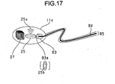
- Next, a variation example of the
ultrasonic endoscope 11b used in an ultrasonic diagnostic apparatus according to the second embodiment will be described with reference toFig. 17. Fig. 17 is a block diagram showing an ultrasonic endoscope according to this variation example. - The ultrasonic endoscope in the variation example shown in
Fig. 17 is a capsule ultrasonic endoscope 11c in which an ultrasonic endoscope is stored in a capsule as a radial scan type ultrasonic probe. - The capsule ultrasonic endoscope 11c contains in the capsule the
send coil 27, theultrasonic transducer 25, amicromotor 83, and a rigid shaft 83a extending from a rotational axis of themicromotor 83 and holding and fixing theultrasonic transducer 25. - A
signal cable 85 extends from the capsule ultrasonic endoscope 11c. Asignal line 84 of thesignal cable 85 is connected to theultrasonic transducer 25 as a signal of themicromotor 83 and is connected to the drivingportion 23. - The
micromotor 83 of the capsule ultrasonic endoscope 11c drives the rotation of theultrasonic transducer 25 through the rigid shaft 83a. The rotational direction of the rigid shaft 83a is a direction of theradial scanning 25b of theultrasonic transducer 25. - A rotational twist between the micromotor 83 and the
ultrasonic transducer 25 may not occur easily when themicromotor 83 and theultrasonic transducer 25 are brought closer by using the rigid shaft 83a. Thus, images with no distortion among ultrasonic tomographic images can be created by preventing a different between the rotation of themicromotor 83 and the rotation of theultrasonic transducer 25. - The capsule ultrasonic endoscope 11c can be reduced in size since components such as an optical observation window, a CCD camera, a light guide fiber and a video-signal cable are not required. Thus, a load on a subject can be reduced when the subject swallows the capsule ultrasonic endoscope into his/her body cavity, and scanning in the body cavity can be easier. Therefore, an operator can easily recognize an observed position within the body cavity and can perform observation easily.
- Furthermore, since the capsule ultrasonic endoscope 11c can be inserted or be withdrawn by natural swallowing, falling and writhing, hand scanning within a body cavity can be easier.
- Next, an ultrasonic endoscope according to a third example to be applied to the ultrasonic diagnostic apparatus will be described with reference to
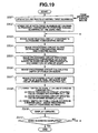
Figs. 18A and 18B andFig. 19 .Fig. 18A is an explanatory diagram showing a configuration and operation of the ultrasonic endoscope according to the third example.Fig. 18B is a diagram showing ultrasonic tomographic images resulting from twist scanning by the ultrasonic endoscope.Fig. 19 is a flowchart describing an operation of an ultrasonic diagnostic apparatus to which the ultrasonic endoscope according to the third example is applied. A configuration of the ultrasonic diagnostic apparatus to which the ultrasonic endoscope according to the third example is applied is common to that of the ultrasonic diagnostic apparatus according to the second example inFig. 16 . - An
ultrasonic endoscope 11d according to the third example includes anultrasonic transducer array 86 at the distal end of aninsert portion 21. As shown inFig. 18A , theultrasonic transducer array 86 is produced by slicing an ultrasonic transducer into rectangular pieces, and the pieces are arranged in a substantial arc form in a direction that the ultrasonic transducers are inserted. - The ultrasonic transducers included in the
ultrasonic transducer array 86 are connected to animage constructing circuit 31 of an ultrasonic observingportion 12 via asignal line 82 and a drivingportion 23. - In order to perform different kinds of treatments by observing ultrasonic tomographic images at the same time, the
ultrasonic endoscope 11d includes achannel 87, which is a through-hole into which a puncture needle and/or a forceps (not shown) is inserted through the insert portion. - In the
ultrasonic endoscope 11d, ultrasonic wave, which is a compressional wave of a medium, is projected to a part of and plural ultrasonic transducers included in theultrasonic transducer array 86 in response to an exciting pulse-voltage-shape signals from theimage constructing circuit 31 of the ultrasonic observingportion 12. - When the ultrasonic wave is projected, the
image constructing circuit 31 delays exciting signals such that the exciting signals to be supplied to the ultrasonic transducers can reach the ultrasonic transducers at different times. The delay is defined such that oneultrasonic beam 86a can be formed when ultrasonic waves excited by the ultrasonic transducers overlap within a body to be examined. - The
ultrasonic beam 86a is irradiated to the outside of theultrasonic endoscope 11d, and reflected echo from the inside of a body to be examined is input to each of the ultrasonic transducers. Each of the ultrasonic transducers converts the reflected echo to an electric echo signal and outputs the echo signal to theimage constructing circuit 31. - In order to perform
convex scanning 86b indicated by the shown arrow by using theultrasonic beam 86a projected from theultrasonic transducer array 86 of theultrasonic endoscope 11d, theimage constructing circuit 31 sequentially selects and sends the exciting signal to plural ultrasonic transducers. - Thus, the angle of the
ultrasonic beam 86a projected from theultrasonic transducer array 86 is changed, and so-called convex scanning is performed. - An ultrasonic tomographic image and tomographic parallel images can be created by using the
ultrasonic endoscope 11d like the first to third embodiment and examples, respectively. - An operation during twist scanning for creating tomographic parallel images during an ultrasonic diagnosis using the
ultrasonic endoscope 11d will be described with reference toFig. 19 . - At a step S501, an operator inputs an instruction for displaying a menu having different items and selects an item for starting twist scanning from the menu via a
keyboard 15 and/or amouse 16. An exciting signal for driving theultrasonic transducer array 86 is output from thecontroller 39 to theimage constructing circuit 31, and convex scanning is started. - Next, at a step S502, the operator starts rotating (twists, hereinafter) the
ultrasonic endoscope 11d within a body cavity of a body to be examined about the insert axis while convex scanning. By repeating the convex scanning with the twists at subsequent steps, ultrasonic tomographic images can be constructed sequentially. This scanning method is called "twist scanning", hereinafter. The state of the twist scanning is shown inFig. 18B , andreference numerals 1 to 5 are given to ultrasonic tomographic images in order of the construction. For convenience of description,Fig. 18A shows a state where a puncture needle projects from achannel 87. However, during twist scanning, the puncture needle does not project. - Once the twist starts at the step S502, the
controller 39 controls theimage constructing circuit 31 to construct ultrasonic tomographic images based on echo signals from theultrasonic transducer array 86 at a step S503. The constructed ultrasonic tomographic image and position and direction data calculated when the ultrasonic tomographic image is constructed are stored in theimage memory 32 in synchronization and in connection with each other. - Next, at a step S504, the
controller 39 controls theimage processing circuit 33 to read the ultrasonic tomographic image and position and direction data stored in theimage memory 32, slice the ultrasonictomographic image 51 and create slices. A slicing position of the ultrasonic tomographic image from which the slices are created is preset. Here, for convenience of description of following steps, as shown inFig. 18A , the ultrasonic tomographic image is sliced at aslicing position 86d of a straight line through the center of aconvex scan plane 86c. Theslicing position 86d may be changed or be newly set like the first embodiment. - When the creation of the slices at the step S504 ends, a step S505 and subsequent steps are performed. Here, since operations in the steps S505 to S510 are the same as those at the steps S105 to S110, the detail description will be omitted.
- In other words,
image processing circuit 33 reads plural serial ultrasonic tomographic images resulting from the twist scanning from theimage memory 32 and constructs new tomographic parallel images in a newly set line-of-sight direction. By performing processing from the steps S503 to the step S510, tomographic parallel images are sequentially extended in accordance with the advance of the twist scanning. - When the tomographic parallel images are about to lie off the screen of the
monitor 14 due to the twist scanning, theimage processing circuit 33 prompts the scrolling of the tomographic parallel images before being displayed at the step S509 so that a newest slice can be displayed entirely within the monitor screen. An operation after the twist scanning is the same as the operation after the hand scanning. - With the convex scan type ultrasonic endoscope, an affected area is observed by using ultrasonic tomographic images thereof and, at the same time, a puncture needle is sticked into the affected area. Thus, cells and/or a tissue of the affected area can be sucked and be biopsied. The biopsied cells and/or tissue are called specimen and are pathologically examined under a microscope. Therefore, a disease of the affected area can be diagnosed and judged based on the specimen, which is significantly medically effective.
- By using the convex scan type
ultrasonic endoscope 11d, an operator can recognize a spread of a lesion to surrounding organs based on tomographic parallel images thereof and can stick the needle into the lesion with accuracy. Thus, the specimen can be extracted easily. - How blood vessels travel can be easily recognized before the sticking, and the travel of the blood vessel can be easily checked so as to avoid bleeding upon sticking. Thus, an examination time before the sticking can be saved.
- As described above, the ultrasonic diagnostic apparatus according to the first to third embodiment and examples, respectively and variations, ultrasonic images can be displayed on a monitor, from which an extension of an invasion along a lumen of a lesion, a vertical depth of an invasion from a surface of the lumen and a spread and depth of an invasion to an organ and/or a portal vein in a deeper part than a lumen can be observed. By displaying tomographic parallel images during scanning, the density of image pickup can be easily recognized with respect to which part of a body cavity of a subject and how may tomographic parallel images are displayed on the monitor screen. Therefore, an ultrasonic diagnostic apparatus preventing unexpected failures in picking up images can be advantageously provided.
- Next, an ultrasonic diagnostic apparatus according to a fourth example will be described with reference to
Figs. 20 to 32 . -
Figs. 20 to 32 relate to the fourth example.Fig. 20 is a schematic configuration diagram of the ultrasonic diagnostic apparatus.Fig. 21 is an enlarged sectional view of a distal end to be inserted of an insert portion of an endoscope.Fig. 22 is an external view in which the ultrasonic diagnostic apparatus works on a body to be examined.Fig. 23 is a conceptual diagram of data for describing position and direction data.Fig. 24 is an explanatory diagram showing an ultrasonic guide image.Figs. 25 to 30 are explanatory diagrams showing display examples displaying an ultrasonic image and an ultrasonic guide image together on a monitor.Figs. 31 and32 are explanatory diagrams showing variation examples of a guide image. - In
Fig. 20 , an ultrasonicdiagnostic apparatus 101 according to the fourth example includes anultrasonic endoscope 102, an opticalimage processing portion 103, amagnetic sensor unit 104, a position anddirection detecting portion 105, an ultrasonicimage processing portion 106, and amonitor 107 as a display unit. In the fourth example, among signal lines shown inFig. 20 , a thin dashed line, a thick line (solid line), and a long dashed line, a chain double-dashed line and a thin line (solid line) indicate flows of signals/data relating to an optical image, signals/data relating to an ultrasonic image (tomographic image), signals/data relating to a position/direction of an ultrasonic image, signals/data relating to a display screen and the other signals/data, respectively. - The
ultrasonic endoscope 102 has anendoscope insert portion 110 and anendoscope operating portion 111. Theendoscope insert portion 110 has flexibility and is inserted to a body cavity of a body to be examined 100. Theendoscope operating portion 111 is provided and connected to the proximal end of theendoscope insert portion 110. - As shown in
Fig. 21 , ahard frame 112 is connected to the distal end of theendoscope insert portion 110. A distal-end cap 115 is provided to cap the distal end of thehard frame 112. The distal-end cap 115 is made of a material such as hard polyethylene and polymethylpenten, allowing ultrasonic wave to pass through efficiently. Anultrasonic transducer 116 is provided within the distal-end cap 115. Theultrasonic transducer 116 is freely pivotably supported by thehard frame 112. Anultrasonic transmission medium 117 such as fluid paraffin and deaerated water is filled within the distal-end cap 115. - The distal end of a
flexible shaft 118 is connected to theultrasonic transducer 116. Theflexible shaft 118 is made of a flexible material. The proximal-end side of theflexible shaft 118 is guided (not shown) to theendoscope operating portion 111 side through theendoscope insert portion 110 and is connected to amotor 133 provided within theendoscope operating portion 111. Thus, theultrasonic transducer 116 is rotated and driven through theflexible shaft 118 in the direction indicated by the arrow inFig. 21 (that is, in the clockwise direction). A signal line (not shown) is wired within theflexible shaft 118. Theultrasonic transducer 116 outputs echo signals to an ultrasonic signal processing circuit 140 (which will be described later) within the ultrasonicimage processing portion 106 through the signal line and theendoscope operating portion 111. - A pair of
magnetic sources 121 and 122 are provided within thehard frame 112 at the distal end of theendoscope insert portion 110. The pair ofmagnetic sources 121 and 122 includes solenoid coils generating a magnetic field in a space. The pair is connected to a coil driver circuit 137 (which will be described later) within a position anddirection detecting portion 105 through thesignal lines endoscope operating portion 111. A direction of a winding axis including the coil of the one magnetic source 121 between the magnetic sources is set in the "direction of 12 o'clock" shown inFig. 21 . A direction of a winding axis including the coil of the othermagnetic source 122 is set in the "direction of the normal" shown inFig. 21 . Here, according to the fourth example, the direction of the normal is a direction of an insert axis of theendoscope insert portion 110. The direction of the normal agrees with the direction of the normal of an ultrasonic image resulting from radial scanning of the inside of a body cavity of the body to be examined 100 by theultrasonic transducer 116. The direction of 12 o'clock is a direction of one axis orthogonal to the direction of the normal. The direction of the winding axis of themagnetic source 22 is set so as to agree with the direction of 12 o'clock of an ultrasonic image (seeFig. 25 ). The radial scanning by theultrasonic transducer 116 will be described later. - Furthermore, a
CCD camera 125 for picking up an optical image is provided in thehard frame 112 at the distal end of theendoscope insert portion 110. An image-pickuplight irradiating window 126 is provided closely in aCCD camera 125. The image-pickuplight irradiating window 126 irradiates to a body cavity the light required for picking up an image in theCCD camera 125. TheCCD camera 125 is connected to the opticalimage processing portion 103 via a signal line (not shown) wired in theendoscope insert portion 110 and theendoscope operating portion 111. When image pickup signals are output from theCCD camera 125 to the opticalimage processing portion 103, the opticalimage processing portion 103 creates an optical image of an internal part of a body cavity based on the image pickup signals. A distal end part of a light-guide path (not shown) such as optical fiber is provided at the image-pickuplight irradiating window 126. The proximal end of the light-guide path is connected to a light source apparatus (not shown) via the inside of theendoscope insert portion 110 andendoscope operating portion 111. Thus, image pickup light is guided to the image-pickuplight irradiating window 126. - As shown in
Fig. 20 , theendoscope operating portion 111 has amotor 133 and arotary encoder 134. Themotor 133 rotates and drives theultrasonic transducer 116 through theflexible shaft 118. Therotary encoder 134 detects a rotational angle of themotor 133. Therotary encoder 134 is connected to the rotational axis of themotor 133 through a rigid shaft. Thus, a rotating angle is detected from a reference position with respect to the direction of 12 o'clock of theultrasonic transducer 116, and detected rotating angle is output as a rotating angle signal to the ultrasonicsignal processing circuit 140 within the ultrasonicimage processing portion 106. - The
magnetic sensor unit 104 has pluralmagnetic sensors 135, which are solenoid coils for sensing magnetic fields. Thesemagnetic sensors 135 are provided at predetermined positions and in a predetermined direction within a cabinet of themagnetic sensor unit 104. Thus, themagnetic sensors 135 can sense magnetic fields from themagnetic sources 121 and 122 provided at the distal end of theendoscope insert portion 110. - The position and
direction detecting portion 105 functions as position information detecting means together with themagnetic sensor unit 104 and themagnetic sources 121 and 122. The position anddirection detecting portion 105 has acoil driver circuit 137, a position anddirection calculating circuit 138. Thecoil driver circuit 137 generates and outputs drive signals to themagnetic sources 121 and 122. The position anddirection calculating circuit 138 calculates position vectors and direction vectors expressing directions of the winding axes of themagnetic sources 121 and 122, respectively, based on signals received from themagnetic sensors 135 provided in themagnetic sensor unit 104. The position vectors and direction vectors calculated by the position anddirection calculating circuit 138 are output as position and direction data (position information) to a guideimage creating circuit 141 andimage mixing circuit 142 of the ultrasonicimage processing portion 106. - The ultrasonic
image processing portion 106 has an ultrasonicsignal processing circuit 140, the guideimage creating circuit 141, theimage mixing circuit 142, adisplay circuit 143, a hard disk (called HDD hereinafter) 144, and acontrol circuit 145. The ultrasonicsignal processing circuit 140 creates an ultrasonic image by performing publicly known signal processing such as envelope detection, logarithm multiplication, A/D conversion, and digital scan conversion (which will be described later) on echo signals from the ultrasonic transducer. The guideimage creating circuit 141 is auxiliary image creating means for creating an ultrasonic guide image (simply called guide image, hereinafter) as an auxiliary image illustrating a relationship between a locus of the distal end of theendoscope insert portion 110 and a position and direction of a given ultrasonic image based on the position and direction data from the position anddirection calculating circuit 138. Theimage mixing circuit 142 is display control means for creating display image data for displaying an ultrasonic image, a guide image and an optical image from the opticalimage processing portion 103 in a predetermined manner simultaneously or by selectively combining (mixing) these images such that these images can be compared. Thedisplay circuit 143 converts image data generated by theimage mixing circuit 142 to analog video signals. TheHDD 144 stores different kinds of image data such as a display image, an ultrasonic image, a guide image and an optical image created by theimage mixing circuit 142 in connection with the position and direction data. Thecontrol circuit 145 totally controls the components within the ultrasonicimage processing portion 106 including the guideimage creating circuit 141 based on an input signal from input means such as themouse 146, thekeyboard 147 and atrackball 148 provided on thekeyboard 147. - Here, as shown in
Fig. 22 , according to the fourth example, themonitor 107, the ultrasonicimage processing portion 106, the opticalimage processing portion 103 and the position anddirection detecting portion 105 are provided as units having separate cabinets. They are held integrally by atrolley 150. Themagnetic sensor unit 104 provided in a rectangular parallelepiped cabinet is fixed on abed 151 on which the body to be examined 100 is placed on his/her back or side. In this case, themagnetic sensor unit 104 is fixed so as to be close to an area of concern of the body to be examined 100 as much as possible. Thus, a distance between the distal end of theendoscope insert portion 110 including themagnetic sources 121 and 122 and themagnetic sensor 104 is defined smaller. Therefore, an S/N ratio can be increased, and a magnetic field can be sensed by themagnetic sensor unit 104 with high accuracy. An operator performs examination by inserting and/or withdrawing the distal end of theendoscope insert portion 110 in a direction indicated by the arrow shown inFig, 22 by hand and rotating (twisting) the distal end of theendoscope insert portion 110 about the insert direction. - Next, an operation of the fourth example having the above-described construction will be described.
- First of all, a flow of signals/data relating to an optical image will be described.
- An image pickup signal captured by the
CCD camera 125 mounted at the distal end of theendoscope insert portion 110 undergoes signal processing and image processing required by the opticalimage processing portion 103 and is output to theimage mixing circuit 142 within the ultrasonicimage processing portion 106 as an optical image. - Next, a flow of signals/data relating to an ultrasonic image will be described.
- The
ultrasonic transducer 116 receives an exciting signal in a pulse-voltage shape emitted by the ultrasonicsignal processing circuit 140 within the ultrasonicimage processing portion 106 and converts the exciting signal to an ultrasonic beam, which is a compressional wave of a medium. The ultrasonic beam propagates through anultrasonic transmission medium 117 and the distal-end cap 115 and is irradiated to the outside of theultrasonic endoscope 102. Then, reflected echo from the inside of the body to be examined 100 returns to theultrasonic transducer 116 through an opposite path of the ultrasonic beam. Theultrasonic transducer 116 converts the reflected echo to electric echo signals and transmits the echo signals to the ultrasonic signal processing circuit 40 through a path reverse to that of the exciting signals. Furthermore, while this operation is repeated, themotor 133 within theendoscope operating portion 111 is rotated. Thus, theflexible shaft 118 and theultrasonic transducer 116 rotate in the direction indicated by the block arrow inFig. 21 . Therefore, ultrasonic beams are sequentially irradiated in all directions within a plane vertical to the endoscope insert portion 110 (called radial scan plane, hereafter), and so-called mechanical radial scanning (simply called radial scanning, hereafter) is performed. The ultrasonicsignal processing circuit 140 performs publicly known processing, such as envelope detection, logarithm multiplication, A/D conversion, and digital scan conversion (processing converting data in a polar coordinates system generated by radial scanning to image data in an orthogonal coordinates system), on echo signals from theultrasonic transducer 116 and creates image data of an ultrasonic image. In order to create the image, the direction of 12 o'clock of an ultrasonic image is determined by using a rotational angle signal from therotary encoder 134. The ultrasonic image is output to theimage mixing circuit 142. - Next, a flow of signals and data relating to a position and direction of an ultrasonic image will be described. The
magnetic sources 121 and 122 are driven by drive signals generated by thecoil driver circuit 137 of the position anddirection detecting portion 105. When themagnetic sensors 135 of themagnetic sensor unit 104 receive magnetic fields from themagnetic sources 121 and 122, the signals received from themagnetic sensors 135 are converted to the position and direction data of the distal end of theendoscope insert portion 110 and are output to the guideimage creating circuit 141 within the ultrasonicimage processing portion 106. - Here, as shown in the conceptual diagram in
Fig. 23 , the position and direction data calculated by the position anddirection calculating circuit 138 includes: - (1) Position vector, r[=(x, y, z)] of the center of the rotation of the
ultrasonic transducer 116,
wherein the center of the rotation of theultrasonic transducer 116 and themagnetic sources 121 and 122 are at the distal end of theendoscope insert portion 110 and are close to each other. The positional relationship therebetween is fixed by thehard frame 112. Thus, r may be equal to the position vector based on one of the twomagnetic sources 121 and 122; - (2) Direction vector, Vh[=(Vhx, Vhy, Vhz) of an ultrasonic image in the direction of the normal,
wherein the direction vector Vh is equal to the direction vector of themagnetic source 122 wound in the direction of the normal; - (3) Direction vector V12[=(V12x, V12y, V12z)] of an ultrasonic image in the direction of 12 o'clock,
- Here, the components of the vector are given with in [ ], and these components are defined as components for a coordinates system determined with reference to the rectangular parallelepiped
magnetic sensor unit 104. In reality, these components are output as position and direction data. - As being apparent from
Fig. 23 , an ultrasonic image is within a plane (radial scan plane) created by two vectors including the vector Vh and the vector (V12xVh) (where x is an exterior product). - The guide
image creating circuit 141 creates a guide image, which will be described later, from position and direction data obtained in the position anddirection calculating circuit 138 and outputs the guide image to theimage mixing circuit 142. - Finally, a flow of signals/data relating to a display screen on the
monitor 107 will be described. - The
image mixing circuit 142 creates image data for displaying an optical image, an ultrasonic image and a guide image separately and/or image data for displaying them on a same screen such that they can be compared with each other. The image data is converted to analog video signals by thedisplay circuit 143, and the analog video signals are output to themonitor 107. Furthermore, theimage mixing circuit 142 outputs the optical image, the ultrasonic image, the guide image and the position and direction data to theHDD 144 in synchronization and in connection with each other such that they can be provided and used after the examination. - An operation of a method of creating an ultrasonic guide image by the guide
image creating circuit 141 will be described below in detail. - First of all, the guide
image creating circuit 141 captures position and direction data from the position anddirection calculating circuit 138 every time when the ultrasonicsignal processing circuit 140 creates an ultrasonic image. The ultrasonicsignal processing circuit 140 creates an ultrasonic image every time when theultrasonic transducer 116 performs radial scanning. Thus, sets of plural pieces of position and direction data in connection with respective ultrasonic images are sequentially captured by the guideimage creating circuit 141. - Next, the guide
image creating circuit 141 creates an ultrasonic guide image as shown inFig. 24 , for example. The guide image includes a magneticsensor unit marker 160, pluralultrasonic image markers 161 displayed with respect to the magneticsensor unit marker 160, a direction-of-12-o'clock marker 162 displayed on theultrasonic image marker 161, and alocus marker 163. - The magnetic
sensor unit marker 160 is a parallelepiped marker expressed in a guide image in the same form as that of themagnetic sensor unit 104 in order to express a direction of themagnetic sensor unit 104. In this case, surfaces of themagnetic sensor unit 104 have predetermined colors, and the corresponding surfaces of the magneticsensor unit marker 160 have the same colors. Thus, an operator or the like can easily recognize a correspondence between the direction of the actualmagnetic sensor unit 104 and the magneticsensor unit marker 160. In the example shown inFig. 24 , the front side, upper side and right side of themagnetic sensor unit 160 are defined yellow, blue and red, respectively. - The ultrasonic image marker 161 (
ultrasonic markers 161a to 161e in the shown example) is a plate-shape marker resulting from projection onto a plane of a rectangle (or square) expressing a position and direction of a radial scan plane of an ultrasonic image obtained in each timing, that is, a position and direction of each ultrasonic image. Theultrasonic image marker 161 can be easily created from the three component vectors r, Vh and V12. Plural radial scan planes are shown inFig. 23 while, for convenience of description, images are thinned out inFig. 24 . - The direction-of-12-o'clock marker 162 (162a to 162e in the shown example) is a triangle marker expressing the direction of 12 o'clock of an ultrasonic image on the
ultrasonic image marker 161. The direction-of-12-o'clock marker 162 can be easily created from three component vectors r, Vh and V12. The direction-of-12-o'clock marker 162 is a triangle having an apex in the direction toward the center of an image from the direction of 12'oclock. - The
locus marker 163 is a curved marker expressing a locus that the distal end of theendoscope insert portion 110 follows. Thelocus marker 163 is created by sequentially connecting chronological points indicating the vector r. In other words, since a history of a movement of the rotational center of radial scanning can be obtained by chronologically following the point indicating the vector r, a locus marker can be obtained by sequentially and chronologically connecting points indicating r and then projecting the locus onto a plane. Interpolation is required when they are connected. They may be interpolated into a straight line or into a curved line by using the plural position vectors. - In accordance with the insertion or the withdrawal after insertion to a deeper part of the body to be examined 100 by an operator by causing the
ultrasonic transducer 116 to perform radial scanning, the guideimage creating circuit 141 displays newultrasonic image markers 161 and direction-of-12-o'clock markers 162 as sequentially referred by thereference numerals Fig. 24 . At the same time, the guideimage creating circuit 141 extends thelocus marker 163. The guideimage creating circuit 141 synthesizes theultrasonic image markers 161, the direction-of-12-o'clock markers 162 and thelocus marker 163 and creates a guide image as well as the magneticsensor unit marker 160. - Specific display examples and a display method thereof will be described for displaying an ultrasonic guide image and ultrasonic image during radial scanning on the
monitor 107 at the same time. -
Fig. 25 shows a display example of an ultrasonic image and ultrasonic guide image during radial scanning by theultrasonic transducer 116. As shown in the display example, a newest ultrasonic image is displayed on the right side of themonitor 107 and a guide image is displayed on the left side of themonitor 107. The guideimage creating circuit 141 displays the ultrasonic image marker 161 (ultrasonic image marker 161e in the shown example) indicating an ultrasonic image being displayed in a different color from that of anotherultrasonic image markers 161. In this way, by painting the newestultrasonic image marker 161 in a different color, the newest ultrasonic image being currently displayed can be mapped to the newestultrasonic image marker 161. The direction-of-12-o'clock marker 165 corresponding to the direction-of-12-o'clock marker 162 (direction-of-12-o'clock marker 162e) provided on the newestultrasonic image marker 161 is provided on an ultrasonic image. The form of the direction-of-12-o'clock marker 165 is a similar figure to the direction-of-12-o'clock marker 162 on a guide image thereof. By the way, when an operator performs radial scanning and, at the same time, inserts and/or withdraws the distal end of theendoscope insert portion 110, the newestultrasonic image marker 161, direction-of-12-o'clock marker 162 andlocus marker 163 may lie off the monitor screen. However, theimage mixing circuit 142 prompts automatic scrolling of these markers so as to prevent theultrasonic image marker 161 of the ultrasonic image being displayed from lying off the screen. - According to this display example, by having the
image mixing circuit 42 and the like and operated such that the newest ultrasonic tomographic image and the guide image can be displayed on the right and left sides, respectively, on the monitor 07, which part of an ultrasonic image displayed on the current monitor 07 is being scanned can be easily recognized by an operator, for example. In other words, when the endoscope insert portion 10 is inserted and/or withdrawn along the digestive tract through the esophagus, the stomach and the duodenum, for example, the locus substantially and anatomically agrees with the form of the duodenum. By using the fact, an operator can clearly identify which part within a body cavity the distal end of the insert portion 10 of the ultrasonic endoscope exists based on the guide image. - The direction-of-12-
o'clock markers ultrasonic image marker 161 and an ultrasonic image are provided on theultrasonic image marker 161 and an ultrasonic image such that they can be compared. Therefore, which part is scanned especially in which direction for an ultrasonic image being displayed on the current monitor can be clearly recognized by an operator, for example. - The
ultrasonic image marker 161 indicating the ultrasonic image being currently displayed has a different color from that of the otherultrasonic image markers 161. Therefore, which part is being scanned to obtain the ultrasonic image being currently displayed on the screen can be more clearly recognized. - Since a history of ultrasonic images obtained until then can be recognized at a glance by using the
ultrasonic image markers 161 of a guide image, an operator can easily recognize which part of the body to be examined 100 and how many (density) ultrasonic images are picked up. Therefore, unexpected failure in picking up an image may hardly occur. -
Fig. 26 shows a display example of an ultrasonic image and ultrasonic guide image during radial scanning by theultrasonic transducer 116. In this display example, as shown inFig. 26 , a newest ultrasonic image is displayed at the upper side of themonitor 107, and guide images from different directions are displayed on the lower left and right respectively. The guide image on the lower right side is a guide image viewed in a different direction orthogonal to that of the guide image on the lower left side. With this operation, even when the screen ofmonitor 107 is two-dimensional, easily-understandable expression can be obtained during an examination. - In the construction and operation according to this display example, the guide image creating circuit and the image mixing circuit display a newest ultrasonic image on the upper side of the
monitor 107, for example, and also display guide images having different directions on the lower left and right sides. Thus, which part is being scanned to obtain an ultrasonic image being currently displayed on the screen can be more easily recognized by an operator, for example. -
Fig. 27 shows a display example of an ultrasonic image and ultrasonic guide image after radial scanning in theultrasonic transducer 116. In this display example, as shown inFig. 27 , an ultrasonic image read from theHDD 144 is displayed on the right side of themonitor 107 while a guide image corresponding to the ultrasonic image is displayed on the right side of themonitor 107. In this case, an operator can select an ultrasonic image recorded during radial scanning through themouse 146 and/or thekeyboard 147 and reads the selected one onto themonitor 107. - This display example can be achieved by performing a following operation.
- First of all, a predetermined ultrasonic image is selected by an operator from ultrasonic images recorded in the
HDD 144, theimage mixing circuit 142 chronologically or in the opposite order reads the selected ultrasonic image and position and direction data of a series of ultrasonic images including the ultrasonic image recorded during scanning. Then, theimage mixing circuit 142 outputs the read position and direction data to the guideimage creating circuit 141. The guideimage creating circuit 141 creates a guide image based on the position and direction data and outputs the guide image to theimage mixing circuit 142 again. Thus, the guide image is displayed together with the ultrasonic image on the same screen as shown inFig. 27 . - Next, an operation for changing a guide image in accordance with a manipulation by an operation will be described.
- When an operator manipulates an arrow key (not shown) on the
keyboard 147, themouse 146 and/or thetrackball 148 by watching a screen at the same time, theimage mixing circuit 142 read chronologically or in the opposite order ultrasonic images recorded during radial scanning and sequentially updates the ultrasonic images on the right side of the screen. Here, the guideimage creating circuit 141 re-creates a guide image such that the ultrasonic image marker 161 (theultrasonic image marker 161d in the shown example) corresponding to the ultrasonic image being displayed on the right side of the screen can have a different color from the color of anotherultrasonic image marker 161 for distinction. Then, the guideimage creating circuit 141 outputs the re-created guide image to theimage mixing circuit 142. Therefore, the operator can recognize that the ultrasonic images on the right side of the screen have been updated sequentially. The operator can further recognize that the ultrasonic image marker having a different color on the left side of the screen is sequentially linked to the position of the adjacent ultrasonic image marker. - According to this display example, an ultrasonic image read from the
HDD 144 is displayed on the right side of the screen on themonitor 107, and a guide image linking thereto is displayed on the left side. Thus, an operator can easily recognize at which part the recorded ultrasonic image was recorded in addition to the advantage obtained in the first display example. - The
ultrasonic image marker 161 indicating an ultrasonic image being displayed is displayed in a different color from that of the other ultrasonic image marker. Thus, an operator can more easily recognize at which part an ultrasonic image is recorded to obtain the recorded ultrasonic image. - When the ultrasonic image on the right side of the screen is sequentially updated, the
ultrasonic image marker 161 having a different color is displayed so as to sequentially move to the position of the adjacent ultrasonic image marker in connection with the update. Thus, an operator can more easily recognize at which part the recorded ultrasonic image an ultrasonic image is recorded. Furthermore, the operator can easily recognize how surrounding organs and vessels are connected along a locus of the movement of theendoscope insert portion 110. -
Fig. 28 shows a display example of an ultrasonic image and ultrasonic guide image after radial scanning in theultrasonic transducer 116. In this display example, an ultrasonic image is displayed on the right side of themonitor 107 while a guide image is displayed on the left side of themonitor 107. Here, an operator selects an ultrasonic image recorded during radial scanning by using themouse 146 and/or thekeyboard 147 and reads the selected one to the screen. Furthermore, the display range of ultrasonic images can be changed. In this case, a lower half circle part or upper half circle part of the ultrasonic image can be displayed such that a part lying off the general display range can be displayed.Fig. 28 shows a case where the lower half circle of a read ultrasonic image is displayed. - The display example can be achieved by an operation below. The operation which will be described below may be performed during radial scanning.
- First of all, when an ultrasonic image is selected by an operator from ultrasonic images recorded in the
HDD 144, theimage mixing circuit 142 chronologically or in the opposite order reads the selected ultrasonic image and position and direction data of a series of ultrasonic images including the ultrasonic image recorded during scanning and outputs the read position and direction data to the guideimage creating circuit 141. The guideimage creating circuit 141 creates a guide image based on the position and direction data and outputs the guide image to theimage mixing circuit 142 again. Thus, the guide image and the ultrasonic image are displayed on the same screen like the third display example. - Next, for example, the operator selects a lower half circle range of an ultrasonic image currently being displayed, the
image mixing circuit 142 again reads the ultrasonic image in the range specified by the operator from theHDD 144 and updates the ultrasonic image such that the ultrasonic image in the read range (that is, the lower half circle ultrasonic image) can be enlarged and displayed on the right side of the screen. - Next, an operation for changing a guide image in accordance with a manipulation by an operator will be described.
- When the
image mixing circuit 142 updates an ultrasonic image on the right side of the screen as described above, the guideimage creating circuit 141 creates a guide image such that the color of a part to be displayed (that is, a lower half) of theultrasonic image marker 161 corresponding to the ultrasonic image (theultrasonic image marker 161d in the shown example) being displayed on the right side of the screen can be different from the color of the other ultrasonic image markers. Then, the guideimage creating circuit 141 outputs the guide image to theimage mixing circuit 142. Therefore, the operator can recognize that the display range of the ultrasonic image on the right side of the screen has been changed to the lower half circle based on the displayed color of the correspondingultrasonic image marker 161. - According to this display example, a range of concern can be easily and intensely observed by arbitrarily changing and displaying with magnification the display range of an ultrasonic image in addition to the same advantage as that of the third display example. Here, like this display example, an area on the
ultrasonic image marker 161 corresponding to the displayed and enlarged ultrasonic image is displayed in a different color. Thus, an operator can easily recognize which part is displayed under magnification. Furthermore, a positional relationship can be easily understood between the displayed part and a locus that the distal end of theendoscope insert portion 110 follows. -
Fig. 29 shows a display example of an ultrasonic image and ultrasonic guide image after radial scanning in theultrasonic transducer 116. In this display example, as shown inFig. 29 , an ultrasonic image is displayed on the right side of themonitor 107 while a guide image is displayed on the left side of themonitor 107. Here, an operator selects an ultrasonic image recorded during radial scanning by using themouse 146 and/or thekeyboard 147 and reads the selected ultrasonic image to the screen. Furthermore, the operator can rotate the ultrasonic image about the rotational center of theultrasonic transducer 116 during radial scanning by using themouse 146, thetrackball 148 and/or thekeyboard 147.Fig. 29 shows a case where the read ultrasonic image is rotated clockwise (the direction indicated by the arrow inFig. 29 ). - This display example can be achieved by an operation below. The operation, which will be described below, may be performed during radial scanning.
- First of all, a predetermined ultrasonic image is selected by an operator from ultrasonic images recorded in the
HDD 144, theimage mixing circuit 142 chronologically or in the opposite order reads the selected ultrasonic image and position and direction data of a series of ultrasonic images including the ultrasonic image recorded during scanning. Then, theimage mixing circuit 142 outputs the read position and direction data to the guideimage creating circuit 141. The guideimage creating circuit 141 creates a guide image based on the position and direction data and outputs the guide image to theimage mixing circuit 142 again. Thus, the guide image is displayed together with the ultrasonic image on the same screen like the third display example. - Next, the
image mixing circuit 142 rotates the ultrasonic image in accordance with a manipulation by the operator through themouse 146 and/or thetrackball 148. - Next, an operation for changing a guide image in accordance with a manipulation by an operation will be described.
- When the
image mixing circuit 142 rotates an ultrasonic image on the right side of the screen, the guideimage creating circuit 141 rotates the direction of the ultrasonic image marker 161 (ultrasonic image marker 161d in the shown example) corresponding to the ultrasonic image being displayed on the right side of the screen including the direction-of-12-o'clock marker 162. Then, the guide image being rotated is sequentially created and is output to theimage mixing circuit 142. Therefore the operator can recognize a state of the rotation of the ultrasonic image based on the rotational display of theultrasonic image marker 161 when the ultrasonic image on the right side of the screen is rotated. - According to this display example, a range of concern can be easily and intensely observed by displaying an ultrasonic image at an arbitrary rotating position in addition to the same advantage as that of the third display example. Here, like this display example, the corresponding
ultrasonic image marker 161 in the guide image is rotated in connection with the ultrasonic image. Thus, an operator can easily recognize which part of the rotated ultrasonic image is recorded. Furthermore, a positional relationship can be easily understood between the direction of the rotated ultrasonic image and a locus that theendoscope insert portion 110 follows. -
Fig. 30 shows a display example of an ultrasonic image and ultrasonic guide image after radial scanning in theultrasonic transducer 16. In this display example, as shown inFig. 30 , an ultrasonic image is displayed on the right side of themonitor 107 while a guide image is displayed on the left side of themonitor 107. Here, an operator can rotate the magneticsensor unit marker 160 of the guide image on the left side of the screen by using themouse 146, thetrackball 148 and/or thekeyboard 147. Furthermore, here, the respectiveultrasonic image marker 161, direction-of-12-o'clock marker 162 andlocus marker 163 can also rotate in connection with the rotation of the magneticsensor unit marker 160. - This display example can be achieved by an operation below. The operation, which will be described below, may be performed during radial scanning.
- First of all, a predetermined ultrasonic image is selected by an operator from ultrasonic images recorded in the
HDD 144, theimage mixing circuit 142 chronologically or in the opposite order reads the selected ultrasonic image and position and direction data of a series of ultrasonic images including the ultrasonic image recorded during scanning. Then, theimage mixing circuit 142 outputs the read position and direction data to the guideimage creating circuit 141. The guideimage creating circuit 141 creates a guide image based on the position and direction data and outputs the guide image to theimage mixing circuit 142 again. Thus, the guide image is displayed together with the ultrasonic image on the same screen like the third display example. - Next, a rotational axis and angle for rotating the magnetic
sensor unit marker 160 displayed on themonitor 107 are input by an operator by using themouse 146, thetrackball 148 or thekeyboard 147, the guideimage creating circuit 141 rotates the magneticsensor unit marker 160 in accordance with the angle. Furthermore, the guideimage creating circuit 141 sequentially creates a guide image in which the respectiveultrasonic image marker 161, direction-of-12-o'clock marker 162 andlocus marker 163 are rotated in connection therewith. Then, the guide image is output to theimage mixing circuit 142. Thus, the magneticsensor unit marker 160 of the guide image and the guide image in which the respectiveultrasonic image marker 161, direction-of-12-o'clock marker 162 andlocus marker 163 are rotated are displayed on the left side of the screen on themonitor 107. - According to this display example, in addition to the same advantage as that of the third display example, the recorded ultrasonic image can be observed from different angles with respect to at which part the ultrasonic image is recorded by rotationally displaying the guide image. Therefore, for example, even when the
ultrasonic image markers 161 overlap with each other in a display from a given direction, the visibility of desired information can be improved. -
Fig. 31 shows a display example after radial scanning in theultrasonic transducer 116.Fig. 31 shows only a guide image. The description of an ultrasonic image is the same as that of the third display example and will be therefore omitted. This display example especially relates to a display example in which theultrasonic image markers 161 are densely arranged. In other words, when the number of theultrasonic image markers 161 is large, the locus marker may be hidden. By performing the operation by the guideimage creating circuit 141, the locus marker on the guide image is omitted in the display. The display of the guide image may be performed during radial scanning. In this display example, the same advantage can be obtained as that of the third display example. -
Fig. 32 shows a display example after radial scanning in theultrasonic transducer 116.Fig. 32 shows only a guide image. The description of an ultrasonic image is the same as that of the third display example and will be therefore omitted. This display example especially relates to a display example in which theultrasonic image markers 161 are densely arranged. In other words, this display example is a display example in which theultrasonic image marker 161 corresponding to an ultrasonic image being currently displayed may be hidden by other ultrasonic image markers when the number of theultrasonic image markers 161 is large. The display example is achieved through the operation by the guideimage creating circuit 141. More specifically, as shown inFig. 32 , the guideimage creating circuit 141 creates a guide image in which other ultrasonic image markers than theultrasonic image marker 161 corresponding to the ultrasonic image being displayed are expressed by the ovalultrasonic image marker 166 resulting from the projection of a small circle onto a plane. In this case, each of the small circles constituting theultrasonic image markers 166 are defined based on a circle having a smaller radius than the vertical and horizontal dimensions of theultrasonic image marker 161 corresponding to the ultrasonic image being displayed. The guide image display may be performed during radial scanning. - According to this display example, in addition to the same advantage as that of the third display example, the visibility of the
ultrasonic image marker 161 corresponding to the ultrasonic image being currently displayed can be advantageously improved. - Next,
Figs. 33 and34 relate to the fifth example.Fig. 33 is a schematic configuration diagram of an ultrasonic diagnostic apparatus.Fig. 34 is an explanatory diagram showing an example of a guide image. According to the fifth example, only differences between the fifth example and the fourth example will be described, and the description of the other similar points will be omitted here. - As shown in
Fig. 33 ,plural sources 170 having solenoid coils wound in different directions are provided on the body to be examined 100 like themagnetic sources 121 and 122 provided in theendoscope insert portion 110. Thecoil driver circuit 137 inputs drive signals to thesemagnetic sources 170 through signal lines (not shown). Here, themagnetic sources 170 are fixed on abelt 171 wound around the body to be examined 100. Thus, the position of themagnetic sources 170 can be fixed at a predetermined position on the abdominal part of the body to be examined 100. - Next, an operation under this construction will be described.
- According to the fourth example, in order to calculate position and direction data of the
magnetic sources 121 and 122 provided at the distal end of theendoscope insert portion 110, the vector components r, Vh and V12 are calculated as components for a coordinates system fixed in a parallelepiped magnetic sensor unit. On the other hand, according to the fifth example, the position anddirection calculating circuit 138 calculates vectors of themagnetic sources 170 fixed on the body to be examined 100 and then calculates the vector components r, Vh and V12 as components of a coordinates system determined by themagnetic sources 170 on the body to be examined 100. - Thus, as shown in
Fig. 34 , the guideimage creating circuit 141 creates an auxiliary image (guide image) with reference to the orientation of the body to be examined 100. Therefore, the auxiliary image according to the fifth example includes a body to be examinedmarker 175 in a human form expressing the orientation of the body to be examined 100 instead of the magneticsensor unit marker 160. The other operations are the same as those of the fourth example.Fig. 34 illustrates a display example corresponding to [Eighth Display Example] according to the fourth example. Here, apparently, an auxiliary image may be created in accordance with the other display examples according to the fourth example. - According to the fifth example, in addition to the advantages obtained by the fourth example, the position and
direction calculating circuit 138 outputs vector components r, Vh and V12 as components for a coordinates system fixed by themagnetic sources 170 on the body to be examined 100. Since theguide creating circuit 141 is adjusted and is operated to create an auxiliary image with reference to an orientation of the body to be examined 100, which part the scanned ultrasonic image being currently displayed on the screen is or which part is recorded of the recorded ultrasonic image can be easily grasped by comparing with the orientation of the body to be examined 100, which is easy to understand. When the body to be examined 100 moves during an examination, this is especially easy to understand and effective. - Next,
Fig. 35 relates to a sixth example.Fig. 35 is a schematic configuration diagram of an ultrasonic probe. According to the sixth example, only differences from the fourth example will be described, and the description of the other same points will be omitted here. - Different from the construction according to the fourth example in which the
ultrasonic transducer 116 is integrally provided in theendoscope insert portion 110 for achieving a function as a radial scan type ultrasonic probe, an endoscope insert portion is removed according to the sixth example, and instead, an ultrasonic endoscope in a capsule shape (called capsule ultrasonic endoscope, hereinafter) 176 is directly inserted into a body cavity. - The capsule
ultrasonic endoscope 176 includes, in acapsule 177,magnetic sources 178, anultrasonic transducer 179, arigid shaft 180, and amicromotor 181. The capsuleultrasonic endoscope 176 is directly connected to anendoscope operating portion 111 through asignal cable 182. Under this construction, themicromotor 181 is provided instead of themotor 133 within theendoscope operating portion 111 according to the fourth example. - More specifically, as shown in the figure, in the
capsule 177, theultrasonic transducer 179 is connected to therigid shaft 180 in a rigid stick shape and is connected to themicromotor 181 through therigid shaft 180. Theultrasonic transducer 179 is connected to an ultrasonicsignal processing circuit 140 within the ultrasonicimage processing portion 106 through asignal line 183 via therigid shaft 180, themicromotor 181 and thesignal cable 182 and through theendoscope operating portion 111 via thesignal line 183 through thesignal cable 182. Themagnetic sources 178 are connected to thecoil driver circuit 137 within the position anddirection detecting portion 105 through thesignal line 183. Themagnetic source 178 spatially generates a magnetic field based on a drive signal from thecoil driver circuit 137. Themagnetic sources 178 according to the sixth example are constructed by integrated solenoid coils wound in two directions. The other construction is the same as that of the fourth example. - According to the sixth example, in addition to the advantages obtained in the fourth example, the capsule
ultrasonic endoscope 176 is applied such that the body to be examined 100 can easily swallow the capsule and have the less load, which is an advantage. In this case, since the capsuleultrasonic endoscope 176 can be inserted or be withdrawn by swallowing, falling and writhing, an operator has some difficulty in manipulating the direction of a radial scan plane and which part of the body to be examined 100 is being observed is hard to specify. However, by performing observation using auxiliary images, these problems can be overcome. Thus, an operator, for example, can easily recognize which part the scanned ultrasonic image is. - Next,
Figs. 36 and37 relate to a seventh example.Fig. 36 is a schematic configuration diagram of an ultrasonic diagnostic apparatus.Fig. 37 is an explanatory diagram showing display examples displaying an ultrasonic image and ultrasonic guide images. According to the seventh example, the differences from the fourth example will be only described, and the description of the other same points will be omitted. - As shown in
Fig. 36 , like themagnetic sources 121 and 122 provided in theendoscope insert portion 110, pluralmagnetic sources 185 having solenoid coils wound in different directions are provided on a body to be examined 100. According to the seventh example, a guideimage creating circuit 141 of an ultrasonicimage processing portion 106 has a relative positiondata calculating circuit 186 and a pathdata calculating circuit 187. - Position and direction data based on the
magnetic sources 121 and 122 and position and orientation data of body to be examined based on themagnetic sources 185 are input from the position anddirection detecting portion 105 to the relative positiondata calculating circuit 186. The relative positiondata calculating circuit 186 creates data of the position and orientation of the distal end of theendoscope insert portion 110 with respect to a coordinates system based on the magnetic sources 185 (body to be examined 100). The pathdata calculating circuit 187 creates theultrasonic image marker 161, the direction-of-12-o'clock marker 162 and thelocus marker 163 based on an input from the relative positiondata calculating circuit 186. These kinds of data are recorded in theHDD 144 in connection with the respective ultrasonic image, optical image and so on like the fourth example. - Next, a specific display example will be described in which an ultrasonic guide image and an ultrasonic image during radial scanning are displayed on the
monitor 107 at the same time. - In the display example in
Fig. 37 , a guide image includes path information indicating a path of the distal end of theendoscope insert portion 110 and so on and orientation information of the body to be examined 100 on the ultrasonic image being currently displayed. - The path information includes plural ultrasonic image markers 161 (ultrasonic image markers 61a to 61e in the shown example), direction-of-12-o'clock markers 162 (direction-of-12-
o'clock markers 162a to 62e in the shown example) given on theultrasonic image markers 161 and alocus marker 163 connecting theultrasonic image markers 161. The orientation information includes plural body to be examinedmarkers ultrasonic image markers 161 and direction-of-12-o'clock markers 162 (ultrasonic image marker 161e and direction-of-12-o'clock marker 162e in the shown example) corresponding to an ultrasonic image being currently displayed are synthesized with these body to be examinedmarkers monitor 107. - According to the seventh example, the same advantages can be substantially obtained as those of the fourth example.
- As described above, according to the fourth to seventh examples, an operator, for example, can easily recognize which part is scanned to create the current ultrasonic image by using an ultrasonic transducer within a body cavity or which part is scanned to create the recorded ultrasonic image.
- More specifically, in order to create plural chronological tomographic images (ultrasonic images) by using an ultrasonic transducer moving in a body cavity, which part of an obtained ultrasonic image is scanned can be easily recognized.
- Therefore, for example, when an endoscope insert portion is inserted and/or withdrawn along the digestive tract through the esophagus, the stomach and the duodenum, the locus of auxiliary images (guide images) substantially and anatomically agrees with the form of the duodenum. By using the fact, an operator can clearly identify which part within a body cavity the distal end of the endoscope insert portion exists based on the guide images. Furthermore, the operator can easily recognize which part the scanned ultrasonic image is. Therefore, unexpected failures in obtaining images may hardly occur.
- Recording means for associating and recording an ultrasonic image and the position data or direction data is provided. Auxiliary image creating means reads an ultrasonic image and the position data or direction data in connection therewith from the recording means and creates an auxiliary image based on the read position data or direction data. Under this construction, which part the recorded ultrasonic image is can be easily recognized.
- The auxiliary image creating means creates plural auxiliary images in different directions, and display means displays the plural auxiliary images on one screen. Thus, which part the scanned ultrasonic image being currently displayed on the screen is or which part the recorded image is can be more easily recognized.
- The auxiliary image creating means creates an auxiliary image by placing a direction marker indicating a specific direction of a given ultrasonic image on the ultrasonic image marker. Under this construction, which part the scanned ultrasonic image being currently displayed is or which part the recorded ultrasonic image is can be more easily recognized.
- Therefore, for example, a direction marker indicating the direction of 12 o'clock of a given ultrasonic image is placed and displayed over the ultrasonic image marker. Under this construction, an operator can more accurately compare a given ultrasonic image and anatomically position and direction thereof than a conventional method for estimating an anatomical position of a distal end of an endoscope insert portion and an anatomical direction of the direction of 12 o'clock of a given ultrasonic image based on a movement of an endoscope operating portion.
- Furthermore, an input unit is provided for instructing changing a mode of displaying ultrasonic images. The auxiliary image creating unit creates an auxiliary image by changing a mode displaying an ultrasonic image marker in connection with a change in mode of displaying ultrasonic images. Under this construction, advantages below can be obtained.
- First of all, a display range may be changed to a half circle display, for example, for intensely observing a range of concern in the in-body-cavity ultrasonic field. In this case, which part the scanned display range of an ultrasonic image being displayed is or at which part the display range of the ultrasonic image is recorded can be easily understood. Furthermore, a positional relationship between a displayed part and a locus that an ultrasonic transducer follows can be easily understood.
- Second, an image may be rotated with respect to a specific point in order to observe an area of concern at a good position in the in-body-cavity ultrasonic field. In this case, which part the scanned ultrasonic image is or at which part the ultrasonic image is recorded can be more easily understood. Furthermore, a positional relationship between a direction of the rotated ultrasonic image and a locus that an ultrasonic transducer follows can be easily understood.
- The auxiliary image creating means creates an auxiliary image including plural ultrasonic images expressing positions and directions of the plural ultrasonic images obtained through the locus that an ultrasonic probe moves. The auxiliary image creating means further creates an auxiliary image having a specific ultrasonic image marker corresponding to a displayed ultrasonic image and having a different display form from the display form of the other ultrasonic image markers for distinction. Under this construction, which part the scanned ultrasonic image being displayed in the distinctive form is or which part the recorded for the ultrasonic image is can be more easily understood.
- Input means for instructing changing an ultrasonic image to be displayed among plural ultrasonic images is provided. Auxiliary image creating means selectively changes an ultrasonic image marker displayed in a different display form among plural ultrasonic image markers in connection with a change in ultrasonic image to be displayed. Under this construction, which part is recorded for a given recorded ultrasonic image can be more easily understood. Furthermore, how surrounding organs and vessels connect with each other can be easily recognized along a locus of movement of an endoscope insert portion.
- Auxiliary image creating means creates an auxiliary image including a coordinates marker indicating a coordinates system, which is a reference for calculating position data or direction data of a scan plane. Under this construction, at which angle the locus is observed for a given auxiliary image can be easily understood.
- Input means for instructing changing a direction of displaying an auxiliary image is provided. Auxiliary image creating means changes directions of displaying a coordinates marker and auxiliary image in response to the instruction. Under this construction, observation at various angles can be performed with respect to which part the scanned for an ultrasonic image to be displayed distinctively is or which part the recorded ultrasonic image is can be more easily understood. For example, an ultrasonic image having ultrasonic image markers overlapping with each other can be clearly understood.
- Position information detecting means calculates position data or direction data of a scan plane of an ultrasonic probe with respect to a coordinates system fixed on a body to be examined. Under this construction, which part the scanned ultrasonic image being currently displayed on a screen is or which part the recorded ultrasonic image is can be compared with a direction of the body to be examined, which is easy to understand. Especially, it is easier to understand when the body to be examined moves during an examination.
- According to the fourth to seventh examples, an auxiliary image and an ultrasonic image are displayed on one image so as to compare them. One of them may be selectively displayed on a monitor, or they may be displayed on plural monitors, which is independent from the method of comparison.
- Furthermore, according to the fourth to seventh examples, an ultrasonic diagnostic apparatus uses mechanical radial scan type ultrasonic endoscope for performing radial scanning by mechanically rotating an ultrasonic transducer. For example, an ultrasonic diagnostic apparatus may be constructed by using a linear or convex scan type ultrasonic endoscope, instead of radial scanning, having plural ultrasonic transducers provided closely to an insert axis of an endoscope insert portion. In this case, an operator may operate to twist the endoscope insert portion about the insert axis.
- According to the fourth to seventh examples, an ultrasonic image marker being displayed has a different color from that of the other ultrasonic image markers. However, the display forms may be differentiated in density, shading, shape or other forms.
Claims (17)
- An ultrasonic diagnostic apparatus obtaining plural ultrasonic tomographic images at a process that an ultrasonic probe (11a) moves and scans within a body cavity of a body to be examined, the apparatus comprising:position information detecting means (13) for detecting position information of plural ultrasonic tomographic images (51) obtained in a process that the ultrasonic probe moves within a body cavity of a body to be examined;tomographic parallel images constructing means (12) for constructing plural tomographic parallel images arranged along a scan path of the ultrasonic probe based on the position information obtained by the position information detecting means (13), anda slicing means for slicing the ultrasonic tomographic image and creating slices of the ultrasonic tomographic images,wherein the tomographic parallel images constructing means constructs tomographic parallel images by arranging the slices,
characterized in that the parallel image constructing means (12) is adapted to- store as an initial value a storable maximum value in a Z-buffer cell,- if the distance of a pixel from an assumed plane is smaller than a value stored in the Z-buffer cell, to store a distance of the closest pixel immediately under the pixels of the assumed plane on a plurality of slices (52) created from the plurality of ultrasonic tomographic images (51) and- if the distance of a pixel from the assumed plane is equal or greater than the value in the Z-buffer cell, to perform no processing. - The ultrasonic diagnostic apparatus according to Claim 1, further comprising display control means (34) for causing display means to display the ultrasonic tomographic image and the tomographic parallel images so as to compare.
- The ultrasonic diagnostic apparatus according to Claim 1 or 2, wherein the tomographic parallel images constructing means (12) constructs new tomographic parallel images by overwriting pixels corresponding to the tomographic parallel images with the pixels corresponding to the ultrasonic tomographic image every time when the ultrasonic tomographic image is created in the process that the ultrasonic probe (11a) moves and scans within a body cavity of a body to be examined.
- The ultrasonic diagnostic apparatus according to any one of Claims 1 to 3,
wherein the position information detecting means (13) is adapted to detect positions and directions of plural ultrasonic tomographic images. - The ultrasonic diagnostic apparatus according to Claim 4, further comprising display means displaying the ultrasonic tomographic image and the tomographic parallel images so as to compare them.
- The ultrasonic diagnostic apparatus according to Claim 2 or 5, wherein the display means displays the ultrasonic tomographic image and the tomographic parallel images on one screen (14) so as to compare them.
- The ultrasonic diagnostic apparatus according to Claim 2 or 5, wherein the display means displays on the tomographic parallel images an ultrasonic tomographic image marker (55) indicating a position of the ultrasonic tomographic image.
- The ultrasonic diagnostic apparatus according to Claim 7, further comprising ultrasonic tomographic image marker setting means for setting a position of the ultrasonic tomographic image marker (55), wherein the display means selects and displays the ultrasonic tomographic image in accordance with a position of the ultrasonic tomographic image marker set by the ultrasonic tomographic image marker setting means.
- The ultrasonic diagnostic apparatus according to any one of Claims 1 to 8, further comprising slicing position setting means for setting a position of slicing the ultrasonic topographic image, wherein the slicing means slices an ultrasonic tomographic image at a position set by the slicing position setting means and creates slices thereof.
- The ultrasonic diagnostic apparatus according to any one of Claims 1 to 9, further comprising rotating means for constructing new tomographic parallel images (53) which are resulted from rotation of the tomographic parallel images.
- The ultrasonic diagnostic apparatus according to any one of Claims 1 to 10,
wherein the display means displays the tomographic parallel images and an indicator indicating a direction of the tomographic parallel images with respect to the position and direction detecting means. - The ultrasonic diagnostic apparatus according to Claim 4, wherein the tomographic parallel images constructing means constructs new tomographic parallel images by overwriting the tomographic parallel images with pixels on the ultrasonic tomographic image every time when the ultrasonic tomographic image is created in a process that an ultrasonic probe moves within a body cavity of a body to be examined.
- The ultrasonic diagnostic apparatus according to any one of Claims 1 to 12,
wherein the tomographic parallel images constructing means determines pixels to be overwritten based on the position and direction detected by the position and direction detecting means. - The ultrasonic diagnostic apparatus according to any one of Claims 1 to 13,
wherein the ultrasonic probe (11a) constitutes a mechanical radial scan type ultrasonic endoscope performing mechanical radial scanning. - The ultrasonic diagnostic apparatus according to any one of Claims 1 to 13,
wherein the ultrasonic probe (11a) constitutes an electronic radial scan type ultrasonic endoscope performing electronic radial scanning. - The ultrasonic diagnostic apparatus according to any one of Claims 1 to 13,
wherein the ultrasonic probe (11a) constitutes a capsule ultrasonic endoscope. - The ultrasonic diagnostic apparatus according to any one of Claims 1 to 13,
wherein the ultrasonic probe (11a) constitutes a convex scanning type ultrasonic endoscope performing convex scanning.
Priority Applications (1)
| Application Number | Priority Date | Filing Date | Title |
|---|---|---|---|
| EP08021668A EP2042102B1 (en) | 2002-09-27 | 2003-09-18 | Ultrasonic diagnostic apparatus |
Applications Claiming Priority (5)
| Application Number | Priority Date | Filing Date | Title |
|---|---|---|---|
| JP2002283802A JP2004113628A (en) | 2002-09-27 | 2002-09-27 | Ultrasonograph |
| JP2002283802 | 2002-09-27 | ||
| JP2002288951A JP4276825B2 (en) | 2002-10-01 | 2002-10-01 | Ultrasonic diagnostic equipment |
| JP2002288951 | 2002-10-01 | ||
| PCT/JP2003/011891 WO2004028375A1 (en) | 2002-09-27 | 2003-09-18 | Ultrasonograph |
Related Child Applications (1)
| Application Number | Title | Priority Date | Filing Date |
|---|---|---|---|
| EP08021668A Division EP2042102B1 (en) | 2002-09-27 | 2003-09-18 | Ultrasonic diagnostic apparatus |
Publications (3)
| Publication Number | Publication Date |
|---|---|
| EP1504721A1 EP1504721A1 (en) | 2005-02-09 |
| EP1504721A4 EP1504721A4 (en) | 2008-03-05 |
| EP1504721B1 true EP1504721B1 (en) | 2010-01-06 |
Family
ID=32044639
Family Applications (2)
| Application Number | Title | Priority Date | Filing Date |
|---|---|---|---|
| EP08021668A Expired - Lifetime EP2042102B1 (en) | 2002-09-27 | 2003-09-18 | Ultrasonic diagnostic apparatus |
| EP03748538A Expired - Lifetime EP1504721B1 (en) | 2002-09-27 | 2003-09-18 | Ultrasonograph |
Family Applications Before (1)
| Application Number | Title | Priority Date | Filing Date |
|---|---|---|---|
| EP08021668A Expired - Lifetime EP2042102B1 (en) | 2002-09-27 | 2003-09-18 | Ultrasonic diagnostic apparatus |
Country Status (5)
| Country | Link |
|---|---|
| US (1) | US7775977B2 (en) |
| EP (2) | EP2042102B1 (en) |
| AT (2) | ATE454092T1 (en) |
| DE (2) | DE60330858D1 (en) |
| WO (1) | WO2004028375A1 (en) |
Families Citing this family (36)
| Publication number | Priority date | Publication date | Assignee | Title |
|---|---|---|---|---|
| JP4537756B2 (en) | 2004-04-30 | 2010-09-08 | オリンパス株式会社 | Ultrasonic diagnostic equipment |
| US7692364B2 (en) * | 2004-09-16 | 2010-04-06 | Olympus Medical Systems Corporation | Ultrasonic probe |
| AU2006201646B2 (en) * | 2005-04-26 | 2011-01-06 | Biosense Webster, Inc. | Display of catheter tip with beam direction for ultrasound system |
| US7517318B2 (en) | 2005-04-26 | 2009-04-14 | Biosense Webster, Inc. | Registration of electro-anatomical map with pre-acquired image using ultrasound |
| JP4727302B2 (en) * | 2005-06-02 | 2011-07-20 | 富士フイルム株式会社 | Ultrasound endoscope system and electronic endoscope system |
| US20070066880A1 (en) * | 2005-09-09 | 2007-03-22 | Warren Lee | Image-based probe guidance system |
| US9084556B2 (en) * | 2006-01-19 | 2015-07-21 | Toshiba Medical Systems Corporation | Apparatus for indicating locus of an ultrasonic probe, ultrasonic diagnostic apparatus |
| JP4838032B2 (en) * | 2006-03-31 | 2011-12-14 | テルモ株式会社 | Diagnostic imaging apparatus and processing method thereof |
| JP4868959B2 (en) * | 2006-06-29 | 2012-02-01 | オリンパスメディカルシステムズ株式会社 | Body cavity probe device |
| JP4805056B2 (en) * | 2006-08-02 | 2011-11-02 | オリンパス株式会社 | In-subject introduction apparatus, extracorporeal reception apparatus, and in-subject information collection system |
| EP2063785A4 (en) | 2006-09-06 | 2011-08-31 | Innurvation Inc | System and method for acoustic information exchange involving an ingestible low power capsule |
| JP5118867B2 (en) * | 2007-03-16 | 2013-01-16 | オリンパス株式会社 | Endoscope observation apparatus and operation method of endoscope |
| US20080287805A1 (en) * | 2007-05-16 | 2008-11-20 | General Electric Company | System and method to guide an instrument through an imaged subject |
| US8527032B2 (en) * | 2007-05-16 | 2013-09-03 | General Electric Company | Imaging system and method of delivery of an instrument to an imaged subject |
| JP5394622B2 (en) * | 2007-07-31 | 2014-01-22 | オリンパスメディカルシステムズ株式会社 | Medical guide system |
| JP5179812B2 (en) * | 2007-09-07 | 2013-04-10 | 株式会社東芝 | Ultrasonic diagnostic apparatus, ultrasonic image processing apparatus, and ultrasonic image processing program |
| JP5416900B2 (en) | 2007-11-22 | 2014-02-12 | 株式会社東芝 | Ultrasonic diagnostic apparatus and puncture support control program |
| US8870778B2 (en) * | 2007-12-24 | 2014-10-28 | Olympus Medical Systems Corp. | Tranlumen endoscope insertion surgery |
| JP5291955B2 (en) * | 2008-03-10 | 2013-09-18 | 富士フイルム株式会社 | Endoscopy system |
| JP2010000183A (en) * | 2008-06-19 | 2010-01-07 | Fujinon Corp | Processor device for electronic endoscope |
| WO2010005571A2 (en) | 2008-07-09 | 2010-01-14 | Innurvation, Inc. | Displaying image data from a scanner capsule |
| WO2010007860A1 (en) * | 2008-07-15 | 2010-01-21 | 株式会社 日立メディコ | Ultrasound diagnostic device and method for displaying probe operation guide of the same |
| DE102009007868B3 (en) | 2009-02-06 | 2010-05-20 | Fraunhofer-Gesellschaft zur Förderung der angewandten Forschung e.V. | Sensor system and method for imaging of an object |
| CN102164543B (en) * | 2009-03-31 | 2013-03-20 | 富士胶片株式会社 | Image processing apparatus and method and program |
| JP5508765B2 (en) * | 2009-06-03 | 2014-06-04 | 株式会社東芝 | 3D ultrasonic diagnostic equipment |
| WO2011039983A1 (en) * | 2009-09-30 | 2011-04-07 | テルモ株式会社 | Diagnostic imaging apparatus and method for controlling same |
| US8647259B2 (en) * | 2010-03-26 | 2014-02-11 | Innurvation, Inc. | Ultrasound scanning capsule endoscope (USCE) |
| JP6054089B2 (en) * | 2011-08-19 | 2016-12-27 | 東芝メディカルシステムズ株式会社 | Ultrasonic diagnostic apparatus, medical image processing apparatus, and medical image processing program |
| JP5347087B1 (en) | 2012-02-01 | 2013-11-20 | オリンパスメディカルシステムズ株式会社 | Ultrasonic diagnostic equipment |
| KR101386102B1 (en) * | 2012-03-09 | 2014-04-16 | 삼성메디슨 주식회사 | Method for providing ultrasound images and ultrasound apparatus thereof |
| US9651525B2 (en) * | 2013-06-27 | 2017-05-16 | TecScan Systems Inc. | Method and apparatus for scanning an object |
| CN103558291B (en) * | 2013-11-13 | 2017-01-04 | 北京安铁软件技术有限公司 | Wheel detection data display method and device |
| JP6263447B2 (en) * | 2014-06-30 | 2018-01-17 | ジーイー・メディカル・システムズ・グローバル・テクノロジー・カンパニー・エルエルシー | Ultrasonic diagnostic apparatus and program |
| KR102656560B1 (en) * | 2018-02-06 | 2024-04-12 | 삼성메디슨 주식회사 | The Ultrasonic Diagnostic Apparatus And Control Method Thereof |
| WO2020082219A1 (en) * | 2018-10-22 | 2020-04-30 | 深圳迈瑞生物医疗电子股份有限公司 | Ultrasonic imaging method and system |
| US11717967B2 (en) | 2021-03-04 | 2023-08-08 | TecScan Systems Inc. | System and method for scanning an object using an array of ultrasonic transducers |
Family Cites Families (34)
| Publication number | Priority date | Publication date | Assignee | Title |
|---|---|---|---|---|
| JPH0724402Y2 (en) | 1989-08-28 | 1995-06-05 | 株式会社フジクラ | Road snow melting device using tap water heat |
| JP3251631B2 (en) | 1992-03-25 | 2002-01-28 | 株式会社東芝 | Ultrasonic diagnostic device in body cavity |
| JP3040306B2 (en) | 1994-04-12 | 2000-05-15 | 新日本製鐵株式会社 | Steam cleaning equipment |
| JPH08117237A (en) * | 1994-10-20 | 1996-05-14 | Fuji Photo Optical Co Ltd | Ultrasonic diagnostic device |
| US5924989A (en) * | 1995-04-03 | 1999-07-20 | Polz; Hans | Method and device for capturing diagnostically acceptable three-dimensional ultrasound image data records |
| US6256529B1 (en) * | 1995-07-26 | 2001-07-03 | Burdette Medical Systems, Inc. | Virtual reality 3D visualization for surgical procedures |
| JPH09192128A (en) | 1996-01-23 | 1997-07-29 | Hitachi Medical Corp | Ultrasonic diagnostic equipment |
| JPH10192A (en) | 1996-04-15 | 1998-01-06 | Olympus Optical Co Ltd | Ultrasonic image diagnosing device |
| JP3693308B2 (en) | 1996-06-20 | 2005-09-07 | アロカ株式会社 | Ultrasonic diagnostic equipment |
| JP3296193B2 (en) * | 1996-06-26 | 2002-06-24 | 富士写真光機株式会社 | Ultrasound image generator |
| US5724978A (en) | 1996-09-20 | 1998-03-10 | Cardiovascular Imaging Systems, Inc. | Enhanced accuracy of three-dimensional intraluminal ultrasound (ILUS) image reconstruction |
| US5830145A (en) | 1996-09-20 | 1998-11-03 | Cardiovascular Imaging Systems, Inc. | Enhanced accuracy of three-dimensional intraluminal ultrasound (ILUS) image reconstruction |
| JPH10216127A (en) | 1997-02-07 | 1998-08-18 | Hiromi Nanba | Ultrasonic diagnostic apparatus and adapter device for image processing |
| JPH1147133A (en) | 1997-08-07 | 1999-02-23 | Nippon Telegr & Teleph Corp <Ntt> | Ultrasonograph |
| US6248074B1 (en) | 1997-09-30 | 2001-06-19 | Olympus Optical Co., Ltd. | Ultrasonic diagnosis system in which periphery of magnetic sensor included in distal part of ultrasonic endoscope is made of non-conductive material |
| JP3808990B2 (en) | 1997-10-16 | 2006-08-16 | オリンパス株式会社 | Ultrasound diagnostic imaging equipment |
| US5921934A (en) * | 1997-11-25 | 1999-07-13 | Scimed Life Systems, Inc. | Methods and apparatus for non-uniform rotation distortion detection in an intravascular ultrasound imaging system |
| JP3325226B2 (en) | 1998-05-18 | 2002-09-17 | オリンパス光学工業株式会社 | Ultrasound diagnostic equipment |
| JP2000023980A (en) | 1998-07-08 | 2000-01-25 | Olympus Optical Co Ltd | Ultrasonograph |
| JP3776597B2 (en) | 1998-07-13 | 2006-05-17 | オリンパス株式会社 | Ultrasonic diagnostic equipment |
| US8636648B2 (en) * | 1999-03-01 | 2014-01-28 | West View Research, Llc | Endoscopic smart probe |
| US7343195B2 (en) * | 1999-05-18 | 2008-03-11 | Mediguide Ltd. | Method and apparatus for real time quantitative three-dimensional image reconstruction of a moving organ and intra-body navigation |
| JP4350214B2 (en) | 1999-07-06 | 2009-10-21 | 株式会社東芝 | Ultrasonic diagnostic equipment |
| US6379302B1 (en) * | 1999-10-28 | 2002-04-30 | Surgical Navigation Technologies Inc. | Navigation information overlay onto ultrasound imagery |
| JP2001224595A (en) * | 1999-12-08 | 2001-08-21 | Olympus Optical Co Ltd | Ultrasonic probe for microscopic operation |
| DE10015826A1 (en) | 2000-03-30 | 2001-10-11 | Siemens Ag | Image generating system for medical surgery |
| US6438401B1 (en) * | 2000-04-28 | 2002-08-20 | Alpha Intervention Technology, Inc. | Indentification and quantification of needle displacement departures from treatment plan |
| US8565860B2 (en) * | 2000-08-21 | 2013-10-22 | Biosensors International Group, Ltd. | Radioactive emission detector equipped with a position tracking system |
| US7826889B2 (en) * | 2000-08-21 | 2010-11-02 | Spectrum Dynamics Llc | Radioactive emission detector equipped with a position tracking system and utilization thereof with medical systems and in medical procedures |
| DE60043788D1 (en) * | 2000-11-17 | 2010-03-18 | Calypso Medical Inc | SYSTEM FOR LOCALIZING AND DEFINING A TARGET POSITION IN A HUMAN BODY |
| US7597663B2 (en) * | 2000-11-24 | 2009-10-06 | U-Systems, Inc. | Adjunctive ultrasound processing and display for breast cancer screening |
| US7044913B2 (en) * | 2001-06-15 | 2006-05-16 | Kabushiki Kaisha Toshiba | Ultrasonic diagnosis apparatus |
| EP1432345B1 (en) * | 2001-09-24 | 2011-11-09 | Given Imaging Ltd. | System for controlling a device in vivo |
| JP4551051B2 (en) * | 2002-04-17 | 2010-09-22 | オリンパス株式会社 | Ultrasonic diagnostic equipment |
-
2003
- 2003-09-18 EP EP08021668A patent/EP2042102B1/en not_active Expired - Lifetime
- 2003-09-18 AT AT03748538T patent/ATE454092T1/en not_active IP Right Cessation
- 2003-09-18 US US10/516,700 patent/US7775977B2/en active Active
- 2003-09-18 DE DE60330858T patent/DE60330858D1/en not_active Expired - Lifetime
- 2003-09-18 WO PCT/JP2003/011891 patent/WO2004028375A1/en active Application Filing
- 2003-09-18 EP EP03748538A patent/EP1504721B1/en not_active Expired - Lifetime
- 2003-09-18 AT AT08021668T patent/ATE499880T1/en not_active IP Right Cessation
- 2003-09-18 DE DE60336281T patent/DE60336281D1/en not_active Expired - Lifetime
Also Published As
| Publication number | Publication date |
|---|---|
| DE60336281D1 (en) | 2011-04-14 |
| US20050256402A1 (en) | 2005-11-17 |
| EP2042102B1 (en) | 2011-03-02 |
| DE60330858D1 (en) | 2010-02-25 |
| US7775977B2 (en) | 2010-08-17 |
| EP1504721A4 (en) | 2008-03-05 |
| EP2042102A1 (en) | 2009-04-01 |
| EP1504721A1 (en) | 2005-02-09 |
| ATE454092T1 (en) | 2010-01-15 |
| WO2004028375A1 (en) | 2004-04-08 |
| ATE499880T1 (en) | 2011-03-15 |
Similar Documents
| Publication | Publication Date | Title |
|---|---|---|
| EP1504721B1 (en) | Ultrasonograph | |
| JP5433032B2 (en) | Ultrasonic diagnostic equipment | |
| JP5394622B2 (en) | Medical guide system | |
| JP5208495B2 (en) | Medical system | |
| JP4868959B2 (en) | Body cavity probe device | |
| JP3354619B2 (en) | Ultrasound diagnostic equipment | |
| US20070239009A1 (en) | Ultrasonic diagnostic apparatus | |
| US20040249287A1 (en) | Ultrasonic diagnosis apparatus | |
| JP4328077B2 (en) | Ultrasonic diagnostic equipment | |
| JP2004121488A (en) | Ultrasonograph | |
| JP3808990B2 (en) | Ultrasound diagnostic imaging equipment | |
| JP4869197B2 (en) | Medical guide device | |
| JP2006087599A (en) | Ultrasonic diagnostic equipment | |
| JP4077810B2 (en) | Ultrasonic diagnostic equipment | |
| JP2004113628A (en) | Ultrasonograph | |
| JP4197993B2 (en) | Ultrasonic diagnostic equipment | |
| JP2008036447A (en) | Probe apparatus within body cavity | |
| JP4700434B2 (en) | Ultrasonic diagnostic equipment | |
| JP3947530B2 (en) | Ultrasonic diagnostic equipment | |
| JP3349233B2 (en) | Ultrasound diagnostic equipment | |
| JP4700405B2 (en) | Ultrasonic diagnostic equipment | |
| EP1491146B1 (en) | Ultrasonic diagnosis apparatus | |
| JPH11113912A (en) | Ultrasonograph | |
| JP2006204947A (en) | Ultrasonic image diagnostic apparatus |
Legal Events
| Date | Code | Title | Description |
|---|---|---|---|
| PUAI | Public reference made under article 153(3) epc to a published international application that has entered the european phase |
Free format text: ORIGINAL CODE: 0009012 |
|
| 17P | Request for examination filed |
Effective date: 20041110 |
|
| AK | Designated contracting states |
Kind code of ref document: A1 Designated state(s): AT BE BG CH CY CZ DE DK EE ES FI FR GB GR HU IE IT LI LU MC NL PT RO SE SI SK TR |
|
| A4 | Supplementary search report drawn up and despatched |
Effective date: 20080201 |
|
| RIC1 | Information provided on ipc code assigned before grant |
Ipc: A61B 8/12 20060101AFI20040416BHEP Ipc: A61B 8/13 20060101ALI20080128BHEP |
|
| 17Q | First examination report despatched |
Effective date: 20080612 |
|
| GRAP | Despatch of communication of intention to grant a patent |
Free format text: ORIGINAL CODE: EPIDOSNIGR1 |
|
| GRAS | Grant fee paid |
Free format text: ORIGINAL CODE: EPIDOSNIGR3 |
|
| GRAA | (expected) grant |
Free format text: ORIGINAL CODE: 0009210 |
|
| AK | Designated contracting states |
Kind code of ref document: B1 Designated state(s): AT BE BG CH CY CZ DE DK EE ES FI FR GB GR HU IE IT LI LU MC NL PT RO SE SI SK TR |
|
| REG | Reference to a national code |
Ref country code: GB Ref legal event code: FG4D |
|
| REG | Reference to a national code |
Ref country code: CH Ref legal event code: EP |
|
| REG | Reference to a national code |
Ref country code: IE Ref legal event code: FG4D |
|
| REF | Corresponds to: |
Ref document number: 60330858 Country of ref document: DE Date of ref document: 20100225 Kind code of ref document: P |
|
| REG | Reference to a national code |
Ref country code: NL Ref legal event code: VDEP Effective date: 20100106 |
|
| PG25 | Lapsed in a contracting state [announced via postgrant information from national office to epo] |
Ref country code: SI Free format text: LAPSE BECAUSE OF FAILURE TO SUBMIT A TRANSLATION OF THE DESCRIPTION OR TO PAY THE FEE WITHIN THE PRESCRIBED TIME-LIMIT Effective date: 20100106 |
|
| PG25 | Lapsed in a contracting state [announced via postgrant information from national office to epo] |
Ref country code: AT Free format text: LAPSE BECAUSE OF FAILURE TO SUBMIT A TRANSLATION OF THE DESCRIPTION OR TO PAY THE FEE WITHIN THE PRESCRIBED TIME-LIMIT Effective date: 20100106 |
|
| PG25 | Lapsed in a contracting state [announced via postgrant information from national office to epo] |
Ref country code: NL Free format text: LAPSE BECAUSE OF FAILURE TO SUBMIT A TRANSLATION OF THE DESCRIPTION OR TO PAY THE FEE WITHIN THE PRESCRIBED TIME-LIMIT Effective date: 20100106 Ref country code: ES Free format text: LAPSE BECAUSE OF FAILURE TO SUBMIT A TRANSLATION OF THE DESCRIPTION OR TO PAY THE FEE WITHIN THE PRESCRIBED TIME-LIMIT Effective date: 20100417 Ref country code: PT Free format text: LAPSE BECAUSE OF FAILURE TO SUBMIT A TRANSLATION OF THE DESCRIPTION OR TO PAY THE FEE WITHIN THE PRESCRIBED TIME-LIMIT Effective date: 20100506 |
|
| PG25 | Lapsed in a contracting state [announced via postgrant information from national office to epo] |
Ref country code: FI Free format text: LAPSE BECAUSE OF FAILURE TO SUBMIT A TRANSLATION OF THE DESCRIPTION OR TO PAY THE FEE WITHIN THE PRESCRIBED TIME-LIMIT Effective date: 20100106 |
|
| PG25 | Lapsed in a contracting state [announced via postgrant information from national office to epo] |
Ref country code: RO Free format text: LAPSE BECAUSE OF FAILURE TO SUBMIT A TRANSLATION OF THE DESCRIPTION OR TO PAY THE FEE WITHIN THE PRESCRIBED TIME-LIMIT Effective date: 20100106 Ref country code: SE Free format text: LAPSE BECAUSE OF FAILURE TO SUBMIT A TRANSLATION OF THE DESCRIPTION OR TO PAY THE FEE WITHIN THE PRESCRIBED TIME-LIMIT Effective date: 20100106 Ref country code: BE Free format text: LAPSE BECAUSE OF FAILURE TO SUBMIT A TRANSLATION OF THE DESCRIPTION OR TO PAY THE FEE WITHIN THE PRESCRIBED TIME-LIMIT Effective date: 20100106 Ref country code: CY Free format text: LAPSE BECAUSE OF FAILURE TO SUBMIT A TRANSLATION OF THE DESCRIPTION OR TO PAY THE FEE WITHIN THE PRESCRIBED TIME-LIMIT Effective date: 20100106 Ref country code: EE Free format text: LAPSE BECAUSE OF FAILURE TO SUBMIT A TRANSLATION OF THE DESCRIPTION OR TO PAY THE FEE WITHIN THE PRESCRIBED TIME-LIMIT Effective date: 20100106 Ref country code: GR Free format text: LAPSE BECAUSE OF FAILURE TO SUBMIT A TRANSLATION OF THE DESCRIPTION OR TO PAY THE FEE WITHIN THE PRESCRIBED TIME-LIMIT Effective date: 20100407 |
|
| PLBE | No opposition filed within time limit |
Free format text: ORIGINAL CODE: 0009261 |
|
| STAA | Information on the status of an ep patent application or granted ep patent |
Free format text: STATUS: NO OPPOSITION FILED WITHIN TIME LIMIT |
|
| PG25 | Lapsed in a contracting state [announced via postgrant information from national office to epo] |
Ref country code: SK Free format text: LAPSE BECAUSE OF FAILURE TO SUBMIT A TRANSLATION OF THE DESCRIPTION OR TO PAY THE FEE WITHIN THE PRESCRIBED TIME-LIMIT Effective date: 20100106 Ref country code: BG Free format text: LAPSE BECAUSE OF FAILURE TO SUBMIT A TRANSLATION OF THE DESCRIPTION OR TO PAY THE FEE WITHIN THE PRESCRIBED TIME-LIMIT Effective date: 20100406 Ref country code: CZ Free format text: LAPSE BECAUSE OF FAILURE TO SUBMIT A TRANSLATION OF THE DESCRIPTION OR TO PAY THE FEE WITHIN THE PRESCRIBED TIME-LIMIT Effective date: 20100106 |
|
| 26N | No opposition filed |
Effective date: 20101007 |
|
| PG25 | Lapsed in a contracting state [announced via postgrant information from national office to epo] |
Ref country code: DK Free format text: LAPSE BECAUSE OF FAILURE TO SUBMIT A TRANSLATION OF THE DESCRIPTION OR TO PAY THE FEE WITHIN THE PRESCRIBED TIME-LIMIT Effective date: 20100106 |
|
| PG25 | Lapsed in a contracting state [announced via postgrant information from national office to epo] |
Ref country code: IT Free format text: LAPSE BECAUSE OF FAILURE TO SUBMIT A TRANSLATION OF THE DESCRIPTION OR TO PAY THE FEE WITHIN THE PRESCRIBED TIME-LIMIT Effective date: 20100106 |
|
| PG25 | Lapsed in a contracting state [announced via postgrant information from national office to epo] |
Ref country code: MC Free format text: LAPSE BECAUSE OF NON-PAYMENT OF DUE FEES Effective date: 20100930 |
|
| REG | Reference to a national code |
Ref country code: CH Ref legal event code: PL |
|
| PG25 | Lapsed in a contracting state [announced via postgrant information from national office to epo] |
Ref country code: LI Free format text: LAPSE BECAUSE OF NON-PAYMENT OF DUE FEES Effective date: 20100930 Ref country code: IE Free format text: LAPSE BECAUSE OF NON-PAYMENT OF DUE FEES Effective date: 20100918 Ref country code: CH Free format text: LAPSE BECAUSE OF NON-PAYMENT OF DUE FEES Effective date: 20100930 |
|
| PG25 | Lapsed in a contracting state [announced via postgrant information from national office to epo] |
Ref country code: LU Free format text: LAPSE BECAUSE OF NON-PAYMENT OF DUE FEES Effective date: 20100918 Ref country code: HU Free format text: LAPSE BECAUSE OF FAILURE TO SUBMIT A TRANSLATION OF THE DESCRIPTION OR TO PAY THE FEE WITHIN THE PRESCRIBED TIME-LIMIT Effective date: 20100707 |
|
| PG25 | Lapsed in a contracting state [announced via postgrant information from national office to epo] |
Ref country code: TR Free format text: LAPSE BECAUSE OF FAILURE TO SUBMIT A TRANSLATION OF THE DESCRIPTION OR TO PAY THE FEE WITHIN THE PRESCRIBED TIME-LIMIT Effective date: 20100106 |
|
| PGFP | Annual fee paid to national office [announced via postgrant information from national office to epo] |
Ref country code: GB Payment date: 20120912 Year of fee payment: 10 |
|
| PGFP | Annual fee paid to national office [announced via postgrant information from national office to epo] |
Ref country code: FR Payment date: 20120926 Year of fee payment: 10 |
|
| PGFP | Annual fee paid to national office [announced via postgrant information from national office to epo] |
Ref country code: DE Payment date: 20130911 Year of fee payment: 11 |
|
| GBPC | Gb: european patent ceased through non-payment of renewal fee |
Effective date: 20130918 |
|
| REG | Reference to a national code |
Ref country code: FR Ref legal event code: ST Effective date: 20140530 |
|
| PG25 | Lapsed in a contracting state [announced via postgrant information from national office to epo] |
Ref country code: GB Free format text: LAPSE BECAUSE OF NON-PAYMENT OF DUE FEES Effective date: 20130918 |
|
| PG25 | Lapsed in a contracting state [announced via postgrant information from national office to epo] |
Ref country code: FR Free format text: LAPSE BECAUSE OF NON-PAYMENT OF DUE FEES Effective date: 20130930 |
|
| REG | Reference to a national code |
Ref country code: DE Ref legal event code: R119 Ref document number: 60330858 Country of ref document: DE |
|
| PG25 | Lapsed in a contracting state [announced via postgrant information from national office to epo] |
Ref country code: DE Free format text: LAPSE BECAUSE OF NON-PAYMENT OF DUE FEES Effective date: 20150401 |