EP1493083B1 - Reconfigurable control system based on hardware implementation of petri graphs - Google Patents
Reconfigurable control system based on hardware implementation of petri graphs Download PDFInfo
- Publication number
- EP1493083B1 EP1493083B1 EP03740574A EP03740574A EP1493083B1 EP 1493083 B1 EP1493083 B1 EP 1493083B1 EP 03740574 A EP03740574 A EP 03740574A EP 03740574 A EP03740574 A EP 03740574A EP 1493083 B1 EP1493083 B1 EP 1493083B1
- Authority
- EP
- European Patent Office
- Prior art keywords
- cell
- token
- state
- cells
- connection
- Prior art date
- Legal status (The legal status is an assumption and is not a legal conclusion. Google has not performed a legal analysis and makes no representation as to the accuracy of the status listed.)
- Expired - Lifetime
Links
- 230000015654 memory Effects 0.000 claims description 37
- 238000010200 validation analysis Methods 0.000 claims description 20
- 230000006378 damage Effects 0.000 claims description 17
- 238000012546 transfer Methods 0.000 claims description 3
- 210000004027 cell Anatomy 0.000 description 120
- 230000005540 biological transmission Effects 0.000 description 13
- 230000009471 action Effects 0.000 description 7
- 230000007246 mechanism Effects 0.000 description 7
- 238000012545 processing Methods 0.000 description 7
- 230000017105 transposition Effects 0.000 description 6
- 230000001360 synchronised effect Effects 0.000 description 4
- 230000006870 function Effects 0.000 description 3
- 230000000875 corresponding effect Effects 0.000 description 2
- 238000000034 method Methods 0.000 description 2
- 230000008569 process Effects 0.000 description 2
- 238000012163 sequencing technique Methods 0.000 description 2
- 230000007704 transition Effects 0.000 description 2
- 238000011144 upstream manufacturing Methods 0.000 description 2
- 241001232464 Delma Species 0.000 description 1
- 241000135309 Processus Species 0.000 description 1
- 238000013459 approach Methods 0.000 description 1
- 210000003719 b-lymphocyte Anatomy 0.000 description 1
- 238000004364 calculation method Methods 0.000 description 1
- 230000008859 change Effects 0.000 description 1
- 238000010276 construction Methods 0.000 description 1
- 230000007423 decrease Effects 0.000 description 1
- 230000001419 dependent effect Effects 0.000 description 1
- 230000000694 effects Effects 0.000 description 1
- 238000005516 engineering process Methods 0.000 description 1
- 235000021183 entrée Nutrition 0.000 description 1
- 238000004519 manufacturing process Methods 0.000 description 1
- 238000012795 verification Methods 0.000 description 1
Images


Classifications
-
- G—PHYSICS
- G06—COMPUTING; CALCULATING OR COUNTING
- G06F—ELECTRIC DIGITAL DATA PROCESSING
- G06F9/00—Arrangements for program control, e.g. control units
- G06F9/06—Arrangements for program control, e.g. control units using stored programs, i.e. using an internal store of processing equipment to receive or retain programs
- G06F9/44—Arrangements for executing specific programs
-
- G—PHYSICS
- G06—COMPUTING; CALCULATING OR COUNTING
- G06F—ELECTRIC DIGITAL DATA PROCESSING
- G06F30/00—Computer-aided design [CAD]
- G06F30/20—Design optimisation, verification or simulation
- G06F30/22—Design optimisation, verification or simulation using Petri net models
Definitions
- the present invention relates to a reconfigurable system based on the implementation of Petri graphs.
- the invention consists in proposing a system for implementing the control part of an application.
- This system is compatible with different paradigms of parallelism (parallelism of data, instructions or tasks), and can be used with different types of existing computers whether they are synchronous or asynchronous.
- the invention is based on the use of Petri graphs which make it possible to model the control part of the applications.
- this type of modeling is used in the software domain because it makes it possible to carry out the formal verification on the applications as described in the referenced document [1] at the end of the description.
- Petri nets are also the basis for programming PLCs and especially PLCs ("Programmable Logic Control "or” programmable logic controller "), as described in the referenced document [2]
- PLCs Programmable Logic Control "or" programmable logic controller "
- the reference document [3] describes an asynchronous logical network capable of directly implementing a specification of a digital system by a graph of Petri.
- the invention relates to a system for the direct transposition of Petri graphs on a material support.
- the present invention describes a reconfigurable system defined in the present claim 1.
- Preferred embodiments of the invention are defined in the dependent claims.
- the system of the invention is designed using the concept of reconfigurability that allows to change dynamically, that is to say during operation, the control graph of an application.
- Reconfigurability makes it possible to envisage a hardware solution for the management of these graphs. Indeed, it is possible with such a system to load Petri graphs per portion, which does not limit the size of the applications that can be processed.
- An application can be modeled by these graphs of Petri. Indeed, each place of the Petri graph can be linked to an action and the transition between two places is validated by control events. These control events are used to advance the chips in the graphs of Petri implemented in the system of the invention. They can come from different modules depending on the application to be modeled. For example, it can be the outputs of a sensor or event flags of an ALU (arithmetic and logic unit).
- ALU arithmetic and logic unit
- the invention therefore consists of a reconfigurable system for modeling Petri graphs: one or more chips will circulate in the system of the invention as a function of events. Places, which receive the chips, determine the actions to be performed.
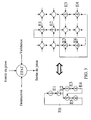
- Each state cell has three entries, token entry, destruction entry, and validation input, and a token output, as shown on the figure 1 .
- the token enters the cell state where it is stored. If validation is enabled then the token is transferred to the exit. If the destruction command is enabled, the token is removed from the status cell and the validation has no effect.
- the reconfiguration here consists in linking the state cells together so as to model the Petri graphs associated with the application.
- the control part of an application is used to make the connections between the state cells.
- the invention proposes to use a technology reconfigurable to translate the control part of an application into interconnects.
- the first example ( figure 3 ) illustrates a simple transposition between a Petri graph and its implementation using the state cell.
- the transposition consists of realizing the transfer paths of the token by connecting the state cells together (transmission connections).
- the token can not be simultaneously in cell number 5 and in cell number 3. To implement this Petri graph, it is necessary to use the destruction connections. As soon as one of the two events (E2 or E3) takes place, the token waiting for the other event is destroyed. Thus cells number 5 and 3 can not be validated at the same time.
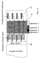
- the cells In order to be able to make any Petri graph, the cells must be fully interconnectable: one cell must be able to connect with all the others. If the structure has N states cells, then N 2 connectors 2 as shown on the figure 6a .
- each cell 1 can only connect to a limited number of cells, but each cell can serve as a connector to increase network connectivity as shown in FIG. Figure 6c .
- figure 7 shows a functional implementation of a state cell supporting indirect connections.
- All these primitives can be performed by each of the state cells.
- the sending of the primitives is however managed by an external control device.
- This controller is responsible for managing state cells. It must notably manage the sending of the primitives towards the cells in order to allow the construction of the graphs of Petri. It is also responsible for the release of resources for the use of the structure of the system of the invention as a memory cache (use described later).
- All state cells can be instructed to know which primitive to perform. If a state cell is not used, it is marked as free if not used.
- the first primitive consists of transmitting to a state cell the type of connection that it must carry out.
- each cell must be able to contain information relating to the connection that it must make.
- the cell must memorize the type of connection that it will have to establish (connection of transmission, validation or destruction).
- the second primitive is to connect to a new state cell.
- the state cell having to make this connection looks for among the free state cells of its neighborhood, that is to say those to which it can directly access. If a free cell is found, the connection is made. This requires that the cell be able to send a connection request to each of these neighbors and check their state of freedom. Thus, a connection request signal must be sent to the neighboring cells and each of them must provide a signal characteristic of its state (free or used).
- the fourth primitive is a security that avoids the blockage of the system due to the lack of free cells. It allows forcing the release of a state cell for reuse.
- a mechanism for collecting and distributing events is set up. Some cells are not connectable by other system states cells. These cells receive their chips directly from an event bus 33 and are called "event receivers".
- the event bus consists of all the signals that are associated with a transition in the Petri graphs. Validation connections can be established from these cells to feed the event structure.
- the references 30, 31 and 32 respectively represent: an event receiver, the used state cells and the free state cells.
- each place of the Petri graph corresponds an action to be performed. It is therefore necessary to set up a device for linking an action to a state cell. Each cell must therefore be able to signal to the structure integrating the system of the invention the presence of the token. In the same way, each cell must also indicate when it is used to model a place of the Petri graph, to allow the system to map to the appropriate action.
- a possible implementation of such a mechanism may be based on the use of a memory, as illustrated on the figure 11 .
- each cell of the system of the invention is associated with a memory box 40.
- each time a token moves to a new cell it activates the reading of the memory box associated with this cell.
- This memory has a reconfigurable data bus 41. Indeed, each memory slot can choose the portion of the data bus on which the data will pass through a configuration information 42.
- This configuration associated with each memory box is a binary code which allows you to specify the part of the data bus used for transfers. Thus, it is possible that several memory boxes are active at the same time without conflict.
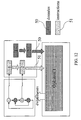
- two streams are generated by the propagation of tokens in the graph: a data stream and a flow of instructions. These two streams are sent to an operator who performs the processing by generating the events necessary for the associated Petri graph.
- a flow of instructions is generated and sent to each of the operators, the Petri graph being "parallelized” so as to generate several streams of data that will be used to supply the various operators of the targeted SIMD structure.
- different Petri graphs manage each of the operators, each of these graphs making it possible to generate the flow of instructions and data associated with each operator.
- the graphs can be synchronized with each other in order to coordinate the operators.
- Petri graphs avoids the implementation of a controller for the synchronization of operations during a SIMD or MIMD treatment.
- the MIMD mode is obtained by the ability to describe and browse several graphs in parallel. It is then possible by using the previously described configurable memory to generate parallel streams of data and instructions compatible with the targeted MIMD structure.
- the loading of the Petri graphs on the reconfigurable structure can be dynamic. Indeed, the progression of the tokens in the graphs is not incompatible with the loading of graphs. For example, for complex applications the whole graph can not fit on the structure.
- the system then functions like a cache: it keeps in memory the actions to be performed in the rest of the application. The operation of the covers as well as examples of conventional implementations are described below.
- the figure 15 discloses a four-level memory hierarchy that proceeds from processor 56 to central memory 52 through three cache levels L1 55, L2 54 and L3 53.
- the presence of the data or instruction is first verified. in the memory closest to the processor. If the data requested is not present we go down in the memory hierarchy until we find it.
- the mechanism of loading the data in the caches makes it possible to favor the use of the memory closest to the processor (cache L1).
- cache L1 Currently some processor architectures integrate L1 and L2.
- the system of the invention can be used in the implementation of caches. Since the petriery graph associated with an application may be too large to be integrated on the system, it must be cut into parts. The portion of the Petri graph stored on the system must therefore be dynamically updated according to the progress of the application. Some state cells may not be reachable during the execution of the application, which means that these state cells can no longer receive tokens. Each state cell constantly knows whether it is achievable or not. A device capable of deleting the non-reachable states cells is set up so as to release certain state cells to enable the loading of the sequence of the graph. This device must make it possible to balance the loading and unloading of the state cells. This mechanism is to be integrated in the external controller introduced during the definition of the primitives of the state cell.
- the unloading of the state cells is performed using the release primitive presented previously.
- the controller decides on the release of a state cell based on its reachability and a criterion reflecting the balance between loading and unloading state cells.
- the release of the state cell is achieved by the use of the release primitive. It can for example be implemented so as to maintain constant the relationship between the free state cells and the used state cells, in order to maintain sufficient routing resources.
- Each token transmission connection is coupled with a connection which makes it possible to know whether a state cell is accessible or not. Indeed the information that circulates on these connections reflects the presence or absence of a token upstream of the state cell considered. If there is a token upstream of the cell state it is reachable, otherwise the cell state will be considered unreachable.
- the figure 17 illustrates such a mechanism. On this FIG. 6 shows the reachability signal 60, the transmission connections 61, the non-attainable states 62, and the token 63.
Abstract
Description
La présente invention concerne un système reconfigurable basé sur la mise en oeuvre de graphes de Pétri.The present invention relates to a reconfigurable system based on the implementation of Petri graphs.
Tout traitement pouvant être décomposé en deux parties, une partie contrôle qui permet de décrire l'ordonnancement des opérations à accomplir, et une partie opérative qui réalise ces opérations, est-par la suite appelée "application".Any treatment that can be broken down into two parts, a control part that describes the scheduling of the operations to be performed, and an operative part that performs these operations, is subsequently called "application".
L'invention consiste à proposer un système pour la mise en oeuvre de la partie contrôle d'une application. Ce système est compatible avec les différents paradigmes de parallélisme (parallélisme de données, d'instructions ou de tâches), et peut être utilisé avec les différents type de calculateurs existants qu'ils soient synchrones ou asynchrones.The invention consists in proposing a system for implementing the control part of an application. This system is compatible with different paradigms of parallelism (parallelism of data, instructions or tasks), and can be used with different types of existing computers whether they are synchronous or asynchronous.
L'invention est basée sur l'utilisation de graphes de Pétri qui permettent de modéliser la partie contrôle des applications. Usuellement, ce type de modélisation est utilisé dans le domaine logiciel car elle permet d'effectuer la vérification formelle sur les applications comme décrit dans le document référencé [1] en fin de description. Les réseaux de Pétri sont aussi à la base de la programmation des automates et notamment des PLC ("programmable Logic Controler" ou "contrôleur logique programmable"), comme décrit dans le document référencé [2]. L'utilisation de cette modélisation pose un certain nombre de problèmes : notamment la taille de ces graphes augmente très rapidement avec la taille des applications. Les PLC sont généralement basés sur une solution logicielle associée à une unité de calcul classique.The invention is based on the use of Petri graphs which make it possible to model the control part of the applications. Usually, this type of modeling is used in the software domain because it makes it possible to carry out the formal verification on the applications as described in the referenced document [1] at the end of the description. Petri nets are also the basis for programming PLCs and especially PLCs ("Programmable Logic Control "or" programmable logic controller "), as described in the referenced document [2] The use of this modeling poses a certain number of problems: in particular the size of these graphs increases very rapidly with the size of the applications. are generally based on a software solution associated with a conventional computing unit.
Le document de référence [3] décrit un réseau logique asynchrone capable de mettre en oeuvre directement une spécification d'un système numérique par un graphe de Pétri.The reference document [3] describes an asynchronous logical network capable of directly implementing a specification of a digital system by a graph of Petri.
L'invention, a pour objet un système permettant la transposition directe de graphes de Pétri sur un support Matériel.The invention relates to a system for the direct transposition of Petri graphs on a material support.
La présente invention décrit un système reconfigurable défini dans la présente revendication 1. Des modes préférentiels de réalisation de l'invention sont définis dans les revendications dépendantes.The present invention describes a reconfigurable system defined in the
Le système de l'invention est conçu en utilisant le concept de la reconfigurabilité qui permet de pouvoir changer dynamiquement, c'est-à-dire en cours de fonctionnement, le graphe de contrôle d'une application. La reconfigurabilité permet d'envisager une solution matérielle pour la gestion de ces graphes. En effet, il est possible avec un tel système de charger des graphes de Pétri par portion, ce qui ne limite pas la taille des applications pouvant être traitées.The system of the invention is designed using the concept of reconfigurability that allows to change dynamically, that is to say during operation, the control graph of an application. Reconfigurability makes it possible to envisage a hardware solution for the management of these graphs. Indeed, it is possible with such a system to load Petri graphs per portion, which does not limit the size of the applications that can be processed.
-
La
figure 1 illustre les entrées/sorties d'une cellule état.Thefigure 1 illustrates the inputs / outputs of a state cell. -
La
figure 2 illustre les différents types de connexions entre cellules états.Thefigure 2 illustrates the different types of connections between state cells. -
La
figure 3 illustre la transposition d'un graphe de Pétri.Thefigure 3 illustrates the transposition of a Petri graph. -
La
figure 4 illustre la transposition d'un graphe de Pétri utilisant la destruction de jetons.Thefigure 4 illustrates the transposition of a Petri graph using the destruction of tokens. -
La
figure 5 illustre la synchronisation entre deux graphes de Pétri.Thefigure 5 illustrates the synchronization between two graphs of Petri. -
La
figure 6a illustre un réseau entièrement connecté.Thefigure 6a illustrates a fully connected network. -
La
figure 6b illustre un court-circuit qui permet d'utiliser la cellule état comme un connecteur.Thefigure 6b illustrates a short circuit that allows the state cell to be used as a connector. -
La
figure 6c illustre le nombre de connexions nécessaire qui est réduit par l'utilisation de connexions indirectes.TheFigure 6c illustrates the necessary number of connections that is reduced by using indirect connections. -
La
figure 7 illustre un exemple de mise en oeuvre fonctionnelle de la cellule état, le jeton mémorisé étant détruit après sa transmission.Thefigure 7 illustrates an example of functional implementation of the state cell, the memorized token being destroyed after transmission. -
La
figure 8 illustre un exemple de connexion entre deux cellules états existantes, avec :- (a) marquage des cellules états source et destinataire,
- (b) recherche de la cellule état destinataire,
- (c) destruction des connexions inutiles.
figure 8 illustrates an example of a connection between two existing state cells, with:- (a) marking the source and recipient state cells,
- (b) search for the recipient state cell,
- (c) destruction of unnecessary connections.
-
La
figure 9 illustre le séquencement des étapes de la connexion automatique entre deux cellules.Thefigure 9 illustrates the sequencing of the steps of the automatic connection between two cells. -
La
figure 10 illustre l'alimentation en évènements d'un graphe de Pétri mis en oeuvre dans le système de l'invention.Thefigure 10 illustrates the event feed of a Petri graph implemented in the system of the invention. -
La
figure 11 illustre une structure de la mémoire associée aux graphes de Pétri mis en oeuvre dans le système de l'invention.Thefigure 11 illustrates a structure of the memory associated with the graphs of Petri implemented in the system of the invention. -
La
figure 12 illustre la mise en oeuvre du système de l'invention pour un traitement SISD ("single instruction stream single data stream" ou "simple flot de données simple flot d'instructions").Thefigure 12 illustrates the implementation of the system of the invention for SISD processing ("single stream stream data stream instruction" or "simple stream of simple flow of instructions" data). -
La
figure 13 illustre la mise en oeuvre du système de l'invention pour un traitement SIMD ("single instructions stream multiple data stream" ou "simple flot d'instructions multiple flot de données").Thefigure 13 illustrates the implementation of the system of the invention for SIMD processing ("single instructions stream multiple data stream" or "single stream of instructions multiple data stream"). -
La
figure 14 illustre la mise en oeuvre du système de l'invention pour un traitement MIMD ("multiple instructions stream multiple data stream" ou "multiple flot d'instructions multiple flot de données").Thefigure 14 illustrates the implementation of the system of the invention for MIMD processing ("multiple instructions stream multiple data stream" or "multiple flow instruction multiple data stream"). -
La
figure 15 illustre un exemple d'une hiérarchie mémoire classique.Thefigure 15 illustrates an example of a classic memory hierarchy. -
La
figure 16 illustre un cache du type "2-way set-associative cache" ou "cache à deux ensemble associatifs",Thefigure 16 illustrates a cache of the type "2-way set-associative cache" or "cache with two associative sets", -
La
figure 17 illustre une accessibilité d'un état.Thefigure 17 illustrates accessibility of a state.
L'invention propose d'utiliser une représentation sous forme de graphes de Pétri pour modéliser une application. Les graphes de Pétri supportés par l'invention doivent répondre à trois critères :
- Il y a un seul jeton par place,
- Si deux jetons se rejoignent, il n'en forme plus qu'un,
- Un jeton peut être transmis vers plusieurs places.
- There is only one token per place,
- If two tokens meet, it is one,
- A token can be transmitted to several places.
Une application peut être modélisée par ces graphes de Pétri. En effet, chaque place du graphe de Pétri peut être liée à une action et la transition entre deux places est validée par des évènements de contrôle. Ces évènements de contrôle servent à faire progresser les jetons dans les graphes de Pétri mis en oeuvre dans le système de l'invention. Ils peuvent provenir de différents modules selon l'application à modéliser. A titre d'exemple, il peut s'agir des sorties d'un capteur ou des drapeaux d'événements d'une ALU (unité arithmétique et logique).An application can be modeled by these graphs of Petri. Indeed, each place of the Petri graph can be linked to an action and the transition between two places is validated by control events. These control events are used to advance the chips in the graphs of Petri implemented in the system of the invention. They can come from different modules depending on the application to be modeled. For example, it can be the outputs of a sensor or event flags of an ALU (arithmetic and logic unit).
L'invention consiste donc en un système reconfigurable permettant la modélisation de graphes de Pétri : un ou plusieurs jetons vont circuler dans le système de l'invention en fonction d'évènements. Les places, qui reçoivent les jetons, déterminent les actions à accomplir.The invention therefore consists of a reconfigurable system for modeling Petri graphs: one or more chips will circulate in the system of the invention as a function of events. Places, which receive the chips, determine the actions to be performed.
Chaque place du réseau de Pétri correspond à une cellule de base du système de l'invention. Cette cellule, appelée par la suite "cellule état", peut :
- recevoir un jeton,
- être activée par l'arrivée d'un jeton,
- transmettre son jeton vers d'autres cellules états si elle a été activée par l'arrivé d'un signal de validation,
- détruire son jeton sans le transmettre par l'arrivée d'une demande de "reset" ou de mise à zéro.
- receive a token,
- be activated by the arrival of a token,
- transmit its token to other status cells if it has been activated by the arrival of a validation signal,
- destroy his token without transmitting it by the arrival of a request for "reset" or reset.
Chaque cellule état possède trois entrées, entrée du jeton, entrée de destruction et entrée de validation, et une sortie de jeton, comme illustré sur la
Le jeton entre dans la cellule état où il est stocké. Si la validation est activée alors le jeton est transféré vers la sortie. Si la commande de destruction est activée, le jeton est supprimé de la cellule état et la validation n'a plus d'effet.The token enters the cell state where it is stored. If validation is enabled then the token is transferred to the exit. If the destruction command is enabled, the token is removed from the status cell and the validation has no effect.
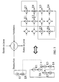
Ces cellules états sont dupliquées en très grand nombre et sont connectées les unes aux autres par un réseau reconfigurable de connecteurs. Trois types de connexions entre deux cellules états existent :
- Connexion de transmission : indique l'état (ou les états) suivant(s).
- Connexion de validation : permet de valider la transmission du jeton.
- Connexion de destruction : permet de détruire un jeton.
- Transmission Connection: Indicates the next status (or states).
- Validation connection: allows to validate the transmission of the token.
- Destruction Connection: Destroys a token.
La reconfiguration consiste ici à relier les cellules états entre elles de façon à modéliser les graphes de Pétri associés à l'application.The reconfiguration here consists in linking the state cells together so as to model the Petri graphs associated with the application.
La
- 1. une connexion de transmission,
- 2. une connexion de validation,
- 3. une connexion de destruction,
avec E_J : entrée jeton
S_J : sortie jeton
D : destruction
V : validation
- 1. a transmission connection,
- 2. a validation connection,
- 3. a destruction connection,
with E_J: token entry
S_J: Token output
D: destruction
V: validation
Trois exemples de transpositions de graphe de Pétri sont données respectivement dans les
La partie contrôle d'une application sert à réaliser les connexions entre les cellules états. L'invention propose d'utiliser une technologie reconfigurable afin de traduire la partie contrôle d'une application sous forme d'interconnexions.The control part of an application is used to make the connections between the state cells. The invention proposes to use a technology reconfigurable to translate the control part of an application into interconnects.
Le premier exemple (
Le second exemple (
- E2 : dans ce cas le jeton est transmis à la cellule numéro 5.
- E3 : dans ce cas le jeton est transmis à la cellule numéro 3.
- E2: in this case the token is transmitted to
cell number 5. - E3: in this case the token is transmitted to
cell number 3.
Le jeton ne peut pas être simultanément dans la cellule numéro 5 et dans la cellule numéro 3. Pour mettre en oeuvre ce graphe de Pétri, il est nécessaire d'utiliser les connexions de destruction. Dès qu'un des deux évènements (E2 ou E3) a lieu, le jeton en attente de l'autre évènement est détruit. Ainsi les cellules numéros 5 et 3 ne peuvent pas être validées en même temps.The token can not be simultaneously in
Dans le troisième exemple (
Afin de pouvoir réaliser n'importe quel graphe de Pétri, il faut que les cellules soient entièrement interconnectables : une cellule doit pouvoir se connecter avec toutes les autres. Si la structure possède N cellules états, il faut donc N2 connecteurs 2 comme illustré sur la
Pour limiter le nombre de connecteurs 2 nécessaires, un nouveau type de connexion est ajouté aux trois précédents. La cellule état est modifiée en réalisant une connexion entre l'entrée et la sortie du jeton au moyen d'un multiplexeur 5, comme illustré sur la
A titre d'exemple, la
Afin de faciliter la mise en oeuvre des graphes de Pétri, la réalisation des connexions entre les cellules états est automatisée. Pour ce faire, chaque cellule état peut accomplir des actions de base appelées "primitives". Quatre primitives permettent de construire facilement un graphe de Pétri :
- Choix de la connexion à réaliser.
- Réalisation d'une connexion vers une cellule état libre.
- Réalisation d'une connexion vers une cellule état utilisée.
- Libération (déconnexion) de la cellule état.
- Choice of the connection to realize.
- Making a connection to a free state cell.
- Making a connection to a used state cell.
- Release (disconnect) from the status cell.
Toutes ces primitives peuvent être effectuées par chacune des cellules d'états. L'envoi des primitives est par contre géré par un dispositif de contrôle externe. Ce contrôleur est chargé de la gestion des cellules états. Il doit notamment gérer l'envoi des primitives vers les cellules afin de permettre la construction des graphes de Pétri. Il est aussi responsable de la libération des ressources en vue de l'utilisation de la structure du système de l'invention comme un cache mémoire (utilisation décrite par la suite).All these primitives can be performed by each of the state cells. The sending of the primitives is however managed by an external control device. This controller is responsible for managing state cells. It must notably manage the sending of the primitives towards the cells in order to allow the construction of the graphs of Petri. It is also responsible for the release of resources for the use of the structure of the system of the invention as a memory cache (use described later).
Toutes les cellules états peuvent recevoir des instructions afin de connaître la primitive à effectuer. Si une cellule état n'est pas utilisé, elle est marquée comme libre sinon comme utilisée.All state cells can be instructed to know which primitive to perform. If a state cell is not used, it is marked as free if not used.
La première primitive consiste à transmettre à une cellule état le type de connexion qu'elle doit réaliser. Ainsi chaque cellule doit être en mesure de contenir une information relatant la connexion qu'elle doit réaliser. La cellule doit mémoriser le type de connexion qu'elle va devoir établir (connexion de transmission, de validation ou de destruction).The first primitive consists of transmitting to a state cell the type of connection that it must carry out. Thus, each cell must be able to contain information relating to the connection that it must make. The cell must memorize the type of connection that it will have to establish (connection of transmission, validation or destruction).
La seconde primitive consiste à se connecter à une nouvelle cellule état. La cellule état devant réaliser cette connexion cherche parmi les cellules états libres de son voisinage, c'est-à-dire celles auxquelles elle peut accéder de manière directe. Si une cellule libre est trouvée, la connexion est réalisée. Ceci impose que la cellule soit en mesure d'envoyer une requête de connexion vers chacune de ces voisines et de vérifier leur état de liberté. Ainsi, un signal de demande de connexion doit être envoyé vers les cellules voisines et chacune d'elles doit fournir un signal caractéristique de son état (libre ou utilisée).The second primitive is to connect to a new state cell. The state cell having to make this connection looks for among the free state cells of its neighborhood, that is to say those to which it can directly access. If a free cell is found, the connection is made. This requires that the cell be able to send a connection request to each of these neighbors and check their state of freedom. Thus, a connection request signal must be sent to the neighboring cells and each of them must provide a signal characteristic of its state (free or used).
La troisième primitive consiste à réaliser automatiquement les connexions entre deux états. Cette primitive est réalisée en trois étapes successives comme illustré sur la
- 1. Les deux cellules à connecter entre elles sont identifiées. La cellule état qui tente d'établir la connexion est appelée
source 15, la seconde est qualifiée de destinataire 16. La cellule destinataire est marquée comme libre. Hormis la cellule source et la cellule destinataire, toutes les cellules réalisent des connexions indirectes (figure 8a ). - 2. Depuis la cellule état source, des connexions sont établies vers les cellules libres de son voisinage. Ce processus est répété depuis chacune des nouvelles cellules connectées jusqu'à ce que la cellule destinataire soit trouvée. Cette étape requière que chaque cellule puisse connecter toutes les cellules libres de son voisinage en leur imposant de réaliser la même opération (
figure 8b ). - 3. Les connexions inutiles sont détruites. Il ne subsiste alors que la connexion désirée. Afin de permettre cette dernière étape, la cellule destinataire envoie un signal de validation. Toutes les cellules qui ne reçoivent pas ce signal peuvent alors être déconnectées. Il faut s'assurer que la cellule source a bien reçu le signal de la cellule destinataire avant de détruire les connexions inutiles de façon à bien identifier les cellules états à détruire. Il est donc nécessaire que les cellules connectées au cours de la réalisation de cette primitive puissent recevoir le signal de la cellule destinataire (
figure 8c ).
- 1. The two cells to be connected to each other are identified. The state cell that attempts to establish the connection is called
source 15, the second is calledrecipient 16. The destination cell is marked as free. Apart from the source cell and the recipient cell, all the cells make indirect connections (figure 8a ). - 2. From the source state cell, connections are made to free cells in its neighborhood. This process is repeated from each of the new connected cells until the recipient cell is found. This step requires that each cell can connect all cells free from its neighborhood by imposing on them the same operation (
figure 8b ). - 3. Unnecessary connections are destroyed. There remains only the desired connection. In order to allow this last step, the destination cell sends a validation signal. Any cells that do not receive this signal can then be disconnected. It must be ensured that the source cell has received the signal from the recipient cell before destroying unnecessary connections in order to identify the cell states to be destroyed. It is therefore necessary that the cells connected during the production of this primitive can receive the signal from the destination cell (
figure 8c ).
Chacune des étapes de la troisième primitive est réalisée par les cellules. Par contre le séquencement de ces étapes nécessite l'intervention du contrôleur externe évoqué précédemment. Le graphe de fonctionnement qui gère ce processus et qui devra être intégré au contrôleur externe est illustré sur la
- initialisation de la cellule source et de la cellule destinataire (20),
- établissement par toute cellule récemment connectée de connexions de transmission vers les cellules voisines libres, en commençant par la cellule source (21), jusqu'à l'obtention de la cellule destinataire (22),
- attente (23), jusqu'à la réception par la cellule source du signal de la cellule destinataire (24),
- déconnexion de toute cellule connectée qui ne reçoit pas le signal source et le signal destinataire (25).
- initialization of the source cell and the destination cell (20),
- establishment by any newly connected cell of transmission connections to the neighboring free cells, starting with the source cell (21), until the destination cell (22) is obtained,
- waiting (23), until reception by the source cell of the signal of the destination cell (24),
- disconnection of any connected cell that does not receive the source signal and the destination signal (25).
La quatrième primitive est une sécurité qui permet d'éviter le blocage du système dû au manque de cellules libres. Elle autorise le forçage de la libération d'une cellule état en vue de sa réutilisation.The fourth primitive is a security that avoids the blockage of the system due to the lack of free cells. It allows forcing the release of a state cell for reuse.
Afin d'alimenter le système de l'invention en évènements, comme illustré sur la
A chaque place du graphe de Pétri correspond une action à accomplir. Il faut donc mettre en place un dispositif permettant de lier une action à une cellule état. Chaque cellule doit donc être en mesure de signaler à la structure intégrant le système de l'invention la présence du jeton. De la même façon, chaque cellule doit aussi signaler quand elle est utilisée pour modéliser une place du graphe de Pétri, de façon à permettre au système la mise en correspondance avec l'action appropriée.At each place of the Petri graph corresponds an action to be performed. It is therefore necessary to set up a device for linking an action to a state cell. Each cell must therefore be able to signal to the structure integrating the system of the invention the presence of the token. In the same way, each cell must also indicate when it is used to model a place of the Petri graph, to allow the system to map to the appropriate action.
Une mise en oeuvre possible d'un tel mécanisme peut être basée sur l'utilisation d'une mémoire, comme illustré sur la
Cette mémoire possède un bus de donnée reconfigurable 41. En effet, chaque case mémoire peut choisir la partie du bus de donnée sur laquelle la donnée va transiter grâce à une information de configuration 42. Cette configuration associée à chaque case mémoire est un code binaire qui permet de spécifier la partie du bus de donnée utilisée pour les transferts. Ainsi, il est possible que plusieurs cases mémoires soient actives en même temps sans conflit.This memory has a
La structure de graphes de Pétri associée avec cette mémoire permet de gérer le contrôle de nombreuses architectures parallèles qu'elles soient synchrones ou non. Des exemples pour un traitement SISD, SIMD et MIMD, sont présentés respectivement dans les
Pour le traitement SISD deux flots sont générés par la propagation des jetons dans le graphe : un flot de données et un flot d'instructions. Ces deux flots sont envoyés vers un opérateur qui effectue le traitement en générant les évènements nécessaires au graphe de Pétri associé.For SISD processing two streams are generated by the propagation of tokens in the graph: a data stream and a flow of instructions. These two streams are sent to an operator who performs the processing by generating the events necessary for the associated Petri graph.
Pour le traitement SIMD, un flot d'instructions est généré et envoyé vers chacun des opérateurs, le graphe de Pétri étant "parallélisé" de façon à générer plusieurs flots de données qui serviront à alimenter les différents opérateurs de la structure SIMD ciblée.For SIMD processing, a flow of instructions is generated and sent to each of the operators, the Petri graph being "parallelized" so as to generate several streams of data that will be used to supply the various operators of the targeted SIMD structure.
Pour le traitement MIMD, des graphes de Pétri différents gèrent chacun des opérateurs, chacun de ces graphes permettant de générer les flots d'instructions et de données associés à chaque opérateur. Les graphes peuvent être synchronisés entre eux de manière à coordonner les opérateurs.For the MIMD processing, different Petri graphs manage each of the operators, each of these graphs making it possible to generate the flow of instructions and data associated with each operator. The graphs can be synchronized with each other in order to coordinate the operators.
L'utilisation des graphes de Pétri permet d'éviter la mise en oeuvre d'un contrôleur destiné à la synchronisation des opérations lors d'un traitement SIMD ou MIMD. Le mode MIMD est obtenu par la possibilité de décrire et de parcourir plusieurs graphes en parallèles. Il est alors possible en utilisant la mémoire configurable décrite précédemment de générer des flots de données et d'instructions parallèles compatibles avec la structure MIMD ciblée.The use of Petri graphs avoids the implementation of a controller for the synchronization of operations during a SIMD or MIMD treatment. The MIMD mode is obtained by the ability to describe and browse several graphs in parallel. It is then possible by using the previously described configurable memory to generate parallel streams of data and instructions compatible with the targeted MIMD structure.
Le chargement des graphes de Pétri sur la structure reconfigurable peut être dynamique. En effet, la progression des jetons dans les graphes n'est pas incompatible avec le chargement de graphes. Par exemple, pour des applications complexes l'ensemble du graphe ne peut pas tenir sur la structure. Le système fonctionne alors à la manière d'un cache : il garde en mémoire les actions à effectuer dans la suite de l'application. Le fonctionnement des caches ainsi que des exemples de mises en oeuvre classiques sont décrits dans la suite.The loading of the Petri graphs on the reconfigurable structure can be dynamic. Indeed, the progression of the tokens in the graphs is not incompatible with the loading of graphs. For example, for complex applications the whole graph can not fit on the structure. The system then functions like a cache: it keeps in memory the actions to be performed in the rest of the application. The operation of the covers as well as examples of conventional implementations are described below.
Afin de montrer les avantages apportés par la mise en oeuvre matérielle des graphes de Pétri, on va, à présent, considérer un état de l'art sur les caches. Le principe de fonctionnement de la hiérarchie mémoire de nombreux système est basé sur l'utilisation de caches. Ces caches dérivent du même schéma de base. Les différences entre les diverses architectures de hiérarchie mémoire reposent sur le nombre et la taille des caches utilisés ainsi que sur la gestion des données stockées. Le nombre de cache est compris entre 1 et 3 selon le système considéré. La taille des caches diminue quand on se rapproche du processeur ainsi les caches proches du processeur sont plus performant et possèdent des fréquences de fonctionnement compatibles avec les unités de calcul.In order to show the advantages brought by the physical implementation of the graphs of Petri, we will now consider a state of the art on the caches. The operating principle of the memory hierarchy of many systems is based on the use of caches. These caches derive from the same basic scheme. The differences between the various memory hierarchy architectures are based on the number and size of the caches used as well as the management of the stored data. The number of cache is between 1 and 3 depending on the system. The size of the caches decreases when one approaches the processor so caches close to the processor are more efficient and have operating frequencies compatible with the calculation units.
La
Le cache consiste en une mémoire qui contient une sous-partie de la mémoire centrale. L'adressage de cette.mémoire est réalisée par une sous-partie de l'adresse complète. La partie non utilisée de l'adresse sert à vérifier la validité de la donnée en mémoire. En effet la mémoire contient la donnée cachée ainsi qu'une clé permettant de reconstruire l'adresse complète de la donnée en mémoire centrale. La comparaison des deux clés va donc permettre de savoir si la donnée est valide ou non. Le mécanisme permettant d'associer une adresse absolue à une adresse de cache n'est pas une fonction bijective. C'est-à-dire qu'à une adresse de cache peut correspondre plusieurs adresses absolues qui sont qualifiées de concurrentes. Il existe deux grandes familles de cache :
- les caches de type "direct-mapped cache"
- les caches de type "N-way sent-associative cache" ou "cache à N ensembles associatifs" : dans ce type de mémoire il y a N mémoires qui cohabitent ce qui permet de stocker plusieurs adresses concurrentes comme illustré sur la
figure 16 . Le cache de type "direct-mapped cache" est équivalent au cas où N est égale à 1.
- the cache type "direct-mapped cache"
- the type cache "N-way sent-associative cache" or "cache with N associative sets": in this type of memory there are N memories that coexist which makes it possible to store several concurrent addresses as illustrated on the
figure 16 . The cache type "direct-mapped cache" is equivalent to the case where N is equal to 1.
Cette hiérarchie mémoire pose un certain nombre de problèmes :
- toutes les données stockées ne sont pas forcement utilisées,
- rallongement du temps d'accès mémoire,
- problème de cohérence entre les différentes mémoires,
- synchronisation obligatoire,
- accès séquentiels aux données,
La mise en oeuvre directe des graphes de Pétri permet de résoudre certains de ces problème : - Toutes les données stockées sont pertinentes et ont une probabilité d'être utilisées.
- L'accès mémoire n'est pas forcement séquentiel. Plusieurs données peuvent être accédées en même temps.
- La structure peut être utilisée par des systèmes synchrones ou asynchrones. La structure peut même être sollicitée par des systèmes n'ayant pas les mêmes mécanismes de synchronisation.
- all stored data is not necessarily used,
- lengthening the memory access time,
- problem of coherence between the different memories,
- mandatory synchronization,
- sequential access to data,
The direct implementation of Petri graphs solves some of these problems: - All stored data is relevant and has a probability of being used.
- The memory access is not necessarily sequential. Several data can be accessed at the same time.
- The structure can be used by synchronous or asynchronous systems. The structure can even be solicited by systems that do not have the same synchronization mechanisms.
Le système de l'invention peut être utilisé dans la mise en oeuvre de caches. Le graphe de Pétri associé à une application pouvant être trop volumineux pour être intégré sur le système, il est nécessaire de la découper en parties. La partie du graphe de Pétri stockée sur le système doit donc être dynamiquement remise à jour en fonction de l'avancement de l'application. Certaines cellules états peuvent au cours de l'exécution de l'application ne plus être atteignables, cela signifie que ces cellules états ne peuvent plus recevoir de jetons. Chaque cellule état connaît en permanence si elle est atteignable ou non. Un dispositif capable de supprimer les cellules états non-atteignables est donc mis en place de façon à libérer certaines cellules états pour permettre le chargement de la suite du graphe. Ce dispositif doit permettre d'équilibrer le chargement et le déchargement des cellules états. Ce mécanisme est à intégrer dans le contrôleur externe introduit lors de la définition des primitives de la cellule état. Le déchargement des cellules états est réalisé en utilisant la primitive de libération présentée précédemment. Le contrôleur décide de la libération d'une cellule état en se basant sur son atteignabilité et sur un critère reflétant l'équilibre entre le chargement et le déchargement des cellules états. La libération de la cellule état est réalisée par l'utilisation de la primitive de libération. Il peut par exemple être mis en oeuvre de manière à maintenir constant le rapport entre les cellules états libres et les cellules états utilisées, ceci dans le but de maintenir des ressources de routage suffisantes.The system of the invention can be used in the implementation of caches. Since the petriery graph associated with an application may be too large to be integrated on the system, it must be cut into parts. The portion of the Petri graph stored on the system must therefore be dynamically updated according to the progress of the application. Some state cells may not be reachable during the execution of the application, which means that these state cells can no longer receive tokens. Each state cell constantly knows whether it is achievable or not. A device capable of deleting the non-reachable states cells is set up so as to release certain state cells to enable the loading of the sequence of the graph. This device must make it possible to balance the loading and unloading of the state cells. This mechanism is to be integrated in the external controller introduced during the definition of the primitives of the state cell. The unloading of the state cells is performed using the release primitive presented previously. The controller decides on the release of a state cell based on its reachability and a criterion reflecting the balance between loading and unloading state cells. The release of the state cell is achieved by the use of the release primitive. It can for example be implemented so as to maintain constant the relationship between the free state cells and the used state cells, in order to maintain sufficient routing resources.
Chaque connexion de transmission de jeton est couplée avec une connexion qui permet de connaître si une cellule état est accessible ou non. En effet l'information qui circule sur ces connexions reflète la présence ou l'absence d'un jeton en amont de la cellule état considérée. S'il y a un jeton en amont de la cellule état il est atteignable, dans le cas contraire la cellule état sera considérée comme non-atteignable. La
-
[1] "
Petri net theory and the modelling of systems" de James L. Peterson (1981, Practice Hall, ISBN: 0136619835 Petri net theory and the modeling of systems "by James L. Peterson (1981, Practice Hall, ISBN: 0136619835 -
[2] "
Introduction to programmable logic controllers" " de Gary Dunning (deuxième édition, 1998, Delmas, ISBN: 0827378661 Introduction to programmable logic controllers "by Gary Dunning (second edition, 1998, Delmas, ISBN: 0827378661 -
[3] Brevet
US-A-4 068 214 US-A-4,068,214
Claims (6)
- Reconfigurable system for physically implementing the control part of an application comprising a control part and an operative part, said control part scheduling the operations to be carried out by the operative part, characterised in that it comprises:- a set of N physical state cells which are completely interconnectable, N being an integer greater than 1, each cell corresponding to a place on the Petri graph associated with said application, being able to connect to all the other cells and optionally containing a token, each cell also having a token input, a token destruction input, a token output and a validation input, each cell being programmed to store any token received at its token input, to destroy its token without transmitting it once its token destruction input has been activated and to transmit its token to any other cell connected to said token output once its validation input has been activated;- a reconfigurable network of connectors able to interconnect said cells, the token output of a cell being connectable to the token input of another cell via a first connection called a transfer connection, to the validation input of said other cell via a second connection called a validation connection, and to the destruction input of said other cell via a third connection called a destruction connection.
- System according to claim 1, wherein a multiplexer (5) connects the token input and the token output in each state cell, thus making it possible to use the state cell as a connector.
- System according to claim 1, wherein each state cell is able to implement all the following primitives in order to construct a Petri graph:- choice of the connection to be made,- connection to a free state cell,- connection to a used state cell,- disconnection from the state cell,
the connections between the state cells being made in an automated manner. - System according to claim 1, comprising event receiver cells (30) connected so as to receive their tokens directly from an event bus (33), said event receiver cells (30) not being connectable via the other state cells of the system.
- System according to claim 1, wherein each state cell is connected to a memory cache (40) of a memory which has a reconfigurable data bus.
- System according to any one of the preceding claims, wherein each state cell is able to permanently recognise whether it is accessible or inaccessible.
Applications Claiming Priority (3)
| Application Number | Priority Date | Filing Date | Title |
|---|---|---|---|
| FR0204396 | 2002-04-09 | ||
| FR0204396A FR2838222B1 (en) | 2002-04-09 | 2002-04-09 | RECONFIGURABLE CONTROL SYSTEM BASED ON THE MATERIAL IMPLEMENTATION OF PETRI GRAPHICS |
| PCT/FR2003/001086 WO2003085522A2 (en) | 2002-04-09 | 2003-04-07 | Reconfigurable control system based on hardware implementation of petri graphs |
Publications (2)
| Publication Number | Publication Date |
|---|---|
| EP1493083A2 EP1493083A2 (en) | 2005-01-05 |
| EP1493083B1 true EP1493083B1 (en) | 2009-09-30 |
Family
ID=28052226
Family Applications (1)
| Application Number | Title | Priority Date | Filing Date |
|---|---|---|---|
| EP03740574A Expired - Lifetime EP1493083B1 (en) | 2002-04-09 | 2003-04-07 | Reconfigurable control system based on hardware implementation of petri graphs |
Country Status (7)
| Country | Link |
|---|---|
| US (1) | US7499843B2 (en) |
| EP (1) | EP1493083B1 (en) |
| JP (1) | JP4349914B2 (en) |
| AT (1) | ATE444521T1 (en) |
| DE (1) | DE60329479D1 (en) |
| FR (1) | FR2838222B1 (en) |
| WO (1) | WO2003085522A2 (en) |
Family Cites Families (7)
| Publication number | Priority date | Publication date | Assignee | Title |
|---|---|---|---|---|
| US4068214A (en) * | 1976-02-03 | 1978-01-10 | Massachusetts Institute Of Technology | Asynchronous logic array |
| USRE31287E (en) * | 1976-02-03 | 1983-06-21 | Massachusetts Institute Of Technology | Asynchronous logic array |
| US4866605A (en) * | 1984-11-05 | 1989-09-12 | Hitachi, Ltd. | System function simulation method and apparatus therefor using Petri net symbols |
| US4845633A (en) * | 1985-12-02 | 1989-07-04 | Apple Computer Inc. | System for programming graphically a programmable, asynchronous logic cell and array |
| US4700187A (en) * | 1985-12-02 | 1987-10-13 | Concurrent Logic, Inc. | Programmable, asynchronous logic cell and array |
| US6476814B1 (en) * | 1998-06-25 | 2002-11-05 | Wordgraph, Inc. | Display structure for representation of complex systems |
| US6789054B1 (en) * | 1999-04-25 | 2004-09-07 | Mahmoud A. Makhlouf | Geometric display tools and methods for the visual specification, design automation, and control of adaptive real systems |
-
2002
- 2002-04-09 FR FR0204396A patent/FR2838222B1/en not_active Expired - Fee Related
-
2003
- 2003-04-07 AT AT03740574T patent/ATE444521T1/en not_active IP Right Cessation
- 2003-04-07 US US10/508,709 patent/US7499843B2/en not_active Expired - Fee Related
- 2003-04-07 JP JP2003582641A patent/JP4349914B2/en not_active Expired - Fee Related
- 2003-04-07 WO PCT/FR2003/001086 patent/WO2003085522A2/en active Application Filing
- 2003-04-07 EP EP03740574A patent/EP1493083B1/en not_active Expired - Lifetime
- 2003-04-07 DE DE60329479T patent/DE60329479D1/en not_active Expired - Lifetime
Also Published As
| Publication number | Publication date |
|---|---|
| US7499843B2 (en) | 2009-03-03 |
| FR2838222A1 (en) | 2003-10-10 |
| WO2003085522A3 (en) | 2004-04-01 |
| DE60329479D1 (en) | 2009-11-12 |
| FR2838222B1 (en) | 2005-02-18 |
| EP1493083A2 (en) | 2005-01-05 |
| ATE444521T1 (en) | 2009-10-15 |
| US20050149308A1 (en) | 2005-07-07 |
| JP2005527897A (en) | 2005-09-15 |
| WO2003085522A2 (en) | 2003-10-16 |
| JP4349914B2 (en) | 2009-10-21 |
Similar Documents
| Publication | Publication Date | Title |
|---|---|---|
| EP0597028B1 (en) | System architecture having parallel processor array | |
| CN107450981A (en) | A kind of block chain common recognition method and apparatus | |
| EP0020202B1 (en) | Multiprocessing system for signal treatment | |
| WO2007051935A1 (en) | Method and system for conducting intensive multitask and multiflow calculation in real-time | |
| EP0160028B1 (en) | Device and process for a fast and stable storage of data | |
| FR2737030A1 (en) | METHOD FOR TRANSFERRING MESSAGES IN A MULTINODAL COMPUTER SYSTEM | |
| EP0646875B1 (en) | Method and system of interconnection to manage messages in a processors network with a parallel structure | |
| EP3217290A1 (en) | System on chip and method for data exchange between calculation nodes of such a system on chip | |
| FR2927437A1 (en) | MULTIPROCESSOR COMPUTER SYSTEM | |
| EP0524089B1 (en) | Software structure for a data processing system, especially for a telecommunications system | |
| EP2254066A1 (en) | Method supporting the realisation and validation of an avionic platform | |
| EP2507712B1 (en) | System for direct data transfer between memories of plurality of elements of this system | |
| EP1493083B1 (en) | Reconfigurable control system based on hardware implementation of petri graphs | |
| EP2278466A1 (en) | Apparatus and method for the distributed execution of digital data processing | |
| FR2902211A1 (en) | Complex system stimulating method, involves constructing models of complex system, where each model comprises hierarchized assembly of modelized components that are instance of object class belonging to determined object class assembly | |
| WO2013110816A2 (en) | Method of using a shared memory | |
| EP2208143B1 (en) | Structure and method for saving and retrieving data | |
| EP2666092B1 (en) | Multi-core system and data coherency method | |
| EP0333537A1 (en) | Digital signal-processing device | |
| FR2707777A1 (en) | Computer system with shared memory. | |
| EP0113272B1 (en) | Modular nodal communication network | |
| FR2742894A1 (en) | Network exchange of data between multiple processors, memories and peripherals | |
| EP0797153A1 (en) | Information handling device comprising a plurality of parallel processors | |
| EP0965082A1 (en) | Computer equipment consisting of a plurality of interconnected modules and method for optimising such computer resources | |
| FR2642252A1 (en) | Circuit interconnection unit, especially of the crossbar type, process for employing a circuit interconnection unit and uses of a circuit interconnection unit |
Legal Events
| Date | Code | Title | Description |
|---|---|---|---|
| PUAI | Public reference made under article 153(3) epc to a published international application that has entered the european phase |
Free format text: ORIGINAL CODE: 0009012 |
|
| 17P | Request for examination filed |
Effective date: 20040920 |
|
| AK | Designated contracting states |
Kind code of ref document: A2 Designated state(s): AT BE BG CH CY CZ DE DK EE ES FI FR GB GR HU IE IT LI LU MC NL PT RO SE SI SK TR |
|
| RAP1 | Party data changed (applicant data changed or rights of an application transferred) |
Owner name: COMMISSARIAT A L'ENERGIE ATOMIQUE |
|
| 17Q | First examination report despatched |
Effective date: 20070214 |
|
| GRAP | Despatch of communication of intention to grant a patent |
Free format text: ORIGINAL CODE: EPIDOSNIGR1 |
|
| RIC1 | Information provided on ipc code assigned before grant |
Ipc: G06F 15/80 20060101ALI20090417BHEP Ipc: G06F 9/44 20060101AFI20090417BHEP Ipc: G06F 17/50 20060101ALI20090417BHEP |
|
| GRAS | Grant fee paid |
Free format text: ORIGINAL CODE: EPIDOSNIGR3 |
|
| GRAA | (expected) grant |
Free format text: ORIGINAL CODE: 0009210 |
|
| AK | Designated contracting states |
Kind code of ref document: B1 Designated state(s): AT BE BG CH CY CZ DE DK EE ES FI FR GB GR HU IE IT LI LU MC NL PT RO SE SI SK TR |
|
| REG | Reference to a national code |
Ref country code: CH Ref legal event code: EP Ref country code: GB Ref legal event code: FG4D Free format text: NOT ENGLISH |
|
| REG | Reference to a national code |
Ref country code: IE Ref legal event code: FG4D |
|
| REF | Corresponds to: |
Ref document number: 60329479 Country of ref document: DE Date of ref document: 20091112 Kind code of ref document: P |
|
| PG25 | Lapsed in a contracting state [announced via postgrant information from national office to epo] |
Ref country code: SE Free format text: LAPSE BECAUSE OF FAILURE TO SUBMIT A TRANSLATION OF THE DESCRIPTION OR TO PAY THE FEE WITHIN THE PRESCRIBED TIME-LIMIT Effective date: 20090930 |
|
| PG25 | Lapsed in a contracting state [announced via postgrant information from national office to epo] |
Ref country code: SI Free format text: LAPSE BECAUSE OF FAILURE TO SUBMIT A TRANSLATION OF THE DESCRIPTION OR TO PAY THE FEE WITHIN THE PRESCRIBED TIME-LIMIT Effective date: 20090930 |
|
| PG25 | Lapsed in a contracting state [announced via postgrant information from national office to epo] |
Ref country code: RO Free format text: LAPSE BECAUSE OF FAILURE TO SUBMIT A TRANSLATION OF THE DESCRIPTION OR TO PAY THE FEE WITHIN THE PRESCRIBED TIME-LIMIT Effective date: 20090930 Ref country code: CZ Free format text: LAPSE BECAUSE OF FAILURE TO SUBMIT A TRANSLATION OF THE DESCRIPTION OR TO PAY THE FEE WITHIN THE PRESCRIBED TIME-LIMIT Effective date: 20090930 Ref country code: EE Free format text: LAPSE BECAUSE OF FAILURE TO SUBMIT A TRANSLATION OF THE DESCRIPTION OR TO PAY THE FEE WITHIN THE PRESCRIBED TIME-LIMIT Effective date: 20090930 Ref country code: ES Free format text: LAPSE BECAUSE OF FAILURE TO SUBMIT A TRANSLATION OF THE DESCRIPTION OR TO PAY THE FEE WITHIN THE PRESCRIBED TIME-LIMIT Effective date: 20100110 Ref country code: PT Free format text: LAPSE BECAUSE OF FAILURE TO SUBMIT A TRANSLATION OF THE DESCRIPTION OR TO PAY THE FEE WITHIN THE PRESCRIBED TIME-LIMIT Effective date: 20100201 |
|
| REG | Reference to a national code |
Ref country code: IE Ref legal event code: FD4D |
|
| PG25 | Lapsed in a contracting state [announced via postgrant information from national office to epo] |
Ref country code: CY Free format text: LAPSE BECAUSE OF FAILURE TO SUBMIT A TRANSLATION OF THE DESCRIPTION OR TO PAY THE FEE WITHIN THE PRESCRIBED TIME-LIMIT Effective date: 20090930 Ref country code: SK Free format text: LAPSE BECAUSE OF FAILURE TO SUBMIT A TRANSLATION OF THE DESCRIPTION OR TO PAY THE FEE WITHIN THE PRESCRIBED TIME-LIMIT Effective date: 20090930 |
|
| PG25 | Lapsed in a contracting state [announced via postgrant information from national office to epo] |
Ref country code: AT Free format text: LAPSE BECAUSE OF FAILURE TO SUBMIT A TRANSLATION OF THE DESCRIPTION OR TO PAY THE FEE WITHIN THE PRESCRIBED TIME-LIMIT Effective date: 20090930 |
|
| PG25 | Lapsed in a contracting state [announced via postgrant information from national office to epo] |
Ref country code: DK Free format text: LAPSE BECAUSE OF FAILURE TO SUBMIT A TRANSLATION OF THE DESCRIPTION OR TO PAY THE FEE WITHIN THE PRESCRIBED TIME-LIMIT Effective date: 20090930 Ref country code: IE Free format text: LAPSE BECAUSE OF FAILURE TO SUBMIT A TRANSLATION OF THE DESCRIPTION OR TO PAY THE FEE WITHIN THE PRESCRIBED TIME-LIMIT Effective date: 20090930 |
|
| PLBE | No opposition filed within time limit |
Free format text: ORIGINAL CODE: 0009261 |
|
| STAA | Information on the status of an ep patent application or granted ep patent |
Free format text: STATUS: NO OPPOSITION FILED WITHIN TIME LIMIT |
|
| 26N | No opposition filed |
Effective date: 20100701 |
|
| PG25 | Lapsed in a contracting state [announced via postgrant information from national office to epo] |
Ref country code: GR Free format text: LAPSE BECAUSE OF FAILURE TO SUBMIT A TRANSLATION OF THE DESCRIPTION OR TO PAY THE FEE WITHIN THE PRESCRIBED TIME-LIMIT Effective date: 20091231 |
|
| BERE | Be: lapsed |
Owner name: COMMISSARIAT A L'ENERGIE ATOMIQUE Effective date: 20100430 |
|
| PG25 | Lapsed in a contracting state [announced via postgrant information from national office to epo] |
Ref country code: MC Free format text: LAPSE BECAUSE OF NON-PAYMENT OF DUE FEES Effective date: 20100430 |
|
| REG | Reference to a national code |
Ref country code: CH Ref legal event code: PL |
|
| PG25 | Lapsed in a contracting state [announced via postgrant information from national office to epo] |
Ref country code: CH Free format text: LAPSE BECAUSE OF NON-PAYMENT OF DUE FEES Effective date: 20100430 Ref country code: LI Free format text: LAPSE BECAUSE OF NON-PAYMENT OF DUE FEES Effective date: 20100430 |
|
| PG25 | Lapsed in a contracting state [announced via postgrant information from national office to epo] |
Ref country code: BE Free format text: LAPSE BECAUSE OF NON-PAYMENT OF DUE FEES Effective date: 20100430 |
|
| PG25 | Lapsed in a contracting state [announced via postgrant information from national office to epo] |
Ref country code: LU Free format text: LAPSE BECAUSE OF NON-PAYMENT OF DUE FEES Effective date: 20100407 Ref country code: BG Free format text: LAPSE BECAUSE OF FAILURE TO SUBMIT A TRANSLATION OF THE DESCRIPTION OR TO PAY THE FEE WITHIN THE PRESCRIBED TIME-LIMIT Effective date: 20090930 Ref country code: HU Free format text: LAPSE BECAUSE OF FAILURE TO SUBMIT A TRANSLATION OF THE DESCRIPTION OR TO PAY THE FEE WITHIN THE PRESCRIBED TIME-LIMIT Effective date: 20100401 |
|
| PG25 | Lapsed in a contracting state [announced via postgrant information from national office to epo] |
Ref country code: TR Free format text: LAPSE BECAUSE OF FAILURE TO SUBMIT A TRANSLATION OF THE DESCRIPTION OR TO PAY THE FEE WITHIN THE PRESCRIBED TIME-LIMIT Effective date: 20090930 |
|
| PGFP | Annual fee paid to national office [announced via postgrant information from national office to epo] |
Ref country code: FI Payment date: 20150318 Year of fee payment: 13 Ref country code: NL Payment date: 20150313 Year of fee payment: 13 |
|
| REG | Reference to a national code |
Ref country code: FR Ref legal event code: PLFP Year of fee payment: 13 |
|
| PGFP | Annual fee paid to national office [announced via postgrant information from national office to epo] |
Ref country code: DE Payment date: 20150409 Year of fee payment: 13 Ref country code: GB Payment date: 20150414 Year of fee payment: 13 |
|
| PGFP | Annual fee paid to national office [announced via postgrant information from national office to epo] |
Ref country code: IT Payment date: 20150424 Year of fee payment: 13 Ref country code: FR Payment date: 20150430 Year of fee payment: 13 |
|
| REG | Reference to a national code |
Ref country code: DE Ref legal event code: R119 Ref document number: 60329479 Country of ref document: DE |
|
| REG | Reference to a national code |
Ref country code: NL Ref legal event code: MM Effective date: 20160501 |
|
| GBPC | Gb: european patent ceased through non-payment of renewal fee |
Effective date: 20160407 |
|
| REG | Reference to a national code |
Ref country code: FR Ref legal event code: ST Effective date: 20161230 |
|
| PG25 | Lapsed in a contracting state [announced via postgrant information from national office to epo] |
Ref country code: GB Free format text: LAPSE BECAUSE OF NON-PAYMENT OF DUE FEES Effective date: 20160407 Ref country code: NL Free format text: LAPSE BECAUSE OF NON-PAYMENT OF DUE FEES Effective date: 20160501 Ref country code: FI Free format text: LAPSE BECAUSE OF NON-PAYMENT OF DUE FEES Effective date: 20160407 Ref country code: DE Free format text: LAPSE BECAUSE OF NON-PAYMENT OF DUE FEES Effective date: 20161101 Ref country code: FR Free format text: LAPSE BECAUSE OF NON-PAYMENT OF DUE FEES Effective date: 20160502 |
|
| PG25 | Lapsed in a contracting state [announced via postgrant information from national office to epo] |
Ref country code: IT Free format text: LAPSE BECAUSE OF NON-PAYMENT OF DUE FEES Effective date: 20160407 |