EP1483017B1 - Device for locating the target spot of electrodes used for brain stimulation, particularly deep brain stimulation - Google Patents
Device for locating the target spot of electrodes used for brain stimulation, particularly deep brain stimulation Download PDFInfo
- Publication number
- EP1483017B1 EP1483017B1 EP03709630A EP03709630A EP1483017B1 EP 1483017 B1 EP1483017 B1 EP 1483017B1 EP 03709630 A EP03709630 A EP 03709630A EP 03709630 A EP03709630 A EP 03709630A EP 1483017 B1 EP1483017 B1 EP 1483017B1
- Authority
- EP
- European Patent Office
- Prior art keywords
- electrode
- brain
- evaluation unit
- electrodes
- brain stimulation
- Prior art date
- Legal status (The legal status is an assumption and is not a legal conclusion. Google has not performed a legal analysis and makes no representation as to the accuracy of the status listed.)
- Expired - Lifetime
Links
- 210000004556 brain Anatomy 0.000 title claims abstract description 40
- 230000000638 stimulation Effects 0.000 title claims abstract description 31
- 230000003287 optical effect Effects 0.000 claims abstract description 17
- 238000002955 isolation Methods 0.000 claims abstract description 9
- 230000001537 neural effect Effects 0.000 claims description 9
- 238000012545 processing Methods 0.000 claims description 9
- 210000003205 muscle Anatomy 0.000 claims description 7
- 230000002093 peripheral effect Effects 0.000 claims description 7
- 230000008878 coupling Effects 0.000 claims description 5
- 238000010168 coupling process Methods 0.000 claims description 5
- 238000005859 coupling reaction Methods 0.000 claims description 5
- 230000003993 interaction Effects 0.000 claims description 4
- 210000004761 scalp Anatomy 0.000 claims description 3
- 238000011156 evaluation Methods 0.000 claims 6
- 238000013079 data visualisation Methods 0.000 claims 1
- 238000000034 method Methods 0.000 description 11
- 206010044565 Tremor Diseases 0.000 description 9
- 230000000694 effects Effects 0.000 description 9
- 238000005259 measurement Methods 0.000 description 5
- 208000024891 symptom Diseases 0.000 description 4
- 238000013461 design Methods 0.000 description 3
- 230000007274 generation of a signal involved in cell-cell signaling Effects 0.000 description 3
- 238000012360 testing method Methods 0.000 description 3
- 206010001541 Akinesia Diseases 0.000 description 2
- 238000006243 chemical reaction Methods 0.000 description 2
- 238000001514 detection method Methods 0.000 description 2
- 238000010586 diagram Methods 0.000 description 2
- 230000004064 dysfunction Effects 0.000 description 2
- 230000007794 irritation Effects 0.000 description 2
- 230000007257 malfunction Effects 0.000 description 2
- 210000002569 neuron Anatomy 0.000 description 2
- 230000036387 respiratory rate Effects 0.000 description 2
- 230000004044 response Effects 0.000 description 2
- 230000001020 rhythmical effect Effects 0.000 description 2
- 206010008531 Chills Diseases 0.000 description 1
- 208000012902 Nervous system disease Diseases 0.000 description 1
- 208000025966 Neurological disease Diseases 0.000 description 1
- 210000003484 anatomy Anatomy 0.000 description 1
- 239000008280 blood Substances 0.000 description 1
- 210000004369 blood Anatomy 0.000 description 1
- 230000017531 blood circulation Effects 0.000 description 1
- 230000036772 blood pressure Effects 0.000 description 1
- 238000012512 characterization method Methods 0.000 description 1
- 230000001684 chronic effect Effects 0.000 description 1
- 230000001427 coherent effect Effects 0.000 description 1
- 238000004891 communication Methods 0.000 description 1
- 238000002591 computed tomography Methods 0.000 description 1
- 239000004020 conductor Substances 0.000 description 1
- 230000006735 deficit Effects 0.000 description 1
- 238000009795 derivation Methods 0.000 description 1
- 238000011161 development Methods 0.000 description 1
- 230000018109 developmental process Effects 0.000 description 1
- 239000003814 drug Substances 0.000 description 1
- 230000000763 evoking effect Effects 0.000 description 1
- 230000006870 function Effects 0.000 description 1
- 239000007789 gas Substances 0.000 description 1
- 230000007774 longterm Effects 0.000 description 1
- 238000002582 magnetoencephalography Methods 0.000 description 1
- 239000000463 material Substances 0.000 description 1
- 230000007659 motor function Effects 0.000 description 1
- 238000000491 multivariate analysis Methods 0.000 description 1
- 230000000926 neurological effect Effects 0.000 description 1
- 230000001575 pathological effect Effects 0.000 description 1
- 230000000737 periodic effect Effects 0.000 description 1
- 230000006461 physiological response Effects 0.000 description 1
- 230000000272 proprioceptive effect Effects 0.000 description 1
- 238000012552 review Methods 0.000 description 1
- 210000000278 spinal cord Anatomy 0.000 description 1
- 230000008925 spontaneous activity Effects 0.000 description 1
- 230000002269 spontaneous effect Effects 0.000 description 1
- 210000004281 subthalamic nucleus Anatomy 0.000 description 1
- 230000001629 suppression Effects 0.000 description 1
- 230000001360 synchronised effect Effects 0.000 description 1
- 210000002435 tendon Anatomy 0.000 description 1
- 230000000542 thalamic effect Effects 0.000 description 1
Images
Classifications
-
- A—HUMAN NECESSITIES
- A61—MEDICAL OR VETERINARY SCIENCE; HYGIENE
- A61N—ELECTROTHERAPY; MAGNETOTHERAPY; RADIATION THERAPY; ULTRASOUND THERAPY
- A61N1/00—Electrotherapy; Circuits therefor
- A61N1/18—Applying electric currents by contact electrodes
- A61N1/32—Applying electric currents by contact electrodes alternating or intermittent currents
- A61N1/36—Applying electric currents by contact electrodes alternating or intermittent currents for stimulation
- A61N1/36014—External stimulators, e.g. with patch electrodes
-
- A—HUMAN NECESSITIES
- A61—MEDICAL OR VETERINARY SCIENCE; HYGIENE
- A61B—DIAGNOSIS; SURGERY; IDENTIFICATION
- A61B5/00—Measuring for diagnostic purposes; Identification of persons
- A61B5/24—Detecting, measuring or recording bioelectric or biomagnetic signals of the body or parts thereof
-
- A—HUMAN NECESSITIES
- A61—MEDICAL OR VETERINARY SCIENCE; HYGIENE
- A61B—DIAGNOSIS; SURGERY; IDENTIFICATION
- A61B5/00—Measuring for diagnostic purposes; Identification of persons
- A61B5/24—Detecting, measuring or recording bioelectric or biomagnetic signals of the body or parts thereof
- A61B5/316—Modalities, i.e. specific diagnostic methods
- A61B5/388—Nerve conduction study, e.g. detecting action potential of peripheral nerves
-
- A—HUMAN NECESSITIES
- A61—MEDICAL OR VETERINARY SCIENCE; HYGIENE
- A61N—ELECTROTHERAPY; MAGNETOTHERAPY; RADIATION THERAPY; ULTRASOUND THERAPY
- A61N1/00—Electrotherapy; Circuits therefor
- A61N1/18—Applying electric currents by contact electrodes
- A61N1/32—Applying electric currents by contact electrodes alternating or intermittent currents
- A61N1/36—Applying electric currents by contact electrodes alternating or intermittent currents for stimulation
- A61N1/36014—External stimulators, e.g. with patch electrodes
- A61N1/36017—External stimulators, e.g. with patch electrodes with leads or electrodes penetrating the skin
-
- A—HUMAN NECESSITIES
- A61—MEDICAL OR VETERINARY SCIENCE; HYGIENE
- A61N—ELECTROTHERAPY; MAGNETOTHERAPY; RADIATION THERAPY; ULTRASOUND THERAPY
- A61N1/00—Electrotherapy; Circuits therefor
- A61N1/18—Applying electric currents by contact electrodes
- A61N1/32—Applying electric currents by contact electrodes alternating or intermittent currents
- A61N1/36—Applying electric currents by contact electrodes alternating or intermittent currents for stimulation
- A61N1/36014—External stimulators, e.g. with patch electrodes
- A61N1/3603—Control systems
Definitions
- the invention relates to a device for localizing the target point of electrodes for brain stimulation, in particular for deep brain stimulation.
- Symptoms of neurological diseases such. As akinesia, rigor and tremor are caused by malfunction of spatially circumscribed areas of the brain. These symptoms can be alleviated or eliminated by brain stimulation, such as deep brain stimulation. Decisive for the stimulation success is in addition to the stimulation parameters of the place of stimulation.
- the brain areas are roughly localized according to the prior art, for example by NMR images or computed tomography images. The accuracy of this method is limited by the natural variability of the anatomical structure of the brain and by the limited resolution of the methods due to the physical constraints.
- the neuron populations responsible for the malfunction can be small compared to the regions located in the NMR or CT images. It is therefore still necessary, based on the information obtained with these methods, to make a more precise determination of the target points.
- an electrode is introduced into the brain, which has a fixed predetermined target direction and which is moved forward and backward in the smallest intervals of about 1 mm. Stimulation is performed in the respective positions by the electrode and the neurologist neurologically tests the effect of the stimulation on the symptoms of irritation at that particular point. The patient is asked to describe whether he is recovering, depending on the strength of the stimulation. However, the results obtained by questioning the patient are very subjectively subjective and provide no objective parameters.
- the font US 6,027,456 discloses a device for localizing a target point of electrodes in the spinal cord by means of evoked brain potentials.
- the device With the device according to the invention, it is now possible to carry out an objective determination of the optimal target point in the brain in a rapid manner.
- the device makes it possible to establish a connection between the destination in the brain and the dysfunction.
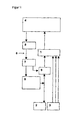
- the drawing shows a circuit diagram of the device according to the invention.
- inventive device comprises a buffer amplifier (1) to which at least one electrode (2) and sensors (3) are connected for the detection of physiological measurement signals.
- the isolation amplifier is further connected to a unit (4) for signal processing and control, which is connected to an optical transmitter for the stimulation (5).
- the optical transmitter (5) is connected via optical waveguides (6) to an optical receiver (7) which is connected to a stimulator unit (8) for signal generation.
- the signal generation stimulator unit (8) is in communication with the electrode (2).
- a relay (9) or a transistor At the entrance of the electrode (2) in the isolation amplifier (1) is a relay (9) or a transistor.
- the stimulation takes place via the macro or microelectrodes (2), which also derive the neuronal activity.
- the device measures both the discharge in the target region and a physiological trait associated with neuronal activity in the target region.
- the signals which are received via the electrode (2) in the brain, directed to the isolation amplifier (1) and set with the signals of the sensors (3) in relation.
- sensors (3) for example, at least one component from the group of epicortical electrodes, EEG scalp electrodes, depth electrodes, brain electrodes, peripheral electrodes, z. B. for measuring muscle activity or heart rate, accelerometer or a thermistor for measuring the respiratory rate are used. It is also possible to use two or more similar electrode types.
- bi or multivariate data analysis z For example, by analyzing phase synchronization or coherence, it is possible to establish functionality between the neural activity in a target point of the brain having activity at another part of the body or at another part of the brain.
- the isolating amplifier (1) it is possible in the simplest case to receive a measuring signal from the brain via at least one electrode (2), at the end of which a potential difference can be measured and in accordance with the invention with at least one further measured signal registered via the sensors (3).
- no relay or transistor (9) is required for this simple embodiment according to the above-mentioned case design a).
- the electrode (2) is at least two wires, at the ends of which a potential difference can be measured or applied.
- electrode 2 can also consist of more than two individual wires, which can be used for the determination of a measurement signal or the stimulation in the brain.
- four wires can be accommodated in one conductor cable, wherein a potential difference can be applied or measured between different ends. In this way, the size of the examined or stimulated target area can be varied.
- the number of wires making up the electrode is limited to upper values only by the associated thickness of the cable to be inserted into the brain, so that as little brain material as possible is to be damaged.
- Commercially available electrodes comprise four wires, but may also include five, six or more wires, but also only three wires.
- the electrode (2) comprises more than two wires
- at least two of these wires can also function as sensor (3), so that in this special case there is an embodiment in which the electrode (2) and the sensor (3 ) are united in a single component.
- structurally combined sensors (3) can not be present with electrode (2).
- the measuring signals of the electrode (2) and of the sensors (3) recorded by the isolating amplifier (1) are forwarded to the unit (4) for signal processing and control.
- c) is alternated between the procedure a) and b).
- the device provided for this procedure, in addition to the electrode (2), the isolation amplifier (1), and the sensors (3), a control device (4) for signal processing and control, which to the galvanically decoupled transmitter (5) with the stimulator unit (8 ) is connected to the signal generation.
- the isolating amplifier (1) is again preceded by a relay or a transistor (9).
- the device comprises means for selectively or preprogrammed connection of the stimulator unit (8).
- the unit for signal processing and control (4) comprises means for univariate and bivariate data processing for characterizing the frequency characteristics and the interaction (eg coherence, phase synchronization and directionality), as described, for example, in US Pat. Detection of n: m Phase Locking from noisysy Data: Application to Magnetoencephalography "by P. Tass, et al in Physical Review Letters, 81, 3291 (1998 ) is described.
- the device according to the invention may contain a reference database which is suitable for identifying regions of the brain via the registered stimulus response and / or the spontaneously registered neuronal discharge patterns.
- the reference database can be integrated, for example, in the controller (4).
- the signal processing and control can also be done in different devices 4, 4a (4a not shown in the figure).
- the processed data are passed on to the optical transmitter for the stimulation (5), which controls the optical receiver via the light guide (6).
- a galvanic decoupling of the stimulation control of the electrode (2) is effected.
- the relay circuit (1) is driven, which also prevents the interference of interference signals.
- the galvanic decoupling does not necessarily have to be done by an optical coupling of the control signals, but also other alternative controls can be used. These can be, for example, acoustic couplings, for example in the ultrasonic range, which do not disturb the examination. A trouble-free control can also be realized, for example, with the aid of suitable analog or digital filters.
- the relay circuit or transistor ensures that the neural activity can be measured again immediately after each stimulus without the isolation amplifier overdriving.
- optical Receiver (7) is for example a photocell into consideration.
- the optical receiver forwards the signals input via the stimulation optical transmitter (5) to the stimulator unit (8) and the relay (1).
- Targeted stimuli are then transmitted via the stimulator unit (8) via the electrode (2) to the potential target region in the brain.
- the electrical impulses which have entered the target region through the stimulator unit (8) trigger a reaction in the brain, which in turn is relayed by the electrode (2) via the relay to the isolating amplifier (1), which transmits these brain signals with physiological features which coincide with the Sensors (3) are measured, compares.
- a direct functionality can be established between the relevance of the targeted brain region and the associated physiological responses.
- the device according to the invention can be used in medicine, in particular in neurology and psychiatry.
Landscapes
- Health & Medical Sciences (AREA)
- Life Sciences & Earth Sciences (AREA)
- Animal Behavior & Ethology (AREA)
- Biophysics (AREA)
- Veterinary Medicine (AREA)
- Engineering & Computer Science (AREA)
- Biomedical Technology (AREA)
- Heart & Thoracic Surgery (AREA)
- Public Health (AREA)
- General Health & Medical Sciences (AREA)
- Surgery (AREA)
- Physics & Mathematics (AREA)
- Molecular Biology (AREA)
- Medical Informatics (AREA)
- Pathology (AREA)
- Nuclear Medicine, Radiotherapy & Molecular Imaging (AREA)
- Radiology & Medical Imaging (AREA)
- Neurology (AREA)
- Neurosurgery (AREA)
- Measurement And Recording Of Electrical Phenomena And Electrical Characteristics Of The Living Body (AREA)
- Electrotherapy Devices (AREA)
- Control Of Indicators Other Than Cathode Ray Tubes (AREA)
- Magnetic Resonance Imaging Apparatus (AREA)
Abstract
Description
Die Erfindung betrifft eine Vorrichtung zur Lokalisation des Zielpunktes von Elektroden zur Hirnstimulation, insbesondere zur Tiefenhirnstimulation.The invention relates to a device for localizing the target point of electrodes for brain stimulation, in particular for deep brain stimulation.
Symptome von neurologischen Erkrankungen, wie z. B. Akinese, Rigor und Tremor werden durch Fehlfunktionen räumlich umschriebener Gebiete des Gehirns hervorgerufen. Diese Symptome können durch Hirnstimulation gelindert oder beseitigt werden, beispielsweise durch Tiefenhirnstimulation. Entscheidend für den Stimulationserfolg ist neben den Stimulationsparametern der Ort der Stimulation.
Die Hirnareale werden nach dem Stand der Technik beispielsweise durch NMR-Aufnahmen oder Computertomographieaufnahmen im groben lokalisiert. Die Genauigkeit dieses Verfahrens ist durch die natürliche Variabilität des anatomischen Aufbaus des Gehirns und durch die begrenzte Auflösung der Verfahren auf Grund der physikalischen Rahmenbedingungen beschränkt. Insbesondere können die für die Fehlfunktion verantwortlichen Neuronenpopulationen klein sein, im Vergleich zu den in den NMR- oder CT-Aufnahmen lokalisierten Regionen. Es ist daher weiterhin notwendig, aufbauend auf den mit diesen Methoden gewonnenen Informationen, eine genauere Bestimmung der Zielpunkte vorzunehmen.Symptoms of neurological diseases, such. As akinesia, rigor and tremor are caused by malfunction of spatially circumscribed areas of the brain. These symptoms can be alleviated or eliminated by brain stimulation, such as deep brain stimulation. Decisive for the stimulation success is in addition to the stimulation parameters of the place of stimulation.
The brain areas are roughly localized according to the prior art, for example by NMR images or computed tomography images. The accuracy of this method is limited by the natural variability of the anatomical structure of the brain and by the limited resolution of the methods due to the physical constraints. In particular, the neuron populations responsible for the malfunction can be small compared to the regions located in the NMR or CT images. It is therefore still necessary, based on the information obtained with these methods, to make a more precise determination of the target points.
Nach einer bekannten Methode, wie sie beispielsweise in dem Artikel von
Bei einer anderen Methode, die aus der Veröffentlichung von
Die Schrift
Die nach dem Stand der Technik bekannten Verfahren sind sehr zeit- und personalintensiv und es fallen keine objektivierbaren Daten an. Es wird lediglich der amplitutenbedingte Stimuluserfolg analysiert. Zusätzlich werden durch das Einbringen der Elektroden kleinste Hirnbereiche verletzt, was dazu führt, dass die Reaktionen auf die Reizungen und die spontane Aktivität in diesen Hirnarealen für einen gewissen Zeitraum geändert werden, bis die entsprechenden Stellen verheilt sind.The methods known from the prior art are very time-consuming and labor-intensive and there are no objectifiable data. Only the stimulus-related stimulus success is analyzed. In addition, inserting the electrodes injures the smallest areas of the brain, which causes the responses to the irritation and spontaneous activity in these areas of the brain to be changed over a period of time until the corresponding sites heal.
Es ist daher die Aufgabe der Erfindung eine Vorrichtung zu schaffen, mit der die optimalen Zielpunkte im Gehirn schnell und besonders objektiv bestimmt werden können. Das Auffinden dieser Zielpunkte soll erleichtert werden.It is therefore an object of the invention to provide a device with which the optimal target points in the brain can be determined quickly and particularly objectively. The finding of these target points should be facilitated.
Ausgehend vom Oberbegriff des Anspruchs 1 wird die Aufgabe erfindungsgemäß gelöst, mit den im kennzeichnenden Teil des Anspruchs 1 angegebenen Merkmalen.Starting from the preamble of
Mit der erfindungsgemäßen Vorrichtung ist es nunmehr möglich, auf schnelle Art und Weise eine objektive Bestimmung des optimalen Zielpunktes im Gehirn vorzunehmen. Die Vorrichtung ermöglicht insbesondere, einen Zusammenhang zwischen dem Zielort im Gehirn und der Dysfunktion herzustellen.With the device according to the invention, it is now possible to carry out an objective determination of the optimal target point in the brain in a rapid manner. In particular, the device makes it possible to establish a connection between the destination in the brain and the dysfunction.
Vorteilhafte Weiterbildungen der Erfindung sind in den Unteransprüchen angegeben.Advantageous developments of the invention are specified in the subclaims.
In der Zeichnung ist ein Schaltschema der erfindungsgemäßen Vorrichtung angegeben.The drawing shows a circuit diagram of the device according to the invention.
Es zeigt:
- Figur 1.:
- Eine bevorzugte Ausgestaltung der erfindungsgemäßen Vorrichtung als Blockschema.
- Figure 1 .:
- A preferred embodiment of the device according to the invention as a block diagram.
Die in
Die erfindungsgemäße Vorrichtung kann grundsätzlich auf drei verschiedene Arbeitsweisen betrieben werden:
- Die Elektrode (2) misst die neurologische Aktivität, z. B. das lokale Feldpotential (LFP),wobei
- a) ohne oder
- b) mit Stimulation der Zielregion oder
- c) alternierend mit und ohne Stimulation der Zielregion gearbeitet wird.
- Die Sensoren (3) messen ein elektrophysiologisches Merkmal, welches mit der über die Elektrode (2) abgeleiteten neuronalen Aktivität in funktionellem Zusammenhang steht, wie z. B. die neuronale Aktivität einer anderen Hirnregion, den peripheren Tremor oder Herzfrequenz, Atemfrequenz, Durchblutung, Blutdruck, Blutgase.
- The electrode (2) measures the neurological activity, e.g. B. the local field potential (LFP), where
- a) without or
- b) with stimulation of the target region or
- c) working alternately with and without stimulation of the target region.
- The sensors (3) measure an electrophysiological feature which is functionally related to the neuronal activity derived via the electrode (2) stands, such as Neuronal activity of another brain region, peripheral tremor or heart rate, respiratory rate, blood flow, blood pressure, blood gases.
Im Falle b) erfolgt die Stimulation über die Makro- oder Mikroelektroden (2), welche auch die neuronale Aktivität ableiten.In case b), the stimulation takes place via the macro or microelectrodes (2), which also derive the neuronal activity.
Erfindungsgemäß wird mit der Vorrichtung sowohl die Entladung in der Zielregion als auch ein physiologisches Merkmal, welches mit der neuronalen Aktivität in der Zielregion in Verbindung steht, gemessen. Hierzu werden die Signale, welche über die Elektrode (2) im Gehirn aufgenommen werden, an den Trennverstärker (1) geleitet und mit den Signalen der Sensoren (3) in Bezug gesetzt.According to the invention, the device measures both the discharge in the target region and a physiological trait associated with neuronal activity in the target region. For this purpose, the signals, which are received via the electrode (2) in the brain, directed to the isolation amplifier (1) and set with the signals of the sensors (3) in relation.
Als Sensoren (3) können beispielsweise mindestens eine Komponente aus der Gruppe epikkortikale Elektroden, EEG-Skalp-Elektroden, Tiefenelektroden, Hirnelektroden, periphere Elektroden, z. B. zum Messen von Muskelaktivität oder Herzfrequenz, Akzelerometer oder ein Thermistor zur Messung der Atemfrequenz eingesetzt werden. Es können auch zwei oder mehrere gleichartige Elektrodentypen eingesetzt werden.As sensors (3), for example, at least one component from the group of epicortical electrodes, EEG scalp electrodes, depth electrodes, brain electrodes, peripheral electrodes, z. B. for measuring muscle activity or heart rate, accelerometer or a thermistor for measuring the respiratory rate are used. It is also possible to use two or more similar electrode types.
Erfindungsgemäß ist es hiermit möglich, durch bi- bzw. multivariate Datenanalyse z. B. durch Analyse der Phasensynchronisation oder Kohärenz eine Funktionalität zwischen der neuronalen Aktivität in einem Zielpunkt des Gehirns mit einer Aktivität an einem anderen Körperteil oder an einer anderen Stelle des Gehirns festzustellen. Mit dem Trennverstärker (1) ist es im einfachsten Fall möglich, über wenigstens eine Elektrode (2), an deren Ende eine Potentialdifferenz gemessen werden kann, ein Messsignal aus dem Gehirn zu empfangen und erfindungsgemäß mit mindestens einem weiteren über die Sensoren (3) registrierten Messsignal in Bezug zu setzen. Für diese einfache Ausführungsform gemäß der oben angeführten Fallgestaltung a) wird kein Relais oder kein Transistor (9) benötigt.According to the invention, it is hereby possible by bi or multivariate data analysis z. For example, by analyzing phase synchronization or coherence, it is possible to establish functionality between the neural activity in a target point of the brain having activity at another part of the body or at another part of the brain. With the isolating amplifier (1) it is possible in the simplest case to receive a measuring signal from the brain via at least one electrode (2), at the end of which a potential difference can be measured and in accordance with the invention with at least one further measured signal registered via the sensors (3). For this simple embodiment according to the above-mentioned case design a), no relay or transistor (9) is required.
Bei der Elektrode (2) handelt es sich um mindestens zwei Drähte, an deren Enden eine Potentialdifferenz gemessen oder angelegt werden kann. In einer weiteren Ausführungsform kann Elektrode 2 auch aus mehr als zwei einzelnen Drähten bestehen, die für die Ermittlung eines Messsignals bzw. die Stimulation im Gehirn herangezogen werden können. Beispielsweise können vier Drähte in einem Leiterkabel untergebracht sein, wobei zwischen verschiedenen Enden eine Potentialdifferenz angelegt oder gemessen werden kann. Hierdurch lässt sich die Größe des untersuchten bzw. stimulierten Zielgebietes variieren. Die Anzahl der Drähte, aus welchen sich die Elektrode zusammensetzt, ist nach oberen Werten hin lediglich durch die damit verbundene Dicke des in das Gehirn einzuführenden Kabels begrenzt, so dass möglichst wenig Hirnmaterial beschädigt werden soll. Handelsübliche Elektroden umfassen vier Drähte, es können jedoch auch fünf, sechs oder mehr Drähte, aber auch nur drei Drähte umfasst sein.The electrode (2) is at least two wires, at the ends of which a potential difference can be measured or applied. In a further embodiment,
Für den Fall, dass die Elektrode (2) mehr als zwei Drähte umfasst, können mindestens zwei dieser Drähte auch als Sensor (3) fungieren, so dass in diesem Spezialfall eine Ausführungsform vorliegt, bei der die Elektrode (2) und der Sensor (3) in einem einzigen Bauteil vereint sind. Neben diesem Bauteil können zusätzlich nicht mit Elektrode (2) baulich vereinte Sensoren (3) vorhanden sein.In the event that the electrode (2) comprises more than two wires, at least two of these wires can also function as sensor (3), so that in this special case there is an embodiment in which the electrode (2) and the sensor (3 ) are united in a single component. In addition to this component additionally structurally combined sensors (3) can not be present with electrode (2).
In einer bevorzugten Ausführungsform der Erfindung werden nicht nur lediglich spontane Hirnsignale - also Signale ohne vorhergehende Stimulation gemäß der Fallgestaltung a)- sondern auch Signale verwertet, welche durch eine Stimulation über die Elektroden hervorgerufen worden sind, wie in der Fallgestaltung b). Hierzu werden die vom Trennverstärker (1) aufgenommenen Messsignale der Elektrode (2) sowie der Sensoren (3) an die Einheit (4) zur,Signalverarbeitung und Steuerung weitergegeben.In a preferred embodiment of the invention not only only spontaneous brain signals - ie signals without prior stimulation according to the case design a) - but also signals are utilized, which have been caused by stimulation via the electrodes, as in the case design b). For this purpose, the measuring signals of the electrode (2) and of the sensors (3) recorded by the isolating amplifier (1) are forwarded to the unit (4) for signal processing and control.
In einer weiteren bevorzugten Ausführungsform c) wird zwischen den Verfahrensweise a) und b) alterniert. Die für diese Verfahrensweise vorgesehene Vorrichtung umfaßt neben der Elektrode (2), dem Trennverstärker (1), sowie den Sensoren (3) ein Steuerungsgerät (4) zur Signalverarbeitung und Steuerung, welche an den galvanisch entkoppelten Sender (5) mit der Stimulatoreinheit (8) zur Signalerzeugung in Verbindung steht. Bei dieser Ausführungsform ist dem Trennverstärker (1) wiederum ein Relais oder ein Transistor (9) vorgeschaltet. Bei dieser Ausführungsform umfasst die Vorrichtung Mittel zum wahlweisen oder vorprogrammierten Zuschalten der Stimulatoreinheit (8).In a further preferred embodiment c) is alternated between the procedure a) and b). The device provided for this procedure, in addition to the electrode (2), the isolation amplifier (1), and the sensors (3), a control device (4) for signal processing and control, which to the galvanically decoupled transmitter (5) with the stimulator unit (8 ) is connected to the signal generation. In this embodiment, the isolating amplifier (1) is again preceded by a relay or a transistor (9). In this embodiment, the device comprises means for selectively or preprogrammed connection of the stimulator unit (8).
Die Einheit zur Signalverarbeitung und Steuerung (4) umfasst Mittel für eine univariate und bivariate Datenverarbeitung zur Kennzeichnung der Frequenzeigenschaften und der Interaktion (Z. B. Kohärenz, Phasensynchronisation und Direktionalität), wie sie beispielsweise in "
Weiterhin umfasst sie vorzugsweise Mittel zur Visualisierung der Signale und weiterhin vorzugsweise eine Datensicherung. Weiterhin kann die erfindungsgemäße Vorrichtung eine Referenzdatenbank enthalten, welche geeignet ist, Hirnregionen über die registrierte Reizantwort und/oder die spontan registrierten neuronalen Entladungsmuster zu identifizieren. Die Referenzdatenbank kann beispielsweise in die Steuerung (4) integriert sein. Die Signalverarbeitung und Steuerung können auch in verschiedenen Geräten 4, 4a (4a in der Fig. nicht dargestellt) erfolgen. Die verarbeiteten Daten werden an den optischen Sender für die Stimulation (5) weitergegeben, welcher über den Lichtleiter (6) den optischen Empfänger ansteuert. Durch das optische Einkoppeln von Steuersignalen in den optischen Empfänger bei den Verfahrensweise b) und c), wird eine galvanische Entkopplung der Stimulationssteuerung von der Elektrode (2) bewirkt. Dies bedeutet, dass eine Einstreuung von Störsignalen von der Einheit zur Signalverarbeitung und Steuerung (4) in die Elektrode (2) verhindert wird. Weiterhin wird ausgehend vom optischen Sender für die Stimulation (5) über den optischen Empfänger (7) die Relaisschaltung (1) angesteuert, was ebenfalls die Einstreuung von Störsignalen verhindert. Die galvanische Entkopplung muss dabei nicht zwingend durch eine optische Einkopplung der Steuersignale erfolgen, vielmehr können auch andere alternative Steuerungen verwendet werden. Diese können beispielsweise akustische Einkopplungen zum Beispiel im Ultraschallbereich sein, die die Untersuchung nicht stören. Eine störungsfreie Steuerung kann auch beispielsweise unter Zuhilfenahme geeigneter analoger oder digitaler Filter realisiert werden.
Die Relaisschaltung oder der Transistor stellt sicher, dass die neuronale Aktivität unmittelbar nach jedem Stimulus wieder gemessen werden kann ohne dass der Trennverstärker übersteuert. Als optischer Empfänger (7) kommt beispielsweise eine Photozelle in Betracht. Der optische Empfänger gibt die über den optischen Sender für die Stimulation (5) eingegebenen Signale an die Stimulatoreinheit (8) und das Relais (1) weiter. Über die Stimulatoreinheit (8) werden dann gezielte Stimuli über die Elektrode (2) an die potenzielle Zielregion im Gehirn weitergegeben. Die durch die Stimulatoreinheit (8) in die Zielregion gelangten elektrischen Impulse lösen im Gehirn eine Reaktion aus, welche durch die Elektrode (2) wiederum über das Relais an den Trennverstärker (1) weitergegeben werden, der diese Hirnsignale mit physiologischen Merkmalen, welche mit den Sensoren (3) gemessen werden, vergleicht. Somit kann eine direkte Funktionalität zwischen der Relevanz der angepeilten Hirnregion und den damit verbundenen physiologischen Reaktionen hergestellt werden.Furthermore, it preferably comprises means for visualizing the signals and furthermore preferably a data backup. Furthermore, the device according to the invention may contain a reference database which is suitable for identifying regions of the brain via the registered stimulus response and / or the spontaneously registered neuronal discharge patterns. The reference database can be integrated, for example, in the controller (4). The signal processing and control can also be done in
The relay circuit or transistor ensures that the neural activity can be measured again immediately after each stimulus without the isolation amplifier overdriving. As optical Receiver (7) is for example a photocell into consideration. The optical receiver forwards the signals input via the stimulation optical transmitter (5) to the stimulator unit (8) and the relay (1). Targeted stimuli are then transmitted via the stimulator unit (8) via the electrode (2) to the potential target region in the brain. The electrical impulses which have entered the target region through the stimulator unit (8) trigger a reaction in the brain, which in turn is relayed by the electrode (2) via the relay to the isolating amplifier (1), which transmits these brain signals with physiological features which coincide with the Sensors (3) are measured, compares. Thus, a direct functionality can be established between the relevance of the targeted brain region and the associated physiological responses.
Beim Gebrauch der erfindungsgemäßen Vorrichtung werden vorzugsweise folgende Fragestellungen überprüft.
- 1. Liegt eine pathologische rhythmische Aktivität am Zielort vor? Falls ja, wird die funktionelle Bedeutung dieser rhythmischen Aktivität in folgender Weise untersucht:
- 2. Ist diese Aktivität phasensynchron oder kohärent mit der Muskelaktivität oder der Aktivität in einem anderen Hirnareal (Messung über eine weitere Tiefenelektrode oder über eine epikortikale Elektrode oder eine EEG-Skalp-Elektrode).
- 3. Welches ist die Direktionalität der Interaktion zwischen den beiden Messsignalen? Treibt das LFP (lokales Feldpotential) von der Tiefenelektrode die periphere Muskelaktivität oder umgekehrt? Hierdurch wird entschieden, ob es sich beim Tiefenareal um einen Generator des peripheren Tremors handelt, oder ob im Zielareal ein propriozeptives Feedback, das heißt Rückmeldungen vom Funktionszustand z. B. der Muskeln und Sehnen, detektiert wird.
- 4. Neben der Untersuchung der "spontan", das heißt ohne Stimulation, gewonnenen Signale wird zusätzlich noch die Reaktion der Messsignale (z. B. des Zielareals und der Muskelaktivität) auf standardisierte Testreize objektiv untersucht und klassifiziert. Hierbei wird getestet, wie einerseits die Zielregion und andererseits die Interaktion zwischen Zielregion und einer anderen Hirnregion oder zwischen Zielregion und peripherer Muskelaktivität durch ein standardisiertes Inventar an Stimuli (z. B. kurze Hochfrequenzreize (>100 Hz), periodische Pulse mit einer Pulsfrequenz im Bereich der Tremorfrequenz) moduliert werden. Zur Klassifikation bzw. funktionellen Identifikation des Zielareals werden die Ergebnisse vorzugsweise mit einer Referenz-Datenbank online verglichen.
- 1. Is there a pathological rhythmic activity at the destination? If so, the functional significance of this rhythmic activity is investigated in the following way:
- 2. Is this activity phase synchronous or coherent with muscle activity or activity in another brain area (measurement via another depth electrode or via an epicortical electrode or an EEG scalp electrode).
- 3. What is the directionality of the interaction between the two measurement signals? The LFP (local field potential) drives the peripheral electrode from the peripheral Muscle activity or vice versa? This determines whether the depth area is a generator of the peripheral tremor, or whether in the target area a proprioceptive feedback, ie feedback from the functional state z. As the muscles and tendons, is detected.
- 4. In addition to the examination of the signals obtained "spontaneously", ie without stimulation, the reaction of the measurement signals (eg of the target area and the muscle activity) to objective test stimuli is also objectively examined and classified. It tests how, on the one hand, the target region and, on the other hand, the interaction between the target region and another brain region or between the target region and peripheral muscle activity through a standardized inventory of stimuli (eg short high frequency stimuli (> 100 Hz), periodic pulses with a pulse rate in the range the tremor frequency) are modulated. For the classification or functional identification of the target area, the results are preferably compared online with a reference database.
Die erfindungsgemäße Vorrichtung kann in der Medizin, insbesondere in der Neurologie und Psychiatrie verwendet werden.The device according to the invention can be used in medicine, in particular in neurology and psychiatry.
Claims (10)
- Device for locating a target point of electrodes for brain stimulation, comprising at least one electrode (2) having at least two wires, at the end of which a potential difference corresponding to a neural potential difference can be measured, and at least one sensor (3) for recording physiological features, wherein it comprises an evaluation unit (4) which is connected to an isolation amplifier (1) and which comprises univariate and bivariate data processing to identify the frequency characteristics and the interaction between brain signals and physiological features such as coherence and/or phase synchronisation and/or directionality.
- Device according to claim 1, characterised in that the sensor (3) is an EEG scalp electrode, an epicortical electrode, a depth electrode, a brain electrode, a peripheral electrode, a muscle electrode or a combination of at least two of these sensors (3).
- Device according to claim 1 or 2, characterised in that the evaluation unit (4) has data visualisation means.
- Device according to one of claims 1 to 3,
characterised in that the evaluation unit (4) is connected to a control unit (8) which makes it possible to generate stimuli via the electrodes (2). - Device according to one of claims 1 to 4, characterised in that the evaluation unit (4) is connected to means for the electrically isolated coupling (5) of stimuli via the electrodes (2).
- Device according to claim 5, characterised in that the means for electrical coupling (5) comprise an optical transmitter and an optical receiver, which transfer signals to the electrode (2).
- Device according to one of claims 1 to 6, characterised in that the evaluation unit (4) is connected to means which prevent an overloading of the isolation amplifier.
- Device according to claim 7, characterised in that the means for preventing the overloading of the isolation amplifier (1) are a relay or a transistor or an electronic filter (9).
- Device according to one of claims 1 to 8, characterised in that the electrode (2) and the sensor (3) are at least partially enclosed in a component.
- Device according to one of claims 1 to 9, characterised in that it comprises an evaluation unit (4) having a multivariate data processing capability.
Applications Claiming Priority (3)
| Application Number | Priority Date | Filing Date | Title |
|---|---|---|---|
| DE10211765A DE10211765B4 (en) | 2002-03-14 | 2002-03-14 | Device for localizing the target point of electrodes for brain stimulation, in particular for deep brain stimulation |
| DE10211765 | 2002-03-14 | ||
| PCT/DE2003/000498 WO2003077986A1 (en) | 2002-03-14 | 2003-02-19 | Device for locating the target spot of electrodes used for brain stimulation, particularly deep brain stimulation |
Publications (2)
| Publication Number | Publication Date |
|---|---|
| EP1483017A1 EP1483017A1 (en) | 2004-12-08 |
| EP1483017B1 true EP1483017B1 (en) | 2008-10-15 |
Family
ID=27815715
Family Applications (1)
| Application Number | Title | Priority Date | Filing Date |
|---|---|---|---|
| EP03709630A Expired - Lifetime EP1483017B1 (en) | 2002-03-14 | 2003-02-19 | Device for locating the target spot of electrodes used for brain stimulation, particularly deep brain stimulation |
Country Status (11)
| Country | Link |
|---|---|
| US (1) | US20050154424A1 (en) |
| EP (1) | EP1483017B1 (en) |
| JP (1) | JP2005528138A (en) |
| AT (1) | ATE411073T1 (en) |
| AU (1) | AU2003214007A1 (en) |
| BR (1) | BR0308102A (en) |
| CA (1) | CA2479054A1 (en) |
| DE (3) | DE10211765B4 (en) |
| IL (1) | IL164010A0 (en) |
| MX (1) | MXPA04008875A (en) |
| WO (1) | WO2003077986A1 (en) |
Families Citing this family (20)
| Publication number | Priority date | Publication date | Assignee | Title |
|---|---|---|---|---|
| DE10355652A1 (en) | 2003-11-28 | 2005-06-30 | Forschungszentrum Jülich GmbH | Method and apparatus for desynchronizing neuronal brain activity |
| US20050137646A1 (en) | 2003-12-22 | 2005-06-23 | Scimed Life Systems, Inc. | Method of intravascularly delivering stimulation leads into brain |
| DE102004025945A1 (en) | 2004-05-27 | 2005-12-29 | Forschungszentrum Jülich GmbH | Method and device for decoupling and / or desynchronizing neuronal brain activity |
| US7286879B2 (en) | 2004-07-16 | 2007-10-23 | Boston Scientific Scimed, Inc. | Method of stimulating fastigium nucleus to treat neurological disorders |
| DE102004060514A1 (en) * | 2004-12-16 | 2006-06-29 | Forschungszentrum Jülich GmbH | Method and apparatus for desynchronizing neuronal brain activity, control, and methods for treating neuronal and / or psychiatric disorders |
| DE102006017716A1 (en) * | 2006-04-15 | 2007-10-18 | Forschungszentrum Jülich GmbH | Apparatus for measuring biomedical data of a subject and method for stimulating the subject with real-time processed data |
| US8280514B2 (en) * | 2006-10-31 | 2012-10-02 | Advanced Neuromodulation Systems, Inc. | Identifying areas of the brain by examining the neuronal signals |
| CN101557856B (en) * | 2006-12-13 | 2013-11-06 | 沙皮恩斯脑部刺激控制有限公司 | First time right placement of a DBS lead |
| WO2009026382A1 (en) * | 2007-08-20 | 2009-02-26 | Kopell, Brian, H. | Systems and methods for treating neurological disorders by light stimulation |
| US8600696B2 (en) | 2007-09-28 | 2013-12-03 | Oliver Zafiris | Method and system for determining a reaction signal for a selected location in an information processing system following the effect of at least one input signal |
| DE102008020070A1 (en) | 2008-04-22 | 2009-10-29 | Biotronik Crm Patent Ag | neurostimulator |
| US8892207B2 (en) | 2011-04-20 | 2014-11-18 | Medtronic, Inc. | Electrical therapy for facilitating inter-area brain synchronization |
| WO2012145244A1 (en) | 2011-04-20 | 2012-10-26 | Medtronic, Inc. | Method and apparatus for assessing neural activation |
| CN103501855B (en) | 2011-04-20 | 2015-12-23 | 美敦力公司 | The parameter of electricity treatment is determined based on bioelectric resonance response |
| US9173609B2 (en) | 2011-04-20 | 2015-11-03 | Medtronic, Inc. | Brain condition monitoring based on co-activation of neural networks |
| US8812098B2 (en) | 2011-04-28 | 2014-08-19 | Medtronic, Inc. | Seizure probability metrics |
| US9878161B2 (en) | 2011-04-29 | 2018-01-30 | Medtronic, Inc. | Entrainment of bioelectrical brain signals |
| US8977335B2 (en) | 2012-03-29 | 2015-03-10 | Ad-Tech Medical Instrument Corp. | Intracranial sensing and monitoring device with macro and micro electrodes |
| US9498628B2 (en) | 2014-11-21 | 2016-11-22 | Medtronic, Inc. | Electrode selection for electrical stimulation therapy |
| EP3710103B1 (en) | 2017-11-17 | 2024-02-21 | Boston Scientific Neuromodulation Corporation | Systems for generating intermittent stimulation using electrical stimulation systems |
Family Cites Families (10)
| Publication number | Priority date | Publication date | Assignee | Title |
|---|---|---|---|---|
| WO1995035060A1 (en) * | 1994-06-20 | 1995-12-28 | Auckland Uniservices Limited | Brain damage monitor |
| US6066163A (en) * | 1996-02-02 | 2000-05-23 | John; Michael Sasha | Adaptive brain stimulation method and system |
| AU714617B2 (en) * | 1996-04-04 | 2000-01-06 | Medtronic, Inc. | Living tissue stimulation and recording techniques |
| US6094598A (en) * | 1996-04-25 | 2000-07-25 | Medtronics, Inc. | Method of treating movement disorders by brain stimulation and drug infusion |
| US6493576B1 (en) * | 1996-06-17 | 2002-12-10 | Erich Jaeger Gmbh | Method and apparatus for measuring stimulus-evoked potentials of the brain |
| US6052619A (en) * | 1997-08-07 | 2000-04-18 | New York University | Brain function scan system |
| AU9687598A (en) * | 1997-10-06 | 1999-04-27 | Somnus Medical Technologies, Inc. | Electro-surgical instrument with a graphical user interface |
| US5938688A (en) * | 1997-10-22 | 1999-08-17 | Cornell Research Foundation, Inc. | Deep brain stimulation method |
| US6027456A (en) * | 1998-07-10 | 2000-02-22 | Advanced Neuromodulation Systems, Inc. | Apparatus and method for positioning spinal cord stimulation leads |
| DE10044115A1 (en) * | 1999-09-13 | 2001-04-12 | Medtronic Inc | Combined micro-macro-brain stimulation lead and method of use |
-
2002
- 2002-03-14 DE DE10211765A patent/DE10211765B4/en not_active Expired - Fee Related
-
2003
- 2003-02-19 JP JP2003576037A patent/JP2005528138A/en active Pending
- 2003-02-19 AU AU2003214007A patent/AU2003214007A1/en not_active Abandoned
- 2003-02-19 CA CA002479054A patent/CA2479054A1/en not_active Abandoned
- 2003-02-19 IL IL16401003A patent/IL164010A0/en unknown
- 2003-02-19 MX MXPA04008875A patent/MXPA04008875A/en unknown
- 2003-02-19 BR BR0308102-8A patent/BR0308102A/en not_active IP Right Cessation
- 2003-02-19 WO PCT/DE2003/000498 patent/WO2003077986A1/en active Application Filing
- 2003-02-19 EP EP03709630A patent/EP1483017B1/en not_active Expired - Lifetime
- 2003-02-19 DE DE10390983T patent/DE10390983D2/en not_active Withdrawn - After Issue
- 2003-02-19 DE DE50310645T patent/DE50310645D1/en not_active Expired - Lifetime
- 2003-02-19 AT AT03709630T patent/ATE411073T1/en not_active IP Right Cessation
- 2003-02-19 US US10/507,957 patent/US20050154424A1/en not_active Abandoned
Also Published As
| Publication number | Publication date |
|---|---|
| DE10211765B4 (en) | 2004-06-03 |
| IL164010A0 (en) | 2005-12-18 |
| BR0308102A (en) | 2005-01-04 |
| DE10211765A1 (en) | 2003-10-09 |
| US20050154424A1 (en) | 2005-07-14 |
| EP1483017A1 (en) | 2004-12-08 |
| ATE411073T1 (en) | 2008-10-15 |
| AU2003214007A1 (en) | 2003-09-29 |
| MXPA04008875A (en) | 2004-11-26 |
| DE10390983D2 (en) | 2005-02-10 |
| CA2479054A1 (en) | 2003-09-25 |
| JP2005528138A (en) | 2005-09-22 |
| WO2003077986A1 (en) | 2003-09-25 |
| DE50310645D1 (en) | 2008-11-27 |
Similar Documents
| Publication | Publication Date | Title |
|---|---|---|
| EP1483017B1 (en) | Device for locating the target spot of electrodes used for brain stimulation, particularly deep brain stimulation | |
| DE69736811T2 (en) | METHOD AND DEVICE FOR LOCATING CORTICAL LINKS | |
| EP0538739B1 (en) | Method and device for determining the state of health of a living being | |
| EP2887861B1 (en) | Apparatus for examining a phase distribution to identify a pathological interaction between different areas of the brain | |
| EP0355506B1 (en) | Arrangement for measuring local bioelectric currents in biological tissue | |
| EP2704629B1 (en) | Method for consciousness and pain monitoring, module for analyzing eeg signals and eeg narcosis monitor | |
| DE102019203627A1 (en) | Detection of disturbances in the measurement of bioelectrical signals | |
| DE602004005438T2 (en) | METHOD FOR MONITORING THE NERVOUS SYSTEM | |
| Martinez-Valdes et al. | Consensus for experimental design in electromyography (CEDE) project: Single motor unit matrix | |
| DE102008021940A1 (en) | Stimulation arrangement for measuring the physiological signal reactivity | |
| EP2799110A1 (en) | Method for operating a bioresonance device | |
| EP4076194B1 (en) | A process and a device for decomposition of compound muscle action potentials | |
| CN113545792A (en) | TMS-EEG-based neural biomarker detection method | |
| DE10353969B4 (en) | Bio-signal measurement system | |
| DE69724261T2 (en) | ELECTRO-MEDICAL DEVICE | |
| EP3426143B1 (en) | Apparatus for electrostimulation of a test subject | |
| EP3838132A1 (en) | Suppression of echo effects on electrodes in the measurement of bioelectrical signals | |
| DE102011114045B4 (en) | Method, arrangement and computer program for detecting derivations of event-related potentials of neural activity | |
| DE102004020515A1 (en) | Wireless recording, remote monitoring of animal muscle activities involves using measurement device miniaturized/ergonomically designed so investigated animal is almost unaffected in perception, movement processes and natural environment | |
| WO2013144229A1 (en) | Device and method for measuring electrical potentials of a living thing | |
| Martinez-Valdes et al. | VU Research Portal | |
| DE2917704C2 (en) | ||
| Kaarna | EEG analysis of Parkinson's disease patients treated with 50 Hz repetitive transcranial magnetic stimulation | |
| DE4410691A1 (en) | Analysis and documentation appts for skin physiological changes | |
| DE4030001A1 (en) | Vacuum-operated tester of optic nerve pressure tolerance - simulates intra=ocular pressure increase of up to 130 torr during measurement and display of visually evoked potential |
Legal Events
| Date | Code | Title | Description |
|---|---|---|---|
| PUAI | Public reference made under article 153(3) epc to a published international application that has entered the european phase |
Free format text: ORIGINAL CODE: 0009012 |
|
| 17P | Request for examination filed |
Effective date: 20040811 |
|
| AK | Designated contracting states |
Kind code of ref document: A1 Designated state(s): AT BE BG CH CY CZ DE DK EE ES FI FR GB GR HU IE IT LI LU MC NL PT SE SI SK TR |
|
| AX | Request for extension of the european patent |
Extension state: AL LT LV MK RO |
|
| 17Q | First examination report despatched |
Effective date: 20060928 |
|
| 17Q | First examination report despatched |
Effective date: 20060928 |
|
| GRAP | Despatch of communication of intention to grant a patent |
Free format text: ORIGINAL CODE: EPIDOSNIGR1 |
|
| GRAS | Grant fee paid |
Free format text: ORIGINAL CODE: EPIDOSNIGR3 |
|
| GRAA | (expected) grant |
Free format text: ORIGINAL CODE: 0009210 |
|
| RAP1 | Party data changed (applicant data changed or rights of an application transferred) |
Owner name: FORSCHUNGSZENTRUM JUELICH GMBH |
|
| AK | Designated contracting states |
Kind code of ref document: B1 Designated state(s): AT BE BG CH CY CZ DE DK EE ES FI FR GB GR HU IE IT LI LU MC NL PT SE SI SK TR |
|
| REG | Reference to a national code |
Ref country code: GB Ref legal event code: FG4D Free format text: NOT ENGLISH Ref country code: CH Ref legal event code: EP |
|
| REG | Reference to a national code |
Ref country code: IE Ref legal event code: FG4D Free format text: LANGUAGE OF EP DOCUMENT: GERMAN |
|
| REF | Corresponds to: |
Ref document number: 50310645 Country of ref document: DE Date of ref document: 20081127 Kind code of ref document: P |
|
| NLV1 | Nl: lapsed or annulled due to failure to fulfill the requirements of art. 29p and 29m of the patents act | ||
| PG25 | Lapsed in a contracting state [announced via postgrant information from national office to epo] |
Ref country code: BG Free format text: LAPSE BECAUSE OF FAILURE TO SUBMIT A TRANSLATION OF THE DESCRIPTION OR TO PAY THE FEE WITHIN THE PRESCRIBED TIME-LIMIT Effective date: 20090115 Ref country code: ES Free format text: LAPSE BECAUSE OF FAILURE TO SUBMIT A TRANSLATION OF THE DESCRIPTION OR TO PAY THE FEE WITHIN THE PRESCRIBED TIME-LIMIT Effective date: 20090126 |
|
| PG25 | Lapsed in a contracting state [announced via postgrant information from national office to epo] |
Ref country code: FI Free format text: LAPSE BECAUSE OF FAILURE TO SUBMIT A TRANSLATION OF THE DESCRIPTION OR TO PAY THE FEE WITHIN THE PRESCRIBED TIME-LIMIT Effective date: 20081015 Ref country code: SI Free format text: LAPSE BECAUSE OF FAILURE TO SUBMIT A TRANSLATION OF THE DESCRIPTION OR TO PAY THE FEE WITHIN THE PRESCRIBED TIME-LIMIT Effective date: 20081015 Ref country code: NL Free format text: LAPSE BECAUSE OF FAILURE TO SUBMIT A TRANSLATION OF THE DESCRIPTION OR TO PAY THE FEE WITHIN THE PRESCRIBED TIME-LIMIT Effective date: 20081015 Ref country code: PT Free format text: LAPSE BECAUSE OF FAILURE TO SUBMIT A TRANSLATION OF THE DESCRIPTION OR TO PAY THE FEE WITHIN THE PRESCRIBED TIME-LIMIT Effective date: 20090316 |
|
| REG | Reference to a national code |
Ref country code: IE Ref legal event code: FD4D |
|
| PG25 | Lapsed in a contracting state [announced via postgrant information from national office to epo] |
Ref country code: IE Free format text: LAPSE BECAUSE OF FAILURE TO SUBMIT A TRANSLATION OF THE DESCRIPTION OR TO PAY THE FEE WITHIN THE PRESCRIBED TIME-LIMIT Effective date: 20081015 Ref country code: DK Free format text: LAPSE BECAUSE OF FAILURE TO SUBMIT A TRANSLATION OF THE DESCRIPTION OR TO PAY THE FEE WITHIN THE PRESCRIBED TIME-LIMIT Effective date: 20081015 Ref country code: EE Free format text: LAPSE BECAUSE OF FAILURE TO SUBMIT A TRANSLATION OF THE DESCRIPTION OR TO PAY THE FEE WITHIN THE PRESCRIBED TIME-LIMIT Effective date: 20081015 |
|
| PLBE | No opposition filed within time limit |
Free format text: ORIGINAL CODE: 0009261 |
|
| STAA | Information on the status of an ep patent application or granted ep patent |
Free format text: STATUS: NO OPPOSITION FILED WITHIN TIME LIMIT |
|
| BERE | Be: lapsed |
Owner name: FORSCHUNGSZENTRUM JULICH G.M.B.H. Effective date: 20090228 |
|
| PG25 | Lapsed in a contracting state [announced via postgrant information from national office to epo] |
Ref country code: IT Free format text: LAPSE BECAUSE OF FAILURE TO SUBMIT A TRANSLATION OF THE DESCRIPTION OR TO PAY THE FEE WITHIN THE PRESCRIBED TIME-LIMIT Effective date: 20081015 Ref country code: SE Free format text: LAPSE BECAUSE OF FAILURE TO SUBMIT A TRANSLATION OF THE DESCRIPTION OR TO PAY THE FEE WITHIN THE PRESCRIBED TIME-LIMIT Effective date: 20090115 Ref country code: CZ Free format text: LAPSE BECAUSE OF FAILURE TO SUBMIT A TRANSLATION OF THE DESCRIPTION OR TO PAY THE FEE WITHIN THE PRESCRIBED TIME-LIMIT Effective date: 20081015 |
|
| 26N | No opposition filed |
Effective date: 20090716 |
|
| PG25 | Lapsed in a contracting state [announced via postgrant information from national office to epo] |
Ref country code: MC Free format text: LAPSE BECAUSE OF NON-PAYMENT OF DUE FEES Effective date: 20090228 Ref country code: SK Free format text: LAPSE BECAUSE OF FAILURE TO SUBMIT A TRANSLATION OF THE DESCRIPTION OR TO PAY THE FEE WITHIN THE PRESCRIBED TIME-LIMIT Effective date: 20081015 |
|
| REG | Reference to a national code |
Ref country code: CH Ref legal event code: PL |
|
| PG25 | Lapsed in a contracting state [announced via postgrant information from national office to epo] |
Ref country code: CH Free format text: LAPSE BECAUSE OF NON-PAYMENT OF DUE FEES Effective date: 20090228 Ref country code: LI Free format text: LAPSE BECAUSE OF NON-PAYMENT OF DUE FEES Effective date: 20090228 |
|
| PG25 | Lapsed in a contracting state [announced via postgrant information from national office to epo] |
Ref country code: BE Free format text: LAPSE BECAUSE OF NON-PAYMENT OF DUE FEES Effective date: 20090228 |
|
| PG25 | Lapsed in a contracting state [announced via postgrant information from national office to epo] |
Ref country code: AT Free format text: LAPSE BECAUSE OF NON-PAYMENT OF DUE FEES Effective date: 20090219 |
|
| PG25 | Lapsed in a contracting state [announced via postgrant information from national office to epo] |
Ref country code: GR Free format text: LAPSE BECAUSE OF FAILURE TO SUBMIT A TRANSLATION OF THE DESCRIPTION OR TO PAY THE FEE WITHIN THE PRESCRIBED TIME-LIMIT Effective date: 20090116 |
|
| PG25 | Lapsed in a contracting state [announced via postgrant information from national office to epo] |
Ref country code: LU Free format text: LAPSE BECAUSE OF NON-PAYMENT OF DUE FEES Effective date: 20090219 |
|
| PG25 | Lapsed in a contracting state [announced via postgrant information from national office to epo] |
Ref country code: HU Free format text: LAPSE BECAUSE OF FAILURE TO SUBMIT A TRANSLATION OF THE DESCRIPTION OR TO PAY THE FEE WITHIN THE PRESCRIBED TIME-LIMIT Effective date: 20090416 |
|
| PG25 | Lapsed in a contracting state [announced via postgrant information from national office to epo] |
Ref country code: TR Free format text: LAPSE BECAUSE OF FAILURE TO SUBMIT A TRANSLATION OF THE DESCRIPTION OR TO PAY THE FEE WITHIN THE PRESCRIBED TIME-LIMIT Effective date: 20081015 |
|
| PG25 | Lapsed in a contracting state [announced via postgrant information from national office to epo] |
Ref country code: CY Free format text: LAPSE BECAUSE OF FAILURE TO SUBMIT A TRANSLATION OF THE DESCRIPTION OR TO PAY THE FEE WITHIN THE PRESCRIBED TIME-LIMIT Effective date: 20081015 |
|
| REG | Reference to a national code |
Ref country code: DE Ref legal event code: R082 Ref document number: 50310645 Country of ref document: DE Representative=s name: MANITZ FINSTERWALD PATENTANWAELTE PARTMBB, DE Ref country code: DE Ref legal event code: R082 Ref document number: 50310645 Country of ref document: DE Representative=s name: MANITZ, FINSTERWALD & PARTNER GBR, DE Ref country code: DE Ref legal event code: R082 Ref document number: 50310645 Country of ref document: DE Representative=s name: ZACCO PATENTANWALTS- UND RECHTSANWALTSGESELLSC, DE |
|
| REG | Reference to a national code |
Ref country code: FR Ref legal event code: PLFP Year of fee payment: 14 |
|
| REG | Reference to a national code |
Ref country code: FR Ref legal event code: PLFP Year of fee payment: 15 |
|
| REG | Reference to a national code |
Ref country code: FR Ref legal event code: PLFP Year of fee payment: 16 |
|
| REG | Reference to a national code |
Ref country code: DE Ref legal event code: R082 Ref document number: 50310645 Country of ref document: DE Representative=s name: ZACCO PATENTANWALTS- UND RECHTSANWALTSGESELLSC, DE Ref country code: DE Ref legal event code: R082 Ref document number: 50310645 Country of ref document: DE Representative=s name: VOSSIUS & PARTNER PATENTANWAELTE RECHTSANWAELT, DE |
|
| REG | Reference to a national code |
Ref country code: DE Ref legal event code: R082 Ref document number: 50310645 Country of ref document: DE Representative=s name: VOSSIUS & PARTNER PATENTANWAELTE RECHTSANWAELT, DE |
|
| PGFP | Annual fee paid to national office [announced via postgrant information from national office to epo] |
Ref country code: DE Payment date: 20200204 Year of fee payment: 18 Ref country code: GB Payment date: 20200212 Year of fee payment: 18 |
|
| PGFP | Annual fee paid to national office [announced via postgrant information from national office to epo] |
Ref country code: FR Payment date: 20200113 Year of fee payment: 18 |
|
| REG | Reference to a national code |
Ref country code: DE Ref legal event code: R119 Ref document number: 50310645 Country of ref document: DE |
|
| GBPC | Gb: european patent ceased through non-payment of renewal fee |
Effective date: 20210219 |
|
| PG25 | Lapsed in a contracting state [announced via postgrant information from national office to epo] |
Ref country code: DE Free format text: LAPSE BECAUSE OF NON-PAYMENT OF DUE FEES Effective date: 20210901 Ref country code: FR Free format text: LAPSE BECAUSE OF NON-PAYMENT OF DUE FEES Effective date: 20210228 Ref country code: GB Free format text: LAPSE BECAUSE OF NON-PAYMENT OF DUE FEES Effective date: 20210219 |