EP1476313B1 - Printing device and method, in which a humidity promoter is applied prior to the ink-repellent or ink-receptive layer - Google Patents
Printing device and method, in which a humidity promoter is applied prior to the ink-repellent or ink-receptive layer Download PDFInfo
- Publication number
- EP1476313B1 EP1476313B1 EP03708101A EP03708101A EP1476313B1 EP 1476313 B1 EP1476313 B1 EP 1476313B1 EP 03708101 A EP03708101 A EP 03708101A EP 03708101 A EP03708101 A EP 03708101A EP 1476313 B1 EP1476313 B1 EP 1476313B1
- Authority
- EP
- European Patent Office
- Prior art keywords
- ink
- layer
- print carrier
- carrier
- Prior art date
- Legal status (The legal status is an assumption and is not a legal conclusion. Google has not performed a legal analysis and makes no representation as to the accuracy of the status listed.)
- Expired - Lifetime
Links
Images


Classifications
-
- B—PERFORMING OPERATIONS; TRANSPORTING
- B41—PRINTING; LINING MACHINES; TYPEWRITERS; STAMPS
- B41N—PRINTING PLATES OR FOILS; MATERIALS FOR SURFACES USED IN PRINTING MACHINES FOR PRINTING, INKING, DAMPING, OR THE LIKE; PREPARING SUCH SURFACES FOR USE AND CONSERVING THEM
- B41N3/00—Preparing for use and conserving printing surfaces
- B41N3/006—Cleaning, washing, rinsing or reclaiming of printing formes other than intaglio formes
-
- B—PERFORMING OPERATIONS; TRANSPORTING
- B41—PRINTING; LINING MACHINES; TYPEWRITERS; STAMPS
- B41C—PROCESSES FOR THE MANUFACTURE OR REPRODUCTION OF PRINTING SURFACES
- B41C1/00—Forme preparation
- B41C1/10—Forme preparation for lithographic printing; Master sheets for transferring a lithographic image to the forme
-
- B—PERFORMING OPERATIONS; TRANSPORTING
- B41—PRINTING; LINING MACHINES; TYPEWRITERS; STAMPS
- B41J—TYPEWRITERS; SELECTIVE PRINTING MECHANISMS, i.e. MECHANISMS PRINTING OTHERWISE THAN FROM A FORME; CORRECTION OF TYPOGRAPHICAL ERRORS
- B41J29/00—Details of, or accessories for, typewriters or selective printing mechanisms not otherwise provided for
- B41J29/17—Cleaning arrangements
Definitions
- the invention relates to a method according to the claims for producing a printed image on a carrier material, wherein on the surface of the print carrier ink-attracting and ink-repellent regions are generated according to the structure of the printed image to be printed, wherein the ink-repellent regions are provided with a layer of an ink-repellent medium in that ink is applied to the surface of the print substrate, which adheres to the ink-attracting areas and which is not accepted by the ink-repellent areas, and in which the color distributed on the surface is printed on the substrate.
- ink-attracting and ink-repellent areas are distributed on the printing plate.
- the printing plate can be used for a variety of transfer printing operations. For each print image, a new plate must be created with ink-attracting and ink-repellent areas.
- a method which is called a direct imaging method in which a printing original is created in the printing device on a multilayer, silicone-coated film by selective burning away of the silicone top layer.
- the silicone-free areas are the ink-attracting areas that accept printing ink during the printing process. Every new print requires a new foil.
- hydrophobic and hydrophilic areas are produced on the surface of the print carrier in accordance with the structure of the print image to be printed.
- a thin film of moisture is first applied to the print substrate using applicator rollers or spraying devices, which wets the hydrophilic area of the print substrate.
- the inking roller transfers ink to the surface of the print substrate, which wets only those areas not covered by the moisture film. After dyeing, the color is finally transferred to the carrier material.
- a hydrophobic layer is removed by partial burning away and exposing a hydrophilic layer.
- the hydrophilic layer can be wetted with an ink-repellent fountain solution.
- the hydrophobic areas are ink accepting and can absorb ink during the printing process.
- a new printing plate must be used.
- the wetting of the printing plate with the ink-repelling dampening solution is achieved by targeted roughening and structuring of the plate surface.
- the resulting increase in surface area and porosity produces microcapillaries and leads to an increase in the effective surface energy and thus to a good wetting or spreading of the dampening solution.
- wetting-promoting substances are added to the wetting agent during offset printing. These reduce the surface tension of the fountain solution, which also leads to improved wetting of the surface of the print carrier.
- a CTP method (C omputer- T o P RESS process), wherein patterning processes can be performed repeatedly on the same surface of the print carrier.
- the surface of a print substrate is coated with an ink-repellent or ink-receptive layer.
- ink-attracting regions and ink-repelling regions are produced according to the structure of the printed image to be printed.
- the ink-attracting areas are then colored with paint.
- the surface of the print substrate is cleaned and coated again with an ink-repellent or ink-receptive layer.
- the layer used is a fountain solution layer or an ice layer.
- a wetting-promoting substance in molecular layer thickness is applied to the surface of the print carrier before the application and structuring of the fountain solution layer. Accordingly, the function wetting and coating separated, whereby the dampening solution does not have to be loaded with wetting agents.
- the method according to the invention allows the use of a very smooth surface of the print carrier, whereby the subsequent process steps are simplified, in particular the cleaning before re-structuring in digital printing. In addition, the wear of the pressure surface is reduced.
- color repellent or ink-receptive layer occurs.
- This layer is adapted to the applied color.
- the fountain solution layer is color-repellent.
- this fountain solution layer is color-attracting.
- oily inks are used, so that a water-containing fountain solution layer is ink repellent.
- FIG. 1 is a schematic representation of a printing device shown, which is constructed similar to that in the US Patent No. 5,067,404 the same applicant is described.
- a print carrier 10 in the present case an endless belt, is guided through a pretreatment device 12 which comprises a scoop roller 14 and an applicator roller 16 contains.
- the scoop roller 14 immersed in a liquid contained in a container 13, which contains a wetting-promoting substance.
- On the surface of the print carrier 10 is applied over the applicator roll 16, this substance containing surfactant in a molecular layer thickness.
- the layer thickness is typically less than 0.1 ⁇ m.
- the surface of the print carrier 10 is then guided in the direction of arrow P1 to a dampening unit 18, which applies a ink-repelling or ink-attracting dampening solution, for example water, from a dampening solution reservoir 24 to the surface of the print substrate 10 via a scoop roller 20 and an applicator roller 22.
- dampening solutions other than water can also be used.
- the order of the fountain solution layer can also be done by other methods, for example by steaming or spraying.
- the pressure-active surface of the print carrier 10 is completely provided with this fountain solution layer.
- the fountain solution layer typically has a layer thickness of less than 1 ⁇ m.
- the generally ink-repellent fountain solution layer is then patterned by an imaging device 26.
- laser radiation 28 is used for this purpose.
- ink-attracting regions and ink-repelling regions are formed according to the structure of the printed image to be printed.
- the structured dampening solution layer reaches an inking unit 30, which transfers ink from a storage container 38 onto the surface of the print carrier 10 with the aid of the rollers 32, 34, 36.
- the oil-containing color deposits on areas without water-containing dampening solution.
- the ink can also be transferred to the surface of the print carrier 10 by spraying, knife coating or condensing.
- a transfer to a carrier material 40 Upon further transport of the print carrier 10, a transfer to a carrier material 40, generally a paper web.
- the carrier material 40 is passed between two rollers 42, 44.
- a blanket cylinder (not shown) and further intermediate cylinders can be connected between the roller 42 and the print carrier 10, which effects a color split, as is known per se from the field of offset printing methods.
- the surface of the print carrier 10 is cleaned in a cleaning station 46.
- the cleaning station 46 includes a brush 48 and a wiper lip 50, which are brought into contact with the surface of the print carrier 10.
- the cleaning can be assisted by using ultrasound, high pressure liquid and / or steam.
- the cleaning can also be done using cleaning fluids and / or solvents.
- a new application of the wetting-promoting substance e.g. a surfactant, and a fountain solution and re-structuring done.
- a new print image can be printed.
- the cleaning device 46, the device 12 and the device 26 are then switched inactive.
- the still present in color residues print image is then colored again by the inking unit 30 and reprinted. In this mode, therefore, a plurality of identical printed images can be printed.
- FIG. 2 schematically shows a cross section through the print carrier 10 before and after structuring using the laser beam 28.
- the wetting is promoted by the application of a wetting-promoting substance on the print carrier surface 10. This happens within the printing cycle before the order of the Farbabsto-. fading fountain solution. Due to its physical and chemical properties, the wetting-promoting substance can be applied to the surface as an extremely thin layer of a few molecule layers, preferably smaller than 0.1 .mu.m. This layer is sufficient to favor on its free surface, the wetting with the ink-repellent fountain solution, so that this can also be applied as a very thin layer 54, preferably less than 1 micron.
- the continuing printing process is not affected by the small amount of wetting-promoting substance, in this case a surfactant layer 52. It can be easily removed by the cleaning process integrated in the printing cycle.
- the wetting-promoting layer 52 can be dispensed with the otherwise roughened, porous printing plate surface. Instead, a smooth surface of the print carrier 10 is possible to clean with significantly less effort. A fast and stable cleaning process is indispensable for such a digital lithographic printing process or offset printing process and a decisive factor for its effectiveness. Accordingly, the surface of the print carrier 10 has a roughness which is smaller than the roughness used in the standard offset printing process. Typically, the mean roughness R z is less than 10 microns, preferably less than 5 microns. Expressed as the average roughness value R a , the roughness value lies in the range of less than 2 ⁇ m, preferably less than 1 ⁇ m.
- a change in the molecular or atomic structure of the material of the print carrier as well as a permanent and wetting-promoting firmly anchored to the surface of the print carrier Layer is not necessary.
- the additionally applied wetting-promoting substance proposed here for example the surfactant layer 52, develops its wetting-promoting action even at very low levels. Accordingly, its influence on the characteristics of the print substrate 10 is negligible in many respects.
- the dampening agent layer 54 and the surfactant layer 52 are removed by the laser beam 28 in accordance with the required image structure. These areas are then colored by the inking unit 30 with color. Due to the very smooth surface of the print carrier 10, the cleaning is facilitated, the surfactant layer 52 is completely removed again. Furthermore, the wear of the surface of the print carrier 10 is reduced.
- FIGS. 3, 4 and 5 show a further embodiment of the invention.
- FIG. 3 takes place in contrast to the embodiment according to FIG. 1 before applying the ink-repellent or ink-receptive layer on the usable surface of the print carrier structuring of a hydrophilic layer having a molecular layer thickness.
- a steam device 60 is used, which acts on the surface of the print carrier 10 with hot water vapor.
- the print carrier 10 is provided on its surface with a SiO 2 coating. After the steam treatment, the print carrier 10 is dried by a suction device 62.
- the hot water vapor generates a hydrophilic molecular structure on the outer surface, eg SiOH.
- hydrophilic regions and hydrophobic regions arise in accordance with the structure of the printed image to be printed.
- the downstream dampening unit 18 the entire usable surface of the print carrier 10 is brought into contact with a dampening agent layer, wherein the fountain solution only attaches to the hydrophilic areas, so that ink-attracting areas and ink-repellent areas arise in accordance with the structuring.
- a paint is applied by the inking unit 30, wherein the oil-containing color attaches to areas without aqueous dampening solution.
- the transfer printing of the printed image onto the carrier material 40 takes place.
- the hydrophilic layer is patterned on the surface of the print carrier 10 according to the printed image.
- the hydrophilic layer is extremely thin and only a few nanometers, typically less than 4 nm. It can therefore be patterned with very little energy expenditure during a printing cycle, whereby the hydrophilic molecular layer disappears.
- the fountain solution which produces a moisture film only on the non-hydrophilic areas.
- Dyeing and transfer printing takes place according to the described known principles of planographic printing or offset printing. After cleaning, in which not only the color residues but also the hydrophilic layer can be removed, but not necessarily removed, the printing cycle can begin again.
- the hydrophilic layer is regenerated or reapplied and then the hydrophilic layer is structured according to the new image data.
- the hydrophilic layer is formed by activating the surface of the print substrate and by suitably changing the outer molecular surface structure.
- this can be made possible by the use of chemical activators, reactive gases and / or a suitable energy supply.
- water vapor as in the example below FIG. 3 can also be formed by the action of hot water and by leaching, such as NaOH, a hydrophilic SiOH structure on the surface.
- the print carrier is to be provided for this purpose with a SiO2 coating. It is also possible for the print carrier to pass through an activator bath to produce hydrophilization of the surface. It is also possible to order an activator via a nozzle system. Another possibility is to produce the hydrophilic layer by flaming the surface of the print carrier 10. Here too, wetting-promoting surface structures in a molecular layer thickness are formed.
- An advantageous arrangement is the combination of hydrophilization with cleaning.
- Both the cleansing and the hydrophilizing effect of a hot water jet or a hot steam jet can be used.
- the cleaning and the production of the hydrophilic layer are then carried out in a single process step.
- a wetting-promoting substance is applied to the surface of the print carrier to produce the hydrophilic layer.
- pretreatment device 12 can be used.
- a liquid which contains a wetting-promoting substance for example a surfactant, applied in a molecular layer thickness.
- the layer thickness is typically less than 0.1 microns.
- a further wetting-promoting substance are also alcohols into consideration.
- the job can alternatively be done by doctoring, spraying and vapor deposition.
- the partial removal of this hydrophilic layer can be done by local thermal energy supply. Due to the small layer thickness, the energy consumption can be low.
- LEDs, LED combs or heating elements can be used.
- FIGS. 3 and 4 can be done per circulation of the print carrier 10, a re-structuring, whereby each circulation a new print image is printed.
- the devices for the restructuring are then switched inactive.
- FIG. 5 shows a cross section through the print carrier 10 before and after patterning by the laser beam 28 for the example FIG. 4 ,
- the surface of the print substrate 10 is very smooth, as is the case with the previous examples.
- the thin surfactant layer 52 is patterned by the laser beam 28, ie, hydrophilic regions 68 and hydrophobic regions 64 are produced.
- a thin water-containing wet film is applied only to the hydrophilic areas.
- the areas 64 are then through the inking unit 30 with a dyed color, which is repelled by the fountain solution 54 in the region of the hydrophilic areas 68.
- the surface energy of the print substrate 10 must be at least as high as the surface tension of the dampening solution film. This means that the value of the contact angle between the surface of the print carrier 10 and the fountain solution must have a value below 90 °. In practice, it is necessary that a contact angle of ⁇ 25 ° must be achieved in order to produce the required liquid film with a thickness of about 1 micron. This places a high demand on the surface energy of the print carrier, which, especially when taking into account the extremely high surface tension value of water, namely 72 mN / M, as the basis of the ink-repellent fountain solution.
- Plastic print carrier or metallic print carrier can do this without further measures, such as roughening, application of surfactants, production of microcapillaries, etc., not afford.
- the contact angle of water to polyimide or polycarbonate is about 75 °.
- metal surfaces, which in their purest form have very high surface energies and thus smallest contact angles, exhibit relatively hydrophobic behavior under normal environmental conditions. This is essentially due to the fact that the oxidation layer is effective on metal surfaces and always forms under normal conditions. Even the slightest impurities have a negative effect on the desired surface energy in this context. contact angle over 70 ° are often encountered in practice.
- a corona treatment of the surface of the print carrier 10 is carried out.
- a high voltage generator 70 generates an AC voltage in the range of 10 to 30 kV, preferably in the range of 15 to 20 kV, at a frequency of 10 to 40 kHz, preferably in the range of 15 to 25 kHz.
- An output terminal of the high voltage generator 70 is connected to an insulated electrode 72.
- the other output terminal is placed in the present case of a metallic print carrier 10 to a sliding contact 74 which is connected to the print carrier 10.
- the relatively high voltage at the electrode 72 leads to the ionization of the air.
- the result is a corona discharge, wherein the surface of the print carrier 10 is bombarded with free ions.
- the cleaning effect is in the foreground, whereby an increase in the surface energy and thus a reactivation of the hydrophilic properties of metals is achieved by degreasing the surface and removing the oxide layer. In this way, contact angles to water of up to less than 20 ° in plastic surfaces and metal surfaces can be achieved.
- the corona treatment previously alters the physical surface properties of the support, but not its mechanical properties. There are no visible changes detectable eg with a scanning electron microscope.
- the hydrophilization can be improved by supplying process gases, preferably oxygen or nitrogen.
- FIG. 6 is like the example after FIG. 1 applied to the hydrophilized surface of the print carrier 10 in the dampening unit 18 a fountain solution; This is followed by structuring with the aid of laser radiation 28.
- the structured fountain solution layer is inked by the inking unit 30 and the ink is later transferred to the carrier material 40.
- paint residues are removed. Since the surface of the print carrier 10 is also very smooth as in the previous example, the cleaning process is easy to implement and with high efficiency. Following this, the cyclical printing process can start anew. Alternatively, a restructuring can also be omitted and the previous print image is dyed and reprinted again.
- FIG. 7 shows the insulated electrode 72.
- a metallic core 76 is surrounded by a ceramic shell 78.
- electrical flashovers are prevented. This is especially advantageous if 10 metal is used as the print carrier.
- the insulation can also be produced by a plastic jacket.
- FIG. 8 shows the structure of a print carrier 10 made of plastic.
- An electrode plate 80 is disposed on the side of the print carrier 10 opposite to the electrode 72.
- the electrode 72 may be made without isolation.
- FIG. 9 shows a hydrophilization process with an indirect corona treatment.
- the output terminals of the High voltage generator 70 are connected to two electrodes 82, 84, which are arranged above the print carrier 10.
- the electrical discharges generated by the high voltage between the two electrodes 82, 84 generate ions which are conducted by an air stream or process gas stream to the surface of the print carrier 10 and here develop the wetting-promoting effect.
- a blower 86 is used to generate the flow.
- a low-pressure plasma treatment can be used, which increases the surface energy at the surface of the print carrier 10.
- a high-voltage discharge is generated under vacuum conditions, for example in the range of 0.3 to 20 mbar, is ionized by the process gas and is added to the plasma state. This plasma comes into contact with the surface of the print substrate 10. The effect of the plasma is comparable to the effect of corona treatment.
- the layer thickness is typically in the range of 1 ⁇ m.
- the described hydrophilization process offers various advantages. It is possible to dispense with the roughened porous printing plate surface as in the standard offest printing method. Instead, a very smooth surface is possible whose roughness range is very low, for example in a region of the average roughness value R a ⁇ 1 ⁇ m. This allows a quick and stable cleaning process for the surface.
- the print carrier can be optimized without regard to the surface energy with regard to further requirements.
- the described hydrophilization process also allows the waiver of the wetting-promoting additives used in offset printing for dampening solution. Another order of additional wetting-promoting substances is no longer required. This avoids a relatively complicated process management and reduces the overhead of consumables. Another advantage lies in the cleaning effect of the hydrophilization process. It supports the cleaning process necessary for the digital printing process and thus further reduces the required hardware expenditure.
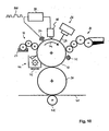
- FIG. 10 shows a further embodiment.
- the constant and well-defined thickness of the dampening solution layer on the surface of the print carrier plays a crucial role for the stability and efficiency of the printing process.
- a printing device is described which allows and monitors a defined, controllable and controllable very thin application of dampening solution.
- the standardized offset printing process usually uses a dampening system consisting of a number of rotating rollers for the application of the dampening solution. Together with a roughened or porous well-water pressure plate results in a sufficiently stable for standard offset printing water film.
- the amount of dampening solution and the thickness of the fountain solution layer can be adjusted for example by the delivery of certain rollers to each other or the speed of the scoop roller.
- the storage effect of the dampening unit and also the the pressure plate to a strongly retarding reaction to Einstellde For the production of a sufficiently stable water film, however, the roughened, strongly water-storing printing plates are essential. From the prior art it is also known to produce a very thin film of water by cooling the printing plate and the consequent condensation of humidity on the printing plate.
- the thickness of the water film is highly dependent on the ambient conditions, such as humidity and temperature, and is to be kept constant over a long period of time.
- FIG. 10 a structure is used which is similar to that in the aforementioned DE-A-101 32 204 described structure which realizes a CTP (Computer-To-Press) method.
- CTP Computer-To-Press
- the printing device allows to produce 10 different printed images on the same surface of the cylindrical print carrier.
- the printing device includes the inking unit 30, with a plurality of rollers, is transferred by the oily ink from the reservoir 38 to the surface of the print carrier 10.
- the inked surface of the print carrier 10 transfers the ink to a blanket cylinder 90. From there, the ink reaches the paper web 40, which is pressed by the impression cylinder 42 against the blanket cylinder 90.
- the dampening unit 18 transfers dampening solution, eg water, from the dampening solution reservoir 24 onto the surface of the print carrier 10 via three rollers.
- the surface of the print carrier 10 can be coated using wetting agents and / or surfactants or by corona and / or Plasma treatment are brought into a more hydrophilic state, as has already been described above.
- the dampening solution layer by energy supply by means of a Laser beam 28 selectively removed and there is the desired image structure.
- the inking by the inking unit 30 then takes place at the ink-attracting areas of the structuring. After patterning, the color may be solidified using a fuser 92.
- a large number of printing processes take place before the surface is restructured.
- the print image located on the print carrier 10 is inked and reprinted once per print, ie there is a multiple inking of the printed image.
- a second mode a new print image is applied to the surface of the print carrier.
- This cleaning station can be pivoted to the print carrier 10 according to the arrow P2 and swung away from it again. Further details of the structure of the printing device after FIG. 10 are in the mentioned DE-A-101 32 204 described.
- an energy source 94 which emits heat energy to the dampening solution film on the surface of the print carrier 10. This energy reduces the thickness of the fountain solution layer.
- the energy source is followed by a layer thickness measuring device 96.
- This layer thickness measuring device 96 determines the actual thickness of the dampening solution film and outputs an electrical signal corresponding to the thickness to a controller 98.
- the controller 98 compares the measured actual thickness with a predetermined target thickness. With a desired-actual value deviation, the energy source 94 is driven so that the thickness of the fountain solution layer is reduced to the desired target thickness.
- the layer thickness measuring device 96 can operate without contact, for example, according to the triangulation method, the transmission method or the capacitive method.
- energy source 94 is one or more IR lamps, radiant heaters, laser systems, laser diodes or heating elements into consideration.
- the interaction of the energy source 94, the Schichtdikkenmeß réelles 96 and the controller 98 may be such that only a monitoring function is performed. If the layer thickness exceeds or falls below a predetermined desired value, then a corresponding warning signal is emitted and then the energy supply for the energy source 94 is readjusted. However, the energy source 94, the Schichtdickenmeß réelle 96 and the controller 98 may also be combined to form a control loop in which the energy source 94 is driven so that at a control deviation between the actual value and target value of the layer thickness minimizes this deviation and preferably to zero is regulated.
- the power source 94 may be driven by the controller using analog voltage regulation or digitally by pulse modulation, as indicated by the signal sequence 100.
- a thick-constant dampening solution film is produced, which is reduced in its layer thickness defined in a subsequent second step.
- the result is a uniform fountain solution layer with a defined and very small thickness.
- the subsequent structuring can thus be carried out with minimal energy and with consistent results. Overall, the print quality is thus increased.
- the advantages of the printing device shown are that an immediate reaction to a change in the layer thickness of the dampening solution layer can be made that a known and defined thickness of the dampening solution layer can be adjusted and that extremely thin fountain solution layers can be produced. Furthermore, the required structuring energy can be minimized, in particular for digital printing methods.
- both an endless belt and a cylinder can be used as the print carrier.
- the transfer to the substrate can be done directly or with the interposition of a blanket cylinder or other intermediate cylinders for a color separation.
- the layer thickness control according to the example according to FIG. 10 can also be used for the other examples.
- a fixation of the applied color by means of a fixing device.
- the cleaning station 46, the dampening unit 18 and the image forming device can be switched inactive and active, for example by pivoting.
Abstract
Description
Die Erfindung betrifft ein Verfahren gemäß den Ansprüchen zum Erzeugen eines Druckbildes auf einem Trägermaterial, bei dem auf der Oberfläche des Druckträgers farbanziehende und farbabstoßende Bereiche entsprechend der Struktur des zu bedruckenden Druckbildes erzeugt werden, wobei die farbabstoßenden Bereiche mit einer Schicht aus einem farbabstoßenden Medium versehen werden, auf die Oberfläche des Druckträgers Farbe aufgetragen wird, die an den farbanziehenden Bereichen anhaftet und die von den farbabstoßenden Bereichen nicht angenommen wird, und bei dem die auf der Oberfläche verteilte Farbe auf das Trägermaterial gedruckt wird.The invention relates to a method according to the claims for producing a printed image on a carrier material, wherein on the surface of the print carrier ink-attracting and ink-repellent regions are generated according to the structure of the printed image to be printed, wherein the ink-repellent regions are provided with a layer of an ink-repellent medium in that ink is applied to the surface of the print substrate, which adheres to the ink-attracting areas and which is not accepted by the ink-repellent areas, and in which the color distributed on the surface is printed on the substrate.
Im Stand der Technik sind wasserlos arbeitende Offset-Druckverfahren bekannt, deren nicht druckende Bereiche fettabstoßend sind und deshalb keine Druckfarbe annehmen. Die druckenden Bereiche sind dagegen fettanziehend und nehmen die fetthaltige Druckfarbe auf. Entsprechend der Struktur des zu druckenden Druckbildes sind auf der Druckplatte farbanziehende und farbabstoßende Bereiche verteilt. Die Druckplatte kann für eine Vielzahl von Umdruckvorgängen verwendet werden. Für jedes Druckbild muß eine neue Platte mit farbanziehenden und farbabstoßenden Bereichen erzeugt werden.In the prior art, waterless offset printing methods are known whose non-printing areas are fat-repellent and therefore do not accept printing ink. The printed areas, on the other hand, are fat-absorbing and pick up the greasy ink. According to the structure of the print image to be printed, ink-attracting and ink-repellent areas are distributed on the printing plate. The printing plate can be used for a variety of transfer printing operations. For each print image, a new plate must be created with ink-attracting and ink-repellent areas.
Aus der
Bei dem mit Wasser arbeitenden Standard-Offset-Verfahren werden auf der Oberfläche des Druckträgers hydrophobe und hydrophile Bereiche entsprechend der Struktur des zu bedruckenden Durckbildes erzeugt. Vor dem Auftragen der Farbe wird unter Verwendung von Auftragswalzen bzw. Sprühvorrichtungen zunächst ein dünnner Feuchtigkeitsfilm auf den Druckträger aufgebracht, der den hydrophilen Bereich des Druckträgers benetzt. Anschließend überträgt die Farbwalze Farbe auf die Oberfläche des Druckträgers, die jedoch ausschließlich die nicht mit dem Feuchtigkeitsfilm bedeckten Bereiche benetzt. Nach dem Einfärben wird schließlich die Farbe auf das Trägermaterial übertragen.In the case of the standard offset process using water, hydrophobic and hydrophilic areas are produced on the surface of the print carrier in accordance with the structure of the print image to be printed. Before application of the paint, a thin film of moisture is first applied to the print substrate using applicator rollers or spraying devices, which wets the hydrophilic area of the print substrate. Subsequently, the inking roller transfers ink to the surface of the print substrate, which wets only those areas not covered by the moisture film. After dyeing, the color is finally transferred to the carrier material.
Im bekannten Offset-Druckverfahren können als Druckträger mehrschichtige prozesslose Thermodruckplatten verwendet werden, vgl. z.B.
Weiterhin ist ein Verfahren aus der
Im Standard-Offset-Verfahren oder Flachdruckverfahren wird die Benetzung der Druckplatte mit dem farbabstoßenden Feuchtmittel durch ein gezieltes Aufrauhen und Strukturieren der Plattenoberfläche erreicht. Die dabei entstehende Oberflächenvergrößerung und Porösität erzeugt Mikrokapillaren und führt zu einer Erhöhung der wirksamen Oberflächenenergie und somit zu einer guten Benetzung bzw. Spreitung des Feuchtmittels. Als weitere Maßnahmen werden beim Offsetdruck benetzungsfördernde Substanzen dem Feuchtmittel zugesetzt. Diese setzen die Oberflächenspannung des Feuchtmittels herab, was ebenso zu einer verbesserten Benetzung der Oberfläche des Druckträgers führt. In diesem Zusammenhang wird auf die Literatur Teschner, H.: Offsettechnik, 5. Auflage, Fellbach, Fachschriften-Verlag 1983, S. 193 - 202 und S. 350, verwiesen.In the standard offset process or planographic printing process, the wetting of the printing plate with the ink-repelling dampening solution is achieved by targeted roughening and structuring of the plate surface. The resulting increase in surface area and porosity produces microcapillaries and leads to an increase in the effective surface energy and thus to a good wetting or spreading of the dampening solution. As further measures, wetting-promoting substances are added to the wetting agent during offset printing. These reduce the surface tension of the fountain solution, which also leads to improved wetting of the surface of the print carrier. In this connection, reference is made to the literature Teschner, H .: Offsettechnik, 5th edition, Fellbach, Fachschriften-Verlag 1983, pp. 193 - 202 and p. 350.
Aus der
Weiterhin wird auf die Patentdokumente
Aus der
Es ist Aufgabe der Erfindung, ein Druckverfahren anzugeben, das für den Digitaldruck mit veränderlichem Druckbild einen vereinfachten Aufbau hat und eine hohe Druckqualität sichert.It is an object of the invention to provide a printing method that has a simplified structure for digital printing with variable print image and ensures high print quality.
Diese Aufgabe wird für ein Verfahren durch die Merkmale des Anspruchs 1 gelöst.This object is achieved for a method by the features of claim 1.
Gemäß der Erfindung wird vor dem Auftragen und Strukturieren der Feuchtmittelschicht eine benetzungsfördernde Substanz in molekularer Schichtdicke auf die Oberfläche des Druckträgers aufgetragen. Demgemäß wird die Funktion Benetzung und Beschichtung voneinander getrennt, wodurch das Feuchtmittel nicht mit Benetzungsmitteln belastet werden muß. Das Verfahren nach der Erfindung gestattet die Verwendung einer sehr glatten Oberfläche des Druckträgers, wodurch die nachfolgenden Prozeßschritte vereinfacht sind, insbesondere die Reinigung vor einer erneuten Strukturierung im Digitaldruck. Außerdem wird der Verschleiß der Druckoberfläche verringert.According to the invention, a wetting-promoting substance in molecular layer thickness is applied to the surface of the print carrier before the application and structuring of the fountain solution layer. Accordingly, the function wetting and coating separated, whereby the dampening solution does not have to be loaded with wetting agents. The method according to the invention allows the use of a very smooth surface of the print carrier, whereby the subsequent process steps are simplified, in particular the cleaning before re-structuring in digital printing. In addition, the wear of the pressure surface is reduced.
Es ist anzumerken, daß in der weiteren Beschreibung häufig der Begriff farbabstoßende oder farbaufnehmende Schicht vorkommt. Diese Schicht ist an die aufzubringende Farbe angepaßt. Zum Beispiel bei einer wasserhaltigen Feuchtmittelschicht und einer ölhaltigen Farbe ist die Feuchtmittelschicht farbabstoßend. Ist die Farbe jedoch wasserhaltig, so ist diese Feuchtmittelschicht farbanziehend. In der Praxis kommen überwiegend ölhaltige Farben zum Einsatz, so daß eine wasserhaltige Feuchtmittelschicht farbabstoßend ist.It should be noted that in the further description often the term color repellent or ink-receptive layer occurs. This layer is adapted to the applied color. For example, in the case of a water-containing fountain solution layer and an oil-containing paint, the fountain solution layer is color-repellent. However, if the paint contains water, this fountain solution layer is color-attracting. In practice, mainly oily inks are used, so that a water-containing fountain solution layer is ink repellent.
Ausführungsbeispiele der Erfindung werden im folgenden anhand der Zeichnung erläutert. Darin zeigt:
- Figur 1
- eine Prinzipdarstellung einer Druckeinrichtung, bei der eine Tensidschicht aufgebracht wird,
- Figur 2
- schematisch einen Querschnitt durch den Druckträger vor und nach der Strukturierung durch einen Laserstrahl,
- Figur 3
- ein Ausführungsbeispiel, bei dem eine hydrophilisierte Schicht strukturiert wird,
- Figur 4
- ein Ausführungsbeispiel, bei dem eine aufgetragene hydrophile Schicht strukturiert wird,
- Figur 5
- einen schematischen Querschnitt durch den Druckträger vor und nach der Strukturierung der hydrophilen Schicht,
- Figur 6
- ein Ausführungsbeispiel, bei dem die Hydrophilisierung durch eine Koronaentladung erfolgt,
- Figur 7
- einen Querschnitt durch eine isolierte Elektrode,
- Figur 8
- eine Anordnung bei einem KunststoffDruckträger,
- Figur 9
- ein Beispiel für eine indirekte Koronaentladung, und
Figur 10- eine Druckeinrichtung mit einer Regelung der Feuchtmittel-Schichtstärke.
- FIG. 1
- a schematic representation of a printing device in which a surfactant layer is applied,
- FIG. 2
- schematically a cross section through the print carrier before and after structuring by a laser beam,
- FIG. 3
- an embodiment in which a hydrophilized layer is structured,
- FIG. 4
- an embodiment in which a coated hydrophilic layer is structured,
- FIG. 5
- a schematic cross section through the print carrier before and after structuring of the hydrophilic layer,
- FIG. 6
- an embodiment in which the hydrophilization is carried out by a corona discharge,
- FIG. 7
- a cross section through an insulated electrode,
- FIG. 8
- an arrangement with a plastic print carrier,
- FIG. 9
- an example of an indirect corona discharge, and
- FIG. 10
- a printing device with a control of dampening solution layer thickness.
In
Die im allgemeinen farbabstoßende Feuchtmittelschicht wird danach durch eine Bilderzeugungsvorrichtung 26 strukturiert. Im vorliegenden Fall wird hierzu Laserstrahlung 28 verwendet. Bei diesem Strukturierungsprozess werden farbanziehende Bereiche und farbabstoßende Bereiche entsprechend der Struktur des zu druckenden Druckbildes erzeugt. Anschließend gelangt die strukturierte Feuchtmittelschicht zu einem Farbwerk 30, welches mit Hilfe der Walzen 32, 34, 36 Farbe aus einem Vorratsbehälter 38 auf die Oberfläche des Druckträgers 10 überträgt. Die ölhaltige Farbe lagert sich an Bereichen ohne wasserhaltiges Feuchtmittel an. Es wird darauf hingewiesen, daß die Farbe auch durch Sprühen, Rakeln oder Kondensieren auf die Oberfläche des Druckträgers 10 übertragen werden kann.The generally ink-repellent fountain solution layer is then patterned by an
Beim Weitertransport des Druckträgers 10 erfolgt ein Umdruck auf ein Trägermaterial 40, im allgemeinen eine Papierbahn. Zum Umdrucken wird das Trägermaterial 40 zwischen zwei Walzen 42, 44 hindurchgeführt. Beim Umdruckprozess können zwischen der Walze 42 und dem Druckträger 10 ein Gummituchzylinder (nicht dargestellt) und weitere Zwischenzylinder geschaltet werden, die eine Farbspaltung bewirken, wie dies aus dem Bereich der Offset-Druckverfahren an sich bekannt ist.Upon further transport of the
Beim weiteren Transport des Druckträgers 10 wird die Oberfläche des Druckträgers 10 in einer Reinigungsstation 46 gereinigt. Hierbei werden die Farbreste sowie auch die Reste der Tensidschicht entfernt. Die Reinigungsstation 46 enthält eine Bürste 48 und eine Wischlippe 50, welche mit der Oberfläche des Druckträgers 10 in Kontakt gebracht werden. Weiterhin kann das Reinigen durch Verwendung von Ultraschall, Hochdruckflüssigkeit und/oder Dampf unterstützt werden. Die Reinigung kann auch unter Einsatz von Reinigungsflüssigkeiten und/oder Lösungsmitteln erfolgen.During further transport of the
Anschließend kann ein neuer Auftrag der benetzungsfördernden Substanz, z.B. ein Tensidauftrag, und ein Feuchtmittelauftrag sowie eine erneute Strukturierung erfolgen. Auf diese Weise kann bei jedem Umlauf des Druckträgers 10 ein neues Druckbild gedruckt werden. Es ist jedoch auch möglich, dasselbe Druckbild mehrfach zu drucken. Die Reinigungsvorrichtung 46, die Vorrichtung 12 und die Vorrichtung 26 werden dann inaktiv geschaltet. Das noch in Farbresten vorhandene Druckbild wird dann durch das Farbwerk 30 erneut eingefärbt und umgedruckt. Bei dieser Betriebsart kann also eine Vielzahl gleicher Druckbilder gedruckt werden.Subsequently, a new application of the wetting-promoting substance, e.g. a surfactant, and a fountain solution and re-structuring done. In this way, with each revolution of the
Vorteile ergeben sich vor allem im Bereich des digitalen Flachdrucks bzw. Offsetdrucks, d.h. einem Flachdruckverfahren bzw. Offsetdruckverfahren mit wechselnder Druckinformation von Druckzyklus zu Druckzyklus. Durch die benetzungsfördernde Schicht 52 kann auf die sonst übliche aufgerauhte, poröse Druckplattenoberfläche verzichtet werden. Stattdessen ist eine glatte Oberfläche des Druckträgers 10 möglich, die mit deutlich geringerem Aufwand zu reinigen ist. Ein schneller und stabiler Reinigungsvorgang ist für ein derartiges digitales Flachdruckverfahren bzw. Offsetdruckverfahren unabdingbar und ein entscheidender Faktor für dessen Effektivität. Demgemäß hat die Oberfläche des Druckträgers 10 eine Rauhheit, die kleiner ist als die beim Standard-Offsetdruckverfahren verwendete Rauhheit. Typischerweise liegt die mittlere Rauhtiefe Rz kleiner als 10 µm, vorzugsweise kleiner als 5 µm. Als Mittenrauhwert Ra ausgedrückt, liegt der Rauhheitswert im Bereich kleiner als 2 µm, vorzugsweise kleiner als 1 µm.Advantages arise above all in the area of digital planographic printing or offset printing, ie a planographic printing method or offset printing method with changing printing information from printing cycle to printing cycle. By the wetting-promoting
Eine Veränderung in der molekularen bzw. atomaren Struktur des Materials des Druckträgers sowie eine permanente und fest mit der Oberfläche des Druckträgers verankerte benetzungsfördernde Schicht ist nicht notwendig. Die hier vorgeschlagene zusätzlich aufgebrachte benetzungsfördernde Substanz, beispielsweise die Tensidschicht 52, entfaltet bereits bei geringsten Mengen ihre benetzungsfördernde Wirkung. Demgemäß ist ihr Einfluss auf die Eigenschaften des Druckträgers 10 in vielerlei Hinsicht vernachlässigbar. Ein weiterer Vorteil ergibt sich aus dem nun möglichen Verzicht auf die beim Offsetdruck in Feuchtmitteln üblicherweise vorhandenen benetzungsfördernden Zusätze.A change in the molecular or atomic structure of the material of the print carrier as well as a permanent and wetting-promoting firmly anchored to the surface of the print carrier Layer is not necessary. The additionally applied wetting-promoting substance proposed here, for example the
Gemäß der
In den folgenden Figuren werden funktionsgleiche Elemente gleich bezeichnet. Diese Figuren dienen der Information und machen die in den
Nach der anschließenden Strukturierung durch die Strukturierungsvorrichtung 26 mittels Laserstrahlung 28 entstehen hydrophile Bereiche und hydrophobe Bereiche entsprechend der Struktur des zu druckenden Druckbildes. Durch das nachgeschaltete Feuchtwerk 18 wird die gesamte nutzbare Oberfläche des Druckträgers 10 mit einer Feuchtmittelschicht in Kontakt gebracht, wobei sich das Feuchtmittel nur an den hydrophilen Bereichen anlagert, so daß farbanziehende Bereiche und farbabstoßende Bereiche entsprechend der vorgenommenen Strukturierung entstehen. Anschließend erfolgt ein Farbauftrag durch das Farbwerk 30, wobei sich die ölhaltige Farbe an Bereichen ohne wasserhaltiges Feuchtmittel anlagert. Anschließend erfolgt das Umdrucken des Druckbildes auf das Trägermaterial 40.After the subsequent structuring by the
Nach dem Weitertransport des Druckträgers 10 wird seine Oberfläche in einer Reinigungsstation 46 gereinigt. Es werden die Farbreste sowie auch die Reste einer eventuellen benetzungsfördernden Substanz entfernt. Anschließend kann ein neuer Strukturierungsprozeß erfolgen.After the further transport of the
Bei dem vorliegenden Beispiel nach
Beim Beispiel nach
Eine vorteilhafte Anordnung ist die Kombination der Hydrophilisierung mit der Reinigung. So kann z.B. sowohl die reinigende als auch die hydrophilisierende Wirkung eines heißen Wasserstrahls bzw. eines heißen Wasserdampfstrahls genutzt werden. Die Reinigung und die Erzeugung der hydrophilen Schicht werden dann in einem einzigen Prozeßschritt durchgeführt.An advantageous arrangement is the combination of hydrophilization with cleaning. Thus, e.g. Both the cleansing and the hydrophilizing effect of a hot water jet or a hot steam jet can be used. The cleaning and the production of the hydrophilic layer are then carried out in a single process step.
In
Aufgrund der sehr dünnen hydrophilen Schicht in molekularer Schichtstärke kann das partielle Entfernen dieser hydrophilen Schicht durch lokale thermische Energiezuführung erfolgen. Aufgrund der geringen Schichtdicke kann der Energieaufwand gering sein. Neben der in den
Auch bei dem Beispiel nach den
Die nachfolgenden Ausführungsbeispiele nach den
Um eine gute Benetzung mit dem im allgemeinen farbabstoßenden Feuchtmittelfilm zu gewährleisten, muß die Oberflächenenergie des Druckträgers 10 mindestens so hoch wie die Oberflächenspannung des Feuchtmittelfilms sein. Dies bedeutet, daß der Wert des Kontaktwinkels zwischen der Oberfläche des Druckträgers 10 und dem Feuchtmittel einen Wert unterhalb von 90° annehmen muß. In der Praxis ist es erforderlich, daß ein Kontaktwinkel von < 25° erreicht werden muß, um den geforderten Flüssigkeitsfilm mit einer Dicke von ca. 1 µm zu erzeugen. Dies stellt eine hohe Anforderung an die Oberflächenenergie des Druckträgers, der, vor allem dann, wenn man den extrem hohen Oberflächenspannungswert von Wasser, nämlich 72 mN/M, als Basis des farbabstoßenden Feuchtmittels berücksichtigt. Kunststoff-Druckträger oder metallische Druckträger können dies ohne weitere Maßnahmen, wie z.B. Aufrauhen, Aufbringen von Tensiden, Erzeugung von Mikrokapillaren etc., nicht leisten. Beispielsweise beträgt der Kontaktwinkel von Wasser zu Polyimid oder Polycarbonat ca. 75°. Selbst Metalloberflächen, die in ihrer reinsten Form sehr hohe Oberflächenenergien und somit kleinste Kontaktwinkel aufweisen, zeigen unter normalen Umgebungsbedingungen relativ hydrophobes Verhalten. Dies hängt wesentlich mit der an Metalloberflächen wirksamen Oxidationsschicht zusammen, die sich unter Normalbedingungen stets ausbildet. Auch geringste Verunreinigungen wirken sich in diesem Zusammenhang negativ für die gewünschte Oberflächenenergie aus. Kontaktwinkel von über 70° sind hiermit in der Praxis häufig anzutreffen.In order to ensure good wetting with the generally ink-repellent dampening solution film, the surface energy of the
Beim Beispiel nach der
Die relativ hohe Spannung an der Elektrode 72 führt zur Ionisation der Luft. Es entsteht eine Koronaentladung, wobei die Oberfläche des Druckträgers 10 mit freien Ionen beschossen wird. Bei einer Kunststoffoberfläche führt dies neben einer Reinigungswirkung, bei der typischerweise organische Verunreinigungen wie Fett, Öl, Wachs etc. entfernt werden, zur Entstehung freier Radikale an der Oberfläche, die im Zusammenhang mit Sauerstoff stark hydrophile Funktionsgruppen bilden. Hierbei handelt es sich vor allem um Carbonylgruppen (-C=O-), Carboxylgruppen (HOOC-), Hydroperoxidgruppen (HOO-) und Hydroxylgruppen (HO-). Bei metallischen Druckträgern steht der Reinigungseffekt im Vordergrund, wobei durch Entfettung der Oberfläche und Beseitigung der Oxidschicht eine Erhöhung der Oberflächenenergie und somit eine Reaktivierung der hydrophilen Eigenschaften von Metallen erreicht wird. Auf diese Weise sind Kontaktwinkel zu Wasser von bis unter 20° bei Kunststoffoberflächen und bei Metalloberflächen erreichbar. Die Koronabehandlung verändert zuvor die physikalischen Oberflächeneigenschaften des Trägers, jedoch nicht seine mechanischen Eigenschaften. Es sind keine sichtbaren Veränderungen z.B. mit einem Rasterelektronen-Mikroskop nachweisbar. Durch Variation der Höhe der Spannung bzw. der Frequenz des Hochspannungsgenerators läßt sich die Wirkung auf die Oberfläche des Druckträgers 10 beeinflussen und auf das jeweilige Trägermaterial abstimmen. Die Hydrophilisierung kann durch Zuführung von Prozeßgasen, vorzugsweise Sauerstoff oder Stickstoff, verbessert werden.The relatively high voltage at the
In
Alternativ kann auch eine Niederdruckplasmabehandlung eingesetzt werden, die die Oberflächenenergie an der Oberfläche des Druckträgers 10 erhöht. Hierbei wird unter Vakuumbedingungen, beispielsweise im Bereich von 0,3 bis 20 mbar, eine Hochspannungsentladung erzeugt, durch die Prozeßgas ionisiert und in den Plasmazustand versetzt wird. Dieses Plasma tritt mit der Oberfläche des Druckträgers 10 in Kontakt. Die Wirkung des Plasmas ist mit der Wirkung der Koronabehandlung zu vergleichen.Alternatively, a low-pressure plasma treatment can be used, which increases the surface energy at the surface of the
Mithilfe des in den
Durch das beschriebene Hydrophilisierungsverfahren ergeben sich verschiedene Vorteile. Es kann auf die aufgerauhte poröse Druckplattenoberfläche wie beim Standard-Offest-Druckverfahren verzichtet werden. Stattdessen ist eine sehr glatte Oberfläche möglich, deren Rauhheitsbereich sehr niedrig ist, beispielsweise in einem Bereich des Mittenrauhwerts Ra < 1 µm. Dadurch ist ein schneller und stabiler Reinigungsvorgang für die Oberfläche möglich. Für den beschriebenen Druckprozeß ist weder eine permanente Veränderung in der molekularen bzw. atomaren Struktur des Materials des Druckträgers noch eine permanente und fest mit dem Druckträger verankerte benetzungsfördernde Schicht notwendig. Durch den beschriebenen Hydrophilisierungsprozeß kann der Druckträger ohne Rücksichtnahme auf die Oberflächenenergie hinsichtlich weiterer Anforderungen optimiert werden.The described hydrophilization process offers various advantages. It is possible to dispense with the roughened porous printing plate surface as in the standard offest printing method. Instead, a very smooth surface is possible whose roughness range is very low, for example in a region of the average roughness value R a <1 μm. This allows a quick and stable cleaning process for the surface. For the printing process described, neither a permanent change in the molecular or atomic structure of the material of the print carrier nor a permanent and firmly anchored to the print carrier wetting-promoting layer necessary. Due to the described hydrophilization process, the print carrier can be optimized without regard to the surface energy with regard to further requirements.
Der beschriebene Hydrophilisierungsprozeß erlaubt ferner den Verzicht auf die im Offset-Druck für Feuchtmittel verwendeten benetzungsfördernden Zusätze. Ein weiterer Auftrag zusätzlicher benetzungsfördernder Substanzen ist nicht mehr erforderlich. Dies vermeidet eine relativ komplizierte Prozeßführung und reduziert den Mehraufwand an Verbrauchsstoffen. Ein weiterer Vorteil liegt auch in der Reinigungswirkung des Hydrophilisierungsverfahrens. Es unterstützt den für das digitale Druckverfahren notwendigen Reinigungsprozeß und reduziert somit weiter den erforderlichen Hardwareaufwand.The described hydrophilization process also allows the waiver of the wetting-promoting additives used in offset printing for dampening solution. Another order of additional wetting-promoting substances is no longer required. This avoids a relatively complicated process management and reduces the overhead of consumables. Another advantage lies in the cleaning effect of the hydrophilization process. It supports the cleaning process necessary for the digital printing process and thus further reduces the required hardware expenditure.
Beim Ausführungsbeispiel nach
Die in
Das Feuchtwerk 18 überträgt über drei Walzen Feuchtmittel, z.B. Wasser, aus dem Feuchtmittelvorratsbehälter 24 auf die Oberfläche des Druckträgers 10. Vor dem Auftragen der Feuchtmittelschicht kann die Oberfläche des Druckträgers 10 unter Verwendung von Netzmitteln und/oder Tensiden oder durch eine Korona- und/oder Plasma-Behandlung in einen hydrophileren Zustand gebracht werden, wie dies weiter oben bereits beschrieben worden ist. Im weiteren Verlauf wird die Feuchtmittelschicht durch Energiezufuhr mittels eines Laserstrahls 28 selektiv entfernt und es entsteht die gewünschte Bildstruktur. Wie erwähnt, erfolgt danach die Einfärbung durch das Farbwerk 30 an den farbanziehenden Bereichen der Strukturierung. Nach dem Strukturieren kann die Farbe mithilfe einer Fixiereinrichtung 92 verfestigt werden.The dampening
Auch bei diesem Beispiel sind zwei Betriebsarten möglich. Bei einer ersten Betriebsart erfolgt vor einer erneuten Strukturierung der Oberfläche eine Vielzahl von Druckvorgängen. Das auf dem Druckträger 10 befindliche Druckbild wird je Druck einmal eingefärbt und umgedruckt, d.h. es erfolgt ein mehrfaches Einfärben des Druckbildes. In einer zweiten Betriebsart wird auf die Oberfläche des Druckträgers ein neues Druckbild aufgebracht. Davor ist die bisherige strukturierte farbabstoßende Schicht sowie die Farbreste zu entfernen, wofür die Reinigungsstation 46 vorgesehen ist. Diese Reinigungsstation kann an den Druckträger 10 gemäß dem Pfeil P2 herangeschwenkt und wieder von diesem weggeschwenkt werden. Weitere Einzelheiten des Aufbaus der Druckeinrichtung nach
In Transportrichtung P1 gesehen ist nach dem Feuchtwerk 18 eine Energiequelle 94 angeordnet, die Wärmeenergie an den Feuchtmittelfilm auf der Oberfläche des Druckträgers 10 abgibt. Mithilfe dieser Energie wird die Dicke der Feuchtmittelschicht verringert. In Transportrichtung gesehen ist der Energiequelle ein Schichtdickenmeßgerät 96 nachgelagert. Dieses Schichtdickenmeßgerät 96 ermittelt die aktuelle Dicke des Feuchtmittelfilms und gibt ein der Dicke entsprechendes elektrisches Signal an eine Steuerung 98 ab. Die Steuerung 98 vergleicht die gemessene Ist-Dicke mit einer vorgegebenen Soll-Dicke. Bei einer Soll-Ist-Wert-Abweichung wird die Energiequelle 94 so angesteuert, daß die Dicke der Feuchtmittelschicht auf die gewünschte Soll-Dicke reduziert wird.As seen in the transport direction P1, after the dampening
Das Schichtdickenmeßgerät 96 kann beispielsweise nach dem Triangulationsverfahren, dem Transmissionsverfahren oder dem kapazitiven Verfahren berührungslos arbeiten. Als Energiequelle 94 kommt eine oder mehrere IR-Lampen, Heizstrahler, Lasersysteme, Laserdioden oder Heizelemente in Betracht.The layer
Das Zusammenwirken der Energiequelle 94, des Schichtdikkenmeßgeräts 96 und der Steuerung 98 kann derart sein, daß lediglich eine Überwachungsfunktion vorgenommen wird. Wenn die Schichtdicke einen vorgegebenen Soll-Wert überschreitet oder unterschreitet, so wird ein entsprechendes Warnsignal abgegeben und darauf hin die Energiezufuhr für die Energiequelle 94 neu eingestellt. Die Energiequelle 94, das Schichtdickenmeßgerät 96 und die Steuerung 98 können jedoch auch zu einem Regelkreis zusammengeschlossen werden, bei dem die Energiequelle 94 so angesteuert wird, daß bei einer Regelabweichung zwischen Ist-Wert und Soll-Wert der Schichtdicke diese Regelabweichung minimiert und vorzugsweise auf Null geregelt wird.The interaction of the
Die Energiequelle 94 kann durch die Steuerung mithilfe einer analogen Spannungsregelung oder digital durch eine Pulsmodulation angesteuert werden, wie dies durch die Signalfolge 100 angedeutet ist.The
Gemäß dem Beispiel nach
Es sind zahlreiche weitere Variationen der vorbeschriebenen Ausführungsbeispiele möglich. Beispielsweise kann als Druckträger sowohl ein Endlosband als auch ein Zylinder verwendet werden. Der Umdruck auf das Trägermaterial kann direkt erfolgen oder unter Zwischenschaltung eines Gummituchzylinders bzw. weiteren Zwischenzylindern für eine Farbspaltung. Die Schichtdickenregelung gemäß dem Beispiel nach
Bezugszeichenliste
- 10
- Druckträger
- 12
- Vorbehandlungsvorrichtung
- 13
- Behälter
- 14
- Schöpfwalze
- 16
- Auftragswalze
- 18
- Feuchtwerk
- 20
- Schöpfwalze
- 22
- Auftragswalze
- 24
- Feuchtmittelvorratsbehälter
- 26
- Bilderzeugungsvorrichtung
- 28
- Laserstrahl
- 30
- Farbwerk
- 32, 34, 36
- Walzen
- 38
- Vorratsbehälter
- 40
- Trägermaterial
- 42, 44
- Walzen
- 46
- Reinigungsstation
- 48
- Bürste
- 50
- Wischlippe
- 52
- Tensidschicht
- 54
- Feuchtmittelschicht
- 60
- Dampfvorrichtung
- 62
- Absaugvorrichtung
- 64
- hydrophobe Bereiche
- 68
- hydrophile Bereiche
- 70
- Hochspannungsgenerator
- 72
- Elektrode
- 74
- Schleifkontakt
- 76
- metallischer Kern
- 78
- Keramikmantel
- 80
- Elektrodenplatte
- 82, 84
- Elektrode
- 86
- Gebläse
- 90
- Gummituchzylinder
- 92
- Fixiereinrichtung
- 94
- Energiequelle
- 96
- Schichtdickenmeßgerät
- 98
- Steuerung
- 100
- Signalfolge
- P1
- Transportrichtung
- P2
- Richtungspfeil
- 10
- print carrier
- 12
- pretreatment device
- 13
- container
- 14
- scoop roller
- 16
- applicator roll
- 18
- dampening
- 20
- scoop roller
- 22
- applicator roll
- 24
- Dampening solution reservoir
- 26
- Imaging device
- 28
- laser beam
- 30
- inking
- 32, 34, 36
- roll
- 38
- reservoir
- 40
- support material
- 42, 44
- roll
- 46
- cleaning station
- 48
- brush
- 50
- wiper lip
- 52
- surfactant
- 54
- Fountain solution layer
- 60
- steam device
- 62
- suction
- 64
- hydrophobic areas
- 68
- hydrophilic areas
- 70
- High voltage generator
- 72
- electrode
- 74
- sliding contact
- 76
- metallic core
- 78
- ceramic shell
- 80
- electrode plate
- 82, 84
- electrode
- 86
- fan
- 90
- Blanket cylinder
- 92
- fixing
- 94
- energy
- 96
- Coating Thickness
- 98
- control
- 100
- signal sequence
- P1
- transport direction
- P2
- arrow
Claims (10)
- A method for generating a print image on a carrier material (40),
in which the surface of a print carrier (40) is coated with an ink-repelling or an ink-attracting layer of a fountain solution (54),
in a structuring process, ink-attracting regions and ink-repelling regions are generated on the surface coated with the liquid fountain solution (54) corresponding to the structure of the print image to be printed,
ink that adheres to the ink-attracting regions and that is not absorbed by the ink-repelling regions is applied on the surface,
the applied ink is transferred onto the carrier material (40) in the further course,
before a new structuring process on the same surface of the print carrier (10), this surface is cleaned and re-coated with an ink-repelling or ink-attracting layer of fountain solution (54),
before the application of the ink-repelling or ink-attracting layer of fountain solution (54) a wetting-aiding substance (52) is applied in molecular layer thickness on the surface of the print carrier (10),
a surfactant with hydrophilic molecule sections is used as a wetting-aiding substance (52),
and in which the layer thickness for the wetting-aiding substance (52) is smaller than 0.1 µm. - The method according to claim 1, in which a fountain solution (54) based on water is used as an ink-repelling layer.
- The method according to one of the preceding claims, in which the layer thickness of the ink-repelling layer (54) is smaller than 1 µm.
- The method according to one of the preceding claims, in which the average roughness Rz of the surface of the print carrier (10) is smaller than 10 µm, preferably smaller than 5 µm.
- The method according to one of the preceding claims, in which the average roughness value Ra of the surface of the print carrier (10) is smaller than 2 µm, preferably smaller than 1 µm.
- The method according to one of the preceding claims, in which digitally-controlled radiation is used for structuring.
- The method according to claim 6, in which the radiation of a laser system, a laser, laser diodes, LEDs or a laser diode array is used.
- The method according to one of the preceding claims, in which a plurality of printing events takes place before a restructuring of the surface, wherein the print carrier (10) is inked several times successively.
- The method according to one of the preceding claims, in which the surface of the print carrier (10) is a continuous band or a generated cylinder surface.
- The method according to one of the preceding claims, in which an ink separation takes place before the transfer of the ink onto the carrier material (40).
Applications Claiming Priority (3)
| Application Number | Priority Date | Filing Date | Title |
|---|---|---|---|
| DE10206937 | 2002-02-19 | ||
| DE10206937A DE10206937A1 (en) | 2002-02-19 | 2002-02-19 | Method and device for printing, a wetting-promoting substance having a molecular layer thickness being applied before the application of a dampening solution |
| PCT/EP2003/001496 WO2003070481A1 (en) | 2002-02-19 | 2003-02-14 | Printing device and method, in which a humidity promoter is applied prior to the ink-repellent or ink-receptive layer |
Publications (2)
| Publication Number | Publication Date |
|---|---|
| EP1476313A1 EP1476313A1 (en) | 2004-11-17 |
| EP1476313B1 true EP1476313B1 (en) | 2008-10-29 |
Family
ID=27674746
Family Applications (1)
| Application Number | Title | Priority Date | Filing Date |
|---|---|---|---|
| EP03708101A Expired - Lifetime EP1476313B1 (en) | 2002-02-19 | 2003-02-14 | Printing device and method, in which a humidity promoter is applied prior to the ink-repellent or ink-receptive layer |
Country Status (5)
| Country | Link |
|---|---|
| US (1) | US7191705B2 (en) |
| EP (1) | EP1476313B1 (en) |
| AT (1) | ATE412533T1 (en) |
| DE (2) | DE10206937A1 (en) |
| WO (1) | WO2003070481A1 (en) |
Families Citing this family (56)
| Publication number | Priority date | Publication date | Assignee | Title |
|---|---|---|---|---|
| ITMI20031131A1 (en) * | 2003-06-05 | 2004-12-06 | Omet Srl | METHOD AND DEVICE FOR CLEANING A CYLINDER OF |
| CA2643249A1 (en) | 2006-02-21 | 2007-08-30 | Moore Wallace North America, Inc. | Systems and methods for high speed variable printing |
| US9463643B2 (en) | 2006-02-21 | 2016-10-11 | R.R. Donnelley & Sons Company | Apparatus and methods for controlling application of a substance to a substrate |
| US8881651B2 (en) | 2006-02-21 | 2014-11-11 | R.R. Donnelley & Sons Company | Printing system, production system and method, and production apparatus |
| US8967044B2 (en) | 2006-02-21 | 2015-03-03 | R.R. Donnelley & Sons, Inc. | Apparatus for applying gating agents to a substrate and image generation kit |
| US8869698B2 (en) * | 2007-02-21 | 2014-10-28 | R.R. Donnelley & Sons Company | Method and apparatus for transferring a principal substance |
| US8120778B2 (en) | 2009-03-06 | 2012-02-21 | Imra America, Inc. | Optical scanning and imaging systems based on dual pulsed laser systems |
| US9701120B2 (en) | 2007-08-20 | 2017-07-11 | R.R. Donnelley & Sons Company | Compositions compatible with jet printing and methods therefor |
| WO2009025809A1 (en) | 2007-08-20 | 2009-02-26 | Rr Donnelley | Nanoparticle-based compositions compatible with jet printing and methods therefor |
| US8256346B2 (en) * | 2008-08-06 | 2012-09-04 | Lewis Thomas E | Plateless lithographic printing |
| US8807029B2 (en) | 2008-08-06 | 2014-08-19 | Thomas E. Lewis | Plateless lithographic printing |
| WO2011046780A1 (en) * | 2009-10-13 | 2011-04-21 | Nanda Nathan | Pulsed high-power laser apparatus and methods |
| US20120038726A1 (en) * | 2010-08-13 | 2012-02-16 | Palo Alto Research Center Incorporated | Thermal ink transfer using endless belt |
| US20120103213A1 (en) * | 2010-10-29 | 2012-05-03 | Palo Alto Research Center Incorporated | Ink Rheology Control Subsystem for a Variable Data Lithography System |
| US20120103214A1 (en) * | 2010-10-29 | 2012-05-03 | Palo Alto Research Center Incorporated | Heated Inking Roller for a Variable Data Lithography System |
| US20120103217A1 (en) | 2010-10-29 | 2012-05-03 | Palo Alto Research Center Incorporated | Cleaning Subsystem for a Variable Data Lithography System |
| US20120103219A1 (en) * | 2010-10-29 | 2012-05-03 | Palo Alto Research Center Incorporated | Ink Transfer Subsystem for a Variable Data Lithography System |
| US20120274914A1 (en) | 2011-04-27 | 2012-11-01 | Palo Alto Research Center Incorporated | Variable Data Lithography System for Applying Multi-Component Images and Systems Therefor |
| US20120103212A1 (en) * | 2010-10-29 | 2012-05-03 | Palo Alto Research Center Incorporated | Variable Data Lithography System |
| US20120103221A1 (en) | 2010-10-29 | 2012-05-03 | Palo Alto Research Center Incorporated | Cleaning Method for a Variable Data Lithography System |
| US20120103218A1 (en) * | 2010-10-29 | 2012-05-03 | Palo Alto Research Center Incorporated | Method of Ink Rheology Control in a Variable Data Lithography System |
| US8508791B1 (en) | 2012-01-23 | 2013-08-13 | Xerox Corporation | Image feedforward laser power control for a multi-mirror based high power imager |
| US9021948B2 (en) | 2011-04-27 | 2015-05-05 | Xerox Corporation | Environmental control subsystem for a variable data lithographic apparatus |
| US9138982B2 (en) | 2011-04-27 | 2015-09-22 | Xerox Corporation | Image data based temperature control of a keyless inker |
| US8991310B2 (en) * | 2011-04-27 | 2015-03-31 | Palo Alto Research Center Incorporated | System for direct application of dampening fluid for a variable data lithographic apparatus |
| US8347787B1 (en) * | 2011-08-05 | 2013-01-08 | Palo Alto Research Center Incorporated | Variable data lithography apparatus employing a thermal printhead subsystem |
| US9021949B2 (en) * | 2012-02-06 | 2015-05-05 | Palo Alto Research Center Incorporated | Dampening fluid recovery in a variable data lithography system |
| US9032874B2 (en) | 2012-03-21 | 2015-05-19 | Xerox Corporation | Dampening fluid deposition by condensation in a digital lithographic system |
| US8950322B2 (en) * | 2012-03-21 | 2015-02-10 | Xerox Corporation | Evaporative systems and methods for dampening fluid control in a digital lithographic system |
| US20130327237A1 (en) * | 2012-06-12 | 2013-12-12 | Xerox Corportation | Systems and methods for implementing digital offset lithographic printing techniques |
| US8943961B2 (en) | 2012-07-10 | 2015-02-03 | Xerox Corporation | Systems and methods for facilitating oil delivery in digital offset lithographic printing techniques |
| US9639050B2 (en) | 2012-07-12 | 2017-05-02 | Xerox Corporation | Electrophotographic patterning of an image definition material |
| US9529307B2 (en) | 2012-07-12 | 2016-12-27 | Palo Alto Research Center Incorporated | Imaging system for patterning of an image definition material by electro-wetting and methods therefor |
| US9316993B2 (en) | 2012-07-12 | 2016-04-19 | Xerox Corporation | Electrophotographic patterning of an image definition material |
| US9316994B2 (en) | 2012-07-12 | 2016-04-19 | Xerox Corporation | Imaging system with electrophotographic patterning of an image definition material and methods therefor |
| US8586277B1 (en) * | 2012-07-12 | 2013-11-19 | Palo Alto Research Center Incorporated | Patterning of an image definition material by electro-wetting |
| US8833254B2 (en) | 2012-07-12 | 2014-09-16 | Xerox Corporation | Imaging system with electrophotographic patterning of an image definition material and methods therefor |
| US8919252B2 (en) | 2012-08-31 | 2014-12-30 | Xerox Corporation | Methods and systems for ink-based digital printing with multi-component, multi-functional fountain solution |
| US9592698B2 (en) | 2012-08-31 | 2017-03-14 | Xerox Corporation | Imaging member for offset printing applications |
| US9561677B2 (en) | 2012-08-31 | 2017-02-07 | Xerox Corporation | Imaging member for offset printing applications |
| US9616654B2 (en) | 2012-08-31 | 2017-04-11 | Xerox Corporation | Imaging member for offset printing applications |
| US9327487B2 (en) * | 2012-08-31 | 2016-05-03 | Xerox Corporation | Variable lithographic printing process |
| US9567486B2 (en) | 2012-08-31 | 2017-02-14 | Xerox Corporation | Imaging member for offset printing applications |
| US9956801B2 (en) | 2012-08-31 | 2018-05-01 | Xerox Corporation | Printing plates doped with release oil |
| US9315057B2 (en) | 2013-01-16 | 2016-04-19 | Seiko Epson Corporation | Belt cleaning apparatus and recording apparatus |
| US20140261030A1 (en) * | 2013-03-15 | 2014-09-18 | Xerox Corporation | Systems for applying dampening fluid to an imaging member for ink-based digital printing |
| US20140318397A1 (en) * | 2013-04-30 | 2014-10-30 | Xerox Corporation | Systems and methods for implementing digital offset lithographic printing techniques with a plurality of intermediate transfers |
| US9056452B2 (en) * | 2013-05-22 | 2015-06-16 | Xerox Corporation | Systems and methods for ink-based digital printing using variable data lithography inkjet imaging system |
| US9126452B2 (en) | 2013-07-29 | 2015-09-08 | Xerox Corporation | Ultra-fine textured digital lithographic imaging plate and method of manufacture |
| US9272532B2 (en) | 2013-07-29 | 2016-03-01 | Palo Alto Research Center Incorporated | Molded textured imaging blanket surface |
| US9250516B2 (en) | 2013-07-29 | 2016-02-02 | Palo Alto Research Center Incorporated | Method of making a molded textured imaging blanket surface |
| US9630423B2 (en) * | 2013-09-16 | 2017-04-25 | Xerox Corporation | Hydrophilic imaging member surface material for variable data ink-based digital printing systems and methods for manufacturing hydrophilic imaging member surface materials |
| US20150116444A1 (en) | 2013-10-31 | 2015-04-30 | Palo Alto Research Center Incorporated | Imaging Blanket with Dispersed Carbon and Micro-Texture Surface |
| US10022951B2 (en) | 2014-04-28 | 2018-07-17 | Xerox Corporation | Systems and methods for implementing a vapor condensation technique for delivering a uniform layer of dampening solution in an image forming device using a variable data digital lithographic printing process |
| US20150376768A1 (en) * | 2014-06-30 | 2015-12-31 | Palo Alto Research Center Incorporated | Systems and methods for implementing digital vapor phase patterning using variable data digital lithographic printing techniques |
| US10589515B2 (en) | 2016-08-23 | 2020-03-17 | Palo Alto Research Center Incorporated | Cleaning system architecture with recirculating bath for variable data lithographic printing |
Family Cites Families (14)
| Publication number | Priority date | Publication date | Assignee | Title |
|---|---|---|---|---|
| ATE58605T1 (en) * | 1986-07-11 | 1990-12-15 | Siemens Ag | THERMAL TRANSFER PRINTING DEVICE. |
| JPH03505307A (en) | 1988-02-26 | 1991-11-21 | ジーメンス アクチエンゲゼルシヤフト | Method and apparatus for printing by thermal latent image coloring |
| US6006666A (en) | 1992-05-20 | 1999-12-28 | Man Roland Druckmaschinen Ag | Method and apparatus for erasing the ink-carrying layer from the surface of an image-containing printing form |
| DE4216636C2 (en) | 1992-05-20 | 1995-11-23 | Roland Man Druckmasch | Process and device for erasing and hydrophilizing a printing form imaged by means of a thermal transfer process |
| US5379698A (en) | 1992-07-20 | 1995-01-10 | Presstek, Inc. | Lithographic printing members for use with laser-discharge imaging |
| DE4426012C2 (en) * | 1994-07-22 | 1998-05-20 | Roland Man Druckmasch | Erasable printing form, its use and methods for erasing and regenerating the printing form |
| US5816161A (en) | 1994-07-22 | 1998-10-06 | Man Roland Druckmaschinen Ag | Erasable printing plate having a smooth pore free metallic surface |
| DE59701516D1 (en) * | 1996-03-29 | 2000-05-31 | Oce Printing Systems Gmbh | PRINTING METHOD FOR PRINTING A CARRIER MATERIAL |
| US6232037B1 (en) * | 1996-10-11 | 2001-05-15 | Fuji Photo Film Co., Ltd. | Lithographic printing plate, method for producing lithographic printing plate, and method for producing support for lithographic printing plate |
| WO1998032608A1 (en) | 1997-01-27 | 1998-07-30 | Oce Printing Systems Gmbh | Method and device for printing on a carrier material using a structured ice layer |
| DE19826377A1 (en) * | 1998-06-12 | 1999-12-16 | Heidelberger Druckmasch Ag | Printing press and printing process |
| KR100343912B1 (en) | 1998-09-21 | 2002-07-20 | 프레스텍, 인크. | Lithographic Printing Plates For Use With Laser Imaging Apparatus |
| DE10132204A1 (en) * | 2001-07-03 | 2003-01-30 | Oce Printing Systems Gmbh | Production of different printed images with the same print substrate using a printer with an integral cleaning device so that the same print substrate can be used for different images without renewal or removal |
| DE10206936A1 (en) * | 2002-02-19 | 2003-09-11 | Oce Printing Systems Gmbh | Digital printing process and printing device with a cup-shaped print carrier |
-
2002
- 2002-02-19 DE DE10206937A patent/DE10206937A1/en not_active Withdrawn
-
2003
- 2003-02-14 AT AT03708101T patent/ATE412533T1/en not_active IP Right Cessation
- 2003-02-14 US US10/505,237 patent/US7191705B2/en not_active Expired - Fee Related
- 2003-02-14 EP EP03708101A patent/EP1476313B1/en not_active Expired - Lifetime
- 2003-02-14 DE DE50310699T patent/DE50310699D1/en not_active Expired - Lifetime
- 2003-02-14 WO PCT/EP2003/001496 patent/WO2003070481A1/en not_active Application Discontinuation
Also Published As
| Publication number | Publication date |
|---|---|
| US7191705B2 (en) | 2007-03-20 |
| US20050178281A1 (en) | 2005-08-18 |
| EP1476313A1 (en) | 2004-11-17 |
| DE50310699D1 (en) | 2008-12-11 |
| ATE412533T1 (en) | 2008-11-15 |
| DE10206937A1 (en) | 2003-09-04 |
| WO2003070481A1 (en) | 2003-08-28 |
Similar Documents
| Publication | Publication Date | Title |
|---|---|---|
| EP1476313B1 (en) | Printing device and method, in which a humidity promoter is applied prior to the ink-repellent or ink-receptive layer | |
| EP1478512B1 (en) | Method and device for printing wherein a hydrophilic layer is produced and structured | |
| EP0963839B1 (en) | Printing machine and printing process | |
| EP1616713B1 (en) | Reusable printing plate | |
| DE10132204A1 (en) | Production of different printed images with the same print substrate using a printer with an integral cleaning device so that the same print substrate can be used for different images without renewal or removal | |
| DE10227054B4 (en) | Reusable printing form, printing unit and printing machine with it as well as methods for imaging the printing form | |
| EP1177914B1 (en) | Method to reclaim a reusable printing plate | |
| EP1151857B1 (en) | Controlled imaging formation and erasure on a metallic titanium printing form | |
| WO1998032608A1 (en) | Method and device for printing on a carrier material using a structured ice layer | |
| EP0730953A2 (en) | Process and apparatus for intaglio printing | |
| DE10360108A1 (en) | Printing plate, for the printing cylinder of an offset printing press has a surface of a shape memory material which is subjected to two different temperatures to give an erasure for repeated use | |
| EP1476303B1 (en) | Printing method and device, using controlled radiation outlets for creating a structure | |
| DE10206944A1 (en) | Method and device for printing, the thickness of the dampening solution layer being measured and reduced | |
| EP1476304B1 (en) | Method and device for printing wherein the printing cylinder or plate is hydrophilized by free ions | |
| DE10213802B4 (en) | Method of preserving image information of an imaged printing form | |
| EP1401660B1 (en) | Method and device for producing different printed images on the same print substrate | |
| EP1476311B1 (en) | Digital printing method and printing device having a cup-shaped printing carrier | |
| DE10311514B4 (en) | Method for operating an offset printing unit and offset printing unit | |
| DE10206943A1 (en) | Production of different printed images with the same print substrate using a printer with an integral cleaning device so that the same print substrate can be used for different images without renewal or removal | |
| WO2008087196A1 (en) | Method for the transfer of structural data, and device therefor | |
| DE10208250A1 (en) | Printing process gives a printing structure to the plate, using electromagnetic rays to remove water from the surfaces required to take up ink for printing, leaving other zones which reject ink |
Legal Events
| Date | Code | Title | Description |
|---|---|---|---|
| PUAI | Public reference made under article 153(3) epc to a published international application that has entered the european phase |
Free format text: ORIGINAL CODE: 0009012 |
|
| 17P | Request for examination filed |
Effective date: 20040721 |
|
| AK | Designated contracting states |
Kind code of ref document: A1 Designated state(s): AT BE BG CH CY CZ DE DK EE ES FI FR GB GR HU IE IT LI LU MC NL PT SE SI SK TR |
|
| 17Q | First examination report despatched |
Effective date: 20060329 |
|
| GRAP | Despatch of communication of intention to grant a patent |
Free format text: ORIGINAL CODE: EPIDOSNIGR1 |
|
| GRAS | Grant fee paid |
Free format text: ORIGINAL CODE: EPIDOSNIGR3 |
|
| GRAA | (expected) grant |
Free format text: ORIGINAL CODE: 0009210 |
|
| AK | Designated contracting states |
Kind code of ref document: B1 Designated state(s): AT BE BG CH CY CZ DE DK EE ES FI FR GB GR HU IE IT LI LU MC NL PT SE SI SK TR |
|
| REG | Reference to a national code |
Ref country code: GB Ref legal event code: FG4D Free format text: NOT ENGLISH |
|
| REG | Reference to a national code |
Ref country code: CH Ref legal event code: EP |
|
| REG | Reference to a national code |
Ref country code: IE Ref legal event code: FG4D Free format text: LANGUAGE OF EP DOCUMENT: GERMAN |
|
| REF | Corresponds to: |
Ref document number: 50310699 Country of ref document: DE Date of ref document: 20081211 Kind code of ref document: P |
|
| NLV1 | Nl: lapsed or annulled due to failure to fulfill the requirements of art. 29p and 29m of the patents act | ||
| PG25 | Lapsed in a contracting state [announced via postgrant information from national office to epo] |
Ref country code: ES Free format text: LAPSE BECAUSE OF FAILURE TO SUBMIT A TRANSLATION OF THE DESCRIPTION OR TO PAY THE FEE WITHIN THE PRESCRIBED TIME-LIMIT Effective date: 20090209 Ref country code: BG Free format text: LAPSE BECAUSE OF FAILURE TO SUBMIT A TRANSLATION OF THE DESCRIPTION OR TO PAY THE FEE WITHIN THE PRESCRIBED TIME-LIMIT Effective date: 20090129 |
|
| PG25 | Lapsed in a contracting state [announced via postgrant information from national office to epo] |
Ref country code: SI Free format text: LAPSE BECAUSE OF FAILURE TO SUBMIT A TRANSLATION OF THE DESCRIPTION OR TO PAY THE FEE WITHIN THE PRESCRIBED TIME-LIMIT Effective date: 20081029 Ref country code: FI Free format text: LAPSE BECAUSE OF FAILURE TO SUBMIT A TRANSLATION OF THE DESCRIPTION OR TO PAY THE FEE WITHIN THE PRESCRIBED TIME-LIMIT Effective date: 20081029 Ref country code: PT Free format text: LAPSE BECAUSE OF FAILURE TO SUBMIT A TRANSLATION OF THE DESCRIPTION OR TO PAY THE FEE WITHIN THE PRESCRIBED TIME-LIMIT Effective date: 20090330 Ref country code: NL Free format text: LAPSE BECAUSE OF FAILURE TO SUBMIT A TRANSLATION OF THE DESCRIPTION OR TO PAY THE FEE WITHIN THE PRESCRIBED TIME-LIMIT Effective date: 20081029 |
|
| REG | Reference to a national code |
Ref country code: IE Ref legal event code: FD4D |
|
| PG25 | Lapsed in a contracting state [announced via postgrant information from national office to epo] |
Ref country code: EE Free format text: LAPSE BECAUSE OF FAILURE TO SUBMIT A TRANSLATION OF THE DESCRIPTION OR TO PAY THE FEE WITHIN THE PRESCRIBED TIME-LIMIT Effective date: 20081029 Ref country code: DK Free format text: LAPSE BECAUSE OF FAILURE TO SUBMIT A TRANSLATION OF THE DESCRIPTION OR TO PAY THE FEE WITHIN THE PRESCRIBED TIME-LIMIT Effective date: 20081029 Ref country code: IE Free format text: LAPSE BECAUSE OF FAILURE TO SUBMIT A TRANSLATION OF THE DESCRIPTION OR TO PAY THE FEE WITHIN THE PRESCRIBED TIME-LIMIT Effective date: 20081029 |
|
| BERE | Be: lapsed |
Owner name: OCE PRINTING SYSTEMS G.M.B.H. Effective date: 20090228 |
|
| PG25 | Lapsed in a contracting state [announced via postgrant information from national office to epo] |
Ref country code: CZ Free format text: LAPSE BECAUSE OF FAILURE TO SUBMIT A TRANSLATION OF THE DESCRIPTION OR TO PAY THE FEE WITHIN THE PRESCRIBED TIME-LIMIT Effective date: 20081029 Ref country code: IT Free format text: LAPSE BECAUSE OF FAILURE TO SUBMIT A TRANSLATION OF THE DESCRIPTION OR TO PAY THE FEE WITHIN THE PRESCRIBED TIME-LIMIT Effective date: 20081029 Ref country code: SE Free format text: LAPSE BECAUSE OF FAILURE TO SUBMIT A TRANSLATION OF THE DESCRIPTION OR TO PAY THE FEE WITHIN THE PRESCRIBED TIME-LIMIT Effective date: 20090129 |
|
| PLBE | No opposition filed within time limit |
Free format text: ORIGINAL CODE: 0009261 |
|
| STAA | Information on the status of an ep patent application or granted ep patent |
Free format text: STATUS: NO OPPOSITION FILED WITHIN TIME LIMIT |
|
| PG25 | Lapsed in a contracting state [announced via postgrant information from national office to epo] |
Ref country code: MC Free format text: LAPSE BECAUSE OF NON-PAYMENT OF DUE FEES Effective date: 20090228 Ref country code: SK Free format text: LAPSE BECAUSE OF FAILURE TO SUBMIT A TRANSLATION OF THE DESCRIPTION OR TO PAY THE FEE WITHIN THE PRESCRIBED TIME-LIMIT Effective date: 20081029 |
|
| REG | Reference to a national code |
Ref country code: CH Ref legal event code: PL |
|
| 26N | No opposition filed |
Effective date: 20090730 |
|
| PG25 | Lapsed in a contracting state [announced via postgrant information from national office to epo] |
Ref country code: CH Free format text: LAPSE BECAUSE OF NON-PAYMENT OF DUE FEES Effective date: 20090228 Ref country code: LI Free format text: LAPSE BECAUSE OF NON-PAYMENT OF DUE FEES Effective date: 20090228 |
|
| PG25 | Lapsed in a contracting state [announced via postgrant information from national office to epo] |
Ref country code: BE Free format text: LAPSE BECAUSE OF NON-PAYMENT OF DUE FEES Effective date: 20090228 |
|
| PG25 | Lapsed in a contracting state [announced via postgrant information from national office to epo] |
Ref country code: AT Free format text: LAPSE BECAUSE OF NON-PAYMENT OF DUE FEES Effective date: 20090214 |
|
| PG25 | Lapsed in a contracting state [announced via postgrant information from national office to epo] |
Ref country code: GR Free format text: LAPSE BECAUSE OF FAILURE TO SUBMIT A TRANSLATION OF THE DESCRIPTION OR TO PAY THE FEE WITHIN THE PRESCRIBED TIME-LIMIT Effective date: 20090130 |
|
| PG25 | Lapsed in a contracting state [announced via postgrant information from national office to epo] |
Ref country code: LU Free format text: LAPSE BECAUSE OF NON-PAYMENT OF DUE FEES Effective date: 20090214 |
|
| PG25 | Lapsed in a contracting state [announced via postgrant information from national office to epo] |
Ref country code: HU Free format text: LAPSE BECAUSE OF FAILURE TO SUBMIT A TRANSLATION OF THE DESCRIPTION OR TO PAY THE FEE WITHIN THE PRESCRIBED TIME-LIMIT Effective date: 20090430 |
|
| PG25 | Lapsed in a contracting state [announced via postgrant information from national office to epo] |
Ref country code: TR Free format text: LAPSE BECAUSE OF FAILURE TO SUBMIT A TRANSLATION OF THE DESCRIPTION OR TO PAY THE FEE WITHIN THE PRESCRIBED TIME-LIMIT Effective date: 20081029 |
|
| PG25 | Lapsed in a contracting state [announced via postgrant information from national office to epo] |
Ref country code: CY Free format text: LAPSE BECAUSE OF FAILURE TO SUBMIT A TRANSLATION OF THE DESCRIPTION OR TO PAY THE FEE WITHIN THE PRESCRIBED TIME-LIMIT Effective date: 20081029 |
|
| REG | Reference to a national code |
Ref country code: DE Ref legal event code: R082 Ref document number: 50310699 Country of ref document: DE Representative=s name: PATENTANWAELTE SCHAUMBURG, THOENES, THURN, LAN, DE |
|
| REG | Reference to a national code |
Ref country code: DE Ref legal event code: R082 Ref document number: 50310699 Country of ref document: DE Representative=s name: PATENTANWAELTE SCHAUMBURG, THOENES, THURN, LAN, DE Effective date: 20130819 Ref country code: DE Ref legal event code: R081 Ref document number: 50310699 Country of ref document: DE Owner name: OCE PRINTING SYSTEMS GMBH & CO. KG, DE Free format text: FORMER OWNER: OCE PRINTING SYSTEMS GMBH, 85586 POING, DE Effective date: 20130819 Ref country code: DE Ref legal event code: R082 Ref document number: 50310699 Country of ref document: DE Representative=s name: SCHAUMBURG & PARTNER PATENTANWAELTE GBR, DE Effective date: 20130819 Ref country code: DE Ref legal event code: R082 Ref document number: 50310699 Country of ref document: DE Representative=s name: SCHAUMBURG & PARTNER PATENTANWAELTE MBB, DE Effective date: 20130819 |
|
| PGFP | Annual fee paid to national office [announced via postgrant information from national office to epo] |
Ref country code: FR Payment date: 20140218 Year of fee payment: 12 |
|
| REG | Reference to a national code |
Ref country code: FR Ref legal event code: TP Owner name: OCE PRINTING SYSTEMS GMBH & CO. KG, DE Effective date: 20140513 |
|
| PGFP | Annual fee paid to national office [announced via postgrant information from national office to epo] |
Ref country code: GB Payment date: 20140226 Year of fee payment: 12 |
|
| PGFP | Annual fee paid to national office [announced via postgrant information from national office to epo] |
Ref country code: DE Payment date: 20140425 Year of fee payment: 12 |
|
| REG | Reference to a national code |
Ref country code: GB Ref legal event code: 732E Free format text: REGISTERED BETWEEN 20140904 AND 20140910 |
|
| REG | Reference to a national code |
Ref country code: DE Ref legal event code: R082 Ref document number: 50310699 Country of ref document: DE Representative=s name: SCHAUMBURG & PARTNER PATENTANWAELTE GBR, DE Ref country code: DE Ref legal event code: R082 Ref document number: 50310699 Country of ref document: DE Representative=s name: SCHAUMBURG & PARTNER PATENTANWAELTE MBB, DE |
|
| REG | Reference to a national code |
Ref country code: DE Ref legal event code: R119 Ref document number: 50310699 Country of ref document: DE |
|
| GBPC | Gb: european patent ceased through non-payment of renewal fee |
Effective date: 20150214 |
|
| REG | Reference to a national code |
Ref country code: FR Ref legal event code: ST Effective date: 20151030 |
|
| PG25 | Lapsed in a contracting state [announced via postgrant information from national office to epo] |
Ref country code: GB Free format text: LAPSE BECAUSE OF NON-PAYMENT OF DUE FEES Effective date: 20150214 Ref country code: DE Free format text: LAPSE BECAUSE OF NON-PAYMENT OF DUE FEES Effective date: 20150901 |
|
| PG25 | Lapsed in a contracting state [announced via postgrant information from national office to epo] |
Ref country code: FR Free format text: LAPSE BECAUSE OF NON-PAYMENT OF DUE FEES Effective date: 20150302 |