US9956801B2 - Printing plates doped with release oil - Google Patents
Printing plates doped with release oil Download PDFInfo
- Publication number
- US9956801B2 US9956801B2 US13/601,840 US201213601840A US9956801B2 US 9956801 B2 US9956801 B2 US 9956801B2 US 201213601840 A US201213601840 A US 201213601840A US 9956801 B2 US9956801 B2 US 9956801B2
- Authority
- US
- United States
- Prior art keywords
- imaging member
- release oil
- surface layer
- ink
- layer
- Prior art date
- Legal status (The legal status is an assumption and is not a legal conclusion. Google has not performed a legal analysis and makes no representation as to the accuracy of the status listed.)
- Active, expires
Links
- 238000007639 printing Methods 0.000 title description 21
- 238000003384 imaging method Methods 0.000 claims abstract description 77
- 239000000758 substrate Substances 0.000 claims abstract description 33
- 238000012546 transfer Methods 0.000 claims abstract description 21
- 239000003921 oil Substances 0.000 claims description 65
- 239000002344 surface layer Substances 0.000 claims description 60
- 239000010410 layer Substances 0.000 claims description 30
- 239000007788 liquid Substances 0.000 claims description 17
- OKTJSMMVPCPJKN-UHFFFAOYSA-N Carbon Chemical compound [C] OKTJSMMVPCPJKN-UHFFFAOYSA-N 0.000 claims description 9
- HMMGMWAXVFQUOA-UHFFFAOYSA-N octamethylcyclotetrasiloxane Chemical compound C[Si]1(C)O[Si](C)(C)O[Si](C)(C)O[Si](C)(C)O1 HMMGMWAXVFQUOA-UHFFFAOYSA-N 0.000 claims description 9
- 238000009835 boiling Methods 0.000 claims description 8
- HTDJPCNNEPUOOQ-UHFFFAOYSA-N hexamethylcyclotrisiloxane Chemical compound C[Si]1(C)O[Si](C)(C)O[Si](C)(C)O1 HTDJPCNNEPUOOQ-UHFFFAOYSA-N 0.000 claims description 8
- 239000001257 hydrogen Substances 0.000 claims description 8
- 229910052739 hydrogen Inorganic materials 0.000 claims description 8
- XMSXQFUHVRWGNA-UHFFFAOYSA-N Decamethylcyclopentasiloxane Chemical compound C[Si]1(C)O[Si](C)(C)O[Si](C)(C)O[Si](C)(C)O[Si](C)(C)O1 XMSXQFUHVRWGNA-UHFFFAOYSA-N 0.000 claims description 7
- 229910052799 carbon Inorganic materials 0.000 claims description 6
- 125000001153 fluoro group Chemical group F* 0.000 claims description 6
- XOVNCWWRDSAYNE-UHFFFAOYSA-N 2,4,6,8-tetramethyl-2,4,6,8-tetrakis(3,3,3-trifluoropropyl)-1,3,5,7,2,4,6,8-tetraoxatetrasilocane Chemical compound FC(F)(F)CC[Si]1(C)O[Si](C)(CCC(F)(F)F)O[Si](C)(CCC(F)(F)F)O[Si](C)(CCC(F)(F)F)O1 XOVNCWWRDSAYNE-UHFFFAOYSA-N 0.000 claims description 5
- URZHQOCYXDNFGN-UHFFFAOYSA-N 2,4,6-trimethyl-2,4,6-tris(3,3,3-trifluoropropyl)-1,3,5,2,4,6-trioxatrisilinane Chemical compound FC(F)(F)CC[Si]1(C)O[Si](C)(CCC(F)(F)F)O[Si](C)(CCC(F)(F)F)O1 URZHQOCYXDNFGN-UHFFFAOYSA-N 0.000 claims description 5
- IUMSDRXLFWAGNT-UHFFFAOYSA-N Dodecamethylcyclohexasiloxane Chemical compound C[Si]1(C)O[Si](C)(C)O[Si](C)(C)O[Si](C)(C)O[Si](C)(C)O[Si](C)(C)O1 IUMSDRXLFWAGNT-UHFFFAOYSA-N 0.000 claims description 5
- 238000004132 cross linking Methods 0.000 claims description 4
- 125000004430 oxygen atom Chemical group O* 0.000 claims description 4
- UFHFLCQGNIYNRP-UHFFFAOYSA-N Hydrogen Chemical class [H][H] UFHFLCQGNIYNRP-UHFFFAOYSA-N 0.000 claims description 3
- 125000000524 functional group Chemical group 0.000 claims description 3
- 229910052710 silicon Inorganic materials 0.000 claims description 3
- 239000010703 silicon Substances 0.000 claims description 3
- 229920005560 fluorosilicone rubber Polymers 0.000 claims description 2
- 125000002924 primary amino group Chemical group [H]N([H])* 0.000 claims 1
- 229920001971 elastomer Polymers 0.000 abstract description 30
- 239000000806 elastomer Substances 0.000 abstract description 30
- 239000010409 thin film Substances 0.000 abstract 1
- 239000000976 ink Substances 0.000 description 80
- 239000012530 fluid Substances 0.000 description 60
- 239000000203 mixture Substances 0.000 description 50
- 238000000034 method Methods 0.000 description 22
- 125000000217 alkyl group Chemical group 0.000 description 21
- 229920001296 polysiloxane Polymers 0.000 description 19
- 150000001875 compounds Chemical class 0.000 description 18
- 125000004432 carbon atom Chemical group C* 0.000 description 15
- 238000007645 offset printing Methods 0.000 description 14
- -1 fluorosilicones Polymers 0.000 description 13
- GETTZEONDQJALK-UHFFFAOYSA-N (trifluoromethyl)benzene Chemical compound FC(F)(F)C1=CC=CC=C1 GETTZEONDQJALK-UHFFFAOYSA-N 0.000 description 12
- 125000005010 perfluoroalkyl group Chemical group 0.000 description 12
- 239000000243 solution Substances 0.000 description 12
- 230000008569 process Effects 0.000 description 11
- 125000004435 hydrogen atom Chemical group [H]* 0.000 description 10
- 125000003118 aryl group Chemical group 0.000 description 9
- VYPSYNLAJGMNEJ-UHFFFAOYSA-N Silicium dioxide Chemical compound O=[Si]=O VYPSYNLAJGMNEJ-UHFFFAOYSA-N 0.000 description 8
- 125000003709 fluoroalkyl group Chemical group 0.000 description 8
- 229920001973 fluoroelastomer Polymers 0.000 description 8
- 239000000463 material Substances 0.000 description 8
- 239000000945 filler Substances 0.000 description 7
- 229920002545 silicone oil Polymers 0.000 description 7
- 239000004743 Polypropylene Substances 0.000 description 6
- 239000006229 carbon black Substances 0.000 description 6
- 239000006185 dispersion Substances 0.000 description 6
- 150000008282 halocarbons Chemical class 0.000 description 6
- 238000001459 lithography Methods 0.000 description 6
- 229920001155 polypropylene Polymers 0.000 description 6
- 239000002761 deinking Substances 0.000 description 5
- 125000001072 heteroaryl group Chemical group 0.000 description 5
- 230000002209 hydrophobic effect Effects 0.000 description 5
- BASFCYQUMIYNBI-UHFFFAOYSA-N platinum Chemical compound [Pt] BASFCYQUMIYNBI-UHFFFAOYSA-N 0.000 description 5
- 239000002904 solvent Substances 0.000 description 5
- UQSXHKLRYXJYBZ-UHFFFAOYSA-N Iron oxide Chemical group [Fe]=O UQSXHKLRYXJYBZ-UHFFFAOYSA-N 0.000 description 4
- RGMZNZABJYWAEC-UHFFFAOYSA-N Methyltris(trimethylsiloxy)silane Chemical compound C[Si](C)(C)O[Si](C)(O[Si](C)(C)C)O[Si](C)(C)C RGMZNZABJYWAEC-UHFFFAOYSA-N 0.000 description 4
- 239000003054 catalyst Substances 0.000 description 4
- 125000004122 cyclic group Chemical group 0.000 description 4
- 239000000975 dye Substances 0.000 description 4
- UQEAIHBTYFGYIE-UHFFFAOYSA-N hexamethyldisiloxane Chemical compound C[Si](C)(C)O[Si](C)(C)C UQEAIHBTYFGYIE-UHFFFAOYSA-N 0.000 description 4
- 239000000178 monomer Substances 0.000 description 4
- 239000000049 pigment Substances 0.000 description 4
- 229910052702 rhenium Inorganic materials 0.000 description 4
- 229910052703 rhodium Inorganic materials 0.000 description 4
- 239000000377 silicon dioxide Substances 0.000 description 4
- 239000007787 solid Substances 0.000 description 4
- 238000009736 wetting Methods 0.000 description 4
- BLTXWCKMNMYXEA-UHFFFAOYSA-N 1,1,2-trifluoro-2-(trifluoromethoxy)ethene Chemical compound FC(F)=C(F)OC(F)(F)F BLTXWCKMNMYXEA-UHFFFAOYSA-N 0.000 description 3
- BQCIDUSAKPWEOX-UHFFFAOYSA-N 1,1-Difluoroethene Chemical compound FC(F)=C BQCIDUSAKPWEOX-UHFFFAOYSA-N 0.000 description 3
- SJBBXFLOLUTGCW-UHFFFAOYSA-N 1,3-bis(trifluoromethyl)benzene Chemical group FC(F)(F)C1=CC=CC(C(F)(F)F)=C1 SJBBXFLOLUTGCW-UHFFFAOYSA-N 0.000 description 3
- PDCBZHHORLHNCZ-UHFFFAOYSA-N 1,4-bis(trifluoromethyl)benzene Chemical group FC(F)(F)C1=CC=C(C(F)(F)F)C=C1 PDCBZHHORLHNCZ-UHFFFAOYSA-N 0.000 description 3
- VGGSQFUCUMXWEO-UHFFFAOYSA-N Ethene Chemical compound C=C VGGSQFUCUMXWEO-UHFFFAOYSA-N 0.000 description 3
- 239000005977 Ethylene Substances 0.000 description 3
- 230000008901 benefit Effects 0.000 description 3
- 238000004140 cleaning Methods 0.000 description 3
- 239000003086 colorant Substances 0.000 description 3
- 229920001577 copolymer Polymers 0.000 description 3
- 238000000151 deposition Methods 0.000 description 3
- 238000001704 evaporation Methods 0.000 description 3
- 229910052731 fluorine Inorganic materials 0.000 description 3
- HCDGVLDPFQMKDK-UHFFFAOYSA-N hexafluoropropylene Chemical group FC(F)=C(F)C(F)(F)F HCDGVLDPFQMKDK-UHFFFAOYSA-N 0.000 description 3
- 239000002480 mineral oil Substances 0.000 description 3
- 235000010446 mineral oil Nutrition 0.000 description 3
- 238000002360 preparation method Methods 0.000 description 3
- 239000000047 product Substances 0.000 description 3
- 229920006395 saturated elastomer Polymers 0.000 description 3
- 229920002379 silicone rubber Polymers 0.000 description 3
- 239000000126 substance Substances 0.000 description 3
- BFKJFAAPBSQJPD-UHFFFAOYSA-N tetrafluoroethene Chemical group FC(F)=C(F)F BFKJFAAPBSQJPD-UHFFFAOYSA-N 0.000 description 3
- NOPJRYAFUXTDLX-UHFFFAOYSA-N 1,1,1,2,2,3,3-heptafluoro-3-methoxypropane Chemical compound COC(F)(F)C(F)(F)C(F)(F)F NOPJRYAFUXTDLX-UHFFFAOYSA-N 0.000 description 2
- QKAGYSDHEJITFV-UHFFFAOYSA-N 1,1,1,2,2,3,4,5,5,5-decafluoro-3-methoxy-4-(trifluoromethyl)pentane Chemical compound FC(F)(F)C(F)(F)C(F)(OC)C(F)(C(F)(F)F)C(F)(F)F QKAGYSDHEJITFV-UHFFFAOYSA-N 0.000 description 2
- TZMQCOROQZMJIS-UHFFFAOYSA-N 1,1,1,2,3,3-hexafluoro-4-(1,1,2,3,3,3-hexafluoropropoxy)pentane Chemical compound FC(F)(F)C(F)C(F)(F)C(C)OC(F)(F)C(F)C(F)(F)F TZMQCOROQZMJIS-UHFFFAOYSA-N 0.000 description 2
- DFUYAWQUODQGFF-UHFFFAOYSA-N 1-ethoxy-1,1,2,2,3,3,4,4,4-nonafluorobutane Chemical compound CCOC(F)(F)C(F)(F)C(F)(F)C(F)(F)F DFUYAWQUODQGFF-UHFFFAOYSA-N 0.000 description 2
- SQEGLLMNIBLLNQ-UHFFFAOYSA-N 1-ethoxy-1,1,2,3,3,3-hexafluoro-2-(trifluoromethyl)propane Chemical compound CCOC(F)(F)C(F)(C(F)(F)F)C(F)(F)F SQEGLLMNIBLLNQ-UHFFFAOYSA-N 0.000 description 2
- DJXNLVJQMJNEMN-UHFFFAOYSA-N 2-[difluoro(methoxy)methyl]-1,1,1,2,3,3,3-heptafluoropropane Chemical compound COC(F)(F)C(F)(C(F)(F)F)C(F)(F)F DJXNLVJQMJNEMN-UHFFFAOYSA-N 0.000 description 2
- HHBBIOLEJRWIGU-UHFFFAOYSA-N 4-ethoxy-1,1,1,2,2,3,3,4,5,6,6,6-dodecafluoro-5-(trifluoromethyl)hexane Chemical compound CCOC(F)(C(F)(C(F)(F)F)C(F)(F)F)C(F)(F)C(F)(F)C(F)(F)F HHBBIOLEJRWIGU-UHFFFAOYSA-N 0.000 description 2
- IJGRMHOSHXDMSA-UHFFFAOYSA-N Atomic nitrogen Chemical compound N#N IJGRMHOSHXDMSA-UHFFFAOYSA-N 0.000 description 2
- XLAWWZFJGVWXAH-UHFFFAOYSA-N C[Si](C)(C)O[Si](C)(C)C.C[Si](C)(C)O[Si](C)(C)O[Si](C)(C)C Chemical compound C[Si](C)(C)O[Si](C)(C)C.C[Si](C)(C)O[Si](C)(C)O[Si](C)(C)C XLAWWZFJGVWXAH-UHFFFAOYSA-N 0.000 description 2
- CWUHERHJSPPFHQ-UHFFFAOYSA-N C[Si]1(C)CCCCO1 Chemical compound C[Si]1(C)CCCCO1 CWUHERHJSPPFHQ-UHFFFAOYSA-N 0.000 description 2
- 229920000459 Nitrile rubber Polymers 0.000 description 2
- QVGXLLKOCUKJST-UHFFFAOYSA-N atomic oxygen Chemical compound [O] QVGXLLKOCUKJST-UHFFFAOYSA-N 0.000 description 2
- 239000002131 composite material Substances 0.000 description 2
- 238000001816 cooling Methods 0.000 description 2
- 230000007547 defect Effects 0.000 description 2
- KPUWHANPEXNPJT-UHFFFAOYSA-N disiloxane Chemical class [SiH3]O[SiH3] KPUWHANPEXNPJT-UHFFFAOYSA-N 0.000 description 2
- 125000005842 heteroatom Chemical group 0.000 description 2
- 229910052500 inorganic mineral Inorganic materials 0.000 description 2
- 238000004519 manufacturing process Methods 0.000 description 2
- 229910044991 metal oxide Inorganic materials 0.000 description 2
- 150000004706 metal oxides Chemical class 0.000 description 2
- 239000011707 mineral Substances 0.000 description 2
- CXQXSVUQTKDNFP-UHFFFAOYSA-N octamethyltrisiloxane Chemical compound C[Si](C)(C)O[Si](C)(C)O[Si](C)(C)C CXQXSVUQTKDNFP-UHFFFAOYSA-N 0.000 description 2
- 239000001301 oxygen Substances 0.000 description 2
- 229910052760 oxygen Inorganic materials 0.000 description 2
- 229910052697 platinum Inorganic materials 0.000 description 2
- 229920001195 polyisoprene Polymers 0.000 description 2
- 229920000642 polymer Polymers 0.000 description 2
- 229920003225 polyurethane elastomer Polymers 0.000 description 2
- 239000004945 silicone rubber Substances 0.000 description 2
- 230000007480 spreading Effects 0.000 description 2
- 238000003892 spreading Methods 0.000 description 2
- 229910001220 stainless steel Inorganic materials 0.000 description 2
- 239000010935 stainless steel Substances 0.000 description 2
- 238000009834 vaporization Methods 0.000 description 2
- 230000008016 vaporization Effects 0.000 description 2
- 239000002699 waste material Substances 0.000 description 2
- XLYOFNOQVPJJNP-UHFFFAOYSA-N water Substances O XLYOFNOQVPJJNP-UHFFFAOYSA-N 0.000 description 2
- BRLQWZUYTZBJKN-GSVOUGTGSA-N (+)-Epichlorohydrin Chemical class ClC[C@@H]1CO1 BRLQWZUYTZBJKN-GSVOUGTGSA-N 0.000 description 1
- OKIYQFLILPKULA-UHFFFAOYSA-N 1,1,1,2,2,3,3,4,4-nonafluoro-4-methoxybutane Chemical compound COC(F)(F)C(F)(F)C(F)(F)C(F)(F)F OKIYQFLILPKULA-UHFFFAOYSA-N 0.000 description 1
- FNUBKINEQIEODM-UHFFFAOYSA-N 3,3,4,4,5,5,5-heptafluoropentanal Chemical compound FC(F)(F)C(F)(F)C(F)(F)CC=O FNUBKINEQIEODM-UHFFFAOYSA-N 0.000 description 1
- SUUHLSQTAVPKTC-UHFFFAOYSA-N CC(F)C(F)(F)OC(C)C(F)(F)C(F)C(F)(F)F.CCOC(F)(CC(F)(F)F)C(F)(F)C(F)(F)C(F)(F)F.COC.COC(F)(CC(F)(F)F)C(F)(F)C(F)(F)F.COC(F)(F)C(F)(F)C(F)(F)C(F)(F)F.COC(F)(F)C(F)(F)C(F)(F)F.COCF.COCF.FC(F)(F)C(F)(F)C(F)(F)F.FC(F)(F)C(F)(F)C(F)(F)F.FC(F)(F)F.FC(F)(F)F Chemical compound CC(F)C(F)(F)OC(C)C(F)(F)C(F)C(F)(F)F.CCOC(F)(CC(F)(F)F)C(F)(F)C(F)(F)C(F)(F)F.COC.COC(F)(CC(F)(F)F)C(F)(F)C(F)(F)F.COC(F)(F)C(F)(F)C(F)(F)C(F)(F)F.COC(F)(F)C(F)(F)C(F)(F)F.COCF.COCF.FC(F)(F)C(F)(F)C(F)(F)F.FC(F)(F)C(F)(F)C(F)(F)F.FC(F)(F)F.FC(F)(F)F SUUHLSQTAVPKTC-UHFFFAOYSA-N 0.000 description 1
- YSHDJMUXTJZNQW-UHFFFAOYSA-N CCCC(CCF)OC(F)(F)F.CCF.FCC(F)(F)F.FCF.FCF.FCF Chemical compound CCCC(CCF)OC(F)(F)F.CCF.FCC(F)(F)F.FCF.FCF.FCF YSHDJMUXTJZNQW-UHFFFAOYSA-N 0.000 description 1
- FCSMATSSJKJCHU-UHFFFAOYSA-N C[Si]1(C)O[Si](C)(C)O[Si](C)(C)O[Si](C)(C)O1.C[Si]1(C)O[Si](C)(C)O[Si](C)(C)O[Si](C)(C)O[Si](C)(C)O1 Chemical compound C[Si]1(C)O[Si](C)(C)O[Si](C)(C)O[Si](C)(C)O1.C[Si]1(C)O[Si](C)(C)O[Si](C)(C)O[Si](C)(C)O[Si](C)(C)O1 FCSMATSSJKJCHU-UHFFFAOYSA-N 0.000 description 1
- JINBSIRFHUTCSZ-UHFFFAOYSA-N C[Si]1(C)O[Si](C)(C)O[Si](C)(C)O[Si](C)(C)O1.C[Si]1(C)O[Si](C)(C)O[Si](C)(C)O[Si](C)(C)O[Si](C)(C)O1.C[Si]1(C)O[Si](C)(C)O[Si](C)(C)O[Si](C)(C)O[Si](C)(C)O[Si](C)(C)O1.C[Si]1(C)O[Si](C)(CCC(F)(F)F)O[Si](C)(CCC(F)(F)F)O1 Chemical compound C[Si]1(C)O[Si](C)(C)O[Si](C)(C)O[Si](C)(C)O1.C[Si]1(C)O[Si](C)(C)O[Si](C)(C)O[Si](C)(C)O[Si](C)(C)O1.C[Si]1(C)O[Si](C)(C)O[Si](C)(C)O[Si](C)(C)O[Si](C)(C)O[Si](C)(C)O1.C[Si]1(C)O[Si](C)(CCC(F)(F)F)O[Si](C)(CCC(F)(F)F)O1 JINBSIRFHUTCSZ-UHFFFAOYSA-N 0.000 description 1
- 229920000049 Carbon (fiber) Polymers 0.000 description 1
- GEUPWEBUTVPGDK-UHFFFAOYSA-N Cc1ccc(C(F)(F)F)cc1.Cc1cccc(C(F)(F)F)c1 Chemical compound Cc1ccc(C(F)(F)F)cc1.Cc1cccc(C(F)(F)F)c1 GEUPWEBUTVPGDK-UHFFFAOYSA-N 0.000 description 1
- 239000005046 Chlorosilane Substances 0.000 description 1
- RWSOTUBLDIXVET-UHFFFAOYSA-N Dihydrogen sulfide Chemical compound S RWSOTUBLDIXVET-UHFFFAOYSA-N 0.000 description 1
- BRLQWZUYTZBJKN-UHFFFAOYSA-N Epichlorohydrin Chemical compound ClCC1CO1 BRLQWZUYTZBJKN-UHFFFAOYSA-N 0.000 description 1
- LFQSCWFLJHTTHZ-UHFFFAOYSA-N Ethanol Chemical compound CCO LFQSCWFLJHTTHZ-UHFFFAOYSA-N 0.000 description 1
- 229920002449 FKM Polymers 0.000 description 1
- YCKRFDGAMUMZLT-UHFFFAOYSA-N Fluorine atom Chemical compound [F] YCKRFDGAMUMZLT-UHFFFAOYSA-N 0.000 description 1
- 241001465754 Metazoa Species 0.000 description 1
- NINIDFKCEFEMDL-UHFFFAOYSA-N Sulfur Chemical compound [S] NINIDFKCEFEMDL-UHFFFAOYSA-N 0.000 description 1
- 0 [1*][Si]([2*])([3*])[4*] Chemical compound [1*][Si]([2*])([3*])[4*] 0.000 description 1
- 238000010521 absorption reaction Methods 0.000 description 1
- 230000009471 action Effects 0.000 description 1
- 239000000654 additive Substances 0.000 description 1
- 150000001335 aliphatic alkanes Chemical class 0.000 description 1
- 125000003277 amino group Chemical group 0.000 description 1
- 238000007774 anilox coating Methods 0.000 description 1
- 238000000429 assembly Methods 0.000 description 1
- 230000000712 assembly Effects 0.000 description 1
- 238000007664 blowing Methods 0.000 description 1
- 239000004917 carbon fiber Substances 0.000 description 1
- 229910021393 carbon nanotube Inorganic materials 0.000 description 1
- 239000002041 carbon nanotube Substances 0.000 description 1
- 230000008859 change Effects 0.000 description 1
- 238000006243 chemical reaction Methods 0.000 description 1
- KOPOQZFJUQMUML-UHFFFAOYSA-N chlorosilane Chemical class Cl[SiH3] KOPOQZFJUQMUML-UHFFFAOYSA-N 0.000 description 1
- 239000011248 coating agent Substances 0.000 description 1
- 238000000576 coating method Methods 0.000 description 1
- 238000011109 contamination Methods 0.000 description 1
- 239000006184 cosolvent Substances 0.000 description 1
- 238000013016 damping Methods 0.000 description 1
- 230000008021 deposition Effects 0.000 description 1
- 238000013461 design Methods 0.000 description 1
- 238000011161 development Methods 0.000 description 1
- 239000004205 dimethyl polysiloxane Substances 0.000 description 1
- 239000000428 dust Substances 0.000 description 1
- 230000000694 effects Effects 0.000 description 1
- 238000005516 engineering process Methods 0.000 description 1
- 125000001495 ethyl group Chemical group [H]C([H])([H])C([H])([H])* 0.000 description 1
- 230000008020 evaporation Effects 0.000 description 1
- 230000002349 favourable effect Effects 0.000 description 1
- 239000011737 fluorine Substances 0.000 description 1
- 229910021389 graphene Inorganic materials 0.000 description 1
- 229910002804 graphite Inorganic materials 0.000 description 1
- 239000010439 graphite Substances 0.000 description 1
- 238000010438 heat treatment Methods 0.000 description 1
- 239000000413 hydrolysate Substances 0.000 description 1
- 230000007062 hydrolysis Effects 0.000 description 1
- 238000006460 hydrolysis reaction Methods 0.000 description 1
- PQPVPZTVJLXQAS-UHFFFAOYSA-N hydroxy-methyl-phenylsilicon Chemical class C[Si](O)C1=CC=CC=C1 PQPVPZTVJLXQAS-UHFFFAOYSA-N 0.000 description 1
- 238000011065 in-situ storage Methods 0.000 description 1
- 238000005259 measurement Methods 0.000 description 1
- 230000004060 metabolic process Effects 0.000 description 1
- 125000002496 methyl group Chemical group [H]C([H])([H])* 0.000 description 1
- 229940073663 methyl trimethicone Drugs 0.000 description 1
- 238000002156 mixing Methods 0.000 description 1
- 238000012986 modification Methods 0.000 description 1
- 230000004048 modification Effects 0.000 description 1
- 239000003607 modifier Substances 0.000 description 1
- 125000001624 naphthyl group Chemical group 0.000 description 1
- 229910052757 nitrogen Inorganic materials 0.000 description 1
- QJGQUHMNIGDVPM-UHFFFAOYSA-N nitrogen group Chemical group [N] QJGQUHMNIGDVPM-UHFFFAOYSA-N 0.000 description 1
- 230000009965 odorless effect Effects 0.000 description 1
- 238000010943 off-gassing Methods 0.000 description 1
- 230000003287 optical effect Effects 0.000 description 1
- 150000002894 organic compounds Chemical class 0.000 description 1
- 239000002245 particle Substances 0.000 description 1
- 238000000059 patterning Methods 0.000 description 1
- 230000035515 penetration Effects 0.000 description 1
- 239000003208 petroleum Substances 0.000 description 1
- 238000005191 phase separation Methods 0.000 description 1
- 125000001997 phenyl group Chemical group [H]C1=C([H])C([H])=C(*)C([H])=C1[H] 0.000 description 1
- 150000003904 phospholipids Chemical class 0.000 description 1
- 230000000704 physical effect Effects 0.000 description 1
- 229920000435 poly(dimethylsiloxane) Polymers 0.000 description 1
- 238000006116 polymerization reaction Methods 0.000 description 1
- 230000001902 propagating effect Effects 0.000 description 1
- 125000004076 pyridyl group Chemical group 0.000 description 1
- 239000002096 quantum dot Substances 0.000 description 1
- 125000002943 quinolinyl group Chemical group N1=C(C=CC2=CC=CC=C12)* 0.000 description 1
- 230000005855 radiation Effects 0.000 description 1
- 230000009257 reactivity Effects 0.000 description 1
- 230000000717 retained effect Effects 0.000 description 1
- 238000000518 rheometry Methods 0.000 description 1
- 238000005096 rolling process Methods 0.000 description 1
- 125000005372 silanol group Chemical group 0.000 description 1
- 238000002791 soaking Methods 0.000 description 1
- 230000003068 static effect Effects 0.000 description 1
- 150000003431 steroids Chemical class 0.000 description 1
- 239000011593 sulfur Substances 0.000 description 1
- 229910052717 sulfur Inorganic materials 0.000 description 1
- 230000003746 surface roughness Effects 0.000 description 1
- 239000004094 surface-active agent Substances 0.000 description 1
- 230000008961 swelling Effects 0.000 description 1
- 238000012360 testing method Methods 0.000 description 1
- 229920001169 thermoplastic Polymers 0.000 description 1
- 229920001187 thermosetting polymer Polymers 0.000 description 1
- 125000001544 thienyl group Chemical group 0.000 description 1
- 125000003944 tolyl group Chemical group 0.000 description 1
- 235000013311 vegetables Nutrition 0.000 description 1
- 125000000391 vinyl group Chemical group [H]C([*])=C([H])[H] 0.000 description 1
- 229920002554 vinyl polymer Polymers 0.000 description 1
- 230000003245 working effect Effects 0.000 description 1
Images


Classifications
-
- B—PERFORMING OPERATIONS; TRANSPORTING
- B41—PRINTING; LINING MACHINES; TYPEWRITERS; STAMPS
- B41M—PRINTING, DUPLICATING, MARKING, OR COPYING PROCESSES; COLOUR PRINTING
- B41M1/00—Inking and printing with a printer's forme
- B41M1/06—Lithographic printing
-
- B—PERFORMING OPERATIONS; TRANSPORTING
- B41—PRINTING; LINING MACHINES; TYPEWRITERS; STAMPS
- B41M—PRINTING, DUPLICATING, MARKING, OR COPYING PROCESSES; COLOUR PRINTING
- B41M5/00—Duplicating or marking methods; Sheet materials for use therein
- B41M5/50—Recording sheets characterised by the coating used to improve ink, dye or pigment receptivity, e.g. for ink-jet or thermal dye transfer recording
- B41M5/502—Recording sheets characterised by the coating used to improve ink, dye or pigment receptivity, e.g. for ink-jet or thermal dye transfer recording characterised by structural details, e.g. multilayer materials
-
- B—PERFORMING OPERATIONS; TRANSPORTING
- B41—PRINTING; LINING MACHINES; TYPEWRITERS; STAMPS
- B41N—PRINTING PLATES OR FOILS; MATERIALS FOR SURFACES USED IN PRINTING MACHINES FOR PRINTING, INKING, DAMPING, OR THE LIKE; PREPARING SUCH SURFACES FOR USE AND CONSERVING THEM
- B41N3/00—Preparing for use and conserving printing surfaces
- B41N3/08—Damping; Neutralising or similar differentiation treatments for lithographic printing formes; Gumming or finishing solutions, fountain solutions, correction or deletion fluids, or on-press development
-
- B—PERFORMING OPERATIONS; TRANSPORTING
- B41—PRINTING; LINING MACHINES; TYPEWRITERS; STAMPS
- B41N—PRINTING PLATES OR FOILS; MATERIALS FOR SURFACES USED IN PRINTING MACHINES FOR PRINTING, INKING, DAMPING, OR THE LIKE; PREPARING SUCH SURFACES FOR USE AND CONSERVING THEM
- B41N10/00—Blankets or like coverings; Coverings for wipers for intaglio printing
- B41N10/02—Blanket structure
- B41N10/04—Blanket structure multi-layer
-
- B—PERFORMING OPERATIONS; TRANSPORTING
- B41—PRINTING; LINING MACHINES; TYPEWRITERS; STAMPS
- B41P—INDEXING SCHEME RELATING TO PRINTING, LINING MACHINES, TYPEWRITERS, AND TO STAMPS
- B41P2227/00—Mounting or handling printing plates; Forming printing surfaces in situ
- B41P2227/70—Forming the printing surface directly on the form cylinder
-
- C—CHEMISTRY; METALLURGY
- C08—ORGANIC MACROMOLECULAR COMPOUNDS; THEIR PREPARATION OR CHEMICAL WORKING-UP; COMPOSITIONS BASED THEREON
- C08K—Use of inorganic or non-macromolecular organic substances as compounding ingredients
- C08K5/00—Use of organic ingredients
- C08K5/54—Silicon-containing compounds
- C08K5/549—Silicon-containing compounds containing silicon in a ring
Definitions
- the present disclosure is related to imaging members having a surface layer as described herein.
- the imaging members are suitable for use in various marking and printing methods and systems, such as offset printing.
- the present disclosure permits methods and systems providing control of conditions local to the point of writing data to a reimageable surface in variable data lithographic systems. Methods of making and using such imaging members are also disclosed.
- Offset lithography is a common method of printing today.
- the terms “printing” and “marking” are interchangeable.
- a printing plate which may be a flat plate, the surface of a cylinder, or belt, etc., is formed to have “image regions” formed of a hydrophobic/oleophilic material, and “non-image regions” formed of a hydrophilic/oleophobic material.
- the image regions correspond to the areas on the final print (i.e., the target substrate) that are occupied by a printing or marking material such as ink, whereas the non-image regions correspond to the areas on the final print that are not occupied by said marking material.
- the hydrophilic regions accept and are readily wetted by a water-based fluid, commonly referred to as a dampening fluid or fountain fluid (typically consisting of water and a small amount of alcohol as well as other additives and/or surfactants to reduce surface tension).
- a dampening fluid or fountain fluid typically consisting of water and a small amount of alcohol as well as other additives and/or surfactants to reduce surface tension.
- the hydrophobic regions repel dampening fluid and accept ink, whereas the dampening fluid formed over the hydrophilic regions forms a fluid “release layer” for rejecting ink.
- the hydrophilic regions of the printing plate thus correspond to unprinted areas, or “non-image areas”, of the final print.
- the ink may be transferred directly to a target substrate, such as paper, or may be applied to an intermediate surface, such as an offset (or blanket) cylinder in an offset printing system.
- the offset cylinder is covered with a conformable coating or sleeve with a surface that can conform to the texture of the target substrate, which may have surface peak-to-valley depth somewhat greater than the surface peak-to-valley depth of the imaging plate.
- the surface roughness of the offset blanket cylinder helps to deliver a more uniform layer of printing material to the target substrate free of defects such as mottle.
- Sufficient pressure is used to transfer the image from the offset cylinder to the target substrate. Pinching the target substrate between the offset cylinder and an impression cylinder provides this pressure.
- Typical lithographic and offset printing techniques utilize plates which are permanently patterned, and are therefore useful only when printing a large number of copies of the same image (i.e. long print runs), such as magazines, newspapers, and the like. However, they do not permit creating and printing a new pattern from one page to the next without removing and replacing the print cylinder and/or the imaging plate (i.e., the technique cannot accommodate true high speed variable data printing wherein the image changes from impression to impression, for example, as in the case of digital printing systems). Furthermore, the cost of the permanently patterned imaging plates or cylinders is amortized over the number of copies. The cost per printed copy is therefore higher for shorter print runs of the same image than for longer print runs of the same image, as opposed to prints from digital printing systems.
- variable data lithography uses a non-patterned reimageable surface that is initially uniformly coated with a dampening fluid layer. Regions of the dampening fluid are removed by exposure to a focused radiation source (e.g., a laser light source) to form pockets. A temporary pattern in the dampening fluid is thereby formed over the non-patterned reimageable surface. Ink applied thereover is retained in the pockets formed by the removal of the dampening fluid. The inked surface is then brought into contact with a substrate, and the ink transfers from the pockets in the dampening fluid layer to the substrate. The dampening fluid may then be removed, a new uniform layer of dampening fluid applied to the reimageable surface, and the process repeated.
- a focused radiation source e.g., a laser light source
- the present disclosure relates to imaging members for digital offset printing applications.
- the imaging members have a surface layer made of a swellable elastomer that is doped with a release oil.
- an imaging member comprising a surface layer, the surface layer comprising a swellable elastomer doped with a release oil.
- the release oil may have a viscosity of 200 centipoise or less and has a boiling point of 150° C. or greater.
- the release oil may be hexamethylcyclotrisiloxane (D3), octamethylcyclotetrasiloxane (D4), decamethylcyclopentasiloxane (D5), dodecamethylcyclohexasiloxane (D6), 1,3,5-tris[(3,3,3-trifluoropropyl)methyl]cyclotrisiloxane (D3F), or 1,3,5,7-tetrakis(3,3,3-trifluoropropyl)-1,3,5,7-tetramethylcyclotetrasiloxane (D4F).
- the release oil may be from 1 to 20 weight percent of the surface layer.
- the elastomer is a fluorosilicone and the release oil is 1,3,5-tris[(3,3,3-trifluoropropyl)methyl]cyclotrisiloxane (D3F) or 1,3,5,7-tetrakis(3,3,3-trifluoropropyl)-1,3,5,7-tetramethylcyclotetrasiloxane (D4F).
- Also disclosed is a process of variable lithographic printing comprising: developing a latent image on an imaging member by applying an ink composition to an imaging member surface, the imaging member comprising a surface layer, the surface layer comprising a swellable elastomer doped with a release oil; and transferring the developed image to a receiving substrate with an application of nip pressure, wherein the nip pressure results in a layer of the release oil being formed between the imaging member surface and the developed image to enhance transfer efficiency.
- the transfer of the developed image may occur at about room temperature.
- the process may further comprise: applying a fountain solution to the imaging member surface; and forming a latent image by evaporating the fountain solution at selective locations to form hydrophobic non-image areas and hydrophilic image areas.
- Also disclosed in embodiments is a method of making an imaging member surface layer, comprising: depositing a surface layer composition upon a mold, the composition comprising a swellable elastomer; curing the surface layer composition; and doping the swellable elastomer with a release oil.
- the swellable elastomer may be doped with the release oil prior to curing the surface layer composition. Alternatively, the surface layer composition is cured and the swellable elastomer is subsequently doped with the release oil.
- FIG. 1 illustrates a variable lithographic printing apparatus in which the imaging members of the present disclosure may be used.
- FIG. 2 is a schematic illustrating the workings of an exemplary imaging member of the present disclosure.
- room temperature refers to about 23° C. to about 25° C.
- FIG. 1 illustrates a system for variable lithography in which the ink compositions of the present disclosure may be used.
- the system 10 comprises an imaging member 12 .
- the imaging member comprises a substrate 22 and a reimageable surface layer 20 .
- the surface layer is the outermost layer of the imaging member, i.e. the layer of the imaging member furthest from the substrate.
- the substrate 22 is in the shape of a cylinder; however, the substrate may also be in a belt form, etc. Note that the surface layer is usually a different material compared to the substrate, as they serve different functions.
- the imaging member 12 rotates counterclockwise and starts with a clean surface.
- a dampening fluid subsystem 30 Disposed at a first location is a dampening fluid subsystem 30 , which uniformly wets the surface with dampening fluid 32 to form a layer having a uniform and controlled thickness.
- the dampening fluid layer is between about 0.15 micrometers and about 1.0 micrometers in thickness, is uniform, and is without pinholes.
- the composition of the dampening fluid aids in leveling and layer thickness uniformity.
- a sensor 34 such as an in-situ non-contact laser gloss sensor or laser contrast sensor, is used to confirm the uniformity of the layer. Such a sensor can be used to automate the dampening fluid subsystem 30 .
- the dampening fluid layer is exposed to an energy source (e.g. a laser) that selectively applies energy to portions of the layer to image-wise evaporate the dampening fluid and create a latent “negative” of the ink image that is desired to be printed on the receiving substrate.
- Image areas are created where ink is desired, and non-image areas are created where the dampening fluid remains.
- An optional air knife 44 is also shown here to control airflow over the surface layer 20 for the purpose of maintaining clean dry air supply, a controlled air temperature, and reducing dust contamination prior to inking.
- an ink composition is applied to the imaging member using inker subsystem 46 .
- Inker subsystem 46 may consist of a “keyless” system using an anilox roller to meter an offset ink composition onto one or more forming rollers 46 A, 46 B. The ink composition is applied to the image areas to form an ink image.
- a rheology control subsystem 50 partially cures or tacks the ink image.
- This curing source may be, for example, an ultraviolet light emitting diode (UV-LED) 52 , which can be focused as desired using optics 54 .
- UV-LED ultraviolet light emitting diode
- Another way of increasing the cohesion and viscosity employs cooling of the ink composition. This could be done, for example, by blowing cool air over the reimageable surface from jet 58 after the ink composition has been applied but before the ink composition is transferred to the final substrate.
- a heating element 59 could be used near the inker subsystem 46 to maintain a first temperature and a cooling element 57 could be used to maintain a cooler second temperature near the nip 16 .
- the ink image is then transferred to the target or receiving substrate 14 at transfer subsystem 70 .
- This is accomplished by passing a recording medium or receiving substrate 14 , such as paper, through the nip 16 between the impression roller 18 and the imaging member 12 .
- the imaging member should be cleaned of any residual ink or dampening fluid. Most of this residue can be easily removed quickly using an air knife 77 with sufficient air flow. Removal of any remaining ink can be accomplished at cleaning subsystem 72 .
- the imaging member surface generally has a tailored topology. Put another way the surface has a micro-roughened surface structure to help retain fountain solution/dampening fluid in the non-image areas. These hillocks and pits that make up the surface enhance the static or dynamic surface energy forces that attract the fountain solution to the surface. This reduces the tendency of the fountain solution to be forced away from the surface by roller nip action.
- the imaging member plays multiple roles in the variable data lithography printing process, which include: (1) wetting with the fountain solution, (2) creation of the latent image, (3) inking with the offset ink, and (4) enabling the ink to lift off and be transferred to the receiving substrate. Some desirable qualities for the imaging member, particularly its surface, include high tensile strength to increase the useful service lifetime of the imaging member.
- the surface layer should also weakly adhere to the ink, yet be wettable with the ink, to promote both uniform inking of image areas and to promote subsequent transfer of the ink from the surface to the receiving substrate.
- the elastomer may generally be any thermoset or thermoplastic polymer which has high elasticity.
- Exemplary elastomers which may be useful in the present disclosure include silicones, fluorosilicones, fluoroelastomers, nitrile rubbers, epichlorhydrins, polyurethane rubbers, and polyisoprenes,
- alkyl refers to a radical which is composed entirely of carbon atoms and hydrogen atoms which is fully saturated.
- the alkyl radical may be linear, branched, or cyclic. Linear alkyl radicals generally have the formula —C n H 2n+1 .
- aryl refers to an aromatic radical composed entirely of carbon atoms and hydrogen atoms. When aryl is described in connection with a numerical range of carbon atoms, it should not be construed as including substituted aromatic radicals. For example, the phrase “aryl containing from 6 to 10 carbon atoms” should be construed as referring to a phenyl group (6 carbon atoms) or a naphthyl group (10 carbon atoms) only, and should not be construed as including a methylphenyl group (7 carbon atoms).
- fluorosilicone refers to polyorganosiloxanes having a backbone formed from silicon and oxygen atoms and sidechains containing carbon, hydrogen, and fluorine atoms. At least one fluorine atom is present in the sidechain.
- the sidechains can be linear, branched, cyclic, or aromatic.
- the fluorosilicone may also contain functional groups, such as amino groups, which permit addition crosslinking. When the crosslinking is complete, such groups become part of the backbone of the overall fluorosilicone.
- Fluorosilicones are commercially available, for example CF1-3510 from NuSil.
- fluoroelastomer refers to a copolymer that contains monomers exclusively selected from the group consisting of hexafluoropropylene (HFP), tetrafluoroethylene (TFE), vinylidene fluoride (VDF), perfluoromethyl vinyl ether (PMVE), and ethylene (ET).
- HFP hexafluoropropylene
- TFE tetrafluoroethylene
- VDF vinylidene fluoride
- PMVE perfluoromethyl vinyl ether
- ET ethylene
- copolymer here refers to polymers made from two or more monomers. Fluoroelastomers usually contain two or three of these monomers, and have a fluorine content of from about 60 wt % to about 70 wt %. Put another way, a fluoroelastomer has the structure of Formula (1):
- f is the mole percentage of HFP
- g is the mole percentage of TFE
- h is the mole percentage of VDF
- j is the mole percentage of PMVE
- k is the mole percentage of ET
- f+g+h+j+k is 100 mole percent
- f, g, h, j, and k can individually be zero, but f+g+h+j must be at least 50 mole percent.
- Formula (1) only shows the structure of each monomer and their relative amounts, and should not be construed as describing the bonds within the fluoroelastomer (i.e. not as having five blocks).
- Fluoroelastomers generally have superior chemical resistance and good physical properties.
- Exemplary fluoroelastomers include those offered under the name VITON by DuPont.
- the elastomer used to form the surface layer is swellable.
- the term “swellable” is used to refer to the fact that the release oil can diffuse into or be absorbed by the elastomer.
- the elastomer is not structurally damaged by this swelling behavior, and the release oil can be released by application of pressure upon the elastomer.
- the elastomer can accept the deposition of ink (inking) and also release the ink onto a receiving substrate (deinking).
- the elastomer is solution or dispersion coatable, which permits easy fabrication of the surface layer.
- the elastomer may also be crosslinkable, to provide physical strength and chemical resistance.
- the elastomer may also be a fluoroelastomer-silicone composite, as described in related application Ser. No. 13/601,920, which is filed concurrently and titled “IMAGING MEMBER FOR OFFSET PRINTING APPLICATIONS”.
- the elastomer may also be a fluoroelastomer-fluorosilicone composite, as described in related application Ser. No. 13/601,938, which is filed concurrently and titled “IMAGING MEMBER FOR OFFSET PRINTING APPLICATIONS”. The entireties of these two applications are hereby fully incorporated by reference herein.
- the swellable elastomer is doped with a release oil.
- the release oil may be a silicone oil, an organic oil, or a mineral oil.
- Organic oils are produced in remarkable diversity by plants, animals, and other organisms through natural metabolic processes. They have a high carbon and hydrogen content and are considerably lacking in oxygen compared to other organic compounds and minerals; they tend to be relatively nonpolar molecules, but may include both polar and nonpolar regions as in the case of phospholipids and steroids.
- Exemplary silicone oils include linear siloxanes having the structure of Formula (2):
- fluoroalkyl refers to a radical which is composed entirely of carbon atoms and hydrogen atoms, in which one or more hydrogen atoms may be (i.e. are not necessarily) substituted with a fluorine atom, and which is fully saturated.
- the fluoroalkyl radical may be linear, branched, or cyclic. It should be noted that an alkyl group is a subset of fluoroalkyl groups. Some exemplary fluoroalkyl oils are commercially available from Halocarbon Products Corporation.
- perfluoroalkyl refers to a radical which is composed entirely of carbon atoms and fluorine atoms which is fully saturated and of the formula —C n F 2n+1 .
- the perfluoroalkyl radical may be linear, branched, or cyclic. It should be noted that a perfluoroalkyl group is a subset of fluoroalkyl groups, and cannot be considered an alkyl group.
- Exemplary compounds of Formula (2) include hexamethyldisiloxane and octamethyltrisiloxane, which are illustrated below as Formulas (2-a) and (2-b):
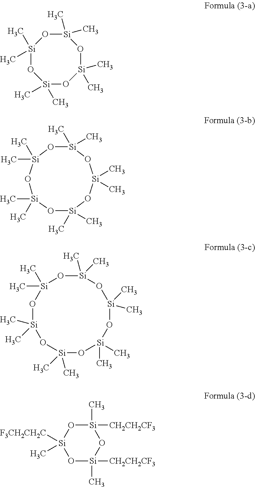
- exemplary silicone oils include cyclosiloxanes having the structure of Formula (3):
- each R g and R h is independently hydrogen, alkyl, aryl, fluoroalkyl, or perfluoroalkyl; and b is an integer from 3 to about 8.
- all of the R g and R h groups are alkyl. In more specific embodiments, they are all alkyl of the same length (i.e. same number of carbon atoms).
- Exemplary compounds of Formula (3) include octamethylcyclotetrasiloxane (aka D4), decamethylcyclopentasiloxane (aka D5), dodecamethylcyclohexasiloxane (aka D6), and 1,3,5-tris[(3,3,3-trifluoropropyl)methyl]cyclotrisiloxane (aka D3F) which are illustrated below as Formulas (3-a), (3-b), (3-c), and (3-d) respectively:
- Other compounds of Formula (3) include hexamethylcyclotrisiloxane (D3) and 1,3,5,7-tetrakis(3,3,3-trifluoropropyl)-1,3,5,7-tetramethylcyclotetrasiloxane (D4F).
- the release oil has a viscosity of 200 centipoise or less and has a boiling point of 150° C. or greater. In more specific embodiments, the release oil has a viscosity of 200 centipoise or less and has a boiling point of 200° C. or greater.
- viscosity data for D3, D3F, and D4F are not available, they are expected to be below 100 centipoise because their apparent viscosities are much lower than silicone oils having viscosities of around 100 centipoise.
- the following table contains some information relating to compounds of Formula (3):
- Lower molecular weight oils can be used with digital offset printing because the transfer temperatures are near room temperature, and so outgassing or vaporization will not occur. The non-reactivity of these oils also permits them to be directly infused into the elastomer before curing without impeding the subsequent curing. Such oils can also diffuse to the surface of the layer with much higher speed (microsecond time scales).
- D4, D5, or D6 can be used as the release oil for silicone elastomers without impeding their cure.
- D3F can be used with fluorosilicone elastomers without impeding their cure either.
- the ink When ink is initially applied to the surface layer, the ink is able to adhere to the elastomer. Then, during transfer, the release oil is released due to pressure applied at the nip. A weak boundary layer film (typically around 10 nm thick) is formed between the surface layer and the ink which is deposited upon the surface layer of the imaging member. This aids in complete transfer of the ink from the imaging member to the receiving substrate (e.g. paper).
- the low molecular weight release oil allows for a lower viscosity boundary layer that promotes cleaner splitting.
- the imaging member surface layer has a low tendency to be penetrated by liquids other than the release oil.
- the ink itself may contain a solvent, and the surface layer desirably resists penetration by such solvents.
- the release oil is usually present in an amount of from about 1 to about 20 weight percent of the surface layer.
- the elastomer may make up from about 80 to about 99 weight percent of the surface layer.
- the silicone rubber may also be loaded with an infrared-absorbing filler that increases energy absorption. This aids in efficient evaporation of the fountain solution.
- the energy is infra-red (IR) energy.
- the metal oxide filler is iron oxide (FeO).
- Other infrared-absorbing fillers include, but are not limited to, carbon black, graphene, graphite, carbon nanotubes, and carbon fibers.
- the metal oxide filler may have an average particle size of from about 2 nanometers to about 10 microns.
- the infrared-absorbing filler may make up from about 5 to about 20 weight percent of the surface layer, including from about 7 to about 15 weight percent.
- the surface layer may also include other fillers, such as silica.
- Silica can help increase the tensile strength of the surface layer and increase wear resistance. Silica may be present in an amount of from about 2 to about 30 weight percent of the surface layer, including from about 5 to about 30 weight percent.
- the surface layer may have a thickness of from about 0.5 microns ( ⁇ m) to about 4 millimeters (mm), depending on the requirements of the overall printing system. It is contemplated that the surface layer is generally homogeneous, though this will change as the surface layer is used and the release oil is consumed during printing.
- the methods may include depositing a surface layer composition upon a mold; and curing the surface layer composition.
- the surface layer composition includes at a minimum the swellable elastomer.
- the surface layer composition may further comprise infrared absorbing filler, silica, a release oil, and/or a catalyst.
- the release oil may be added into the initial surface layer composition or physically absorbed through the surface by wiping or soaking the partially cured or completely cured elastomer layer with the release oil.
- the curing may be performed at room temperature or at a temperature lower than the boiling point of the release oil.
- the processes include applying a fountain solution/dampening fluid to an imaging member comprising an imaging member surface.
- a latent image is formed by evaporating the fountain solution from selective locations on the imaging member surface to form hydrophobic non-image areas and hydrophilic image areas; developing the latent image by applying an ink composition to the hydrophilic image areas; and transferring the developed latent image to a receiving substrate with the application of nip pressure.
- the imaging member surface comprises a swellable elastomer doped with a release oil. The nip pressure results in a layer of the release oil being formed between the surface layer and the developed image to enhance transfer efficiency.
- the present disclosure contemplates a system where the dampening fluid is hydrophobic (i.e. non-aqueous) and the ink somewhat hydrophilic (having a small polar component).
- This system can be used with the imaging member surface layer of the present disclosure.
- the variable lithographic system can be described as comprising an ink composition, a dampening fluid, and an imaging member surface layer, wherein the dampening fluid has a surface energy alpha-beta coordinate which is within the circle connecting the alpha-beta coordinates for the surface energy of the ink and the surface energy of the imaging member surface layer.
- the dampening fluid could remove microscopic background defects (e.g. ⁇ 1 ⁇ m radius) from propagating in subsequent prints.
- the surface may have a roughness of less than 1 ⁇ m when the ink is applied at a thickness of 1 to 2 ⁇ m.
- the dampening fluid does not wet the ink in the presence of air.
- fracture at the exit inking nip should occur where the ink and the dampening fluid interface, not within the dampening fluid itself. This way, dampening fluid will not tend to remain on the imaging member surface after ink has been transferred to a receiving substrate.
- the ink and dampening fluid are chemically immiscible such that only emulsified mixtures can exist. Though the ink and the dampening fluid may have alpha-beta coordinates close together, often choosing the chemistry components with different levels of hydrogen bonding can reduce miscibility by increasing the difference in the Hanson solubility parameters.
- the dampening fluid which is compatible with the ink compositions of the present disclosure is a volatile hydrofluoroether (HFE) liquid or a volatile silicone liquid.
- HFE volatile hydrofluoroether
- silicone liquid a volatile silicone liquid.
- the volatile hydrofluoroether liquid has the structure of Formula (I): C m H p F 2m+1-p —O—C n H q F 2n+1-q Formula (I) wherein m and n are independently integers from 1 to about 9; and p and q are independently integers from 0 to 19.
- the two groups bound to the oxygen atom are alkyl or fluoroalkyl groups.
- Formulas (I-a), (I-b), (I-d), (I-e), (I-f), (I-g), and (I-h) have one alkyl group and one perfluoroalkyl group, either branched or linear. In some terminology, they are also called segregated hydrofluoroethers.
- Formula (I-c) contains two fluoroalkyl groups and is not considered a segregated hydrofluoroether.
- Formula (I-a) is also known as 1,1,1,2,2,3,4,5,5,5-decafluoro-3-methoxy-4-(trifluoromethyl)pentane and has CAS#132182-92-4. It is commercially available as NovecTM 7300.
- Formula (I-b) is also known as 3-ethoxy-1,1,1,2,3,4,4,5,5,6,6,6-dodecafluoro-2-(trifluoromethyl)hexane and has CAS#297730-93-9. It is commercially available as NovecTM 7500.
- Formula (I-c) is also known as 1,1,1,2,3,3-Hexafluoro-4-(1,1,2,3,3,3-hexafluoropropoxy)pentane and has CAS#870778-34-0. It is commercially available as NovecTM 7600.
- Formula (I-f) is also known as 1-methoxyheptafluoropropane or methyl perfluoropropyl ether, and has CAS#375-03-1. It is commercially available as NovecTM 7000.
- Formula (I-g) is also known as ethyl nonafluoroisobutyl ether and has CAS#163702-05-4.
- Formula (I-h) is also known as ethyl nonafluorobutyl ether and has CAS#163702-06-5.
- a mixture of Formulas (I-g) and (I-h) is commercially available as NovecTM 7200 or NovecTM 8200. These two isomers are inseparable and have essentially identical properties.
- heteroaryl refers to a cyclic radical composed of carbon atoms, hydrogen atoms, and a heteroatom within a ring of the radical, the cyclic radical being aromatic.
- the heteroatom may be nitrogen, sulfur, or oxygen.
- exemplary heteroaryl groups include thienyl, pyridinyl, and quinolinyl. When heteroaryl is described in connection with a numerical range of carbon atoms, it should not be construed as including substituted heteroaromatic radicals. Note that heteroaryl groups are not a subset of aryl groups.
- Hexafluoro-m-xylene (HFMX) and hexafluoro-p-xylene (HFPX) are specifically contemplated as being useful compounds of Formula (A) that can be used as low-cost dampening fluids.
- HFMX and HFPX are illustrated below as Formulas (A-a) and (A-b):
- any co-solvent combination of fluorinated damping fluids can be used to help suppress non-desirable characteristics such as a low flammability temperature.
- Exemplary compounds of Formula (II) include hexamethyldisiloxane and octamethyltrisiloxane, which are illustrated below as Formulas (II-a) and (II-b):
- Exemplary compounds of Formula (III) include octamethylcyclotetrasiloxane (aka D4) and decamethylcyclopentasiloxane (aka D5), which are illustrated below as Formulas (III-a) and (III-b):
- An exemplary compound of Formula (IV) is methyl trimethicone, also known as methyltris(trimethylsiloxy)silane, which is commercially available as TMF-1.5 from Shin-Etsu, and shown below with the structure of Formula (IV-a):
- the dampening fluid comprises a mixture of octamethylcyclotetrasiloxane (D4) and decamethylcyclopentasiloxane (D5).
- D4 and D5 are produced by the hydrolysis of the chlorosilanes produced in the Rochow process.
- the ratio of D4 to D5 that is distilled from the hydrolysate reaction is generally about 85% D4 to 15% D5 by weight, and this combination is an azeotrope.
- the dampening fluid comprises a mixture of octamethylcyclotetrasiloxane (D4) and hexamethylcyclotrisiloxane (D3), the D3 being present in an amount of up to 30% by total weight of the D3 and the D4.
- D4 octamethylcyclotetrasiloxane
- D3 hexamethylcyclotrisiloxane
- the effect of this mixture is to lower the effective boiling point for a thin layer of dampening fluid.
- volatile hydrofluoroether liquids and volatile silicone liquids have a low heat of vaporization, low surface tension, and good kinematic viscosity.
- the ink compositions contemplated for use with the present disclosure generally include a colorant and a plurality of selected curable compounds.
- the curable compounds can be cured under ultraviolet (UV) light to fix the ink in place on the final receiving substrate.
- UV ultraviolet
- the term “colorant” includes pigments, dyes, quantum dots, mixtures thereof, and the like. Dyes and pigments have specific advantages. Dyes have good solubility and dispersibility within the ink vehicle. Pigments have excellent thermal and light-fast performance.
- the colorant is present in the ink composition in any desired amount, and is typically present in an amount of from about 10 to about 40 weight percent (wt %), based on the total weight of the ink composition, or from about 20 to about 30 wt %.
- Various pigments and dyes are known in the art, and are commercially available from suppliers such as Clariant, BASF, and Ciba, to name just a few.
- the ink compositions may have a viscosity of from about 5,000 to about 300,000 centipoise at 25° C. and a shear rate of 5 sec ⁇ 1 , including a viscosity of from about 15,000 to about 250,000 cps.
- the ink compositions may have a viscosity of from about 2,000 to about 90,000 centipoise at 25° C. and a shear rate of 50 sec ⁇ 1 , including a viscosity of from about 5,000 to about 65,000 cps.
- the shear thinning index, or SHI is defined in the present disclosure as the ratio of the viscosity of the ink composition at two different shear rates, here 50 sec ⁇ 1 and 5 sec ⁇ 1 .
- the SHI (50/5) may be from about 0.10 to about 0.60 for the ink compositions of the present disclosure, including from about 0.35 to about 0.55.
- These ink compositions may also have a surface tension of at least about 25 dynes/cm at 25° C., including from about 25 dynes/cm to about 40 dynes/cm at 25° C.
- These ink compositions possess many desirable physical and chemical properties. They are compatible with the materials with which they will come into contact, such as the dampening fluid, the surface layer of the imaging member, and the final receiving substrate. They also have the requisite wetting and transfer properties. They can be UV-cured and fixed in place.
- NuSil FS-3502-1A (4.5 g), Halo Carbon 27 (0.6 g), trifluorotoluene (6.0 g), and platinum catalyst (80 microliter, Gelest SIP6831.2 having pt concentration of 2.1-2.4%) was added to a 60 ml polypropylene bottle. The mixture was shaken for at least 30 min before adding the carbon black dispersion (12.0 g), and the resulting mixture was shaken for another 10 min. Nusil hydrofluorosilicone XL150 (0.5 g) was added, all at once, and the resulting mixture was shaken for 10 min and then poured into two polypropylene dishes, each having a diameter of about 2 inches.
- DMS-T21 is a polydimethylsiloxane oil
- PMM-5021 is a phenylmethylsiloxane oil
- FMS-121, -123, -131, and -141 are fluorosilicone oils
- FMS-221 is a 50/50 silicone and fluorosilicone copolymer.
Abstract
Description

where f is the mole percentage of HFP, g is the mole percentage of TFE, h is the mole percentage of VDF, j is the mole percentage of PMVE, and k is the mole percentage of ET; f+g+h+j+k is 100 mole percent; f, g, h, j, and k can individually be zero, but f+g+h+j must be at least 50 mole percent. Please note that Formula (1) only shows the structure of each monomer and their relative amounts, and should not be construed as describing the bonds within the fluoroelastomer (i.e. not as having five blocks). Fluoroelastomers generally have superior chemical resistance and good physical properties. Exemplary fluoroelastomers include those offered under the name VITON by DuPont.

wherein Ra, Rb, Rc, Rd, Re, and Rf are each independently hydrogen, alkyl, fluoroalkyl, or perfluoroalkyl; and a is an integer from 1 to about 5. In some specific embodiments, Ra, Rb, Rc, Rd, Re, and Rf are all alkyl. In more specific embodiments, they are all alkyl of the same length (i.e. same number of carbon atoms such as methyl and ethyl groups).


wherein each Rg and Rh is independently hydrogen, alkyl, aryl, fluoroalkyl, or perfluoroalkyl; and b is an integer from 3 to about 8. In some specific embodiments, all of the Rg and Rh groups are alkyl. In more specific embodiments, they are all alkyl of the same length (i.e. same number of carbon atoms).
| Viscosity | Density | ||||
| Boiling point | (25° C., | (25° C., | |||
| Compound | CAS # | MW | (° C.) | centipoise) | g/cm3) |
| D3 | 541-05-9 | 222.46 | 134 | Solid mp = | 1.02 |
| 65° C. | |||||
| D4 | 556-67-2 | 296.61 | 172-175 | 2.2 | 0.95 |
| D5 | 541-02-6 | 370.77 | 210-211 | 3.5-4 | 0.954 |
| D6 | 540-97-6 | 444.92 | 245 | 6.6 | 0.963 |
| D3F | 2374-14-3 | 468.54 | 239-253 | Solid mp = | 1.23 |
| 34° C. | |||||
| D4F | 429-67-4 | 624.73 | 288 | 1.273 | |
CmHpF2m+1-p—O—CnHqF2n+1-q Formula (I)
wherein m and n are independently integers from 1 to about 9; and p and q are independently integers from 0 to 19. As can be seen, generally the two groups bound to the oxygen atom are alkyl or fluoroalkyl groups.

Ar—(CkF2k+1)t Formula (A)
wherein Ar is an aryl or heteroaryl group; k is an integer from 1 to about 9; and t indicates the number of perfluoroalkyl sidechains, t being from 1 to about 8.

It should be noted any co-solvent combination of fluorinated damping fluids can be used to help suppress non-desirable characteristics such as a low flammability temperature.

wherein Ra, Rb, Rc, Rd, Re, and Rf are each independently hydrogen, alkyl, or perfluoroalkyl; and a is an integer from 1 to about 5. In some specific embodiments, Ra, Rb, Rc, Rd, Re, and Rf are all alkyl. In more specific embodiments, they are all alkyl of the same length (i.e. same number of carbon atoms).


wherein each Rg and Rh is independently hydrogen, alkyl, or perfluoroalkyl; and b is an integer from 3 to about 8. In some specific embodiments, all of the Rg and Rh groups are alkyl. In more specific embodiments, they are all alkyl of the same length (i.e. same number of carbon atoms).


wherein R1, R2, R3, and R4 are independently alkyl or —OSiR1R2R3.

| TABLE 1 | |||||||||
| 1 | 2 | 3 | 4 | 5 | 6 | 7 | 8 | 9 | |
| NuSil | FS-3502-1A | FS-3502-1A | FS-3502-1A | FS-3502-1A | FS-3502-1A | FS-3502-1A | FS-3502-1A | FS-3502-1A | FS-3502-1A |
| Fluorosilicone | |||||||||
| type | |||||||||
| NuSil | 4.50 | 4.80 | 4.50 | 4.50 | 4.50 | 4.50 | 4.50 | 4.50 | 4.53 |
| Fluorosilicone | |||||||||
| (g) | |||||||||
| Oil | Halocarbon | Halocarbon | DMS-T21 | PMM-5021 | FMS-121 | FMS-123 | FMS-221 | FMS-131 | FMS-141 |
| product name | 27 | 27 | |||||||
| Oil | 50 | 50 | 100 | 125 | 80-120 | 300-350 | 80-120 | 1000 | 10000 |
| viscosity@25° C. | |||||||||
| (cSt) | |||||||||
| Oil weight (g) | 0.60 | 0.70 | 0.60 | 0.60 | 0.60 | 0.60 | 0.60 | 0.60 | 0.60 |
| trifluorotoluene | 6.00 | 7.00 | 6.00 | 6.00 | 6.00 | 6.00 | 6.00 | 6.00 | 6.00 |
| (g) | |||||||||
| Pt catalyst (uL) | 80.00 | 70.00 | 80.00 | 80.00 | 80.00 | 80.00 | 80.00 | 80.00 | 80.00 |
| Dispersion of | 12.00 | 13.00 | 14.50 | 14.50 | 14.50 | 14.50 | 14.50 | 14.50 | 14.50 |
| Cabot Vulcan | |||||||||
| XC72 carbon | |||||||||
| black (5 g) in | |||||||||
| trifluorotoluene | |||||||||
| (100 g) | |||||||||
| NuSil XL150 (g) | 0.50 | 1.20 | 1.00 | 1.00 | 1.00 | 1.00 | 1.00 | 1.00 | 1.00 |
| Total Wt | 23.60 | 26.70 | 26.60 | 26.60 | 26.60 | 26.60 | 26.60 | 26.60 | 26.63 |
| Solid Wt | 5.67 | 6.12 | 6.79 | 6.79 | 6.79 | 6.79 | 6.79 | 6.79 | 6.82 |
| solvent WT | 17.93 | 20.58 | 19.81 | 19.81 | 17.93 | 17.93 | 17.93 | 19.81 | 19.81 |
| solvent/solid | 3.16 | 3.36 | 2.92 | 2.92 | 2.64 | 2.64 | 2.64 | 2.92 | 2.90 |
| wt ratio | |||||||||
| C % | 10.08 | 10.12 | 10.17 | 10.17 | 10.17 | 10.17 | 10.17 | 10.17 | 10.12 |
| Oil % | 10.58 | 11.44 | 8.84 | 8.84 | 8.84 | 8.84 | 8.84 | 8.84 | 8.80 |
| deinking | poor | good | poor | fair | excellent | excellent | good | good | fair |
| characteristics | |||||||||
Claims (11)
Priority Applications (1)
| Application Number | Priority Date | Filing Date | Title |
|---|---|---|---|
| US13/601,840 US9956801B2 (en) | 2012-08-31 | 2012-08-31 | Printing plates doped with release oil |
Applications Claiming Priority (1)
| Application Number | Priority Date | Filing Date | Title |
|---|---|---|---|
| US13/601,840 US9956801B2 (en) | 2012-08-31 | 2012-08-31 | Printing plates doped with release oil |
Publications (2)
| Publication Number | Publication Date |
|---|---|
| US20140060358A1 US20140060358A1 (en) | 2014-03-06 |
| US9956801B2 true US9956801B2 (en) | 2018-05-01 |
Family
ID=50185617
Family Applications (1)
| Application Number | Title | Priority Date | Filing Date |
|---|---|---|---|
| US13/601,840 Active 2034-01-17 US9956801B2 (en) | 2012-08-31 | 2012-08-31 | Printing plates doped with release oil |
Country Status (1)
| Country | Link |
|---|---|
| US (1) | US9956801B2 (en) |
Families Citing this family (4)
| Publication number | Priority date | Publication date | Assignee | Title |
|---|---|---|---|---|
| US9950549B2 (en) * | 2016-05-27 | 2018-04-24 | Xerox Corporation | Imaging plate multi-layer blanket |
| US9649834B1 (en) * | 2016-06-25 | 2017-05-16 | Xerox Corporation | Stabilizers against toxic emissions in imaging plate or intermediate blanket materials |
| US10384441B2 (en) * | 2016-07-28 | 2019-08-20 | Xerox Corporation | Fluorosilicone composite and formulation process for imaging plate |
| CN114585490B (en) * | 2019-08-14 | 2023-04-28 | 康宁股份有限公司 | System and method for reducing surface oil streaking on wet extrudates by irradiation |
Citations (55)
| Publication number | Priority date | Publication date | Assignee | Title |
|---|---|---|---|---|
| US3741118A (en) | 1970-06-17 | 1973-06-26 | A Carley | Method for electronic lithography |
| US3800699A (en) | 1970-06-17 | 1974-04-02 | A Carley | Fountain solution image apparatus for electronic lithography |
| US3877372A (en) | 1973-12-03 | 1975-04-15 | Kenneth W Leeds | Treatment of a printing plate with a dampening liquid |
| US4627349A (en) | 1985-05-02 | 1986-12-09 | Claussen Gary J | Heated inking roll for a printer |
| US4887528A (en) | 1988-10-31 | 1989-12-19 | Ceradyne, Inc. | Dampening system roller for offset printing presses |
| US5067404A (en) | 1988-02-26 | 1991-11-26 | Siemens Aktiengesellschaft | Method and apparatus for printing by inking a latent thermal image |
| JPH0682213B2 (en) * | 1986-06-16 | 1994-10-19 | 東レ株式会社 | Waterless planographic printing plate |
| US5366772A (en) * | 1993-07-28 | 1994-11-22 | Xerox Corporation | Fuser member |
| US5701815A (en) | 1993-11-03 | 1997-12-30 | Corning Incorporated | Method of printing a color filter |
| US5763129A (en) * | 1995-08-01 | 1998-06-09 | Eastman Kodak Company | Method of increasing gloss and transparency clarity of fused toner images |
| US5855173A (en) | 1995-10-20 | 1999-01-05 | Eastman Kodak Company | Zirconia alloy cylinders and sleeves for imaging and lithographic printing methods |
| US6125756A (en) | 1994-07-22 | 2000-10-03 | Man Roland Druckmaschinen Ag | Erasable printing plate having a smooth pore free ceramic or glass surface |
| US6146798A (en) | 1998-12-30 | 2000-11-14 | Xerox Corporation | Printing plate with reversible charge-controlled wetting |
| US6261688B1 (en) * | 1999-08-20 | 2001-07-17 | Xerox Corporation | Tertiary amine functionalized fuser fluids |
| US6318264B1 (en) | 1998-06-12 | 2001-11-20 | Heidelberger Druckmaschinen Ag | Printing machine and printing process |
| DE10160734A1 (en) | 2001-01-11 | 2002-07-18 | Heidelberger Druckmasch Ag | Printer having continuous type short inking unit suitable for print runs where on average only a small part of the surface area is to be coated in ink |
| US20030167950A1 (en) | 2002-02-12 | 2003-09-11 | Takahiro Mori | Printing plate precursor and printing plate |
| US20040011234A1 (en) | 2000-09-28 | 2004-01-22 | Murray Figov | Method of printing variable information |
| US6725777B2 (en) | 2001-03-22 | 2004-04-27 | Ricoh Company Ltd. | Recording medium with dispersed ink adhering and ink releasing materials |
| DE10360108A1 (en) | 2003-03-22 | 2004-10-07 | Heidelberger Druckmaschinen Ag | Printing plate, for the printing cylinder of an offset printing press has a surface of a shape memory material which is subjected to two different temperatures to give an erasure for repeated use |
| US6841366B1 (en) | 1993-06-25 | 2005-01-11 | Dsm Ip Assets B.V. | Biotin biosynthesis in bacillus subtilis |
| US20050178281A1 (en) | 2002-02-19 | 2005-08-18 | Martin Berg | Printing device and method, in which a humidity promoter is applied prior to the ink-repellent or ink-receptive layer |
| US20050258136A1 (en) | 2004-05-21 | 2005-11-24 | Fuji Photo Film Co., Ltd. | Method for providing surface texturing of aluminum sheet, substrate for lithographic plate and lithographic plate |
| US7020355B2 (en) | 2001-11-02 | 2006-03-28 | Massachusetts Institute Of Technology | Switchable surfaces |
| US7061513B2 (en) | 1999-03-02 | 2006-06-13 | Ricoh Company, Ltd. | Image recording body and image forming apparatus by use of the same |
| US20060152566A1 (en) | 2003-06-23 | 2006-07-13 | Hiroshi Taniuchi | Image forming method, image formng apparatus, intermediate transfer body, method of modifying surface of intermediate transfer body |
| US7100503B2 (en) | 2001-07-03 | 2006-09-05 | Oce Printing Systems Gmbh | Method and device for producing different printed images on the same print substrate |
| WO2006133024A2 (en) | 2005-06-06 | 2006-12-14 | Seratek, Llc. | Method and apparatus for a tape-rewinding substrate cleaner |
| US20070199461A1 (en) | 2006-02-21 | 2007-08-30 | Cyman Theodore F Jr | Systems and methods for high speed variable printing |
| US20080011177A1 (en) | 2004-08-04 | 2008-01-17 | Shuhou Co., Ltd. | Method of Printing Curved Surface and Curved Surface Body Printed by Using Same |
| US20080032072A1 (en) | 2006-06-15 | 2008-02-07 | Canon Kabushiki Kaisha | Method of producing recorded product (printed product) and image forming apparatus |
| DE102006050744A1 (en) | 2006-10-27 | 2008-04-30 | Koenig & Bauer Aktiengesellschaft | Device for tempering of inking rollers in printing machine, has lateral surface of inking roller, where lateral surface is assigned to heating device, controlled by controlling device, and cooling device is assigned to inking roller |
| EP1935640A2 (en) | 2006-12-19 | 2008-06-25 | Palo Alto Research Center Incorporated | Printing plate and system using heat-decomposable polymers |
| EP1938987A2 (en) | 2006-12-22 | 2008-07-02 | MAN Roland Druckmaschinen AG | Device for controlling the ink transport in an inking unit |
| EP1964678A2 (en) | 2007-02-27 | 2008-09-03 | Mitsubishi Heavy Industries, Ltd. | Printing method and printing press |
| US20080223240A1 (en) | 2005-09-02 | 2008-09-18 | Xaar Technology Limited | Method of Printing |
| WO2009025821A1 (en) | 2007-08-20 | 2009-02-26 | Rr Donnelley | Apparatus and methods for controlling application of a substance to a substrate |
| JP2009184275A (en) * | 2008-02-08 | 2009-08-20 | Hitachi Chem Co Ltd | Micro-fine resin structure, and production method therefor |
| US20100031838A1 (en) | 2008-08-06 | 2010-02-11 | Lewis Thomas E | Plateless lithographic printing |
| DE102008062741A1 (en) | 2008-12-17 | 2010-07-01 | Industrie-Automation Vertriebs-Gmbh | Method for dosing e.g. printing ink in printing machine to coat printing material with ink, involves evaluating signals of two temperature sensors by controller such that delay time difference between signals is determined |
| US20120103221A1 (en) | 2010-10-29 | 2012-05-03 | Palo Alto Research Center Incorporated | Cleaning Method for a Variable Data Lithography System |
| US20120103219A1 (en) | 2010-10-29 | 2012-05-03 | Palo Alto Research Center Incorporated | Ink Transfer Subsystem for a Variable Data Lithography System |
| US20120103217A1 (en) | 2010-10-29 | 2012-05-03 | Palo Alto Research Center Incorporated | Cleaning Subsystem for a Variable Data Lithography System |
| US20120103212A1 (en) | 2010-10-29 | 2012-05-03 | Palo Alto Research Center Incorporated | Variable Data Lithography System |
| US20120103218A1 (en) | 2010-10-29 | 2012-05-03 | Palo Alto Research Center Incorporated | Method of Ink Rheology Control in a Variable Data Lithography System |
| US20120103214A1 (en) | 2010-10-29 | 2012-05-03 | Palo Alto Research Center Incorporated | Heated Inking Roller for a Variable Data Lithography System |
| US20120103213A1 (en) | 2010-10-29 | 2012-05-03 | Palo Alto Research Center Incorporated | Ink Rheology Control Subsystem for a Variable Data Lithography System |
| US20120274914A1 (en) | 2011-04-27 | 2012-11-01 | Palo Alto Research Center Incorporated | Variable Data Lithography System for Applying Multi-Component Images and Systems Therefor |
| US8347787B1 (en) | 2011-08-05 | 2013-01-08 | Palo Alto Research Center Incorporated | Variable data lithography apparatus employing a thermal printhead subsystem |
| US20130033687A1 (en) | 2011-08-05 | 2013-02-07 | Palo Alto Research Center Incorporated | Method for Direct Application of Dampening Fluid for a Variable Data Lithographic Apparatus |
| US20130033688A1 (en) | 2011-04-27 | 2013-02-07 | Palo Alto Research Center Incorporated | System for Direct Application of Dampening Fluid for a Variable Data Lithographic Apparatus |
| US20130033686A1 (en) | 2011-08-05 | 2013-02-07 | Palo Alto Research Center Incorporated | Direct Application of Dampening Fluid for a Variable Data Lithographic Apparatus |
| US20130032050A1 (en) | 2011-04-27 | 2013-02-07 | Xerox Corporation | Environmental Control Subsystem for a Variable Data Lithographic Apparatus |
| US8919252B2 (en) * | 2012-08-31 | 2014-12-30 | Xerox Corporation | Methods and systems for ink-based digital printing with multi-component, multi-functional fountain solution |
| US8943961B2 (en) * | 2012-07-10 | 2015-02-03 | Xerox Corporation | Systems and methods for facilitating oil delivery in digital offset lithographic printing techniques |
-
2012
- 2012-08-31 US US13/601,840 patent/US9956801B2/en active Active
Patent Citations (61)
| Publication number | Priority date | Publication date | Assignee | Title |
|---|---|---|---|---|
| US3741118A (en) | 1970-06-17 | 1973-06-26 | A Carley | Method for electronic lithography |
| US3800699A (en) | 1970-06-17 | 1974-04-02 | A Carley | Fountain solution image apparatus for electronic lithography |
| US3877372A (en) | 1973-12-03 | 1975-04-15 | Kenneth W Leeds | Treatment of a printing plate with a dampening liquid |
| US4627349A (en) | 1985-05-02 | 1986-12-09 | Claussen Gary J | Heated inking roll for a printer |
| JPH0682213B2 (en) * | 1986-06-16 | 1994-10-19 | 東レ株式会社 | Waterless planographic printing plate |
| US5067404A (en) | 1988-02-26 | 1991-11-26 | Siemens Aktiengesellschaft | Method and apparatus for printing by inking a latent thermal image |
| US4887528A (en) | 1988-10-31 | 1989-12-19 | Ceradyne, Inc. | Dampening system roller for offset printing presses |
| US6841366B1 (en) | 1993-06-25 | 2005-01-11 | Dsm Ip Assets B.V. | Biotin biosynthesis in bacillus subtilis |
| US5366772A (en) * | 1993-07-28 | 1994-11-22 | Xerox Corporation | Fuser member |
| US5701815A (en) | 1993-11-03 | 1997-12-30 | Corning Incorporated | Method of printing a color filter |
| US6125756A (en) | 1994-07-22 | 2000-10-03 | Man Roland Druckmaschinen Ag | Erasable printing plate having a smooth pore free ceramic or glass surface |
| US5763129A (en) * | 1995-08-01 | 1998-06-09 | Eastman Kodak Company | Method of increasing gloss and transparency clarity of fused toner images |
| US5855173A (en) | 1995-10-20 | 1999-01-05 | Eastman Kodak Company | Zirconia alloy cylinders and sleeves for imaging and lithographic printing methods |
| US6318264B1 (en) | 1998-06-12 | 2001-11-20 | Heidelberger Druckmaschinen Ag | Printing machine and printing process |
| US6146798A (en) | 1998-12-30 | 2000-11-14 | Xerox Corporation | Printing plate with reversible charge-controlled wetting |
| US7061513B2 (en) | 1999-03-02 | 2006-06-13 | Ricoh Company, Ltd. | Image recording body and image forming apparatus by use of the same |
| US6261688B1 (en) * | 1999-08-20 | 2001-07-17 | Xerox Corporation | Tertiary amine functionalized fuser fluids |
| US20040011234A1 (en) | 2000-09-28 | 2004-01-22 | Murray Figov | Method of printing variable information |
| DE10160734A1 (en) | 2001-01-11 | 2002-07-18 | Heidelberger Druckmasch Ag | Printer having continuous type short inking unit suitable for print runs where on average only a small part of the surface area is to be coated in ink |
| US6725777B2 (en) | 2001-03-22 | 2004-04-27 | Ricoh Company Ltd. | Recording medium with dispersed ink adhering and ink releasing materials |
| US7100503B2 (en) | 2001-07-03 | 2006-09-05 | Oce Printing Systems Gmbh | Method and device for producing different printed images on the same print substrate |
| US7020355B2 (en) | 2001-11-02 | 2006-03-28 | Massachusetts Institute Of Technology | Switchable surfaces |
| US20030167950A1 (en) | 2002-02-12 | 2003-09-11 | Takahiro Mori | Printing plate precursor and printing plate |
| US20050178281A1 (en) | 2002-02-19 | 2005-08-18 | Martin Berg | Printing device and method, in which a humidity promoter is applied prior to the ink-repellent or ink-receptive layer |
| US7191705B2 (en) | 2002-02-19 | 2007-03-20 | Oce Printing Systems Gmbh | Printing device and method, in which a humidity promoter is applied prior to the ink-repellent or ink-receptive layer |
| DE10360108A1 (en) | 2003-03-22 | 2004-10-07 | Heidelberger Druckmaschinen Ag | Printing plate, for the printing cylinder of an offset printing press has a surface of a shape memory material which is subjected to two different temperatures to give an erasure for repeated use |
| US20060152566A1 (en) | 2003-06-23 | 2006-07-13 | Hiroshi Taniuchi | Image forming method, image formng apparatus, intermediate transfer body, method of modifying surface of intermediate transfer body |
| US20050258136A1 (en) | 2004-05-21 | 2005-11-24 | Fuji Photo Film Co., Ltd. | Method for providing surface texturing of aluminum sheet, substrate for lithographic plate and lithographic plate |
| US20080011177A1 (en) | 2004-08-04 | 2008-01-17 | Shuhou Co., Ltd. | Method of Printing Curved Surface and Curved Surface Body Printed by Using Same |
| WO2006133024A2 (en) | 2005-06-06 | 2006-12-14 | Seratek, Llc. | Method and apparatus for a tape-rewinding substrate cleaner |
| US20080223240A1 (en) | 2005-09-02 | 2008-09-18 | Xaar Technology Limited | Method of Printing |
| US20070199459A1 (en) | 2006-02-21 | 2007-08-30 | Cyman Theodore F Jr | Systems and methods for high speed variable printing |
| US20070199461A1 (en) | 2006-02-21 | 2007-08-30 | Cyman Theodore F Jr | Systems and methods for high speed variable printing |
| US20070199458A1 (en) | 2006-02-21 | 2007-08-30 | Cyman Theodore F Jr | Systems and methods for high speed variable printing |
| US20070199462A1 (en) | 2006-02-21 | 2007-08-30 | Cyman Theodore F Jr | Systems and methods for high speed variable printing |
| US20070199457A1 (en) | 2006-02-21 | 2007-08-30 | Cyman Theodore F Jr | Systems and methods for high speed variable printing |
| US20070199460A1 (en) | 2006-02-21 | 2007-08-30 | Cyman Theodore F Jr | Systems and methods for high speed variable printing |
| US20080032072A1 (en) | 2006-06-15 | 2008-02-07 | Canon Kabushiki Kaisha | Method of producing recorded product (printed product) and image forming apparatus |
| DE102006050744A1 (en) | 2006-10-27 | 2008-04-30 | Koenig & Bauer Aktiengesellschaft | Device for tempering of inking rollers in printing machine, has lateral surface of inking roller, where lateral surface is assigned to heating device, controlled by controlling device, and cooling device is assigned to inking roller |
| EP1935640A2 (en) | 2006-12-19 | 2008-06-25 | Palo Alto Research Center Incorporated | Printing plate and system using heat-decomposable polymers |
| EP1938987A2 (en) | 2006-12-22 | 2008-07-02 | MAN Roland Druckmaschinen AG | Device for controlling the ink transport in an inking unit |
| EP1964678A2 (en) | 2007-02-27 | 2008-09-03 | Mitsubishi Heavy Industries, Ltd. | Printing method and printing press |
| WO2009025821A1 (en) | 2007-08-20 | 2009-02-26 | Rr Donnelley | Apparatus and methods for controlling application of a substance to a substrate |
| JP2009184275A (en) * | 2008-02-08 | 2009-08-20 | Hitachi Chem Co Ltd | Micro-fine resin structure, and production method therefor |
| US20100031838A1 (en) | 2008-08-06 | 2010-02-11 | Lewis Thomas E | Plateless lithographic printing |
| DE102008062741A1 (en) | 2008-12-17 | 2010-07-01 | Industrie-Automation Vertriebs-Gmbh | Method for dosing e.g. printing ink in printing machine to coat printing material with ink, involves evaluating signals of two temperature sensors by controller such that delay time difference between signals is determined |
| US20120103221A1 (en) | 2010-10-29 | 2012-05-03 | Palo Alto Research Center Incorporated | Cleaning Method for a Variable Data Lithography System |
| US20120103219A1 (en) | 2010-10-29 | 2012-05-03 | Palo Alto Research Center Incorporated | Ink Transfer Subsystem for a Variable Data Lithography System |
| US20120103217A1 (en) | 2010-10-29 | 2012-05-03 | Palo Alto Research Center Incorporated | Cleaning Subsystem for a Variable Data Lithography System |
| US20120103212A1 (en) | 2010-10-29 | 2012-05-03 | Palo Alto Research Center Incorporated | Variable Data Lithography System |
| US20120103218A1 (en) | 2010-10-29 | 2012-05-03 | Palo Alto Research Center Incorporated | Method of Ink Rheology Control in a Variable Data Lithography System |
| US20120103214A1 (en) | 2010-10-29 | 2012-05-03 | Palo Alto Research Center Incorporated | Heated Inking Roller for a Variable Data Lithography System |
| US20120103213A1 (en) | 2010-10-29 | 2012-05-03 | Palo Alto Research Center Incorporated | Ink Rheology Control Subsystem for a Variable Data Lithography System |
| US20120274914A1 (en) | 2011-04-27 | 2012-11-01 | Palo Alto Research Center Incorporated | Variable Data Lithography System for Applying Multi-Component Images and Systems Therefor |
| US20130033688A1 (en) | 2011-04-27 | 2013-02-07 | Palo Alto Research Center Incorporated | System for Direct Application of Dampening Fluid for a Variable Data Lithographic Apparatus |
| US20130032050A1 (en) | 2011-04-27 | 2013-02-07 | Xerox Corporation | Environmental Control Subsystem for a Variable Data Lithographic Apparatus |
| US8347787B1 (en) | 2011-08-05 | 2013-01-08 | Palo Alto Research Center Incorporated | Variable data lithography apparatus employing a thermal printhead subsystem |
| US20130033687A1 (en) | 2011-08-05 | 2013-02-07 | Palo Alto Research Center Incorporated | Method for Direct Application of Dampening Fluid for a Variable Data Lithographic Apparatus |
| US20130033686A1 (en) | 2011-08-05 | 2013-02-07 | Palo Alto Research Center Incorporated | Direct Application of Dampening Fluid for a Variable Data Lithographic Apparatus |
| US8943961B2 (en) * | 2012-07-10 | 2015-02-03 | Xerox Corporation | Systems and methods for facilitating oil delivery in digital offset lithographic printing techniques |
| US8919252B2 (en) * | 2012-08-31 | 2014-12-30 | Xerox Corporation | Methods and systems for ink-based digital printing with multi-component, multi-functional fountain solution |
Non-Patent Citations (22)
| Title |
|---|
| Biegelsen, U.S. Appl. No. 13/366,947, filed Feb. 6, 2012. |
| European Search Report in corresponding related application EP 11 187 189.3 dated Feb. 28, 2012. |
| European Search Report in corresponding related application EP 11 187 190.1 dated Mar. 12, 2012. |
| European Search Report in corresponding related application EP 11 187 191.9 dated Mar. 1, 2012. |
| European Search Report in corresponding related application EP 11 187 192.7 dated Feb. 28, 2012. |
| European Search Report in corresponding related application EP 11 187 193.5 dated Feb. 29, 2012. |
| European Search Report in corresponding related application EP 11 187 195.0 dated Mar. 28, 2012. |
| European Search Report in corresponding related application EP 11 187 196.8 dated Mar. 30, 2012. |
| Gervasi et al., U.S. Appl. No. 13/601,920, filed Aug. 31, 2012. |
| Gervasi et al., U.S. Appl. No. 13/601,938, filed Aug. 31, 2012. |
| Gervasi et al., U.S. Appl. No. 13/601,956, filed Aug. 31, 2012. |
| Hsieh, U.S. Appl. No. 13/601,817, filed Aug. 31, 2012. |
| Kanungo et al., U.S. Appl. No. 13/601,892, filed Aug. 31, 2012. |
| Kanungo et al., U.S. Appl. No. 13/601,962, filed Aug. 31, 2012. |
| Katano et al., "The New Printing System Using the Materials of Reversible Change of Wettability", International Congress of Imaging Science 2002, Tokyo, pp. 297 et seq. (2002). |
| Kelly et al., U.S. Appl. No. 13/601,854, filed Aug. 31, 2012. |
| Lestrange et al., U.S. Appl. No. 13/601,803, filed Aug. 31, 2012. |
| Liu et al., U.S. Appl. No. 13/426,209, filed Mar. 21, 2012. |
| Liu et al., U.S. Appl. No. 13/426,262, filed Mar. 21, 2012. |
| Liu, U.S. Appl. No. 13/601,876, filed Aug. 31, 2012. |
| Moorlag et al., U.S. Appl. No 13/601,905, filed Aug. 31, 2012. |
| Shen et al., "A new understanding on the mechanism of fountain solution in the prevention of ink transfer to the non-image area in conventional offset lithography", J. Adhesion Sci. Technol., vol. 18, No. 15-16, pp. 1861-1887 (2004). |
Also Published As
| Publication number | Publication date |
|---|---|
| US20140060358A1 (en) | 2014-03-06 |
Similar Documents
| Publication | Publication Date | Title |
|---|---|---|
| US9592698B2 (en) | Imaging member for offset printing applications | |
| US9616654B2 (en) | Imaging member for offset printing applications | |
| US9561677B2 (en) | Imaging member for offset printing applications | |
| US9567486B2 (en) | Imaging member for offset printing applications | |
| US20140060363A1 (en) | Imaging member for offset printing applications | |
| US20140060357A1 (en) | Imaging member | |
| US9283795B1 (en) | Imaging member for offset printing applications | |
| US9592699B2 (en) | Dampening fluid for digital lithographic printing | |
| US20140060360A1 (en) | Textured imaging member | |
| US9649834B1 (en) | Stabilizers against toxic emissions in imaging plate or intermediate blanket materials | |
| US9724909B2 (en) | Methods for ink-based digital printing with high ink transfer efficiency | |
| JP6081284B2 (en) | Process for variable lithographic printing | |
| US9011594B1 (en) | Methods for forming functionalized carbon black with amino-terminated polyfluorodimethylsiloxane for printing | |
| US9327487B2 (en) | Variable lithographic printing process | |
| US9956801B2 (en) | Printing plates doped with release oil | |
| US10384441B2 (en) | Fluorosilicone composite and formulation process for imaging plate | |
| US20140060362A1 (en) | Imaging member for offset printing applications | |
| EP2586622A2 (en) | Dampening Fluid for Digital Lithographic Printing | |
| US9630423B2 (en) | Hydrophilic imaging member surface material for variable data ink-based digital printing systems and methods for manufacturing hydrophilic imaging member surface materials |
Legal Events
| Date | Code | Title | Description |
|---|---|---|---|
| AS | Assignment |
Owner name: XEROX CORPORATION, CONNECTICUT Free format text: ASSIGNMENT OF ASSIGNORS INTEREST;ASSIGNORS:BADESHA, SANTOKH S.;LIU, CHU-HENG;KANUNGO, MANDAKINI;AND OTHERS;SIGNING DATES FROM 20120828 TO 20120829;REEL/FRAME:029124/0349 Owner name: PALO ALTO RESEARCH CENTER INCORPORATED, CALIFORNIA Free format text: ASSIGNMENT OF ASSIGNORS INTEREST;ASSIGNORS:BADESHA, SANTOKH S.;LIU, CHU-HENG;KANUNGO, MANDAKINI;AND OTHERS;SIGNING DATES FROM 20120828 TO 20120829;REEL/FRAME:029124/0349 |
|
| AS | Assignment |
Owner name: XEROX CORPORATION, CONNECTICUT Free format text: ASSIGNMENT OF ASSIGNORS INTEREST;ASSIGNOR:RAMESH, PALGHAT SRINIVAS;REEL/FRAME:031100/0944 Effective date: 20130820 |
|
| STCF | Information on status: patent grant |
Free format text: PATENTED CASE |
|
| MAFP | Maintenance fee payment |
Free format text: PAYMENT OF MAINTENANCE FEE, 4TH YEAR, LARGE ENTITY (ORIGINAL EVENT CODE: M1551); ENTITY STATUS OF PATENT OWNER: LARGE ENTITY Year of fee payment: 4 |
|
| AS | Assignment |
Owner name: XEROX CORPORATION, CONNECTICUT Free format text: ASSIGNMENT OF ASSIGNORS INTEREST;ASSIGNOR:PALO ALTO RESEARCH CENTER INCORPORATED;REEL/FRAME:064038/0001 Effective date: 20230416 |
|
| AS | Assignment |
Owner name: CITIBANK, N.A., AS COLLATERAL AGENT, NEW YORK Free format text: SECURITY INTEREST;ASSIGNOR:XEROX CORPORATION;REEL/FRAME:064760/0389 Effective date: 20230621 |
|
| AS | Assignment |
Owner name: XEROX CORPORATION, CONNECTICUT Free format text: CORRECTIVE ASSIGNMENT TO CORRECT THE REMOVAL OF US PATENTS 9356603, 10026651, 10626048 AND INCLUSION OF US PATENT 7167871 PREVIOUSLY RECORDED ON REEL 064038 FRAME 0001. ASSIGNOR(S) HEREBY CONFIRMS THE ASSIGNMENT;ASSIGNOR:PALO ALTO RESEARCH CENTER INCORPORATED;REEL/FRAME:064161/0001 Effective date: 20230416 |
|
| AS | Assignment |
Owner name: JEFFERIES FINANCE LLC, AS COLLATERAL AGENT, NEW YORK Free format text: SECURITY INTEREST;ASSIGNOR:XEROX CORPORATION;REEL/FRAME:065628/0019 Effective date: 20231117 |
|
| AS | Assignment |
Owner name: CITIBANK, N.A., AS COLLATERAL AGENT, NEW YORK Free format text: SECURITY INTEREST;ASSIGNOR:XEROX CORPORATION;REEL/FRAME:066741/0001 Effective date: 20240206 |