BACKGROUND OF THE INVENTION
-
This invention relates to a medical image processing
system, medical image pickup system and a method of
administrating medical images.
-
In recent years, it is actualized in hospitals that a
plurality of input apparatus such as an image pickup
apparatus such as a CT (Computed Tomography) apparatus and an
MRI (Magnetic Resonance Imaging) apparatus and reading
apparatus such as a CR (Computed Radiography) apparatus and
an FPD (Flat panel Display) apparatus are connected with a
network, while output apparatus such as an imager and a
viewer are also connected with a network. Further, it is put
into practice that image information of a patient inputted by
means of an input apparatus that is most convenient in terms
of operation flow (for example, an input apparatus located
near a person who is in charge of the input such as a
radiographer who inputs image information of a patient) is
outputted by means of an output apparatus that is most
convenient in terms of operation flow (for example, an output
apparatus located near a doctor who carries out diagnosis of
a patient by using said image information), and the overall
efficiency of diagnosis is made higher (refer to the patent
literature 1, for example).
-
Further, in cases where a plurality of doctors diagnose
one and the same patient, sometimes image information of the
patient is distributed to a plurality of output apparatus.
[Patent literature 1]
-
The publication of the unexamined patent application
2002-159476.
-
Further, a radiation image pickup apparatus is one that
uses a medical image conversion panel having a stimulable
phosphor layer formed on a substrate, and a latent image is
formed by the following process: that is, radiation
transmitted through a radiographic object is absorbed by the
stimulable phosphor layer of this conversion panel, in which
radiation energy corresponding to the radiation transmittance
of various parts of the radiographic object is accumulated.
After that, by excitation light rays such as infrared rays
scanning this phosphor layer, the accumulated radiation
energy is made to emit fluorescent light, which is converted
into electricity, to give a medical image signal. A medical
image obtained in this way, having been subjected to image
processing, is outputted to a film or an output device such
as a CRT to become visualized, or preserved in a filing
device such as a server together with some bits of
information of the patient, to be utilized in medical
activity.
-
As regards a medical image radiographing system
utilizing an image pickup apparatus as described above, the
system structure employed is generally classified into two.
One is a conventional medical image system in which an
apparatus for picking up and reading an image and a
stimulable phosphor plate are arranged in or in the
neighborhood of an image pickup room, and the image pickup is
carried out in the image pickup room. In this system, it is
possible to carry out the reading of an image at the same
time of the pickup of the image in the image pickup room.
-
The other is a medical image system in which
radiographing is carried out in the field of the round of
visits of a doctor, for patients who cannot be subjected to
radiographing in an image pickup room such as a patient of a
broken bone or of a disease of cerebral veins or patients
under control in a centralized treatment room, by the
utilization of a movable image pickup apparatus for round of
visits and a portable cassette with a built-in stimulable
phosphor plate (refer to the patent literature 2, for
example). In this system, the reading of an image is carried
out through the insertion of the cassette into a reading
device dedicated to a cassette after the image pickup.
-
In such a medical image pickup system, as described
above, a plurality of apparatus such as an image pickup
apparatus and image reading apparatus installed in an image
pickup room, a movable image pickup apparatus, and a reading
apparatus dedicated to a cassette are utilized. Therefore,
in order that a medical image of the same image quality can
be provided, even in the case where different image pickup
apparatus and reading apparatus are utilized, information
which is necessary for image processing is added to the
radiographed image data as attached bits of information
(refer to the patent literature 3, for example). In another
way, it is known a medical information administration
apparatus capable of editing the attached bits of information
to be added to image data in order to make such a system be
capable of extension (refer to the patent literature 4, for
example).
[Patent literature 2]
-
The publication of the unexamined patent application
2000-139885.
[Patent literature 3]
-
The publication of the unexamined patent application
S62-150474.
[Patent literature 4]
-
The publication of the unexamined patent application
2002-133394.
(PROBLEM TO BE SOLVED BY THE INVENTION)
-
Now, as regards input apparatus, it has been actualized
that what is called a decentralized processing system in
which a plurality of cassettes (plates) are made to be used
in a plurality of reading apparatus in a computed radiography
apparatus for example, and an FPD integrally made of both
cassette and reading apparatus also has come to be used. In
this way, the route for supplying a diagnosis image to an
output apparatus, the combination of apparatus to be used,
etc. have become complex.
-
Further, it cannot be said that the same image
information is obtained by all of these various kinds of
apparatus used, but for example, the image information is
subject to the influence of the deterioration of the function
of the apparatus accompanied by its being used and to the
influence of the environment (dusts etc.).
-
In this way, at the sending-out side of diagnosis
information (input apparatus), in cases where some failure
occurs in diagnosis information accompanied by the
decentralized arrangement of the apparatus with the work flow
in the hospital taken into consideration, the specification
of the cause has come to be a difficult operation requiring a
considerably long time.
-
On the other hand, as regards the output apparatus, for
example, there is an imager of a type in which a full-frame
image on a film can be obtained by a main scanning using a
polygonal mirror and a sub-scanning caused by film
conveyance; however, sometimes there is a difference in the
performance between one and another of the apparatus, and for
example, sometimes the finished images do not become quite
the same even if the same data are visualized by the imagers
due to the difference of the beam diameter in the main
scanning or the unevenness of feed in the sub-scanning.
-
That is, if the number of imager used is one, the same
images are easy to obtain from the same data, which gives
comparatively a little influence to diagnosis; however, if a
plurality of imagers are used, due to the difference of the
performance among the apparatus, there is a possibility of
images being in different states even from the same data,
which gives some apprehension about the influence to
diagnosis. In particular, in such a case that the states of
cure of a focus of the same patient changing with the passage
of time are compared, and in the case where an image
radiographed this time is compared with the image of one
month before and with the image of two months before, if the
image is outputted by means of a different imager from the
others this time only, it sometimes occurs that the state of
the image become different from the others (for example, the
state of image becomes inferior to the other images) owing to
the difference in the performance between the imagers, and it
can be considered that the diagnosis by the image become
erroneous because of this point.
-
Further, also in cases where a failure is generated in
the imager owing to an insufficient maintenance of the
imager, no version upgrading having been carried out for the
control software of the imager, or the like, sometimes the
state of the image become different from the others.
-
In such cases, on the basis of the observation such
that the patient is properly to be getting better, the output
to a film is done over again on the basis of existing data,
or the output is done over again from the image input, and
the pursuit of the cause is to be carried out; this has been
an operation requiring a considerable amount of time and
number of working hours, and exhausting large amount of
resources.
-
Besides, in cases where a plurality of imagers are
arranged in accordance with the work flow in the hospital in
the same way as the case of the input apparatus, or in the
case where these imagers make backup mutually to become
complementary to one another, the pursuit of the cause of
failures in the case where an extensive view of the whole
from the input to the output is taken becomes further more
difficult.
-
Incidentally, because a plurality of apparatus are
utilized in a conventional medical image pickup system as
described in the above, in cases where an abnormality is
generated in a radiographed medical image, it has been
difficult to identify in which process the abnormality is
generated among a sequence of radiographing processes. That
is, in a conventional medical image pickup system,
supplementary information attached to image data has been
information to be added for the purpose of forming a high-quality
image, and it has not been the information to be
utilized for the pursuit of cause of an abnormality being
generated.
-
Further, the cause of an abnormality being generated is
not only a failure in the apparatus such as the image pickup
apparatus and the reading apparatus, but also in the case
where a medical image pickup system for carrying out the
radiographing at a site of round of visits, sometimes the
radiographing environment at the site of round of visits, the
cassette used, etc. In another case, sometimes the cause of
an abnormality being generated is the technical level of the
radiographer carrying out the image pickup.
-
It is an object of this invention to provide a medical
image pickup system and a method of controlling medical
images which make it possible, in cases where an abnormality
is generated in a medical image, to identify the cause of the
abnormality being produced easily and speedily, to remove the
abnormality quickly.
SUMMARY OF THE INVENTION
-
The above-mentioned problems can be solved by an
invention having any one of the features described below.
- (1) A medical image processing system equipped with
an input section for inputting image information of a
patient, and
an output section for visualizing image information of
a patient inputted from said input section, characterized by
being further equipped with
an input information recording section (image-attached
information recording section) capable of recording, as
information attached to image information, at least one of
input section information on the input section which
has been used in the inputting of image information, and
information of the cassette which has been loaded in
said input section and used in the inputting of image
information or on the stimulable phosphor sheet loaded in the
cassette.
According to the invention having the feature described
in (1), at least one of input section information enabling
the identification of the input section (reader) used in the
inputting, and cassette information enabling the
identification of the cassette loaded in said input section
and used in the inputting of image information or the
stimulable phosphor sheet accommodated in the cassette is
made to be recorded; therefore, in cases where a failure of
image information is generated, it can be immediately judged
whether or not the cause is in the input section and/or in
the cassette by the mere confirmation of the input section
and/or the cassette concerned. - (2) A medical image processing system having a feature
as set forth in the feature (1), characterized by
being further equipped with an image information
confirming section for displaying to confirm image
information inputted from the aforesaid input section, and
being capable of recording information indicating the
existence of a defect as information attached to image
information, in cases where a defect of image information is
discovered at the time of confirmation of image information
in said image information confirming section.
According to the feature (2), the medical image
processing system is equipped with an image information
confirming section for displaying to confirm image
information such as a viewer, and is capable of recording
information indicating the existence of a defect as
information attached to image information, in cases where the
existence of a defect in image information is discovered by
the display for confirmation (for example, disturbance in
image information due to dusts etc.); therefore,
discrimination between normal image information and defective
image information can be easily made, and after that, the
pursuit of the cause of the failure can be quickly carried
out. - (3) A medical image processing system having a feature
as set forth in the feature (2), characterized by being
further equipped with
an image saving section for storing and saving image
information and image-attached information inputted,
a defect information detecting section for detecting
information indicating the existence of a defect from the
image-attached information stored and saved in said image
saving section, and
an identification section for detecting and analyzing
at least one of input section information and cassette
information out of the image-attached information from which
information indicating the existence of a defect has been
detected and identifying at least one of said input section
and cassette or stimulable phosphor sheet.
According to the feature (3), in cases where image
information has a defect, at least one of the aforesaid input
section and cassette or stimulable phosphor sheet which have
been used in the inputting of image information having a
defect is automatically identified; therefore, the pursuit of
the cause of the failure can be carried out more simply. - (4) A medical image processing system having a feature
as set forth in any one of the features (1) to (3),
characterized by the aforesaid image information being
transmitted and received between the aforesaid sections by
means of a standard signal based on DICOM standard.
In the above, DICOM (Digital Imaging and Communications
in Medicine) standard is an industrial standard protocol
specifying the transmission of an image and other kinds of
medical information between computers, and it enables digital
communication between diagnosis apparatus or treatment
apparatus of different makers.According to the feature (4), image information is
transmitted and received between the sections concerned by
means of a standard signal based on DICOM standard;
therefore, it is possible to cope with various kinds of input
apparatus and output apparatus.
- (5) A medical image processing system equipped with
an input section for inputting image information of a
patient, and
an output section for outputting image information of a
patient inputted from said input section to a film,
characterized by
being further equipped with an input/output section
information recording section capable of recording on a
photosensitive film, at least one of information of the input
section used in the inputting of image information, output
section information on the output section used in the
outputting of image information, and film information on the
photosensitive film used in the outputting of image
information.
According to the feature (5), it is actualized that,
when image information is outputted to a photosensitive film
in an output section such as an imager, at least one of input
section information enabling the identification of the reader
used in the inputting, output section information enabling
the identification of the imager having carried out the
outputting concerned, and film information on the
photosensitive film used at the time of carrying out the
outputting concerned is recorded; therefore, in cases where a
failure of image information is generated, it is possible to
immediately judge whether or not the cause is in the input
section, output section, and/or film by mere confirmation of
the input section, output section, and film concerned, and
the pursuit of the cause of the failure can be easily carried
out. - (6) A medical image processing system equipped with
an input section for inputting image information of a
patient, and
an output section for visualizing image information of
a patient inputted from said input section, characterized by
being further equipped with
an input/output section information correlating section
for correlating information of the input section used in the
inputting of image information and output section information
on the output section used in the visualizing of image
information, and
an input/output section information recording section
capable of recording input section information and output
section information correlated by said input/output section
information correlating section.
According to the feature (6), it is actualized that, in
the case where image information is outputted for display in
the output section such as a viewer, input section
information enabling the identification of the reader used in
the inputting and output section information enabling the
identification of the viewer used in the outputting concerned
are correlated and then recorded; therefore, in cases where a
failure of image information is generated, it is possible to
immediately judge whether or not the cause is in the input
section and/or output section by mere confirmation of the
input section and output section concerned, and the pursuit
of the cause of the failure can be easily carried out. - (7) A medical image processing system having a feature
as set forth in the feature (6), characterized by
the aforesaid input/output section information
correlating section being capable of correlating also the
result information of diagnosis carried out on the basis of
the aforesaid visualized image information of a patient, and
the aforesaid input/output section information
recording section being capable of recording input section
information, output section information, and diagnosis result
information correlated mutually by said input/output section
information correlating section in relation to the image
information.
According to the feature (7), it is actualized that, in
the case where image information is outputted for display in
an output section such as a viewer and diagnosis is carried
out on the basis of said image information, diagnosis result
information, together with input section information and
output section information, is also recorded in relation to
the image information; therefore, in cases where a failure of
image information is generated, it is possible to immediately
judge where the cause is by the mere confirmation of the
specified sections, and the pursuit of the cause of the
failure can be easily carried out. - (8) A medical image processing system equipped with
an input section for inputting image information of a
patient, and
an output section for visualizing image information of
a patient inputted from said input section, characterized by
being further equipped with
an input section information recording section capable
of recording information of the input section used in the
inputting of image information as information attached to
image information, and
an output section recording section capable of
recording output section information on the output section
used in the visualizing of said image information in addition
to said attached bit of information having said input section
information recorded.
According to the feature (8), it is actualized that,
when image information is inputted, input section information
enabling the identification of the reader used in the
inputting concerned is recorded as an attached bit of
information, and when image information is outputted for
display in an output section such as a viewer, output section
information enabling the identification of the viewer used in
the outputting concerned is further recorded as an attached
bit of information; therefore, in cases where a failure of
image information is generated, it is possible to immediately
judge whether or not the cause is in the input section and/or
output section by mere confirmation of the input section and
output section concerned, and the pursuit of the cause of the
failure can be easily carried out. - (9) A medical image processing system having a feature
as set forth in the feature (8), characterized by being
further equipped with diagnosis result information recording
section capable of recording the result information of
diagnosis carried out on the basis of the aforesaid
visualized image information of a patient in addition to the
attached bit of information having the aforesaid input
section information recorded, and
the aforesaid output section information recording
section being capable of recording output section information
on the output section used in the visualizing of the image
information concerned in addition to said attached bit of
information having said input section information and
diagnosis result information recorded.
According to the feature (9), it is actualized that,
when image information is inputted, input section information
enabling the identification of the reader used in the
inputting concerned is recorded as an attached bit of
information, and when image information is outputted for
display in an output section such as a viewer, output section
information enabling the identification of the viewer used in
the outputting concerned is recorded as an attached bit of
information, while result information of the diagnosis
carried out on the basis of image information is recorded as
an attached bit of information; therefore, in cases where a
failure of image information is generated, it is possible to
immediately judge where the cause is by the mere confirmation
of the specified sections, and the pursuit of the cause of
the failure can be easily carried out. - (10) A medical image processing system having a feature
as set forth in the feature (5), characterized by the
aforesaid input/output section information recording section
being capable of recording status information of the input
section and/or status information of the output section on a
photosensitive film.
In the above description, for the status information,
for example, information on the maintenance of an apparatus,
version upgrading information of a control software for
controlling an apparatus can be cited.According to the feature (10), it is actualized that
status information of an input section and that of an output
section are recorded in relation to input section information
and output section information; therefore, in cases where a
failure of image information is generated, it is possible to
immediately judge where the cause is more simply, and the
pursuit of the cause of the failure can be easily carried
out.
- (11) A medical image processing system having a feature
as set forth in the feature (6) or (7), characterized by the
aforesaid input/output section information recording section
being capable of recording status information of the input
section and/or status information of the output section in
relation to image information.
According to the feature (11), it is actualized that
status information of the input section and that of the
output section are recorded in relation to the input section
information and the output section information; therefore, in
cases where a failure of image information is generated, it
is possible to immediately judge where the cause is more
simply, and the pursuit of the cause of the failure can be
easily carried out.
- (12) A medical image processing system having a feature
as set forth in the feature (8) or (9), characterized by
the aforesaid input section information recording
section being capable of recording status information of the
input section as information attached to image information,
and
the aforesaid output section information recording
section being capable of recording status information of the
output section as information attached to image information.
According to the feature (12), it is actualized that
status information of the input section and that of the
output section are recorded in relation to the input section
information and the output section information; therefore, in
cases where a failure of image information is generated, it
is possible to immediately judge where the cause is more
simply, and the pursuit of the cause of the failure can be
easily carried out. - (13) A medical image pickup system equipped with a
control apparatus for controlling image pickup order
information and a medical image in correspondence with each
other, and a portable terminal for acquiring image pickup
order information from said control apparatus, characterized
by
said portable terminal being equipped with
an acquisition means for acquiring at least one or more
of identification information of a cassette having a medical
image recorded, identification information of a radiographer
having carried out the image pickup, and identification
information of an image pickup apparatus having recorded a
medical image in a cassette,
a storage means for storing the above-mentioned
acquired bits of identification information in correspondence
with the image pickup order information concerned, and
a communication device for transmitting said bits of
identification information in correspondence with the image
pickup order information concerned, and
said control apparatus being equipped with
a communication device for receiving said bits of
identification information brought in correspondence with the
image pickup order information concerned, and
an image pickup history administration file for storing
said received bits of identification information in
correspondence with the image pickup order information
concerned.
Accordingly, in correspondence with image pickup order
information, identification information of a radiographer
having carried out the image pickup process, identification
information of a cassette having a medical image recorded,
and identification information of an image pickup apparatus
having recorded a medical image are stored; therefore, it is
possible to identify the radiographer, the cassette, and the
image pickup apparatus having been involved in the image
pickup process speedily. - (14) A medical image pickup system having a feature as
set forth in the feature (13), characterized by being further
equipped with
a reading apparatus for reading, from a cassette having
a medical image recorded, a medical image and the
identification information of the cassette,
said reading apparatus being equipped with a
communication device for transmitting identification
information of the cassette and identification information of
the reading apparatus having carried out the reading of said
medical image in correspondence with said medical image,
in the aforesaid control apparatus,
the aforesaid communication device receiving the
medical image brought in correspondence with said
identification information of the cassette and said
identification information of the reading apparatus, and
the aforesaid image pickup history administration file
storing said identification information of the reading
apparatus in correspondence with the bits of identification
information including said identification information of the
cassette, and
said medical image pickup system being further equipped
with a control device (an administration device) for
controlling said medical image and said image pickup order
information in correspondence with each other on the basis of
said identification information of the cassette.
Accordingly, it is possible that the radiographer,
cassette, the image pickup apparatus, and the reading
apparatus involved in the image pickup process are stored in
the image pickup history administration file and controlled
in correspondence with the image pickup order information,
while the medical image is controlled in correspondence with
the image pickup order information. Owing to this, for
example, in cases where an abnormality is generated in a
medical image, on the basis of the image pickup history
administration file, the cause of the abnormality can be
searched through the inspection of various factors to becomes
the cause such as the radiographer, cassette, image pickup
apparatus, reading apparatus, etc. involved in the image
pickup process, and the cause of the generation of
abnormality can be canceled with certainty. - (15) A medical image pickup system having a feature as
set forth in the feature (14), characterized by
the aforesaid control device (administration device)
making the aforesaid medical image have at least one or more
of the aforesaid identification information of the cassette,
identification information of the radiographer,
identification information of the image pickup apparatus, and
identification information of the reading apparatus attached
as attached bits of information.
Accordingly, it is possible that a medical image is
made to have at least one or more of the identification
information of a cassette, the identification information of
a radiographer, the identification information of an image
pickup apparatus, and the identification information of a
reading apparatus attached as attached bits of information
and these are controlled in correspondence with the image
pickup order information; therefore, the correspondence
relation between a medical image and various kinds of
identification information can be made definite, and the loss
of information can be prevented. - (16) A medical image pickup system having a feature as
set forth in the feature (13) or (15), characterized by
the aforesaid control apparatus being equipped with
a display control device for making a display section
display the aforesaid medical image, and
an input control device for inputting error
information indicating whether or not an abnormality is
present in said medical image displayed, and
the aforesaid image pickup history administration file
storing error information in correspondence with the above-mentioned
bits of identification information corresponding to
said medical image.
Accordingly, by the storage of the occurrence of an
abnormality for medical images having ever had an abnormality
generated, the causes of abnormality can be extracted
statistically on the basis of medical images having ever had
an abnormality generated; therefore, the cause of abnormality
generated in a medical image can be searched easily with a
high efficiency. - (17) A method of administrating medical images in a
medical image pickup system equipped with a control apparatus
for controlling image pickup order information and a medical
image in correspondence with each other, and a portable
terminal for acquiring image pickup order information from
said control apparatus, characterized by comprising
a process of acquiring at least one or more of
identification information of a cassette having a medical
image recorded, identification information of a radiographer
having carried out the image pickup, and identification
information of an image pickup apparatus having recorded a
medical image in a cassette,
a process of storing the above-mentioned acquired bits
of identification information in correspondence with the
image pickup order information concerned,
a process of transmitting said bits of identification
information in correspondence with the image pickup order
information concerned,
a process of receiving said bits of identification
information brought in correspondence with the image pickup
order information concerned, and
a process of storing said received bits of
identification information in correspondence with the image
pickup order information concerned. - (18) A method of administrating medical images having a
feature as set forth in the feature (17), characterized by
further comprising
a process of reading, from a cassette having a medical
image recorded, the medical image and the identification
information of the cassette,
a process of transmitting the identification
information of the cassette and the identification
information of the reading apparatus having carried out the
reading of said medical image in correspondence with said
medical image,
a process of receiving the medical image having the
identification information of the cassette and the
identification information of the reading apparatus brought
in correspondence,
a process of storing said identification information of
the reading apparatus in correspondence with various kinds of
identification information including said identification
information of the cassette, and
a process of administrating said medical image and
image pickup order information in correspondence with each
other on the basis of said identification information of the
cassette. - (19) A method of administrating medical images having a
feature as set forth in the feature (18), characterized by
further comprising a process of attaching one or more of the
aforesaid identification information of the cassette,
identification information of the radiographer,
identification information of the image pickup apparatus, and
identification information of the reading apparatus to the
aforesaid medical image in correspondence with it.
- (20) A method of administrating medical images having a
feature as set forth in any one of the features (17) to (19),
characterized by further comprising
a process of displaying the aforesaid medical image on
a display section,
a process of inputting error information indicating
whether or not an abnormality is present in said medical
image displayed, and
a process of storing error information in
correspondence with the above-mentioned bits of information
corresponding to said medical image. -
BRIEF DESCRIPTION OF THE DRAWINGS
-
- FIG. 1 is a drawing showing the system structure of a
medical image processing system of the embodiment of this
invention;
- FIG. 2 is a drawing showing the functional structure of
the medical image generating apparatus shown in FIG. 1;
- FIG. 3 is a drawing showing the functional structure of
the candidacy abnormal shadow detecting apparatus shown in
FIG. 1;
- FIG. 4 is a drawing showing the system structure of a
medical image pickup system 1100 in the embodiment of this
invention;
- FIG. 5 is a block diagram showing the structure of the
essential part of the portable terminal 110 shown in FIG. 4;
- FIG. 6 is a drawing showing the data structure of an
image pickup order information file 1161 stored in a storage
device 16 of FIG. 5;
- FIG. 7 is a block diagram showing the structure of the
essential part of the control apparatus 120 shown in FIG. 4;
- FIG. 8 is a drawing showing the data structure of an
image pickup history administration file to be stored in a
memory apparatus 126 shown in FIG. 7;
- FIG. 9(a) is a flow chart showing an image pickup
preparation processing to be practiced by a CPU 121 of the
control apparatus 120;
- FIG. 9(b) is a flow chart showing an image pickup
preparation processing to be practiced by a CPU 111 of the
portable terminal 110;
- FIG. 10 is a drawing showing an example of a menu
screen to be displayed on a display 123 of the control
apparatus 120;
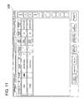
- FIG. 11 is a drawing showing an example of a portable
list reception screen to be displayed on the display 123 of
the control apparatus 120;
- FIG. 12(a) is a drawing showing an example of an input
screen for inputting patient information to be displayed on
the display 123 of the control apparatus 120;
- FIG. 12(b) is a drawing showing an example of an input
screen for inputting image pickup information to be displayed
on the display 123 of the control apparatus 120;
- FIG. 13 is a flow chart showing an image pickup start
processing to be practiced by the CPU 111 of the portable
terminal 110;
- FIG. 14(a) is a drawing showing an example of patient
list screen to be displayed on the display 113 of the
portable terminal 110;
- FIG. 14(b) is a drawing showing an example of display
screen to be displayed on the display 113 of the portable
terminal 110;
- FIG. 15 is a flow chart showing a post-image-pickup
processing to be practiced by the CPU 121 of the control
apparatus 120;
- FIG. 16 is a drawing showing an example of a portable
processing screen to be displayed on the display 123 of the
control apparatus 120; and
- FIG. 17 is a drawing showing the system structure of a
medical image pickup system of another mode of the embodiment
of this invention.
-
DETAILED DESCRIPTION OF THE PREFERRED EMBODIMENT
-
In the following, the embodiment of this invention will
be explained in detail with reference to the drawings.
(EBBODIMENT 1 OF THE INVENTION)
-
In this embodiment, it will be explained an example of
medical image processing system having a structure such that
image information of a patient having been inputted from one
of a plurality of input sections is outputted by one of a
plurality of output sections, wherein through which channel
the image information of a patient is outputted is recorded.
-
First, the structure will be explained.
-
In FIG. 1, the system structure of a medical image
processing system 100 of this embodiment is shown.
-
As shown in FIG. 1, the medical image processing system
100 is composed of a medical image generating apparatus 10 as
an input section, a candidacy abnormal shadow detecting
apparatus 30 as a diagnosis section, an image storage
apparatus 70 as an image saving section, and an output
apparatus 90 as an output section, and the apparatus are
connected to one another through a communication network N in
such a way as to be capable of transmitting and receiving
information. Further, the candidacy abnormal shadow
detecting apparatus 30, the image storage apparatus 70, and
the output apparatus 90 are medical image receiving apparatus
for receiving medical image data generated (image information
of a patient) from the medical image generating apparatus 10.
-
Besides, although the apparatus are shown in FIG. 1 in
a way such that one apparatus for each kind of them is
connected to the network N; however, the place of installment
and the number of apparatus are not limited to this example,
but it is possible that a plurality of apparatus for each of
the plural kinds of apparatus are installed. Further, also
it is appropriate that other apparatus concerning the
processing of medical images such as terminal apparatus
installed in every medical treatment department are connected
to the communication network N.
-
The communication network N is a LAN (Local Area
Network) to which various kinds of communication lines such
as a telephone line, a dedicated line, a mobile communication
network, a communication satellite network, and a CATV line
can be applied. Besides, also it is appropriate to apply
various kinds of network type such as a WAN (Wide Area
Network) and the Internet, but because medical images
transmitted and received through the communication network N
between the apparatus are personal information of patients,
from the viewpoint of reliability in the information control,
it is desirable that the communication network N is a
dedicated network with its security kept certainly.
-
Further, in this description, image information of a
patient (medical image data) and information such as an
attached bit of information to be described later are
supposed to be transmitted and received between the above-mentioned
sections by means of a standard signal based on
DICOM (Digital Imaging and Communications in Medicine)
standard. By this, digital communication between diagnosis
apparatus or treatment apparatus of different makers is
enabled.
-
In the following, every apparatus will be explained.
-
The medical image generating apparatus (input section)
10 generates digital image data (image information) for a
radiographed medical image of a patient. In this embodiment,
as regards the medical image generating apparatus, it will be
explained an example to which a CR (Computed Radiography)
apparatus which reads a radiographed radiation image of a
patient and converts it into digital image data is applied.
-
In FIG. 2, the functional structure of the medical
image generating apparatus 10 is shown.
-
As shown in FIG. 2, the medical image generating
apparatus 10 is equipped with an image data generator 11, an
image data memory 12, a communication device 13, a
transmission history storage 14, etc.
-
The image data generator 11 is composed of a cassette
accommodating an image pickup panel (a stimulable phosphor
sheet) having a stimulable phosphor layer formed, an
excitation light generation device, a photoelectric
conversion element such as a CCD (Charge Coupled Device)
image sensor, an A/D converter, etc. The image data
generator 11 makes radiation transmitted through an object
be absorbed by an image pickup panel, and irradiates this
image pickup panel with excitation light to scan the image
pickup panel. Further, it photoelectrically converts the
fluorescent light emitted from the image pickup panel into an
analog image signal, and further generates digital image data
through the A/D conversion of this analog image signal.
Generated image data are outputted to the image data memory
12.
-
In addition, for the image data generator 11, a flat
panel detector (Flat Panel Detector; hereinafter referred to
as an FPD) is applicable. An FPD, as described in the
publication of the unexamined patent application H6-342098
for example, has radiation detecting elements for generating
electric charge corresponding to the intensity of radiation
irradiating the elements and capacitors for accumulating the
electric charge generated by this radiation detecting
elements two-dimensionally arranged, and picks up a radiation
image of an object to output it as an electrical signal.
-
Further, the image data generator 11 provides a header
area for recording information on the medical image concerned
in the medical image data generated (image information), and
records, as bits of information attached to image, various
kinds of patient information such as the name of the patient
radiographed, the patient ID (ID for identifying the
patient), and the name of the doctor in charge of the
patient, and various kinds of image pickup information such
as the image pickup condition at the time of image pickup
(image pickup region, direction of image pickup), and the
date and time of image pickup.
-
Further, in this embodiment, the image data generator
11 is equipped with a function as an input information
recording section. Owing to this, it is actualized that, in
the header area of said medical image data (image
information), in addition to the above-mentioned various
kinds of information, information on the input section used
in the inputting of image information is recorded as input
information, and information on the cassette (or the
stimulable phosphor sheet accommodated in the cassette)
loaded in said input section and used in the inputting of
image information is recorded as cassette information.
-
In addition, for the input section information, for
example, it can be cited an individual bit of information to
be recorded for identifying the medical image generating
apparatus (input section) having generated the image
information concerned. For this individual bit of
information, it can be cited the case where individual
numbers are previously attached to their respective input
sections (respective medical image generating apparatus) and
the number concerned is recorded.
-
Further, for the cassette information, for example, it
can be cited an individual bit of information to be recorded
for identifying the cassette (or the stimulable phosphor
sheet accommodated in the cassette) having generated the
image information concerned. For this individual bit of
information, it can be cited the case where individual
numbers are previously attached to their respective cassettes
(or respective stimulable phosphor sheets) and the number
concerned is recorded.
-
Further, the image data generator 11 records, in the
above-mentioned header area, information on the inspection to
which the medical image belongs such as the inspection ID (ID
for individually identifying the inspection) and the
inspection requesting department. Because there is a case
where one and the same patient is radiographed a plurality of
times in different directions or by different image pickup
apparatus in a single inspection, the same inspection ID is
attached to image data belonging to one and the same
inspection, and when the medical image data are transmitted,
one or a plurality of sets of medical image data having the
same inspection ID attached are collectively transmitted as a
series of data group.
-
The image data memory 12 is made up of a magnetic or
optical recording medium, a semiconductor memory, or the
like, and stores medical image data (image information)
generated by the image data generator 11.
-
The communication device 13 is an interface capable of
being connected to the communication network N, and is
composed of a network interface card, a modem, a terminal
adapter, etc. The communication device 13 transmits medical
image data (image information) stored in the image data
memory 12 to the transmission end such as the candidacy
abnormal shadow detecting apparatus 30 and the image storage
apparatus 70.
-
The transmission history storage 14 is made up of a
magnetic or optical recording medium, semiconductor memory,
or the like, and saves information on the transmission
history of medical image data transmitted through the
communication device 13. For the information on the
transmission history, for example, bits of information such
as the name of image file of medical image data transmitted
and the date and time of transmission are saved.
-
Further, in this embodiment, the medical image data
generating means (input section) 10 is equipped with an image
information confirming section (the drawing omitted) for
displaying inputted image information for confirmation.
Further, if a defect of image information (disturbance of the
image, etc.) is discovered at the time of this confirmation,
by a manual input means (the drawing omitted, included in the
input information recording section), information indicating
the existence of a defect can be recorded as information
attached to image information.
-
In addition, the medical image generating apparatus is
not limited to the above-mentioned CR apparatus, but it is
also appropriate that, by the application of a laser
digitizer, digital image data is generated by a process such
that a film having a medical image recorded thereon is
scanned by a laser beam, the transmitted light quantity is
measured, and the light quantity value is subjected to
digital conversion. It is also appropriate to generate
medical image data by the application of a computerized
sectional radiography apparatus (hereinafter referred to as a
CT apparatus: a Computed Tomography apparatus), an MRI
apparatus, an ultrasonic image reading apparatus, etc.
-
Next, the candidacy abnormal shadow detecting apparatus
30 will be explained.
-
The candidacy abnormal shadow detecting apparatus
(diagnosis section) 30 is an image processing apparatus which
detects an image area appearing to be an abnormal shadow and
outputs it as a candidacy abnormal shadow by carrying out an
image analysis of medical image data.
-
In FIG. 3, the functional structure of the candidacy
abnormal shadow detecting apparatus 30 is shown.
-
As shown in FIG. 3, the candidacy abnormal shadow
detecting apparatus 30 is equipped with a communication
device 31, an image data memory 32, an image processor33, a
candidacy abnormal shadow detecting device 34, a control
device 35, and a display 36.
-
The communication device 31 is an interface capable of
connection to the communication network N, and is composed of
a network interface card, a modem, a terminal adapter, etc.
The communication device 31 receives medical image data
(image information of a patient) from the medical image
generating apparatus 10 for example, and transmits medical
image data (image information of a patient) having finished
being subjected to a processing of the detection of a
candidacy abnormal shadow and the result of the detection to
the output apparatus 90.
-
The image data memory 32 is made up of a magnetic or
optical recording medium, a semiconductor memory, or the
like, and stores image data received by the communication
device 31.
-
The image processor 33 applies various kinds of image
processing to medical image data inputted from the image data
memory 32, and outputs the data to the control device 35.
The above-mentioned various kinds of image processing include
a gradation processing for adjusting image contrast, a
contrast correction processing for detecting a candidacy
abnormal shadow, a frequency enhancement processing for
adjusting the sharpness of an image, a dynamic range
compression processing for making an image having a wide
dynamic range fall within a density range easy to observe
without lowering the contrast of minute portions of the
radiographic object, etc.
-
The candidacy abnormal shadow detecting device 34
detects an image area appearing to be an abnormal shadow by
reading out image data from the image data memory 32 and
carrying out an image analysis. In this embodiment, an
example in which a candidacy abnormal shadow is detected from
a mammogram will be explained; however, the object of the
detection is not limited to this, and it is also possible
that some other region such as a chest or an abdomen is
radiographed and a candidacy abnormal shadow in accordance
with the region is detected from the image.
-
In mammography, a shadow seeming to be a phyma
characterizing a breast cancer or a minute calcified cluster
is detected. A shadow of a phyma is a lump having a size of
a certain degree, and on a mammogram, it appears as a whitish
round shadow having a density distribution near a Gaussian
distribution. As regards a minute calcified cluster, if
minute calcified portions exist in a congregation (making a
cluster), the area has a high possibility to indicate a
cancer in the early stage. On a mammogram, it appears as a
whitish round shadow having approximately a conical shape.
-
Besides, it is put into practice to record the result
of image analysis by means of the above-mentioned candidacy
abnormal shadow detecting device 34 in relation to the
medical image concerned by a diagnosis result information
recording section (in this embodiment, this is included in
the candidacy abnormal shadow detecting device 34). In this
embodiment, it is recorded in such a manner as to be attached
to the data of the image information.
-
Further, the candidacy abnormal shadow detecting device
34 in this embodiment is provided with a function as a
diagnosis section information recording section which records
the information on the diagnosis section used in the
diagnosis of image information (the candidacy abnormal shadow
detecting apparatus 30) in the header area of the above-mentioned
medical image data (image information).
-
By this, in a case where there are plurality of the
above-mentioned diagnosis sections (the candidacy abnormal
shadow detecting apparatus 30) or in some case like that, it
is possible to identify the diagnosis section (the candidacy
abnormal shadow detecting apparatus 30) that has diagnosed
the image information concerned.
-
To state it concretely, it can be cited a case where
individual numbers are previously attached to their
respective diagnosis sections (the candidacy abnormal shadow
detecting apparatus 30), and the number concerned is
recorded.
-
The control device 35 is composed of a CPU (Central
Processing Unit), etc., and practices an output control of
medical image data to be outputted to the communication
device 31 or the display 36. The control device 35 outputs
the information on the detection result by the candidacy
abnormal shadow detecting device 34 to the communication
device 31, together with the medical image data having been
subjected to image processing by the image processor 33.
Further, the control device 35, when outputting medical image
data having been subjected to image processing to the 34, on
the basis of the detection result by the candidacy abnormal
shadow detecting device 34, outputs an image area of a
candidacy abnormal shadow in such a way as to make it
possible to identify the area of the candidacy abnormal
shadow by the marking with an arrow mark, the changing of the
color, or the like.
-
As regards the display means 36, a CRT (Cathode Ray
Tube), an LCD, a plasma display, etc. can be employed for it,
and among them, a high-definition, high-brightness CRT or
liquid crystal display dedicated to medical images is
desirable.
-
Next, the image storage apparatus 70 will be explained.
-
The image storage apparatus (image saving section) 70
is equipped with a communication device and a large-capacity
storage means such as a hard disk, and stores medical image
data (image information) transmitted from the medical image
data generating apparatus 10, the candidacy abnormal shadow
detecting apparatus 30, etc. provided on the communication
network, together with an attached bit of information, to
form a data base. The image storage apparatus 70, having
received a request of medical image data from any one of the
apparatus provided on the communication network N,
distributes the designated medical image data to the
designated transmission end.
-
In addition, in this embodiment, the above-mentioned
diagnosis section (candidacy abnormal shadow detecting
apparatus 30) is equipped with a defect information detecting
section which investigates attached bits of information
stored and saved in the image storage apparatus (image saving
section) concerned, and detects whether or not the above-mentioned
information on the existence of a defect is
present. If information indicating the existence of a defect
is detected in this section, by an identification section
provided in the diagnosis section, at least one of the input
section information and the cassette information (both in
this case) is detected and analyzed from the attached bit of
information having said information indicating the existence
of a defect recorded. Then, at least one of said input
section, cassette, and stimulable phosphor sheet (in this
case, the input section and cassette) is identified, and for
example, a display indicating a notification to that effect
is carried out by the output apparatus (in this case, a
display output apparatus) 90 to be described later. By the
practice of an investigation and maintenance operation for
the input section, the cassette, etc. based on this, it is
possible to efficiently remove a failure generating a
defective image information.
-
Next, the output apparatus 90 will be explained.
-
The output apparatus (output section) 90 is equipped
with a communication device and carries out the output of
medical image data (image information) received through the
communication network N.
-
As regards the output apparatus 90, a high-definition,
high-brightness CRT or liquid crystal display dedicated to
medical images, for example, a CRT (Cathode Ray Tube), a
liquid crystal display, a plasma display, etc. can be
employed for it.
-
Further, for the output apparatus 90, a film output
apparatus can be employed. In this case, the output
apparatus 90 applies an exposure processing to a film on the
basis of image data received through the communication
network N, to record the medical image data on the film.
-
Further, for the output apparatus 90, a printer or the
like which forms an image on a recording medium such as a
paper sheet on the basis of image data can be employed. In
this case, the output apparatus 90 forms an image on a
recording medium on the basis of image data received through
the communication network N, and outputs said recording
medium.
-
In addition, in this embodiment, any one of the above-mentioned
output sections (output apparatus 90 (display
output apparatus, film output apparatus, printer, etc.))
comprises an output section information recording section,
and is provided with a function to record the information
(output section information) on the output section (output
apparatus 90 (display output apparatus, film output
apparatus, printer, etc.)) used in the outputting (display,
printing, etc.) of the image information in the header area
of the above-mentioned medical image data (image
information).
-
By this, in a case where there are a plurality of kinds
of output section (for example, a display output apparatus, a
film output apparatus, a printer, etc.), in a case where
there are a plurality of apparatus for each kind, or in other
cases like that, it is possible to identify the output
section (the image storage apparatus 70 and the output
apparatus 90 (the display output apparatus, film output
apparatus, printer, etc.) having outputted (saved, displayed,
printed, etc.) the image information concerned.
-
For example, it can be cited a case where individual
numbers are previously attached to their respective output
sections (their respective image storage apparatus 70 and
their respective display output apparatus, film output
apparatus, printer, etc. as the output apparatus 90), and the
number concerned is recorded.
-
Further, in the case where a film output apparatus is
employed for the output apparatus, it is also appropriate to
record the kind, individual number, etc, of a photosensitive
film to be used in the outputting as bits of film information
in the output section information recording section.
-
Incidentally, for concrete examples of the header
information to be recorded in the header area of medical
image data (image information of a patient) or on a film
together with the image information, such items as described
below can be considered.
-
First, it is premised that the medical image processing
system 100 comprises 100 sheets of plate (cassette) (numbers
1 to 100 are defined for the plate ID), 10 input sections
(input apparatus) (numbers 1 to 10 are defined for the reader
ID), 10 output sections (a plurality of kinds of output
apparatus) (numbers 1 to 10 are defined for the imager ID).
-
Further, as regards the medical image generating
apparatus (input section) 10, the image storage apparatus
(output section) 70, and the output apparatus (output
section) 90, it is also appropriate that maintenance
operations for the apparatus are carried out and the version
upgrading of the control software for repairing failures or
upgrading the specification is also carried out even after
the installment of the apparatus, and in the input section
and output section, bits of information on the maintenance of
apparatus, version upgrading of the control software, etc.,
which have been converted into numerals, are recorded in
relation to the image information (as attached bits of
information). For example, it is also appropriate that bits
of status information such as information on the maintenance
or version upgrading as described above are converted into
numerals (numbers 1 to 10 are defined for the reader status
of the input section (reader), and numbers 1 to 10 are
defined for the imager status of the output section (imager))
and recorded. Further, it is also appropriate to make the
above-mentioned film information indicating the kind,
individual number, etc. of a photosensitive film to be used
in the outputting included in the imager status. In this
case, it is appropriate to convert the film information into
a predetermined numeral for recording.
-
Further, it is appropriate that the above-mentioned
numerals (numbers) are recorded in the order of, for example,
"plate ID/reader ID/reader status/imager ID/imager status",
that is, these are recorded in such an arrangement as
"55/3/5/6/4", which are made to be the bits of header
information.
-
Besides, it is possible that, among the above-mentioned
items, concerning those not required, the numerals
representing the items concerned are made to be "0" and the
items themselves are left existing, but sometimes an item
itself is deleted.
-
For example, in the case where the reader status is the
same for all the readers, it is possible to make the header
information such one as "plate ID/reader ID/imager ID/imager
status" with the item of the reader status omitted. Further,
there is also a case where the above-mentioned output section
information, input section information, etc. are made up not
of numerals but of signs.
-
Further, in the case where the output section is not an
apparatus which practices the outputting on a film or the
like (an apparatus which practices the outputting by
display), it is also appropriate that only the ID is attached
to the image information, detailed information is recorded in
another recording apparatus, and the using of the information
for perusal is enabled by the inputting of the ID.
-
Furthermore, in this embodiment, input section
information and output section information are made to be
recorded in the input section and the output section
respectively; however, this invention is not limited to this,
but it is also possible that the system is equipped (for
example, in the output section) with an input/output section
correlating section for collecting all the information, and
the input section information and the output section
information correlated here are recorded in the header area
or the like (as attached bits of information) in the
input/output section information recording section (provided
in the output section, for example). In this case, it may be
appropriate to further record the above-mentioned diagnosis
result information in relation to those.
-
Besides, in the case where image information is
recorded on a film in the output section, also the above-mentioned
information in the header area is recorded on the
film. Further, at this time, it is also appropriate to
record the kind, individual number, etc. of the
photosensitive film used as film information.
-
In addition, in cases as described in the above, by the
outputting based on the same data by means of different
imagers, it is enabled to immediately judge whether or not
the problem is specific to the imager. As regards the imager
having its cause of a failure clarified, it becomes possible
to maintain the image quality by the practice of suitable
maintenance operations, which is desirable.
-
Further, output apparatus generally require a
maintenance operation, and the image quality is often
improved after a maintenance operation; therefore, it is
preferable to add information on the condition of the
apparatus (condition about maintenance) on top of the
individual ID of each apparatus.
-
Further, in cases where a viewer is used, it can be
said that the above-mentioned thing is to be applied for
every changing of the LUT used.
-
As explained up to now, by a medical image processing
system of this embodiment, it is actualized that at least one
of input section information enabling the identification of
the input section (reader) used in the inputting and cassette
information enabling the identification of the cassette or
stimulable phosphor accommodated in the cassette loaded in
the above-mentioned input section and used in the output of
image information is recorded; therefore, in cases where a
failure is generated in image information, it is possible to
immediately judge whether or not the cause is in the input
section and/or in the cassette by the mere confirmation of
the input section and cassette concerned, and the pursuit of
the cause of the failure can be carried out easily.
-
Further, in this embodiment, there is provided an image
information confirming section such as a viewer for
displaying image information for confirmation, and if it is
discovered by the display for confirmation that there is a
defect in image information (for example, disturbance of
image information due to dusts etc.), information indicating
the existence of a defect can be recorded as information
attached to image information; therefore, it is possible to
easily discriminate between normal image information and
defective image information, and after that, the pursuit of
the cause of the failure can be quickly carried out.
-
Further, in this embodiment, in cases where image
information has a defect, at least one of the input section,
cassette, or stimulable phosphor sheet which have been used
in the inputting of the defective image information
concerned, is automatically identified, the pursuit of the
cause of the failure can be more simply carried out.
-
Furthermore, in this embodiment, image information is
transmitted and received between the sections by means of a
standard signal based on DICOM standard; therefore, the image
information can cope with various kinds of input apparatus
and output apparatus.
-
Further, by a medical image processing apparatus of
this embodiment, it is actualized that, when image
information is outputted to a photosensitive film in an
output section such as an imager, at least one of input
section information enabling the identification of the reader
used in the inputting, output section information enabling
the identification of the imager having carried out the
outputting concerned, and film information on the
photosensitive film used at the time of carrying out the
outputting concerned is recorded; therefore, in cases where a
failure of image information is generated, it is possible to
immediately judge whether or not the cause is in the input
section, output section, or film by the mere confirmation of
the input section, output section, and film concerned, and
the pursuit of the cause of the failure can be easily carried
out.
-
Further, in this embodiment, it is actualized that, in
the case where image information is outputted for display in
the output section such as a viewer, input section
information enabling the identification of the reader used in
the inputting and output section information enabling the
identification of the viewer used in the outputting concerned
are correlated with each other and then recorded; therefore,
in cases where a failure of image information is generated,
it is possible to immediately judge whether or not the cause
is in the input section or output section by the mere
confirmation of the input section and output section
concerned, and the pursuit of the cause of the failure can be
easily carried out.
-
Further, in this embodiment, it is actualized that, in
the case where image information is outputted for display in
an output section such as a viewer and diagnosis is carried
out on the basis of said image information, diagnosis result
information, together with input section information and
output section information, is also recorded in relation to
the image information; therefore, in cases where a failure of
image information is generated, it is possible to immediately
judge where the cause is by the mere confirmation of the
specified section, and the pursuit of the cause of the
failure can be easily carried out.
-
Furthermore, in this embodiment, it is actualized that,
when image information is inputted, input section information
enabling the identification of the reader used in the
inputting concerned is recorded as an attached bit of
information, and when image information is outputted for
display in an output section such as a viewer, output section
information enabling the identification of the viewer used in
the outputting concerned is further recorded as an attached
bit of information; therefore, in cases where a failure of
image information is generated, it is possible to immediately
judge whether or not the cause is in the input section or
output section by the mere confirmation of the input section
and output section concerned, and the pursuit of the cause of
the failure can be easily carried out.
-
Further, in this embodiment, it is actualized that,
when image information is inputted, input section information
enabling the identification of the reader used in the
inputting concerned is recorded as an attached information,
and when image information is outputted for display in an
output section such as a viewer, output section information
enabling the identification of the viewer used in the
outputting concerned is recorded as an attached bit of
information, while result information of the diagnosis
carried out on the basis of image information is recorded as
an attached bit of information; therefore, in cases where a
failure of image information is generated, it is possible to
immediately judge where the cause is by the mere confirmation
of the specified section, and the pursuit of the cause of the
failure can be easily carried out.
-
Further, in this embodiment, it is actualized that
status information of an input section and that of an output
section are recorded in relation to input section information
and output section information; therefore, in cases where a
failure of image information is generated, it is possible to
immediately judge where the cause is more simply, and the
pursuit of the cause of the failure can be easily carried
out.
-
In addition, it is appropriate that the image
processing includes gradation processing, frequency
processing, correction processing of pixel size, correction
processing of the number of gray levels, dynamic range
compression processing (the publication of the unexamined
patent application H3-222577), abnormal shadow detection
processing (the publication of the unexamined patent
application S62-125481), position adjustment processing for
correcting a positional deviation of corresponding portions
between a plurality of images (the publication of the
examined patent application S61-14553, and the publication of
the unexamined patent applications S63-278183 and H1-70236),
frequency processing using a multi-resolution method (the
publication of the unexamined patent application H11-345331),
etc.
-
In addition to the above-mentioned, concerning the
detailed structure and detailed operation of an medical image
processing system of this embodiment also, it is possible to
suitably modify them within a range not departing from the
intention of this invention.
(EMBODIMENT 2 OF THE INVENTION)
-
In the following, the embodiment 2 of this invention
will be explained in detail with reference to the drawings.
However, the scope of the invention is not to be limited to
the examples shown in the drawings. Besides, in the
following, as an example of the embodiment characterizing
this invention, a medical image pickup system for carrying
out radiographing at a site of round visits utilizing a
portable terminal and a movable image pickup apparatus will
be explained.
-
First, the structure of this embodiment will be
explained.
-
FIG. 4 is a conceptual drawing showing the system
structure of a medical image pickup apparatus 1100 of this
invention. As shown in FIG. 4, the medical image pickup
system 1100 is composed of portable terminals 110,
communication terminals 110-1, control apparatus 120, medical
image reading apparatus 130, a portable image pickup
apparatus 140, a cassette 150, an information administration
apparatus 160, etc. Further, the control apparatus 120, the
medical image reading apparatus 130, and the information
administration apparatus 160 are connected to one another
through a network N, and the portable terminals 110 and their
respective control apparatus 120 have a structure such that
they can be connected with each other through the respective
communication terminals 110-1.
-
The portable terminal 110 is an information terminal
apparatus of a portable type carried by a radiological
technologist (radiographer) who operates the portable image
pickup apparatus 140, and carries out communication with the
control apparatus 120 through the communication terminal 110-1
to be described later. Further, the portable terminal 110
acquires image pickup order information from the control
apparatus 120 and displays it, and in a case where there are
image pickup orders of plural patients, the portable terminal
110 retrieves and displays the image pickup order information
corresponding to the desired patient ID out of the image
pickup order information of the plural patients. Further,
the portable terminal 110, when starting image pickup,
acquires the identification information of the radiographer
(hereinafter referred to as "radiographer ID"), the
identification information of the cassette 150 (hereinafter
referred to as "cassette ID"), and the identification
information of the image pickup apparatus (hereinafter
referred to as "image pickup apparatus ID, and stores them in
correspondence with the image pickup order information.
-
The communication terminal 110-1 is connected with the
control apparatus 120 through a cable or the like, and
controls the transmission and reception of data between the
portable terminal 110 and the control apparatus 120 connected
to the communication terminal 110-1. For example, the
communication terminal 110-1 controls the transmission of
image pickup order information from the control apparatus 120
to the portable terminal 110, and controls the transmission
of a radiographer ID, a cassette ID, and an image pickup
apparatus ID from the portable terminal to the control
apparatus 120.
-
The control apparatus 120 is an apparatus which
receives image pickup order information from the information
administration apparatus 160 and controls medical images on
the basis of the received image pickup order information, and
also controls image pickup history of medical images on the
basis of information received from the portable terminal 110
and the medical image reading apparatus 130. For example,
the control apparatus 120 transmits image pickup order
information received from the information administration
apparatus 160 to the portable terminal 110 through the
communication terminal 110-1. Further, the control apparatus
120, after an image pickup has been finished, receives the
radiographer ID, cassette ID, and image pickup apparatus ID
brought in correspondence with the image pickup order
information.
-
Further, the control apparatus 120 receives a medical
image, the cassette ID brought in correspondence with the
medical image, and the identification information of the
reading apparatus (hereinafter referred to as "reading
apparatus ID") from the medical image reading apparatus 130.
Further, the control apparatus 120 controls a medical image,
a radiographer ID, a cassette ID, an image pickup apparatus
ID, a reading apparatus ID, etc. in correspondence with one
another on the basis of image pickup order information.
Further, the control apparatus 120 transmits a medical image,
a radiographer ID, a cassette ID, an image pickup apparatus
ID, and a reading apparatus ID to the information
administration apparatus 160 in correspondence with image
pickup order information.
-
The medical image reading apparatus 130 is a medical
image reading apparatus for reading a medical image recorded
in the cassette 150. The medical image reading apparatus 130
irradiates a stimulable phosphor sheet in the cassette 150
with excitation light, the stimulation light emitted from the
sheet by the excitation light is photoelectrically converted,
and the obtained image signal is subjected to A/D conversion,
to become medical image data. Further, the medical image
reading apparatus 130 reads the cassette ID attached to the
cassette 150, and transmits the medical image data, the
cassette ID, and the reading apparatus ID of its own
apparatus to the control apparatus 120 in correspondence with
one another.
-
The portable image pickup apparatus 140 is a movable
medical image pickup apparatus, and carries out an image
pickup of a patient at a site of round visits, to record a
medical image in the cassette 150 which is capable of being
mounted and dismounted in the apparatus mainframe. The
cassette 150 has a built-in stimulable phosphor sheet for
accumulating a part of radiation energy, and accumulates a
part of radiation energy having emitted from the radiation
source and passed a test object disposed between the
radiation source and the cassette in the above-mentioned
stimulable phosphor sheet. In addition, on the surface of
the cassette 150, a bar code or the like for indicating the
cassette ID standing for the identification information of
the cassette 150.
-
The information administration apparatus 160 is a
terminal for collectively control a plurality of sets of
image pickup order information designated by a doctor; in
response to the requirement instruction from the control
apparatus 120, it extracts a set of image pickup order
information, which is transmitted by it to the control
apparatus 120. Besides, as regards another information
administration apparatus, a reception apparatus (not shown in
the drawing) for carrying out the reception of booking of
image pickup orders may be employed; that is, it is also
appropriate to employ an information control system such as
an HIS (Hospital Information System) and an RIS (Radiology
Information System).
-
For the network N, various types of line such as a LAN
(Local Area Network), a WAN (Wide Area Network), and the
Internet can be employed. Besides, a wireless communication
or an infrared communication may be employed so long as it is
permitted for the use in a medical treatment organization
such as a hospital; however, because important information of
a patient is included in the transmission and reception of
image pickup order information, it is desirable to make image
pickup order information a cipher.
-
Next, apparatus which are regarded as principal
structural elements of this invention will be explained in
detail.
-
FIG. 5 is a block diagram showing the functional
structure of the portable terminal 110. As shown in FIG. 5,
the portable terminal 110 is composed of a CPU 111, an
operation section 112, a display 113, an I/F 114 as a
communication device, a RAM 115, a storage device 116 as a
storage means, a bar code reader 117 as an acquisition means,
etc., and all the sections are connected one another through
a bus 118.
-
The CPU (Central Processing Unit) 111 runs a program
which is designated out of a system program and various kinds
of application program stored in the storage device 116 on
the RAM 115, and controls every unit of the portable terminal
110 in accordance with said program.
-
To state it concretely, the CPU 111 reads out an image
pickup preparation processing program and an image pickup
start processing program from the storage device 116, and
practices an image pickup preparation processing (refer to
FIG. 9(b)) and an image pickup start processing (refer to
FIG. 13) to be described later. In addition, the detail of
the processings will be described later.
-
The operation section 112 is equipped with a cursor
key, numeral keys, various kinds of functional key, etc., and
outputs a depress signal corresponding to a key depressed by
the radiographer to the CPU 111. Further, the operation
section 112 is equipped with a jog-dial key, and outputs an
instruction signal for scrolling (moving) the information
displayed on the display 113 to the CPU 111 in response to
the operation of the jog-dial key. Further, when the jog-dial
key is depressed, it outputs a depress signal for the
displayed information to the CPU 111. In addition, the
operation section 112 may be equipped with a pointing device
such as a touch panel, or some other input device as occasion
demands.
-
The display 113 is a display means equipped with a
display based on an LCD (Liquid Crystal Display) or the like,
and displays image pickup order information and various kinds
of information such as a patient ID, a radiographer ID, a
cassette ID, an image pickup apparatus ID acquired on the
basis of display instruction from the CPU 111.
-
The I/F 114 is an interface for connecting the portable
terminal 110 with the communication terminal 110-1, and when
the portable terminal 110 is connected to the communication
terminal 110-1, it outputs a detection signal to the CPU 111.
Further, the I/F 114 carries out the adjustment of data
transfer speed and the transformation of data format between
the portable terminal 110 and the control apparatus 120
through the communication terminal 110-1, to mediate between
both the apparatus for give-and-take of data.
-
For example, the I/F 114 receives image pickup order
information from the control apparatus 120, and after the end
of an image pickup operation, it also transmits the
radiographer ID, cassette ID, and image pickup apparatus ID
brought in correspondence with the image pickup order
information to the control apparatus 120. In addition, the
I/F 114 has a structure such that it has a cellular phone
terminal such as a PHS connected with it, and establishes a
wireless communication system to carry out transmission and
reception of data.
-
The RAM (Random Access Memory) 115 has a work memory
area for storing the above-mentioned designated application
program, an input instruction, input data, the result of
processing, etc.
-
The storage device 116 comprises a storage medium (not
shown in the drawing) having programs and data previously
stored, and this storage medium stores a system program,
various kinds of application program corresponding to said
system program, and data obtained by the processing by
various kinds of processing program. Further, this storage
medium is made up of a magnetic or optical storage medium or
a semiconductor memory, and is fixedly provided in the
storage device 116 or is mounted in such a way as to be
capable of being mounted or dismounted.
-
Further, the storage device 116 stores an image pickup
order information file 1161 for storing image pickup order
information received from the control apparatus 120. The
image pickup order information file 1161 will be explained
with reference to FIG. 6. FIG. 6 is a drawing showing an
example of the data structure of the image pickup order
information file 1161. As shown in FIG. 6, the image pickup
order information file 1161 has items for storing the image
pickup ID, patient ID, name, sex, age, patient room,
requesting department, image pickup region, number of image
sheets, and items for storing the radiographer ID, cassette
ID, image pickup apparatus ID which are acquired at the start
of image pickup, and stores data corresponding to each of the
items for each image pickup order information.
-
In the item of image pickup ID, identification codes
allotted uniquely for the identification of their respective
image pickup works (for example, 20020101001, 20020101002,
20020101003, ---) are stored. In the item of patient ID,
identification codes allotted uniquely for the identification
of the respective patients to be subjected to image pickup
(for example, 10000002, 10000005, ---) are stored. In the
item of name, bits of character information indicating the
name of the respective patients to become the object of image
pickup are stored, and in the item of sex, bits of character
information indicating the sex of the respective patients to
become the object of image pickup are stored. In the item of
age, bits of numeral information indicating the age of the
respective patients to become the object of image pickup are
stored, and in the item of patient room, bits of character
information indicating the respective patient rooms to become
the image pickup site are stored.
-
In the item of requesting department, bits of character
information indicating the respective requesting departments
having requested image pickup are stored, in the item of
image pickup region, bits of information indicating the
respective image pickup regions (for example, skull A → P,
skull P → A, chest P → A, ---) are stored, and in the item
of number of image pickup sheets, the number of sheets of the
respective medical images to be radiographed are stored as
bits of numeral information (for example, 3, 4, 5, ---).
-
In the item of radiographer ID, identification codes
uniquely allotted for the identification of the respective
radiographers having practiced the image pickup work (for
example, bits of information to be read from the bar code
attached to the ID card or the like owned by the respective
radiographers) are stored. In the item of cassette ID,
identification codes uniquely allotted for the identification
of the respective cassettes having been used in the image
pickup operation (for example, bits of information to be read
from the bar code or the like attached to the respective
cassettes 150) are stored. In the item of image pickup
apparatus ID, identification codes uniquely allotted for the
identification of the respective portable image pickup
apparatus 140 having practiced the image pickup process (for
example, bits of information to be read from the bar code or
the like attached to the respective portable image pickup
apparatus 140).
-
In addition, the data of the above-mentioned
radiographer ID, cassette ID, and image pickup apparatus ID
are not stored in the image pickup order information file
1161 before the image pickup process, and the data for the
above-mentioned items read by the bar code reader 117 at the
start of the image pickup process are made to be stored.
-
Further, it is also possible to make the image pickup
order information have such a structure as to store, in
addition to the patient ID, name, sex, and age for the
patient information, various kinds of patient information
such as the name of the doctor in charge of the patient,
warning information to make warning for an infectious
disease, being allergic to medical substances or not, being
pregnant or not, additional medical history, necessity of a
special care such as a wheel chair or a stretcher, the name
of clinical diagnosis, and secrecy matters. Further, also it
is appropriate to make the image pickup order information
have such a structure as to store, in addition to the image
pickup region, image pickup apparatus, number of image pickup
sheets for the image pickup information, various kinds of
image pickup information such as the method of radiographing
(simple radiographing, contrast medium radiographing, etc.),
and planned image pickup date.
-
The bar code reader 117 is an example of an acquisition
means for acquiring a radiographer ID, cassette ID, image
pickup apparatus ID, etc., and is equipped with a scanner,
which is an optical reading device. The bar code reader 117
acquires information indicated by a bar code through reading
a bar code by the scanner and decoding it in accordance with
a specified standard. For example, the bar code reader 117
reads a barcode attached to an ID card or the like of a
radiographer, and acquires the radiographer ID when an image
pickup operation is carried out, and reads a bar code
attached to the cassette 150 for recording a medical image,
and acquires the cassette ID.
-
Further, the bar code reader 117 reads a bar code
attached to the bed side of a patient or a part of the body
of a patient, and acquires the patient ID; further, it reads
a bar code attached to an image pickup apparatus, and
acquires the image pickup apparatus ID. In addition, the
term "specified standard" means JAN code, UPC code, CODE39,
CODE93, CODE128, NW-7, INDUSTRIAL 2 of 5, ITF physical
distribution code, etc.
-
FIG. 7 is a block diagram showing the functional
structure of the control apparatus 120. As shown in FIG. 7,
the control apparatus 120 is equipped with a CPU 121, an
input section 122, a display 123, a communication controller
124, a RAM 125, a memory apparatus 126, an I/F 127, etc., and
all the sections are connected with a bus 128.
-
The CPU 121 reads out a system program and various
kinds of control program stored in the storage device 126,
runs a program on the RAM 125, and makes a centralized
control of the operation of every section in accordance with
said control program. Further, the CPU 121 practices various
kinds of processing in accordance with a program developed on
the RAM 125, makes the RAM 125 store the processing result,
and makes the display 123 display it.
-
To state it concretely, the CPU 121 reads out an image
pickup preparation processing program and a post-image pickup
processing program from the storage device 126, and practices
an image pickup preparation processing (refer to FIG. 9(a))
and a post-image pickup processing (refer to FIG. 15) to be
described later.
-
The input section 122 includes a key board equipped
with a cursor key, numeral keys, various kinds of functional
key, etc., and outputs a depress signal corresponding to a
key depressed in this key board to the CPU 121. Further, it
is also appropriate that the input section 122 is equipped
with a pointing device such as a mouse or a touch panel, or
with some other input device as occasion demands.
-
The display 123 is made up of an LCD, a CRT (Cathode
Ray Tube), or the like, and displays an input instruction,
data, etc. received from the input section 122 in accordance
with an instruction based on a display signal inputted from
the CPU 121.
-
The communication control section 124 is made up of a
LAN adapter, a router, a TA (Terminal Adapter), or the like,
and controls the communication between the apparatus
connected to the network N through a dedicated line or a
communication line such as an ISDN line.
-
The RAM 125 has a storage area formed for temporarily
storing a system program and a control program, which are
practicable by the CPU 121 and read out from the storage
device 126, input or output data, parameters, etc., in the
various kinds of processing to be practiced and controlled by
the CPU 121.
-
The storage device 126 is made up of an HDD (Hard Disk
Drive), a non-volatile semiconductor memory, or the like, and
stores a system program, various kinds of processing program
corresponding to said system program to be practiced by the
CPU 121, results of processing, etc. Further, it comprises
a storage medium (not shown in the drawing) having programs
and data previously stored; this storage medium is made up of
a magnetic or optical storage medium or a semiconductor
memory, and is fixedly provided in the storage device 126 or
is mounted in such a way as to be capable of being mounted or
dismounted. These various kinds of program are stored in a
form of a readable program code, and the CPU 121 practices
successively the operations in accordance with the program
code concerned.
-
Further, the storage device 126 stores an image pickup
order information file (not shown in the drawing) for storing
image pickup order information received from the information
administration apparatus 160 and an image pickup history
administration file 1261 for controlling the image pickup
history of a medical image. In addition, because the image
pickup order information file has approximately the same
structure as the above-mentioned image pickup order
information file 1161 (refer to FIG. 6), its drawing and
detailed explanation will be omitted. With reference to FIG.
8, the image pickup history administration file 1261 will be
explained.
-
FIG. 8 is a drawing showing an example of the data
structure of the image pickup history administration file
1261. As shown in FIG. 8, in the image pickup history
administration file 1261, there are provided items for
storing an image pickup ID, an image pickup date, a
radiographer ID, a cassette ID, an image pickup apparatus ID,
a reading apparatus ID, and an error flag.
-
In the item of image pickup ID, identification codes
uniquely identifying the respective bits of image pickup
order information stored in the above-mentioned image pickup
order information file 1161 (for example, 20020101001, ---)
are stored, and by the image pickup ID, data stored in other
items are brought into correspondence with the above-mentioned
image pickup order information. In the item of
image pickup date, bits of information indicating the date
when the respective medical images were radiographed (for
example, 2003/3/3, ---) are stored.
-
In the item of radiographer ID, bits of identification
information uniquely identifying the respective radiographers
having radiographed the respective medical images (for
example, sato1234, ---) are stored, and in the item of
cassette ID, bits of identification information uniquely
identifying the respective cassettes having stored the
respective medical images (for example, 04000108022016, ---)
are stored. In the item of image pickup ID, bits of
identification information uniquely identifying the
respective image pickup apparatus or the respective portable
image pickup apparatus 140 (for example, A101010, ---) are
stored.
-
In the item of reading apparatus ID, bits of
identification information uniquely identifying the
respective medical image reading apparatus 140 having read
the respective medical images from the respective cassettes
150 (for example, E1100101, ---) are stored, and in the item
of error flag, check flags for indicating whether or not an
error is generated in the respective medical images.
-
In addition, the above-mentioned image pickup ID, image
pickup date, radiographer ID, cassette ID, and image pickup
apparatus ID are information transmitted from the portable
terminal 110 in the post-image pickup processing to be
described later, and the reading apparatus ID is information
transmitted from the medical image reading apparatus 140.
Further, the information on whether or not an error flag has
been checked is information inputted by the radiographer in
the post-image pickup processing. Besides, the kinds of
information to be stored in the image pickup history
administration file 1261 are not limited to the above-mentioned
examples, and it is possible to store various kinds
of information other than those as occasion demands.
-
The I/F 127 is an interface for connecting the control
apparatus 120 with the communication terminal 110-1, and when
it is detected that the portable terminal 110 has been
connected with the communication terminal 110-1, it outputs a
detection signal to the CPU 111. Further, the I/F 127
carries out the adjustment of data transfer speed and the
transformation of data format between the control apparatus
120 and the portable terminal 110 through the communication
terminal 110-1, to mediate both the apparatus for give-and-take
of data. For example, the I/F 127 transmits image
pickup order information to the portable terminal 110 before
the start of an image pickup process, and also receives the
radiographer ID, cassette ID, and image pickup apparatus ID
having been brought into correspondence with the image pickup
order information from the portable terminal 110 after the
completion of the image pickup process.
-
Next, the medical image reading apparatus 130 will be
explained. In addition, because the functional structure of
the medical image reading apparatus 130 is approximately the
same as that of the above-mentioned control apparatus 120,
the corresponding signs are attached to the same parts and
the drawings and detailed explanation will be omitted. That
is, the medical image reading apparatus 130 is equipped with
a CPU 131, an input section 132, a display section 133, a
communication controller 134, a RAM 135, an image reading
section 137, a bar code reader 138, etc., and all the
sections are connected with one another through a bus 139.
-
The image reading section 137 irradiates a stimulable
phosphor layer in the cassette 150 by excitation light to
make it emit fluorescent light corresponding to the radiation
energy accumulated, and photoelectrically converts the
emitted fluorescent light; thus, radiation image data are
acquired.
-
The bar code reader 138 is an example of an acquisition
means for acquiring a cassette ID, and is equipped with a
scanner which is an optical reading device. The bar code
reader 138 reads a bar code attached to the surface of the
cassette 150 loaded in the image reading section 137, and
acquires the cassette ID.
-
The CPU 131 acquires a medical image read by the image
reading section 137, a cassette ID read by the bar code
reader 138, and a reading apparatus ID identifying uniquely
the medical image reading apparatus having carried out the
reading of the medical image, that is, its own apparatus,
controls the communication control section 134, and brings
the cassette ID and the reading apparatus ID in
correspondence with the medical image, to transmit these to
the control apparatus 120. In this case, it is desirable
that the cassette ID and reading apparatus ID which have been
brought in correspondence with the medical image are
transmitted on the basis of DICOM (Digital Imaging and
Communications Medicine) standard, for example.
-
Next, the operation of a system of this embodiment will
be explained.
-
In addition, a program for actualizing each of the
functions described in the flow chart to be described later
is stored in the storage device 116 of the portable terminal
110, in the storage device 126 of the control apparatus 120,
or in the storage device 136 of the medical image reading
apparatus 130 in a format of a program code capable of being
read by a computer, and the CPU 111 of the portable terminal
110, the CPU 121 of the control apparatus 120, or the CPU 131
of the medical image reading apparatus 130 successively
practices the operations in accordance with the program code
concerned.
-
First, as a preparation processing for the practice of
an image pickup process, an image pickup preparation
processing to make the portable terminal acquire image pickup
order information from the control apparatus 120 will be
explained.
-
FIG. 9(a) is a flow chart showing an image pickup
preparation processing to be practiced by the CPU 121 of the
controller 120. As shown in FIG. 9(a), when an instruction
for the transmission of image pickup order information is
inputted by a radiographer through the input section 122
(step S1), the CPU 121 controls the I/F 127 to judge whether
or not the portable terminal 110 is connected with the
communication terminal 110-1 (step S2). Now, if the portable
terminal 110 is not connected with the communication terminal
110-1 (step S2: NO), the CPU 121 carries out an error display
on the display 123, and this image pickup preparation
processing is finished.
-
On the other hand, if the portable terminal 110 is
connected with the communication terminal 110-1 (step S2:
YES), the CPU 121 acquires the image pickup order information
from the storage device 126, and transmits the image pickup
order information to the portable terminal 110 through the
communication terminal 110-1 (step S3). Then, the CPU 121
sets to ON the transmission flag of the image pickup order
information having been transmitted (step S4), to complete
this image pickup order information transmission processing.
-
FIG. 9(b) is a flow chart showing an image pickup
preparation processing to be practiced by the CPU 111 of the
portable terminal 110. As shown in FIG. 9(b), the portable
terminal 110 is connected with the communication terminal
110-1 in order to acquire an image pickup order information
(step S11).
-
Subsequently, the CPU 111 controls the I/F 114, to
receive image pickup order information transmitted from the
control apparatus 120 (step S12). Then, the CPU 111 makes
the image pickup order information file 1161 in the storage
device 116 store the received image pickup order information
(step S13), to finish this image pickup order information
acquisition processing.
-
The display screen to be displayed on the display 123
of the control apparatus 120 in the above-mentioned image
pickup preparation processing will be explained with
reference to FIG. 10 to FIG. 12(b).
-
FIG. 10 is a drawing showing a menu screen 1231 for
selecting a desired processing. As shown in FIG. 10, in the
menu screen 1231, there are provided designation buttons for
designating the menus "System state", "Selection of
radiographer", "Inspection history", "Utility", "Screen
format", and "Operation mode" respectively. Further, at each
of the designation buttons for the "Screen format" and
"Operation mode", an input item is provided; for example,
when "portable" is inputted in the input item for the
"Operation mode" and the button concerned is designated, the
portable mode screen for the case where an image pickup
process is carried out by the portable image pickup apparatus
140 is displayed. Further, when "normal" is inputted in the
input item for this "Operation mode", the normal mode screen
for the case where an image pickup process is carried out in
a normal image pickup room is displayed.
-
FIG. 11 is a drawing showing a portable list screen
1232 on which image pickup order information is displayed as
an overall list. As shown in FIG. 11, in the portable list
screen 1232, an area for displaying image pickup order
information and an area for displaying designation buttons
for inputting various kinds of designation are provided. In
the area for displaying image pickup order information, as a
part of image pickup order information, there are provided
items for displaying the patient ID, tab, name, sex, date of
birth, image pickup region, number of image pickup sheets,
and suspension, and in each of the items, the corresponding
data is displayed.
-
Further, near the right edge and lower edge of the
portable list screen 1232, in the area for displaying
designation buttons for inputting various kinds of
designation, in addition to a selection key, there are
provided designation buttons having respective text data of
"transmission", "reception", "new/search", "correction",
"delete", ---, "confirmation screen" displayed, and by each
of the designation buttons being operated through the input
section 122, the corresponding designation is inputted. For
example, when the image pickup order information displayed on
the portable list screen 1232 is selected by the selection
key, and "transmission" key is operated, the selected image
pickup order information is transmitted to the portable
terminal 110. Now, when the image pickup order information
is transmitted to the portable terminal 110, the transmission
completion flag for the image pickup order information
concerned is set to ON, and in the item of "tab", the check
flag for the completion of transmission "→" is displayed.
Further, when the designation button "new/search" is
operated, the input screens 1233 and 1234 for newly
registering image pickup order information are displayed.
-
FIG. 12(a) and FIG. 12(b) are drawings showing the
input screens 1233 and 1234 to be displayed in the case where
the "new/search" designation button is operated in the above-mentioned
portable list screen 1232. FIG. 12(a) is a drawing
showing the input screen 1233 for newly inputting patient
information in image pickup order information. As shown in
FIG. 12(a), in the input screen 1233, there are provided an
area for inputting patient information and an area for
displaying character keys for carrying out character input.
-
In the area for inputting patient information displayed
in the upper area of the input screen 1233, there are
provided items for inputting the patient ID, name of the
patient (romaji, kana, kanji), sex, date of birth, and
comment, and an inputted data is to be displayed in the
corresponding item in response to the operation of the input
section 122. Further, in the area for displaying the
character keys displayed in the lower area of the input
screen 1233, the key input corresponding to the displayed
character key concerned is carried out through a mouse or a
touch panel provided in the input section 122. In addition,
it is also possible to carry out the key input through a key
board provided in the input section 122.
-
FIG. 12(b) is a drawing showing the input screen 1234
for inputting image pickup information out of a set of image
pickup order information. As shown in FIG. 12(b), in the
image pickup information input screen 1234, there are
provided an area for displaying designation buttons each
designating an image pickup region as an image pickup
condition, an area for displaying designation buttons each
designating an image pickup direction in an image pickup
region, and an area for displaying the inputted image pickup
region and image pickup direction.
-
In the area for displaying the designation buttons for
image pickup region displayed in the upper left part of the
input screen 1234, there are provided designation buttons
having text data of, for example, "head", "neck", ---, and
"TEST" displayed respectively, and by each of the designation
buttons being designated through the input section 122, the
corresponding image pickup region is selected. Further, in
the area for displaying the designation buttons for image
pickup direction displayed in the middle left part of the
input screen 1234, half-tone line meshing displays are made,
and these cannot be selected in the portable mode. That is,
the half-tone line meshing indicates that the image pickup
region to be displayed in said area is an image pickup region
incapable of being radiographed by the portable image pickup
apparatus 140. In addition, as a method of displaying non-selectable
regions, in addition to the half-tone line
meshing, it is possible to make them non-display or non-active
display. Further, it is also appropriate to output a
warning by a voice or an image, in the case where a non-selectable
designation button is designated.
-
Further, in the area for displaying the designation
buttons of image pickup direction displayed in the lower left
part of the input screen 1234, there are provided designation
buttons having text data of "oblique position", ---,
"pneumoconiosis" displayed respectively as the image pickup
directions in the image pickup region "chest, other" for
example, and by each of the designation buttons being
designated through the input section 122, the corresponding
image pickup direction is selected. Further, in the area for
displaying the image pickup region and image pickup direction
displayed in the rightward part of the input screen 1234, an
image pickup region and image pickup direction selected by
one of the above-mentioned designation buttons being
designated is displayed as "chest, other; oblique position",
for example.
-
Next, it will be explained an image pickup start
processing in which, in a patient room where an image pickup
process is to be carried out, before the start of the image
pickup process, an operation to bring the patient ID in
correspondence with the image pickup order information is
carried out, and the radiographer ID, cassette ID, and image
pickup apparatus ID are stored in correspondence with the
image pickup order information.
-
FIG. 13 is a flow chart showing an image pickup start
processing to be practiced by the CPU 111 of the portable
terminal 110. As shown in FIG. 13, the CPU 111 controls the
bar code reader 117, and reads a bar code attached to the bed
side of the patient or to a part of the patient body, to
acquire the patient ID (step S21). Subsequently, the CPU 111
acquires from the storage device 116 the image pickup order
information corresponding to the patient ID having been read
(step S22).
-
Subsequently, the CPU 111 makes the display 113 display
the acquired image pickup order information (step S23), while
it controls the bar code reader 117, and reads the bar codes
attached to the radiographer practicing the image pickup
operations, the cassette 150, and the portable image pickup
apparatus 140 respectively, to acquire the radiographer ID,
the cassette ID, and the image pickup apparatus ID (step
S24). Then, the CPU 111 makes the storage device 116 store
the acquired radiographer ID, cassette ID, and image pickup
ID in correspondence with the image pickup order information
(step S25), to complete this image pickup start processing.
-
It will be explained with reference to FIG. 14(a) and
FIG. 14(b), a display screen displayed on the display section
of the portable terminal 110 in the above-mentioned image
pickup start processing. FIG. 14(a) is a drawing showing a
patient list screen 1131 for displaying the patients
registered in the portable terminal 110 as an overall list.
As shown in FIG. 14(a), in the patient list screen 1131,
there is provided an area indicating patient information, and
in this area, there are provided items for displaying a
patient ID, a patient name, and a ward respectively. To
state it concretely, in the item of patient ID, a numeral
data "0001" is displayed, and in the item of name, a text
data "Yamada Ichiro (in kanji)" is displayed.
-
FIG. 14(b) is a drawing showing a display screen 1132
for displaying image pickup order information of the
corresponding patient in the case where a patient ID is
acquired by the bar code reader 117 of the portable terminal
110. As shown in FIG. 14(b), in the display screen 1132,
there are provided an area for displaying patient information
and an area for displaying image pickup information. In the
area for displaying patient information, there are provided
items for displaying a patient ID, sex, age, ward, patient
room respectively, and in each of the items, the
corresponding data is displayed.
-
Further, in the area for displaying image pickup
information, there are provided items for displaying an image
pickup region, cassette ID, radiographer ID, image pickup
apparatus ID respectively, and in each of the items of
cassette ID, radiographer ID, image pickup apparatus ID,
corresponding data acquired by the bar code reader 117 of the
portable terminal 110 is displayed at the same time of the
reading. To state it concretely, in the item of image pickup
region, a text data "chest, other; oblique position" is
displayed, and in the item of cassette ID, a numeral data
"04000108022016" is displayed. Further, in the item of
radiographer ID, a text-numeral data "suzuki777" is
displayed, and in the item of image pickup apparatus ID, a
text-numeral data "A101010" is displayed.
-
Subsequently, it will be explained a post-image pickup
processing in which, after the completion of an image pickup
process, in the control apparatus 120, the radiographer ID,
cassette ID, and image pickup apparatus ID having been
brought in correspondence with the image pickup order
information of the finished image pickup process are acquired
from the portable terminal 110, and also the medical image,
cassette ID, and reading apparatus ID having been read from
the medical image reading apparatus 130 are acquired.
-
FIG. 15 is a flow chart showing a post-image pickup
processing to be practiced by the CPU 121 of the control
apparatus 120. As shown in FIG. 15, when the CPU 121
receives the radiographer ID, cassette ID, and image pickup
ID having been brought in correspondence with the image
pickup order information of the finished image pickup process
from the portable terminal 110 (step S31; YES), it makes the
image pickup history administration file 1261 store the
radiographer ID, cassette ID, and image pickup apparatus ID
in correspondence with the image pickup order information
(step S32). Then, the CPU 121 sets the reception finish flag
to ON for the image pickup order information correlated with
the received radiographer ID, cassette ID, and image pickup
ID (step S33).
-
Subsequently, when the CPU 121 receives the medical
image, cassette ID, reading apparatus ID from the medical
image reading apparatus 130 (step S34; YES), on the basis of
the cassette ID, the CPU 121 makes the image pickup history
administration file 1261 store the received reading apparatus
ID in correspondence with the image pickup order information
(step S35). Further, the CPU 121 makes the storage device
126 store the medical image and the image pickup order
information in correspondence with each other, on the basis
of the cassette ID having been brought in correspondence with
the medical image and the cassette ID having been brought in
correspondence with the image pickup order information (step
S36) .
-
Further, the CPU 121 attaches the radiographer ID,
cassette ID, image pickup apparatus ID, and reading apparatus
ID corresponding to the medical image to the medical image
concerned as attached bits of information (step S37). In the
above, it is desirable that the attached bits of information
to be attached to the medical image are attached in
accordance with DICOM standard. Then, the CPU 121 makes the
display 123 display the received medical image (step S38), to
finish this post-image pickup processing.
-
With reference to FIG. 16, a medical image to be
displayed on the display 123 of the control apparatus 120
will be explained. FIG. 16 is a drawing showing a portable
processing screen 1235 to be displayed on the display 123 in
the case where an image pickup process is carried out by the
utilization of the portable terminal 110. As shown in FIG.
16, in the portable processing screen 1235, medical images of
a plurality of patients registered in the same portable
terminal 110 are displayed on the same screen.
-
That is, in the portable processing screen 1235, there
are provided an area for displaying radiographer information
and an area for displaying patient information, a medical
image, image pickup information for each patient, and four
medical images can be displayed in one and the same screen.
To state it concretely, in the area for displaying
radiographer information lying in the upper left part of the
portable processing screen 1235, there are provided an item
for displaying a text data of "Suzuki Taro (in kana)" as the
name of a radiographer, and an item for displaying a text-numeral
data "suzuki777". Further, as regards the image to
be displayed for each of the patients, to explain the medical
image displayed at the leftward side, in the area for
displaying the patient information, there are provided an
item for displaying a numeral data of "0001" as the patient
ID, and an item for displaying a text data of "Yamada Ichiro
(in kana)" as the name of the patient.
-
In the lower part of the above-mentioned items, an area
for displaying a medical image is provided, and there are
provided a medical image, an item for displaying a numeral
data of "F1210012" as the reading apparatus ID, and an item
for displaying a text data of "normal" as the resolution.
Further, under these, an area for displaying image pickup
information is provided, and there are provided an item for
displaying a text data of "chest, other; oblique position" as
the image pickup region, an item for displaying a numeral
data of "01000108022016" as the cassette ID, and an item for
displaying a text-numeral data of "A101010" as the image
pickup apparatus ID.
-
Further, in the lower part of the area for displaying
image pickup information, there are designation buttons for
inputting "NG" and "OK" respectively, by each of which the
presence or absence of an abnormality of a displayed medical
image is inputted. That is, in cases where an abnormality is
generated in a medical image, when the "NG" designation
button is designated through the input section 122, the error
flag of the image pickup history administration file 1261 of
the corresponding medical image is set to ON, to be stored as
error information.
-
Besides, on the basis of the image pickup history
administration file 1261, the control apparatus 120 can make
a display as an overall list of the bits of identification
information such as a radiographer ID, cassette ID, image
pickup apparatus ID, and reading apparatus ID for medical
images whose error flag have been set to ON. At this time,
for example, it is possible to sort medical images having an
abnormality generated for each of the bits of identification
information and display them. By this, it is possible that a
radiographer, a cassette, or a reading apparatus having
abnormalities frequently generated is statistically
extracted, the causes of abnormalities are exactly specified,
and the removal of the causes can be quickly achieved.
-
As explained in the foregoing, according to the medical
image pickup system 1100 of this embodiment, as the
preparation of an image pickup process, image pickup order
information for carrying out the image pickup process is
transmitted from the control apparatus 120 to the portable
terminal 110 and is stored therein, and at the start of the
image pickup process, the patient ID of a patient to be
subjected to the image pickup processing, the radiographer ID
of a radiographer to carry out the image pickup process, the
cassette ID of a cassette for recording a medical image, and
the image pickup ID of an image pickup apparatus for carrying
out the image pickup process are read, and brought in
correspondence with the image pickup order information.
Further, after the completion of the image pickup process,
the radiographer ID, cassette ID, and image pickup apparatus
ID are transmitted to the control apparatus 120 in
correspondence with the image pickup order information from
the portable terminal 110. On the other hand, in the medical
image reading apparatus 130, the medical image and the
cassette ID are read from the cassette 150 having the medical
image recorded, and the medical image are transmitted to the
control apparatus 120 with the cassette ID and reading
apparatus ID attached. Further, in the control apparatus
120, the radiographer ID, cassette ID, image pickup apparatus
ID, and reading apparatus ID are stored in the image pickup
history administration file 1261 in correspondence with the
image pickup order information, while the image pickup order
information and the medical image are brought in
correspondence with each other on the basis of the cassette
ID and controlled.
-
By this, it is possible to make definite the
radiographer, cassette, image pickup apparatus, reading
apparatus involved in the image pickup process of the medical
image; therefore, in cases where an abnormality is generated
in a medical image, the cause of the abnormality can be
quickly specified, and the cause can be removed. Further,
because the above-mentioned radiographer ID, image pickup
apparatus ID, and reading apparatus ID are attached to the
medical image as attached bits of information, and are
controlled in correspondence with the image pickup order
information, the correspondence relation between each of the
bits of identification information and the medical image is
made definite, which makes the control easy.
-
Further, the image pickup history administration file
1261, in the case where an abnormality is generated in a
medical image and "NG" is inputted by a radiographer, sets
the error flag of the corresponding medical image to ON, and
stores the generation of error as error information. By
this, for example, on the basis of the image pickup history
administration file 1261, the identification information of
the radiographer, cassette, image pickup apparatus, and
reading apparatus involved in the image pickup process of the
medical image having the abnormality generated can be
displayed; therefore, the cause of the abnormality being
generated can be statistically investigated.
-
In addition, the description of this embodiment
described in the foregoing is an example of a suitable
medical image pickup system and a method of controlling
medical images of this invention, and this invention should
not be limited to this.
-
For example, the system structure of the above-mentioned
medical image pickup system 1100 is only an
example, and this invention is not to be limited to this. It
is also appropriate, as a medical image pickup system 1200
shown in FIG. 17, to have a structure such that the portable
terminal 110 and the communication terminal 110-1 for
controlling the communication with the control apparatus 120
are directly connected with the control apparatus 120, or to
have a structure such that they are connected to the network
N and are capable of arbitrarily communicating with a
plurality of control apparatus 120.
-
In this medical image pickup system 1200, it is
desirable that image pickup order information to be
transmitted from the control apparatus 120 to the portable
terminal 110 includes information on the transmission end of
a cassette ID which has been brought in correspondence with
the order information of the finished image pickup process
(for example, an IP address for the identification of a
computer on the network). That is, because information can
be arbitrarily transmitted to the plurality of control
apparatus 120 connected with the network N, the CPU 111 of
the portable terminal 110 having detected the connection with
the communication terminal 110-1 acquires the transmission
end of the cassette ID from the image pickup order
information, and transmits the cassette ID having been
brought in correspondence with the image pickup order
information to the control apparatus 120 corresponding to the
acquired transmission end.
-
Further, it is also appropriate to have a structure
such that the portable terminal 110 stores the identification
information of the control apparatus 120 having received
image pickup order information, and in the case where the
information on the transmission end is not included in the
image pickup order information received from the control
apparatus 120, transmits the cassette ID having been brought
in correspondence with the image pickup order information to
the control apparatus 120 having received the image pickup
order information concerned. In another case, it is also
appropriate to have a structure such that the transmission
end is inputted from the input section 112 of the portable
terminal 110, and necessary information is transmitted to
said designated transmission end.
-
By this structure, wherever a radiographer is in a
hospital, he can transmit information from the portable
terminal 110 to the desired control apparatus 120; therefore,
for example, in a case where information is required in a
hurry, the necessary information can be quickly transmitted.
Further, even in a case where the information concerned has a
volume possibly exceeding the capacity of the storage device
116 of the portable terminal 110, it is possible to quickly
transmit the information to achieve the backup of the data
without going to the image pickup room where the control
apparatus 120 is disposed; this makes the convenience of the
system good.
-
Further, the explanation has been made in such a manner
that the system has a structure such that a radiographer ID,
cassette ID, image pickup apparatus ID, etc. are acquired by
means of the bar code 117 of the portable terminal 110;
however, this invention is not limited to this, and also it
is appropriate to make the structure such one that the ID
card of a radiographer, the cassette 150, and the portable
image pickup apparatus 140 each are equipped with an IC chip
having the identification information recorded, and the
identification information recorded in the IC chip is
acquired by the portable terminal 110. In this case, the
portable terminal is made to be equipped with an IC reader
(not shown in the drawing).
-
Further, the information to be stored in the image
pickup history administration file 1261 is not limited to the
above-mentioned examples, but various kinds of information
can be stored. For example, it is also appropriate to have a
structure such that image pickup order information is
recorded in an image pickup history administration file, or
it is also appropriate to have a structure such that, as
information on the things relating to an image pickup
process, the identification number of the portable terminal
110, the identification number of the communication terminal
110-1, the image processing condition at the time of image
processing, the ID of a radiographer having practiced the
image processing, etc. are stored in correspondence with the
image pickup order information. Further, it is also
appropriate to have a structure such that an operation to
make correspondence with image pickup order information is
carried out on the basis of various kinds of information such
as an image pickup ID, cassette ID, and patient ID. Further,
as regards the correspondence relation between image pickup
information and a medical image, it is enough so long as the
correspondence relation between them is definite in the same
way on the basis of various kinds of information.
-
Further, the time a radiographer ID, cassette ID, and
image pickup apparatus ID are acquired is not to be limited
to the above-mentioned example, but it is possible to acquire
those ID's at an arbitrary time so long as the correspondence
relation with the image pickup order information is definite.
For example, it is also appropriate to have a structure such
that the radiographer ID is included in the image pickup
order information transmitted from the control apparatus 120
to the portable terminal 110 in an image pickup preparation
processing; in this case, it is also appropriate that the
portable terminal 110 carries out only the certification of
the radiographer ID in the image pickup start processing. In
another case, it is also appropriate in the case of post-image
pickup register where the cassette ID is registered
after the completion of an image pickup process, to make the
cassette ID not be acquired before the start of the image
pickup process.
-
In addition to the above-mentioned, as regards the
detailed structure and detailed operation of the medical
image pickup apparatus 100 and 200 in the embodiment of this
invention, it is a matter of course that they can be suitably
changed within the scope not departing from the intention of
this invention.
-
According to the embodiment 2, in correspondence with
image pickup order information, identification information of
a radiographer having carried out the image pickup process,
identification information of a cassette having a medical
image recorded, and identification information of an image
pickup apparatus having recorded a medical image are stored;
therefore, it is possible to identify the radiographer, the
cassette, and the image pickup apparatus having been involved
in the image pickup process speedily. By this, in cases
where an abnormality is generated in a medical image, it is
possible to specify whether or not the cause does exist in
any one of the technician, cassette, and image pickup
apparatus, which makes it possible to quickly remove the
cause of the abnormality generation.
-
According to the embodiment 2 of this invention,
further, it is possible that the radiographer, cassette,
image pickup apparatus, and reading apparatus involved in the
image pickup process are stored in the image pickup history
administration file and controlled in correspondence with the
image pickup order information, while the medical image is
controlled in correspondence with the image pickup order
information. Owing to this, for example, in cases where an
abnormality is generated in a medical image, on the basis of
the image pickup history administration file, the cause of
the abnormality can be searched through the inspection of
various factors to becomes the cause such as the
radiographer, cassette, image pickup apparatus, and reading
apparatus involved in the image pickup process, and the cause
of the generation of abnormality can be removed with
certainty.
-
According to the embodiment 2 of this invention,
furthermore, it is possible that a medical image is made to
have identification information of a cassette, identification
information of a radiographer, identification information of
an image pickup apparatus, and identification information of
a reading apparatus attached as attached bits of information
and the medical image is controlled in correspondence with
image pickup order information; therefore, the correspondence
relation between a medical image and various kinds of
identification information can be made definite, and the loss
of information can be prevented.
-
According to the embodiment 2 of this invention,
furthermore, by the storing of an abnormality being present
for medical images having ever had an abnormality generated,
the causes of abnormality can be extracted statistically on
the basis of medical images having ever had an abnormality
generated; therefore, the cause of abnormality generated in a
medical image can be searched easily with a high efficiency.