EP1428608B1 - Method of controlling the pressing force of a tool of a joining device and such joining device - Google Patents
Method of controlling the pressing force of a tool of a joining device and such joining device Download PDFInfo
- Publication number
- EP1428608B1 EP1428608B1 EP03027937A EP03027937A EP1428608B1 EP 1428608 B1 EP1428608 B1 EP 1428608B1 EP 03027937 A EP03027937 A EP 03027937A EP 03027937 A EP03027937 A EP 03027937A EP 1428608 B1 EP1428608 B1 EP 1428608B1
- Authority
- EP
- European Patent Office
- Prior art keywords
- current
- operating
- tool
- electric drive
- pressure force
- Prior art date
- Legal status (The legal status is an assumption and is not a legal conclusion. Google has not performed a legal analysis and makes no representation as to the accuracy of the status listed.)
- Expired - Lifetime
Links
- 238000005304 joining Methods 0.000 title claims abstract description 17
- 238000000034 method Methods 0.000 title claims description 10
- 238000003825 pressing Methods 0.000 title abstract description 7
- 238000003466 welding Methods 0.000 claims abstract description 13
- 238000003860 storage Methods 0.000 claims abstract description 3
- 230000006978 adaptation Effects 0.000 claims description 2
- 238000005259 measurement Methods 0.000 claims description 2
- 238000011156 evaluation Methods 0.000 abstract 1
- 230000001419 dependent effect Effects 0.000 description 2
- 230000005484 gravity Effects 0.000 description 2
- 239000000314 lubricant Substances 0.000 description 2
- 230000032683 aging Effects 0.000 description 1
- 238000005452 bending Methods 0.000 description 1
- 150000001875 compounds Chemical class 0.000 description 1
- 238000011109 contamination Methods 0.000 description 1
- 230000003247 decreasing effect Effects 0.000 description 1
- 238000010586 diagram Methods 0.000 description 1
- 238000004049 embossing Methods 0.000 description 1
- 238000000926 separation method Methods 0.000 description 1
- 239000003053 toxin Substances 0.000 description 1
- 231100000765 toxin Toxicity 0.000 description 1
- 108700012359 toxins Proteins 0.000 description 1
Images
Classifications
-
- B—PERFORMING OPERATIONS; TRANSPORTING
- B23—MACHINE TOOLS; METAL-WORKING NOT OTHERWISE PROVIDED FOR
- B23K—SOLDERING OR UNSOLDERING; WELDING; CLADDING OR PLATING BY SOLDERING OR WELDING; CUTTING BY APPLYING HEAT LOCALLY, e.g. FLAME CUTTING; WORKING BY LASER BEAM
- B23K11/00—Resistance welding; Severing by resistance heating
- B23K11/30—Features relating to electrodes
- B23K11/31—Electrode holders and actuating devices therefor
- B23K11/311—Electrode holders and actuating devices therefor the actuating device comprising an electric motor
-
- B—PERFORMING OPERATIONS; TRANSPORTING
- B23—MACHINE TOOLS; METAL-WORKING NOT OTHERWISE PROVIDED FOR
- B23K—SOLDERING OR UNSOLDERING; WELDING; CLADDING OR PLATING BY SOLDERING OR WELDING; CUTTING BY APPLYING HEAT LOCALLY, e.g. FLAME CUTTING; WORKING BY LASER BEAM
- B23K11/00—Resistance welding; Severing by resistance heating
- B23K11/30—Features relating to electrodes
- B23K11/31—Electrode holders and actuating devices therefor
- B23K11/314—Spot welding guns, e.g. mounted on robots
- B23K11/315—Spot welding guns, e.g. mounted on robots with one electrode moving on a linear path
Definitions
- the present invention relates to a method for controlling a tool pressing force of a working tool in joining devices such as welding guns, clinching devices and the like according to the preambles of claims 1 and 2. Furthermore, the present invention relates to a joining device according to the preamble of claim 5.
- the mechanical structure of the document FR 2 585 976 is known. There, the approaching speed and the pressing force of a movable electrode are adjusted via an open (control) or closed loop during the entire joining operation.
- the quality of the joints greatly depends on the contact pressure of the respective working tool (electrode, stamp or the like). In practice, it has been found that under varying operating conditions, the quality of the joints can vary greatly, so that it can even lead to separations of the compounds later.
- the present invention has for its object to provide a method for controlling the tool pressing force for joining devices of the type mentioned, with the always and also largely independent of changing operating conditions high joint quality and safety can be ensured.
- a desired setpoint contact pressure of the work tool is initially set once, and it is determined by suitable means a working current required for the electric drive.
- a certain traction current of the electric drive for a once fixed, actually arbitrary, but constant travel speed for the lifting movement, in particular for the actual working stroke, determined.
- the actual driving speed is monitored and, if necessary, when the actual speed deviates from the previously determined constant driving speed, brought by a corresponding change in the driving current back to the constant driving speed, d. H. the driving speed is kept constant by adjusting the traction current, whereby the required current change is determined. If then then the working tool comes into abutting contact with the respective workpiece, so the working current is changed in a corresponding ratio, depending on the previously determined current change, whereby then the resulting contact pressure corresponds to the desired value.
- the invention is thus based on the finding that various operating conditions, such. As different temperatures, soiling especially in storage areas, gravity and space-dependent loads, etc., also lead to different speeds during the strokes and then but also to corresponding deviations of the contact pressure of the desired optimum target value. For example, different ambient temperatures lead to changes in the coefficients of friction in the system and changes in the viscosity of lubricants, which then manifests itself as a result of different speeds of travel.
- the lifting movement in particular in the actual working stroke, is therefore used according to the invention as a "measuring run", in order to record and then compensate for all relevant influences on the basis of a changing speed.
- a corresponding measuring run can also be carried out outside the actual working stroke by means of an additional (special) lifting movement.
- an adaptation of the contact pressure to changing conditions can also be carried out at timed intervals (eg after each new workpiece) by means of a special measuring run.
- the power control according to the invention thus takes place in a first embodiment of the invention (claim 1) by keeping constant the driving speed and determining a necessary change in current, in which case the working current is changed in proportion to the traction current change.
- the traction current can be kept constant at an originally determined, during the first "reference travel" of a certain driving speed value, wherein during each later, used as a measuring travel stroke movement compared to the previously determined driving speed occurring speed change as Measured for the subsequent adjustment of the working flow is evaluated (claim 2).
- the driving speed can be determined indirectly indirectly via a rotational speed measurement of the electric drive.
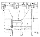
- the single drawing figure shows a diagram showing the time course of certain variables when using the method according to the invention, using the example of a spot welding device (welding gun), which additionally illustrates the essential parts (electrodes) in different working phases.
- spot welding device welding gun
- a counter electrode 2 In a first working phase, the so-called compensation stroke (movement 1 between time t 0 and t 1 ), a counter electrode 2 is moved from a rear side against a merely indicated workpiece 4 (usually two sheets to be joined).
- the contact pressure F is crucial for the quality of the connection. Due to the invention, therefore, the contact pressure F is controlled automatically for each joining operation to a predetermined optimum value.
- an electric drive is used according to the invention, so that an electric current i can be used as a measured variable.
- a specific working current i A can be determined.
- the associated travel current i F is determined for the stroke movement of the working electrode 6 at an actually arbitrary but constant travel speed.
- a speed n of the drive can be detected. It can then be determined in each subsequent working stroke (movement 2) dependent on the operating conditions change of a system size, and then according to the ratio of this change in size for the respective working phase and the relevant for the contact force F working current i A.
- either the driving speed or speed n can be kept constant by a specific change of the current i F and the adjustment of the working current i A can be made on the basis of the current change, or it can be a constant speed of the current i F a change in the speed n as a measure of the required change of i A will be evaluated.
- an electric linear motor can be used. It may be an electric rotary motor with downstream drive means, the rotational movement of the motor in a linear drive movement for the electrode. 6 implement.
- drive means for example, a spindle drive (ball screw) is suitable.
Landscapes
- Engineering & Computer Science (AREA)
- Mechanical Engineering (AREA)
- Robotics (AREA)
- Resistance Welding (AREA)
- Pressure Welding/Diffusion-Bonding (AREA)
Abstract
Description
Die vorliegende Erfindung betrifft ein Verfahren zum Steuern einer Werkzeug-Anpreßkraft eines Arbeitswerkzeuges bei Fügevorrichtungen, wie Schweißzangen, Durchsetzfügevorrichtungen und dergleichen gemäβ dem Oberbegriffen der Ansprüche 1 und 2.
Des Weiteren betrifft die vorliegende Erfindung eine Fügevorrichtung gemäß dem Oberbegriff des Anspruchs 5.The present invention relates to a method for controlling a tool pressing force of a working tool in joining devices such as welding guns, clinching devices and the like according to the preambles of
Furthermore, the present invention relates to a joining device according to the preamble of claim 5.
Es ist bekannt, Werkstücke, insbesondere Bleche, miteinander thermisch und stoffschlüssig durch Punktschweißen zu verbinden. Dazu werden Schweißzangen verwendet, die jeweils als Arbeitswerkzeug eine Arbeitselektrode aufweisen, wobei die Bleche zwischen der Arbeitselektrode und einer Gegenelektrode verschweißt werden. Weiterhin sind auch andere (Punkt-) Fügeverfahren bekannt, wie beispielsweise das sogenannte Durchsetzfügen, wie es auch unter dem Begriff "Toxen" bekannt ist. Dabei sind ein Arbeitswerkzeug als Druckstempel und ein Gegenwerkzeug als Gegenstempel ausgebildet, zwischen denen Bleche mechanisch durch topfartige Prägepunkte form- oder kraftformschlüssig verbunden werden können.It is known to connect workpieces, in particular sheets, to each other thermally and cohesively by spot welding. For this purpose, welding guns are used, each having a working electrode as a working tool, wherein the sheets are welded between the working electrode and a counter electrode. Furthermore, other (point) joining methods are known, such as the so-called clinching, as it is also known under the term "toxins". In this case, a working tool as a plunger and a counter tool are formed as a counter punch, between which sheets mechanically by pot-shaped embossing points form-fitting or kraftformschlüssig can be connected.
Für eine spezielle Widerstandschweißmaschine ist der mechanische Aufbau aus der Druckschrift FR 2 585 976 bekannt. Dort wird die Annäherungsgeschwindigkeit und die Anpreßkraft einer beweglichen Elektrode über einen offenen (Steuerung) oder geschlossenen Regelkreis während des gesamten Fügevorgangs eingestellt.For a special resistance welding machine, the mechanical structure of the
In allen Fällen hängt die Qualität der Fügeverbindungen stark von der Anpreßkraft des jeweiligen Arbeitswerkzeugs (Elektrode, Stempel oder dergleichen) ab. In der Praxis hat sich gezeigt, dass unter wechselnden Betriebsbedingungen die Qualität der Fügeverbindungen stark variieren kann, so dass es später sogar zu Trennungen der Verbindungen kommen kann.In all cases, the quality of the joints greatly depends on the contact pressure of the respective working tool (electrode, stamp or the like). In practice, it has been found that under varying operating conditions, the quality of the joints can vary greatly, so that it can even lead to separations of the compounds later.
Der vorliegenden Erfindung liegt die Aufgabe zugrunde, ein Verfahren zum Steuern der Werkzeug-Anpreßkraft für Fügevorrichtungen der genannten Art anzugeben, mit dem stets und auch weitgehend unabhängig von wechselnden Betriebsbedingungen eine hohe Fügequalität und- sicherheit gewährleistet werden kann.The present invention has for its object to provide a method for controlling the tool pressing force for joining devices of the type mentioned, with the always and also largely independent of changing operating conditions high joint quality and safety can be ensured.
Erfindungsgemäß wird dies durch ein Verfahren gemäß Anspruch 1 oder Anspruch 2 und eine Fügevorrichtung gemäß dem Anspruch 5 erreicht, wobei ein elektrischer Antrieb verwendet wird, um einerseits das Arbeitswerkzeug über einen Arbeitshub gegen ein Werkstück zu bewegen und andererseits auch anschließend bei Werkstück-Kontakt mit der Anpreßkraft zu beaufschlagen. Dabei werden in einer ersten Variante der Erfindung zum Steuern der Anpreßkraft folgende Schritte durchgeführt:According to the invention this is achieved by a method according to claim 1 or claim 2 and a joining device according to claim 5, wherein an electric drive is used, on the one hand to move the working tool over a working stroke against a workpiece and on the other hand also in workpiece contact with the To apply pressing force. In a first variant of the invention, the following steps are carried out to control the contact pressure:
Einleitend wird zunächst einmalig eine gewünschte Soll-Anpreßkraft des Arbeitswerkzeugs festgelegt, und es wird mit geeigneten Mitteln ein dazu erforderlicher Arbeitsstrom für den elektrischen Antrieb ermittelt. Etwa zeitgleich dazu, also unmittelbar zeitlich davor oder danach - und dadurch praktisch bei den gleichen Betriebsbedingungen - wird ein bestimmter Fahrstrom des elektrischen Antriebs für eine einmal festgelegte, eigentlich beliebige, aber konstante Fahrgeschwindigkeit für die Hubbewegung, insbesondere für den eigentlichen Arbeitshub, ermittelt. Nachfolgend wird bei späteren Hubbewegungen, insbesondere in jedem späteren Arbeitshub, die tatsächliche Fahrgeschwindigkeit überwacht und erforderlichenfalls, wenn die Ist-Geschwindigkeit von der zuvor ermittelten konstanten Fahrgeschwindigkeit abweicht, durch eine entsprechende Änderung des Fahrstroms wieder auf die konstante Fahrgeschwindigkeit gebracht, d. h. die Fahrgeschwindigkeit wird durch Anpassung des Fahrstromes konstant gehalten, wobei die dazu erforderliche Stromänderung ermittelt wird. Wenn dann anschließend das Arbeitswerkzeug zum Anlagekontakt am jeweiligen Werkstück kommt, so wird in Abhängigkeit von der zuvor ermittelten Stromänderung auch der Arbeitsstrom in einem entsprechenden Verhältnis geändert, wodurch dann die daraus resultierende Anpreßkraft dem Soll-Wert entspricht.Initially, a desired setpoint contact pressure of the work tool is initially set once, and it is determined by suitable means a working current required for the electric drive. At about the same time, ie immediately before or after it - and thus practically under the same operating conditions - a certain traction current of the electric drive for a once fixed, actually arbitrary, but constant travel speed for the lifting movement, in particular for the actual working stroke, determined. Subsequently, in later strokes, in particular in each subsequent stroke, the actual driving speed is monitored and, if necessary, when the actual speed deviates from the previously determined constant driving speed, brought by a corresponding change in the driving current back to the constant driving speed, d. H. the driving speed is kept constant by adjusting the traction current, whereby the required current change is determined. If then then the working tool comes into abutting contact with the respective workpiece, so the working current is changed in a corresponding ratio, depending on the previously determined current change, whereby then the resulting contact pressure corresponds to the desired value.
Die Erfindung beruht somit auf der Erkenntnis, dass verschiedene Betriebsbedingungen, wie z. B. unterschiedliche Temperaturen, Verschmutzungen insbesondere in Lagerbereichen, schwerkraft- und raumlageabhängige Belastungen u.s.w., auch zu unterschiedlichen Fahrgeschwindigkeiten während der Hubbewegungen sowie dann aber auch zu entsprechenden Abweichungen der Anpreßkraft vom gewünschten optimalen Soll-Wert führen. Beispielsweise führen unterschiedliche Umgebungstemperaturen zur Änderungen von Reibwerten im System und zu Viskositätsänderungen von Schmiermitteln, was sich dann insgesamt durch unterschiedliche Fahrgeschwindigkeiten bemerkbar macht. Die Hubbewegung insbesondere im eigentlichen Arbeitshub wird daher erfindungsgemäß als "Meßfahrt" genutzt, um anhand einer sich ändemden Geschwindigkeit alle dafür maßgeblichen Einflüsse zu erfassen und dann zu kompensieren.The invention is thus based on the finding that various operating conditions, such. As different temperatures, soiling especially in storage areas, gravity and space-dependent loads, etc., also lead to different speeds during the strokes and then but also to corresponding deviations of the contact pressure of the desired optimum target value. For example, different ambient temperatures lead to changes in the coefficients of friction in the system and changes in the viscosity of lubricants, which then manifests itself as a result of different speeds of travel. The lifting movement, in particular in the actual working stroke, is therefore used according to the invention as a "measuring run", in order to record and then compensate for all relevant influences on the basis of a changing speed.
Eine entsprechende Messfahrt kann jedoch auch außerhalb des eigentlichen Arbeitshubes durch eine zusätzliche (spezielle) Hubbewegung durchgeführt werden. Zudem kann eine Anpassung der Anpresskraft an veränderte Bedingungen auch in zeitlich festgelegten Intervallen (z. B. nach jedem neuen Werkstück) jeweils durch eine spezielle Messfahrt durchgeführt werden.However, a corresponding measuring run can also be carried out outside the actual working stroke by means of an additional (special) lifting movement. In addition, an adaptation of the contact pressure to changing conditions can also be carried out at timed intervals (eg after each new workpiece) by means of a special measuring run.
Die erfindungsgemäße Kraftsteuerung erfolgt somit bei einer ersten Ausführungsart der Erfindung (Anspruch 1) durch Konstanthalten der Fahrgeschwindigkeit und Ermittlung einer dafür notwendigen Stromänderung, wobei dann im Verhältnis der Fahrstromänderung auch der Arbeitsstrom geändert wird.The power control according to the invention thus takes place in a first embodiment of the invention (claim 1) by keeping constant the driving speed and determining a necessary change in current, in which case the working current is changed in proportion to the traction current change.
In einer Ausführungsvariante der Erfindung kann auch bei jeder Hubbewegung der Fahrstrom konstant auf einem ursprünglich festgelegten, während der ersten "Referenzfahrt" einer bestimmten Fahrgeschwindigkeit entsprechenden Wert gehalten werden, wobei während jeder späteren, als Meßfahrt genutzten Hubbewegung eine gegenüber der zuvor bestimmten Fahrgeschwindigkeit auftretende Geschwindigkeitsänderung als Maß für die anschließende Anpassung des Arbeitsstroms ausgewertet wird (Anspruch 2).In one embodiment of the invention, the traction current can be kept constant at an originally determined, during the first "reference travel" of a certain driving speed value, wherein during each later, used as a measuring travel stroke movement compared to the previously determined driving speed occurring speed change as Measured for the subsequent adjustment of the working flow is evaluated (claim 2).
In allen Fällen kann zweckmäßigerweise die Fahrgeschwindigkeit indirekt über eine Drehzahlmessung des elektrischen Antriebs ermittelt werden.In all cases, the driving speed can be determined indirectly indirectly via a rotational speed measurement of the electric drive.
Anhand der Zeichnung soll die Erfindung beispielhaft noch genauer erläutert werden. Die einzige Zeichnungsfigur zeigt ein Diagramm mit Darstellung des zeitlichen Verlaufs bestimmter Größen bei Anwendung des erfindungsgemäßen Verfahrens am Beispiels einer Punktschweißvorrichtung (Schweißzange), von der zusätzlich die wesentlichen Teile (Elektroden) in verschiedenen Arbeitsphasen veranschaulicht sind.Reference to the drawing, the invention will be explained in more detail by way of example. The single drawing figure shows a diagram showing the time course of certain variables when using the method according to the invention, using the example of a spot welding device (welding gun), which additionally illustrates the essential parts (electrodes) in different working phases.
In einer ersten Arbeitsphase, dem sogenannten Ausgleichshub (Bewegung 1 zwischen Zeitpunkt t0 und t1) wird eine Gegenelektrode 2 von einer Rückseite gegen ein lediglich angedeutetes Werkstück 4 (in der Regel zwei zu verbindende Bleche) bewegt. Zeitgleich beginnt auf der gegenüberliegenden Vorderseite die Bewegung einer Arbeitselektrode 6 über einen Arbeitshub gegen das Werkstück 4 (siehe Bewegung 2 von t1 bis t2), und dann erfolgt ab dem Zeitpunkt t2 bei Elektroden-Anlage (Geschwindigkeit der Elektrode 6 relativ zum Werkstück 4 = Null, relativ zu Zangenarmen der Schweißzange wegen Durchbiegen der Arme aber erst noch bis zum Zeitpunkt t3 bis auf Null abnehmend) ein Kraftaufbau, um den Füge- bzw. Schweißvorgang bis t4 unter einer bestimmten Anpreßkraft F durchzuführen. Die Anpreßkraft F ist für die Qualität der Verbindung entscheidend. Durch die Erfindung wird deshalb die Anpreßkraft F selbsttätig für jeden Fügevorgang auf einen vorgegebenen optimalen Wert gesteuert.In a first working phase, the so-called compensation stroke (
Zum Antrieb zumindest der Arbeitselektrode 6 wird erfindungsgemäß ein elektrischer Antrieb verwendet, so dass ein elektrischer Strom i als Meßgröße genutzt werden kann. So kann für eine einmal festgelegte, optimale Anpreßkraft F ein bestimmter Arbeitsstrom iA ermittelt werden. Etwa zeitgleich, d. h. unmittelbar danach oder auch davor, also praktisch unter den selben Betriebsbedingungen, wird für die Hubbewegung der Arbeitselektrode 6 bei einer eigentlich beliebigen, aber konstanten Fahrgeschwindigkeit der zugehörige Fahrstrom iF ermittelt. Als Maß für die Fahrgeschwindigkeit kann eine Drehzahl n des Antriebs erfaßt werden. Es kann dann vorzugsweise in jedem späteren Arbeitshub (Bewegung 2) eine von den Betriebsbedingungen abhängige Änderung einer Systemgröße festgestellt werden, um dann entsprechend dem Verhältnis dieser Größenänderung für die jeweilige Arbeitsphase auch den für die Anpreßkraft F maßgeblichen Arbeitsstrom iA anzupassen. Dazu kann wahlweise entweder die Fahrgeschwindigkeit bzw. Drehzahl n durch eine bestimmte Änderung des Stromes iF konstant gehalten und die Anpassung des Arbeitsstroms iA anhand der Stromänderung vorgenommen werden, oder es kann bei konstantem Fahrstrom iF eine Änderung der Geschwindigkeit n als Maß für die erforderliche Änderung von iA ausgewertet werden.For driving at least the working
Als elektrischer Antrieb kann ein Elektro-Linearmotor verwendet werden. Es kann sich um einen Elektro-Rotationsmotor mit nachgeschalteten Antriebsmitteln handeln, die die Rotationsbewegung des Motors in eine lineare Antriebsbewegung für die Elektrode 6 umsetzen. Als Antriebsmittel ist beispielsweise ein Spindeltrieb (Kugelspindel) geeignet.As electric drive, an electric linear motor can be used. It may be an electric rotary motor with downstream drive means, the rotational movement of the motor in a linear drive movement for the electrode. 6 implement. As drive means, for example, a spindle drive (ball screw) is suitable.
Durch die Erfindung können auf sehr einfache, aber wirkungsvolle Weise zumindest die folgenden Einflußgrößen kompensiert werden:
- Viskosität des Schmierstoffes in Abhängigkeit von Temperatur und Alterung
- Reibwert der Antriebsmittel bei unterschiedlichen Temperaturen
- mechanische Wirkungsgradänderung in Abhängigkeit von der Hubanzahl
- Führungen und Lagerungen der Antriebsmittel in Abhängigkeit von den Hubanzahlen
- Führungen und Lagerungen der Vorrichtung in Abhängigkeit von Hubzahlen, Verschmutzungen und Temperatur
- weitere mechanische Größen, die sich durch Temperatur und/oder Hubzahlen verändern
- externe Einflüsse, insbesondere Schwerkrafteinfluß, durch unterschiedliche Lage und Gewichtsänderungen der Fügevorrichtung (insbesondere bei großen Schweißzangen, vor allem sogenannten X-Zangen mit entsprechend schweren Armen).
- Viscosity of the lubricant as a function of temperature and aging
- Friction coefficient of the drive means at different temperatures
- mechanical efficiency change as a function of the number of strokes
- Guides and bearings of the drive means as a function of the Hubanzahlen
- Guides and bearings of the device as a function of stroke rates, contamination and temperature
- other mechanical variables that change due to temperature and / or stroke rates
- external influences, in particular the influence of gravity, by different position and weight changes of the joining device (especially in large welding tongs, especially so-called X-tongs with correspondingly heavy arms).
Die Erfindung ist nicht auf die konkret beschriebenen Varianten und Anwendungsbeispiele beschränkt, sondern umfaßt die durch die Ansprüche definierten Ausführungen und Anwendungen.The invention is not limited to the specifically described variants and application examples, but includes the embodiments and applications defined by the claims.
Claims (7)
- A process for controlling a tool pressure force (F) of an operating tool (6) in joining devices, such as welding tongs, clinching devices and the like, in which an electric drive moves the operating tool (6) against a workpiece by way of a drive stroke and, with workpiece contact, the operating tool is then acted upon by the pressure force (F), characterised in that the following steps are carried out for controlling the pressure force (F):a) specifying a set pressure force (F) and determining the necessary operating current (iA) for this for the electric drive; andb) specifying any set travelling speed for the stroke movement of the operating tool (6) and determining an associated traction current (iF) for the electric drive;c) for later stroke movements, particularly in each further operating stroke, comparing the actual travelling speed with the set travelling speed and carrying out the necessary adaptation to the set travelling speed by altering the traction current (iF) accordingly; andd) with workpiece contact, adapting the operating current (iA) according to the change in the traction current (iF).
- A process for controlling a tool pressure force (F) of an operating tool (6) in joining devices such as welding tongs, clinching devices and the like, in which an electric drive moves the operating tool (6) against a workpiece by way of a drive stroke and, with workpiece contact, the operating tool is then acted upon by the pressure force (F), characterised in that the following steps are carried out for controlling the pressure force (F):a) specifying a set pressure force (F) and determining the necessary operating current (iA) for this for the electric drive; andb) specifying a particular constant traction current (iF) for the electric drive with any travelling speed of the stroke movement;c) in later stroke movements, particularly in each further operating stroke, measuring the actual travelling speed for the constant traction current (iF) and determining a possible change in speed; andd) with workpiece contact, adapting the operating current (iA) according to the determined change in the traction current (iF) .
- A process according to Claim 1 or 2, characterised in that the operating current (iA) is altered proportionally to the ratio of the determined change in the traction current (iF) or speed.
- A process according to one of Claims 1 to 3, characterised in that the travelling speed is determined indirectly by measuring the speed (n) of the electric drive.
- A joining device for producing join connections in workpieces, particularly welding tongs, a clinching device or the like, having an operating tool (6) and a counter tool (2), in which the operating tool (6) is movable in the direction of the counter tool (2) and against a workpiece (4) by way of an operating stroke and, with workpiece contact, can be acted upon by a pressure force (F), an electric drive being provided for driving the operating tool (6) and applying the pressure force (F), characterised by a device for measuring the travelling speed of the operating tool (6) during the stroke movement, a device for measuring the electrical current (i) of the electric drive, storage means for storing changes in the current (i) with respect to a traction current (iF) associated with any specified set travelling speed of the stroke movement and/or for storing changes in the speed (n) of the stroke movement with respect to a travelling speed associated with a specified, constant traction current and by an evaluating unit for adapting the operating current (iA) according to the stored changes.
- A joining device according to Claim 5, characterised in that, for the indirect measurement of the travelling speed of the operating tool (6), means are provided for measuring the speed (n) of the electric drive.
- A joining device according to Claim 5 or 6, characterised by means for measuring the pressure force (F) of the operating tool (6) and for determining an associated operating current (iA) .
Applications Claiming Priority (2)
| Application Number | Priority Date | Filing Date | Title |
|---|---|---|---|
| DE10258059 | 2002-12-11 | ||
| DE10258059A DE10258059B4 (en) | 2002-12-11 | 2002-12-11 | Method for controlling a tool pressing force in joining devices |
Publications (2)
| Publication Number | Publication Date |
|---|---|
| EP1428608A1 EP1428608A1 (en) | 2004-06-16 |
| EP1428608B1 true EP1428608B1 (en) | 2006-04-05 |
Family
ID=30010650
Family Applications (1)
| Application Number | Title | Priority Date | Filing Date |
|---|---|---|---|
| EP03027937A Expired - Lifetime EP1428608B1 (en) | 2002-12-11 | 2003-12-04 | Method of controlling the pressing force of a tool of a joining device and such joining device |
Country Status (4)
| Country | Link |
|---|---|
| EP (1) | EP1428608B1 (en) |
| AT (1) | ATE322356T1 (en) |
| DE (3) | DE10258059B4 (en) |
| ES (1) | ES2256655T3 (en) |
Cited By (2)
| Publication number | Priority date | Publication date | Assignee | Title |
|---|---|---|---|---|
| DE102007062375A1 (en) | 2007-12-22 | 2009-06-25 | Volkswagen Ag | Spot-welding process used in automobile industry, first heats, softens and deforms weld location to eliminate dimensional and location errors, before applying full welding current and pressure |
| EP2105237A2 (en) | 2007-05-07 | 2009-09-30 | Nimak GmbH | Method for operating an electrode pressure unit for a welding clamp and corresponding welding clamp |
Families Citing this family (1)
| Publication number | Priority date | Publication date | Assignee | Title |
|---|---|---|---|---|
| JP6904479B2 (en) * | 2018-11-08 | 2021-07-14 | Jfeスチール株式会社 | Resistance spot welding method and welding member manufacturing method |
Family Cites Families (4)
| Publication number | Priority date | Publication date | Assignee | Title |
|---|---|---|---|---|
| FR2585976B1 (en) * | 1985-08-09 | 1992-05-15 | Aro | NUMERICALLY CONTROLLED RESISTANCE WELDING MACHINE AND SCREW AND NUT SYSTEM OR THE LIKE |
| JP2732159B2 (en) * | 1991-10-29 | 1998-03-25 | ファナック株式会社 | Abnormal load detection method |
| FR2728820A1 (en) * | 1994-12-30 | 1996-07-05 | Renault | RESISTANCE WELDING DEVICE WITH EFFORT CONTROL |
| DE19738647A1 (en) * | 1997-09-04 | 1999-03-25 | Messer Griesheim Schweistechni | Resistance pressure welding machine |
-
2002
- 2002-12-11 DE DE10258059A patent/DE10258059B4/en not_active Expired - Fee Related
-
2003
- 2003-10-02 DE DE20315201U patent/DE20315201U1/en not_active Expired - Lifetime
- 2003-12-04 EP EP03027937A patent/EP1428608B1/en not_active Expired - Lifetime
- 2003-12-04 AT AT03027937T patent/ATE322356T1/en active
- 2003-12-04 DE DE50302883T patent/DE50302883D1/en not_active Expired - Lifetime
- 2003-12-04 ES ES03027937T patent/ES2256655T3/en not_active Expired - Lifetime
Cited By (3)
| Publication number | Priority date | Publication date | Assignee | Title |
|---|---|---|---|---|
| EP2105237A2 (en) | 2007-05-07 | 2009-09-30 | Nimak GmbH | Method for operating an electrode pressure unit for a welding clamp and corresponding welding clamp |
| DE102007062375A1 (en) | 2007-12-22 | 2009-06-25 | Volkswagen Ag | Spot-welding process used in automobile industry, first heats, softens and deforms weld location to eliminate dimensional and location errors, before applying full welding current and pressure |
| DE102007062375A8 (en) * | 2007-12-22 | 2013-12-12 | Volkswagen Ag | Method for resistance welding of components |
Also Published As
| Publication number | Publication date |
|---|---|
| DE10258059A1 (en) | 2004-07-22 |
| ATE322356T1 (en) | 2006-04-15 |
| DE50302883D1 (en) | 2006-05-18 |
| DE20315201U1 (en) | 2003-12-24 |
| EP1428608A1 (en) | 2004-06-16 |
| DE10258059B4 (en) | 2006-12-14 |
| ES2256655T3 (en) | 2006-07-16 |
Similar Documents
| Publication | Publication Date | Title |
|---|---|---|
| EP1409190B1 (en) | Resistance welding device and control method | |
| DE102006056051B4 (en) | Robot with control for additional axes | |
| DE4206584C2 (en) | Device and method for connecting two components by means of ultrasound | |
| DE102006014068A1 (en) | Apparatus and method for clamping sheet metal components | |
| DE102011087958A1 (en) | welding robots | |
| EP2485108A2 (en) | Method for referencing an actuator position of at least one electric actuator | |
| EP1508396A1 (en) | Method and device for controlling welding pressure of a welding gun | |
| DE3439096C2 (en) | ||
| DE60317987T2 (en) | Spot welding device and method for controlling the pressing force of a welding gun | |
| EP3639963B1 (en) | Device and method for operating a resistance welding device | |
| EP1428608B1 (en) | Method of controlling the pressing force of a tool of a joining device and such joining device | |
| DE102008039872A1 (en) | Resistance welding arrangement | |
| EP3680050A2 (en) | Method for testing welding tongs for resistance welding of workpieces | |
| DE10354526A1 (en) | Industrial robot with multi-axis movement for friction welding of components has a friction welding unit whose individual actions are controled via an additional control line linked to robot control unit | |
| DE10127112A1 (en) | welding head | |
| DE10247438B4 (en) | Method and device for welding workpieces | |
| EP3233359A1 (en) | Method and system for calibrating the tong pressing force of an automatically actuatable pair of manufacturing tongs | |
| EP1990122B9 (en) | Method for operating an electrode pressure unit for a welding clamp and corresponding welding clamp | |
| DE102008062979A1 (en) | Method for positioning a tool holder on a workpiece, comprises positioning a tool on the workpiece holder under use of a drive unit driven by a sensor-less motor, by moving the workpiece holder relative to workpiece | |
| EP2072171B1 (en) | Device for processing workpieces | |
| EP3822014A1 (en) | Method for scanning the surface of metallic workpieces | |
| EP3854510B1 (en) | Welding control device and method for validating force values in the control of a welding tool | |
| DE202016107208U1 (en) | Heizelementschweißeinheit | |
| DE102017214025B4 (en) | Clamping tool for clamping together sheets to be welded by means of laser welding and the associated process | |
| EP4313519A1 (en) | System and method for executing an assembly task by means of a robot |
Legal Events
| Date | Code | Title | Description |
|---|---|---|---|
| PUAI | Public reference made under article 153(3) epc to a published international application that has entered the european phase |
Free format text: ORIGINAL CODE: 0009012 |
|
| AK | Designated contracting states |
Kind code of ref document: A1 Designated state(s): AT BE BG CH CY CZ DE DK EE ES FI FR GB GR HU IE IT LI LU MC NL PT RO SE SI SK TR |
|
| AX | Request for extension of the european patent |
Extension state: AL LT LV MK |
|
| 17P | Request for examination filed |
Effective date: 20040626 |
|
| 17Q | First examination report despatched |
Effective date: 20040819 |
|
| AKX | Designation fees paid |
Designated state(s): AT BE BG CH CY CZ DE DK EE ES FI FR GB GR HU IE IT LI LU MC NL PT RO SE SI SK TR |
|
| GRAP | Despatch of communication of intention to grant a patent |
Free format text: ORIGINAL CODE: EPIDOSNIGR1 |
|
| GRAS | Grant fee paid |
Free format text: ORIGINAL CODE: EPIDOSNIGR3 |
|
| GRAA | (expected) grant |
Free format text: ORIGINAL CODE: 0009210 |
|
| AK | Designated contracting states |
Kind code of ref document: B1 Designated state(s): AT BE BG CH CY CZ DE DK EE ES FI FR GB GR HU IE IT LI LU MC NL PT RO SE SI SK TR |
|
| PG25 | Lapsed in a contracting state [announced via postgrant information from national office to epo] |
Ref country code: FI Free format text: LAPSE BECAUSE OF FAILURE TO SUBMIT A TRANSLATION OF THE DESCRIPTION OR TO PAY THE FEE WITHIN THE PRESCRIBED TIME-LIMIT Effective date: 20060405 Ref country code: RO Free format text: LAPSE BECAUSE OF FAILURE TO SUBMIT A TRANSLATION OF THE DESCRIPTION OR TO PAY THE FEE WITHIN THE PRESCRIBED TIME-LIMIT Effective date: 20060405 Ref country code: NL Free format text: LAPSE BECAUSE OF FAILURE TO SUBMIT A TRANSLATION OF THE DESCRIPTION OR TO PAY THE FEE WITHIN THE PRESCRIBED TIME-LIMIT Effective date: 20060405 Ref country code: GB Free format text: LAPSE BECAUSE OF FAILURE TO SUBMIT A TRANSLATION OF THE DESCRIPTION OR TO PAY THE FEE WITHIN THE PRESCRIBED TIME-LIMIT Effective date: 20060405 Ref country code: CZ Free format text: LAPSE BECAUSE OF FAILURE TO SUBMIT A TRANSLATION OF THE DESCRIPTION OR TO PAY THE FEE WITHIN THE PRESCRIBED TIME-LIMIT Effective date: 20060405 Ref country code: SI Free format text: LAPSE BECAUSE OF FAILURE TO SUBMIT A TRANSLATION OF THE DESCRIPTION OR TO PAY THE FEE WITHIN THE PRESCRIBED TIME-LIMIT Effective date: 20060405 Ref country code: SK Free format text: LAPSE BECAUSE OF FAILURE TO SUBMIT A TRANSLATION OF THE DESCRIPTION OR TO PAY THE FEE WITHIN THE PRESCRIBED TIME-LIMIT Effective date: 20060405 Ref country code: IE Free format text: LAPSE BECAUSE OF FAILURE TO SUBMIT A TRANSLATION OF THE DESCRIPTION OR TO PAY THE FEE WITHIN THE PRESCRIBED TIME-LIMIT Effective date: 20060405 |
|
| REG | Reference to a national code |
Ref country code: GB Ref legal event code: FG4D Free format text: NOT ENGLISH |
|
| REG | Reference to a national code |
Ref country code: CH Ref legal event code: EP |
|
| REG | Reference to a national code |
Ref country code: IE Ref legal event code: FG4D Free format text: LANGUAGE OF EP DOCUMENT: GERMAN |
|
| REF | Corresponds to: |
Ref document number: 50302883 Country of ref document: DE Date of ref document: 20060518 Kind code of ref document: P |
|
| PG25 | Lapsed in a contracting state [announced via postgrant information from national office to epo] |
Ref country code: SE Free format text: LAPSE BECAUSE OF FAILURE TO SUBMIT A TRANSLATION OF THE DESCRIPTION OR TO PAY THE FEE WITHIN THE PRESCRIBED TIME-LIMIT Effective date: 20060705 Ref country code: DK Free format text: LAPSE BECAUSE OF FAILURE TO SUBMIT A TRANSLATION OF THE DESCRIPTION OR TO PAY THE FEE WITHIN THE PRESCRIBED TIME-LIMIT Effective date: 20060705 |
|
| REG | Reference to a national code |
Ref country code: ES Ref legal event code: FG2A Ref document number: 2256655 Country of ref document: ES Kind code of ref document: T3 |
|
| PG25 | Lapsed in a contracting state [announced via postgrant information from national office to epo] |
Ref country code: PT Free format text: LAPSE BECAUSE OF FAILURE TO SUBMIT A TRANSLATION OF THE DESCRIPTION OR TO PAY THE FEE WITHIN THE PRESCRIBED TIME-LIMIT Effective date: 20060905 |
|
| ET | Fr: translation filed | ||
| NLV1 | Nl: lapsed or annulled due to failure to fulfill the requirements of art. 29p and 29m of the patents act | ||
| GBV | Gb: ep patent (uk) treated as always having been void in accordance with gb section 77(7)/1977 [no translation filed] |
Effective date: 20060405 |
|
| REG | Reference to a national code |
Ref country code: IE Ref legal event code: FD4D |
|
| PG25 | Lapsed in a contracting state [announced via postgrant information from national office to epo] |
Ref country code: MC Free format text: LAPSE BECAUSE OF NON-PAYMENT OF DUE FEES Effective date: 20061231 Ref country code: BE Free format text: LAPSE BECAUSE OF NON-PAYMENT OF DUE FEES Effective date: 20061231 |
|
| PLBE | No opposition filed within time limit |
Free format text: ORIGINAL CODE: 0009261 |
|
| STAA | Information on the status of an ep patent application or granted ep patent |
Free format text: STATUS: NO OPPOSITION FILED WITHIN TIME LIMIT |
|
| 26N | No opposition filed |
Effective date: 20070108 |
|
| BERE | Be: lapsed |
Owner name: NIMAK AUTOMATISIERTE SCHWEISSTECHNIK G.M.B.H. Effective date: 20061231 |
|
| PG25 | Lapsed in a contracting state [announced via postgrant information from national office to epo] |
Ref country code: GR Free format text: LAPSE BECAUSE OF FAILURE TO SUBMIT A TRANSLATION OF THE DESCRIPTION OR TO PAY THE FEE WITHIN THE PRESCRIBED TIME-LIMIT Effective date: 20060706 |
|
| PG25 | Lapsed in a contracting state [announced via postgrant information from national office to epo] |
Ref country code: BG Free format text: LAPSE BECAUSE OF FAILURE TO SUBMIT A TRANSLATION OF THE DESCRIPTION OR TO PAY THE FEE WITHIN THE PRESCRIBED TIME-LIMIT Effective date: 20060705 Ref country code: EE Free format text: LAPSE BECAUSE OF FAILURE TO SUBMIT A TRANSLATION OF THE DESCRIPTION OR TO PAY THE FEE WITHIN THE PRESCRIBED TIME-LIMIT Effective date: 20060405 |
|
| PG25 | Lapsed in a contracting state [announced via postgrant information from national office to epo] |
Ref country code: LU Free format text: LAPSE BECAUSE OF NON-PAYMENT OF DUE FEES Effective date: 20061204 Ref country code: HU Free format text: LAPSE BECAUSE OF FAILURE TO SUBMIT A TRANSLATION OF THE DESCRIPTION OR TO PAY THE FEE WITHIN THE PRESCRIBED TIME-LIMIT Effective date: 20061006 Ref country code: TR Free format text: LAPSE BECAUSE OF FAILURE TO SUBMIT A TRANSLATION OF THE DESCRIPTION OR TO PAY THE FEE WITHIN THE PRESCRIBED TIME-LIMIT Effective date: 20060405 |
|
| REG | Reference to a national code |
Ref country code: CH Ref legal event code: PL |
|
| PG25 | Lapsed in a contracting state [announced via postgrant information from national office to epo] |
Ref country code: CH Free format text: LAPSE BECAUSE OF NON-PAYMENT OF DUE FEES Effective date: 20071231 Ref country code: LI Free format text: LAPSE BECAUSE OF NON-PAYMENT OF DUE FEES Effective date: 20071231 |
|
| PG25 | Lapsed in a contracting state [announced via postgrant information from national office to epo] |
Ref country code: CY Free format text: LAPSE BECAUSE OF FAILURE TO SUBMIT A TRANSLATION OF THE DESCRIPTION OR TO PAY THE FEE WITHIN THE PRESCRIBED TIME-LIMIT Effective date: 20060405 |
|
| PGFP | Annual fee paid to national office [announced via postgrant information from national office to epo] |
Ref country code: AT Payment date: 20131126 Year of fee payment: 11 |
|
| PGFP | Annual fee paid to national office [announced via postgrant information from national office to epo] |
Ref country code: IT Payment date: 20131206 Year of fee payment: 11 Ref country code: FR Payment date: 20131209 Year of fee payment: 11 Ref country code: ES Payment date: 20131127 Year of fee payment: 11 |
|
| PGFP | Annual fee paid to national office [announced via postgrant information from national office to epo] |
Ref country code: DE Payment date: 20140227 Year of fee payment: 11 |
|
| REG | Reference to a national code |
Ref country code: DE Ref legal event code: R119 Ref document number: 50302883 Country of ref document: DE |
|
| REG | Reference to a national code |
Ref country code: AT Ref legal event code: MM01 Ref document number: 322356 Country of ref document: AT Kind code of ref document: T Effective date: 20141204 |
|
| REG | Reference to a national code |
Ref country code: FR Ref legal event code: ST Effective date: 20150831 |
|
| PG25 | Lapsed in a contracting state [announced via postgrant information from national office to epo] |
Ref country code: DE Free format text: LAPSE BECAUSE OF NON-PAYMENT OF DUE FEES Effective date: 20150701 |
|
| PG25 | Lapsed in a contracting state [announced via postgrant information from national office to epo] |
Ref country code: AT Free format text: LAPSE BECAUSE OF NON-PAYMENT OF DUE FEES Effective date: 20141204 Ref country code: FR Free format text: LAPSE BECAUSE OF NON-PAYMENT OF DUE FEES Effective date: 20141231 |
|
| PG25 | Lapsed in a contracting state [announced via postgrant information from national office to epo] |
Ref country code: IT Free format text: LAPSE BECAUSE OF NON-PAYMENT OF DUE FEES Effective date: 20141204 |
|
| REG | Reference to a national code |
Ref country code: ES Ref legal event code: FD2A Effective date: 20160128 |
|
| PG25 | Lapsed in a contracting state [announced via postgrant information from national office to epo] |
Ref country code: ES Free format text: LAPSE BECAUSE OF NON-PAYMENT OF DUE FEES Effective date: 20141205 |