EP1399091B1 - Stent with optimal strength and radio-opacity characteristics - Google Patents
Stent with optimal strength and radio-opacity characteristics Download PDFInfo
- Publication number
- EP1399091B1 EP1399091B1 EP01968924.9A EP01968924A EP1399091B1 EP 1399091 B1 EP1399091 B1 EP 1399091B1 EP 01968924 A EP01968924 A EP 01968924A EP 1399091 B1 EP1399091 B1 EP 1399091B1
- Authority
- EP
- European Patent Office
- Prior art keywords
- stent
- strut members
- sets
- links
- strut
- Prior art date
- Legal status (The legal status is an assumption and is not a legal conclusion. Google has not performed a legal analysis and makes no representation as to the accuracy of the status listed.)
- Expired - Lifetime
Links
Images


Classifications
-
- A—HUMAN NECESSITIES
- A61—MEDICAL OR VETERINARY SCIENCE; HYGIENE
- A61M—DEVICES FOR INTRODUCING MEDIA INTO, OR ONTO, THE BODY; DEVICES FOR TRANSDUCING BODY MEDIA OR FOR TAKING MEDIA FROM THE BODY; DEVICES FOR PRODUCING OR ENDING SLEEP OR STUPOR
- A61M29/00—Dilators with or without means for introducing media, e.g. remedies
-
- A—HUMAN NECESSITIES
- A61—MEDICAL OR VETERINARY SCIENCE; HYGIENE
- A61F—FILTERS IMPLANTABLE INTO BLOOD VESSELS; PROSTHESES; DEVICES PROVIDING PATENCY TO, OR PREVENTING COLLAPSING OF, TUBULAR STRUCTURES OF THE BODY, e.g. STENTS; ORTHOPAEDIC, NURSING OR CONTRACEPTIVE DEVICES; FOMENTATION; TREATMENT OR PROTECTION OF EYES OR EARS; BANDAGES, DRESSINGS OR ABSORBENT PADS; FIRST-AID KITS
- A61F2/00—Filters implantable into blood vessels; Prostheses, i.e. artificial substitutes or replacements for parts of the body; Appliances for connecting them with the body; Devices providing patency to, or preventing collapsing of, tubular structures of the body, e.g. stents
- A61F2/82—Devices providing patency to, or preventing collapsing of, tubular structures of the body, e.g. stents
- A61F2/86—Stents in a form characterised by the wire-like elements; Stents in the form characterised by a net-like or mesh-like structure
- A61F2/90—Stents in a form characterised by the wire-like elements; Stents in the form characterised by a net-like or mesh-like structure characterised by a net-like or mesh-like structure
- A61F2/91—Stents in a form characterised by the wire-like elements; Stents in the form characterised by a net-like or mesh-like structure characterised by a net-like or mesh-like structure made from perforated sheet material or tubes, e.g. perforated by laser cuts or etched holes
- A61F2/915—Stents in a form characterised by the wire-like elements; Stents in the form characterised by a net-like or mesh-like structure characterised by a net-like or mesh-like structure made from perforated sheet material or tubes, e.g. perforated by laser cuts or etched holes with bands having a meander structure, adjacent bands being connected to each other
- A61F2002/91525—Stents in a form characterised by the wire-like elements; Stents in the form characterised by a net-like or mesh-like structure characterised by a net-like or mesh-like structure made from perforated sheet material or tubes, e.g. perforated by laser cuts or etched holes with bands having a meander structure, adjacent bands being connected to each other within the whole structure different bands showing different meander characteristics, e.g. frequency or amplitude
-
- A—HUMAN NECESSITIES
- A61—MEDICAL OR VETERINARY SCIENCE; HYGIENE
- A61F—FILTERS IMPLANTABLE INTO BLOOD VESSELS; PROSTHESES; DEVICES PROVIDING PATENCY TO, OR PREVENTING COLLAPSING OF, TUBULAR STRUCTURES OF THE BODY, e.g. STENTS; ORTHOPAEDIC, NURSING OR CONTRACEPTIVE DEVICES; FOMENTATION; TREATMENT OR PROTECTION OF EYES OR EARS; BANDAGES, DRESSINGS OR ABSORBENT PADS; FIRST-AID KITS
- A61F2/00—Filters implantable into blood vessels; Prostheses, i.e. artificial substitutes or replacements for parts of the body; Appliances for connecting them with the body; Devices providing patency to, or preventing collapsing of, tubular structures of the body, e.g. stents
- A61F2/82—Devices providing patency to, or preventing collapsing of, tubular structures of the body, e.g. stents
- A61F2/86—Stents in a form characterised by the wire-like elements; Stents in the form characterised by a net-like or mesh-like structure
- A61F2/90—Stents in a form characterised by the wire-like elements; Stents in the form characterised by a net-like or mesh-like structure characterised by a net-like or mesh-like structure
- A61F2/91—Stents in a form characterised by the wire-like elements; Stents in the form characterised by a net-like or mesh-like structure characterised by a net-like or mesh-like structure made from perforated sheet material or tubes, e.g. perforated by laser cuts or etched holes
- A61F2/915—Stents in a form characterised by the wire-like elements; Stents in the form characterised by a net-like or mesh-like structure characterised by a net-like or mesh-like structure made from perforated sheet material or tubes, e.g. perforated by laser cuts or etched holes with bands having a meander structure, adjacent bands being connected to each other
- A61F2002/91533—Stents in a form characterised by the wire-like elements; Stents in the form characterised by a net-like or mesh-like structure characterised by a net-like or mesh-like structure made from perforated sheet material or tubes, e.g. perforated by laser cuts or etched holes with bands having a meander structure, adjacent bands being connected to each other characterised by the phase between adjacent bands
- A61F2002/91541—Adjacent bands are arranged out of phase
-
- A—HUMAN NECESSITIES
- A61—MEDICAL OR VETERINARY SCIENCE; HYGIENE
- A61F—FILTERS IMPLANTABLE INTO BLOOD VESSELS; PROSTHESES; DEVICES PROVIDING PATENCY TO, OR PREVENTING COLLAPSING OF, TUBULAR STRUCTURES OF THE BODY, e.g. STENTS; ORTHOPAEDIC, NURSING OR CONTRACEPTIVE DEVICES; FOMENTATION; TREATMENT OR PROTECTION OF EYES OR EARS; BANDAGES, DRESSINGS OR ABSORBENT PADS; FIRST-AID KITS
- A61F2/00—Filters implantable into blood vessels; Prostheses, i.e. artificial substitutes or replacements for parts of the body; Appliances for connecting them with the body; Devices providing patency to, or preventing collapsing of, tubular structures of the body, e.g. stents
- A61F2/82—Devices providing patency to, or preventing collapsing of, tubular structures of the body, e.g. stents
- A61F2/86—Stents in a form characterised by the wire-like elements; Stents in the form characterised by a net-like or mesh-like structure
- A61F2/90—Stents in a form characterised by the wire-like elements; Stents in the form characterised by a net-like or mesh-like structure characterised by a net-like or mesh-like structure
- A61F2/91—Stents in a form characterised by the wire-like elements; Stents in the form characterised by a net-like or mesh-like structure characterised by a net-like or mesh-like structure made from perforated sheet material or tubes, e.g. perforated by laser cuts or etched holes
- A61F2/915—Stents in a form characterised by the wire-like elements; Stents in the form characterised by a net-like or mesh-like structure characterised by a net-like or mesh-like structure made from perforated sheet material or tubes, e.g. perforated by laser cuts or etched holes with bands having a meander structure, adjacent bands being connected to each other
- A61F2002/9155—Adjacent bands being connected to each other
- A61F2002/91558—Adjacent bands being connected to each other connected peak to peak
-
- A—HUMAN NECESSITIES
- A61—MEDICAL OR VETERINARY SCIENCE; HYGIENE
- A61F—FILTERS IMPLANTABLE INTO BLOOD VESSELS; PROSTHESES; DEVICES PROVIDING PATENCY TO, OR PREVENTING COLLAPSING OF, TUBULAR STRUCTURES OF THE BODY, e.g. STENTS; ORTHOPAEDIC, NURSING OR CONTRACEPTIVE DEVICES; FOMENTATION; TREATMENT OR PROTECTION OF EYES OR EARS; BANDAGES, DRESSINGS OR ABSORBENT PADS; FIRST-AID KITS
- A61F2/00—Filters implantable into blood vessels; Prostheses, i.e. artificial substitutes or replacements for parts of the body; Appliances for connecting them with the body; Devices providing patency to, or preventing collapsing of, tubular structures of the body, e.g. stents
- A61F2/82—Devices providing patency to, or preventing collapsing of, tubular structures of the body, e.g. stents
- A61F2/86—Stents in a form characterised by the wire-like elements; Stents in the form characterised by a net-like or mesh-like structure
- A61F2/90—Stents in a form characterised by the wire-like elements; Stents in the form characterised by a net-like or mesh-like structure characterised by a net-like or mesh-like structure
- A61F2/91—Stents in a form characterised by the wire-like elements; Stents in the form characterised by a net-like or mesh-like structure characterised by a net-like or mesh-like structure made from perforated sheet material or tubes, e.g. perforated by laser cuts or etched holes
- A61F2/915—Stents in a form characterised by the wire-like elements; Stents in the form characterised by a net-like or mesh-like structure characterised by a net-like or mesh-like structure made from perforated sheet material or tubes, e.g. perforated by laser cuts or etched holes with bands having a meander structure, adjacent bands being connected to each other
- A61F2002/9155—Adjacent bands being connected to each other
- A61F2002/91583—Adjacent bands being connected to each other by a bridge, whereby at least one of its ends is connected along the length of a strut between two consecutive apices within a band
-
- A—HUMAN NECESSITIES
- A61—MEDICAL OR VETERINARY SCIENCE; HYGIENE
- A61F—FILTERS IMPLANTABLE INTO BLOOD VESSELS; PROSTHESES; DEVICES PROVIDING PATENCY TO, OR PREVENTING COLLAPSING OF, TUBULAR STRUCTURES OF THE BODY, e.g. STENTS; ORTHOPAEDIC, NURSING OR CONTRACEPTIVE DEVICES; FOMENTATION; TREATMENT OR PROTECTION OF EYES OR EARS; BANDAGES, DRESSINGS OR ABSORBENT PADS; FIRST-AID KITS
- A61F2210/00—Particular material properties of prostheses classified in groups A61F2/00 - A61F2/26 or A61F2/82 or A61F9/00 or A61F11/00 or subgroups thereof
- A61F2210/0076—Particular material properties of prostheses classified in groups A61F2/00 - A61F2/26 or A61F2/82 or A61F9/00 or A61F11/00 or subgroups thereof multilayered, e.g. laminated structures
-
- A—HUMAN NECESSITIES
- A61—MEDICAL OR VETERINARY SCIENCE; HYGIENE
- A61F—FILTERS IMPLANTABLE INTO BLOOD VESSELS; PROSTHESES; DEVICES PROVIDING PATENCY TO, OR PREVENTING COLLAPSING OF, TUBULAR STRUCTURES OF THE BODY, e.g. STENTS; ORTHOPAEDIC, NURSING OR CONTRACEPTIVE DEVICES; FOMENTATION; TREATMENT OR PROTECTION OF EYES OR EARS; BANDAGES, DRESSINGS OR ABSORBENT PADS; FIRST-AID KITS
- A61F2230/00—Geometry of prostheses classified in groups A61F2/00 - A61F2/26 or A61F2/82 or A61F9/00 or A61F11/00 or subgroups thereof
- A61F2230/0002—Two-dimensional shapes, e.g. cross-sections
- A61F2230/0004—Rounded shapes, e.g. with rounded corners
- A61F2230/0013—Horseshoe-shaped, e.g. crescent-shaped, C-shaped, U-shaped
-
- A—HUMAN NECESSITIES
- A61—MEDICAL OR VETERINARY SCIENCE; HYGIENE
- A61F—FILTERS IMPLANTABLE INTO BLOOD VESSELS; PROSTHESES; DEVICES PROVIDING PATENCY TO, OR PREVENTING COLLAPSING OF, TUBULAR STRUCTURES OF THE BODY, e.g. STENTS; ORTHOPAEDIC, NURSING OR CONTRACEPTIVE DEVICES; FOMENTATION; TREATMENT OR PROTECTION OF EYES OR EARS; BANDAGES, DRESSINGS OR ABSORBENT PADS; FIRST-AID KITS
- A61F2250/00—Special features of prostheses classified in groups A61F2/00 - A61F2/26 or A61F2/82 or A61F9/00 or A61F11/00 or subgroups thereof
- A61F2250/0014—Special features of prostheses classified in groups A61F2/00 - A61F2/26 or A61F2/82 or A61F9/00 or A61F11/00 or subgroups thereof having different values of a given property or geometrical feature, e.g. mechanical property or material property, at different locations within the same prosthesis
- A61F2250/0032—Special features of prostheses classified in groups A61F2/00 - A61F2/26 or A61F2/82 or A61F9/00 or A61F11/00 or subgroups thereof having different values of a given property or geometrical feature, e.g. mechanical property or material property, at different locations within the same prosthesis differing in radiographic density
-
- A—HUMAN NECESSITIES
- A61—MEDICAL OR VETERINARY SCIENCE; HYGIENE
- A61F—FILTERS IMPLANTABLE INTO BLOOD VESSELS; PROSTHESES; DEVICES PROVIDING PATENCY TO, OR PREVENTING COLLAPSING OF, TUBULAR STRUCTURES OF THE BODY, e.g. STENTS; ORTHOPAEDIC, NURSING OR CONTRACEPTIVE DEVICES; FOMENTATION; TREATMENT OR PROTECTION OF EYES OR EARS; BANDAGES, DRESSINGS OR ABSORBENT PADS; FIRST-AID KITS
- A61F2250/00—Special features of prostheses classified in groups A61F2/00 - A61F2/26 or A61F2/82 or A61F9/00 or A61F11/00 or subgroups thereof
- A61F2250/0014—Special features of prostheses classified in groups A61F2/00 - A61F2/26 or A61F2/82 or A61F9/00 or A61F11/00 or subgroups thereof having different values of a given property or geometrical feature, e.g. mechanical property or material property, at different locations within the same prosthesis
- A61F2250/0036—Special features of prostheses classified in groups A61F2/00 - A61F2/26 or A61F2/82 or A61F9/00 or A61F11/00 or subgroups thereof having different values of a given property or geometrical feature, e.g. mechanical property or material property, at different locations within the same prosthesis differing in thickness
-
- A—HUMAN NECESSITIES
- A61—MEDICAL OR VETERINARY SCIENCE; HYGIENE
- A61F—FILTERS IMPLANTABLE INTO BLOOD VESSELS; PROSTHESES; DEVICES PROVIDING PATENCY TO, OR PREVENTING COLLAPSING OF, TUBULAR STRUCTURES OF THE BODY, e.g. STENTS; ORTHOPAEDIC, NURSING OR CONTRACEPTIVE DEVICES; FOMENTATION; TREATMENT OR PROTECTION OF EYES OR EARS; BANDAGES, DRESSINGS OR ABSORBENT PADS; FIRST-AID KITS
- A61F2250/00—Special features of prostheses classified in groups A61F2/00 - A61F2/26 or A61F2/82 or A61F9/00 or A61F11/00 or subgroups thereof
- A61F2250/0058—Additional features; Implant or prostheses properties not otherwise provided for
- A61F2250/0096—Markers and sensors for detecting a position or changes of a position of an implant, e.g. RF sensors, ultrasound markers
- A61F2250/0098—Markers and sensors for detecting a position or changes of a position of an implant, e.g. RF sensors, ultrasound markers radio-opaque, e.g. radio-opaque markers
Definitions
- This invention is in the field of stents for implantation into a vessel of a human body.
- Stents are well known medical devices that are used for maintaining the patency of a large variety of vessels of the human body. A more frequent use is for implantation into the coronary vasculature. Although stents have been used for this purpose for more than ten years, and some current stent designs such as the CORDIS BX Velocity ® stent, Cordis Corporation, Miami Lakes, FL, have the required flexibility and radial rigidity to provide an excellent clinical result, they are not always clearly seen under standard fluoroscopy.
- Many current tubular stents use a multiplicity of circumferential sets of strut members connected by either straight longitudinal connecting links or undulating longitudinal connecting links.
- the circumferential sets of strut members are typically formed from a series of diagonal sections connected to curved sections forming a closed-ring, zig-zag structure. This structure opens up as the stent expands to form the element in the stent that provides structural support for the arterial wall.
- a single strut member can be thought of as a diagonal section connected to a curved section within one of the circumferential sets of strut members.
- these sets of strut members are formed from a single piece of metal having a uniform wall thickness and generally uniform strut width. Although a stent with uniform width of the strut members will function, if the width is increased to add strength or radio-opacity, the sets of strut members will experience increased strain upon expansion. High strain can cause cracking of the metal and potential fatigue failure of the stent under the cyclic stress of a beating heart.
- Fischell et al in US Patent No. 6,086,604 , discloses a stent with the end sets of strut members being gold plated. Such a stent would have ideal radio-opacity but may be subject to the corrosive effects incurred through placement of dissimilar in an electrolytic solution such as blood. There has also been significant evidence that gold is a poor surface material for stents because it may increase the risk of subacute thrombosis or restenosis. Further, Fischell et al, US Patent No. 5,697,971 discloses in its FIG. 7 , a stainless steel stent with increased width diagonal sections in all the circumferential sets of strut members.
- WO-A-98/40035 discusses a flexible tissue supporting device. It comprises tubular sections interconnected by a bridging section.
- the tubular sections include a continuous strip having aligned segments interconnected by curved segments.
- the bridging section includes wavy strips.
- novel design elements for stents that may be formed from the following materials:
- the stent of the invention allows good side branch arterial access while maintaining small cell size.
- the stents described herein are typically closed cell stents, having a curved section of a central set of strut members connected to an adjacent set of strut members by a longitudinally extending link.
- the circumferential sets of strut members are joined by undulating longitudinal connecting links with each link having a multiplicity of curved segments so as to increase the perimeter of the stent's closed cells.
- One aspect of the present invention is that the perimeter of at least half of the stent's closed cells, more preferably each of the stent's closed cells should be at least 9 mm long.
- This design parameter allows each cell of the stent to be expanded to a circular diameter of approximately 3 mm (i.e., 9/ ⁇ mm-3 mm). This feature allows the "unjailing" of side branches of the artery into which the stent is placed.
- the ideal design to be radially strong, prevent plaque prolapse and still allow sidebranch access will have a maximum deployed cell area of less than 0.032cm 2 (0.005 in 2 ) while having a cell perimeter that is at least 9 mm in length, so as to allow unjailing of side branches.
- a good cell for side branch access should have a perimeter length between 9 mm and 11 mm (i.e. an expandable circular diameter between 2.86 mm and 3.5 mm). Cell perimeters between 9.5 and 10 mm are optimal.
- the present invention also makes use of flexible undulating longitudinal links with good support between adjacent sets of strut members.
- the flexible undulating longitudinal connecting links should have nearly equal extension in the circumferential direction on each side of a line drawn between the attachment points of the flexible undulating longitudinal connecting link to the curved sections of adjacent sets of strut members.
- "N" and inverted “N” shapes for the connecting links inherently have equal circumferential displacement on each side of the line connecting their attachment points.
- the specially designed "M” or “W” shapes of the present invention also provide this desirable attribute. Nearly equal circumferential lengths on either side of a line drawn between the attachment points of the flexible undulating longitudinal connecting links help in preventing plaque from pushing the "M" or "W” shaped link inward when. the stent is deployed into an artery.
- the "M” and “W” shapes are of particular advantage in obtaining the desired attribute of small area cells that have good side branch access capability because of an increased perimeter length. It should also be understood that the "M” and “W” shapes each add an additional half cycle of undulating link length to the cell perimeter as compared to an "N" shaped link design, thus improving the stent's longitudinal flexibility. It should also be noted that a “W” link is simply an inverted "M” link.
- the present invention may provide a closed cell stent design with maximum post-deployment cell area less than 0.032cm 2 (0.005 square inches) and a cell perimeter length that is equal to or greater than 9mm.
- the present invention may provide a closed cell stent design with "M” or “W” shaped flexible undulating longitudinal connecting links wherein the circumferential extent of the flexible undulating longitudinal connecting links is approximately equal on each side of a line drawn between the proximal and distal attachment points of the flexible undulating longitudinal connecting link.
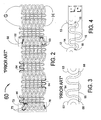
- FIG. 1 shows a flat layout of an embodiment of a prior art stent described by Fischell et al in US Patent Application S/N 09/192,101 .
- the stent 5 of FIG. 1 is shown in its crimped, pre-deployed state as it would appear if it were cut longitudinally and then laid out into a flat, 2-dimensional configuration.
- the stent 5 comprises end sets of strut members 2 located at each end of the stent 5 and three central sets of strut members 6 connected each to the other by sets of longitudinally extending undulating "N" links 4.
- the end sets of strut members 2 consist of alternating curved sections 7 and diagonal sections 9.
- the central sets of strut members 6 located longitudinally between the end sets of strut members 2 consist of alternating curved sections 3 and diagonal sections 8.
- the longitudinally diagonal sections 9 of the end sets of strut members 2 are shorter in length than the longitudinally diagonal sections 8 of the central sets of strut members 6.
- the shorter diagonal sections 9 will reduce the stiff longitudinal length of metal at the ends of the stent 5 to improve deliverability (by reducing "fish-scaling") and will also increase the postexpansion strength of the end sets of strut members 2 as compared with the central sets of strut members 6.
- the width of the curved sections 3 and 7 and the diagonal sections 8 and 9 are all the same.
- the stent 5 is a design well suited to stainless steel having a wall thickness of 0.11mm (0.0045") or greater, such as found in the CORDIS BX Velocity@ stent.
- the stent 5 were formed from a highly radio-opaque metal such as tantalum with wall thickness of 0.076 to 0.089mm (0.0030 to 0.0035 inches) and with sets of strut members 6 having widths of greater than the 0.13mm (0.005 inches) that is necessary for good radial strength, then the stent would be too radio-opaque.
- the end sets of strut members 2 might have a tendency to flare outwardly into the vessel wall upon expansion.
- the central sets of strut members 6 with longer diagonal sections 8 will not have maximized radial strength assuming the same strut width for both central sets of strut members 6 and end sets of strut members 2.
- Optimized strength at the longitudinal center of a stent is important as it is that region that must typically hold back a larger amount of plaque than at the ends of the stent.
- each set of strut members should have maximized radial strength rather than having the central sets of strut members 6 being less strong than the end sets of strut members as previously described.
- This design would be similar to the stent 5 of FIG. 1 with the novel improvement being that the width of the curved sections 3 of the central sets of strut members 6 would be greater than the width of the curved sections 7 of the end sets of strut members 2. The greater width of the curved sections 3 will increase the strength of the central sets of strut members 6 compensating for loss of radial strength because of the longer diagonal sections 8.
- the stent 60 shown in FIG. 2 is a flat layout of a prior art stent design having "N", “M” and “W” flexible connecting links.
- the stent 60 is shown in its crimped pre-deployed state as it would appear if it were cut longitudinally and then laid out into a flat, 2-dimensional configuration. It should be clearly understood that the stent 60 is in fact cylindrical in shape, which cylindrical shape would be obtained by rolling the flat configuration of FIG. 2 into a cylinder with the top points "G" joined to the bottom points "H”.
- the stent 60 is typically fabricated by laser machining of a cylindrical, stainless steel tube.
- a central set of strut members 62 is a cylindrical, closed, ring-like section of the stent 60 consisting of a multiplicity of curved sections 63 connected to diagonal sections 68. Every curved section 63 of each central set of strut members 62 is attached to a connecting link which is either a flexible "N" link 44, "M” link 64 or a "W” link 84.
- the stent 60 also has two end sets of strut members 72 consisting of a multiplicity of curved sections 73 connected to diagonal sections 78. In this embodiment, half of the curved sections 73 of the end set of strut members 72 are attached to "N" links 44 with the other half of the curved sections 73 situated at the extreme ends of the stent 60.
- the diagonal sections 78 of the end sets of strut members 72 are shorter than the diagonal sections 68 of the central sets of strut members 62. Shorter diagonal sections enhance the post-expansion radial strength of the end sets of strut members 72 as compared to the central sets of strut members 62.
- FIG. 3 is an enlargement of the "M" link 64 of the prior art stent of FIG. 2 .
- One disadvantage of this design relates to the circumferential extent of the "M” link 64 with respect to a line 65 that could be drawn between the two attachment points 68 where the "M” link 64 attaches to the curved sections 63. Because almost all of the "M” link 64 lies above the line 65, pressure on the top of the "M” link 64 from plaque in an artery could bend the top of the "M” link 64 inward into the arterial lumen. This would be highly undesirable.
- an "M" or “W” link should have an equal circumferential extent on either side of a line drawn between the attachment points to adjacent sets of strut members as shown in FIG. 4 .
- the "M” link 14 has a circumferential extent (i.e., length) L' above and L" below the line 15.
- the line 15 is drawn between the attachment points 18 where the "M" link 14 attaches to adjacent curved sections 13.
- Such a balanced design would diminish any likelihood of the flexible connecting link 14 from expanding into the arterial lumen.
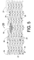
- FIG. 5 is a flat layout view of a stent 20 that includes some embodiments of the present invention.
- the design of FIG. 5 is particularly applicable to stents made from a highly radio-opaque metal such as tantalum.
- the stent 20 of FIG. 5 is shown in flat, layout view based on its pre-deployed state, as it would appear before it is crimped onto a balloon catheter.
- the stent 20 comprises end sets of strut members 22 located at each end of the stent 20 and central sets of strut members 26 connected each to the other by sets of individual flexible "M" links 24.
- the "M" links 24 are similar to the "M” linkl4 of FIG. 4 .
- the end sets of strut members 22 consist of a multiplicity of curved sections 27 connected to diagonal sections 29.
- the central sets of strut members 26 located longitudinally between the end sets of strut members 22 consist of a multiplicity of curved sections 23 connected to diagonal sections 28.
- a strut element 25 as being composed of one adjacent curved section 23 joined to a diagonal section 28.
- a central set of strut members 26 as being a closed, circumferential, ring-like structure comprising a multiplicity of connected strut elements 25.
- An end set of strut members could be likewise defined as being a multiplicity of connected strut elements 17.
- the stent 20 is a closed cell stent having cells 19 formed from portions of adjacent sets of strut members connected by "M" links 24.
- M strut members connected by "M" links 24.
- prolapse of plaque into the arterial lumen will be minimized if the area within the cell 19 does not exceed 0.032cm 2 (0.005 square inches) at all diameters up to the maximum deployment diameter of the stent 20.
- An important aspect of stent design is to be able to place a guidewire through the expanded cell 19, into a side branch vessel. A balloon angioplasty catheter can then be advanced over the guidewire and inflated to enlarge and circularize the opening of the cell 19 to "unjail" the side branch vessel.
- the cell 19 has an interior length of the perimeter that is at least 9 mm. Since balloon dilatation of the cell 19 would cause it to be near circular, a perimeter length of the cell 19 would provide a diameter of 9/ ⁇ , which is approximately 3 mm.
- a good cell design for side branch access should have a perimeter between 9 mm and 11 mm. (i. e., an expanded circular diameter between 2.86 and 3.5 mm) where cell perimeters between 9. 5 and 10 mm are optimal and would be suitable for essentially any side branch of a coronary artery.
- the diagonal sections 29 of the end sets of strut members 22 are shorter in length than the diagonal sections 28 of the central sets of strut members 26.
- the shorter diagonal sections 29 will reduce the longitudinal extent of the metal strut at the end of the stent to improve deliverability into a vessel of the human body by decreasing fish-scaling.
- the width of the curved sections 23 and 27 and the diagonal sections 28 and 29 are different as compared to the prior art stents 5 and 6 of FIGURES 1 and 2 .
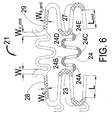
- FIG. 6 shows that the curved sections 23 (of the central sets of strut members 26 of FIG. 5 ) have a width at the center of the curve W c .
- the width of the curved sections 23 taper down as one moves away from the center of the curve until a minimum width W d is reached at the center of the section 28.
- the inside arc of the curved section 23 has a center that is longitudinally displaced from the center of the outside arc. This tapered shape for the curved section 23 provides a significant reduction in metal strain with little effect on the radial strength of the expanded stent as compared to a stent having sets of strut members with a uniform strut width.
- This reduced strain design has several advantages. First, it can allow the present invention design to have a much greater usable range of radial expansion as compared to a stent with a uniform strut width. Second, it can allow the width at the center of the curve to be increased which increases radial strength without greatly increasing the metal strain (i.e. one can make a stronger stent). Finally, the taper reduces the amount of metal in the stent and that should improve the stent thrombogenicity.
- FIG. 6 also shows a unique design for the end sets of strut members 22.
- the diagonal sections of the end sets of strut members 22 have a length L end that is shorter than the length L of the diagonal sections 28 of the central sets of strut members 26.
- each set of strut members should just reach the maximum allowable plastic strain for the metal being used at the largest allowable expanded diameter of the stent.
- the curved sections 7 of the end sets of strut members 2 and the curved sections 3 of the central sets of strut members 6 have the same widths.
- the end sets of strut members 2 (which have shorter diagonal sections 9) will reach the maximum allowable diameter at a level of strain that is greater than the level of strain experienced by the central sets of strut members 6.
- An optimum strength stent design would have the same strain at the maximum stent diameter for both the end sets of strut members 2 and the central sets of strut members 6.
- the end sets of strut members 22 reach the maximum strain limit at the same stent diameter as the central sets of strut members 26.
- the present invention teaches a design with the width at the center of the curve W c_end of the curved section 27 being less than the width W c of the curved sections 23 of the central sets of strut members 26. This reduced width for the curved sections 23 compensates for the shorter length L end of the end diagonal sections 29 so that there is the same strain in both the central and end sets of strut members 22 and 26 respectively as the stent 20 is expanded to its maximum allowable diameter.
- the end sets of strut members 22 can also be tapered like the central sets of strut members 26 where the width of the strut tapers down as one moves away from the center of the curve of the curved sections 27 until a minimum width W d_end is reached at the diagonal section 29.
- the curved sections 23,27 each have an inside (concave) arc and an outside (convex) arc. Each arc has a center that is longitudinally displaced from the other center.
- the tapered strut design shown in FIGS. 5 and 6 also has an advantage for stents made from highly radio-opaque metals such as tantalum. If one uses uniform strut width as seen with the stent 5 of FIG. 1 , then a properly designed thin-walled 0.064mm (0.0025 inches) to 0.89mm (0.035 inches) wall tantalum stent may be too radio-opaque. The reduced metal from the thinner diagonal sections 28 and 29 will decrease the radio-opacity without affecting radial strength. Nominal dimensions and dimension ranges (all in mm (inches)) for a tantalum stent produced... using the design of FIG.
- the present invention shows the "M” shaped flexible link 24 being used, the present invention strut designs will function with any link shape including “N”, “W”, “S” “U”, “V” and inverted “N”, “U” and “V” designs. It should also be noted that the "M” link 24 shown in FIG. 6 has exactly five longitudinally extending curved segments 24A, 24B, 24C, 24D and 24E.
- FIG. 7 is an alternative embodiment 21' of section 21 shown in FIG. 6 of the present invention stent 20 of FIG. 5 .
- the diagonal sections 28 of FIG. 6 have uniform thickness.
- the diagonal sections 28' of FIG. 7 are tapered from a width W d " at the end of the diagonal section 28' where it connects to the curved sections 23' to a width W d ' at the center of the diagonal section 28'.
- the advantage of the inward taper of the diagonal sections 28' is that removal of more metal will reduce the radio-opacity of the longitudinal center region of the stent 20 as compared to a stent with uniform width diagonal sections 28 as seen in FIG. 6 .
- the additional taper may also further reduce the metal strain as the stent is expanded.
- one could taper the diagonal sections 29 of the end sets of strut members 22 of FIG. 5 there is an advantage in having the end sets of strut members 22 being more radio-opaque than the central sets of strut members 26. This is because visualization of the stent ends is the most important aspect of radio-opacity for a stent. Therefore, a preferred embodiment of the present invention is as seen in FIG. 7 to have tapered diagonal sections 28' in the central sets of strut members 26 and uniform thickness diagonal sections 29 (having a greater average width) for the end sets of strut members 22.
- an alternate embodiment may use straight links connecting only half of the curved sections of the sets of strut members. Such a design, would also have the advantages of the reduce strain strut designs as shown in FIGS. 5 , 6 and 7 .
- the wall thickness of the central set of strut members 26 could be thinner that the wall thickness of the end set of strut members 22.
- the "M" links 24 also have a much narrower width as compared to the width of any strut member of the end set of strut members. Both these attributes of the stent 20 create the following desirable radio-opacity characteristics: highly radio-opaque end sets of strut members and decreased radio-opacity at the central region of the stent 20.
- FIG. 8 is a flat layout view of another embodiment of the present invention showing a stent 30 made from a moderately radio-opaque metal such as the cobalt-tungsten alloy L605.
- the alloy L605 has great radial strength and is approximately 20% to 30% more radio-opaque than stainless steel. Therefore, with L605, the same level of radio-opacity is achieved with a stent wall thickness that is 20% to 30% less than a stent made from stainless steel.
- One goal in the use of L605 would be to reduce the wall thickness by 30% but end up with a stent that is still more radio-opaque than an equivalent stainless steel stent such as the stent 5 shown in FIG. 1 .
- the stent 30 of FIG. 8 is shown in a layout view based on its pre-deployed state, as it would appear before it is crimped onto a balloon catheter.
- the stent 30 comprises end sets of strut members 32 located at each end of the stent 30 and central sets of strut members 36 connected each to the other by sets of flexible "M" links 34.
- the "M" links 34 are similar to the "M” links 14 of FIG. 4 .
- Each end set of strut members 32 comprises alternating curved sections 37 and diagonal sections 39 connected together to form a closed circumferential structure.
- the central sets of strut members 36 located longitudinally between the end sets of strut members 32 comprises curved sections 33 and diagonal sections 38 connected together to form a closed circumferential ring-like structure.
- the diagonal sections 39 of the end sets of strut members 32 are shorter in length than the diagonal sections 38 of the central sets of strut members 36.
- the shorter diagonal sections 39 will reduce the longitudinal length of metal at the end of the stent to improve deliverability into a vessel of the human body.
- the widths of the diagonal sections 38 and 39 are different as compared to the prior art stents 5 and 60 of FIGS. 1 and 2 .
- FIG. 9 it can be seen that the diagonal sections 38 of the central sets of strut members 36 have a width at the center T c and a width at the end T e where the width in the center T c is larger than the width at the end T e .
- the curved sections 33 and 37 shown in FIG. 9 are tapered similar to the curved sections 23 and 27 of FIG. 6 . It is also envisioned that the curved sections 33 and 37 could have uniform width similar to the curved sections 3 and 7 of FIG.
- the diagonal sections 39 of the end sets of strut members 32 also have a tapered shape.
- the diagonal sections 37 have a width in the center T c_end and a width at the end T e_end where the width in the center T c_end is larger than the width at the end T e _ end .
- the diagonal section 39 center width T c_end of the end sets of strut members 32 is shown in FIG. 9 to be wider than the width T c of the diagonal section 38. A wider piece of metal will be more radio-opaque.
- the stent has curved sections with a single bend connecting the diagonal sections of its sets of strut members, and flexible connecting links connecting the curved sections of its circumferential sets of strut members.
- the stent of FIG. 10 is an alternate embodiment of the present invention showing central sets of strut members 46 having curved sections 43 and diagonal sections 48 with tapered shapes similar in design to the curved sections 23' and diagonal sections 28' of the stent section 21' shown in FIG. 7 .
- the stent 40 of FIG. 10 is shown in a layout view in its pre-deployed state as it would appear before it is crimped onto a balloon catheter.
- the stent 40 comprises end sets of strut members 42 located at each end of the stent 40 and central sets of strut members 46.
- the sets of strut members 42 and 46 are connected each to the other by sets of individual flexible "N" links 44.
- the "N" links 44 are similar in shape but slightly longer than the "N" links 4 of FIG. 1 .
- the end sets of strut members 42 consist of curved sections 47 and diagonal sections 49.
- the central sets of strut members 46 located longitudinally between the end sets of strut members 42 consist of curved sections
- the stent 40 is a closed cell stent having cells 45 formed from portions of adjacent sets of strut members connected by "N" links 44. Prolapse of plaque through the closed cells 45 is minimized if the expanded area of the cell 45 is less than about 0.032cm 2 (0. 005 in. 2 ) at any diameter up to the maximum deployment diameter of the stent 40. It is also important for an optimum stent design that a guidewire can be placed through the expanded cell 45 into a side branch vessel. A balloon angioplasty catheter would then be advanced over the guidewire, through the cell 45 and inflated to "unjail" the side branch, i.e. remove any stent strut that is blocking blood flow into that side branch.
- the present invention design should have an interior perimeter of the cell 45 that is at least 9 mm, thus allowing a nearly 3 mm diameter circular opening to be achieved for unjailing.
Landscapes
- Health & Medical Sciences (AREA)
- Engineering & Computer Science (AREA)
- Biomedical Technology (AREA)
- Life Sciences & Earth Sciences (AREA)
- Veterinary Medicine (AREA)
- Public Health (AREA)
- General Health & Medical Sciences (AREA)
- Animal Behavior & Ethology (AREA)
- Heart & Thoracic Surgery (AREA)
- Cardiology (AREA)
- Vascular Medicine (AREA)
- Transplantation (AREA)
- Oral & Maxillofacial Surgery (AREA)
- Physics & Mathematics (AREA)
- Optics & Photonics (AREA)
- Anesthesiology (AREA)
- Hematology (AREA)
- Media Introduction/Drainage Providing Device (AREA)
- Prostheses (AREA)
- Materials For Medical Uses (AREA)
Abstract
Description
- This invention is in the field of stents for implantation into a vessel of a human body.
- Stents are well known medical devices that are used for maintaining the patency of a large variety of vessels of the human body. A more frequent use is for implantation into the coronary vasculature. Although stents have been used for this purpose for more than ten years, and some current stent designs such as the CORDIS BX Velocity ® stent, Cordis Corporation, Miami Lakes, FL, have the required flexibility and radial rigidity to provide an excellent clinical result, they are not always clearly seen under standard fluoroscopy.
- Many current tubular stents use a multiplicity of circumferential sets of strut members connected by either straight longitudinal connecting links or undulating longitudinal connecting links. The circumferential sets of strut members are typically formed from a series of diagonal sections connected to curved sections forming a closed-ring, zig-zag structure. This structure opens up as the stent expands to form the element in the stent that provides structural support for the arterial wall. A single strut member can be thought of as a diagonal section connected to a curved section within one of the circumferential sets of strut members. In current stent designs such as the BX Velocity ® stent, these sets of strut members are formed from a single piece of metal having a uniform wall thickness and generally uniform strut width. Although a stent with uniform width of the strut members will function, if the width is increased to add strength or radio-opacity, the sets of strut members will experience increased strain upon expansion. High strain can cause cracking of the metal and potential fatigue failure of the stent under the cyclic stress of a beating heart.
- Existing highly radio-opaque stents, such as the gold plated NIROYA™ stent sold by Boston Scientific, Inc., Natick MA, can obscure the inside of the vessel due to the high radio-opacity over the entire length of the stent. The BeStent™ sold by Medtronic, Inc., Minneapolis MN, has small gold markers at the ends of the stent. Those markers only mark an end point without allowing visualization of the entire end set of strut members.
-
Fischell et al, in US Patent No. 6,086,604 , discloses a stent with the end sets of strut members being gold plated. Such a stent would have ideal radio-opacity but may be subject to the corrosive effects incurred through placement of dissimilar in an electrolytic solution such as blood. There has also been significant evidence that gold is a poor surface material for stents because it may increase the risk of subacute thrombosis or restenosis. Further,Fischell et al, US Patent No. 5,697,971 discloses in itsFIG. 7 , a stainless steel stent with increased width diagonal sections in all the circumferential sets of strut members. -
WO-A-98/40035 - Described herein are the novel design elements for stents that may be formed from the following materials:
- 1. A highly radio-opaque metal such as tantalum;
- 2. Metals somewhat more radio-opaque than stainless steel, such as the cobalt based alloy L605;
- 3. Stents coated or plated with highly radio-opaque materials like gold; and
- 4. Layered materials such as alternative layers of tantalum and stainless steel.
- According to the present invention there is provided a deployed stent as defined in appended
claim 1. - The stent of the invention allows good side branch arterial access while maintaining small cell size. The stents described herein are typically closed cell stents, having a curved section of a central set of strut members connected to an adjacent set of strut members by a longitudinally extending link. In one embodiment of the present invention, the circumferential sets of strut members are joined by undulating longitudinal connecting links with each link having a multiplicity of curved segments so as to increase the perimeter of the stent's closed cells. One aspect of the present invention is that the perimeter of at least half of the stent's closed cells, more preferably each of the stent's closed cells should be at least 9 mm long. This design parameter allows each cell of the stent to be expanded to a circular diameter of approximately 3 mm (i.e., 9/π mm-3 mm). This feature allows the "unjailing" of side branches of the artery into which the stent is placed. The ideal design to be radially strong, prevent plaque prolapse and still allow sidebranch access will have a maximum deployed cell area of less than 0.032cm2 (0.005 in2) while having a cell perimeter that is at least 9 mm in length, so as to allow unjailing of side branches. A good cell for side branch access should have a perimeter length between 9 mm and 11 mm (i.e. an expandable circular diameter between 2.86 mm and 3.5 mm). Cell perimeters between 9.5 and 10 mm are optimal.
- The present invention also makes use of flexible undulating longitudinal links with good support between adjacent sets of strut members. To provide a strong bridge connection between adjacent circumferential sets of strut members, the flexible undulating longitudinal connecting links should have nearly equal extension in the circumferential direction on each side of a line drawn between the attachment points of the flexible undulating longitudinal connecting link to the curved sections of adjacent sets of strut members. "N" and inverted "N" shapes for the connecting links inherently have equal circumferential displacement on each side of the line connecting their attachment points. The specially designed "M" or "W" shapes of the present invention also provide this desirable attribute. Nearly equal circumferential lengths on either side of a line drawn between the attachment points of the flexible undulating longitudinal connecting links help in preventing plaque from pushing the "M" or "W" shaped link inward when. the stent is deployed into an artery.
- The "M" and "W" shapes are of particular advantage in obtaining the desired attribute of small area cells that have good side branch access capability because of an increased perimeter length. It should also be understood that the "M" and "W" shapes each add an additional half cycle of undulating link length to the cell perimeter as compared to an "N" shaped link design, thus improving the stent's longitudinal flexibility. It should also be noted that a "W" link is simply an inverted "M" link.
- The present invention may provide a closed cell stent design with maximum post-deployment cell area less than 0.032cm2 (0.005 square inches) and a cell perimeter length that is equal to or greater than 9mm.
- The present invention may provide a closed cell stent design with "M" or "W" shaped flexible undulating longitudinal connecting links wherein the circumferential extent of the flexible undulating longitudinal connecting links is approximately equal on each side of a line drawn between the proximal and distal attachment points of the flexible undulating longitudinal connecting link.
- These and other advantages of this invention will become apparent to the person of ordinary skill in this art field upon reading of the detailed description of this invention including the associated drawings.
-
-
FIG. 1 is a flat layout of a prior art stent having uniform strut width for the circumferential sets of strut members. -
FIG. 2 is a flat layout of a prior art stent design having "M" and "W" flexible connecting links. -
FIG. 3 is an enlargement of the "M" link of the stent design ofFIG. 2 . -
FIG. 4 is an enlargement of the improved "M" link design of the present invention. -
FIG. 5 is a flat layout of the present invention stent design for a highly radio-opaque metal. -
FIG. 6 is a flat layout of part of the present invention stent design ofFIG. 5 . -
FIG. 7 is a flat layout of an alternate embodiment of part of the present invention stent design ofFIG. 5 . -
FIG. 8 is a flat layout of the present invention stent design for a somewhat radio-opaque metal. -
FIG. 9 is a flat layout of the present invention stent design for a stent coated with a radio-opaque metal. -
FIG. 10 is a flat layout of an alternate embodiment of the present invention stent including an "N" shaped flexible connecting link. -
FIG. 11 is a flat layout of the present invention stent design as photo-etched from a tube. -
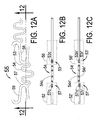
FIG. 12A is an enlargement of a section of the photo-etched stent ofFIG. 11 . -
FIG. 12B is a longitudinal cross section at 12-12 of the enlarged section ofFIG. 11 shown inFIG. 12A , the stent having a radio-opaque coating that is thickest on the end sets of strut members. -
FIG. 12C is a longitudinal cross section at 12-12 of the enlarged section ofFIG. 11 shown inFIG. 12A , as etched from a two-layer tube where one of the tube layers is a moderately radio-opaque metal and the other layer is a highly radio-opaque metal. -
FIG. 1 shows a flat layout of an embodiment of a prior art stent described byFischell et al in US Patent Application S/N 09/192,101 . Thestent 5 ofFIG. 1 is shown in its crimped, pre-deployed state as it would appear if it were cut longitudinally and then laid out into a flat, 2-dimensional configuration. Thestent 5 comprises end sets ofstrut members 2 located at each end of thestent 5 and three central sets of strut members 6 connected each to the other by sets of longitudinally extending undulating "N" links 4. The end sets ofstrut members 2 consist of alternating curved sections 7 anddiagonal sections 9. The central sets of strut members 6 located longitudinally between the end sets ofstrut members 2 consist of alternatingcurved sections 3 and diagonal sections 8. In theprior art stent 5, the longitudinallydiagonal sections 9 of the end sets ofstrut members 2 are shorter in length than the longitudinally diagonal sections 8 of the central sets of strut members 6. The shorterdiagonal sections 9 will reduce the stiff longitudinal length of metal at the ends of thestent 5 to improve deliverability (by reducing "fish-scaling") and will also increase the postexpansion strength of the end sets ofstrut members 2 as compared with the central sets of strut members 6. In this prior art stent, the width of thecurved sections 3 and 7 and thediagonal sections 8 and 9 are all the same. There is no variation in width within any set of strut members or between the end sets ofstrut members 2 and the central sets of strut members 6. Thestent 5 is a design well suited to stainless steel having a wall thickness of 0.11mm (0.0045") or greater, such as found in the CORDIS BX Velocity@ stent. - If the
stent 5 were formed from a highly radio-opaque metal such as tantalum with wall thickness of 0.076 to 0.089mm (0.0030 to 0.0035 inches) and with sets of strut members 6 having widths of greater than the 0.13mm (0.005 inches) that is necessary for good radial strength, then the stent would be too radio-opaque. In addition, with a wall thickness of 0.076mm (0.003 inches) or less, the end sets ofstrut members 2 might have a tendency to flare outwardly into the vessel wall upon expansion. - If the end sets of
strut members 2 are designed to be as strong as possible while not exceeding metal strain limits at the largest usable diameter of thestent 5, then the central sets of strut members 6 with longer diagonal sections 8 will not have maximized radial strength assuming the same strut width for both central sets of strut members 6 and end sets ofstrut members 2. Optimized strength at the longitudinal center of a stent is important as it is that region that must typically hold back a larger amount of plaque than at the ends of the stent. - One embodiment of the present invention provides that each set of strut members should have maximized radial strength rather than having the central sets of strut members 6 being less strong than the end sets of strut members as previously described. This design would be similar to the
stent 5 ofFIG. 1 with the novel improvement being that the width of thecurved sections 3 of the central sets of strut members 6 would be greater than the width of the curved sections 7 of the end sets ofstrut members 2. The greater width of thecurved sections 3 will increase the strength of the central sets of strut members 6 compensating for loss of radial strength because of the longer diagonal sections 8. - The
stent 60 shown inFIG. 2 is a flat layout of a prior art stent design having "N", "M" and "W" flexible connecting links. Thestent 60 is shown in its crimped pre-deployed state as it would appear if it were cut longitudinally and then laid out into a flat, 2-dimensional configuration. It should be clearly understood that thestent 60 is in fact cylindrical in shape, which cylindrical shape would be obtained by rolling the flat configuration ofFIG. 2 into a cylinder with the top points "G" joined to the bottom points "H". Thestent 60 is typically fabricated by laser machining of a cylindrical, stainless steel tube. - A central set of
strut members 62 is a cylindrical, closed, ring-like section of thestent 60 consisting of a multiplicity ofcurved sections 63 connected todiagonal sections 68. Everycurved section 63 of each central set ofstrut members 62 is attached to a connecting link which is either a flexible "N"link 44, "M"link 64 or a "W"link 84. Thestent 60 also has two end sets ofstrut members 72 consisting of a multiplicity ofcurved sections 73 connected todiagonal sections 78. In this embodiment, half of thecurved sections 73 of the end set ofstrut members 72 are attached to "N" links 44 with the other half of thecurved sections 73 situated at the extreme ends of thestent 60. Thediagonal sections 78 of the end sets ofstrut members 72 are shorter than thediagonal sections 68 of the central sets ofstrut members 62. Shorter diagonal sections enhance the post-expansion radial strength of the end sets ofstrut members 72 as compared to the central sets ofstrut members 62. -
FIG. 3 is an enlargement of the "M"link 64 of the prior art stent ofFIG. 2 . One disadvantage of this design relates to the circumferential extent of the "M"link 64 with respect to aline 65 that could be drawn between the two attachment points 68 where the "M"link 64 attaches to thecurved sections 63. Because almost all of the "M"link 64 lies above theline 65, pressure on the top of the "M"link 64 from plaque in an artery could bend the top of the "M"link 64 inward into the arterial lumen. This would be highly undesirable. Ideally, an "M" or "W" link should have an equal circumferential extent on either side of a line drawn between the attachment points to adjacent sets of strut members as shown inFIG. 4 . - One aspect of the present invention is an improved "M"
link 14 as shown inFIG. 4 . The "M"link 14 has a circumferential extent (i.e., length) L' above and L" below theline 15. Theline 15 is drawn between the attachment points 18 where the "M"link 14 attaches to adjacentcurved sections 13. Such a balanced design would diminish any likelihood of the flexible connectinglink 14 from expanding into the arterial lumen. -
FIG. 5 is a flat layout view of astent 20 that includes some embodiments of the present invention. The design ofFIG. 5 is particularly applicable to stents made from a highly radio-opaque metal such as tantalum. Thestent 20 ofFIG. 5 is shown in flat, layout view based on its pre-deployed state, as it would appear before it is crimped onto a balloon catheter. Thestent 20 comprises end sets ofstrut members 22 located at each end of thestent 20 and central sets ofstrut members 26 connected each to the other by sets of individual flexible "M" links 24. The "M" links 24 are similar to the "M" linkl4 ofFIG. 4 . The end sets ofstrut members 22 consist of a multiplicity ofcurved sections 27 connected todiagonal sections 29. The central sets ofstrut members 26 located longitudinally between the end sets ofstrut members 22 consist of a multiplicity ofcurved sections 23 connected todiagonal sections 28. - One can also define a
strut element 25 as being composed of one adjacentcurved section 23 joined to adiagonal section 28. As seen inFIG. 5 , it is clear that one can describe a central set ofstrut members 26 as being a closed, circumferential, ring-like structure comprising a multiplicity ofconnected strut elements 25. An end set of strut members could be likewise defined as being a multiplicity ofconnected strut elements 17. - The
stent 20 is a closed cellstent having cells 19 formed from portions of adjacent sets of strut members connected by "M" links 24. For coronary arteries, prolapse of plaque into the arterial lumen will be minimized if the area within thecell 19 does not exceed 0.032cm2 (0.005 square inches) at all diameters up to the maximum deployment diameter of thestent 20. An important aspect of stent design is to be able to place a guidewire through the expandedcell 19, into a side branch vessel. A balloon angioplasty catheter can then be advanced over the guidewire and inflated to enlarge and circularize the opening of thecell 19 to "unjail" the side branch vessel. By "unjailing" is meant removing metal from the ostium of the side branch vessel, thus improving blood flow to that side branch. One concept of the present invention is that thecell 19 has an interior length of the perimeter that is at least 9 mm. Since balloon dilatation of thecell 19 would cause it to be near circular, a perimeter length of thecell 19 would provide a diameter of 9/π, which is approximately 3 mm. A good cell design for side branch access should have a perimeter between 9 mm and 11 mm. (i. e., an expanded circular diameter between 2.86 and 3.5 mm) where cell perimeters between 9. 5 and 10 mm are optimal and would be suitable for essentially any side branch of a coronary artery. - In the
stent 20, thediagonal sections 29 of the end sets ofstrut members 22 are shorter in length than thediagonal sections 28 of the central sets ofstrut members 26. The shorterdiagonal sections 29 will reduce the longitudinal extent of the metal strut at the end of the stent to improve deliverability into a vessel of the human body by decreasing fish-scaling. In thestent 20, the width of thecurved sections diagonal sections prior art stents 5 and 6 ofFIGURES 1 and2 . - The exact design of the
stent 20 is most clearly seen in the expanded view of thestent section 21 ofFIG. 5 as shown enlarged inFIG. 6. FIG. 6 shows that the curved sections 23 (of the central sets ofstrut members 26 ofFIG. 5 ) have a width at the center of the curve Wc. The width of thecurved sections 23 taper down as one moves away from the center of the curve until a minimum width Wd is reached at the center of thesection 28. To achieve this taper, the inside arc of thecurved section 23 has a center that is longitudinally displaced from the center of the outside arc. This tapered shape for thecurved section 23 provides a significant reduction in metal strain with little effect on the radial strength of the expanded stent as compared to a stent having sets of strut members with a uniform strut width. - This reduced strain design has several advantages. First, it can allow the present invention design to have a much greater usable range of radial expansion as compared to a stent with a uniform strut width. Second, it can allow the width at the center of the curve to be increased which increases radial strength without greatly increasing the metal strain (i.e. one can make a stronger stent). Finally, the taper reduces the amount of metal in the stent and that should improve the stent thrombogenicity.
-
FIG. 6 also shows a unique design for the end sets ofstrut members 22. The diagonal sections of the end sets ofstrut members 22 have a length Lend that is shorter than the length L of thediagonal sections 28 of the central sets ofstrut members 26. To maximize the radial strength of a stent along its entire length, each set of strut members should just reach the maximum allowable plastic strain for the metal being used at the largest allowable expanded diameter of the stent. In the stent ofFIG. 1 , the curved sections 7 of the end sets ofstrut members 2 and thecurved sections 3 of the central sets of strut members 6 have the same widths. As a result, the end sets of strut members 2 (which have shorter diagonal sections 9) will reach the maximum allowable diameter at a level of strain that is greater than the level of strain experienced by the central sets of strut members 6. - An optimum strength stent design would have the same strain at the maximum stent diameter for both the end sets of
strut members 2 and the central sets of strut members 6. For the stent design ofFIGS. 5 and6 , one desires to have the end sets ofstrut members 22 reach the maximum strain limit at the same stent diameter as the central sets ofstrut members 26. The present invention teaches a design with the width at the center of the curve Wc_end of thecurved section 27 being less than the width Wc of thecurved sections 23 of the central sets ofstrut members 26. This reduced width for thecurved sections 23 compensates for the shorter length Lend of the enddiagonal sections 29 so that there is the same strain in both the central and end sets ofstrut members stent 20 is expanded to its maximum allowable diameter. - The end sets of
strut members 22 can also be tapered like the central sets ofstrut members 26 where the width of the strut tapers down as one moves away from the center of the curve of thecurved sections 27 until a minimum width Wd_end is reached at thediagonal section 29. Thecurved sections - The tapered strut design shown in
FIGS. 5 and6 also has an advantage for stents made from highly radio-opaque metals such as tantalum. If one uses uniform strut width as seen with thestent 5 ofFIG. 1 , then a properly designed thin-walled 0.064mm (0.0025 inches) to 0.89mm (0.035 inches) wall tantalum stent may be too radio-opaque. The reduced metal from the thinnerdiagonal sections FIG. 5 are as follows:Element Nominal Range Wc 0.15 (0.006) 0.11 to 0.18 (0.0045 to 0.007) Wd 0.11 (0.0045) 0.89 to 0.13 (0.035 to 0.005) Wc_end 0.11 (0.0045) 0.10 to 0.13 (0.004 to 0.005) Wd_end 0.11 (0.0045) 0.89 to 0.13 (0.035 to 0.005) L 0.71 (0.028) 0.51 to 0.76 (0.020 to 0.030) Lend 0.64 (0.025) 0.38 to 0.66 (0.015 to 0.026) Wall Thickness 0.076 (0.003) 0.064 to 0.89 (0.0025 to 0.035) - Although the present invention shows the "M" shaped
flexible link 24 being used, the present invention strut designs will function with any link shape including "N", "W", "S" "U", "V" and inverted "N", "U" and "V" designs. It should also be noted that the "M"link 24 shown inFIG. 6 has exactly five longitudinally extendingcurved segments -
FIG. 7 is an alternative embodiment 21' ofsection 21 shown inFIG. 6 of thepresent invention stent 20 ofFIG. 5 . In this embodiment, the only difference is the shape of the diagonal sections 28'. Thediagonal sections 28 ofFIG. 6 have uniform thickness. The diagonal sections 28' ofFIG. 7 are tapered from a width Wd" at the end of the diagonal section 28' where it connects to the curved sections 23' to a width Wd' at the center of the diagonal section 28'. The advantage of the inward taper of the diagonal sections 28' is that removal of more metal will reduce the radio-opacity of the longitudinal center region of thestent 20 as compared to a stent with uniform widthdiagonal sections 28 as seen inFIG. 6 . The additional taper may also further reduce the metal strain as the stent is expanded. Although one could taper thediagonal sections 29 of the end sets ofstrut members 22 ofFIG. 5 , there is an advantage in having the end sets ofstrut members 22 being more radio-opaque than the central sets ofstrut members 26. This is because visualization of the stent ends is the most important aspect of radio-opacity for a stent. Therefore, a preferred embodiment of the present invention is as seen inFIG. 7 to have tapered diagonal sections 28' in the central sets ofstrut members 26 and uniform thickness diagonal sections 29 (having a greater average width) for the end sets ofstrut members 22. - Instead of connecting every curved section with a flexible link, an alternate embodiment may use straight links connecting only half of the curved sections of the sets of strut members. Such a design, would also have the advantages of the reduce strain strut designs as shown in
FIGS. 5 ,6 and7 . - For the stent of
FIG. 5 , it should also be understood that the wall thickness of the central set ofstrut members 26 could be thinner that the wall thickness of the end set ofstrut members 22. Also it should be noted that the "M" links 24 also have a much narrower width as compared to the width of any strut member of the end set of strut members. Both these attributes of thestent 20 create the following desirable radio-opacity characteristics: highly radio-opaque end sets of strut members and decreased radio-opacity at the central region of thestent 20. -
FIG. 8 is a flat layout view of another embodiment of the present invention showing astent 30 made from a moderately radio-opaque metal such as the cobalt-tungsten alloy L605. The alloy L605 has great radial strength and is approximately 20% to 30% more radio-opaque than stainless steel.
Therefore, with L605, the same level of radio-opacity is achieved with a stent wall thickness that is 20% to 30% less than a stent made from stainless steel.
One goal in the use of L605 would be to reduce the wall thickness by 30% but end up with a stent that is still more radio-opaque than an equivalent stainless steel stent such as thestent 5 shown inFIG. 1 . - The
stent 30 ofFIG. 8 is shown in a layout view based on its pre-deployed state, as it would appear before it is crimped onto a balloon catheter.
Thestent 30 comprises end sets ofstrut members 32 located at each end of thestent 30 and central sets ofstrut members 36 connected each to the other by sets of flexible "M" links 34. The "M" links 34 are similar to the "M" links 14 ofFIG. 4 . Each end set ofstrut members 32 comprises alternatingcurved sections 37 anddiagonal sections 39 connected together to form a closed circumferential structure. The central sets ofstrut members 36 located longitudinally between the end sets ofstrut members 32 comprisescurved sections 33 anddiagonal sections 38 connected together to form a closed circumferential ring-like structure. - In the
stent 30, thediagonal sections 39 of the end sets ofstrut members 32 are shorter in length than thediagonal sections 38 of the central sets ofstrut members 36. The shorterdiagonal sections 39 will reduce the longitudinal length of metal at the end of the stent to improve deliverability into a vessel of the human body. In thestent 30, the widths of thediagonal sections prior art stents FIGS. 1 and2 . - The novel concepts of the stent of
FIG. 8 are shown most clearly in the expanded view of thestent section 31 shown inFIG. 9 . InFIG. 9 it can be seen that thediagonal sections 38 of the central sets ofstrut members 36 have a width at the center Tc and a width at the end Te where the width in the center Tc is larger than the width at the end Te. This allows for increased radio-opacity without affecting the design ofcurved sections 33 that are the primary stent elements involved for stent expansion. Thecurved sections FIG. 9 are tapered similar to thecurved sections FIG. 6 . It is also envisioned that thecurved sections curved sections 3 and 7 ofFIG. 1 . Thediagonal sections 39 of the end sets ofstrut members 32 also have a tapered shape. Thediagonal sections 37 have a width in the center Tc_end and a width at the end Te_end where the width in the center Tc_end is larger than the width at the end Te_end. Because of the desire for the end sets ofstrut members 32 to be the most radio-opaque part of thestent 30, thediagonal section 39 center width Tc_end of the end sets ofstrut members 32 is shown inFIG. 9 to be wider than the width Tc of thediagonal section 38. A wider piece of metal will be more radio-opaque. Thus, the stent has curved sections with a single bend connecting the diagonal sections of its sets of strut members, and flexible connecting links connecting the curved sections of its circumferential sets of strut members. - The stent of
FIG. 10 is an alternate embodiment of the present invention showing central sets ofstrut members 46 havingcurved sections 43 anddiagonal sections 48 with tapered shapes similar in design to the curved sections 23' and diagonal sections 28' of the stent section 21' shown inFIG. 7 . Thestent 40 ofFIG. 10 is shown in a layout view in its pre-deployed state as it would appear before it is crimped onto a balloon catheter. Thestent 40 comprises end sets ofstrut members 42 located at each end of thestent 40 and central sets ofstrut members 46. The sets ofstrut members FIG. 1 . The end sets ofstrut members 42 consist ofcurved sections 47 anddiagonal sections 49. The central sets ofstrut members 46 located longitudinally between the end sets ofstrut members 42 consist ofcurved sections 43 anddiagonal sections 48. - The
stent 40 is a closed cellstent having cells 45 formed from portions of adjacent sets of strut members connected by "N" links 44. Prolapse of plaque through theclosed cells 45 is minimized if the expanded area of thecell 45 is less than about 0.032cm2 (0. 005 in.2) at any diameter up to the maximum deployment diameter of thestent 40. It is also important for an optimum stent design that a guidewire can be placed through the expandedcell 45 into a side branch vessel. A balloon angioplasty catheter would then be advanced over the guidewire, through thecell 45 and inflated to "unjail" the side branch, i.e. remove any stent strut that is blocking blood flow into that side branch. The present invention design should have an interior perimeter of thecell 45 that is at least 9 mm, thus allowing a nearly 3 mm diameter circular opening to be achieved for unjailing.
Claims (4)
- A deployed stent (20) in the form of a thin-walled, multi-cellular, tubular structure having a longitudinal axis, the stent comprising:a multiplicity of circumferential sets of strut members (22, 26), each set of strut members (22, 26) being longitudinally separated each from the other and each set of strut members (22, 26) forming a closed, ring-like cylindrical portion of the stent (20), each set of strut members (22, 26) consisting of a multiplicity of strut elements (25), each strut element (25) consisting of one curved section (23) joined at a junction point to one diagonal section (28) with each junction point being an end point of each curved section (23);a multiplicity of generally longitudinally disposed sets of flexible links (24) with each set of flexible links (24) connecting two of the multiplicity of circumferential sets of strut members (22, 26), each set of flexible links (24) consisting of a multiplicity of individual flexible links (24), each individual flexible link (24) being a single undulating structure that extends generally in the longitudinal direction that is parallel to the stent's longitudinal axis; andthe sets of strut members (22, 26) and connecting flexible links (24) together forming a multiplicity of closed perimeter cells (19); at least one flexible link (24) being elected from the group that includes "M" links and "W" links; and characterised in that at least half of all closed perimeter cells (19) have an inside perimeter length greater than 9 mm.
- The deployed stent (20) of claim 1 wherein at least half of the closed perimeter cells (19) have an inside area of less than 0.032cm2 (0.005 square inches) at the designed limit of expansion for the stent (20).
- The deployed stent (20) of claim 2 wherein the shape of at least one of the individual flexible links (24) is selected from a group that includes "N" shaped links and inverted "N" shaped links, each of said links having at least four generally longitudinal extending curved segments.
- The deployed stent (20) of claim 1 wherein at least half of the closed perimeter cells (19) have an inside metal perimeter length that is less than 11 mm.
Applications Claiming Priority (9)
| Application Number | Priority Date | Filing Date | Title |
|---|---|---|---|
| US23449700P | 2000-09-22 | 2000-09-22 | |
| US234497P | 2000-09-22 | ||
| US899142 | 2001-07-06 | ||
| US899148 | 2001-07-06 | ||
| US09/899,142 US6699278B2 (en) | 2000-09-22 | 2001-07-06 | Stent with optimal strength and radiopacity characteristics |
| US09/899,148 US6669722B2 (en) | 2000-09-22 | 2001-07-06 | Stent with optimal strength and radiopacity characteristics |
| US899147 | 2001-07-06 | ||
| US09/899,147 US20020072792A1 (en) | 2000-09-22 | 2001-07-06 | Stent with optimal strength and radiopacity characteristics |
| PCT/US2001/029082 WO2002024111A2 (en) | 2000-09-22 | 2001-09-18 | Stent with optimal strength and radio-opacity characteristics |
Publications (2)
| Publication Number | Publication Date |
|---|---|
| EP1399091A2 EP1399091A2 (en) | 2004-03-24 |
| EP1399091B1 true EP1399091B1 (en) | 2013-05-29 |
Family
ID=22881625
Family Applications (2)
| Application Number | Title | Priority Date | Filing Date |
|---|---|---|---|
| EP01968924.9A Expired - Lifetime EP1399091B1 (en) | 2000-09-22 | 2001-09-18 | Stent with optimal strength and radio-opacity characteristics |
| EP01308015A Expired - Lifetime EP1190685B1 (en) | 2000-09-22 | 2001-09-20 | Stent with optimal strength and radiopacity characteristics |
Family Applications After (1)
| Application Number | Title | Priority Date | Filing Date |
|---|---|---|---|
| EP01308015A Expired - Lifetime EP1190685B1 (en) | 2000-09-22 | 2001-09-20 | Stent with optimal strength and radiopacity characteristics |
Country Status (12)
| Country | Link |
|---|---|
| US (5) | US20020072792A1 (en) |
| EP (2) | EP1399091B1 (en) |
| JP (3) | JP5124896B2 (en) |
| KR (1) | KR100815360B1 (en) |
| AT (1) | ATE339932T1 (en) |
| AU (3) | AU773171B2 (en) |
| CA (3) | CA2391624C (en) |
| DE (1) | DE60123187T2 (en) |
| ES (1) | ES2270965T3 (en) |
| MX (2) | MXPA02005126A (en) |
| TW (1) | TW539559B (en) |
| WO (1) | WO2002024111A2 (en) |
Families Citing this family (276)
| Publication number | Priority date | Publication date | Assignee | Title |
|---|---|---|---|---|
| PT821920E (en) * | 1994-02-25 | 2000-04-28 | Robert Fischell | STENT WITH SEVERAL CIRCULAR STRUCTURES CLOSED |
| US6602281B1 (en) * | 1995-06-05 | 2003-08-05 | Avantec Vascular Corporation | Radially expansible vessel scaffold having beams and expansion joints |
| US6800080B1 (en) * | 1996-05-03 | 2004-10-05 | Scimed Life Systems, Inc. | Medical retrieval device |
| US6599316B2 (en) | 1996-11-04 | 2003-07-29 | Advanced Stent Technologies, Inc. | Extendible stent apparatus |
| US6325826B1 (en) | 1998-01-14 | 2001-12-04 | Advanced Stent Technologies, Inc. | Extendible stent apparatus |
| US7341598B2 (en) | 1999-01-13 | 2008-03-11 | Boston Scientific Scimed, Inc. | Stent with protruding branch portion for bifurcated vessels |
| US20020133222A1 (en) * | 1997-03-05 | 2002-09-19 | Das Gladwin S. | Expandable stent having a plurality of interconnected expansion modules |
| US7955379B2 (en) | 1997-08-13 | 2011-06-07 | Abbott Cardiovascular Systems Inc. | Stent and catheter assembly and method for treating bifurcations |
| US6395019B2 (en) | 1998-02-09 | 2002-05-28 | Trivascular, Inc. | Endovascular graft |
| US7887578B2 (en) | 1998-09-05 | 2011-02-15 | Abbott Laboratories Vascular Enterprises Limited | Stent having an expandable web structure |
| US7815763B2 (en) * | 2001-09-28 | 2010-10-19 | Abbott Laboratories Vascular Enterprises Limited | Porous membranes for medical implants and methods of manufacture |
| US6682554B2 (en) | 1998-09-05 | 2004-01-27 | Jomed Gmbh | Methods and apparatus for a stent having an expandable web structure |
| US6755856B2 (en) | 1998-09-05 | 2004-06-29 | Abbott Laboratories Vascular Enterprises Limited | Methods and apparatus for stenting comprising enhanced embolic protection, coupled with improved protection against restenosis and thrombus formation |
| US20070219642A1 (en) * | 1998-12-03 | 2007-09-20 | Jacob Richter | Hybrid stent having a fiber or wire backbone |
| US20060122691A1 (en) * | 1998-12-03 | 2006-06-08 | Jacob Richter | Hybrid stent |
| US20050033399A1 (en) * | 1998-12-03 | 2005-02-10 | Jacob Richter | Hybrid stent |
| US20060178727A1 (en) * | 1998-12-03 | 2006-08-10 | Jacob Richter | Hybrid amorphous metal alloy stent |
| US8382821B2 (en) | 1998-12-03 | 2013-02-26 | Medinol Ltd. | Helical hybrid stent |
| US8257425B2 (en) | 1999-01-13 | 2012-09-04 | Boston Scientific Scimed, Inc. | Stent with protruding branch portion for bifurcated vessels |
| US6616689B1 (en) | 2000-05-03 | 2003-09-09 | Advanced Cardiovascular Systems, Inc. | Intravascular stent |
| GB0020491D0 (en) | 2000-08-18 | 2000-10-11 | Angiomed Ag | Stent with attached element and method of making such a stent |
| US6964680B2 (en) * | 2001-02-05 | 2005-11-15 | Conor Medsystems, Inc. | Expandable medical device with tapered hinge |
| AU2002250189A1 (en) | 2001-02-26 | 2002-09-12 | Scimed Life Systems, Inc. | Bifurcated stent and delivery system |
| US6939373B2 (en) | 2003-08-20 | 2005-09-06 | Advanced Cardiovascular Systems, Inc. | Intravascular stent |
| US7520892B1 (en) | 2001-06-28 | 2009-04-21 | Advanced Cardiovascular Systems, Inc. | Low profile stent with flexible link |
| US7842083B2 (en) | 2001-08-20 | 2010-11-30 | Innovational Holdings, Llc. | Expandable medical device with improved spatial distribution |
| JP3605388B2 (en) * | 2001-10-16 | 2004-12-22 | 川澄化学工業株式会社 | Stent |
| US6776794B1 (en) | 2001-11-28 | 2004-08-17 | Advanced Cardiovascular Systems, Inc. | Stent pattern with mirror image |
| US7867250B2 (en) | 2001-12-19 | 2011-01-11 | Nmt Medical, Inc. | Septal occluder and associated methods |
| US7318833B2 (en) | 2001-12-19 | 2008-01-15 | Nmt Medical, Inc. | PFO closure device with flexible thrombogenic joint and improved dislodgement resistance |
| US7147661B2 (en) | 2001-12-20 | 2006-12-12 | Boston Scientific Santa Rosa Corp. | Radially expandable stent |
| US6805707B1 (en) | 2001-12-27 | 2004-10-19 | Advanced Cardiovascular Systems, Inc. | Stent with improved ring and link pattern |
| JP2005521447A (en) | 2002-03-25 | 2005-07-21 | エヌエムティー メディカル インコーポレイテッド | Closure clip of patent foramen ovale (PFO) |
| EP1348402A1 (en) * | 2002-03-29 | 2003-10-01 | Advanced Laser Applications Holding S.A. | Intraluminal endoprosthesis, radially expandable, perforated for drug delivery |
| US7431729B2 (en) | 2002-06-05 | 2008-10-07 | Nmt Medical, Inc. | Patent foramen ovale (PFO) closure device with radial and circumferential support |
| US6656220B1 (en) | 2002-06-17 | 2003-12-02 | Advanced Cardiovascular Systems, Inc. | Intravascular stent |
| US8080052B2 (en) * | 2002-06-28 | 2011-12-20 | Cordis Corporation | Stent with diagonal flexible connecting links |
| US20040054398A1 (en) * | 2002-09-13 | 2004-03-18 | Cully Edward H. | Stent device with multiple helix construction |
| DE10243136A1 (en) * | 2002-09-17 | 2004-05-19 | Campus Medizin & Technik Gmbh | Stent for implantation in or around a hollow organ |
| US20040093066A1 (en) * | 2002-09-26 | 2004-05-13 | Durcan Jonathan P. | Balloon expandable stent |
| US20060100695A1 (en) * | 2002-09-27 | 2006-05-11 | Peacock James C Iii | Implantable stent with modified ends |
| US6638301B1 (en) * | 2002-10-02 | 2003-10-28 | Scimed Life Systems, Inc. | Medical device with radiopacity |
| AU2003284976A1 (en) | 2002-10-25 | 2004-05-13 | Nmt Medical, Inc. | Expandable sheath tubing |
| US20040093056A1 (en) | 2002-10-26 | 2004-05-13 | Johnson Lianw M. | Medical appliance delivery apparatus and method of use |
| US7959671B2 (en) | 2002-11-05 | 2011-06-14 | Merit Medical Systems, Inc. | Differential covering and coating methods |
| US7637942B2 (en) * | 2002-11-05 | 2009-12-29 | Merit Medical Systems, Inc. | Coated stent with geometry determinated functionality and method of making the same |
| US7875068B2 (en) | 2002-11-05 | 2011-01-25 | Merit Medical Systems, Inc. | Removable biliary stent |
| DE10253633B4 (en) * | 2002-11-13 | 2011-08-11 | BIOTRONIK GmbH & Co. KG, 12359 | supporting structure |
| US7695446B2 (en) * | 2002-12-02 | 2010-04-13 | Gi Dynamics, Inc. | Methods of treatment using a bariatric sleeve |
| US7766973B2 (en) | 2005-01-19 | 2010-08-03 | Gi Dynamics, Inc. | Eversion resistant sleeves |
| US7678068B2 (en) | 2002-12-02 | 2010-03-16 | Gi Dynamics, Inc. | Atraumatic delivery devices |
| US7025791B2 (en) | 2002-12-02 | 2006-04-11 | Gi Dynamics, Inc. | Bariatric sleeve |
| US7608114B2 (en) | 2002-12-02 | 2009-10-27 | Gi Dynamics, Inc. | Bariatric sleeve |
| US20070032879A1 (en) * | 2002-12-02 | 2007-02-08 | Levine Andy H | Anti-buckling sleeve |
| CA2512203C (en) * | 2002-12-02 | 2012-10-23 | Gi Dynamics, Inc. | Bariatric sleeve |
| WO2004052213A1 (en) | 2002-12-09 | 2004-06-24 | Nmt Medical, Inc. | Septal closure devices |
| US8105373B2 (en) | 2002-12-16 | 2012-01-31 | Boston Scientific Scimed, Inc. | Flexible stent with improved axial strength |
| US20070239251A1 (en) * | 2002-12-31 | 2007-10-11 | Abbott Cardiovascular Systems Inc. | Flexible stent |
| MXPA05009823A (en) | 2003-03-19 | 2006-03-13 | Advanced Bio Prosthetic Surfac | Endoluminal stent having mid-interconnecting members. |
| US20050283042A1 (en) * | 2003-03-28 | 2005-12-22 | Steve Meyer | Cardiac harness having radiopaque coating and method of use |
| WO2004084769A2 (en) * | 2003-03-28 | 2004-10-07 | Damian John Conway | Stents |
| US7637934B2 (en) | 2003-03-31 | 2009-12-29 | Merit Medical Systems, Inc. | Medical appliance optical delivery and deployment apparatus and method |
| DE10317241A1 (en) | 2003-04-10 | 2004-10-28 | Biotronik Meß- und Therapiegeräte GmbH & Co. Ingenieurbüro Berlin | stent |
| US7604660B2 (en) | 2003-05-01 | 2009-10-20 | Merit Medical Systems, Inc. | Bifurcated medical appliance delivery apparatus and method |
| EP1629861A4 (en) * | 2003-06-02 | 2011-05-11 | Nipro Corp | Soft stent with excellent follow-up capability to blood vessel |
| US20040254637A1 (en) | 2003-06-16 | 2004-12-16 | Endotex Interventional Systems, Inc. | Sleeve stent marker |
| US9039755B2 (en) | 2003-06-27 | 2015-05-26 | Medinol Ltd. | Helical hybrid stent |
| US9155639B2 (en) * | 2009-04-22 | 2015-10-13 | Medinol Ltd. | Helical hybrid stent |
| US9861346B2 (en) | 2003-07-14 | 2018-01-09 | W. L. Gore & Associates, Inc. | Patent foramen ovale (PFO) closure device with linearly elongating petals |
| ES2436596T3 (en) | 2003-07-14 | 2014-01-03 | W.L. Gore & Associates, Inc. | Oval foramen tubular permeable closure device (FOP) with retention system |
| US8480706B2 (en) | 2003-07-14 | 2013-07-09 | W.L. Gore & Associates, Inc. | Tubular patent foramen ovale (PFO) closure device with catch system |
| ATE413898T1 (en) | 2003-08-19 | 2008-11-15 | Nmt Medical Inc | EXPANDABLE LOCK HOSE |
| US8298280B2 (en) | 2003-08-21 | 2012-10-30 | Boston Scientific Scimed, Inc. | Stent with protruding branch portion for bifurcated vessels |
| DE10342757A1 (en) * | 2003-09-16 | 2005-04-07 | Campus Gmbh & Co. Kg | Stent with terminal anchoring elements |
| US20050096725A1 (en) * | 2003-10-29 | 2005-05-05 | Pomeranz Mark L. | Expandable stent having removable slat members |
| US20050273119A1 (en) | 2003-12-09 | 2005-12-08 | Nmt Medical, Inc. | Double spiral patent foramen ovale closure clamp |
| US8057420B2 (en) | 2003-12-09 | 2011-11-15 | Gi Dynamics, Inc. | Gastrointestinal implant with drawstring |
| US20060212042A1 (en) * | 2005-03-17 | 2006-09-21 | Lamport Ronald B | Removal and repositioning device |
| EP1708655A1 (en) * | 2003-12-09 | 2006-10-11 | GI Dynamics, Inc. | Apparatus to be anchored within the gastrointestinal tract and anchoring method |
| US7803178B2 (en) | 2004-01-30 | 2010-09-28 | Trivascular, Inc. | Inflatable porous implants and methods for drug delivery |
| US7243408B2 (en) * | 2004-02-09 | 2007-07-17 | Boston Scientific Scimed, Inc. | Process method for attaching radio opaque markers to shape memory stent |
| US8591568B2 (en) * | 2004-03-02 | 2013-11-26 | Boston Scientific Scimed, Inc. | Medical devices including metallic films and methods for making same |
| US8998973B2 (en) * | 2004-03-02 | 2015-04-07 | Boston Scientific Scimed, Inc. | Medical devices including metallic films |
| US20060142838A1 (en) * | 2004-12-29 | 2006-06-29 | Masoud Molaei | Medical devices including metallic films and methods for loading and deploying same |
| US8632580B2 (en) * | 2004-12-29 | 2014-01-21 | Boston Scientific Scimed, Inc. | Flexible medical devices including metallic films |
| US8992592B2 (en) * | 2004-12-29 | 2015-03-31 | Boston Scientific Scimed, Inc. | Medical devices including metallic films |
| US7901447B2 (en) * | 2004-12-29 | 2011-03-08 | Boston Scientific Scimed, Inc. | Medical devices including a metallic film and at least one filament |
| EP1737349A1 (en) | 2004-03-03 | 2007-01-03 | NMT Medical, Inc. | Delivery/recovery system for septal occluder |
| DE102004012837B4 (en) * | 2004-03-16 | 2006-09-14 | Admedes Schuessler Gmbh | Stent having a web structure and method of making the same |
| DE102004012981B4 (en) * | 2004-03-16 | 2009-01-02 | Alveolus Inc. | stent |
| US8858616B2 (en) | 2004-03-16 | 2014-10-14 | Admedes Schuessler Gmbh | Stent having a bridge structure |
| US8007528B2 (en) | 2004-03-17 | 2011-08-30 | Boston Scientific Scimed, Inc. | Bifurcated stent |
| US20050267524A1 (en) | 2004-04-09 | 2005-12-01 | Nmt Medical, Inc. | Split ends closure device |
| US8361110B2 (en) | 2004-04-26 | 2013-01-29 | W.L. Gore & Associates, Inc. | Heart-shaped PFO closure device |
| DE102004022044B4 (en) * | 2004-05-03 | 2008-12-18 | Qualimed Innovative Medizinprodukte Gmbh | stent |
| US8308760B2 (en) | 2004-05-06 | 2012-11-13 | W.L. Gore & Associates, Inc. | Delivery systems and methods for PFO closure device with two anchors |
| US7842053B2 (en) | 2004-05-06 | 2010-11-30 | Nmt Medical, Inc. | Double coil occluder |
| EP1748732A1 (en) | 2004-05-07 | 2007-02-07 | NMT Medical, Inc. | Catching mechanisms for tubular septal occluder |
| US20060122686A1 (en) * | 2004-05-10 | 2006-06-08 | Ran Gilad | Stent and method of manufacturing same |
| US20050261757A1 (en) * | 2004-05-21 | 2005-11-24 | Conor Medsystems, Inc. | Stent with contoured bridging element |
| US20050273156A1 (en) * | 2004-06-07 | 2005-12-08 | Rober Burgermeister | Biocompatible alloy for implantable medical devices |
| CA2559540A1 (en) | 2004-06-08 | 2005-12-29 | Advanced Stent Technologies, Inc. | Stent with protruding branch portion for bifurcated vessels |
| US7763064B2 (en) * | 2004-06-08 | 2010-07-27 | Medinol, Ltd. | Stent having struts with reverse direction curvature |
| US20050276718A1 (en) * | 2004-06-09 | 2005-12-15 | Robert Burgermeister | Cobalt-nickel-chromium biocompatible alloy for implantable medical devices |
| US8999364B2 (en) | 2004-06-15 | 2015-04-07 | Nanyang Technological University | Implantable article, method of forming same and method for reducing thrombogenicity |
| EP2789342A1 (en) | 2004-06-17 | 2014-10-15 | Thrasos Innovation, Inc. | TDF-related compounds and analogs thereof |
| CA2572265C (en) * | 2004-06-30 | 2015-10-27 | Cordis Corporation | Stent having asymmetrical members of unequal length |
| US7794493B2 (en) * | 2004-06-30 | 2010-09-14 | Cordis Corporation | Magnetic resonance imaging compatibility alloy for implantable medical devices |
| MX2007000346A (en) * | 2004-06-30 | 2007-06-25 | Johnson & Johnson | Intraluminal medical device having asymetrical members. |
| JP4856067B2 (en) | 2004-07-09 | 2012-01-18 | ジーアイ・ダイナミックス・インコーポレーテッド | Method and apparatus for positioning a gastrointestinal sleeve |
| US20060020325A1 (en) * | 2004-07-26 | 2006-01-26 | Robert Burgermeister | Material for high strength, controlled recoil stent |
| EP1789030A2 (en) | 2004-08-30 | 2007-05-30 | Interstitial Therapeutics | Medical implant provided with inhibitors of atp synthesis |
| US7815591B2 (en) * | 2004-09-17 | 2010-10-19 | Gi Dynamics, Inc. | Atraumatic gastrointestinal anchor |
| WO2006036837A2 (en) | 2004-09-24 | 2006-04-06 | Nmt Medical, Inc. | Occluder device double securement system for delivery/recovery of such occluder device |
| US7887579B2 (en) * | 2004-09-29 | 2011-02-15 | Merit Medical Systems, Inc. | Active stent |
| US20060079954A1 (en) * | 2004-10-08 | 2006-04-13 | Robert Burgermeister | Geometry and material for high strength, high flexibility, controlled recoil stent |
| US7156871B2 (en) * | 2004-10-28 | 2007-01-02 | Cordis Neurovascular, Inc. | Expandable stent having a stabilized portion |
| US7147659B2 (en) * | 2004-10-28 | 2006-12-12 | Cordis Neurovascular, Inc. | Expandable stent having a dissolvable portion |
| US20060129226A1 (en) * | 2004-12-10 | 2006-06-15 | Robert Burgermeister | Material for flexible connectors in high strength, high flexibility, controlled recoil stent |
| US20060136040A1 (en) * | 2004-12-17 | 2006-06-22 | Robert Burgermeister | Longitudinal design and improved material for flexible connectors in high strength, high flexibility, controlled recoil stent |
| US7727273B2 (en) * | 2005-01-13 | 2010-06-01 | Boston Scientific Scimed, Inc. | Medical devices and methods of making the same |
| US7771382B2 (en) | 2005-01-19 | 2010-08-10 | Gi Dynamics, Inc. | Resistive anti-obesity devices |
| US20060200229A1 (en) * | 2005-03-03 | 2006-09-07 | Robert Burgermeister | Geometry and material for use in high strength, high flexibility, controlled recoil drug eluting stents |
| US20070213810A1 (en) * | 2005-03-14 | 2007-09-13 | Richard Newhauser | Segmented endoprosthesis |
| US7837726B2 (en) | 2005-03-14 | 2010-11-23 | Abbott Laboratories | Visible endoprosthesis |
| EP1868507A1 (en) | 2005-03-18 | 2007-12-26 | NMT Medical, Inc. | Catch member for pfo occluder |
| US8435280B2 (en) * | 2005-03-31 | 2013-05-07 | Boston Scientific Scimed, Inc. | Flexible stent with variable width elements |
| US8628565B2 (en) * | 2005-04-13 | 2014-01-14 | Abbott Cardiovascular Systems Inc. | Intravascular stent |
| US7731654B2 (en) * | 2005-05-13 | 2010-06-08 | Merit Medical Systems, Inc. | Delivery device with viewing window and associated method |
| CA2608357A1 (en) * | 2005-05-13 | 2006-11-23 | Alveolus, Inc. | Drainage stent and associated method |
| US7854760B2 (en) * | 2005-05-16 | 2010-12-21 | Boston Scientific Scimed, Inc. | Medical devices including metallic films |
| US8317855B2 (en) | 2005-05-26 | 2012-11-27 | Boston Scientific Scimed, Inc. | Crimpable and expandable side branch cell |
| US8480728B2 (en) | 2005-05-26 | 2013-07-09 | Boston Scientific Scimed, Inc. | Stent side branch deployment initiation geometry |
| US20060276910A1 (en) * | 2005-06-01 | 2006-12-07 | Jan Weber | Endoprostheses |
| US7976488B2 (en) * | 2005-06-08 | 2011-07-12 | Gi Dynamics, Inc. | Gastrointestinal anchor compliance |
| JP5259395B2 (en) * | 2005-06-15 | 2013-08-07 | クック メディカル テクノロジーズ エルエルシー | Intraluminal device with improved tapered beam |
| US7753948B2 (en) | 2005-06-15 | 2010-07-13 | Med Institute Inc. | Intraluminal device with unsymmetric tapered beams |
| EP2364676B1 (en) | 2005-06-30 | 2018-12-19 | Abbott Laboratories | Endoprosthesis having foot extensions |
| US20070043427A1 (en) * | 2005-08-19 | 2007-02-22 | Medlogics Device Corporation | Lumen-supporting stents |
| US20070049801A1 (en) * | 2005-08-24 | 2007-03-01 | Lamport Ronald B | Endoscope accessory |
| US8038706B2 (en) | 2005-09-08 | 2011-10-18 | Boston Scientific Scimed, Inc. | Crown stent assembly |
| US8043366B2 (en) | 2005-09-08 | 2011-10-25 | Boston Scientific Scimed, Inc. | Overlapping stent |
| US7731741B2 (en) | 2005-09-08 | 2010-06-08 | Boston Scientific Scimed, Inc. | Inflatable bifurcation stent |
| CA2623415A1 (en) | 2005-09-20 | 2007-03-29 | Thrasos, Inc. | Tdf-related compounds and analogs thereof |
| US20070112418A1 (en) | 2005-11-14 | 2007-05-17 | Boston Scientific Scimed, Inc. | Stent with spiral side-branch support designs |
| US8052714B2 (en) * | 2005-11-22 | 2011-11-08 | Medtronic Vascular, Inc. | Radiopaque fibers and filtration matrices |
| US7914573B2 (en) * | 2005-12-13 | 2011-03-29 | Cordis Corporation | Polymeric stent having modified molecular structures |
| US8343211B2 (en) | 2005-12-14 | 2013-01-01 | Boston Scientific Scimed, Inc. | Connectors for bifurcated stent |
| US8435284B2 (en) | 2005-12-14 | 2013-05-07 | Boston Scientific Scimed, Inc. | Telescoping bifurcated stent |
| US8518100B2 (en) * | 2005-12-19 | 2013-08-27 | Advanced Cardiovascular Systems, Inc. | Drug eluting stent for the treatment of dialysis graft stenoses |
| EP1962695A1 (en) | 2005-12-22 | 2008-09-03 | NMT Medical, Inc. | Catch members for occluder devices |
| US7540881B2 (en) | 2005-12-22 | 2009-06-02 | Boston Scientific Scimed, Inc. | Bifurcation stent pattern |
| US20070156230A1 (en) | 2006-01-04 | 2007-07-05 | Dugan Stephen R | Stents with radiopaque markers |
| US20070191926A1 (en) * | 2006-02-14 | 2007-08-16 | Advanced Cardiovascular Systems, Inc. | Stent pattern for high stent retention |
| US7833264B2 (en) | 2006-03-06 | 2010-11-16 | Boston Scientific Scimed, Inc. | Bifurcated stent |
| US8298278B2 (en) | 2006-03-07 | 2012-10-30 | Boston Scientific Scimed, Inc. | Bifurcated stent with improvement securement |
| US8814947B2 (en) | 2006-03-31 | 2014-08-26 | W.L. Gore & Associates, Inc. | Deformable flap catch mechanism for occluder device |
| US8551135B2 (en) | 2006-03-31 | 2013-10-08 | W.L. Gore & Associates, Inc. | Screw catch mechanism for PFO occluder and method of use |
| US8870913B2 (en) | 2006-03-31 | 2014-10-28 | W.L. Gore & Associates, Inc. | Catch system with locking cap for patent foramen ovale (PFO) occluder |
| GB0609841D0 (en) | 2006-05-17 | 2006-06-28 | Angiomed Ag | Bend-capable tubular prosthesis |
| GB0609911D0 (en) | 2006-05-18 | 2006-06-28 | Angiomed Ag | Bend-capable stent prosthesis |
| US20130325105A1 (en) | 2006-05-26 | 2013-12-05 | Abbott Cardiovascular Systems Inc. | Stents With Radiopaque Markers |
| US9259336B2 (en) * | 2006-06-06 | 2016-02-16 | Cook Medical Technologies Llc | Stent with a crush-resistant zone |
| WO2008002441A2 (en) | 2006-06-23 | 2008-01-03 | Boston Scientific Limited | Bifurcated stent with twisted hinges |
| US7819836B2 (en) | 2006-06-23 | 2010-10-26 | Gi Dynamics, Inc. | Resistive anti-obesity devices |
| KR100795125B1 (en) * | 2006-07-31 | 2008-01-17 | 연세대학교 산학협력단 | Coronary artery stent |
| GB0616579D0 (en) | 2006-08-21 | 2006-09-27 | Angiomed Ag | Self-expanding stent |
| DE07841109T1 (en) * | 2006-08-22 | 2010-02-11 | Abbott Cardiovascular Systems Inc., Santa Clara | INTRAVASCULAR STENT |
| US8834554B2 (en) * | 2006-08-22 | 2014-09-16 | Abbott Cardiovascular Systems Inc. | Intravascular stent |
| US8882826B2 (en) * | 2006-08-22 | 2014-11-11 | Abbott Cardiovascular Systems Inc. | Intravascular stent |
| US20080051879A1 (en) * | 2006-08-23 | 2008-02-28 | Cook Incorporated | Methods of treating venous valve related conditions with a flow-modifying implantable medical device |
| GB0616999D0 (en) | 2006-08-29 | 2006-10-04 | Angiomed Ag | Annular mesh |
| WO2008028964A2 (en) | 2006-09-07 | 2008-03-13 | Angiomed Gmbh & Co. Medizintechnik Kg | Helical implant having different ends |
| US8216267B2 (en) | 2006-09-12 | 2012-07-10 | Boston Scientific Scimed, Inc. | Multilayer balloon for bifurcated stent delivery and methods of making and using the same |
| US8778009B2 (en) | 2006-10-06 | 2014-07-15 | Abbott Cardiovascular Systems Inc. | Intravascular stent |
| US7951191B2 (en) | 2006-10-10 | 2011-05-31 | Boston Scientific Scimed, Inc. | Bifurcated stent with entire circumferential petal |
| WO2008049120A1 (en) * | 2006-10-21 | 2008-04-24 | Nexeon Medsystems, Inc. | Deformable lumen support devices and methods of use |
| US8206429B2 (en) | 2006-11-02 | 2012-06-26 | Boston Scientific Scimed, Inc. | Adjustable bifurcation catheter incorporating electroactive polymer and methods of making and using the same |
| GB0622465D0 (en) | 2006-11-10 | 2006-12-20 | Angiomed Ag | Stent |
| US7842082B2 (en) | 2006-11-16 | 2010-11-30 | Boston Scientific Scimed, Inc. | Bifurcated stent |
| US20080133000A1 (en) * | 2006-12-01 | 2008-06-05 | Medtronic Vascular, Inc. | Bifurcated Stent With Variable Length Branches |
| GB0624419D0 (en) | 2006-12-06 | 2007-01-17 | Angiomed Ag | Stenting ring with marker |
| US8801647B2 (en) | 2007-02-22 | 2014-08-12 | Gi Dynamics, Inc. | Use of a gastrointestinal sleeve to treat bariatric surgery fistulas and leaks |
| US8974514B2 (en) | 2007-03-13 | 2015-03-10 | Abbott Cardiovascular Systems Inc. | Intravascular stent with integrated link and ring strut |
| US8118861B2 (en) | 2007-03-28 | 2012-02-21 | Boston Scientific Scimed, Inc. | Bifurcation stent and balloon assemblies |
| US8647376B2 (en) | 2007-03-30 | 2014-02-11 | Boston Scientific Scimed, Inc. | Balloon fold design for deployment of bifurcated stent petal architecture |
| GB0706499D0 (en) | 2007-04-03 | 2007-05-09 | Angiomed Ag | Bendable stent |
| WO2008124603A1 (en) | 2007-04-05 | 2008-10-16 | Nmt Medical, Inc. | Septal closure device with centering mechanism |
| WO2008131167A1 (en) | 2007-04-18 | 2008-10-30 | Nmt Medical, Inc. | Flexible catheter system |
| US8016874B2 (en) | 2007-05-23 | 2011-09-13 | Abbott Laboratories Vascular Enterprises Limited | Flexible stent with elevated scaffolding properties |
| US8128679B2 (en) | 2007-05-23 | 2012-03-06 | Abbott Laboratories Vascular Enterprises Limited | Flexible stent with torque-absorbing connectors |
| US8211162B2 (en) | 2007-05-25 | 2012-07-03 | Boston Scientific Scimed, Inc. | Connector node for durable stent |
| US20080300671A1 (en) * | 2007-06-04 | 2008-12-04 | Gil Vardi | Stent having high expansion ratio |
| US9144508B2 (en) | 2007-07-19 | 2015-09-29 | Back Bay Medical Inc. | Radially expandable stent |
| GB0717481D0 (en) | 2007-09-07 | 2007-10-17 | Angiomed Ag | Self-expansible stent with radiopaque markers |
| US7959669B2 (en) | 2007-09-12 | 2011-06-14 | Boston Scientific Scimed, Inc. | Bifurcated stent with open ended side branch support |
| US8663309B2 (en) | 2007-09-26 | 2014-03-04 | Trivascular, Inc. | Asymmetric stent apparatus and method |
| US8226701B2 (en) | 2007-09-26 | 2012-07-24 | Trivascular, Inc. | Stent and delivery system for deployment thereof |
| US8066755B2 (en) | 2007-09-26 | 2011-11-29 | Trivascular, Inc. | System and method of pivoted stent deployment |
| BRPI0817488A2 (en) | 2007-10-04 | 2017-05-16 | Trivascular Inc | low percutaneous profile modular vascular graft |
| WO2009051607A1 (en) * | 2007-10-19 | 2009-04-23 | Medlogics Device Corporation | Implantable and lumen-supporting stents and related methods of manufacture and use |
| US8328861B2 (en) | 2007-11-16 | 2012-12-11 | Trivascular, Inc. | Delivery system and method for bifurcated graft |
| US8083789B2 (en) | 2007-11-16 | 2011-12-27 | Trivascular, Inc. | Securement assembly and method for expandable endovascular device |
| US7833266B2 (en) | 2007-11-28 | 2010-11-16 | Boston Scientific Scimed, Inc. | Bifurcated stent with drug wells for specific ostial, carina, and side branch treatment |
| US7972373B2 (en) * | 2007-12-19 | 2011-07-05 | Advanced Technologies And Regenerative Medicine, Llc | Balloon expandable bioabsorbable stent with a single stress concentration region interconnecting adjacent struts |
| US8920488B2 (en) * | 2007-12-20 | 2014-12-30 | Abbott Laboratories Vascular Enterprises Limited | Endoprosthesis having a stable architecture |
| US7850726B2 (en) | 2007-12-20 | 2010-12-14 | Abbott Laboratories Vascular Enterprises Limited | Endoprosthesis having struts linked by foot extensions |
| US8337544B2 (en) | 2007-12-20 | 2012-12-25 | Abbott Laboratories Vascular Enterprises Limited | Endoprosthesis having flexible connectors |
| US8277501B2 (en) | 2007-12-21 | 2012-10-02 | Boston Scientific Scimed, Inc. | Bi-stable bifurcated stent petal geometry |
| US8747456B2 (en) | 2007-12-31 | 2014-06-10 | Boston Scientific Scimed, Inc. | Bifurcation stent delivery system and methods |
| US20130165967A1 (en) | 2008-03-07 | 2013-06-27 | W.L. Gore & Associates, Inc. | Heart occlusion devices |
| US8932340B2 (en) | 2008-05-29 | 2015-01-13 | Boston Scientific Scimed, Inc. | Bifurcated stent and delivery system |
| US10898620B2 (en) | 2008-06-20 | 2021-01-26 | Razmodics Llc | Composite stent having multi-axial flexibility and method of manufacture thereof |
| US8206636B2 (en) | 2008-06-20 | 2012-06-26 | Amaranth Medical Pte. | Stent fabrication via tubular casting processes |
| US8206635B2 (en) | 2008-06-20 | 2012-06-26 | Amaranth Medical Pte. | Stent fabrication via tubular casting processes |
| US20100057187A1 (en) * | 2008-08-26 | 2010-03-04 | Caldarise Salvatore G | Intravascular stent having imrproved design for loading and deploying |
| US20100145433A1 (en) * | 2008-09-30 | 2010-06-10 | Abbott Cardiovascular Systems, Inc. | Endoprostheses for deployment in a body lumen |
| US8123815B2 (en) | 2008-11-24 | 2012-02-28 | Biomet Manufacturing Corp. | Multiple bearing acetabular prosthesis |
| US8956389B2 (en) | 2009-06-22 | 2015-02-17 | W. L. Gore & Associates, Inc. | Sealing device and delivery system |
| US20120029556A1 (en) | 2009-06-22 | 2012-02-02 | Masters Steven J | Sealing device and delivery system |
| US8308810B2 (en) | 2009-07-14 | 2012-11-13 | Biomet Manufacturing Corp. | Multiple bearing acetabular prosthesis |
| BR112012007955B1 (en) * | 2009-10-06 | 2020-07-21 | Sahajanand Medical Technologies Private Limited | bioresorbable vascular implant |
| CA2779080C (en) * | 2009-10-30 | 2018-01-16 | Cordis Corporation | Intraluminal device with improved flexibility and durability |
| US9649211B2 (en) | 2009-11-04 | 2017-05-16 | Confluent Medical Technologies, Inc. | Alternating circumferential bridge stent design and methods for use thereof |
| US10092427B2 (en) | 2009-11-04 | 2018-10-09 | Confluent Medical Technologies, Inc. | Alternating circumferential bridge stent design and methods for use thereof |
| DE102010008362A1 (en) * | 2010-02-17 | 2011-08-18 | Transcatheter Technologies GmbH, 93053 | Medical implant which is expandable from a non-expanded state |
| KR101015329B1 (en) * | 2010-04-23 | 2011-02-16 | 강원대학교산학협력단 | Surgical stent |
| US9301864B2 (en) | 2010-06-08 | 2016-04-05 | Veniti, Inc. | Bi-directional stent delivery system |
| US8864811B2 (en) | 2010-06-08 | 2014-10-21 | Veniti, Inc. | Bi-directional stent delivery system |
| US9233014B2 (en) | 2010-09-24 | 2016-01-12 | Veniti, Inc. | Stent with support braces |
| JP6010545B2 (en) | 2010-12-23 | 2016-10-19 | トゥエルヴ, インコーポレイテッド | System for mitral valve repair and replacement |
| EP2658484A1 (en) | 2010-12-30 | 2013-11-06 | Boston Scientific Scimed, Inc. | Multi stage opening stent designs |
| US8790388B2 (en) | 2011-03-03 | 2014-07-29 | Boston Scientific Scimed, Inc. | Stent with reduced profile |
| EP2680797B1 (en) | 2011-03-03 | 2016-10-26 | Boston Scientific Scimed, Inc. | Low strain high strength stent |
| CN107496054B (en) | 2011-06-21 | 2020-03-03 | 托尔福公司 | Prosthetic heart valve devices and related systems and methods |
| US9770232B2 (en) | 2011-08-12 | 2017-09-26 | W. L. Gore & Associates, Inc. | Heart occlusion devices |
| US9039757B2 (en) | 2011-10-19 | 2015-05-26 | Twelve, Inc. | Prosthetic heart valve devices, prosthetic mitral valves and associated systems and methods |
| US9655722B2 (en) | 2011-10-19 | 2017-05-23 | Twelve, Inc. | Prosthetic heart valve devices, prosthetic mitral valves and associated systems and methods |
| CN114903657A (en) | 2011-10-19 | 2022-08-16 | 托尔福公司 | Prosthetic heart valve devices, prosthetic mitral valves, and related systems and methods |
| JP6151705B2 (en) | 2011-10-19 | 2017-06-21 | トゥエルヴ, インコーポレイテッド | Devices, systems and methods for heart valve replacement |
| US9763780B2 (en) | 2011-10-19 | 2017-09-19 | Twelve, Inc. | Devices, systems and methods for heart valve replacement |
| US11202704B2 (en) | 2011-10-19 | 2021-12-21 | Twelve, Inc. | Prosthetic heart valve devices, prosthetic mitral valves and associated systems and methods |
| US9579198B2 (en) | 2012-03-01 | 2017-02-28 | Twelve, Inc. | Hydraulic delivery systems for prosthetic heart valve devices and associated methods |
| US8992595B2 (en) | 2012-04-04 | 2015-03-31 | Trivascular, Inc. | Durable stent graft with tapered struts and stable delivery methods and devices |
| US9498363B2 (en) | 2012-04-06 | 2016-11-22 | Trivascular, Inc. | Delivery catheter for endovascular device |
| US20140094900A1 (en) * | 2012-10-01 | 2014-04-03 | Brigham Young University | Compliant biocompatible device and method of manufacture |
| US10828019B2 (en) | 2013-01-18 | 2020-11-10 | W.L. Gore & Associates, Inc. | Sealing device and delivery system |
| US9259335B2 (en) | 2013-03-15 | 2016-02-16 | Covidien Lp | Stent |
| US9180031B2 (en) | 2013-03-15 | 2015-11-10 | Covidien Lp | Stent with varying radius between struts |
| US9545301B2 (en) | 2013-03-15 | 2017-01-17 | Covidien Lp | Coated medical devices and methods of making and using same |
| CN108272536B (en) | 2013-05-20 | 2020-03-03 | 托尔福公司 | Implantable heart valve devices, mitral valve repair devices, and associated systems and methods |
| CN103550017B (en) * | 2013-08-16 | 2015-12-09 | 江苏大学 | A kind of intravascular stent being applicable to conical blood vessel |
| US9668890B2 (en) | 2013-11-22 | 2017-06-06 | Covidien Lp | Anti-thrombogenic medical devices and methods |
| US9808230B2 (en) | 2014-06-06 | 2017-11-07 | W. L. Gore & Associates, Inc. | Sealing device and delivery system |
| US9999527B2 (en) | 2015-02-11 | 2018-06-19 | Abbott Cardiovascular Systems Inc. | Scaffolds having radiopaque markers |
| US9700443B2 (en) | 2015-06-12 | 2017-07-11 | Abbott Cardiovascular Systems Inc. | Methods for attaching a radiopaque marker to a scaffold |
| CN107920895B (en) | 2015-08-21 | 2020-06-26 | 托尔福公司 | Implantable heart valve devices, mitral valve repair devices, and associated systems and methods |
| US10052185B2 (en) | 2016-02-12 | 2018-08-21 | Covidien Lp | Vascular device marker attachment |
| US10265089B2 (en) | 2016-02-12 | 2019-04-23 | Covidien Lp | Vascular device visibility |
| US10130465B2 (en) | 2016-02-23 | 2018-11-20 | Abbott Cardiovascular Systems Inc. | Bifurcated tubular graft for treating tricuspid regurgitation |
| EP3448316B1 (en) | 2016-04-29 | 2023-03-29 | Medtronic Vascular Inc. | Prosthetic heart valve devices with tethered anchors |
| US10258488B2 (en) | 2016-11-14 | 2019-04-16 | Covidien Lp | Stent |
| US10905572B2 (en) | 2016-11-14 | 2021-02-02 | Covidien Lp | Stent |
| US10449069B2 (en) | 2016-11-14 | 2019-10-22 | Covidien Lp | Stent |
| US10433961B2 (en) | 2017-04-18 | 2019-10-08 | Twelve, Inc. | Delivery systems with tethers for prosthetic heart valve devices and associated methods |
| US10702378B2 (en) | 2017-04-18 | 2020-07-07 | Twelve, Inc. | Prosthetic heart valve device and associated systems and methods |
| US10575950B2 (en) | 2017-04-18 | 2020-03-03 | Twelve, Inc. | Hydraulic systems for delivering prosthetic heart valve devices and associated methods |
| US10792151B2 (en) | 2017-05-11 | 2020-10-06 | Twelve, Inc. | Delivery systems for delivering prosthetic heart valve devices and associated methods |
| US10646338B2 (en) | 2017-06-02 | 2020-05-12 | Twelve, Inc. | Delivery systems with telescoping capsules for deploying prosthetic heart valve devices and associated methods |
| US10709591B2 (en) | 2017-06-06 | 2020-07-14 | Twelve, Inc. | Crimping device and method for loading stents and prosthetic heart valves |
| US10786352B2 (en) | 2017-07-06 | 2020-09-29 | Twelve, Inc. | Prosthetic heart valve devices and associated systems and methods |
| US10729541B2 (en) | 2017-07-06 | 2020-08-04 | Twelve, Inc. | Prosthetic heart valve devices and associated systems and methods |
| US10238513B2 (en) | 2017-07-19 | 2019-03-26 | Abbott Cardiovascular Systems Inc. | Intravascular stent |
| US10835398B2 (en) | 2017-11-03 | 2020-11-17 | Covidien Lp | Meshes and devices for treating vascular defects |
| CN109984864B (en) * | 2017-12-29 | 2020-07-17 | 先健科技(深圳)有限公司 | Stent for branch vessels |
| CN113633433A (en) * | 2021-10-15 | 2021-11-12 | 微创神通医疗科技(上海)有限公司 | Vascular implant |
Citations (1)
| Publication number | Priority date | Publication date | Assignee | Title |
|---|---|---|---|---|
| WO1998040035A1 (en) * | 1997-03-13 | 1998-09-17 | United States Surgical Corporation | Flexible tissue supporting device |
Family Cites Families (121)
| Publication number | Priority date | Publication date | Assignee | Title |
|---|---|---|---|---|
| US359802A (en) * | 1887-03-22 | Eugene o | ||
| FR566807A (en) | 1923-01-12 | 1924-02-21 | Improvements in the use of gases escaping from water tube boilers | |
| GB662307A (en) | 1948-09-01 | 1951-12-05 | Cleveland Punch & Shear Works | Clutch and brake structure |
| GB1205743A (en) | 1966-07-15 | 1970-09-16 | Nat Res Dev | Surgical dilator |
| US3657744A (en) | 1970-05-08 | 1972-04-25 | Univ Minnesota | Method for fixing prosthetic implants in a living body |
| US4388735A (en) | 1980-11-03 | 1983-06-21 | Shiley Inc. | Low profile prosthetic xenograft heart valve |
| CA1204643A (en) | 1981-09-16 | 1986-05-20 | Hans I. Wallsten | Device for application in blood vessels or other difficulty accessible locations and its use |
| DE3205942A1 (en) | 1982-02-19 | 1983-09-08 | Ljubomir Dr. Skopje Vasilev | Balloon-tipped catheter with a mobile tip which permits complete voiding of the bladder |
| US4503569A (en) | 1983-03-03 | 1985-03-12 | Dotter Charles T | Transluminally placed expandable graft prosthesis |
| US5275622A (en) | 1983-12-09 | 1994-01-04 | Harrison Medical Technologies, Inc. | Endovascular grafting apparatus, system and method and devices for use therewith |
| US4580568A (en) | 1984-10-01 | 1986-04-08 | Cook, Incorporated | Percutaneous endovascular stent and method for insertion thereof |
| US5102417A (en) | 1985-11-07 | 1992-04-07 | Expandable Grafts Partnership | Expandable intraluminal graft, and method and apparatus for implanting an expandable intraluminal graft |
| US4733665C2 (en) | 1985-11-07 | 2002-01-29 | Expandable Grafts Partnership | Expandable intraluminal graft and method and apparatus for implanting an expandable intraluminal graft |
| US5041126A (en) | 1987-03-13 | 1991-08-20 | Cook Incorporated | Endovascular stent and delivery system |
| US4800882A (en) | 1987-03-13 | 1989-01-31 | Cook Incorporated | Endovascular stent and delivery system |
| US4907336A (en) | 1987-03-13 | 1990-03-13 | Cook Incorporated | Method of making an endovascular stent and delivery system |
| US4969458A (en) | 1987-07-06 | 1990-11-13 | Medtronic, Inc. | Intracoronary stent and method of simultaneous angioplasty and stent implant |
| US5131908A (en) | 1987-09-01 | 1992-07-21 | Herbert Dardik | Tubular prosthesis for vascular reconstructive surgery and process for preparing same |
| US4990131A (en) | 1987-09-01 | 1991-02-05 | Herbert Dardik | Tubular prostheses for vascular reconstructive surgery and process for preparing same |
| US4886062A (en) | 1987-10-19 | 1989-12-12 | Medtronic, Inc. | Intravascular radially expandable stent and method of implant |
| US5133732A (en) | 1987-10-19 | 1992-07-28 | Medtronic, Inc. | Intravascular stent |
| US5192307A (en) | 1987-12-08 | 1993-03-09 | Wall W Henry | Angioplasty stent |
| US5266073A (en) | 1987-12-08 | 1993-11-30 | Wall W Henry | Angioplasty stent |
| CA1322628C (en) | 1988-10-04 | 1993-10-05 | Richard A. Schatz | Expandable intraluminal graft |
| US4856516A (en) | 1989-01-09 | 1989-08-15 | Cordis Corporation | Endovascular stent apparatus and method |
| CH678393A5 (en) | 1989-01-26 | 1991-09-13 | Ulrich Prof Dr Med Sigwart | |
| US5163958A (en) | 1989-02-02 | 1992-11-17 | Cordis Corporation | Carbon coated tubular endoprosthesis |
| US4990155A (en) | 1989-05-19 | 1991-02-05 | Wilkoff Howard M | Surgical stent method and apparatus |
| US4994071A (en) | 1989-05-22 | 1991-02-19 | Cordis Corporation | Bifurcating stent apparatus and method |
| US5015253A (en) | 1989-06-15 | 1991-05-14 | Cordis Corporation | Non-woven endoprosthesis |
| US5171262A (en) | 1989-06-15 | 1992-12-15 | Cordis Corporation | Non-woven endoprosthesis |
| US5292331A (en) | 1989-08-24 | 1994-03-08 | Applied Vascular Engineering, Inc. | Endovascular support device |
| IE73670B1 (en) | 1989-10-02 | 1997-07-02 | Medtronic Inc | Articulated stent |
| US5035706A (en) | 1989-10-17 | 1991-07-30 | Cook Incorporated | Percutaneous stent and method for retrieval thereof |
| US5176660A (en) | 1989-10-23 | 1993-01-05 | Cordis Corporation | Catheter having reinforcing strands |
| IL94138A (en) | 1990-04-19 | 1997-03-18 | Instent Inc | Device for the treatment of constricted fluid conducting ducts |
| US5064435A (en) | 1990-06-28 | 1991-11-12 | Schneider (Usa) Inc. | Self-expanding prosthesis having stable axial length |
| US5122154A (en) | 1990-08-15 | 1992-06-16 | Rhodes Valentine J | Endovascular bypass graft |
| DE69118083T2 (en) | 1990-10-09 | 1996-08-22 | Cook Inc | Percutaneous stent assembly |
| US5222971A (en) | 1990-10-09 | 1993-06-29 | Scimed Life Systems, Inc. | Temporary stent and methods for use and manufacture |
| US5449372A (en) | 1990-10-09 | 1995-09-12 | Scimed Lifesystems, Inc. | Temporary stent and methods for use and manufacture |
| US5217483A (en) | 1990-11-28 | 1993-06-08 | Numed, Inc. | Intravascular radially expandable stent |
| US5178618A (en) | 1991-01-16 | 1993-01-12 | Brigham And Womens Hospital | Method and device for recanalization of a body passageway |
| US5354257A (en) | 1991-01-29 | 1994-10-11 | Med Institute, Inc. | Minimally invasive medical device for providing a radiation treatment |
| US5135536A (en) | 1991-02-05 | 1992-08-04 | Cordis Corporation | Endovascular stent and method |
| US5116365A (en) | 1991-02-22 | 1992-05-26 | Cordis Corporation | Stent apparatus and method for making |
| US5304200A (en) | 1991-05-29 | 1994-04-19 | Cordis Corporation | Welded radially expandable endoprosthesis and the like |
| USD359802S (en) | 1991-06-28 | 1995-06-27 | Cook Incorporated | Vascular stent |
| US5527354A (en) | 1991-06-28 | 1996-06-18 | Cook Incorporated | Stent formed of half-round wire |
| US5314472A (en) | 1991-10-01 | 1994-05-24 | Cook Incorporated | Vascular stent |
| US5443498A (en) | 1991-10-01 | 1995-08-22 | Cook Incorporated | Vascular stent and method of making and implanting a vacsular stent |
| US5366504A (en) | 1992-05-20 | 1994-11-22 | Boston Scientific Corporation | Tubular medical prosthesis |
| US5290305A (en) | 1991-10-11 | 1994-03-01 | Kanji Inoue | Appliance collapsible for insertion into human organs and capable of resilient restoration |
| US5387235A (en) | 1991-10-25 | 1995-02-07 | Cook Incorporated | Expandable transluminal graft prosthesis for repair of aneurysm |
| CA2079417C (en) * | 1991-10-28 | 2003-01-07 | Lilip Lau | Expandable stents and method of making same |
| JP3065404B2 (en) | 1991-11-18 | 2000-07-17 | シャープ株式会社 | External magnetic field generator |
| US5258021A (en) | 1992-01-27 | 1993-11-02 | Duran Carlos G | Sigmoid valve annuloplasty ring |
| CA2087132A1 (en) | 1992-01-31 | 1993-08-01 | Michael S. Williams | Stent capable of attachment within a body lumen |
| US5405377A (en) | 1992-02-21 | 1995-04-11 | Endotech Ltd. | Intraluminal stent |
| DE4206843C2 (en) | 1992-03-04 | 1994-03-24 | Heraeus Elektrochemie | Electrochemical cells for performing electrochemical processes |
| US5282823A (en) | 1992-03-19 | 1994-02-01 | Medtronic, Inc. | Intravascular radially expandable stent |
| US5370683A (en) | 1992-03-25 | 1994-12-06 | Cook Incorporated | Vascular stent |
| FR2689388B1 (en) | 1992-04-07 | 1999-07-16 | Celsa Lg | PERFECTIONALLY RESORBABLE BLOOD FILTER. |
| US5354308A (en) | 1992-05-01 | 1994-10-11 | Beth Israel Hospital Association | Metal wire stent |
| WO1995014500A1 (en) | 1992-05-01 | 1995-06-01 | Beth Israel Hospital | A stent |
| US5342387A (en) | 1992-06-18 | 1994-08-30 | American Biomed, Inc. | Artificial support for a blood vessel |
| US5496365A (en) | 1992-07-02 | 1996-03-05 | Sgro; Jean-Claude | Autoexpandable vascular endoprosthesis |
| US5382261A (en) | 1992-09-01 | 1995-01-17 | Expandable Grafts Partnership | Method and apparatus for occluding vessels |
| US5449382A (en) | 1992-11-04 | 1995-09-12 | Dayton; Michael P. | Minimally invasive bioactivated endoprosthesis for vessel repair |
| US5342348A (en) | 1992-12-04 | 1994-08-30 | Kaplan Aaron V | Method and device for treating and enlarging body lumens |
| BE1006440A3 (en) | 1992-12-21 | 1994-08-30 | Dereume Jean Pierre Georges Em | Luminal endoprosthesis AND METHOD OF PREPARATION. |
| US5370691A (en) | 1993-01-26 | 1994-12-06 | Target Therapeutics, Inc. | Intravascular inflatable stent |
| US5441515A (en) | 1993-04-23 | 1995-08-15 | Advanced Cardiovascular Systems, Inc. | Ratcheting stent |
| US5411549A (en) | 1993-07-13 | 1995-05-02 | Scimed Life Systems, Inc. | Selectively expandable, retractable and removable stent |
| US5389106A (en) | 1993-10-29 | 1995-02-14 | Numed, Inc. | Impermeable expandable intravascular stent |
| JP2703510B2 (en) | 1993-12-28 | 1998-01-26 | アドヴァンスド カーディオヴァスキュラー システムズ インコーポレーテッド | Expandable stent and method of manufacturing the same |
| US5403341A (en) | 1994-01-24 | 1995-04-04 | Solar; Ronald J. | Parallel flow endovascular stent and deployment apparatus therefore |
| US5609627A (en) | 1994-02-09 | 1997-03-11 | Boston Scientific Technology, Inc. | Method for delivering a bifurcated endoluminal prosthesis |
| US5443477A (en) | 1994-02-10 | 1995-08-22 | Stentco, Inc. | Apparatus and method for deployment of radially expandable stents by a mechanical linkage |
| US5643312A (en) | 1994-02-25 | 1997-07-01 | Fischell Robert | Stent having a multiplicity of closed circular structures |
| PT821920E (en) | 1994-02-25 | 2000-04-28 | Robert Fischell | STENT WITH SEVERAL CIRCULAR STRUCTURES CLOSED |
| US5441516A (en) | 1994-03-03 | 1995-08-15 | Scimed Lifesystems Inc. | Temporary stent |
| US5449373A (en) | 1994-03-17 | 1995-09-12 | Medinol Ltd. | Articulated stent |
| DE69510986T2 (en) * | 1994-04-25 | 1999-12-02 | Advanced Cardiovascular System | Radiation-opaque stent markings |
| US5397355A (en) | 1994-07-19 | 1995-03-14 | Stentco, Inc. | Intraluminal stent |
| NL9500094A (en) | 1995-01-19 | 1996-09-02 | Industrial Res Bv | Y-shaped stent and method of deployment. |
| EP0758216B1 (en) | 1995-03-01 | 2002-07-10 | SciMed Life Systems, Inc. | Improved longitudinally flexible expandable stent |
| US5591197A (en) | 1995-03-14 | 1997-01-07 | Advanced Cardiovascular Systems, Inc. | Expandable stent forming projecting barbs and method for deploying |
| ATE169484T1 (en) | 1995-04-01 | 1998-08-15 | Variomed Ag | STENT FOR TRANSLUMINAL IMPLANTATION IN HOLLOW ORGANS |
| ATE320772T1 (en) * | 1995-04-26 | 2006-04-15 | Medinol Ltd | ARTICULATED STENT |
| FR2733682B1 (en) * | 1995-05-04 | 1997-10-31 | Dibie Alain | ENDOPROSTHESIS FOR THE TREATMENT OF STENOSIS ON BIFURCATIONS OF BLOOD VESSELS AND LAYING EQUIPMENT THEREFOR |
| US5609629A (en) * | 1995-06-07 | 1997-03-11 | Med Institute, Inc. | Coated implantable medical device |
| CA2178541C (en) | 1995-06-07 | 2009-11-24 | Neal E. Fearnot | Implantable medical device |
| US5669924A (en) | 1995-10-26 | 1997-09-23 | Shaknovich; Alexander | Y-shuttle stent assembly for bifurcating vessels and method of using the same |
| ES2257765T3 (en) * | 1996-01-04 | 2006-08-01 | Timothy A.M. Dr. Chuter | FLAT WIRE ENDOPROTESIS. |
| CA2192520A1 (en) * | 1996-03-05 | 1997-09-05 | Ian M. Penn | Expandable stent and method for delivery of same |
| NZ331269A (en) * | 1996-04-10 | 2000-01-28 | Advanced Cardiovascular System | Expandable stent, its structural strength varying along its length |
| DE19614160A1 (en) | 1996-04-10 | 1997-10-16 | Variomed Ag | Stent for transluminal implantation in hollow organs |
| US6241760B1 (en) * | 1996-04-26 | 2001-06-05 | G. David Jang | Intravascular stent |
| UA58485C2 (en) | 1996-05-03 | 2003-08-15 | Медінол Лтд. | Method for manufacture of bifurcated stent (variants) and bifurcated stent (variants) |
| US5697971A (en) | 1996-06-11 | 1997-12-16 | Fischell; Robert E. | Multi-cell stent with cells having differing characteristics |
| US6174329B1 (en) * | 1996-08-22 | 2001-01-16 | Advanced Cardiovascular Systems, Inc. | Protective coating for a stent with intermediate radiopaque coating |
| US5807404A (en) | 1996-09-19 | 1998-09-15 | Medinol Ltd. | Stent with variable features to optimize support and method of making such stent |
| AU4896797A (en) * | 1996-11-04 | 1998-05-29 | Davidson, Charles | Extendible stent apparatus and method for deploying the same |
| US5827321A (en) * | 1997-02-07 | 1998-10-27 | Cornerstone Devices, Inc. | Non-Foreshortening intraluminal prosthesis |
| US6451049B2 (en) | 1998-04-29 | 2002-09-17 | Sorin Biomedica Cardio, S.P.A. | Stents for angioplasty |
| US5913895A (en) | 1997-06-02 | 1999-06-22 | Isostent, Inc. | Intravascular stent with enhanced rigidity strut members |
| US5843175A (en) * | 1997-06-13 | 1998-12-01 | Global Therapeutics, Inc. | Enhanced flexibility surgical stent |
| FR2764794B1 (en) * | 1997-06-20 | 1999-11-12 | Nycomed Lab Sa | EXPANDED TUBULAR DEVICE WITH VARIABLE THICKNESS |
| ES2290995T3 (en) | 1997-09-24 | 2008-02-16 | Med Institute, Inc. | RADIALLY EXPANDABLE ENDOPROTESIS. |
| US6042606A (en) * | 1997-09-29 | 2000-03-28 | Cook Incorporated | Radially expandable non-axially contracting surgical stent |
| NO311781B1 (en) | 1997-11-13 | 2002-01-28 | Medinol Ltd | Metal multilayer stents |
| US5964798A (en) | 1997-12-16 | 1999-10-12 | Cardiovasc, Inc. | Stent having high radial strength |
| US6190406B1 (en) * | 1998-01-09 | 2001-02-20 | Nitinal Development Corporation | Intravascular stent having tapered struts |
| EP2198813B1 (en) * | 1998-03-05 | 2012-08-29 | Boston Scientific Limited | Intraluminal stent |
| US5935162A (en) | 1998-03-16 | 1999-08-10 | Medtronic, Inc. | Wire-tubular hybrid stent |
| US5911754A (en) | 1998-07-24 | 1999-06-15 | Uni-Cath Inc. | Flexible stent with effective strut and connector patterns |
| US6190403B1 (en) | 1998-11-13 | 2001-02-20 | Cordis Corporation | Low profile radiopaque stent with increased longitudinal flexibility and radial rigidity |
| US6273910B1 (en) * | 1999-03-11 | 2001-08-14 | Advanced Cardiovascular Systems, Inc. | Stent with varying strut geometry |
| AU5903400A (en) * | 1999-06-30 | 2001-01-31 | Advanced Cardiovascular Systems Inc. | Variable thickness stent and method of manufacture thereof |
| US6540774B1 (en) * | 1999-08-31 | 2003-04-01 | Advanced Cardiovascular Systems, Inc. | Stent design with end rings having enhanced strength and radiopacity |
-
2001
- 2001-07-06 US US09/899,147 patent/US20020072792A1/en not_active Abandoned
- 2001-07-06 US US09/899,148 patent/US6669722B2/en not_active Expired - Lifetime
- 2001-07-06 US US09/899,142 patent/US6699278B2/en not_active Expired - Lifetime
- 2001-09-12 TW TW090122567A patent/TW539559B/en not_active IP Right Cessation
- 2001-09-13 JP JP2001277916A patent/JP5124896B2/en not_active Expired - Lifetime
- 2001-09-18 AU AU72171/01A patent/AU773171B2/en not_active Expired
- 2001-09-18 EP EP01968924.9A patent/EP1399091B1/en not_active Expired - Lifetime
- 2001-09-18 MX MXPA02005126A patent/MXPA02005126A/en active IP Right Grant
- 2001-09-18 JP JP2002528151A patent/JP2004522463A/en active Pending
- 2001-09-18 CA CA002391624A patent/CA2391624C/en not_active Expired - Lifetime
- 2001-09-18 WO PCT/US2001/029082 patent/WO2002024111A2/en active IP Right Grant
- 2001-09-18 AU AU89128/01A patent/AU782021B2/en not_active Expired
- 2001-09-19 CA CA2651808A patent/CA2651808C/en not_active Expired - Lifetime
- 2001-09-19 CA CA002357650A patent/CA2357650C/en not_active Expired - Lifetime
- 2001-09-20 AT AT01308015T patent/ATE339932T1/en not_active IP Right Cessation
- 2001-09-20 DE DE60123187T patent/DE60123187T2/en not_active Expired - Lifetime
- 2001-09-20 KR KR1020010058354A patent/KR100815360B1/en active IP Right Grant
- 2001-09-20 EP EP01308015A patent/EP1190685B1/en not_active Expired - Lifetime
- 2001-09-20 ES ES01308015T patent/ES2270965T3/en not_active Expired - Lifetime
- 2001-09-21 MX MXPA01009526A patent/MXPA01009526A/en active IP Right Grant
-
2003
- 2003-11-21 US US10/717,470 patent/US7338519B2/en not_active Expired - Lifetime
-
2005
- 2005-09-01 AU AU2005205781A patent/AU2005205781B2/en not_active Expired
-
2008
- 2008-01-09 US US12/007,289 patent/US8454677B2/en not_active Expired - Lifetime
-
2011
- 2011-05-17 JP JP2011110470A patent/JP2011177557A/en active Pending
Patent Citations (1)
| Publication number | Priority date | Publication date | Assignee | Title |
|---|---|---|---|---|
| WO1998040035A1 (en) * | 1997-03-13 | 1998-09-17 | United States Surgical Corporation | Flexible tissue supporting device |
Also Published As
Similar Documents
| Publication | Publication Date | Title |
|---|---|---|
| EP1399091B1 (en) | Stent with optimal strength and radio-opacity characteristics | |
| US7789905B2 (en) | Apparatus for a stent having an expandable web structure | |
| US20040106983A1 (en) | Longitudinally flexible stent | |
| AU2005201815B9 (en) | Stent with optimal strength and radio-opacity characteristics |
Legal Events
| Date | Code | Title | Description |
|---|---|---|---|
| PUAI | Public reference made under article 153(3) epc to a published international application that has entered the european phase |
Free format text: ORIGINAL CODE: 0009012 |
|
| 17P | Request for examination filed |
Effective date: 20020605 |
|
| AK | Designated contracting states |
Kind code of ref document: A2 Designated state(s): AT BE CH CY DE DK ES FI FR GB GR IE IT LI LU MC NL PT SE TR |
|
| AX | Request for extension of the european patent |
Extension state: AL LT LV MK RO SI |
|
| REG | Reference to a national code |
Ref country code: DE Ref legal event code: R079 Ref document number: 60148042 Country of ref document: DE Free format text: PREVIOUS MAIN CLASS: A61F0002060000 Ipc: A61F0002915000 |
|
| GRAP | Despatch of communication of intention to grant a patent |
Free format text: ORIGINAL CODE: EPIDOSNIGR1 |
|
| RIC1 | Information provided on ipc code assigned before grant |
Ipc: A61F 2/915 20130101AFI20130107BHEP |
|
| DAX | Request for extension of the european patent (deleted) | ||
| GRAS | Grant fee paid |
Free format text: ORIGINAL CODE: EPIDOSNIGR3 |
|
| GRAA | (expected) grant |
Free format text: ORIGINAL CODE: 0009210 |
|
| AK | Designated contracting states |
Kind code of ref document: B1 Designated state(s): AT BE CH CY DE DK ES FI FR GB GR IE IT LI LU MC NL PT SE TR |
|
| REG | Reference to a national code |
Ref country code: GB Ref legal event code: FG4D |
|
| REG | Reference to a national code |
Ref country code: CH Ref legal event code: EP |
|
| REG | Reference to a national code |
Ref country code: AT Ref legal event code: REF Ref document number: 613893 Country of ref document: AT Kind code of ref document: T Effective date: 20130615 |
|
| REG | Reference to a national code |
Ref country code: IE Ref legal event code: FG4D |
|
| REG | Reference to a national code |
Ref country code: DE Ref legal event code: R096 Ref document number: 60148042 Country of ref document: DE Effective date: 20130725 |
|
| REG | Reference to a national code |
Ref country code: NL Ref legal event code: T3 |
|
| REG | Reference to a national code |
Ref country code: AT Ref legal event code: MK05 Ref document number: 613893 Country of ref document: AT Kind code of ref document: T Effective date: 20130529 |
|
| PG25 | Lapsed in a contracting state [announced via postgrant information from national office to epo] |
Ref country code: FI Free format text: LAPSE BECAUSE OF FAILURE TO SUBMIT A TRANSLATION OF THE DESCRIPTION OR TO PAY THE FEE WITHIN THE PRESCRIBED TIME-LIMIT Effective date: 20130529 Ref country code: PT Free format text: LAPSE BECAUSE OF FAILURE TO SUBMIT A TRANSLATION OF THE DESCRIPTION OR TO PAY THE FEE WITHIN THE PRESCRIBED TIME-LIMIT Effective date: 20130930 Ref country code: SE Free format text: LAPSE BECAUSE OF FAILURE TO SUBMIT A TRANSLATION OF THE DESCRIPTION OR TO PAY THE FEE WITHIN THE PRESCRIBED TIME-LIMIT Effective date: 20130529 Ref country code: ES Free format text: LAPSE BECAUSE OF FAILURE TO SUBMIT A TRANSLATION OF THE DESCRIPTION OR TO PAY THE FEE WITHIN THE PRESCRIBED TIME-LIMIT Effective date: 20130909 Ref country code: GR Free format text: LAPSE BECAUSE OF FAILURE TO SUBMIT A TRANSLATION OF THE DESCRIPTION OR TO PAY THE FEE WITHIN THE PRESCRIBED TIME-LIMIT Effective date: 20130830 |
|
| PGFP | Annual fee paid to national office [announced via postgrant information from national office to epo] |
Ref country code: MC Payment date: 20130809 Year of fee payment: 13 Ref country code: ES Payment date: 20130813 Year of fee payment: 13 Ref country code: AT Payment date: 20130828 Year of fee payment: 13 |
|
| PG25 | Lapsed in a contracting state [announced via postgrant information from national office to epo] |
Ref country code: DK Free format text: LAPSE BECAUSE OF FAILURE TO SUBMIT A TRANSLATION OF THE DESCRIPTION OR TO PAY THE FEE WITHIN THE PRESCRIBED TIME-LIMIT Effective date: 20130529 |
|
| PLBE | No opposition filed within time limit |
Free format text: ORIGINAL CODE: 0009261 |
|
| STAA | Information on the status of an ep patent application or granted ep patent |
Free format text: STATUS: NO OPPOSITION FILED WITHIN TIME LIMIT |
|
| REG | Reference to a national code |
Ref country code: CH Ref legal event code: PL |
|
| 26N | No opposition filed |
Effective date: 20140303 |
|
| REG | Reference to a national code |
Ref country code: DE Ref legal event code: R097 Ref document number: 60148042 Country of ref document: DE Effective date: 20140303 |
|
| PG25 | Lapsed in a contracting state [announced via postgrant information from national office to epo] |
Ref country code: CH Free format text: LAPSE BECAUSE OF NON-PAYMENT OF DUE FEES Effective date: 20130930 Ref country code: LI Free format text: LAPSE BECAUSE OF NON-PAYMENT OF DUE FEES Effective date: 20130930 |
|
| PG25 | Lapsed in a contracting state [announced via postgrant information from national office to epo] |
Ref country code: MC Free format text: LAPSE BECAUSE OF NON-PAYMENT OF DUE FEES Effective date: 20140930 |
|
| PG25 | Lapsed in a contracting state [announced via postgrant information from national office to epo] |
Ref country code: CY Free format text: LAPSE BECAUSE OF FAILURE TO SUBMIT A TRANSLATION OF THE DESCRIPTION OR TO PAY THE FEE WITHIN THE PRESCRIBED TIME-LIMIT Effective date: 20130529 Ref country code: TR Free format text: LAPSE BECAUSE OF FAILURE TO SUBMIT A TRANSLATION OF THE DESCRIPTION OR TO PAY THE FEE WITHIN THE PRESCRIBED TIME-LIMIT Effective date: 20130529 |
|
| PG25 | Lapsed in a contracting state [announced via postgrant information from national office to epo] |
Ref country code: LU Free format text: LAPSE BECAUSE OF NON-PAYMENT OF DUE FEES Effective date: 20130918 |
|
| REG | Reference to a national code |
Ref country code: FR Ref legal event code: PLFP Year of fee payment: 16 |
|
| PG25 | Lapsed in a contracting state [announced via postgrant information from national office to epo] |
Ref country code: AT Free format text: THE PATENT HAS BEEN ANNULLED BY A DECISION OF A NATIONAL AUTHORITY Effective date: 20130529 |
|
| REG | Reference to a national code |
Ref country code: FR Ref legal event code: PLFP Year of fee payment: 17 |
|
| REG | Reference to a national code |
Ref country code: GB Ref legal event code: 732E Free format text: REGISTERED BETWEEN 20180614 AND 20180620 |
|
| REG | Reference to a national code |
Ref country code: FR Ref legal event code: PLFP Year of fee payment: 18 |
|
| PG25 | Lapsed in a contracting state [announced via postgrant information from national office to epo] |
Ref country code: ES Free format text: THE PATENT HAS BEEN ANNULLED BY A DECISION OF A NATIONAL AUTHORITY Effective date: 20130909 |
|
| REG | Reference to a national code |
Ref country code: DE Ref legal event code: R082 Ref document number: 60148042 Country of ref document: DE Representative=s name: PROCK, THOMAS, DR., GB |
|
| REG | Reference to a national code |
Ref country code: NL Ref legal event code: PD Owner name: CARDINAL HEALTH SWITZERLAND 515 GMBH; CH Free format text: DETAILS ASSIGNMENT: CHANGE OF OWNER(S), ASSIGNMENT Effective date: 20200708 |
|
| PGFP | Annual fee paid to national office [announced via postgrant information from national office to epo] |
Ref country code: IE Payment date: 20200928 Year of fee payment: 20 Ref country code: DE Payment date: 20200929 Year of fee payment: 20 Ref country code: FR Payment date: 20200925 Year of fee payment: 20 Ref country code: NL Payment date: 20200926 Year of fee payment: 20 Ref country code: GB Payment date: 20200928 Year of fee payment: 20 |
|
| PGFP | Annual fee paid to national office [announced via postgrant information from national office to epo] |
Ref country code: BE Payment date: 20200928 Year of fee payment: 20 Ref country code: IT Payment date: 20200923 Year of fee payment: 20 |
|
| REG | Reference to a national code |
Ref country code: GB Ref legal event code: 732E Free format text: REGISTERED BETWEEN 20201126 AND 20201202 |
|
| REG | Reference to a national code |
Ref country code: DE Ref legal event code: R082 Ref document number: 60148042 Country of ref document: DE Representative=s name: PROCK, THOMAS, DR., GB Ref country code: DE Ref legal event code: R081 Ref document number: 60148042 Country of ref document: DE Owner name: CARDINAL HEALTH SWITZERLAND 515 GMBH, CH Free format text: FORMER OWNER: CORDIS CORP., MIAMI LAKES, FLA., US |
|
| REG | Reference to a national code |
Ref country code: DE Ref legal event code: R071 Ref document number: 60148042 Country of ref document: DE |
|
| REG | Reference to a national code |
Ref country code: NL Ref legal event code: MK Effective date: 20210917 |
|
| REG | Reference to a national code |
Ref country code: BE Ref legal event code: MK Effective date: 20210918 |
|
| REG | Reference to a national code |
Ref country code: GB Ref legal event code: PE20 Expiry date: 20210917 |
|
| REG | Reference to a national code |
Ref country code: IE Ref legal event code: MK9A |
|
| PG25 | Lapsed in a contracting state [announced via postgrant information from national office to epo] |
Ref country code: GB Free format text: LAPSE BECAUSE OF EXPIRATION OF PROTECTION Effective date: 20210917 |
|
| PG25 | Lapsed in a contracting state [announced via postgrant information from national office to epo] |
Ref country code: IE Free format text: LAPSE BECAUSE OF EXPIRATION OF PROTECTION Effective date: 20210918 |