EP1353037A2 - Window roller blind - Google Patents
Window roller blind Download PDFInfo
- Publication number
- EP1353037A2 EP1353037A2 EP03003014A EP03003014A EP1353037A2 EP 1353037 A2 EP1353037 A2 EP 1353037A2 EP 03003014 A EP03003014 A EP 03003014A EP 03003014 A EP03003014 A EP 03003014A EP 1353037 A2 EP1353037 A2 EP 1353037A2
- Authority
- EP
- European Patent Office
- Prior art keywords
- roller blind
- window roller
- blind according
- braking device
- braking
- Prior art date
- Legal status (The legal status is an assumption and is not a legal conclusion. Google has not performed a legal analysis and makes no representation as to the accuracy of the status listed.)
- Withdrawn
Links
Images


Classifications
-
- B—PERFORMING OPERATIONS; TRANSPORTING
- B60—VEHICLES IN GENERAL
- B60J—WINDOWS, WINDSCREENS, NON-FIXED ROOFS, DOORS, OR SIMILAR DEVICES FOR VEHICLES; REMOVABLE EXTERNAL PROTECTIVE COVERINGS SPECIALLY ADAPTED FOR VEHICLES
- B60J1/00—Windows; Windscreens; Accessories therefor
- B60J1/20—Accessories, e.g. wind deflectors, blinds
- B60J1/2011—Blinds; curtains or screens reducing heat or light intensity
- B60J1/2013—Roller blinds
- B60J1/2036—Roller blinds characterised by structural elements
- B60J1/2044—Draw bars, including elements attached to it, e.g. sliding shoes, gripping elements or pull cords
-
- B—PERFORMING OPERATIONS; TRANSPORTING
- B60—VEHICLES IN GENERAL
- B60J—WINDOWS, WINDSCREENS, NON-FIXED ROOFS, DOORS, OR SIMILAR DEVICES FOR VEHICLES; REMOVABLE EXTERNAL PROTECTIVE COVERINGS SPECIALLY ADAPTED FOR VEHICLES
- B60J1/00—Windows; Windscreens; Accessories therefor
- B60J1/20—Accessories, e.g. wind deflectors, blinds
- B60J1/2011—Blinds; curtains or screens reducing heat or light intensity
- B60J1/2013—Roller blinds
- B60J1/2036—Roller blinds characterised by structural elements
- B60J1/2052—Guides
-
- E—FIXED CONSTRUCTIONS
- E06—DOORS, WINDOWS, SHUTTERS, OR ROLLER BLINDS IN GENERAL; LADDERS
- E06B—FIXED OR MOVABLE CLOSURES FOR OPENINGS IN BUILDINGS, VEHICLES, FENCES OR LIKE ENCLOSURES IN GENERAL, e.g. DOORS, WINDOWS, BLINDS, GATES
- E06B9/00—Screening or protective devices for wall or similar openings, with or without operating or securing mechanisms; Closures of similar construction
- E06B9/24—Screens or other constructions affording protection against light, especially against sunshine; Similar screens for privacy or appearance; Slat blinds
- E06B9/40—Roller blinds
- E06B9/42—Parts or details of roller blinds, e.g. suspension devices, blind boxes
-
- E—FIXED CONSTRUCTIONS
- E06—DOORS, WINDOWS, SHUTTERS, OR ROLLER BLINDS IN GENERAL; LADDERS
- E06B—FIXED OR MOVABLE CLOSURES FOR OPENINGS IN BUILDINGS, VEHICLES, FENCES OR LIKE ENCLOSURES IN GENERAL, e.g. DOORS, WINDOWS, BLINDS, GATES
- E06B9/00—Screening or protective devices for wall or similar openings, with or without operating or securing mechanisms; Closures of similar construction
- E06B9/56—Operating, guiding or securing devices or arrangements for roll-type closures; Spring drums; Tape drums; Counterweighting arrangements therefor
- E06B9/80—Safety measures against dropping or unauthorised opening; Braking or immobilising devices; Devices for limiting unrolling
- E06B9/82—Safety measures against dropping or unauthorised opening; Braking or immobilising devices; Devices for limiting unrolling automatic
- E06B9/90—Safety measures against dropping or unauthorised opening; Braking or immobilising devices; Devices for limiting unrolling automatic for immobilising the closure member in various chosen positions
Definitions
- the invention relates to a window roller blind with a winding device having winding shaft, one on the winding shaft coiled blind sheet, a tension rod on which the free end of the Roller blind is attached to a guide device on which the end regions of the tension rod is arranged to be longitudinally displaceable perpendicular to the tension rod axis are and a braking device arranged within the tension rod, the releasably engages the guide device to the pull rod in any Determine positions on the management device, and one against the Force adjustable by a spring on the braking device while lifting the braking effect acting connecting element.
- window blinds are known from the prior art, at which the pull rod of the window blind in different positions whose management facility can be determined.
- This spring can e.g. B. serve an operating lever of a horizontal to vertical position as this would otherwise be difficult or impossible for the operator to reach.
- the invention is the Task based on the known arrangement while maintaining the to improve or develop previous advantages in the way, that differ with regard to the production tolerances in the manufacture of the desired window blinds give clear advantages.
- the desired Arrangement should also be easy and inexpensive to manufacture, and continue to exist with regard to their functional properties Requirements completely meet.
- the adjustable Connecting member as at least one in operative connection with the braking device standing, which can be acted upon by an actuating element Drawbar is formed.
- This way for the first time with simple Means created a window roller blind that the production tolerances or with regard to the tolerance compensation with regard to the braking device interacting connecting member the known embodiments has clear advantages. It results through the use of a tie rod for said link in particular the advantage that this tie rod is clear Defined tolerances result, so that indefinite tolerances are switched off can be. This can also lead to additional Functional elements to achieve tolerance compensation largely to be dispensed with. It also results from using a Drawbar towards the guide means better options a continuous pressure on this guide device, whereby achieving a lock on this guide device is facilitated.
- the pull rod is a pull bar which receives at least one pull rod
- the braking device (s) receiving into the free ends of the drawing strip Closure body can be used. It is recommended that the Guide device consisting of two flanking the roller blind at its longitudinal edges consists essentially of vertical guide rails, the Closure body of the pull strip each enclose a guide rail, so that movement is given. It forms this one structurally simple embodiment of the window blind according to the invention.
- Braking device at the ends facing the guide rails of the tie rods set brake pads, each in an opening in the closure bodies are guided. It is useful to the of the Ends of the tie rods facing away from the guide rails each have one Drawbar end cap set. It is recommended that in the area the middle of the pull strip between the tie rod end caps Brake pads pushing outward compression spring is formed. It can through this compression spring the production tolerances of at least one Drawbar can be compensated additionally.
- the distance between the guide rails of the Window blinds is less than the length of the braking device, the tie rods and the compression spring receiving pull bar.
- At least one of the guide rails of the window blind to increase the friction between the braking device and the guide rail and thus the braking effect at least one essentially includes longitudinally embedded elastomer strips.
- the actuating element for the at least one tie rod trained connecting member as an im essential wedge-shaped slide with directed towards its center Inclined surfaces is formed, which with formed in the tie rod end caps, corresponding counter-sloping surfaces interact.
- the guide device comprises two the blind sheet on its longitudinal edges flanking racks and two intermeshing gears the end regions of the tie rods are arranged. It can be useful the braking device on at least one of the gears or attack at least one bearing axle carrying a gearwheel.
- the Racks at the outer end areas with one rack each encompassing bearing housings are provided that every bearing housing carries a gear fixedly arranged on a bearing axis and that at least one of the bearing axles to brake the return movement the rewinder equipped with a friction brake is that of a relative to the bearing axis in the bearing housing arranged molded body made of wear-resistant, tough elastic Plastic material is made which has a bore for receiving a Axial region of the bearing axis, the diameter of which is smaller than the diameter of the bearing axis is designed, however one Relative movement between the molded body and the bearing axis allows.
- an external toothing has, in the tooth spaces under the influence of a Compression spring brake body can be snapped in and by means of the tie rods can be disengaged again against the force of the compression spring.
- decoupled brake elements for one further compensation of the body tolerances provided that the Braking device at the ends facing the guide rails of the tie rods arranged, decoupled brake elements consists.
- the window blind according to the invention is generally designated 10.
- the Window roller blind 10 consists essentially, see first of all in particular 1 of the drawing, from a winding device having winding shaft 11, a winding and unwinding arranged thereon Roller blind 12, a tension rod 13 on which the free end of the Roller blind 12 is attached, and a guide device to which the End regions of the tension rod 13 are longitudinally displaceable perpendicular to the axis of the tension rod are arranged.
- winding shaft 11 expediently with a tube end-side, not designated closure elements, pivot 41 and one in the interior of the winding shaft 11, in Fig. 1 of the drawing merely indicated winding device with torsion spring 17th
- the window blind 10 further comprises an inside of the tension rod 13 arranged braking device, which is detachably on the guide device attacks the tension rod 13 in any position determine the guide device, the window blind 10 further includes an adjustable against the force of a spring on the braking device connecting element 14 acting on the braking effect, see e.g. B. Fig. 2 of the drawing.
- the adjustable connecting member 14 is at least according to the invention one that is operatively connected to the braking device, via a Actuator 15 acted upon pull rod 21 is formed.
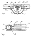
- It 2 shows a partial area of a first embodiment of the window blind 10 according to the invention in vertical section.
- the tension rod 13 comprises this first embodiment of the window blind 10 according to the invention is the at least one pull rod 21 receiving pull strip 16, being in the free ends of the Pull bar 16 closure body 19 receiving the braking device (s) can be used.
- the guide device consists of two the roller blind 12 on their Longitudinal edges flanking essentially vertical guide rails 18, wherein the closure body 19 of the pull bars 16 each enclose a guide rail 18 so that a movement guide given is.
- a braking function can be achieved via this configuration will be realized.
- the braking device consists of the to the guide rails 18 directed ends of the tie rods 21 fixed brake pads 20, see again in particular Fig. 2 of the drawing, the Brake pads 20 each in an opening in the closure bodies 19 are led.
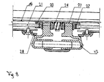
- the brake pads 20 are at these ends of the Drawbars 21 mounted with the help of mounting rings 22, see also Fig. 4 of the drawing.
- On the guide rails 18 opposite ends of the tie rods 21 is a tie rod end cap 23, see again FIG. 2 and also FIG. 3 of the Drawing, with the respective tie rod end cap 23 each a mounting ring 22 is fixed.
- the brake pads 20 can be used to further increase the Friction are overmolded with a thermoplastic elastomer.
- FIG. 3 of the drawing the training of the Actuating element 15 for the connecting member 14 can be seen.
- This actuating element 15 for the at least one tie rod 21 trained connecting member 14 is as a substantially wedge-shaped Slide 26 is formed with inclined surfaces directed towards its center, the corresponding ones formed in the tie rod end caps 23 Counter-sloping surfaces interact. These non-designated counter bevels can be arranged in recordings labeled 27, which are each in the tie rod end caps 23.
- the wedge-shaped slide 26 now causes over the respective slope Pull the tie rod end caps 23 against the one in the middle Compression spring 24, which causes the brake pads 20 to separate from the guide rails 18 solve. By canceling the braking effect Adjustment of light protection possible.
- the inside of the designated 28 Handle housing arranged wedge-shaped slider 26 generated when pressed down in the direction of actuation, with the help a further cylindrical compression spring labeled 29.
- the spring 29 presses this wedge-shaped slide 26 back to the original position. It is a push back or a relief of the between two tie rod end caps 23 mounted compression spring 24 as a cylinder compression spring causes.
- the tie rods 21 and the brake pads then drive 20 apart and the window blind 10 is in the desired Position locked.
- the guide device comprises two the blind web 12 on its longitudinal edges flanking racks 30 and two meshing gears 31, which at the end regions of the Tie rods 21 are arranged, see for example the Embodiment according to FIG. 7 or FIG. 8 of the drawing.
- the window blind according to the invention 10 engages the braking device on at least one of the gear wheels 31 or at least one bearing axle 33 carrying a gear wheel 31.
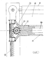
- the alternative embodiment of the window blind 10 according to the invention can be done in different ways. 5 and 6 the embodiment shown in the drawing are the tie rods 21 a toothed rack 30 at the outer end regions encompassing bearing housing 32, each bearing housing 32 a gear 31 arranged in a rotationally fixed manner on a bearing axis 33 carries and at least one of the bearing axes 33 for braking the restoring movement the rewinder equipped with a friction brake is. This friction brake exists, see in particular FIG.
- a friction brake serves in this case as mentioned as a friction brake and consists of a wear-resistant, tough elastic plastic material, such as from a thermoplastic Polyester elastomer. Since the bore of the molded body 34 for receiving an axial area of the bearing axis 33 has an opening cross section has, which is smaller than the cross section of the bearing axis 33, this is Bearing axis 33 sit in this hole like a press fit. This press fit is chosen such that there is still a relative movement between the molded body 34 and the bearing axis 33 is possible and a locking of the window blind 10 by an adjustment of the spring force the winding device and the shaped bodies 34 is effected.
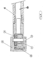
- FIG. 8 of the drawing this alternative variant of the window blind 10 according to the invention.
- at least one of the toothed wheels 31 is adjacent the toothing 37 meshing with the toothed rack 30 has an external toothing 38, in the tooth gaps 39 one under the influence of a Compression spring 42 standing brake body 40 can be locked and by means of a Rack 21 can be disengaged again against the force of the compression spring 42.
- the window blind 10 in particular in production-related with regard to the production tolerances or the possibilities for tolerance compensation compared to the known Embodiments achieved advantages. Furthermore, by the invention Window roller blind 10 the possibilities for locking the Tension rod 13 of this window blind 10 in any position on the Management facility improved.
Landscapes
- Engineering & Computer Science (AREA)
- Structural Engineering (AREA)
- Architecture (AREA)
- Civil Engineering (AREA)
- Mechanical Engineering (AREA)
- Operating, Guiding And Securing Of Roll- Type Closing Members (AREA)
- Blinds (AREA)
Abstract
Description
Die Erfindung bezieht sich auf ein Fensterrollo mit einer eine Aufwickeleinrichtung aufweisenden Wickelwelle, einer auf der Wickelwelle aufgewickelten Rollobahn, einem Zugstab, an dem das freie Ende der Rollobahn befestigt ist, einer Führungseinrichtung, an der die Endbereiche des Zugstabs senkrecht zur Zugstabsachse längsverschiebbar angeordnet sind und einer innerhalb des Zugstabs angeordneten Bremseinrichtung, die lösbar an der Führungseinrichtung angreift, um den Zugstab in beliebigen Positionen an der Führungseinrichtung festzulegen, und einem gegen die Kraft einer Feder verstellbaren, auf die Bremseinrichtung unter Aufhebung der Bremswirkung einwirkenden Verbindungsorgan.The invention relates to a window roller blind with a winding device having winding shaft, one on the winding shaft coiled blind sheet, a tension rod on which the free end of the Roller blind is attached to a guide device on which the end regions of the tension rod is arranged to be longitudinally displaceable perpendicular to the tension rod axis are and a braking device arranged within the tension rod, the releasably engages the guide device to the pull rod in any Determine positions on the management device, and one against the Force adjustable by a spring on the braking device while lifting the braking effect acting connecting element.
Aus dem Stand der Technik sind verschiedene Fensterrollos bekannt, bei denen der Zugstab des Fensterrollos in unterschiedlichen Positionen an dessen Führungseinrichtung festgelegt werden kann.Various window blinds are known from the prior art, at which the pull rod of the window blind in different positions whose management facility can be determined.
Dies kann bei den bekannten Ausführungsformen z. B. über elektromotorisch betriebene Antriebe erfolgen. Es ist aus dem Stand der Technik weiterhin aus der noch nicht veröffentlichten deutschen Patentanmeldung mit dem Aktenzeichen 101 01 436.8-42 ein Fensterrollo bekannt, mit einem gegen die Kraft einer Feder verstellbaren, auf die Bremseinrichtung unter Aufhebung der Bremswirkung einwirkenden Verbindungsorgan. Es ist in diesem Falle dieses Verbindungsorgan aus einem straff geführten Drahtseil gebildet, das einerseits mit die Bremseinrichtung bildenden Bremsklötzen in Wirkverbindung steht und andererseits mit einem mit einer Betätigungseinrichtung verbundenen Stellorgan. Es weist diese bekannte Ausführungsform eines Fensterrollos mit als Drahtseil ausgebildetem Verbindungsorgan an sich ausreichende Funktionseigenschaften auf, es ergeben sich allerdings durch die Ausbildung des als Drahtseil ausgebildeten Verbindungsorgans hinsichtlich der Produktionstoleranzen einige Nachteile. So ergeben sich beispielsweise bei der Verwendung eines Zugseiles Produktionstoleranzen z. B. von ± 3 mm, was zu deren Ausgleich die Verwendung zusätzlicher Funktionselemente wie z. B. einer Feder oder dgl. erforderlich macht. Diese Feder kann z. B. dazu dienen, einen Betätigungshebel von einer waagerechten in eine senkrechte Position zu überführen, da dieser ansonsten für die Bedienperson schlecht oder gar nicht zu erreichen wäre.This can in the known embodiments, for. B. via electric motor operated drives take place. It is state of the art still from the as yet unpublished German patent application with the file number 101 01 436.8-42 a window blind known an adjustable against the force of a spring on the braking device while the braking effect acting on the connecting member. It is in this case this liaison body from a tightly guided Wire rope formed, the one forming the braking device Brake pads are in operative connection and on the other hand with one an actuator connected actuator. It assigns this known embodiment of a window blind with a wire rope trained connecting element sufficient per se Functional properties, but it results from the Training of the connecting element designed as a wire rope with regard the production tolerances some disadvantages. For example when using a pull rope production tolerances such. B. of ± 3 mm, which compensates for the use of additional Functional elements such as B. a spring or the like. Requires. This spring can e.g. B. serve an operating lever of a horizontal to vertical position as this would otherwise be difficult or impossible for the operator to reach.
Ausgehend von diesem bekannten Fensterrollo liegt der Erfindung die Aufgabe zugrunde, die bekannte Anordnung unter Beibehaltung der bisherigen Vorteile in der Weise zu verbessern bzw. weiterzuentwickeln, das sich bezüglich der Produktionstoleranzen bei der Herstellung des gewünschten Fensterrollos deutliche Vorteile ergeben. Die gewünschte Anordnung soll dabei auch einfach und kostengünstig herstellbar sein, und weiterhin hinsichtlich ihrer Funktionseigenschaften den bestehenden Anforderungen vollkommen genügen.Based on this known window roller blind, the invention is the Task based on the known arrangement while maintaining the to improve or develop previous advantages in the way, that differ with regard to the production tolerances in the manufacture of the desired window blinds give clear advantages. The desired Arrangement should also be easy and inexpensive to manufacture, and continue to exist with regard to their functional properties Requirements completely meet.
Die Aufgabe wird erfindungsgemäß dadurch gelöst, dass das verstellbare Verbindungsorgan als wenigstens eine mit der Bremseinrichtung in Wirkverbindung stehende, über ein Betätigungselement beaufschlagbare Zugstange ausgebildet ist. Auf diese Weise wird erstmalig mit einfachen Mitteln ein Fensterrollo geschaffen, das hinsichtlich der Produktionstoleranzen bzw. hinsichtlich des Toleranz-Ausgleiches bezüglich des mit der Bremseinrichtung zusammenwirkenden Verbindungsorganes gegenüber den bekannten Ausführungsformen deutliche Vorteile aufweist. Es ergibt sich durch die Verwendung einer Zugstange für das besagte Verbindungsorgan insbesondere der Vorteil, dass sich für diese Zugstange klar definierte Toleranzen ergeben, so dass unbestimmte Toleranzen ausgeschaltet werden können. Es kann dadurch auch auf zusätzliche Funktionselemente zur Erzielung eines Toleranz-Ausgleiches weitgehend verzichtet werden. Es ergeben sich außerdem durch die Verwendung einer Zugstange in Richtung auf die Führungseinrichtung bessere Möglichkeiten einer kontinuierlichen Druckausübung auf diese Führungseinrichtung, wodurch die Erzielung einer Arretierung an dieser Führungseinrichtung erleichtert wird.The object is achieved in that the adjustable Connecting member as at least one in operative connection with the braking device standing, which can be acted upon by an actuating element Drawbar is formed. This way, for the first time with simple Means created a window roller blind that the production tolerances or with regard to the tolerance compensation with regard to the braking device interacting connecting member the known embodiments has clear advantages. It results through the use of a tie rod for said link in particular the advantage that this tie rod is clear Defined tolerances result, so that indefinite tolerances are switched off can be. This can also lead to additional Functional elements to achieve tolerance compensation largely to be dispensed with. It also results from using a Drawbar towards the guide means better options a continuous pressure on this guide device, whereby achieving a lock on this guide device is facilitated.
Bei der bevorzugten Ausführungsform der vorliegenden Erfindung umfasst der Zugstab eine die wenigstens eine Zugstange aufnehmende Ziehleiste, wobei in die freien Enden der Ziehleiste die Bremseinrichtung(en) aufnehmende Verschlusskörper einsetzbar sind. Es empfiehlt sich dabei, dass die Führungseinrichtung aus zwei die Rollobahn an ihren Längsrändern flankierenden im wesentlichen senkrechten Führungsschienen besteht, wobei die Verschlusskörper der Ziehleiste jeweils eine Führungsschiene umschließen, so dass eine Bewegungsführung gegeben ist. Es bildet dieses eine konstruktiv einfache Ausführungsform des erfindungsgemäßen Fensterrollos.In the preferred embodiment of the present invention the pull rod is a pull bar which receives at least one pull rod, the braking device (s) receiving into the free ends of the drawing strip Closure body can be used. It is recommended that the Guide device consisting of two flanking the roller blind at its longitudinal edges consists essentially of vertical guide rails, the Closure body of the pull strip each enclose a guide rail, so that movement is given. It forms this one structurally simple embodiment of the window blind according to the invention.
Nach einem weiteren Merkmal der vorliegenden Erfindung besteht die Bremseinrichtung aus an den zu den Führungsschienen gerichteten Enden der Zugstangen festgelegten Bremsklötzen, die in jeweils einer Öffnung in den Verschlusskörpern geführt sind. Zweckmäßig ist dabei an den von den Führungsschienen abgewandten Enden der Zugstangen jeweils eine Zugstangenendkappe festgelegt. Es empfiehlt sich dabei, dass im Bereich der Mitte der Ziehleiste zwischen den Zugstangenendkappen eine die Bremsklötze nach außen drückende Druckfeder ausgebildet ist. Es können durch diese Druckfeder die Produktionstoleranzen der wenigstens einen Zugstange zusätzlich ausgeglichen werden.According to a further feature of the present invention Braking device at the ends facing the guide rails of the tie rods set brake pads, each in an opening in the closure bodies are guided. It is useful to the of the Ends of the tie rods facing away from the guide rails each have one Drawbar end cap set. It is recommended that in the area the middle of the pull strip between the tie rod end caps Brake pads pushing outward compression spring is formed. It can through this compression spring the production tolerances of at least one Drawbar can be compensated additionally.
Um eine Sperrung zwischen der Ziehleiste und der Führungseinrichtung zu erreichen, empfiehlt es sich nach einem weiteren Merkmal der vorliegenden Erfindung, dass der Abstand zwischen den Führungsschienen des Fensterrollos geringer ist als der Länge der die Bremseinrichtung, die Zugstangen und die Druckfeder aufnehmenden Ziehleiste.To block between the pull bar and the guide device too achieve, it is recommended according to another feature of the present Invention that the distance between the guide rails of the Window blinds is less than the length of the braking device, the tie rods and the compression spring receiving pull bar.
Nach einem weiteren Merkmal der vorliegenden Erfindung wird vorgeschlagen, dass wenigstens eine der Führungsschienen des Fensterrollos zur Erhöhung der Reibung zwischen Bremseinrichtung und Führungsschiene und damit der Bremswirkung wenigstens einen im wesentlichen längs eingelassenen Elastomerstreifen umfasst.According to a further feature of the present invention, it is proposed that that at least one of the guide rails of the window blind to increase the friction between the braking device and the guide rail and thus the braking effect at least one essentially includes longitudinally embedded elastomer strips.
Zweckmäßig ist es außerdem, dass das Betätigungselement für das als wenigstens eine Zugstange ausgebildete Verbindungsorgan als ein im wesentlichen keilförmiger Schieber mit zu seiner Mitte hin gerichteten Schrägflächen ausgebildet ist, die mit in den Zugstangenendkappen ausgebildeten, entsprechenden Gegenschrägflächen zusammenwirken. Mit diesen Mitteln lässt sich das mit der Bremseinrichtung in Wirkverbindung stehende Verbindungsorgan in geeigneter Weise einfach betätigen.It is also expedient that the actuating element for the at least one tie rod trained connecting member as an im essential wedge-shaped slide with directed towards its center Inclined surfaces is formed, which with formed in the tie rod end caps, corresponding counter-sloping surfaces interact. With These means can be operatively connected to the braking device simply operate the standing connecting element in a suitable manner.
Bei einer alternativen Ausführungsform der vorliegenden Erfindung umfasst die Führungseinrichtung zwei die Rollobahn an ihren Längsrändern flankierende Zahnstangen und zwei damit kämmende Zahnräder, die an den Endbereichen der Zugstangen angeordnet sind. Es kann dabei zweckmäßig die Bremseinrichtung an wenigstens einem der Zahnräder oder wenigstens einer ein Zahnrad tragenden Lagerachse angreifen.In an alternative embodiment of the present invention the guide device comprises two the blind sheet on its longitudinal edges flanking racks and two intermeshing gears the end regions of the tie rods are arranged. It can be useful the braking device on at least one of the gears or attack at least one bearing axle carrying a gearwheel.
Nach einem bevorzugten Ausgestaltungsmerkmal dieser alternativen Ausführungsform der vorliegenden Erfindung ist vorgesehen, dass die Zahnstangen an den äußeren Endbereichen mit einem jeweils eine Zahnstange umgreifenden Lagergehäuse versehen sind, dass jedes Lagergehäuse ein drehfest auf einer Lagerachse angeordnetes Zahnrad trägt und dass zumindest eine der Lagerachsen zum Abbremsen der Rückstellbewegung der Aufwickeleinrichtung mit einer Reibungsbremse ausgerüstet ist, die aus einem gegenüber der Lagerachse verdrehfest im Lagergehäuse angeordneten Formkörper aus verschleißfestem, zähelastischem Kunststoffmaterial besteht, welcher eine Bohrung zur Aufnahme eines axialen Bereiches der Lagerachse aufweist, deren Durchmesser kleiner als der Durchmesser der Lagerachse ausgeführt ist, jedoch eine Relativbewegung zwischen Formkörper und Lagerachse zulässt.According to a preferred design feature of this alternative Embodiment of the present invention provides that the Racks at the outer end areas with one rack each encompassing bearing housings are provided that every bearing housing carries a gear fixedly arranged on a bearing axis and that at least one of the bearing axles to brake the return movement the rewinder equipped with a friction brake is that of a relative to the bearing axis in the bearing housing arranged molded body made of wear-resistant, tough elastic Plastic material is made which has a bore for receiving a Axial region of the bearing axis, the diameter of which is smaller than the diameter of the bearing axis is designed, however one Relative movement between the molded body and the bearing axis allows.
Gemäß einer anderen Ausführungsform dieser alternativen Möglichkeit für die Ausbildung der vorliegenden Erfindung ist vorgehen, dass an unverzahnten Umfangsbereichen der Zahnräder jeweils ein durch jeweils eine Druckfeder belasteter Bremsklotz angreift, wobei die Anordnung der Bremsklötze so getroffen ist, dass sie über die Zugstangen gegen die Kraft der Druckfeder unter Aufhebung der Bremswirkung gegeneinander bewegbar sind.According to another embodiment of this alternative possibility for The design of the present invention is that on toothless Circumferential areas of the gears one by one Pressure spring loaded brake pad attacks, the arrangement of the Brake pads are hit so that they pull over the tie rods against the force the compression spring while canceling the braking effect against each other are movable.
Nach einem weiteren Merkmal dieser alternativen Möglichkeit für die Ausbildung der Erfindung ist vorgesehen, dass zumindest eines der Zahnräder neben der mit Zahnstange kämmenden Verzahnung eine Außenverzahnung aufweist, in deren Zahnlücken ein unter dem Einfluss einer Druckfeder stehender Bremskörper einrastbar und mittels der Zugstangen gegen die Kraft der Druckfeder wieder ausrastbar ist. According to another feature of this alternative possibility for the Embodiment of the invention provides that at least one of the gears in addition to the toothing meshing with toothed rack, an external toothing has, in the tooth spaces under the influence of a Compression spring brake body can be snapped in and by means of the tie rods can be disengaged again against the force of the compression spring.
Nach einem letzten Merkmal der vorliegenden Erfindung ist für einen weiteren Ausgleich der Karosserietoleranzen vorgesehen, dass die Bremseinrichtung aus an den zu den Führungsschienen gerichteten Enden der Zugstangen angeordneten, voneinander entkoppelten Bremselementen besteht.According to a final feature of the present invention, for one further compensation of the body tolerances provided that the Braking device at the ends facing the guide rails of the tie rods arranged, decoupled brake elements consists.
Die Erfindung ist in den Figuren der Zeichnung in mehreren Ausführungsbeispielen dargestellt. Es zeigen:
- Fig. 1
- ein komplettes Fensterrollo in Ansicht,
- Fig. 2
- einen teilweise weggebrochenen Vertikalschnitt durch einen Teilbereich einer ersten Ausführungsform des erfindungsgemäßen Fensterrollos,
- Fig. 3
- einen beidseitig weggebrochenen Vertikalschnitt durch den mittleren Teil der Ziehleiste der Ausführungsform des Fensterrollos nach Fig. 2,
- Fig. 4
- einen weggebrochenen Horizontalschnitt des einen Endbereiches der Ziehleiste der Ausführungsform des Fensterrollos nach Fig. 2,
- Fig. 5
- einen Teilbereich einer alternativen Ausführungsform des Fensterrollos im Vertikalschnitt,
- Fig. 6
- einen Teilbereich des Fensterrollos nach Fig. 5 im Horizontalschnitt,
- Fig. 7
- einen Teilbereich einer abgewandelten alternativen Ausführungsform des erfindungsgemäßen Fensterrollos im Vertikalschnitt,
- Fig. 8
- einen Teilbereich einer weiteren alternativen Ausführungsform des erfindungsgemäßen Fensterrollos im Vertikalschnitt.
- Fig. 9
- einen beidseitig weggebrochenen Vertikalschnitt durch den mittleren Teil der Ziehleiste einer letzten Ausführungsform des erfindungsgemäßen Fensterrollos.
- Fig. 1
- a complete window blind in view,
- Fig. 2
- 3 shows a partially broken vertical section through a partial area of a first embodiment of the window blind according to the invention,
- Fig. 3
- 2 shows a vertical section broken away on both sides through the middle part of the drawing strip of the embodiment of the window blind according to FIG. 2,
- Fig. 4
- 3 shows a broken away horizontal section of one end region of the pull strip of the embodiment of the window blind according to FIG. 2,
- Fig. 5
- a partial area of an alternative embodiment of the window blind in vertical section,
- Fig. 6
- 5 a partial area of the window blind according to FIG. 5 in horizontal section,
- Fig. 7
- a partial area of a modified alternative embodiment of the window blind according to the invention in vertical section,
- Fig. 8
- a partial area of a further alternative embodiment of the window blind according to the invention in vertical section.
- Fig. 9
- a vertical section broken away on both sides through the central part of the pull strip of a last embodiment of the window shade according to the invention.
Das erfindungsgemäße Fensterrollo ist generell mit 10 bezeichnet. Das
Fensterrollo 10 besteht im wesentlichen, siehe dazu zunächst insbesondere
die Fig. 1 der Zeichnung, aus einer eine Aufwickeleinrichtung
aufweisenden Wickelwelle 11, einer darauf auf- und abwickelbar angeordneten
Rollobahn 12, einem Zugstab 13, an dem das freie Ende der
Rollobahn 12 befestigt ist, und einer Führungseinrichtung, an der die
Endbereiche des Zugstabs 13 senkrecht zur Zugstabsachse längsverschiebbar
angeordnet sind.The window blind according to the invention is generally designated 10. The
Window roller blind 10 consists essentially, see first of all in particular
1 of the drawing, from a winding device
having winding
Es besteht dabei die Wickelwelle 11 zweckmäßig aus einem Rohr mit
endseitigen, nicht bezeichneten Verschlusselementen, Drehzapfen 41 und
einer in dem Inneren der Wickelwelle 11, in der Fig. 1 der Zeichnung
lediglich angedeutet dargestellten Aufwickelvorrichtung mit Torsionsfeder
17.There is the winding
Das erfindungsgemäße Fensterrollo 10 umfasst weiterhin eine innerhalb
des Zugstabs 13 angeordnete Bremseinrichtung, die lösbar an der Führungseinrichtung
angreift, um den Zugstab 13 in beliebigen Positionen an
der Führungseinrichtung festzulegen, das Fensterrollo 10 umfasst weiterhin
ein gegen die Kraft einer Feder verstellbares, auf die Bremseinrichtung
unter Aufhebung der Bremswirkung einwirkendes Verbindungsorgan 14,
siehe z. B. die Fig. 2 der Zeichnung.The window blind 10 according to the invention further comprises an inside
of the
Das verstellbare Verbindungsorgan 14 ist erfindungsgemäß als wenigstens
eine mit der Bremseinrichtung in Wirkverbindung stehende, über ein
Betätigungselement 15 beaufschlagbare Zugstange 21 ausgebildet. Es
zeigt dazu die Fig. 2 der Zeichnung einen Teilbereich einer ersten Ausführungsform
des erfindungsgemäßen Fensterrollos 10 im Vertikalschnitt.
In diesem Falle umfasst der Zugstab 13 dieser ersten Ausführungsform
des erfindungsgemäßen Fensterrollos 10 eine die wenigstens eine Zugstange
21 aufnehmende Ziehleiste 16, wobei in die freien Enden der
Ziehleiste 16 die Bremseinrichtung(en) aufnehmende Verschlusskörper 19
einsetzbar sind. Bei dieser Ausführungsform gemäß der Fig. 2 der Zeichnung
besteht die Führungseinrichtung aus zwei die Rollobahn 12 an ihren
Längsrändern flankierenden im wesentlichen senkrechten Führungsschienen
18, wobei die Verschlusskörper 19 der Ziehleisten 16 jeweils
eine Führungsschiene 18 umschließen, so dass eine Bewegungsführung
gegeben ist. Gleichzeitig kann über diese Ausgestaltung eine Bremsfunktion
realisiert werden.The adjustable connecting
Die Bremseinrichtung besteht dabei aus an den zu den Führungsschienen
18 gerichteten Enden der Zugstangen 21 festgelegten Bremsklötzen 20,
siehe dazu wiederum insbesondere die Fig. 2 der Zeichnung, wobei die
Bremsklötze 20 in jeweils einer Öffnung in den Verschlusskörpern 19
geführt sind. Die Bremsklötze 20 werden dabei an diesen Enden der
Zugstangen 21 mit Hilfe von Befestigungsringen 22 montiert, siehe dazu
auch die Fig. 4 der Zeichnung. An den von den Führungsschienen 18
abgewandten Enden der Zugstangen 21 ist jeweils eine Zugstangenendkappe
23 festgelegt, siehe wieder die Fig. 2 sowie auch die Fig. 3 der
Zeichnung, wobei die jeweilige Zugstangenendkappe 23 jeweils durch
einen Befestigungsring 22 fixiert wird.The braking device consists of the to the guide rails
18 directed ends of the
Im Bereich der Mitte der Ziehleiste 16 ist, siehe insbesondere die Fig. 3
der Zeichnung, zwischen den Zugstangenendkappen 23 eine die Bremsklötze
20 nach außen drückende Druckfeder 24, insbesondere Zylinderdruckfeder,
ausgebildet. Um eine Sperrung zwischen der Ziehleiste 16 und
den Führungsschienen 18 zu erzeugen, ist der Abstand zwischen den
Führungsschienen 18 des Fensterrollos 10 geringer als die Länge der die
Bremseinrichtung, die Zugstangen 21 und die Druckfeder 24 aufnehmenden
Ziehleiste. Es hat dies zur Folge, dass die Druckfeder 24, wie
Zylinderdruckfeder, ständig unter Kompression gehalten wird. Die Bremsklötze
20 werden demzufolge auf die Führungsschienen 18 nach außen
gedrückt und erzeugen somit eine Sperre zwischen der Ziehleiste 16 und
den Führungsschienen 18. Es umfasst dabei wenigstens eine der
Führungsschienen 18 des Fensterrollos 10 zur Erhöhung der Reibung
zwischen Bremseinrichtung, d. h. den Bremsklötzen 20, und der Führungsschiene
18 und damit der Bremswirkung wenigstens einen im wesentlichen
längs eingelassenen Elastomerstreifen 25, siehe dazu wieder die
Fig. 2 sowie auch insbesondere die Fig. 4 der Zeichnung. In Abwandlung
dazu können ergänzend die Bremsklötze 20 zur weiteren Erhöhung der
Reibung mit einem thermoplastischen Elastomer überspritzt werden.In the area of the center of the
In der Fig. 3 der Zeichnung ist insbesondere die Ausbildung des
Betätigungselementes 15 für das Verbindungsorgan 14 zu entnehmen.
Dieses Betätigungselement 15 für das als wenigstens eine Zugstange 21
ausgebildete Verbindungsorgan 14 ist als ein im wesentlichen keilförmiger
Schieber 26 mit zu seiner Mitte hin gerichteten Schrägflächen ausgebildet,
die mit in den Zugstangenendkappen 23 ausgebildeten entsprechenden
Gegenschrägflächen zusammenwirken. Diese nichtbezeichneten Gegenschrägflächen
können in mit 27 bezeichneten Aufnahmen angeordnet sein,
die sich jeweils in den Zugstangenendkappen 23 befinden.In Fig. 3 of the drawing, the training of the
Der keilförmige Schieber 26 bewirkt nun über die jeweilige Schräge ein
Zusammenziehen der Zugstangenendkappen 23 gegen die mittig sitzende
Druckfeder 24, wodurch die Bremsklötze 20 sich von den Führungsschienen
18 lösen. Durch diese Aufhebung der Bremswirkung wird eine
Verstellung des Lichtschutzes möglich. Der innerhalb des mit 28 bezeichneten
Griffgehäuses angeordnete keilförmige Schieber 26 erzeugt,
wenn er in der Betätigungsrichtung nach unten gedrückt wird, mit Hilfe
einer mit 29 bezeichneten weiteren zylindrischen Druckfeder Widerstand.
Sobald der keilförmige Schieber 26 entlastet wird, drückt die Feder 29
diesen keilförmigen Schieber 26 auf die ursprüngliche Position zurück. Es
wird dadurch ein Zurückschieben bzw. eine Entlastung der zwischen den
beiden Zugstangenendkappen 23 gelagerten Druckfeder 24 wie Zylinderdruckfeder
bewirkt. Es fahren dann die Zugstangen 21 bzw. die Bremsklötze
20 auseinander und das Fensterrollo 10 wird in der gewünschten
Position gesperrt.The wedge-shaped
In den Fig. 5 bis 8 der Zeichnung ist eine alternative Ausgestaltungsform
des erfindungsgemäßen Fensterrollos 10 in verschiedenen Ausgestaltungsformen
dargestellt. In diesem Falle umfasst die Führungseinrichtung zwei
die Rollobahn 12 an ihren Längsrändern flankierende Zahnstangen 30 und
zwei damit kämmende Zahnräder 31, die an den Endbereichen der
Zugstangen 21 angeordnet sind, siehe dazu beispielsweise die
Ausführungsform gemäß der Fig. 7 oder der Fig. 8 der Zeichnung. Bei
dieser alternativen Ausführungsform des erfindungsgemäßen Fensterrollos
10 greift die Bremseinrichtung an wenigstens einem der Zahnräder 31
oder wenigstens eine ein Zahnrad 31 tragenden Lagerachse 33 an.5 to 8 of the drawing is an alternative embodiment
of the window blind 10 according to the invention in various configurations
shown. In this case, the guide device comprises two
the
Die alternative Ausführungsform des erfindungsgemäßen Fensterrollos 10
lässt sich auf verschiedene Weisen ausführen. Bei dem in den Fig. 5 und 6
der Zeichnung dargestellten Ausführungsbeispiel sind die Zugstangen 21
an den äußeren Endbereichen mit einem jeweils eine Zahnstange 30
umgreifenden Lagergehäuse 32 versehen, wobei jedes Lagergehäuse 32
ein drehfest auf einer Lagerachse 33 angeordnetes Zahnrad 31 trägt und
wobei zumindest eine der Lagerachsen 33 zum Abbremsen der Rückstellbewegung
der Aufwickeleinrichtung mit einer Reibungsbremse ausgerüstet
ist. Diese Reibungsbremse besteht, siehe insbesondere die Fig. 6
der Zeichnung, aus einem gegenüber der Lagerachse 33 verdrehfest im
Lagergehäuse 32 angeordneten Formkörper 34 aus verschleißfestem,
zähelastischem Kunststoffmaterial, wobei der Formkörper 34 eine Bohrung
zur Aufnahme eines axialen Bereiches der Lagerachse 33 aufweist, deren
Durchmesser kleiner als der Durchmesser der Lagerachse 33 ausgeführt
ist, jedoch eine Relativbewegung zwischen Formkörper 34 und Lagerachse
33 zulässt. Bei dieser Ausführungsform wird das Zahnrad 31 mit der Verzahnung
der Zahnstange 30 kämmen, wie auch das am anderen Ende der
Ziehleiste 16 befindliche zweite Zahnrad 31 mit der zugehörigen Verzahnung
der zweiten Zahnstange 30 kämmen wird, so dass der Zugstab
13 beim Abziehen der Rollobahn 12 von der Wickelwelle 11 nicht
verkanten kann. Der aus der Fig. 6 ersichtliche Formkörper 34 dient dabei
wie erwähnt als Reibungsbremse und besteht aus einem verschleißfesten,
zähelastischen Kunststoffmaterial, wie aus einem thermoplastischen
Polyesterelastomer. Da die Bohrung des Formkörpers 34 zur Aufnahme
eines axialen Bereiches der Lagerachse 33 einen Öffnungsquerschnitt
aufweist, der kleiner ist als der Querschnitt der Lagerachse 33, wird diese
Lagerachse 33 nach Art einer Presspassung in dieser Bohrung sitzen.
Diese Presspassung ist dabei derart gewählt, dass noch eine Relativbewegung
zwischen dem Formkörper 34 und Lagerachse 33 möglich ist und
eine Arretierung des Fensterrollos 10 durch eine Angleichung der Federkraft
der Aufwickelvorrichtung und den Formkörpern 34 bewirkt wird.The alternative embodiment of the window blind 10 according to the invention
can be done in different ways. 5 and 6
the embodiment shown in the drawing are the tie rods 21
a
Bei der Ausführungsform des erfindungsgemäßen Fensterrollos 10 nach
der Fig. 7 der Zeichnung greift an unverzahnten Umfangsbereichen 36 der
Zahnräder 31 jeweils ein durch jeweils eine Druckfeder 42 belasteter
Bremsklotz 20 an, wobei die Anordnung der Bremsklötze 20 so getroffen
ist, dass sie über durch das Lagergehäuse 32 hindurchgeführte
Zugstangen 21 gegen die Kraft der Druckfeder 42 unter Aufhebung der
Bremswirkung gegeneinander bewegbar sind. Bei dieser Ausführungsform
sind also wieder in die Enden der Ziehleiste 16 Lagergehäuse 32 eingesetzt,
die jeweils zur Lagerung einer Lagerachse 33 und eines Zahnrades
31 dienen und die jeweils ähnlich, wie in Fig. 6 dargestellt, eine Zahnstange
30 umgreifen. Die Zahnräder 31 weisen jeweils einen verzahnten
Umfangsbereich auf, der mit den Zahnstangen 30 zusammenwirkt und
daneben auch einen unverzahnten Umfangsbereich 36, der mit den
Bremsklötzen 20 zusammenwirkt. Die Ausbildung der Bremseinrichtung,
die Wirkungsweise der Bremse sowie die Aufhebung der Bremswirkung
zum Verstellen der Rollobahn 12 entspricht im übrigen der Ausführungsform
der Fig. 5 der Zeichnung.In the embodiment of the window blind 10 according to the invention
7 of the drawing engages on toothless
In der Fig. 8 der Zeichnung ist schließlich eine weitere Ausführungsform
dieser alternativen Variante des erfindungsgemäßen Fensterrollos 10 dargestellt.
In diesem Falle weist zumindest eines der Zahnräder 31 neben
der mit der Zahnstange 30 kämmenden Verzahnung 37 eine Außenverzahnung
38 auf, in deren Zahnlücken 39 ein unter dem Einfluss einer
Druckfeder 42 stehender Bremskörper 40 einrastbar und mittels einer
Zahnstange 21 gegen die Kraft der Druckfeder 42 wieder ausrastbar ist.Finally, another embodiment is shown in FIG. 8 of the drawing
this alternative variant of the window blind 10 according to the invention.
In this case, at least one of the
In der Fig. 9 der Zeichnung ist eine letzte Ausführungsform des
erfindungsgemäßen Fensterrollos 10 dargestellt. In diesem Falle besteht
die Bremseinrichtung aus an den zu den Führungsschienen 18 gerichteten
Enden der Zugstangen 21 angeordneten, voneinander entkoppelten
Bremselementen, in diesem Falle Bremsklötzen 20. Diese Entkopplung der
Bremselemente bewirkt einen weiteren Ausgleich der
Karosserietoleranzen. Es.wird dabei bewirkt, dass jedes Bremselement, d.
h. hier jeder Bremsklotz 20 auf die Führungsschiene 18, unabhängig
voneinander, nach außen gedrückt und somit eine Sperre zwischen der
Ziehleiste 16 und den Führungsschienen 18 erzeugt wird. Um die
Sperrung aufzuheben, werden die Zugstangenendkappen 23, wie
dargestellt mit einem an den Zugstangenendklappen 23 angesetzten Hebel
43 zusammengedrückt, wobei dieser in Aufnahmen 27 in den
Zugstangenendkappen 23 eingreift. Dies hat zur Folge, dass die
zylindrische Druckfeder 24 unter Kompression gesetzt wird und die
Bremsklötze 20 sich von den Führungsschienen 18 lösen.9 of the drawing is a last embodiment of the
Window blinds 10 according to the invention shown. In this case there is
the braking device from the directed towards the guide rails 18
Ends of the
Durch das erfindungsgemäße Fensterrollo 10 werden insbesondere in
produktionstechnischer Hinsicht bezüglich der Produktionstoleranzen bzw.
der Möglichkeiten für einen Toleranz-Ausgleich gegenüber den bekannten
Ausführungsformen Vorteile erreicht. Weiterhin werden durch das erfindungsgemäße
Fensterrollo 10 die Möglichkeiten für eine Arretierung des
Zugstabes 13 dieses Fensterrollos 10 in beliebigen Positionen an der
Führungseinrichtung verbessert.The window blind 10 according to the invention in particular in
production-related with regard to the production tolerances or
the possibilities for tolerance compensation compared to the known
Embodiments achieved advantages. Furthermore, by the invention
Window roller blind 10 the possibilities for locking the
Wie bereits erwähnt, sind die dargestellten Ausführungsformen nur beispielsweise Verwirklichungen der Erfindung, diese ist nicht darauf beschränkt, es sind vielmehr noch mancherlei Abänderungen und Ausbildungen möglich. So sind insbesondere Abwandlungen hinsichtlich der Ausführung der Führungseinrichtung sowie auch der lösbar an dieser angreifenden Bremseinrichtung möglich, weiterhin denkbar sind auch Variationen bezüglich der Ausbildung des als Zugstange ausgebildeten verstellbaren Verbindungsorganes. As already mentioned, the illustrated embodiments are only examples Realizations of the invention, this is not limited to rather, there are still various modifications and training courses possible. So are modifications in particular Execution of the guide device and also releasably on this attacking braking device possible, are also conceivable Variations in the design of the pull rod adjustable connecting member.
- 1010
- Fensterrollowindow blind
- 1111
- Wickelwellewinding shaft
- 1212
- Rollobahnblind web
- 1313
- Zugstabtension rod
- 1414
- Verbindungsorganconnecting member
- 1515
- Betätigungselementactuator
- 1616
- Ziehleistepull bar
- 1717
- Torsionsfedertorsion spring
- 1818
- Führungsschieneguide rail
- 1919
- Verschlusskörper (in 21)Closure body (in 21)
- 2020
- Bremsklotzbrake pad
- 2121
- Zugstangepull bar
- 2222
- Befestigungsring (an 21)Mounting ring (on 21)
- 2323
- ZugstangenendkappeZugstangenendkappe
- 2424
- Druckfedercompression spring
- 2525
- Elastomerstreifen (an 18)Elastomer strips (on 18)
- 2626
- Keilförmiger SchieberWedge-shaped slide
- 2727
- Aufnahme (in 23 für 26)Recording (in 23 for 26)
- 2828
- Griffgehäusehandle housing
- 2929
- Druckfedercompression spring
- 3030
- Zahnstangerack
- 3131
- Zahnradgear
- 3232
- Lagergehäusebearing housing
- 3333
- Lagerachsebearing axle
- 3434
- Formkörpermoldings
- 3636
- Unverzahnter Umfangsbereich (von 31)Tooth-free peripheral area (from 31)
- 3737
- Kämmende Verzahnung (von 31 an 30)Intermeshing teeth (from 31 to 30)
- 3838
- Außenverzahnung (von 31)External teeth (from 31)
- 3939
- Zahnlücke (von 38) Tooth gap (from 38)
- 4040
- BremskörperBrakes
- 4141
- Drehzapfenpivot
- 4242
- Druckfeder (an 20, 40)Compression spring (on 20, 40)
- 4343
- Hebel (an 23 angreifend)Lever (attacking 23)
Claims (15)
dadurch gekennzeichnet, dass das verstellbare Verbindungsorgan (14) als wenigstens eine mit der Bremseinrichtung in Wirkverbindung stehende, über ein Betätigungselement (15) beaufschlagbare Zugstange (21) ausgebildet ist.Window roller blind (10) with a winding shaft (11) having a winding device, a roller blind web (12) wound on the winding shaft (11), a pull rod (13) to which the free end of the roller blind web (12) is fastened, a guide device the end regions of the tension rod (13) are arranged so as to be longitudinally displaceable perpendicular to the axis of the tension rod, and a braking device arranged inside the tension rod (13), which detachably engages the guide device in order to fix the tension rod (13) in any positions on the guide device, and one against the Force of a spring adjustable connecting element (14) acting on the braking device while canceling the braking effect,
characterized in that the adjustable connecting member (14) is designed as at least one pull rod (21) which is operatively connected to the braking device and can be acted upon by an actuating element (15).
Applications Claiming Priority (2)
| Application Number | Priority Date | Filing Date | Title |
|---|---|---|---|
| DE2002116363 DE10216363B4 (en) | 2002-04-13 | 2002-04-13 | window blind |
| DE10216363 | 2002-04-13 |
Publications (2)
| Publication Number | Publication Date |
|---|---|
| EP1353037A2 true EP1353037A2 (en) | 2003-10-15 |
| EP1353037A3 EP1353037A3 (en) | 2005-09-14 |
Family
ID=28051296
Family Applications (1)
| Application Number | Title | Priority Date | Filing Date |
|---|---|---|---|
| EP03003014A Withdrawn EP1353037A3 (en) | 2002-04-13 | 2003-02-12 | Window roller blind |
Country Status (3)
| Country | Link |
|---|---|
| EP (1) | EP1353037A3 (en) |
| DE (1) | DE10216363B4 (en) |
| PL (1) | PL211752B1 (en) |
Cited By (11)
| Publication number | Priority date | Publication date | Assignee | Title |
|---|---|---|---|---|
| EP1803599A1 (en) | 2005-12-28 | 2007-07-04 | Grupo Antolin-Ingenieria, S.A. | Shading device for vehicle roofs with a transparent element and method of locking said device |
| EP1852286A1 (en) * | 2006-05-02 | 2007-11-07 | ArvinMeritor GmbH | Coupling device for a roller blind and roller blind system for a vehicle roof |
| CN103122747A (en) * | 2011-11-18 | 2013-05-29 | 皇田工业股份有限公司 | Track type sun shading device |
| EP2826944A3 (en) * | 2013-07-17 | 2015-08-19 | Hunter Douglas Inc. | Handle and brake arrangement for a covering for architectural openings |
| WO2016070278A1 (en) * | 2014-11-06 | 2016-05-12 | Axis Labs Inc. | Adjustable mounting system for window blinds and shades |
| CN107044254A (en) * | 2017-06-06 | 2017-08-15 | 海宁市亚铝装饰材料有限公司 | A kind of screen window positioning and the anti-elastic system of backrush |
| US10173312B2 (en) | 2012-02-28 | 2019-01-08 | Hunter Douglas Industries B.V. | Architectural covering with repositionable handle assembly |
| USD842677S1 (en) | 2016-02-17 | 2019-03-12 | Hunter Douglas Inc. | Handle for a covering for an architectural opening |
| US10487572B2 (en) | 2016-01-25 | 2019-11-26 | Hunter Douglas Inc. | Pivotable handle for an architectural covering |
| US10494861B2 (en) | 2016-02-17 | 2019-12-03 | Hunter Douglas Inc. | Handle assembly for an architectural opening |
| US11199048B2 (en) | 2016-01-25 | 2021-12-14 | Hunter Douglas Inc. | Handle structure and assembly for bottom rail of window shading |
Families Citing this family (3)
| Publication number | Priority date | Publication date | Assignee | Title |
|---|---|---|---|---|
| DE102008015926A1 (en) * | 2008-03-27 | 2009-10-01 | Happich Fahrzeug- Und Industrieteile Gmbh | Rollo facility |
| DE102009008490A1 (en) * | 2009-02-11 | 2010-08-12 | Happich Fahrzeug- Und Industrieteile Gmbh | Roller blind device, has braking device engaging at guiding device by friction effect to fix bar at guiding device in any positions and designed as brake pad-brake shoe-unit with adjusting device to adjust friction force of braking device |
| US9708850B2 (en) | 2013-07-17 | 2017-07-18 | Hunter Douglas Inc. | Arrangement for mounting an actuator button onto a rail of a window covering |
Citations (8)
| Publication number | Priority date | Publication date | Assignee | Title |
|---|---|---|---|---|
| US849133A (en) * | 1903-04-28 | 1907-04-02 | Curtain Supply Co | Shade-holding device. |
| US1299986A (en) * | 1917-12-08 | 1919-04-08 | Eugene G Mattison | Wind-shield shade. |
| US1659834A (en) * | 1927-03-19 | 1928-02-21 | Raymond E Pippin | Adjustable shade-roller support |
| EP0254896A2 (en) * | 1986-07-26 | 1988-02-03 | Eugen Seitz | Roll-screen for mobil-home window |
| DE8717270U1 (en) * | 1987-04-07 | 1988-05-26 | Kress, Peter, Dipl.-Ing., 8524 Dormitz, De | |
| DE4200422A1 (en) * | 1992-01-10 | 1993-07-15 | Remis Gmbh | Roller-blind lockable at different heights - has toothed component on bottom bar movable in and out of engagement with racks at sides |
| DE4301028A1 (en) * | 1993-01-16 | 1994-07-21 | Iveco Magirus | Roller-shutter closure device |
| DE9417613U1 (en) * | 1994-11-03 | 1995-01-05 | Wilhelm Dietmar | Fastening system for window darkening or the like. |
Family Cites Families (2)
| Publication number | Priority date | Publication date | Assignee | Title |
|---|---|---|---|---|
| DE3631919A1 (en) * | 1986-09-19 | 1988-04-07 | Gardinia Vorhangschinenfab | Guide device for folding curtains |
| DE10101436A1 (en) * | 2000-10-24 | 2002-05-02 | Happich Fahrzeug & Ind Teile | window blind |
-
2002
- 2002-04-13 DE DE2002116363 patent/DE10216363B4/en not_active Expired - Fee Related
-
2003
- 2003-02-12 EP EP03003014A patent/EP1353037A3/en not_active Withdrawn
- 2003-03-31 PL PL359441A patent/PL211752B1/en not_active IP Right Cessation
Patent Citations (8)
| Publication number | Priority date | Publication date | Assignee | Title |
|---|---|---|---|---|
| US849133A (en) * | 1903-04-28 | 1907-04-02 | Curtain Supply Co | Shade-holding device. |
| US1299986A (en) * | 1917-12-08 | 1919-04-08 | Eugene G Mattison | Wind-shield shade. |
| US1659834A (en) * | 1927-03-19 | 1928-02-21 | Raymond E Pippin | Adjustable shade-roller support |
| EP0254896A2 (en) * | 1986-07-26 | 1988-02-03 | Eugen Seitz | Roll-screen for mobil-home window |
| DE8717270U1 (en) * | 1987-04-07 | 1988-05-26 | Kress, Peter, Dipl.-Ing., 8524 Dormitz, De | |
| DE4200422A1 (en) * | 1992-01-10 | 1993-07-15 | Remis Gmbh | Roller-blind lockable at different heights - has toothed component on bottom bar movable in and out of engagement with racks at sides |
| DE4301028A1 (en) * | 1993-01-16 | 1994-07-21 | Iveco Magirus | Roller-shutter closure device |
| DE9417613U1 (en) * | 1994-11-03 | 1995-01-05 | Wilhelm Dietmar | Fastening system for window darkening or the like. |
Cited By (14)
| Publication number | Priority date | Publication date | Assignee | Title |
|---|---|---|---|---|
| EP1803599A1 (en) | 2005-12-28 | 2007-07-04 | Grupo Antolin-Ingenieria, S.A. | Shading device for vehicle roofs with a transparent element and method of locking said device |
| EP1852286A1 (en) * | 2006-05-02 | 2007-11-07 | ArvinMeritor GmbH | Coupling device for a roller blind and roller blind system for a vehicle roof |
| CN103122747A (en) * | 2011-11-18 | 2013-05-29 | 皇田工业股份有限公司 | Track type sun shading device |
| US10173312B2 (en) | 2012-02-28 | 2019-01-08 | Hunter Douglas Industries B.V. | Architectural covering with repositionable handle assembly |
| EP2826944A3 (en) * | 2013-07-17 | 2015-08-19 | Hunter Douglas Inc. | Handle and brake arrangement for a covering for architectural openings |
| US9926740B2 (en) | 2014-11-06 | 2018-03-27 | AXIS Labs, Inc. | Adjustable mounting system for window blinds and shades |
| WO2016070278A1 (en) * | 2014-11-06 | 2016-05-12 | Axis Labs Inc. | Adjustable mounting system for window blinds and shades |
| CN110344741A (en) * | 2014-11-06 | 2019-10-18 | 艾西斯实验有限公司 | Adjustable installation system for window blind and window-blind |
| US11035171B2 (en) | 2014-11-06 | 2021-06-15 | Ryse Inc. | Adjustable mounting system for window blinds and shades |
| US10487572B2 (en) | 2016-01-25 | 2019-11-26 | Hunter Douglas Inc. | Pivotable handle for an architectural covering |
| US11199048B2 (en) | 2016-01-25 | 2021-12-14 | Hunter Douglas Inc. | Handle structure and assembly for bottom rail of window shading |
| USD842677S1 (en) | 2016-02-17 | 2019-03-12 | Hunter Douglas Inc. | Handle for a covering for an architectural opening |
| US10494861B2 (en) | 2016-02-17 | 2019-12-03 | Hunter Douglas Inc. | Handle assembly for an architectural opening |
| CN107044254A (en) * | 2017-06-06 | 2017-08-15 | 海宁市亚铝装饰材料有限公司 | A kind of screen window positioning and the anti-elastic system of backrush |
Also Published As
| Publication number | Publication date |
|---|---|
| DE10216363A1 (en) | 2003-11-06 |
| PL359441A1 (en) | 2003-10-20 |
| DE10216363B4 (en) | 2006-03-30 |
| PL211752B1 (en) | 2012-06-29 |
| EP1353037A3 (en) | 2005-09-14 |
Similar Documents
| Publication | Publication Date | Title |
|---|---|---|
| DE2750904C2 (en) | Window regulators, in particular for motor vehicles | |
| EP1353037A2 (en) | Window roller blind | |
| EP1190651A2 (en) | Adjusting device for sleeping or seating furniture with at least one swivel part connected by a torsion bar to the sleeping or seating furniture | |
| DE202005002585U1 (en) | Linear motor drive, has brake system with bushing, which is firmly attached to projections on guide flange that is fixed to spindle nut when switch cam actuates limit switch in flange pipe to switch off DC motor | |
| DE202005008151U1 (en) | Drive arrangement for adjustable functional elements in a motor vehicle | |
| DE102005007205B3 (en) | Electromotor linear drive e.g. for adjustment functions, has rotary spindle nut with linear speed components of displacing tube controlled by braking arrangement | |
| EP0941889B1 (en) | Extraction device | |
| EP1201473A2 (en) | Roller blind | |
| WO2017125555A1 (en) | Actuator with a rigid-spined chain | |
| DE2913885A1 (en) | SLATER BLINDS WITH VERTICAL SLATS | |
| EP2154009A1 (en) | Turnbuckle | |
| DE202014100778U1 (en) | Actuation device for a parking brake | |
| DE19619474A1 (en) | Roller-blind for window between body pillars, especially of private motor vehicle | |
| DE102006007072B3 (en) | Device for mechanical release of motor-operated parking brake for motor vehicle has drive mechanism between cage and drive shaft designed so that their relative movement effects rotation of drive shaft in first rotational direction | |
| WO2000037819A1 (en) | Transmission-like device for actuating brake shoes | |
| DE202004021544U1 (en) | Drive for a winding arrangement of a blind | |
| WO2014001032A1 (en) | Drive for the motorized adjustment of an adjusting element of a motor vehicle | |
| DE102005031979A1 (en) | Roller shutter unit has eccentric brakes at ends of extension rod and engaging on side guides to be cleared by actuating element which is fixed together with free end of roller panel on perimeter of extension rod | |
| EP0204862B1 (en) | Sunroof for vehicles | |
| EP0508112A2 (en) | Roller shutter | |
| DE1555178C3 (en) | Window crank for motor vehicles with pull-out handle | |
| CH669571A5 (en) | Railway goods-vehicle brake unit indicator | |
| DE3404124C2 (en) | ||
| EP1200695B1 (en) | Transmission housing | |
| DE10101436A1 (en) | window blind |
Legal Events
| Date | Code | Title | Description |
|---|---|---|---|
| PUAI | Public reference made under article 153(3) epc to a published international application that has entered the european phase |
Free format text: ORIGINAL CODE: 0009012 |
|
| AK | Designated contracting states |
Kind code of ref document: A2 Designated state(s): AT BE BG CH CY CZ DE DK EE ES FI FR GB GR HU IE IT LI LU MC NL PT SE SI SK TR |
|
| AX | Request for extension of the european patent |
Extension state: AL LT LV MK RO |
|
| PUAL | Search report despatched |
Free format text: ORIGINAL CODE: 0009013 |
|
| AK | Designated contracting states |
Kind code of ref document: A3 Designated state(s): AT BE BG CH CY CZ DE DK EE ES FI FR GB GR HU IE IT LI LU MC NL PT SE SI SK TR |
|
| AX | Request for extension of the european patent |
Extension state: AL LT LV MK RO |
|
| RIC1 | Information provided on ipc code assigned before grant |
Ipc: 7E 06B 9/90 B Ipc: 7B 60J 1/20 B Ipc: 7E 06B 9/88 A |
|
| 17P | Request for examination filed |
Effective date: 20050926 |
|
| AKX | Designation fees paid |
Designated state(s): AT BE BG CH CY CZ DE DK EE ES FI FR GB GR HU IE IT LI LU MC NL PT SE SI SK TR |
|
| 17Q | First examination report despatched |
Effective date: 20100804 |
|
| 19U | Interruption of proceedings before grant |
Effective date: 20091001 |
|
| 19W | Proceedings resumed before grant after interruption of proceedings |
Effective date: 20120601 |
|
| RAP1 | Party data changed (applicant data changed or rights of an application transferred) |
Owner name: HAPPICH GMBH |
|
| STAA | Information on the status of an ep patent application or granted ep patent |
Free format text: STATUS: THE APPLICATION IS DEEMED TO BE WITHDRAWN |
|
| 18D | Application deemed to be withdrawn |
Effective date: 20130903 |