EP1345656B1 - Apparatus for alleviation of symptoms by application of tinted light - Google Patents
Apparatus for alleviation of symptoms by application of tinted light Download PDFInfo
- Publication number
- EP1345656B1 EP1345656B1 EP01271246A EP01271246A EP1345656B1 EP 1345656 B1 EP1345656 B1 EP 1345656B1 EP 01271246 A EP01271246 A EP 01271246A EP 01271246 A EP01271246 A EP 01271246A EP 1345656 B1 EP1345656 B1 EP 1345656B1
- Authority
- EP
- European Patent Office
- Prior art keywords
- illumination
- spectral
- observer
- subject
- light sources
- Prior art date
- Legal status (The legal status is an assumption and is not a legal conclusion. Google has not performed a legal analysis and makes no representation as to the accuracy of the status listed.)
- Expired - Lifetime
Links
- 208000024891 symptom Diseases 0.000 title claims abstract description 7
- 238000005286 illumination Methods 0.000 claims abstract description 31
- 230000000007 visual effect Effects 0.000 claims abstract description 19
- 238000000034 method Methods 0.000 claims abstract description 15
- 239000000203 mixture Substances 0.000 claims abstract description 15
- 238000009472 formulation Methods 0.000 claims abstract description 6
- 230000007547 defect Effects 0.000 claims abstract description 5
- 230000001575 pathological effect Effects 0.000 claims abstract description 5
- 238000003745 diagnosis Methods 0.000 claims abstract 2
- 230000003595 spectral effect Effects 0.000 claims description 38
- 230000004044 response Effects 0.000 claims description 11
- 238000001228 spectrum Methods 0.000 claims description 11
- 238000009826 distribution Methods 0.000 claims description 6
- 239000000463 material Substances 0.000 claims description 6
- 238000001429 visible spectrum Methods 0.000 claims description 6
- 238000000411 transmission spectrum Methods 0.000 claims description 4
- 230000005540 biological transmission Effects 0.000 claims description 3
- 238000000985 reflectance spectrum Methods 0.000 claims description 3
- 208000037265 diseases, disorders, signs and symptoms Diseases 0.000 claims description 2
- 230000002207 retinal effect Effects 0.000 claims description 2
- 238000004088 simulation Methods 0.000 claims description 2
- 239000000654 additive Substances 0.000 claims 2
- 230000000996 additive effect Effects 0.000 claims 2
- 238000000576 coating method Methods 0.000 claims 2
- 239000011248 coating agent Substances 0.000 claims 1
- 230000002301 combined effect Effects 0.000 claims 1
- 206010013932 dyslexia Diseases 0.000 abstract description 8
- 208000019695 Migraine disease Diseases 0.000 abstract description 5
- 206010027599 migraine Diseases 0.000 abstract description 4
- 208000002780 macular degeneration Diseases 0.000 abstract description 3
- 230000000694 effects Effects 0.000 description 10
- 230000006870 function Effects 0.000 description 8
- 239000003086 colorant Substances 0.000 description 6
- 230000035945 sensitivity Effects 0.000 description 5
- 230000000638 stimulation Effects 0.000 description 5
- 230000008859 change Effects 0.000 description 4
- 238000000295 emission spectrum Methods 0.000 description 4
- 210000001525 retina Anatomy 0.000 description 4
- 230000001419 dependent effect Effects 0.000 description 2
- 206010015037 epilepsy Diseases 0.000 description 2
- 238000005259 measurement Methods 0.000 description 2
- 208000002177 Cataract Diseases 0.000 description 1
- 206010047531 Visual acuity reduced Diseases 0.000 description 1
- 230000009471 action Effects 0.000 description 1
- 230000002411 adverse Effects 0.000 description 1
- 238000004458 analytical method Methods 0.000 description 1
- 238000000149 argon plasma sintering Methods 0.000 description 1
- 230000008901 benefit Effects 0.000 description 1
- 238000012505 colouration Methods 0.000 description 1
- 230000003247 decreasing effect Effects 0.000 description 1
- 230000006735 deficit Effects 0.000 description 1
- 238000010586 diagram Methods 0.000 description 1
- 208000035475 disorder Diseases 0.000 description 1
- 230000007717 exclusion Effects 0.000 description 1
- 238000001914 filtration Methods 0.000 description 1
- 208000013403 hyperactivity Diseases 0.000 description 1
- 230000001771 impaired effect Effects 0.000 description 1
- 230000006872 improvement Effects 0.000 description 1
- 239000011159 matrix material Substances 0.000 description 1
- 230000005499 meniscus Effects 0.000 description 1
- 230000004048 modification Effects 0.000 description 1
- 238000012986 modification Methods 0.000 description 1
- 238000010606 normalization Methods 0.000 description 1
- 230000003287 optical effect Effects 0.000 description 1
- 230000002265 prevention Effects 0.000 description 1
- 230000009467 reduction Effects 0.000 description 1
- 239000000758 substrate Substances 0.000 description 1
- 208000011580 syndromic disease Diseases 0.000 description 1
- 238000012360 testing method Methods 0.000 description 1
- 230000009466 transformation Effects 0.000 description 1
- WFKWXMTUELFFGS-UHFFFAOYSA-N tungsten Chemical compound [W] WFKWXMTUELFFGS-UHFFFAOYSA-N 0.000 description 1
- 229910052721 tungsten Inorganic materials 0.000 description 1
- 239000010937 tungsten Substances 0.000 description 1
- 230000016776 visual perception Effects 0.000 description 1
- 238000012800 visualization Methods 0.000 description 1
Images


Classifications
-
- A—HUMAN NECESSITIES
- A61—MEDICAL OR VETERINARY SCIENCE; HYGIENE
- A61N—ELECTROTHERAPY; MAGNETOTHERAPY; RADIATION THERAPY; ULTRASOUND THERAPY
- A61N5/00—Radiation therapy
- A61N5/06—Radiation therapy using light
- A61N5/0613—Apparatus adapted for a specific treatment
- A61N5/0618—Psychological treatment
-
- A—HUMAN NECESSITIES
- A61—MEDICAL OR VETERINARY SCIENCE; HYGIENE
- A61B—DIAGNOSIS; SURGERY; IDENTIFICATION
- A61B3/00—Apparatus for testing the eyes; Instruments for examining the eyes
- A61B3/02—Subjective types, i.e. testing apparatus requiring the active assistance of the patient
- A61B3/06—Subjective types, i.e. testing apparatus requiring the active assistance of the patient for testing light sensitivity, e.g. adaptation; for testing colour vision
- A61B3/066—Subjective types, i.e. testing apparatus requiring the active assistance of the patient for testing light sensitivity, e.g. adaptation; for testing colour vision for testing colour vision
-
- A—HUMAN NECESSITIES
- A61—MEDICAL OR VETERINARY SCIENCE; HYGIENE
- A61N—ELECTROTHERAPY; MAGNETOTHERAPY; RADIATION THERAPY; ULTRASOUND THERAPY
- A61N5/00—Radiation therapy
- A61N5/06—Radiation therapy using light
- A61N2005/065—Light sources therefor
- A61N2005/0651—Diodes
- A61N2005/0652—Arrays of diodes
-
- A—HUMAN NECESSITIES
- A61—MEDICAL OR VETERINARY SCIENCE; HYGIENE
- A61N—ELECTROTHERAPY; MAGNETOTHERAPY; RADIATION THERAPY; ULTRASOUND THERAPY
- A61N5/00—Radiation therapy
- A61N5/06—Radiation therapy using light
- A61N2005/0658—Radiation therapy using light characterised by the wavelength of light used
- A61N2005/0662—Visible light
- A61N2005/0663—Coloured light
Definitions
- the current invention is concerned with the provision or filtration of the illumination for a given task, such as reading or writing, and, specifically, with helping to alleviate the symptoms of certain physiological defects, such as dyslexia, or pathological conditions, such as migraine or macular degeneration, which may be suffered by the subject undertaking the task.
- the response of the visual system is affected by the stimuli, which it receives.
- the threshold for such stimulation varies between individuals and, under adverse conditions, can significantly reduce performance.
- the visual system reacts in a number of ways. Amongst a variety of undesirable effects, which can be caused, two examples include a drop in convergence sufficiency and a reduction in the ability to accommodate or fuse images.
- visual dyslexia may become apparent and migraines can be caused.
- Visual dyslexia is a condition of impaired reading and writing ability due to visual perception or visualisation problems. It is apparent therefore that for some it is necessary to modify the visual stimulus by changing the spectral distribution in a specific task e.g. reading and writing in school.
- a specific controllable light source for a particular task can be preferable to other forms of treatment (e.g. tinted spectacles), as the task lighting can be tailored precisely, for example to take account of the ambient conditions.
- a specific light is also of particular importance in certain eye conditions such as macular degeneration or cataract as optimum performance is directly related to visual stimulus input, particularly if the person has relatively poor vision.
- Specific stimulus modification will also be of great use in migraine prevention and treatment with possible uses in attention deficit hyperactivity syndrome and some types of epilepsy.
- a controllable light source as described herein, is a useful tool for defining the preferred filter characteristics of the tinted lenses.
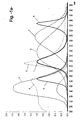
- Figure 1a shows the so-called spectral tristimulus values as a function of wavelength ⁇ . These curves, which represent the amounts of idealised primaries required to match any of the pure spectral colours in the visible range and are related to the colour sensitivity characteristics of the human eye. Curve 1, typically designated as the function x ( ⁇ ), primarily comprises the responsivity of the red sensitive cones of the human retina. The blue sensitive cones' responsivity is, suitably scaled, also included in this first tristimulus curve (see Figure 1b ).
- Curve 2 is, to a good approximation, a summation of the green and red cones' responsivity curves and is designated as the function y ( ⁇ ) and actually corresponds to the overall spectral sensitivity of the eye.
- Curve 3 essentially comprises the blue cones' spectral sensitivity characteristic z ( ⁇ ). It will be clear from these curves that the x ( ⁇ ) curve has a subsidiary maximum in the blue region of the visible spectrum.
- Line 4 represents, following some normalisation, the ratio between z ( ⁇ ) and the root mean squares of x ( ⁇ ) and y ( ⁇ ) and line 5 represents, on the same basis, the ratio between y ( ⁇ ) and the root mean squares of x ( ⁇ ) and z ( ⁇ ).
- the objective in calculating these functions is to find those points within the visible spectrum where the effect of the resultant stimulus of the human visual system is substantially expressed as a change to one of the tristimulus values, with the change to the other two being minimised relative thereto.
- What the two curves show is that, for a maximum change to Z relative to X and Y, stimulation of the human visual system at a wavelength of around 470 nm should be used and that, for maximum change of Y relative to X and Z, stimulation of the human visual system at a wavelength of around 520 nm is most effective.
- X There is no clear choice for X , but a wavelength of around 640 nm is found to achieve good red saturation without too much loss of overall sensitivity.
- the visual or related disability and/or symptom of the subject, experienced under normal illumination can be substantially alleviated.
- a combination of controllable narrow-band light sources located respectively at substantially 470 nm, 520 nm and, say, 640 nm, will readily achieve this goal. All of these wavelengths are substantially achieved with commercially available LED's, the bandwidths of which typically vary from 17 nm to 47 nm.
- Typical examples of such emitted spectra are shown in Figure la as curve 6, for Z, peaking at 470 nm (defined as blue herein), curve 7, for Y, peaking at 524 nm (defined as green herein) and curve 8, for X, peaking at around 640 nm in the red portion of the spectrum.
- the red wavelength is not as critical as the other two, for the reasons stated above.
- a lamp comprising one or more of each type of LED, arranged in a variety of different ways, in which each group of a specific colour is controlled by an adjustable signal, can be used to optimise the illumination for a given subject carrying out a specific task, such as reading or writing. For example, a person who suffers from dyslexia may have a reading difficulty significantly alleviated by the partial or complete exclusion of the red illumination, in effect, by reducing the stimulation of the red sensitive cones.
- Embodiments of the current invention use a multi-colour light emitting diode (LED) array, operated within an optical assembly so that colours can be mixed to create the optimum lighting for any patient.
- An array of different coloured LEDs typically red, green and blue, in accordance with the principles outlined above are operated either individually or together, so that it is possible to select single primary colours or combine the various LEDs to give different hues and illuminance.
- the primary advantage with this type of lighting being that it can be used for both reading and writing.
- a colour selectable lamp allows much greater flexibility and the opportunity to suit the lighting to each user. This could have important applications in the office and school environment where ambient lighting limitations contribute to reading and writing problems for some individuals.
- FIG. 2 this shows diagrammatically how a number of components may be combined in accordance with the principles of the invention to form a colour controllable light source.
- An array of LED's 11 is comprised of red emitters 12, having an emission spectrum peaking at 640 nm, green emitters 13, having an emission spectrum peaking at 524 nm, and blue emitters 14, having an emission spectrum peaking at 470 nm.
- the LED's are distributed in such a manner that the field illuminated by each type at a reading surface 15 is approximately the same.
- a diffuser 16 is placed in the path of the emitted light. This diffuser may take several different forms.
- a lenticular screen or microlens array is found to be effective, as well as other kinds of efficient light scattering media. For example, a material comprising changes of refractive index over short distances can be very effective.
- a divergent lens assembly 18 can be very useful. Although this is shown as a conventional meniscus lens, a compact equivalent, such as a fresnel lens may also be used.
- a control unit 19 receives a number of different inputs, prior to driving each group of LED's via outputs 20 for blue, 21 for green and 22 for red.
- variable resistors 23, 24 and 25 are used to set the light output from the red, green and blue LED's respectively.
- the components identified, thus far, comprise a colour controllable lamp. This can be used by a subject to select a particular combination of red, green and blue spectral components, which is optimal for his or her reading or writing performance.
- a lens 26 forms an image on the receiving surface 27 of a camera 28.
- This may be a CCD or other photo-detector array, behind a colour filter array.
- the video signal from the CCD can be analysed to provide a reading of the level of illumination at surface 15, in addition to its colour mix.
- There will be a specific matrix, which will allow the measure of light passing through each component of the camera's colour filter array to be translated into a red, green and blue LED light combination. Some of this will be contributed by the ambient light impinging on surface 15.
- the output, required from each type of LED, is adjusted by control unit 19, accordingly.
- the resulting system will also be stabilised against other variations, such as changes in the efficiency of the optics or LED's.
- the apparatus of Figure 2 can be very useful as a diagnostic tool, particularly when used in conjunction with a computer, shown as block 29.
- the computer can be used to store the selected tint of the illumination at surface 15, when this has been optimised for the subject.
- FIG. 3 this outlines, in summary form, a methodology in accordance with the invention for establishing the optimal illumination for a specific subject, such as, for example, a person suffering from visual dyslexia.
- the first step in the procedure is to determine the best illumination conditions for a variety of different reading tests. This is done by illuminating the reading material at surface 15 of Figure 2 with one of the spectral components. This is increased in brightness, until the subject is satisfied that the optimal brightness has been found. It may be necessary to pass through the optimum and to reduce the brightness slightly to establish that setting. This step is repeated for each of the spectral components (LED groups), separately. It is quite possible that the optimum level for the red illumination may be at 50% of maximum, for a particular subject, whereas the green and blue spectral components would be quite acceptable at their maximum levels. The particular settings for each spectral component will be highly subject dependent. Step 2 is to record the optimum level for each spectral component, either directly from the controls or transferred automatically to a computer.
- Step 3 of the procedure is to fine tune this mixture by making small adjustments to each spectral component (red, green and blue), in small steps, until an optimum mix is established for the subject.
- the step changes would be made in both directions, decreasing or increasing the particular spectral component, and establishing whether there is an improvement or otherwise in the subject's performance.
- One of the key objectives of this invention is to use the arrangement of Figure 2 as a diagnostic tool, in order to arrive at an optimal formulation for the filters to be provided for the lenses of spectacles or contact lenses to be worn by the subject.
- the colour of the light reaching the subject's eyes is recorded by the system of Figure 2 and stored in computer 29. This record will typically contain information about the settings of the LED sources and, if any, the colour and level of the ambient illumination at the time that the measurements were made. By prior knowledge or use of colour camera 28, any colouration of the reading surface 15 may also be accommodated.
- Curve 41 represents the percentage transmission of a red absorbing (blue tinted) filter as a function T( ⁇ ) of the wavelength ⁇ of the light incident upon it.
- T( ⁇ ) the percentage transmission of a red absorbing (blue tinted) filter as a function of the wavelength ⁇ of the light incident upon it.
- Our interest is in knowing what the response at the retina of each eye will be for each of the cones when the subject views material through this filter. In order to calculate this we must multiply each of the tristimulus curves at every wavelength with the spectral distribution of the light arriving at the retina and integrate this result over the visible spectrum.
- the result will be one of the tristimulus values for the particular tint, as defined by the CIE 1931 chromaticity diagram. It will comprise a number of components, including the following:-
- I( ⁇ ) is the illumination spectrum
- T( ⁇ ) is the filter's transmission spectrum
- R( ⁇ ) is the illuminated substrate's reflectance spectrum
- x ( ⁇ ) is the relevant tristimulus curve, curve 1 in Figure 1a .
- Two further integrals would be calculated for the Y and Z tristimulus values.
- the apparatus of Figure 2 may be used to determine the relative colour response of an individual's eye.
- a surface of known colour reflectance is made to look white by adjusting r, g and b values above.
- CC[f ( ⁇ )] is the colour co-ordinate transformation of a spectrum
- CC p is the perceived white colour response
- E g ( ⁇ ) and E b ( ⁇ ) are the eye responses.
- the embodiment of Figure 2 incorporates a divergent lens to spread the illumination over the desired area, this is not an essential component for the operation of the lamp, as the combination of a diffuser and suitably positioned LED's can be chosen to illuminate any specific area. Whilst the embodiments illustrated herein utilise LED's with relatively narrow-band emission spectra, other devices such as laser sources may be used as alternative illuminants. Furthermore, whereas a camera 28 is employed to analyse the colour of the illumination of surface 15, this could, in practice, be replaced by a series of photodiodes receiving light from this surface through suitable colour filters.
Landscapes
- Health & Medical Sciences (AREA)
- Life Sciences & Earth Sciences (AREA)
- Engineering & Computer Science (AREA)
- Biomedical Technology (AREA)
- General Health & Medical Sciences (AREA)
- Animal Behavior & Ethology (AREA)
- Veterinary Medicine (AREA)
- Public Health (AREA)
- Nuclear Medicine, Radiotherapy & Molecular Imaging (AREA)
- Physics & Mathematics (AREA)
- Psychology (AREA)
- Radiology & Medical Imaging (AREA)
- Developmental Disabilities (AREA)
- Hospice & Palliative Care (AREA)
- Child & Adolescent Psychology (AREA)
- Psychiatry (AREA)
- Social Psychology (AREA)
- Pathology (AREA)
- Biophysics (AREA)
- Ophthalmology & Optometry (AREA)
- Heart & Thoracic Surgery (AREA)
- Medical Informatics (AREA)
- Molecular Biology (AREA)
- Surgery (AREA)
- Radiation-Therapy Devices (AREA)
- Circuit Arrangement For Electric Light Sources In General (AREA)
- Eye Examination Apparatus (AREA)
- Lighting Device Outwards From Vehicle And Optical Signal (AREA)
Abstract
Description
- The current invention is concerned with the provision or filtration of the illumination for a given task, such as reading or writing, and, specifically, with helping to alleviate the symptoms of certain physiological defects, such as dyslexia, or pathological conditions, such as migraine or macular degeneration, which may be suffered by the subject undertaking the task.
- It is known that the response of the visual system is affected by the stimuli, which it receives. The threshold for such stimulation varies between individuals and, under adverse conditions, can significantly reduce performance. When the visual system is over stimulated, it reacts in a number of ways. Amongst a variety of undesirable effects, which can be caused, two examples include a drop in convergence sufficiency and a reduction in the ability to accommodate or fuse images. In addition, visual dyslexia may become apparent and migraines can be caused. Visual dyslexia is a condition of impaired reading and writing ability due to visual perception or visualisation problems. It is apparent therefore that for some it is necessary to modify the visual stimulus by changing the spectral distribution in a specific task e.g. reading and writing in school. In summary, it is well established that the colour of ambient lighting has a major influence on the effects of disorders such as dyslexia, epilepsy and migraine. In the case of dyslexia some sufferers can alleviate their reading problems by covering the page with a transparent coloured overlay in order to block out those wavelengths of light which give rise to an aspect of their problem. These overlays typically remove various amounts of simple primary colours, such as red, green or blue light and whilst they may assist with reading, they are of no value for writing.
- In
US Patent No. 5,855,428 (Wilkins ) apparatus is described in which the spectral distribution of light from a fluorescent lamp to illuminate a surface to support reading material is altered by the interposition of specifically selected broadband filters. By adjustment of the position of the selected filter or filters different colours and saturation thereof can be selected. - In
US Patent Application No 2001/0005319 A1 (Ohishi et al. ) an illumination control system, for general use, is described, in which the coordinates in colour space of the controlled illumination are arranged to follow a predetermined locus of points by mixing specific amounts of light from a plurality of differently coloured light emitting diodes (LED's). This document discloses the preamble ofclaim 1. - It is an object of the current invention to provide optimal illumination for an observer who may be suffering from physiological defects or pathological conditions of his/her visual system in order to alleviate the symptoms thereof.
- It is a further object of the current invention to provide a means for specifying a colour formulation for the lenses of the spectacles to be worn by a patient suffering from one or more of the aforesaid physiological defects or pathological conditions.
- Using a specific controllable light source for a particular task can be preferable to other forms of treatment (e.g. tinted spectacles), as the task lighting can be tailored precisely, for example to take account of the ambient conditions. A specific light is also of particular importance in certain eye conditions such as macular degeneration or cataract as optimum performance is directly related to visual stimulus input, particularly if the person has relatively poor vision. Specific stimulus modification will also be of great use in migraine prevention and treatment with possible uses in attention deficit hyperactivity syndrome and some types of epilepsy. Where it is desirable for the subject to use tinted spectacles, a controllable light source, as described herein, is a useful tool for defining the preferred filter characteristics of the tinted lenses.
- The objects of the current invention are achieved by an apparatus according to
claim 1 and a method according to claims 8 and 10. Preferred embodiments are defined in the dependent claims. - The invention will now be described with reference to
Figures 1a to 4 in which:- -
Figure 1a illustrates the response of the human visual system, as a function of the wavelength of the light incident thereon. Additional curves are provided to aid in the description of the invention. -
Figure 1b provides further curves showing the sensitivity characteristics of the colour receptors or cones at the human retina. -
Figure 2 illustrates, diagrammatically, apparatus constructed in accordance with the invention in order to provide a colour controllable source of illumination, -
Figure 3 shows in flowchart form a preferred method in accordance with the invention for use of the apparatus ofFigure 2 -
Figure 4 shows the transmission spectrum of a typically tinted lens, formulated to reduce the relative stimulus to one type of cone, in accordance with the invention. -
Figure 1a shows the so-called spectral tristimulus values as a function of wavelength λ. These curves, which represent the amounts of idealised primaries required to match any of the pure spectral colours in the visible range and are related to the colour sensitivity characteristics of the human eye.Curve 1, typically designated as the functionx (λ), primarily comprises the responsivity of the red sensitive cones of the human retina. The blue sensitive cones' responsivity is, suitably scaled, also included in this first tristimulus curve (seeFigure 1b ). Curve 2 is, to a good approximation, a summation of the green and red cones' responsivity curves and is designated as the functiony (λ) and actually corresponds to the overall spectral sensitivity of the eye.Curve 3 essentially comprises the blue cones' spectral sensitivity characteristicz (λ). It will be clear from these curves that thex (λ) curve has a subsidiary maximum in the blue region of the visible spectrum. A colour stimulus to the human visual system may be conveniently expressed as three values, the so-called tristimulus values (X, Y and Z), each of which involves an integral over the visible spectrum of the spectral power distribution reaching the retinal cones convolved with the respective tristimulus curve. For example:-
- Two further sets of curves are shown in
Figure 1a . One of these comprisesdashed lines 4 and 5. Line 4 represents, following some normalisation, the ratio betweenz (λ) and the root mean squares ofx (λ) andy (λ) andline 5 represents, on the same basis, the ratio betweeny (λ) and the root mean squares ofx (λ) andz (λ). - The objective in calculating these functions is to find those points within the visible spectrum where the effect of the resultant stimulus of the human visual system is substantially expressed as a change to one of the tristimulus values, with the change to the other two being minimised relative thereto. What the two curves show is that, for a maximum change to Z relative to X and Y, stimulation of the human visual system at a wavelength of around 470 nm should be used and that, for maximum change of Y relative to X and Z, stimulation of the human visual system at a wavelength of around 520 nm is most effective. There is no clear choice for X , but a wavelength of around 640 nm is found to achieve good red saturation without too much loss of overall sensitivity.
- It is an objective of this invention to provide a means for controlling the colour stimulation of the human visual system, so that an optimum ratio of X, Y and Z values can be established. When this is achieved, the visual or related disability and/or symptom of the subject, experienced under normal illumination, can be substantially alleviated. It will be clear that a combination of controllable narrow-band light sources, located respectively at substantially 470 nm, 520 nm and, say, 640 nm, will readily achieve this goal. All of these wavelengths are substantially achieved with commercially available LED's, the bandwidths of which typically vary from 17 nm to 47 nm. Typical examples of such emitted spectra are shown in Figure la as curve 6, for Z, peaking at 470 nm (defined as blue herein), curve 7, for Y, peaking at 524 nm (defined as green herein) and curve 8, for X, peaking at around 640 nm in the red portion of the spectrum. The red wavelength is not as critical as the other two, for the reasons stated above.
- By combining the light from the three different types of LED, as specified above, a wide range of tints can be achieved. A lamp comprising one or more of each type of LED, arranged in a variety of different ways, in which each group of a specific colour is controlled by an adjustable signal, can be used to optimise the illumination for a given subject carrying out a specific task, such as reading or writing. For example, a person who suffers from dyslexia may have a reading difficulty significantly alleviated by the partial or complete exclusion of the red illumination, in effect, by reducing the stimulation of the red sensitive cones.
- Embodiments of the current invention use a multi-colour light emitting diode (LED) array, operated within an optical assembly so that colours can be mixed to create the optimum lighting for any patient. An array of different coloured LEDs, typically red, green and blue, in accordance with the principles outlined above are operated either individually or together, so that it is possible to select single primary colours or combine the various LEDs to give different hues and illuminance. The primary advantage with this type of lighting being that it can be used for both reading and writing.
- A colour selectable lamp allows much greater flexibility and the opportunity to suit the lighting to each user. This could have important applications in the office and school environment where ambient lighting limitations contribute to reading and writing problems for some individuals.
- Turning to
Figure 2 , this shows diagrammatically how a number of components may be combined in accordance with the principles of the invention to form a colour controllable light source. - An array of LED's 11 is comprised of
red emitters 12, having an emission spectrum peaking at 640 nm,green emitters 13, having an emission spectrum peaking at 524 nm, andblue emitters 14, having an emission spectrum peaking at 470 nm. The LED's are distributed in such a manner that the field illuminated by each type at areading surface 15 is approximately the same. In order to ensure that there are no substantial differences in the mix of colours at any given point on the reading surface, adiffuser 16 is placed in the path of the emitted light. This diffuser may take several different forms. A lenticular screen or microlens array is found to be effective, as well as other kinds of efficient light scattering media. For example, a material comprising changes of refractive index over short distances can be very effective. - The effect of distributing the individual LED's in an even manner, together with the action of the
diffuser 16, is to provide a very even mix of light at the readingsurface 15. In order to extend the effective area of illumination, adivergent lens assembly 18 can be very useful. Although this is shown as a conventional meniscus lens, a compact equivalent, such as a fresnel lens may also be used. - A
control unit 19 receives a number of different inputs, prior to driving each group of LED's viaoutputs 20 for blue, 21 for green and 22 for red. At its simplest level,variable resistors - In practice, a more sophisticated version of such a lamp would adapt the light output demanded from the LED array to take account of the ambient conditions. In
Figure 2 alens 26 forms an image on the receivingsurface 27 of acamera 28. This may be a CCD or other photo-detector array, behind a colour filter array. Using known principles, the video signal from the CCD can be analysed to provide a reading of the level of illumination atsurface 15, in addition to its colour mix. There will be a specific matrix, which will allow the measure of light passing through each component of the camera's colour filter array to be translated into a red, green and blue LED light combination. Some of this will be contributed by the ambient light impinging onsurface 15. The output, required from each type of LED, is adjusted bycontrol unit 19, accordingly. As a consequence of the use ofcamera 28 to monitor the illumination ofsurface 15 the resulting system will also be stabilised against other variations, such as changes in the efficiency of the optics or LED's. - The apparatus of
Figure 2 can be very useful as a diagnostic tool, particularly when used in conjunction with a computer, shown asblock 29. Inter alia, the computer can be used to store the selected tint of the illumination atsurface 15, when this has been optimised for the subject. - Turning to
Figure 3 , this outlines, in summary form, a methodology in accordance with the invention for establishing the optimal illumination for a specific subject, such as, for example, a person suffering from visual dyslexia. - The first step in the procedure is to determine the best illumination conditions for a variety of different reading tests. This is done by illuminating the reading material at
surface 15 ofFigure 2 with one of the spectral components. This is increased in brightness, until the subject is satisfied that the optimal brightness has been found. It may be necessary to pass through the optimum and to reduce the brightness slightly to establish that setting. This step is repeated for each of the spectral components (LED groups), separately. It is quite possible that the optimum level for the red illumination may be at 50% of maximum, for a particular subject, whereas the green and blue spectral components would be quite acceptable at their maximum levels. The particular settings for each spectral component will be highly subject dependent. Step 2 is to record the optimum level for each spectral component, either directly from the controls or transferred automatically to a computer. - Once the individual optima have been established, the recorded levels of each spectral component are combined in
Step 3 of the procedure. Step 4 is to fine tune this mixture by making small adjustments to each spectral component (red, green and blue), in small steps, until an optimum mix is established for the subject. The step changes would be made in both directions, decreasing or increasing the particular spectral component, and establishing whether there is an improvement or otherwise in the subject's performance. By iteration ofSteps 3 and 4, the best combination is found. - One of the key objectives of this invention is to use the arrangement of
Figure 2 as a diagnostic tool, in order to arrive at an optimal formulation for the filters to be provided for the lenses of spectacles or contact lenses to be worn by the subject. The colour of the light reaching the subject's eyes is recorded by the system ofFigure 2 and stored incomputer 29. This record will typically contain information about the settings of the LED sources and, if any, the colour and level of the ambient illumination at the time that the measurements were made. By prior knowledge or use ofcolour camera 28, any colouration of the readingsurface 15 may also be accommodated. - In practice there will be a finite selection of filter formulations available. A typical filter characteristic is shown in
Figure 4 . Curve 41 represents the percentage transmission of a red absorbing (blue tinted) filter as a function T(λ) of the wavelength λ of the light incident upon it. Our interest is in knowing what the response at the retina of each eye will be for each of the cones when the subject views material through this filter. In order to calculate this we must multiply each of the tristimulus curves at every wavelength with the spectral distribution of the light arriving at the retina and integrate this result over the visible spectrum. The result will be one of the tristimulus values for the particular tint, as defined by the CIE 1931 chromaticity diagram. It will comprise a number of components, including the following:- - 1) the spectrum of the illumination which the subject will use when reading or writing (This could be daylight or light from a tungsten or fluorescent lamp and each will have a different spectrum),
- 2) the background reflectance spectrum of the material being read and
- 3) the relevant tristimulus curve.
- For the response corresponding to each of the tristimulus values the integral required will be of the form

- Where I(λ) is the illumination spectrum, T(λ) is the filter's transmission spectrum, R(λ) is the illuminated substrate's reflectance spectrum and x (λ) is the relevant tristimulus curve,
curve 1 inFigure 1a . Two further integrals would be calculated for the Y and Z tristimulus values. - It will be clear to those versed in the art that the same tristimulus values can be achieved with a different illumination spectrum and, in principle, without the use of the intervening transmission filter. Indeed, where the illumination spectrum is comprised of the combination of the three spectral compoments provided by the red, green and blue LED's of
Figure 2 , this spectrum will have three well-defined peaks. As already explained, by reference toFigure 1a andFigure 1b , each of these peaks will have a particularly significant influence on only one of the tristimulus values. - It is a further objective of this invention to simulate the effect of any particular filter by providing illumination which simulates the effect on the visual system that would result from the use of that filter under the expected lighting conditions. Thus the LED outputs, with the reflectance characteristics of the reading
surface 15 inFigure 2 being taken into account, must be adjusted to simulate that part of the function under the integral above represented by I(λ)T(λ)R(λ). In effect, I(λ)T(λ) will be replaced by the following expression:-
where r, g and b represent the components of each of the spectral components and R(λ), G(λ) and B(λ) are the respective spectral power distributions of these, as shown inFigure 1a as curves 8, 7 and 6 respectively. - For every choice of filter characteristic available there will be values of r, g and b which will simulate the effect for the subject under a particular selection of lighting. Having established an optimal tristimulus value for the subject by using the procedure of
Figure 3 , a best choice of tint may be selected or formulated. A database of all standard filters may be held oncomputer 29, in order to provide a convenient method for prescribing an available choice of filter. The precise effect of that filter being available for the subject to experience by simulation using the apparatus ofFigure 2 - It follows from this that the apparatus of
Figure 2 may be used to determine the relative colour response of an individual's eye. In this case a surface of known colour reflectance is made to look white by adjusting r, g and b values above. The expression describing this is:
where CC[f (λ)] is the colour co-ordinate transformation of a spectrum, CCp is the perceived white colour response and Er(λ), Eg(λ) and Eb(λ) are the eye responses. For a known surface and instrument settings and a normal eye response then the perceived white colour will correspond with the actual colour co-ordinates of white with CCp = [0.33,0.33,0.33]. - For an eye with a different colour response CCp will be at a different position in colour space and the vector between this position and nominal white will be a measurement of relative colour response of the eye.
- By further reference to
Figure 1a it also follows that, in order to reduce the X tristimulus value to a minimum, a light source with its energy concentrated at around 505 nm is required. Such a facility may prove particularly useful in circumstances where the function of the lamp is a diagnostic one and a complete absence of the X stimulus is desired. - Although the embodiment of
Figure 2 incorporates a divergent lens to spread the illumination over the desired area, this is not an essential component for the operation of the lamp, as the combination of a diffuser and suitably positioned LED's can be chosen to illuminate any specific area. Whilst the embodiments illustrated herein utilise LED's with relatively narrow-band emission spectra, other devices such as laser sources may be used as alternative illuminants. Furthermore, whereas acamera 28 is employed to analyse the colour of the illumination ofsurface 15, this could, in practice, be replaced by a series of photodiodes receiving light from this surface through suitable colour filters.
Claims (13)
- Apparatus for the quantitative diagnosis and/or alleviation of the symptoms of a plurality of visually induced physiological defects and/or pathological conditions suffered by an observer comprising- a plurality of controllable narrow band coloured light sources (12, 13, 14), the light sources arranged to provide illumination of a surface (15) for viewing by said observer, said surface suitable for reading or writing texts, and- each of the light sources (12, 13, 14) emitting a respective spectral component of the visible spectrum contributing predominantly to one of the tristimulus values X, Y, Z of the light entering an eye of the observer, whereby light sources predominantly contributing to each of the three tristimulus values X, Y, and Z are present, and- control means (19) for selecting a weighted mixture of said spectral components wherein said mixture is an additive combination of said spectral components emitted by said light sources, and said control means provides the means (23, 24, 25) for varying the amount of illumination from each of said light sources (12, 13, 14)characterised in that
the spectral component predominantly contributing to the Y tristimulus value has its peak at a wavelength which is located between 520 nm and 530 nm thereby minimizing its contribution to the X and Z tristimulus values. - Apparatus as claimed in Claim 1 in which the spectral component predominantly contributing to the Z tristimulus value has its peak at a dominant wavelength located between 465 nm and 475 nm.
- Apparatus as claimed in Claim 1 in which the spectral component predominantly contributing to the X tristimulus value has its peak at a wavelength in the range 610 nm and 650 nm.
- Apparatus as claimed in Claim 1 in which each of said light sources comprises at least one respective light emitting diode arranged to provide one of said spectral components.
- Apparatus as claimed in Claim 1 in which a spectral component has a spectral power distribution having a ban width at half height which does not exceed 50 nm.
- Apparatus as claimed in Claim 1 in which the illumination from each of the light sources is diffused prior to impinging on the surface so that the relative intensity of the light impinging at two points spaced on said surface is substantially the same for each of said spectral components.
- Apparatus as claimed in Claim 1 further comprising means for computing the combined effect of at least two of the active illumination spectra, the ambient illumination spectrum, the reflectance spectrum of the target or an illuminated surface, the transmission spectrum of at least one filter and the transmission spectrum of a surface coating over the visible spectrum, so that in use, the subject's retinal response may be predicted and the settings of the active light source and/or the formulation of a filter to be used by the subject may be optimised.
- A method for finding the optimal illumination for a subject, characterised by implementing the successive steps of -a) arranging the apparatus in accordance with Claim 1 to provide a plurality of spectral components.b) assessing the subject's performance with a series of targets under different levels of each of said plurality of spectral components, either individually or combined in pre-determined ratios thereof.c) recording the optimum level of each of said spectral componentsd) combining the levels of each respective spectral component as recorded in step (c) to provide a resultant additive mix of said spectral components.
- The method of Claim 8 including the further step of applying variations to the level of each spectral component in small steps whilst said spectral components are combined in order to establish the mix of said spectral components which substantially optimises the subject's performance.
- A method for the simulation of the use of a particular filter under expected lighting conditions which comprises the steps of:-(a) defining the tristimulus values of the tint which would be observed under the expected lighting conditions by an observer when said filter is used in transmission for viewing a reading surface(b) providing the apparatus of Claim 1(c) selecting the level of illumination provided by each light source of said apparatus(d) illuminating the reading surface for viewing by the observer with said apparatus so that, in use, the defined tristimulus values are observed by the observer
- The method of claim 10 further comprising the step of simulating a range of pre-formulated filters and lighting conditions, whereby the observer can select one or more filters for use under said conditions.
- The method of claim 10 or claim 11 which includes the further step of formulating and/or selecting the filter to optimise the observer's performance.
- A method as claimed in any one of claims 10 to 12 applied to the formulation of filters and/or anti-reflection coatings for spectacles, contact lenses, coloured overlays or any other tinted material a purpose of which is to alleviate problems caused by colour related disorders of the human visual system.
Applications Claiming Priority (5)
| Application Number | Priority Date | Filing Date | Title |
|---|---|---|---|
| GB0031384 | 2000-12-21 | ||
| GB0031384A GB0031384D0 (en) | 2000-12-21 | 2000-12-21 | A means to optimise the illumination for sufferers of disorder such as dyslexiamigraine and epilepsy using a task light with controllable colour |
| GB0128705A GB0128705D0 (en) | 2001-11-30 | 2001-11-30 | Apparatus and method for alleviation of symptons by application of tinted light |
| GB0128705 | 2001-11-30 | ||
| PCT/GB2001/005544 WO2002049721A1 (en) | 2000-12-21 | 2001-12-17 | Apparatus and method for alleviation of symptoms by application of tinted light |
Publications (2)
| Publication Number | Publication Date |
|---|---|
| EP1345656A1 EP1345656A1 (en) | 2003-09-24 |
| EP1345656B1 true EP1345656B1 (en) | 2008-07-23 |
Family
ID=26245476
Family Applications (1)
| Application Number | Title | Priority Date | Filing Date |
|---|---|---|---|
| EP01271246A Expired - Lifetime EP1345656B1 (en) | 2000-12-21 | 2001-12-17 | Apparatus for alleviation of symptoms by application of tinted light |
Country Status (7)
| Country | Link |
|---|---|
| US (2) | US20030223036A1 (en) |
| EP (1) | EP1345656B1 (en) |
| JP (1) | JP2004524067A (en) |
| AT (1) | ATE401932T1 (en) |
| AU (1) | AU2002222220A1 (en) |
| DE (1) | DE60135018D1 (en) |
| WO (1) | WO2002049721A1 (en) |
Cited By (1)
| Publication number | Priority date | Publication date | Assignee | Title |
|---|---|---|---|---|
| US11826100B2 (en) | 2018-02-13 | 2023-11-28 | Essilor International | Wearable binocular optoelectronic device for measuring light sensitivity threshold of a user |
Families Citing this family (33)
| Publication number | Priority date | Publication date | Assignee | Title |
|---|---|---|---|---|
| US6200134B1 (en) | 1998-01-20 | 2001-03-13 | Kerr Corporation | Apparatus and method for curing materials with radiation |
| JP2004524067A (en) | 2000-12-21 | 2004-08-12 | ディバース・テクノロジーズ・アンド・システムズ・リミテッド | Apparatus and method for alleviating symptoms by irradiation of colored light |
| JP2005534201A (en) | 2002-07-25 | 2005-11-10 | ジョナサン エス. ダーム、 | Method and apparatus for using light emitting diodes for curing |
| DE10301867A1 (en) * | 2003-01-17 | 2004-07-29 | Günther, Andreas | Color generation device for generating colors or color mixtures in front of the eyes of a wearer, comprises a ski goggles or spectacles type arrangement with transparent color light screens arranged in front of each eye |
| GB0311122D0 (en) * | 2003-05-15 | 2003-06-18 | Orthoscopics Ltd | Apparatus for the concurrent alleviation of visually induced symptoms and assessment of performance and associated methods |
| US8064772B2 (en) | 2005-02-07 | 2011-11-22 | Panasonic Corporation | Optical space transmitter and optical space transmission method for wavelength-multiplexed light |
| JP2007052954A (en) * | 2005-08-16 | 2007-03-01 | Seiwa Electric Mfg Co Ltd | Lighting system |
| DE102006010105A1 (en) * | 2006-02-28 | 2007-08-30 | Carl Zeiss Meditec Ag | Ophthalmologic device for observation and or documentation of eye, has homogeneous lighting, and lighting equipment consists of light source, homogenization unit and projection device |
| DE102007004364A1 (en) * | 2007-01-29 | 2008-07-31 | Carl Zeiss Meditec Ag | Device for manufacturing optical element for correction of age-related macular degeneration of retina of eye, has detection unit for identification of functioning macular regions of retina of eye |
| EP2164568B1 (en) * | 2007-05-31 | 2016-02-24 | Koninklijke Philips N.V. | System for providing illumination and physiological stimuli |
| US9072572B2 (en) | 2009-04-02 | 2015-07-07 | Kerr Corporation | Dental light device |
| US9066777B2 (en) | 2009-04-02 | 2015-06-30 | Kerr Corporation | Curing light device |
| KR100998473B1 (en) * | 2010-05-20 | 2010-12-06 | 전자부품연구원 | A sterilizer with ultra violet light emitting diode |
| US10359552B2 (en) | 2011-01-17 | 2019-07-23 | University Of Utah Research Foundation | Methods, systems, and apparatus for reducing the frequency and/or severity of photophobic responses or for modulating circadian cycles |
| ES2962140T3 (en) | 2011-01-17 | 2024-03-15 | Univ Utah Res Found | Devices and methods to reduce the frequency or severity of photophobic responses or modulate circadian cycles |
| US9764157B2 (en) | 2011-01-17 | 2017-09-19 | University Of Utah Research Foundation | Methods, systems, and apparatus for reducing the frequency and/or severity of photophobic responses or for modulating circadian cycles |
| GB201106882D0 (en) * | 2011-04-26 | 2011-06-01 | Univ Leicester | Apparatus and method |
| US9820643B2 (en) | 2013-08-13 | 2017-11-21 | Jasper Ridge Inc. | Illumination evaluation or recommendation using visual function |
| WO2015023676A1 (en) * | 2013-08-13 | 2015-02-19 | Jasper Ridge Inc. | Illumination evaluation or recommendation using visual function |
| US10234608B2 (en) | 2013-11-15 | 2019-03-19 | University Of Utah Research Foundation | Nanoparticle light filtering method and apparatus |
| US10281627B2 (en) | 2013-11-15 | 2019-05-07 | University Of Utah Research Foundation | Nanoparticle light filtering method and apparatus |
| US9378563B2 (en) | 2014-02-18 | 2016-06-28 | Herbert A. Wertheim | Method for simulating the effect of viewing an image through a colored filter or ophthalmic spectacle lens |
| US10806890B2 (en) | 2015-06-19 | 2020-10-20 | Beth Israel Deaconess Medical Center, Inc. | Method and apparatus for managing photophobia and migraine photophobia |
| GB201519117D0 (en) * | 2015-10-29 | 2015-12-16 | Univ Essex Entpr Ltd | Visual stress assessment device |
| WO2018067741A1 (en) * | 2016-10-07 | 2018-04-12 | Enchroma, Inc. | Lighting system for simulating conditions of color deficient vision and demonstrating effectiveness of colorblindness compensating eyewear |
| IT201600129679A1 (en) * | 2016-12-21 | 2018-06-21 | Probiomedica S R L | Ingestible capsule for the phototherapeutic treatment of infections |
| JP2019024952A (en) * | 2017-07-28 | 2019-02-21 | パナソニックIpマネジメント株式会社 | Bath light device |
| EP3495875A1 (en) * | 2017-12-06 | 2019-06-12 | Essilor International | Method and system for selecting a color filter, optical article comprising such a color filter |
| JPWO2019124449A1 (en) * | 2017-12-22 | 2020-08-20 | 株式会社ビジュアル・テクノロジー研究所 | Visual function inspection and optical characteristic calculation system |
| KR102108634B1 (en) * | 2018-08-24 | 2020-05-28 | 송인실 | Apparatus for skin treatment |
| EP3629080A1 (en) * | 2018-09-25 | 2020-04-01 | Essilor International (Compagnie Generale D'optique) | Ophthalmic device with a blinking illuminating element for reducing dyslexia effects |
| JP7184414B1 (en) | 2022-08-08 | 2022-12-06 | 株式会社薫化舎 | Characteristics information collection method and characteristics information collection device |
| JP7220000B1 (en) | 2022-08-08 | 2023-02-09 | 株式会社薫化舎 | Characteristics information collection method and characteristics information collection device |
Citations (1)
| Publication number | Priority date | Publication date | Assignee | Title |
|---|---|---|---|---|
| EP1114608A1 (en) * | 2000-01-07 | 2001-07-11 | Nidek Co., Ltd. | Eye observation apparatus having a plurality of individually controlled LEDs for colour corrected illumination |
Family Cites Families (19)
| Publication number | Priority date | Publication date | Assignee | Title |
|---|---|---|---|---|
| US5319A (en) | 1847-10-02 | pkoto-tltho | ||
| NL8200517A (en) * | 1982-02-11 | 1983-09-01 | Tno | ADJUSTING CIRCUIT FOR LIGHT EMITTING DIODE WITH TEMPERATURE COMPENSATION. |
| US4961640A (en) * | 1982-08-20 | 1990-10-09 | Irlen Helen L | Method and apparatus of treatment of symptoms of the Irlen syndrom |
| US4648051A (en) * | 1984-10-15 | 1987-03-03 | The Board Of Trustees Of The Leland Stanford Junior University | Color imaging process |
| DK0540539T3 (en) * | 1990-07-25 | 1997-07-14 | Medical Res Council | Apparatus and method for obtaining a desired color. |
| US6459425B1 (en) * | 1997-08-25 | 2002-10-01 | Richard A. Holub | System for automatic color calibration |
| JPH09329497A (en) * | 1996-04-11 | 1997-12-22 | Olympus Optical Co Ltd | Colorimeter and colorimetery |
| GB9608476D0 (en) | 1996-04-25 | 1996-07-03 | Medical Res Council | Apparatus for obtaining a desired tint |
| US7014336B1 (en) * | 1999-11-18 | 2006-03-21 | Color Kinetics Incorporated | Systems and methods for generating and modulating illumination conditions |
| US20040052076A1 (en) * | 1997-08-26 | 2004-03-18 | Mueller George G. | Controlled lighting methods and apparatus |
| US5929999A (en) * | 1998-09-01 | 1999-07-27 | Hewlett-Packard Company | Light source for tristimulus colorimetry |
| DE19901669A1 (en) * | 1999-01-18 | 2000-08-17 | Jb Lighting Lichtanlagentechni | Spotlight, especially for disco and office lighting, has differently colored LEDs uniformly distributed next to each other on base plate, with individual, group or color group intensity control |
| CN1361674A (en) * | 1999-07-15 | 2002-07-31 | 汀特威逊有限公司 | Method of testing and corresponding vision aid |
| DE19942177A1 (en) * | 1999-09-03 | 2001-03-22 | Osram Opto Semiconductors Gmbh | Lamp with electrically-controlled light source provided by semiconductor element emitting visible electromagnetic radiation controlled for providing variable light intensity and/or color spectrum |
| JP4495814B2 (en) * | 1999-12-28 | 2010-07-07 | アビックス株式会社 | Dimmable LED lighting fixture |
| US6870523B1 (en) * | 2000-06-07 | 2005-03-22 | Genoa Color Technologies | Device, system and method for electronic true color display |
| JP2004524067A (en) | 2000-12-21 | 2004-08-12 | ディバース・テクノロジーズ・アンド・システムズ・リミテッド | Apparatus and method for alleviating symptoms by irradiation of colored light |
| US6851809B1 (en) * | 2001-10-22 | 2005-02-08 | Massachusetts Institute Of Technology | Color vision deficiency screening test resistant to display calibration errors |
| US6851807B2 (en) * | 2002-09-25 | 2005-02-08 | Kd Holdings Group, Inc. | Vision therapy system and method |
-
2001
- 2001-12-17 JP JP2002551054A patent/JP2004524067A/en active Pending
- 2001-12-17 EP EP01271246A patent/EP1345656B1/en not_active Expired - Lifetime
- 2001-12-17 AT AT01271246T patent/ATE401932T1/en not_active IP Right Cessation
- 2001-12-17 WO PCT/GB2001/005544 patent/WO2002049721A1/en active IP Right Grant
- 2001-12-17 DE DE60135018T patent/DE60135018D1/en not_active Expired - Lifetime
- 2001-12-17 AU AU2002222220A patent/AU2002222220A1/en not_active Abandoned
-
2003
- 2003-06-19 US US10/464,491 patent/US20030223036A1/en not_active Abandoned
-
2007
- 2007-02-05 US US11/702,179 patent/US7380940B2/en not_active Expired - Fee Related
Patent Citations (1)
| Publication number | Priority date | Publication date | Assignee | Title |
|---|---|---|---|---|
| EP1114608A1 (en) * | 2000-01-07 | 2001-07-11 | Nidek Co., Ltd. | Eye observation apparatus having a plurality of individually controlled LEDs for colour corrected illumination |
Cited By (1)
| Publication number | Priority date | Publication date | Assignee | Title |
|---|---|---|---|---|
| US11826100B2 (en) | 2018-02-13 | 2023-11-28 | Essilor International | Wearable binocular optoelectronic device for measuring light sensitivity threshold of a user |
Also Published As
| Publication number | Publication date |
|---|---|
| EP1345656A1 (en) | 2003-09-24 |
| US20030223036A1 (en) | 2003-12-04 |
| DE60135018D1 (en) | 2008-09-04 |
| WO2002049721A1 (en) | 2002-06-27 |
| ATE401932T1 (en) | 2008-08-15 |
| US20070139611A1 (en) | 2007-06-21 |
| US7380940B2 (en) | 2008-06-03 |
| AU2002222220A1 (en) | 2002-07-01 |
| JP2004524067A (en) | 2004-08-12 |
| WO2002049721A9 (en) | 2002-08-15 |
Similar Documents
| Publication | Publication Date | Title |
|---|---|---|
| EP1345656B1 (en) | Apparatus for alleviation of symptoms by application of tinted light | |
| EP3523569B1 (en) | Lighting system for simulating conditions of color deficient vision and demonstrating effectiveness of colorblindness compensating eyewear | |
| US20060262272A1 (en) | Apparatus and method for application of tinted light and concurrent assessment of performance | |
| JP7343502B2 (en) | Method and system for selecting color filters | |
| Eichengreen | Unique hue loci: induced shifts with complementary surrounds | |
| US10499805B2 (en) | Visual stress assessment device | |
| McCann et al. | Temporary Tritanopia: Effects of cataract surgery on color | |
| Wei | Effects of spectral modification on perceived brightness and color discrimination | |
| Ikeda et al. | Desaturation of color by environment light in cataract eyes | |
| Wilkerson | Reallocation of narrow bands of spectral energy: The effect on brightness perception and color preference | |
| Wilkins et al. | Coloured filters: clinical tools | |
| Bao et al. | Light Sources with a Larger Gamut Area Can Enhance Color Preference under a Lower Light Level | |
| van Creveld | An investigation into the relationship between luminance and brightness of strongly chromatic light sources | |
| van der Westhuyzen | The Role of the Reference Source in Improving the Cie Colour-Rendering Index for Visual Perception Optimisation | |
| Branch | AFRL-RH-BR-TR-2009-0051 | |
| Davson et al. | Some general aspects of vision | |
| Petrulis et al. | Metameric Light Sources: A Recent Paradigm for Functional Lighting | |
| Vik | COLORIMETRY | |
| Akita et al. | Differences of unique‐yellow loci between individuals | |
| Bodrogi et al. | The Human Visual System and Its Modeling for Lighting Engineering | |
| Songden et al. | On The Models of Colour Vision. | |
| Eisner | Retinal chromaticity co-ordinates and color appearance | |
| Ciardullo et al. | Magnitude estimations of brightness for lights of different wavelengths | |
| Hertog | THE CHROMATICITY OF WHITE LIGHT | |
| Zak et al. | Luminescence spectrum and visual efficiency of color video display terminals |
Legal Events
| Date | Code | Title | Description |
|---|---|---|---|
| PUAI | Public reference made under article 153(3) epc to a published international application that has entered the european phase |
Free format text: ORIGINAL CODE: 0009012 |
|
| 17P | Request for examination filed |
Effective date: 20030718 |
|
| AK | Designated contracting states |
Kind code of ref document: A1 Designated state(s): AT BE CH CY DE DK ES FI FR GB GR IE IT LI LU MC NL PT SE TR |
|
| AX | Request for extension of the european patent |
Extension state: AL LT LV MK RO SI |
|
| GRAP | Despatch of communication of intention to grant a patent |
Free format text: ORIGINAL CODE: EPIDOSNIGR1 |
|
| RTI1 | Title (correction) |
Free format text: APPARATUS FOR ALLEVIATION OF SYMPTOMS BY APPLICATION OF TINTED LIGHT |
|
| GRAS | Grant fee paid |
Free format text: ORIGINAL CODE: EPIDOSNIGR3 |
|
| RAP1 | Party data changed (applicant data changed or rights of an application transferred) |
Owner name: ORTHOSCOPICS LIMITED |
|
| GRAA | (expected) grant |
Free format text: ORIGINAL CODE: 0009210 |
|
| AK | Designated contracting states |
Kind code of ref document: B1 Designated state(s): AT BE CH CY DE DK ES FI FR GB GR IE IT LI LU MC NL PT SE TR |
|
| REG | Reference to a national code |
Ref country code: GB Ref legal event code: FG4D |
|
| REG | Reference to a national code |
Ref country code: CH Ref legal event code: EP |
|
| REG | Reference to a national code |
Ref country code: IE Ref legal event code: FG4D |
|
| REF | Corresponds to: |
Ref document number: 60135018 Country of ref document: DE Date of ref document: 20080904 Kind code of ref document: P |
|
| NLV1 | Nl: lapsed or annulled due to failure to fulfill the requirements of art. 29p and 29m of the patents act | ||
| PG25 | Lapsed in a contracting state [announced via postgrant information from national office to epo] |
Ref country code: ES Free format text: LAPSE BECAUSE OF FAILURE TO SUBMIT A TRANSLATION OF THE DESCRIPTION OR TO PAY THE FEE WITHIN THE PRESCRIBED TIME-LIMIT Effective date: 20081103 Ref country code: NL Free format text: LAPSE BECAUSE OF FAILURE TO SUBMIT A TRANSLATION OF THE DESCRIPTION OR TO PAY THE FEE WITHIN THE PRESCRIBED TIME-LIMIT Effective date: 20080723 Ref country code: PT Free format text: LAPSE BECAUSE OF FAILURE TO SUBMIT A TRANSLATION OF THE DESCRIPTION OR TO PAY THE FEE WITHIN THE PRESCRIBED TIME-LIMIT Effective date: 20081223 |
|
| PG25 | Lapsed in a contracting state [announced via postgrant information from national office to epo] |
Ref country code: AT Free format text: LAPSE BECAUSE OF FAILURE TO SUBMIT A TRANSLATION OF THE DESCRIPTION OR TO PAY THE FEE WITHIN THE PRESCRIBED TIME-LIMIT Effective date: 20080723 Ref country code: FI Free format text: LAPSE BECAUSE OF FAILURE TO SUBMIT A TRANSLATION OF THE DESCRIPTION OR TO PAY THE FEE WITHIN THE PRESCRIBED TIME-LIMIT Effective date: 20080723 |
|
| PG25 | Lapsed in a contracting state [announced via postgrant information from national office to epo] |
Ref country code: BE Free format text: LAPSE BECAUSE OF FAILURE TO SUBMIT A TRANSLATION OF THE DESCRIPTION OR TO PAY THE FEE WITHIN THE PRESCRIBED TIME-LIMIT Effective date: 20080723 |
|
| PG25 | Lapsed in a contracting state [announced via postgrant information from national office to epo] |
Ref country code: DK Free format text: LAPSE BECAUSE OF FAILURE TO SUBMIT A TRANSLATION OF THE DESCRIPTION OR TO PAY THE FEE WITHIN THE PRESCRIBED TIME-LIMIT Effective date: 20080723 |
|
| PLBE | No opposition filed within time limit |
Free format text: ORIGINAL CODE: 0009261 |
|
| STAA | Information on the status of an ep patent application or granted ep patent |
Free format text: STATUS: NO OPPOSITION FILED WITHIN TIME LIMIT |
|
| 26N | No opposition filed |
Effective date: 20090424 |
|
| PG25 | Lapsed in a contracting state [announced via postgrant information from national office to epo] |
Ref country code: MC Free format text: LAPSE BECAUSE OF NON-PAYMENT OF DUE FEES Effective date: 20081231 |
|
| REG | Reference to a national code |
Ref country code: CH Ref legal event code: PL |
|
| PG25 | Lapsed in a contracting state [announced via postgrant information from national office to epo] |
Ref country code: IT Free format text: LAPSE BECAUSE OF FAILURE TO SUBMIT A TRANSLATION OF THE DESCRIPTION OR TO PAY THE FEE WITHIN THE PRESCRIBED TIME-LIMIT Effective date: 20080723 |
|
| PG25 | Lapsed in a contracting state [announced via postgrant information from national office to epo] |
Ref country code: CH Free format text: LAPSE BECAUSE OF NON-PAYMENT OF DUE FEES Effective date: 20081231 Ref country code: LI Free format text: LAPSE BECAUSE OF NON-PAYMENT OF DUE FEES Effective date: 20081231 |
|
| PG25 | Lapsed in a contracting state [announced via postgrant information from national office to epo] |
Ref country code: SE Free format text: LAPSE BECAUSE OF FAILURE TO SUBMIT A TRANSLATION OF THE DESCRIPTION OR TO PAY THE FEE WITHIN THE PRESCRIBED TIME-LIMIT Effective date: 20081023 |
|
| PGFP | Annual fee paid to national office [announced via postgrant information from national office to epo] |
Ref country code: IE Payment date: 20091028 Year of fee payment: 9 |
|
| PG25 | Lapsed in a contracting state [announced via postgrant information from national office to epo] |
Ref country code: LU Free format text: LAPSE BECAUSE OF NON-PAYMENT OF DUE FEES Effective date: 20081217 Ref country code: CY Free format text: LAPSE BECAUSE OF FAILURE TO SUBMIT A TRANSLATION OF THE DESCRIPTION OR TO PAY THE FEE WITHIN THE PRESCRIBED TIME-LIMIT Effective date: 20080723 |
|
| PG25 | Lapsed in a contracting state [announced via postgrant information from national office to epo] |
Ref country code: TR Free format text: LAPSE BECAUSE OF FAILURE TO SUBMIT A TRANSLATION OF THE DESCRIPTION OR TO PAY THE FEE WITHIN THE PRESCRIBED TIME-LIMIT Effective date: 20080723 |
|
| PG25 | Lapsed in a contracting state [announced via postgrant information from national office to epo] |
Ref country code: GR Free format text: LAPSE BECAUSE OF FAILURE TO SUBMIT A TRANSLATION OF THE DESCRIPTION OR TO PAY THE FEE WITHIN THE PRESCRIBED TIME-LIMIT Effective date: 20081024 |
|
| REG | Reference to a national code |
Ref country code: IE Ref legal event code: MM4A |
|
| PGFP | Annual fee paid to national office [announced via postgrant information from national office to epo] |
Ref country code: DE Payment date: 20110519 Year of fee payment: 10 |
|
| PG25 | Lapsed in a contracting state [announced via postgrant information from national office to epo] |
Ref country code: IE Free format text: LAPSE BECAUSE OF NON-PAYMENT OF DUE FEES Effective date: 20101217 |
|
| PGFP | Annual fee paid to national office [announced via postgrant information from national office to epo] |
Ref country code: FR Payment date: 20111220 Year of fee payment: 11 |
|
| REG | Reference to a national code |
Ref country code: FR Ref legal event code: ST Effective date: 20130830 |
|
| REG | Reference to a national code |
Ref country code: DE Ref legal event code: R119 Ref document number: 60135018 Country of ref document: DE Effective date: 20130702 |
|
| PG25 | Lapsed in a contracting state [announced via postgrant information from national office to epo] |
Ref country code: DE Free format text: LAPSE BECAUSE OF NON-PAYMENT OF DUE FEES Effective date: 20130702 |
|
| PG25 | Lapsed in a contracting state [announced via postgrant information from national office to epo] |
Ref country code: FR Free format text: LAPSE BECAUSE OF NON-PAYMENT OF DUE FEES Effective date: 20130102 |
|
| PGFP | Annual fee paid to national office [announced via postgrant information from national office to epo] |
Ref country code: GB Payment date: 20201217 Year of fee payment: 20 |
|
| REG | Reference to a national code |
Ref country code: GB Ref legal event code: PE20 Expiry date: 20211216 |
|
| PG25 | Lapsed in a contracting state [announced via postgrant information from national office to epo] |
Ref country code: GB Free format text: LAPSE BECAUSE OF EXPIRATION OF PROTECTION Effective date: 20211216 |