EP1293237A2 - Procédé et dispositif pour l'interaction d'une arme optique avec un système de jeux par ordinateur - Google Patents
Procédé et dispositif pour l'interaction d'une arme optique avec un système de jeux par ordinateur Download PDFInfo
- Publication number
- EP1293237A2 EP1293237A2 EP01309777A EP01309777A EP1293237A2 EP 1293237 A2 EP1293237 A2 EP 1293237A2 EP 01309777 A EP01309777 A EP 01309777A EP 01309777 A EP01309777 A EP 01309777A EP 1293237 A2 EP1293237 A2 EP 1293237A2
- Authority
- EP
- European Patent Office
- Prior art keywords
- gun
- optical gun
- optical
- game system
- computer
- Prior art date
- Legal status (The legal status is an assumption and is not a legal conclusion. Google has not performed a legal analysis and makes no representation as to the accuracy of the status listed.)
- Withdrawn
Links
Images


Classifications
-
- A—HUMAN NECESSITIES
- A63—SPORTS; GAMES; AMUSEMENTS
- A63F—CARD, BOARD, OR ROULETTE GAMES; INDOOR GAMES USING SMALL MOVING PLAYING BODIES; VIDEO GAMES; GAMES NOT OTHERWISE PROVIDED FOR
- A63F13/00—Video games, i.e. games using an electronically generated display having two or more dimensions
- A63F13/20—Input arrangements for video game devices
- A63F13/21—Input arrangements for video game devices characterised by their sensors, purposes or types
- A63F13/219—Input arrangements for video game devices characterised by their sensors, purposes or types for aiming at specific areas on the display, e.g. light-guns
-
- A—HUMAN NECESSITIES
- A63—SPORTS; GAMES; AMUSEMENTS
- A63F—CARD, BOARD, OR ROULETTE GAMES; INDOOR GAMES USING SMALL MOVING PLAYING BODIES; VIDEO GAMES; GAMES NOT OTHERWISE PROVIDED FOR
- A63F13/00—Video games, i.e. games using an electronically generated display having two or more dimensions
- A63F13/20—Input arrangements for video game devices
- A63F13/23—Input arrangements for video game devices for interfacing with the game device, e.g. specific interfaces between game controller and console
- A63F13/235—Input arrangements for video game devices for interfacing with the game device, e.g. specific interfaces between game controller and console using a wireless connection, e.g. infrared or piconet
-
- A—HUMAN NECESSITIES
- A63—SPORTS; GAMES; AMUSEMENTS
- A63F—CARD, BOARD, OR ROULETTE GAMES; INDOOR GAMES USING SMALL MOVING PLAYING BODIES; VIDEO GAMES; GAMES NOT OTHERWISE PROVIDED FOR
- A63F13/00—Video games, i.e. games using an electronically generated display having two or more dimensions
- A63F13/25—Output arrangements for video game devices
- A63F13/28—Output arrangements for video game devices responding to control signals received from the game device for affecting ambient conditions, e.g. for vibrating players' seats, activating scent dispensers or affecting temperature or light
- A63F13/285—Generating tactile feedback signals via the game input device, e.g. force feedback
-
- A—HUMAN NECESSITIES
- A63—SPORTS; GAMES; AMUSEMENTS
- A63F—CARD, BOARD, OR ROULETTE GAMES; INDOOR GAMES USING SMALL MOVING PLAYING BODIES; VIDEO GAMES; GAMES NOT OTHERWISE PROVIDED FOR
- A63F13/00—Video games, i.e. games using an electronically generated display having two or more dimensions
- A63F13/50—Controlling the output signals based on the game progress
- A63F13/52—Controlling the output signals based on the game progress involving aspects of the displayed game scene
- A63F13/525—Changing parameters of virtual cameras
- A63F13/5258—Changing parameters of virtual cameras by dynamically adapting the position of the virtual camera to keep a game object or game character in its viewing frustum, e.g. for tracking a character or a ball
-
- A—HUMAN NECESSITIES
- A63—SPORTS; GAMES; AMUSEMENTS
- A63F—CARD, BOARD, OR ROULETTE GAMES; INDOOR GAMES USING SMALL MOVING PLAYING BODIES; VIDEO GAMES; GAMES NOT OTHERWISE PROVIDED FOR
- A63F13/00—Video games, i.e. games using an electronically generated display having two or more dimensions
- A63F13/50—Controlling the output signals based on the game progress
- A63F13/53—Controlling the output signals based on the game progress involving additional visual information provided to the game scene, e.g. by overlay to simulate a head-up display [HUD] or displaying a laser sight in a shooting game
- A63F13/537—Controlling the output signals based on the game progress involving additional visual information provided to the game scene, e.g. by overlay to simulate a head-up display [HUD] or displaying a laser sight in a shooting game using indicators, e.g. showing the condition of a game character on screen
-
- F—MECHANICAL ENGINEERING; LIGHTING; HEATING; WEAPONS; BLASTING
- F41—WEAPONS
- F41A—FUNCTIONAL FEATURES OR DETAILS COMMON TO BOTH SMALLARMS AND ORDNANCE, e.g. CANNONS; MOUNTINGS FOR SMALLARMS OR ORDNANCE
- F41A33/00—Adaptations for training; Gun simulators
- F41A33/02—Light- or radiation-emitting guns ; Light- or radiation-sensitive guns; Cartridges carrying light emitting sources, e.g. laser
-
- G—PHYSICS
- G06—COMPUTING; CALCULATING OR COUNTING
- G06F—ELECTRIC DIGITAL DATA PROCESSING
- G06F3/00—Input arrangements for transferring data to be processed into a form capable of being handled by the computer; Output arrangements for transferring data from processing unit to output unit, e.g. interface arrangements
- G06F3/01—Input arrangements or combined input and output arrangements for interaction between user and computer
- G06F3/03—Arrangements for converting the position or the displacement of a member into a coded form
- G06F3/033—Pointing devices displaced or positioned by the user, e.g. mice, trackballs, pens or joysticks; Accessories therefor
- G06F3/038—Control and interface arrangements therefor, e.g. drivers or device-embedded control circuitry
- G06F3/0386—Control and interface arrangements therefor, e.g. drivers or device-embedded control circuitry for light pen
-
- A—HUMAN NECESSITIES
- A63—SPORTS; GAMES; AMUSEMENTS
- A63F—CARD, BOARD, OR ROULETTE GAMES; INDOOR GAMES USING SMALL MOVING PLAYING BODIES; VIDEO GAMES; GAMES NOT OTHERWISE PROVIDED FOR
- A63F13/00—Video games, i.e. games using an electronically generated display having two or more dimensions
- A63F13/20—Input arrangements for video game devices
- A63F13/21—Input arrangements for video game devices characterised by their sensors, purposes or types
- A63F13/213—Input arrangements for video game devices characterised by their sensors, purposes or types comprising photodetecting means, e.g. cameras, photodiodes or infrared cells
-
- A—HUMAN NECESSITIES
- A63—SPORTS; GAMES; AMUSEMENTS
- A63F—CARD, BOARD, OR ROULETTE GAMES; INDOOR GAMES USING SMALL MOVING PLAYING BODIES; VIDEO GAMES; GAMES NOT OTHERWISE PROVIDED FOR
- A63F13/00—Video games, i.e. games using an electronically generated display having two or more dimensions
- A63F13/80—Special adaptations for executing a specific game genre or game mode
- A63F13/837—Shooting of targets
-
- A—HUMAN NECESSITIES
- A63—SPORTS; GAMES; AMUSEMENTS
- A63F—CARD, BOARD, OR ROULETTE GAMES; INDOOR GAMES USING SMALL MOVING PLAYING BODIES; VIDEO GAMES; GAMES NOT OTHERWISE PROVIDED FOR
- A63F2300/00—Features of games using an electronically generated display having two or more dimensions, e.g. on a television screen, showing representations related to the game
- A63F2300/10—Features of games using an electronically generated display having two or more dimensions, e.g. on a television screen, showing representations related to the game characterized by input arrangements for converting player-generated signals into game device control signals
- A63F2300/1025—Features of games using an electronically generated display having two or more dimensions, e.g. on a television screen, showing representations related to the game characterized by input arrangements for converting player-generated signals into game device control signals details of the interface with the game device, e.g. USB version detection
- A63F2300/1031—Features of games using an electronically generated display having two or more dimensions, e.g. on a television screen, showing representations related to the game characterized by input arrangements for converting player-generated signals into game device control signals details of the interface with the game device, e.g. USB version detection using a wireless connection, e.g. Bluetooth, infrared connections
-
- A—HUMAN NECESSITIES
- A63—SPORTS; GAMES; AMUSEMENTS
- A63F—CARD, BOARD, OR ROULETTE GAMES; INDOOR GAMES USING SMALL MOVING PLAYING BODIES; VIDEO GAMES; GAMES NOT OTHERWISE PROVIDED FOR
- A63F2300/00—Features of games using an electronically generated display having two or more dimensions, e.g. on a television screen, showing representations related to the game
- A63F2300/10—Features of games using an electronically generated display having two or more dimensions, e.g. on a television screen, showing representations related to the game characterized by input arrangements for converting player-generated signals into game device control signals
- A63F2300/1037—Features of games using an electronically generated display having two or more dimensions, e.g. on a television screen, showing representations related to the game characterized by input arrangements for converting player-generated signals into game device control signals being specially adapted for converting control signals received from the game device into a haptic signal, e.g. using force feedback
-
- A—HUMAN NECESSITIES
- A63—SPORTS; GAMES; AMUSEMENTS
- A63F—CARD, BOARD, OR ROULETTE GAMES; INDOOR GAMES USING SMALL MOVING PLAYING BODIES; VIDEO GAMES; GAMES NOT OTHERWISE PROVIDED FOR
- A63F2300/00—Features of games using an electronically generated display having two or more dimensions, e.g. on a television screen, showing representations related to the game
- A63F2300/10—Features of games using an electronically generated display having two or more dimensions, e.g. on a television screen, showing representations related to the game characterized by input arrangements for converting player-generated signals into game device control signals
- A63F2300/1043—Features of games using an electronically generated display having two or more dimensions, e.g. on a television screen, showing representations related to the game characterized by input arrangements for converting player-generated signals into game device control signals being characterized by constructional details
-
- A—HUMAN NECESSITIES
- A63—SPORTS; GAMES; AMUSEMENTS
- A63F—CARD, BOARD, OR ROULETTE GAMES; INDOOR GAMES USING SMALL MOVING PLAYING BODIES; VIDEO GAMES; GAMES NOT OTHERWISE PROVIDED FOR
- A63F2300/00—Features of games using an electronically generated display having two or more dimensions, e.g. on a television screen, showing representations related to the game
- A63F2300/10—Features of games using an electronically generated display having two or more dimensions, e.g. on a television screen, showing representations related to the game characterized by input arrangements for converting player-generated signals into game device control signals
- A63F2300/1062—Features of games using an electronically generated display having two or more dimensions, e.g. on a television screen, showing representations related to the game characterized by input arrangements for converting player-generated signals into game device control signals being specially adapted to a type of game, e.g. steering wheel
-
- A—HUMAN NECESSITIES
- A63—SPORTS; GAMES; AMUSEMENTS
- A63F—CARD, BOARD, OR ROULETTE GAMES; INDOOR GAMES USING SMALL MOVING PLAYING BODIES; VIDEO GAMES; GAMES NOT OTHERWISE PROVIDED FOR
- A63F2300/00—Features of games using an electronically generated display having two or more dimensions, e.g. on a television screen, showing representations related to the game
- A63F2300/10—Features of games using an electronically generated display having two or more dimensions, e.g. on a television screen, showing representations related to the game characterized by input arrangements for converting player-generated signals into game device control signals
- A63F2300/1087—Features of games using an electronically generated display having two or more dimensions, e.g. on a television screen, showing representations related to the game characterized by input arrangements for converting player-generated signals into game device control signals comprising photodetecting means, e.g. a camera
-
- A—HUMAN NECESSITIES
- A63—SPORTS; GAMES; AMUSEMENTS
- A63F—CARD, BOARD, OR ROULETTE GAMES; INDOOR GAMES USING SMALL MOVING PLAYING BODIES; VIDEO GAMES; GAMES NOT OTHERWISE PROVIDED FOR
- A63F2300/00—Features of games using an electronically generated display having two or more dimensions, e.g. on a television screen, showing representations related to the game
- A63F2300/30—Features of games using an electronically generated display having two or more dimensions, e.g. on a television screen, showing representations related to the game characterized by output arrangements for receiving control signals generated by the game device
- A63F2300/303—Features of games using an electronically generated display having two or more dimensions, e.g. on a television screen, showing representations related to the game characterized by output arrangements for receiving control signals generated by the game device for displaying additional data, e.g. simulating a Head Up Display
-
- A—HUMAN NECESSITIES
- A63—SPORTS; GAMES; AMUSEMENTS
- A63F—CARD, BOARD, OR ROULETTE GAMES; INDOOR GAMES USING SMALL MOVING PLAYING BODIES; VIDEO GAMES; GAMES NOT OTHERWISE PROVIDED FOR
- A63F2300/00—Features of games using an electronically generated display having two or more dimensions, e.g. on a television screen, showing representations related to the game
- A63F2300/60—Methods for processing data by generating or executing the game program
- A63F2300/66—Methods for processing data by generating or executing the game program for rendering three dimensional images
- A63F2300/6661—Methods for processing data by generating or executing the game program for rendering three dimensional images for changing the position of the virtual camera
- A63F2300/6684—Methods for processing data by generating or executing the game program for rendering three dimensional images for changing the position of the virtual camera by dynamically adapting its position to keep a game object in its viewing frustrum, e.g. for tracking a character or a ball
-
- A—HUMAN NECESSITIES
- A63—SPORTS; GAMES; AMUSEMENTS
- A63F—CARD, BOARD, OR ROULETTE GAMES; INDOOR GAMES USING SMALL MOVING PLAYING BODIES; VIDEO GAMES; GAMES NOT OTHERWISE PROVIDED FOR
- A63F2300/00—Features of games using an electronically generated display having two or more dimensions, e.g. on a television screen, showing representations related to the game
- A63F2300/80—Features of games using an electronically generated display having two or more dimensions, e.g. on a television screen, showing representations related to the game specially adapted for executing a specific type of game
- A63F2300/8076—Shooting
Definitions
- the present invention relates to optical guns that simulate the generation of ballistic gunfire and methods of use of optical guns with computer game systems. More particularly, the present invention relates to the features of optical guns and the degree of realism provided by the methods of use of optical guns within a computer game scenario.
- Prior art methods of operating optical guns with a digital television present functional difficulties when the actual image displayed on the screen is out of phase with the composite sync signal on the monitor.
- Prior art guns expect that the composite sync signal and the displayed image on the screen are out of phase by a few billionths-of-a-radian or less. Phase angles greater than this cause the gun to loose sync with the image and thus the gun pointer will wander to a large degree and cease to be of use to the player.
- the gun may determine the type of video screen of the computer game system with which the gun is interacting, i.e. distinguishing a 100 Hertz television screen output, or a 120 Hertz television screen output, 10801 line output television, or a high definition television screen output.
- An optical gun designed in accordance with the method of the present invention includes a body shaped substantially similar to a rifle, a machine gun, a karooka, a light projectile or missile launcher, a handgun, a pistol, a crossbow, a machine pistol, a grenade launcher, an electrical stun gun, an energy emitter, particle beam or light beam gun, or another suitable manually fired weapon known in the art.
- the preferred embodiment includes an optical gun having a light sensor, a microprocessor, and a gun body shaped like a semi-automatic pistol with a handgrip, a trigger and a barrel.
- the preferred embodiment has a thermal energy detector sensor that registers the proximity of a game player's hand by sensing heat generated from the hand.
- the thermal energy detector may be located at or near the trigger.
- the hand detector may include or be a micro-switch, an Infrared thermal energy detector, or another suitable hand proximity sensor known in the art.
- the hand detector communicates with the microprocessor.
- the microprocessor, or gun processor determines from this communication with the hand sensor when the player's hand is proximate to the gun body.
- the invented gun has a holster switch on the body.
- the holster switch senses when the invented gun is placed into a holster.
- the invented gun may react to indications from the holster switch and the hand detector to improve power management of the invented gun.
- the invented gun further comprises a communications and electrical power interface, such as a Universal Serial Bus, a derivative of the Universal Serial Bus, or another suitable communications and electrical power interface known in the art, such as, for example, a suitable industry standard or proprietary communications bus or a game port system as stipulated by MICROSOFT CORPORATION, SONY, NINTENDO, IBM, NINTENDO CORPORATION, SEGA CORPORATION or the IEEE.
- a communications and electrical power interface such as a Universal Serial Bus, a derivative of the Universal Serial Bus, or another suitable communications and electrical power interface known in the art, such as, for example, a suitable industry standard or proprietary communications bus or a game port system as stipulated by MICROSOFT CORPORATION, SONY, NINTENDO, IBM, NINTENDO CORPORATION, SEGA CORPORATION or the IEEE.
- the communications and electrical power interface, or comms bus provides bidirectional communications between the invented gun and the computer game system.
- the preferred embodiment includes a small electric motor or actuator that is used to simulate the recoil of an actual weapon.
- the simulated recoil function is directed by the computer game system and the command to simulate a weapon's recoil is transmitted over the comms bus and from the computer game system.
- the simulated recoil function may be used in various preferred embodiments of the method of the present invention to inform, reinforce or add to a game scenario ambience when the computer game system determines (1) that the game player has effected a simulated hit on a target, (2) that the game player has been hit within the context of the game scenario, or (3) whenever the game player has effected a simulated firing of the invented gun.
- the preferred embodiment includes a battery that delivers electrical energy to electric motor or actuator.
- the energy delivered from the battery to the motor or actuator may be supplemented by electrical power provided via the comms bus to the motor or actuator.
- the battery is recharged by comms bus and optionally under the direction of the microprocessor at times when the recoil function is not engaged.
- the preferred embodiment includes a laser pointer that is turned on and emits light only when the invented gun is pointed at a video screen of the computer game system.
- the comms bus is a Universal Serial Bus, or USB
- the optical gun receives instructions from the computer game system to turn on or turn off the laser point via information enclosed in a USB OUT packet or packets.
- the motor or control can be actuated by the comms bus, as in found in certain Sony PlayStation games.
- the preferred embodiment includes a character or avatar detector.
- the character or avatar detector, or presence detector indicates to the game player the presence or approach of a character or avatar within the game scenario, and may indicate a characteristic of the character or avatar, such as by using colored lighted to indicate whether a particular avatar or character is a friend, an ally, a foe, a neutral entity or an innocent party.
- the presence detector indicates the characteristic when the optical gun is pointed at the character or avatar.
- the preferred embodiment includes a zoom function, whereby the orientation or simulated location of the game player within a game scenario is affected by manual manipulations of zoom control features positioned on the optical gun.
- the zoom function may affect the field of view presented to the game player by the computer game system, whereby the game player may elect to have a more limited field of view but with a larger presentation of one or more visual elements of the game scenario.
- the invented gun can determine the type of image presented by the video screen of the computer game system.
- the invented gun determines if the video screen is a 50Hz, 60 Hz, 100 Hz. television image, a 120 Hz. television image, digitally enhanced or a high definition television image.
- the inventive technique applied by the invented gun includes the creation of a virtual time base in a software representation, and using this time base to measure the gun pointing position during a particular frame.
- Certain preferred alternate preferred embodiments of the method of the present invention couple the detection by the optical gun of a frame presentation on a television cathode ray tube of the computer game system.
- a series of digital and analog signal processors embedded in the television substantially modify the input signal and alter the VIDEO timing of the video console input signal and therefrom render the console input signal out of synchronization with an image displayed on the cathode ray tube, or CRT.
- the gun processor analyzes the video console signal, and generates a phase timing offset signal dynamically while the game is running, then compares this gun processor generated signal to the detector input and therefrom determines an accurate timing for the detector input vis-a-vis the out-of-phases video sampling cable input. Referred to herein are the terms of art of "100Hz”, “120Hz”, “1080il”,"Comb Filter”, "HDTV” and "DSP".
- the invented system further comprises a video sampling cable, the video sampling cable coupled with the microprocessor, and thereby enabling the microprocessor with information about a video file prior to the presentation of the video file on the video screen.
- the information provided by the video sampling cable to the microprocessor is used by the invented system to enable advanced gaming features.
- the video sampling cable may be comprised within, added to or included with the comms bus, such as a substantially USB compliant comms bus.
- the preferred embodiment, or invented system uses the data received from the computer game system and via the video sampling cable to improve the interaction of the present invention with a computer game system that includes a digital television.
- a digital television rasterizes the composite signal.
- the composite signal is generated by the computer game system and transmitted to the digital television via a small signal coaxial cable, twisted pair or other suitable signal transmission means known in the art.
- An analog television retrieves the composite sync signal and displays the TV signal on the screen in a pure analog form.
- PAL, NTSC and SECAM are the world- wide standards for composite signals and are roughly similar in form. The standards dictate that a maximum frame rate of 25 and 30 frames/sec for each signal, respectively.
- analog composite sync signals are displayed on the phosphor screen at interleaved half frames to yield a resultant sync rate of 50 and 60 frames/sec (Hz) on the screen.
- Each frame is divided into two display data sets and each set, or one half of each frame is sequentially displayed at 1/60 (17 milliseconds) each.
- the frame rates of 25 and 30 frames/sec correspond to the actual frame capture rate of a motion picture film camera and, for simplicity's sake, this is why these two rates are used.
- a digital television system digitizes the composite video signal and stores the digitized video data into a RAM memory.
- the digital television then performs digital signal processing, or DSP, on the digital video file with the use of the RAM memory.
- DSP digital signal processing
- a DSP processor transmits a resultant video data file as output to a Digital to Analog converter, or DAC, and from the DAC to an analog video screen.
- DAC Digital to Analog converter
- Digital televisions are built and marketed in various forms, such as 100Hz, 120Hz, HiDefinition, Wide Screen, 1080il, and HDTV, but these video display systems all work in principally the same way.
- Most of these digital television embodiments DSP the video data file to enhance the resolution, frame rate, color brightness and provide what's know as a Comb Filter Convolution function to increase sharpness. All of these DSP operations create obstacles for using prior art optical guns in combination with computer game or entertainment systems.
- a core problem encountered in using an optical gun with a digital television is that the actual image displayed on the digital television video screen is out of phase with the composite sync signal of the monitor.
- a preferred embodiment of the method of the present invention removes the phase angle in software from the gun by (1) recognizing that the gun and the screen are to a large degree always out of phase, (2) calculating this phase angle on a composite sync per-frame basis and then (3) mathematically reducing the offset to zero.
- the software and high-speed digital hardware components in the gun are both employed to actualize this optional aspect of the method of the present invention. The identification and measurement of these components, the calculation of phase angles, frame rates and the resultant accuracy to a large degree depend on a physical principle in mathematics called the beat frequency.
- the photo detector of the present invention will detect a beat frequency which is the composite of these two signals, i.e. FI(t) and FS(t).
- the preferred embodiment of the method of the present invention is directed to find the values of w2, y and q.
- the processor in the invented gun does not, in all preferred embodiments of the method of the present invention, attempt to solve the equation. In fact, because of the digital nature of the method of the present invention, it is often simpler and more cost effective to use a table driven method whereby the magnitude
- the value of q is therefore determinable where two fundamental frequencies w1 and w2 are quantified.
- the value of w1 is either supplied to the optical gun by the computer game system or derived by the optical gun by information supplied to the optical gun by the computer game system.
- the value of is determinable by detecting the time period T between peaks of maximal pixel brightening, or Pmax, of an area or pixel of the video screen.
- the value of Pmax may be determined by multiple observations of maximal pixel brightening and by applying averaging and other suitable mathematical or statistical methods of determining an approximate value of T.
- the value of q is therefore determinable as the value of w1 is contained in the software values of the computer game system and the value of w2 can be calculated from pixel brightening detections of the optical gun.
- all computational mathematics performed by the invented optical gun processor is executed with 32-bit, two's complement, fixed point notation.
- the single measurement point may be taken at random.
- the preferred embodiment further observes the number of Vsync counts that occur between the start of a frame and the detection of a particular instance of pixel or area brightening of the video display and transmits the Vsync count to the computer game system.
- the preferred embodiment additionally detects the Hsync count of a width of an area brightening of the video display screen and transmits this Hsync count to the computer game system.
- the Hsync count is then used to determine the center of the brightening of the area of the display screen, from which determination the orientation of the optical gun to the video display screen is more closely determined.
- the unidirectional wireless gun includes a wireless transmitter
- the computer game system includes a wireless receiver.
- the transmitter sends information about the optical gun's state or detected conditions and sends the information to the receiver of the computer game system by infrared or radio frequency, or other suitable wireless transmission link or means known in the art.
- the receiver includes a wireless receiver module, a digital logic module and a receiver-to-game system interface. The receiver accepts the information transmitted from the optical gun via the wireless receiver module.
- the digital logic module then formats a receiver data report that includes the transmitted information.
- the receiver then sends the receiver data report to the computer game system via the receiver-to-game system interface.
- the receiver-to-game system interface and the receiver data report may be USB compliant or substantially USB compliant, or function in accordance with a suitable industry standard or proprietary communications bus or game port system as stipulated by MICROSOFT CORPORATION, SONY, SEGA, NINTENDO, IBM or the IEEE, or another suitable communications protocol known in the art.
- a second alternate preferred embodiment of the method of the present invention, or bidirectional wireless gun includes a transceiver in the bidirectional wireless gun and a game transceiver coupled with the computer game system.
- the optical gun transceiver sends and receives information from and to the game transceiver.
- the optical gun transceiver sends gun information about the optical gun's state or detected conditions and sends the gun information to the transceiver of the computer game system by infrared or radio frequency, or other suitable wireless transmission means known in the art.
- the game transceiver includes a wireless transceiver module, a digital logic module and a receiver-to-game system interface. The game transceiver accepts the gun information transmitted from the optical gun via the wireless transceiver module.
- the digital logic module then formats a receiver data report that includes the transmitted gun information.
- the game transceiver then sends the receiver data report to the computer game system via the transceiver-to-game system interface.
- the transceiver-to-game system interface and the receiver data report may be USB compliant or substantially USB compliant, or function in accordance with a suitable industry standard or proprietary communications bus or game port system as stipulated by MICROSOFT CORPORATION, SONY, SEGA, NINTENDO, IBM or the IEEE, or another suitable communications protocol or system known in the art.
- the game transceiver may additionally transmit data or instruction to the optical gun by suitable industry standard or proprietary wireless transmission means or link known in the art, such as radio frequency or infrared transmission.
- the unidirectional wireless gun and the bidirectional wireless gun each have a multiple channel detect to select a radio frequency for information transmission to and/or from the computer game system.
- the detection of the wireless communications frequency may be done by an automatic function of the bidirectional or the unidirectional wireless, or may alternatively or additionally be controlled by the user by means of manual input, such as buttons, or another suitable manual input means known in the art.
- the receiver, transmitter and transceivers may each further comprise a channel selector, whereby a user decides which channel may be used by a particular wireless optical gun to transmit or receive wireless signals to and from the computer game system.
- This optional capability facilitates the use of two or more optical guns simultaneously with the computer game system by dedicated separate wireless transmission frequencies or band to individual optical guns.
- the optical gun includes an interface harness that presents two or more optional hardware connecters to computer game systems.
- the addition of more than one type connector allows the optical gun to be electrically connected with computer game systems of differing make, model or standardized communications bus compatibility.
- the optical gun may be mass produced with a plurality of interface connectors, where each connector is selected from a connector type that is compatible with a suitable interface standard known in the art, to include a USB, or a bus that is substantially a USB, or a derivative of a USB, or a variation of a USB, or a modified USB, or a suitable a game port system, a MICROSOFT XBOX game system compatible communications interface, or a NINTENDO game system compatible communications bus, or a SONY PLAYSTATION game system compatible communications bus, or an IBM computer system standards compatible communications bus, or an APPLE COMPUTER computer system standards compatible communications bus known in the art, or an IEEE technology society standard compatible communications bus known in the art , or another suitable standard or proprietary communications bus known in the art
- the optical gun may optionally include a peripheral input module that communicates with the gun microprocessor by wired or wireless means.
- the gun peripheral input may include a thumbpad, an optical wheel, a foot pedal, a mouse, or another suitable peripheral input device known in the art.
- Certain preferred wireless embodiments of the present invention may also have a battery charger, whereby the battery of the optical gun is charged with electrical power by removably connecting a power source or outlet to the battery.
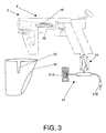
- the invented gun 2 has a gun body 4, a control module 6, a light sensor 8, a trigger circuit 10 with a trigger 12, and a communications interface 14 to a computer game system 16.
- the light sensor 8 detects when a plurality of pixels 18 on a video screen 20 of the computer game system 16 brightens and informs the control module 6 of a detected pixel plurality brightening.
- the control module 6 then processes the time occurrence of the detected pixels brightening in combination with signals received from the trigger circuit 10 and information received over the communications bus 14, and therefrom determines, or partially determines, a relatedness, or degree of relatedness, of the detected pixels brightening detection within the context of a computer game scenario running on the computer game system 16.
- the communications interface 14, or comms bus 14, of the invented gun 2 may be a USB, or substantially a USB, or a derivative of a USB, or a variation of a USB, or a modified USB, or a suitable game port system, a MICROSOFT XBOX game system compatible communications interface, or a NINTENDO game system compatible communications bus, or a SONY PLAYSTATION game system compatible communications bus, or an IBM computer system standards compatible communications bus, or an APPLE COMPUTER computer system standards compatible communications bus known in the art, or an IEEE technology society standard compatible communications bus or game port system known in the art , or another suitable communications bus known in the art.
- the control module 6 has a microprocessor 22, a memory-containing gun operating instructions 24, and a processing memory 26 that enable the control module 6 to manage information required for storage and provision to and from the microprocessor 22, or gun processor 22, during the operation of the invented gun.
- the communications bus 14, or comms bus provides bidirectional electrical signal communications between the control module 6 and the computer game system 16.
- the comms bus includes a plurality of signal lines 28, an electrical ground line 30, and a power line 32.
- the invented gun 2 optionally includes a video sampling cable 34 that captures data as this data is transmitted from a computer game system computer 36 to the computer game video screen 20 via a video signal line 38.
- the control module 6 processes this data in view of trigger actuation signals received from the trigger circuit 10 and pixel brightening detection signals received from the light sensor 8. The control module 6 thereby determines where within the video screen 20 the invented gun 2 is pointed proximate to the time that the trigger 12 of the invented gun 2 is manually pulled, depressed or actuated by a game system player.
- the video sampling cable 34 may be included in the comms bus 14 or may be a separate input signal line 34 from the computer game system 16 and to the control module 6 in certain alternate preferred embodiments of the method of the present invention.
- the invented gun 2 further comprises a hand detector 40 that senses the proximity of the game player's hand to a handle 42 of the gun body, or additionally or alternatively, senses the proximity of the game player's hand or finger to the trigger 12 of the gun body 4.
- Manual actuation of the trigger 12 causes the trigger circuit 10 to inform the control module 6 that the game player has chosen to fire or release a simulated round or a simulated burst of rounds within the context of the role of the invented gun 2 within the computer game scenario.
- the hand detector 40 thereby alerts the control module 6 to a grasping of the invented gun 2 by the game player, and of the possibility of an imminent actuation of the trigger 12 by the game player.
- the control module 6 may therefrom select a more appropriate readiness state for the optical gun 2 and thereby more efficiently operate the invented gun 2.
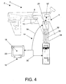
- the invented gun 2 further comprises a peripheral input module 43 that communicates with the optical gun 2, or optionally and more specifically with the gun control module 6, by a communications link 43A.
- the gun peripheral input 43 includes a data input peripheral 43B, such as a thumbpad, a foot pedal, an optical wheel or other suitable data or signal input peripheral known in the art.
- the game player uses the peripheral 43B to indicate choices and selections within the context of a computer game scenario, or to provide information to the optical gun 2 or the computer game system 16.
- the invented optical gun 2 includes a holster 44 and a holster proximity-sensing module 46.
- the invented gun has a small switch 48 of the holster proximity detector 46 on the gun body 4.
- the switch 48 its into a corresponding slot or receptacle 50 in the holster.
- the invented gun 2 detects the state of the switch 48 and may inform the computer game system 16 that the gun 2 is holstered.
- the optical gun 2 includes an interface harness 51 that presents two or more optional hardware connecters 51 A, 51 B to computer game systems 16.
- the addition of more than one type connector 51A, 51B allows the optical gun 2 to be electrically connected with computer game systems 16 of differing make, model or standardized communications bus compatibility.
- the optical gun 2 may be mass produced with a plurality of interface connectors 51A, 51 B, where each connector 51 A, 51 B is selected from a connector type that is compatible with a suitable interface standard known in the art, to include a USB, or a bus that is substantially a USB, or a derivative of a USB, or a variation of a USB, or a modified USB, or a suitable game port system, or a MICROSOFT XBOX game system compatible communications interface, or a NINTENDO game system compatible communications bus, or a SONY PLAYSTATION game system compatible communications bus, or an IBM computer system standards compatible communications bus, or an APPLE COMPUTER computer system standards compatible communications bus known in the art, or an IEEE technology society standard compatible communications bus known in the art, or another suitable standard or proprietary communications bus or game port system known in the art.
- the inclusion of one or more additional interface connectors 51A, 51B with the mass-produced optical gun 2 raises the economic value of the optical gun above the prior art by causing the optical gun to have
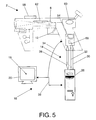
- the invented gun further optionally comprises a recoil simulator 52.
- the recoil simulator 52 may be or may include a small electric motor or actuator that is used to generate a mechanical force.
- the mechanical force is intended to simulate the recoil of an actual weapon to the game player.
- the simulated recoil function may be directed by the computer game system 16 or the gun processor 22, and the command to simulate a weapon's recoil may be transmitted over the comms bus 14 and from the computer game system 16.
- the simulated recoil function may be used in various preferred embodiments of the method of the present invention to inform, reinforce or add to a game scenario ambience when the control module 6 and/or computer game system 16 determines (1) that the game player has effected a simulated hit on a target, (2) that the game player has been hit within the context of the game scenario, or (3) whenever the game player has effected a simulated firing of the invented gun.
- the invented gun includes a battery 54 and a battery charging system 56.
- the battery 54 supplies electrical power to the invented gun 2 and to the recoil simulator 52.
- the battery 54 enables the optical gun 2 to provide a quantity of electrical power to elements of the invented gun 2 in excess of the amount of energy that the communications bus, such as a USB or USB-like communications bus, can instantaneously provide from the game system 16 and to the optical gun 2.
- the battery charging system 56 recharges the battery 54 by channeling electrical power received from the communications bus 14 into the battery.
- the invented gun 2 may particularly direct the battery charging system 56 to recharge the battery 54 when the gun 2 is sensed to be holstered.
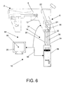
- a laser pointer module 58 of the invented gun provides a laser indicator on the screen of the video screen by generating a laser beam that travels from the invented gun 2 and to the screen 20.
- the invented gun 2 fires the laser beam when the optical sensor 8 indicates that the gun 2 is pointed at the screen 20 such that the beam will hit the screen.
- the invented gun 2 will turn off the laser, or cause the laser beam to not exit from the invented gun 2, when the optical sensor 8 indicates that the gun 2 is not pointed at the screen 20.
- This optional inventive feature of the method of the present invention enables the invented gun 2 to reduce or eliminate the intersection of the laser beam with objects, person or surfaces other than the video screen 20.
- the location of the intersection of the laser beam with the video screen 20 may be used to aid the player in orienting within a game scenario or in improving the accuracy of simulated firing of the invented gun 2.
- the invented gun 2 receives instructions from the computer game system 16 to turn on or turn off the laser point via information enclosed in messages, such as in a USB OUT packet or packets , comms bus commands or other communication methods.
- the invented gun 2 includes a character or avatar detection indicator 60.
- the character or avatar detection indicator, or presence indicator 60 indicates to the game player the presence or approach of a character or avatar within the game scenario, and may indicate a characteristic or state of the character or avatar, such as by using colored lighted to indicate the state of the character or avatar, e.g., wounded, angry, or sleeping, or whether a particular avatar or character is a friend, an ally, a foe, a neutral entity or an innocent or unidentified party.
- the presence indicator 60 indicates the characteristic when the optical gun is pointed at the character or avatar.
- the invented gun further includes a the zoom control that activates a zoom function, whereby the interaction of the game player within a computer game scenario is affected by manual manipulations of the zoom control 62, and a screen image of the video display 20 of the computer game system 16 is affected function.
- the orientation or simulated location of the game player within a game scenario is affected by manual manipulations of zoom control features 62 positioned on the optical gun 2.
- the zoom function may affect the field of view presented to the game player by the computer game system 16, whereby the game player may elect to have a more limited field of view but with a larger presentation of one or more visual elements of the game scenario.
- the actuation and manipulation of the zoom control feature 62 is reported to the computer game system 16 via the comms bus 14.
- the invented system 2 uses the data received from the computer game system 16 and via the video sampling cable 34 to improve the interaction of the present invention with a computer game system 16 that includes a digital television 64.
- the preferred embodiment of the method of the present invention as actualized in the invented gun 2 removes the phase angle of a digital television image calculation in a optional software technique by (1) recognizing that the invented gun 2 and the screen 20 are to a large degree always out of phase, (2) calculating this phase angle on a composite sync per-frame basis and then (3) mathematically reducing the offset to zero.
- the software and high-speed digital hardware elements of the gun 2 are both employed to actualize this optional aspect of the method of the present invention.
- the identification and measurement of certain mathematical values, the calculation of phase angles, frame rates and the resultant accuracy to a large degree depend on a physical principle in mathematics called the beat frequency.
- the photo detector 8 of the invented gun 2 observes a beat frequency which is the composite of these two signals, i.e. FI(t) and FS(t).
- the preferred embodiment of the method of the present invention is directed to find the values of w2 and q.
- the instantaneous phase angle of these two functions as composed to P(t) is the solution.
- the processor in the invented does not attempt to solve the equation.
- the invented gun 2 employs a table driven method whereby the magnitude
- T 1/w2, where w2 is expressed in hertz.
- the optical gun 2 transmits the value of q and/or T to the computer game system 16, whereby the computer game system 16 can calculate the time offset imposed by a digital television and the images displayed on the video screen 20.
- the optical gun 2 further observes the number of Vsync counts that occur between the start of a frame and the detection of a particular instance of pixel or area brightening of the video screen 20 and transmits the Vsync count to the computer game system 16 via the computer game system 16.
- the preferred embodiment additionally detects the Hsync count of a width of an area brightening of the video screen 20 and transmits this Hsync count to the computer game system 16 via the communications interface 14.
- the Hsync count is then used to determine the center of the brightening of the area of the video screen 20, from which determination the orientation of the optical gun 2 to the video screen 20 is more closely determined.
- Certain preferred embodiments of the method of the present invention resolves the true offset T where two fundamental frequencies w1 and w2 are quantified. Additionally and optionally, having derived the fundamental beat frequency of these two functions, this optional aspect of the method of the present invention can pick any point in a measurement range to produce a desired result by recognizing and accommodating for a change, and an instantaneous value, of the phase angle y.
- all computational mathematics performed by the invented optical gun processor 22 are executed with 32-bit, two's complement, fixed point notation.
- the single measurement point may be taken at random.
- alternative preferred embodiments of the method of the present invention may comprise bidirectional or unidirectional wireless communication with the computer game system 16.
- the alternate preferred embodiment of the method of the present invention of FIG. 8A, or unidirectional wireless gun 66 includes a wireless transmitter 68, and the computer game system 16 includes a wireless receiver 70.
- the transmitter 68 sends information about the optical gun's 66 state or detected conditions and sends the information to the receiver 70 of the computer game system 16 by infrared or radio frequency 71, or other suitable wireless transmission means known in the art.
- the receiver includes a wireless receiver module 70A, a digital logic module 70B and a receiver-to-game system interface 70C.
- the receiver 70 accepts the information transmitted from the optical gun 66 via the wireless receiver module 70A.
- the digital logic module 70B then formats a receiver data report that includes the transmitted information.
- the receiver 70 then sends the receiver data report to the computer game system 16 via the receiver-to-game system interface 70C.
- the receiver-to-game system interface 70C and the receiver data report may be USB compliant or substantially USB compliant, or be configured or function in accordance with a suitable industry standard or proprietary communications bus as stipulated by MICROSOFT CORPORATION, SONY, SEGA, NINTENDO, IBM or the IEEE, or another suitable communications protocol or game port system known in the art.
- a second alternate preferred embodiment of the method of the present invention, or bidirectional wireless gun 72, of FIG. 8B includes a gun transceiver 74 in the bidirectional wireless gun 72 and a game transceiver 76 coupled with the computer game system 16.
- the optical gun transceiver 74 sends and receives information from and to the game transceiver 76.
- the optical gun transceiver 74 sends gun information about the optical gun's 72 state or detected conditions and sends the gun information to the transceiver 76 of the computer game system 16 by infrared or radio frequency 75, or other suitable wireless transmission means known in the art.
- the game transceiver 76 includes a wireless transceiver module 76A, a digital logic module 76B and a receiver-to-game system interface 76C.
- the game transceiver 76 accepts the gun information transmitted from the optical gun 72 via the wireless transceiver module 76A.
- the digital logic module 76B then formats a receiver data report that includes the transmitted gun information.
- the game transceiver 76 then sends the receiver data report to the computer game system 16 via the transceiver-to-game system interface 76C.
- the transceiver-to-game system interface 76C and the receiver data report may be USB compliant or substantially USB compliant, or be configured and function in accordance with a suitable industry standard or proprietary communications bus as stipulated by MICROSOFT CORPORATION, SONY, SEGA, NINTENDO, IBM or the IEEE, or another suitable communications protocol or game port system known in the art.
- the game transceiver may additionally transmit data or instruction to the optical gun by suitable wireless transmission means known in the art, such as radio frequency or infrared transmission.
- the receiver 70, transmitter 68 and transceivers 74, 76 may each further comprise a channel selector 77, whereby a user decides which channel may be used by a particular wireless optical gun 66, 72 to transmit or receive wireless signals to and from the computer game system 16.
- This optional capability facilitates the use of two or more optical guns 66, 72 simultaneously with the computer game system 16 by dedicated separate wireless transmission frequencies or band to individual optical guns 66, 72.
- the channel selector may be a manual selector, whereby the game player manually selects the channel for use by the gun 2 by moving a manual switch to a pre-established position.
- the unidirectional wireless gun 66 and the bidirectional wireless gun 72 each have a multiple channel auto detect, or a channel select switch, to select a radio frequency for information transmission.
- These wireless embodiments 66, 72 may also have a battery charger 78, whereby the battery 54 of the optical gun is charged with electrical power by removably connecting a power source or outlet to the battery 54 via the battery charger 78.
- the gun control module 6 may be integrated in a single chip solution that comprises a suitable semiconductor processor device, such as a Microchip 16C745/16C765, or a Cypress 630001 A, or suitable derivatives thereof, or another suitable electronic device known in the art.
- a suitable semiconductor processor device such as a Microchip 16C745/16C765, or a Cypress 630001 A, or suitable derivatives thereof, or another suitable electronic device known in the art.
- Certain preferred embodiments of the method of the present invention having a single chip, device or multi-chip module comprised by gun control module 6 include the following elements and features within or associated with the control module 6:
Landscapes
- Engineering & Computer Science (AREA)
- Multimedia (AREA)
- Human Computer Interaction (AREA)
- General Engineering & Computer Science (AREA)
- Physics & Mathematics (AREA)
- Theoretical Computer Science (AREA)
- Optics & Photonics (AREA)
- General Physics & Mathematics (AREA)
- Computer Networks & Wireless Communication (AREA)
- Position Input By Displaying (AREA)
- Controls And Circuits For Display Device (AREA)
- Aiming, Guidance, Guns With A Light Source, Armor, Camouflage, And Targets (AREA)
- Toys (AREA)
Applications Claiming Priority (2)
| Application Number | Priority Date | Filing Date | Title |
|---|---|---|---|
| US09/947,479 US20020010021A1 (en) | 1999-08-03 | 2001-09-06 | Method and device for optical gun interaction with a computer game system |
| US947479 | 2001-09-06 |
Publications (2)
| Publication Number | Publication Date |
|---|---|
| EP1293237A2 true EP1293237A2 (fr) | 2003-03-19 |
| EP1293237A3 EP1293237A3 (fr) | 2004-04-14 |
Family
ID=25486202
Family Applications (1)
| Application Number | Title | Priority Date | Filing Date |
|---|---|---|---|
| EP01309777A Withdrawn EP1293237A3 (fr) | 2001-09-06 | 2001-11-21 | Procédé et dispositif pour l'interaction d'une arme optique avec un système de jeux par ordinateur |
Country Status (2)
| Country | Link |
|---|---|
| US (3) | US20020010021A1 (fr) |
| EP (1) | EP1293237A3 (fr) |
Cited By (18)
| Publication number | Priority date | Publication date | Assignee | Title |
|---|---|---|---|---|
| EP1757345A1 (fr) * | 2005-08-24 | 2007-02-28 | Nintendo Co., Limited | Controlleur de jeu vidéo et système de jeu vidéo |
| EP1759745A1 (fr) * | 2005-08-30 | 2007-03-07 | Nintendo Co., Ltd. | Système de jeu vidéo, et support d'enregistrement avec programme de jeu vidéo |
| GB2446637A (en) * | 2007-02-13 | 2008-08-20 | David Andrew Morris | Communication system range control arrangement |
| GB2446636A (en) * | 2007-02-13 | 2008-08-20 | David Andrew Morris | Infra-red tag identification / communication system |
| US7698096B2 (en) | 2008-01-21 | 2010-04-13 | Nintendo Co., Ltd. | Information processing apparatus, storage medium, and methodology for calculating an output value based on a tilt angle of an input device |
| WO2010080766A2 (fr) * | 2009-01-06 | 2010-07-15 | Immersion Corporation | Contrôleur de pistolet à activation haptique pour jeu programmable |
| US8907889B2 (en) | 2005-01-12 | 2014-12-09 | Thinkoptics, Inc. | Handheld vision based absolute pointing system |
| US8913003B2 (en) | 2006-07-17 | 2014-12-16 | Thinkoptics, Inc. | Free-space multi-dimensional absolute pointer using a projection marker system |
| US9039533B2 (en) | 2003-03-25 | 2015-05-26 | Creative Kingdoms, Llc | Wireless interactive game having both physical and virtual elements |
| US9176598B2 (en) | 2007-05-08 | 2015-11-03 | Thinkoptics, Inc. | Free-space multi-dimensional absolute pointer with improved performance |
| US9675878B2 (en) | 2004-09-29 | 2017-06-13 | Mq Gaming, Llc | System and method for playing a virtual game by sensing physical movements |
| US9700806B2 (en) | 2005-08-22 | 2017-07-11 | Nintendo Co., Ltd. | Game operating device |
| US9713766B2 (en) | 2000-02-22 | 2017-07-25 | Mq Gaming, Llc | Dual-range wireless interactive entertainment device |
| US9731194B2 (en) | 1999-02-26 | 2017-08-15 | Mq Gaming, Llc | Multi-platform gaming systems and methods |
| US9931578B2 (en) | 2000-10-20 | 2018-04-03 | Mq Gaming, Llc | Toy incorporating RFID tag |
| US9993724B2 (en) | 2003-03-25 | 2018-06-12 | Mq Gaming, Llc | Interactive gaming toy |
| US10010790B2 (en) | 2002-04-05 | 2018-07-03 | Mq Gaming, Llc | System and method for playing an interactive game |
| US10478719B2 (en) | 2002-04-05 | 2019-11-19 | Mq Gaming, Llc | Methods and systems for providing personalized interactive entertainment |
Families Citing this family (48)
| Publication number | Priority date | Publication date | Assignee | Title |
|---|---|---|---|---|
| CN1098719C (zh) * | 1999-12-03 | 2003-01-15 | 北京康体休闲设备开发中心 | 模拟激光射击系统 |
| JP2002058874A (ja) * | 2000-08-15 | 2002-02-26 | Mitsumi Electric Co Ltd | コントロールアダプタ装置 |
| FI20002841A (fi) * | 2000-12-22 | 2002-06-23 | Nokia Corp | Menetelmä päätelaitteen näytön ohjaamiseksi |
| KR20020093291A (ko) * | 2001-06-08 | 2002-12-16 | 김범 | 스크린 상의 목표물 위치 감지 장치 |
| JP2004008559A (ja) * | 2002-06-07 | 2004-01-15 | Nec Corp | 電子競技ネットワークシステム、電子競技方法、並びにサーバ及びコンピュータプログラム |
| JP3902513B2 (ja) * | 2002-06-07 | 2007-04-11 | 日本電気株式会社 | 光銃 |
| US7674184B2 (en) | 2002-08-01 | 2010-03-09 | Creative Kingdoms, Llc | Interactive water attraction and quest game |
| US7291014B2 (en) * | 2002-08-08 | 2007-11-06 | Fats, Inc. | Wireless data communication link embedded in simulated weapon systems |
| US7168198B2 (en) * | 2003-06-23 | 2007-01-30 | Reginald Hill Newkirk | Gun with user notification |
| US7510477B2 (en) * | 2003-12-11 | 2009-03-31 | Argentar Eric J | Control apparatus for use with a computer or video game system |
| US8070571B2 (en) * | 2003-12-11 | 2011-12-06 | Eric Argentar | Video game controller |
| JP4179162B2 (ja) * | 2003-12-26 | 2008-11-12 | 株式会社セガ | 情報処理装置、ゲーム装置、画像生成方法、ゲーム画像生成方法 |
| US20050174337A1 (en) * | 2004-02-11 | 2005-08-11 | Nielsen Paul S. | Electronic handheld drawing and gaming system using television monitor |
| TWI261525B (en) * | 2004-12-24 | 2006-09-11 | Giga Byte Tech Co Ltd | Motion analyzing device and method for mobile product |
| US20060172801A1 (en) | 2005-01-31 | 2006-08-03 | Saied Hussaini | Video game controller with rechargeable battery system |
| US20070202950A1 (en) * | 2005-03-04 | 2007-08-30 | Saied Hussaini | Wireless game controller with integrated audio system |
| US8651964B2 (en) * | 2005-04-29 | 2014-02-18 | The United States Of America As Represented By The Secretary Of The Army | Advanced video controller system |
| US20060277466A1 (en) * | 2005-05-13 | 2006-12-07 | Anderson Thomas G | Bimodal user interaction with a simulated object |
| US8313379B2 (en) | 2005-08-22 | 2012-11-20 | Nintendo Co., Ltd. | Video game system with wireless modular handheld controller |
| US7942745B2 (en) | 2005-08-22 | 2011-05-17 | Nintendo Co., Ltd. | Game operating device |
| US7927216B2 (en) | 2005-09-15 | 2011-04-19 | Nintendo Co., Ltd. | Video game system with wireless modular handheld controller |
| US8870655B2 (en) | 2005-08-24 | 2014-10-28 | Nintendo Co., Ltd. | Wireless game controllers |
| CN1919389A (zh) * | 2005-08-24 | 2007-02-28 | 任天堂株式会社 | 游戏控制器和游戏系统 |
| US8308563B2 (en) | 2005-08-30 | 2012-11-13 | Nintendo Co., Ltd. | Game system and storage medium having game program stored thereon |
| US8157651B2 (en) | 2005-09-12 | 2012-04-17 | Nintendo Co., Ltd. | Information processing program |
| JP4151982B2 (ja) | 2006-03-10 | 2008-09-17 | 任天堂株式会社 | 動き判別装置および動き判別プログラム |
| US7459624B2 (en) | 2006-03-29 | 2008-12-02 | Harmonix Music Systems, Inc. | Game controller simulating a musical instrument |
| US7976387B2 (en) * | 2006-04-11 | 2011-07-12 | Avago Technologies General Ip (Singapore) Pte. Ltd. | Free-standing input device |
| US9958934B1 (en) * | 2006-05-01 | 2018-05-01 | Jeffrey D. Mullen | Home and portable augmented reality and virtual reality video game consoles |
| JP5153122B2 (ja) * | 2006-11-15 | 2013-02-27 | 任天堂株式会社 | ゲームプログラムおよびゲーム装置 |
| US7625284B2 (en) | 2007-06-14 | 2009-12-01 | Harmonix Music Systems, Inc. | Systems and methods for indicating input actions in a rhythm-action game |
| US8663013B2 (en) | 2008-07-08 | 2014-03-04 | Harmonix Music Systems, Inc. | Systems and methods for simulating a rock band experience |
| US8449360B2 (en) | 2009-05-29 | 2013-05-28 | Harmonix Music Systems, Inc. | Displaying song lyrics and vocal cues |
| US9981193B2 (en) | 2009-10-27 | 2018-05-29 | Harmonix Music Systems, Inc. | Movement based recognition and evaluation |
| US10357714B2 (en) | 2009-10-27 | 2019-07-23 | Harmonix Music Systems, Inc. | Gesture-based user interface for navigating a menu |
| US8874243B2 (en) | 2010-03-16 | 2014-10-28 | Harmonix Music Systems, Inc. | Simulating musical instruments |
| US9180365B2 (en) * | 2010-05-10 | 2015-11-10 | Sony Computer Entertainment America Llc | Polymorphic firearm controller |
| EP2579955B1 (fr) | 2010-06-11 | 2020-07-08 | Harmonix Music Systems, Inc. | Jeu de danse et cours de tanz |
| JP5622447B2 (ja) * | 2010-06-11 | 2014-11-12 | 任天堂株式会社 | 情報処理プログラム、情報処理装置、情報処理システム及び情報処理方法 |
| US8562403B2 (en) | 2010-06-11 | 2013-10-22 | Harmonix Music Systems, Inc. | Prompting a player of a dance game |
| US9358456B1 (en) | 2010-06-11 | 2016-06-07 | Harmonix Music Systems, Inc. | Dance competition game |
| US9024166B2 (en) | 2010-09-09 | 2015-05-05 | Harmonix Music Systems, Inc. | Preventing subtractive track separation |
| JP5986738B2 (ja) * | 2011-11-30 | 2016-09-06 | 株式会社スクウェア・エニックス | ビデオゲーム処理装置、およびビデオゲーム処理プログラム |
| CN102935288B (zh) * | 2012-10-31 | 2015-04-22 | 深圳市德力信科技有限公司 | 一种人机互动游戏实现装置及方法 |
| US20140162584A1 (en) * | 2012-12-09 | 2014-06-12 | Sammy Cope | Safety gun holster |
| US10451376B2 (en) | 2014-12-16 | 2019-10-22 | Kurt S. SCHULZ | Firearm simulators |
| CN104573664A (zh) * | 2015-01-21 | 2015-04-29 | 深圳华侨城文化旅游科技有限公司 | 一种射击路径的3d场景重构系统及方法 |
| CN112752945A (zh) * | 2018-07-02 | 2021-05-04 | 梦境沉浸股份有限公司 | 用于虚拟现实系统的枪械模拟布置 |
Citations (5)
| Publication number | Priority date | Publication date | Assignee | Title |
|---|---|---|---|---|
| FR2312274A1 (fr) * | 1975-05-30 | 1976-12-24 | Laurenti Edmond | Jeu de tir au revolver |
| US5569085A (en) | 1994-07-29 | 1996-10-29 | Namco Limited | Gun game machine having a sliding gun barrel cover for simulating the impact of a fired gun |
| GB2340589A (en) * | 1998-08-07 | 2000-02-23 | Hilary Barbara Cannon | Weapon security system |
| EP0985899A1 (fr) * | 1998-09-09 | 2000-03-15 | Mitsubishi Denki Kabushiki Kaisha | Enregistreur vidéo pour une arme ciblable |
| US6171190B1 (en) | 1998-05-27 | 2001-01-09 | Act Labs, Ltd. | Photosensitive input peripheral device in a personal computer-based video gaming platform |
Family Cites Families (38)
| Publication number | Priority date | Publication date | Assignee | Title |
|---|---|---|---|---|
| US4157182A (en) * | 1977-01-10 | 1979-06-05 | Levine Alfred B | Falling target light game and target practice device |
| JPS61156405A (ja) * | 1984-12-28 | 1986-07-16 | Nintendo Co Ltd | 光感応制御装置 |
| US4813682A (en) * | 1985-08-09 | 1989-03-21 | Nintendo Co., Ltd. | Video target control and sensing circuit for photosensitive gun |
| CA1284225C (fr) * | 1986-07-23 | 1991-05-14 | Katsuya Nakagawa | Systeme a ludiciels |
| US5026158A (en) * | 1988-07-15 | 1991-06-25 | Golubic Victor G | Apparatus and method for displaying and storing impact points of firearm projectiles on a sight field of view |
| JPH04259482A (ja) * | 1991-02-14 | 1992-09-16 | Taito Corp | 目標位置検出装置 |
| US5224860A (en) * | 1991-03-01 | 1993-07-06 | Electronics & Space Corp. | Hardware-in-the-loop tow missile system simulator |
| US5544338A (en) * | 1992-12-31 | 1996-08-06 | International Business Machines Corporation | Apparatus and method for raster generation from sparse area array output |
| US5602932A (en) * | 1994-03-04 | 1997-02-11 | International Business Machines Corporation | Photodetector array based image analysis apparatus |
| JPH0869274A (ja) * | 1994-08-30 | 1996-03-12 | Sega Enterp Ltd | 画像処理装置およびその方法 |
| US5926168A (en) * | 1994-09-30 | 1999-07-20 | Fan; Nong-Qiang | Remote pointers for interactive televisions |
| US5638085A (en) * | 1995-01-13 | 1997-06-10 | Micron Display Technology, Inc. | Timing control for a matrixed scanned array |
| JPH09152307A (ja) * | 1995-12-01 | 1997-06-10 | Sega Enterp Ltd | 座標検出装置、その方法およびゲーム装置 |
| JP3140971B2 (ja) * | 1996-10-17 | 2001-03-05 | 株式会社ナムコ | ゲームコントローラ |
| US6280323B1 (en) * | 1996-11-21 | 2001-08-28 | Konami Co., Ltd. | Device, method and storage medium for displaying penalty kick match cursors in a video soccer game |
| US6146278A (en) * | 1997-01-10 | 2000-11-14 | Konami Co., Ltd. | Shooting video game machine |
| US5999171A (en) * | 1997-06-19 | 1999-12-07 | Vlsi Technology, Inc. | Detection of objects on a computer display |
| US5995112A (en) * | 1997-06-19 | 1999-11-30 | Vlsi Technology, Inc. | Color signature detection of objects on a computer display |
| US6720949B1 (en) * | 1997-08-22 | 2004-04-13 | Timothy R. Pryor | Man machine interfaces and applications |
| US5958020A (en) * | 1997-10-29 | 1999-09-28 | Vlsi Technology, Inc. | Real time event determination in a universal serial bus system |
| JP3269797B2 (ja) * | 1997-12-12 | 2002-04-02 | 株式会社ナムコ | 画像生成装置及び情報記憶媒体 |
| KR100313692B1 (ko) * | 1998-01-16 | 2001-11-15 | 가나이 쓰토무 | 줌 확대 기능을 갖는 영상 장치 및 영상 장치의 줌 화상 생성 방법 |
| DE19801732A1 (de) * | 1998-01-19 | 1999-07-22 | Thomson Brandt Gmbh | Schaltung zur Aufbereitung von Synchronsignalen |
| US6261180B1 (en) * | 1998-02-06 | 2001-07-17 | Toymax Inc. | Computer programmable interactive toy for a shooting game |
| DE69928751T2 (de) * | 1998-05-13 | 2006-09-14 | Sega Corp. | Pistolenförmiger Regler |
| US6178514B1 (en) * | 1998-07-31 | 2001-01-23 | Bradley C. Wood | Method and apparatus for connecting a device to a bus carrying power and a signal |
| JP3662435B2 (ja) * | 1998-12-17 | 2005-06-22 | コナミ株式会社 | 射的ビデオゲーム装置 |
| US6328651B1 (en) * | 1999-02-03 | 2001-12-11 | Toymax Inc. | Projected image target shooting toy |
| US6346938B1 (en) * | 1999-04-27 | 2002-02-12 | Harris Corporation | Computer-resident mechanism for manipulating, navigating through and mensurating displayed image of three-dimensional geometric model |
| US6545661B1 (en) * | 1999-06-21 | 2003-04-08 | Midway Amusement Games, Llc | Video game system having a control unit with an accelerometer for controlling a video game |
| US6287198B1 (en) * | 1999-08-03 | 2001-09-11 | Mccauley Jack J. | Optical gun for use with computer games |
| US6592461B1 (en) * | 2000-02-04 | 2003-07-15 | Roni Raviv | Multifunctional computer interactive play system |
| JP3527676B2 (ja) * | 2000-02-16 | 2004-05-17 | 株式会社ナムコ | 位置指示装置及び情報記憶媒体 |
| US6899539B1 (en) * | 2000-02-17 | 2005-05-31 | Exponent, Inc. | Infantry wearable information and weapon system |
| US6386879B1 (en) * | 2000-03-24 | 2002-05-14 | Cubic Defense Systems, Inc. | Precision gunnery simulator system and method |
| US6814667B2 (en) * | 2001-07-27 | 2004-11-09 | Robert W. Jeffway, Jr. | eTroops infrared shooting game |
| TWI232769B (en) * | 2001-10-19 | 2005-05-21 | Zeroplus Technology Co Ltd | Visual feedback system for light gun |
| US6902483B2 (en) * | 2002-04-01 | 2005-06-07 | Xiao Lin | Handheld electronic game device having the shape of a gun |
-
2001
- 2001-09-06 US US09/947,479 patent/US20020010021A1/en not_active Abandoned
- 2001-11-21 EP EP01309777A patent/EP1293237A3/fr not_active Withdrawn
-
2003
- 2003-05-08 US US10/431,866 patent/US20030199317A1/en not_active Abandoned
- 2003-05-08 US US10/431,867 patent/US20030195041A1/en not_active Abandoned
Patent Citations (5)
| Publication number | Priority date | Publication date | Assignee | Title |
|---|---|---|---|---|
| FR2312274A1 (fr) * | 1975-05-30 | 1976-12-24 | Laurenti Edmond | Jeu de tir au revolver |
| US5569085A (en) | 1994-07-29 | 1996-10-29 | Namco Limited | Gun game machine having a sliding gun barrel cover for simulating the impact of a fired gun |
| US6171190B1 (en) | 1998-05-27 | 2001-01-09 | Act Labs, Ltd. | Photosensitive input peripheral device in a personal computer-based video gaming platform |
| GB2340589A (en) * | 1998-08-07 | 2000-02-23 | Hilary Barbara Cannon | Weapon security system |
| EP0985899A1 (fr) * | 1998-09-09 | 2000-03-15 | Mitsubishi Denki Kabushiki Kaisha | Enregistreur vidéo pour une arme ciblable |
Cited By (48)
| Publication number | Priority date | Publication date | Assignee | Title |
|---|---|---|---|---|
| US10300374B2 (en) | 1999-02-26 | 2019-05-28 | Mq Gaming, Llc | Multi-platform gaming systems and methods |
| US9731194B2 (en) | 1999-02-26 | 2017-08-15 | Mq Gaming, Llc | Multi-platform gaming systems and methods |
| US9861887B1 (en) | 1999-02-26 | 2018-01-09 | Mq Gaming, Llc | Multi-platform gaming systems and methods |
| US10188953B2 (en) | 2000-02-22 | 2019-01-29 | Mq Gaming, Llc | Dual-range wireless interactive entertainment device |
| US10307671B2 (en) | 2000-02-22 | 2019-06-04 | Mq Gaming, Llc | Interactive entertainment system |
| US9713766B2 (en) | 2000-02-22 | 2017-07-25 | Mq Gaming, Llc | Dual-range wireless interactive entertainment device |
| US9814973B2 (en) | 2000-02-22 | 2017-11-14 | Mq Gaming, Llc | Interactive entertainment system |
| US10307683B2 (en) | 2000-10-20 | 2019-06-04 | Mq Gaming, Llc | Toy incorporating RFID tag |
| US9931578B2 (en) | 2000-10-20 | 2018-04-03 | Mq Gaming, Llc | Toy incorporating RFID tag |
| US10179283B2 (en) | 2001-02-22 | 2019-01-15 | Mq Gaming, Llc | Wireless entertainment device, system, and method |
| US10758818B2 (en) | 2001-02-22 | 2020-09-01 | Mq Gaming, Llc | Wireless entertainment device, system, and method |
| US9737797B2 (en) | 2001-02-22 | 2017-08-22 | Mq Gaming, Llc | Wireless entertainment device, system, and method |
| US10478719B2 (en) | 2002-04-05 | 2019-11-19 | Mq Gaming, Llc | Methods and systems for providing personalized interactive entertainment |
| US10507387B2 (en) | 2002-04-05 | 2019-12-17 | Mq Gaming, Llc | System and method for playing an interactive game |
| US10010790B2 (en) | 2002-04-05 | 2018-07-03 | Mq Gaming, Llc | System and method for playing an interactive game |
| US11278796B2 (en) | 2002-04-05 | 2022-03-22 | Mq Gaming, Llc | Methods and systems for providing personalized interactive entertainment |
| US9770652B2 (en) | 2003-03-25 | 2017-09-26 | Mq Gaming, Llc | Wireless interactive game having both physical and virtual elements |
| US9039533B2 (en) | 2003-03-25 | 2015-05-26 | Creative Kingdoms, Llc | Wireless interactive game having both physical and virtual elements |
| US9993724B2 (en) | 2003-03-25 | 2018-06-12 | Mq Gaming, Llc | Interactive gaming toy |
| US10369463B2 (en) | 2003-03-25 | 2019-08-06 | Mq Gaming, Llc | Wireless interactive game having both physical and virtual elements |
| US9707478B2 (en) | 2003-03-25 | 2017-07-18 | Mq Gaming, Llc | Motion-sensitive controller and associated gaming applications |
| US11052309B2 (en) | 2003-03-25 | 2021-07-06 | Mq Gaming, Llc | Wireless interactive game having both physical and virtual elements |
| US10583357B2 (en) | 2003-03-25 | 2020-03-10 | Mq Gaming, Llc | Interactive gaming toy |
| US10022624B2 (en) | 2003-03-25 | 2018-07-17 | Mq Gaming, Llc | Wireless interactive game having both physical and virtual elements |
| US9675878B2 (en) | 2004-09-29 | 2017-06-13 | Mq Gaming, Llc | System and method for playing a virtual game by sensing physical movements |
| US8907889B2 (en) | 2005-01-12 | 2014-12-09 | Thinkoptics, Inc. | Handheld vision based absolute pointing system |
| US10661183B2 (en) | 2005-08-22 | 2020-05-26 | Nintendo Co., Ltd. | Game operating device |
| US9700806B2 (en) | 2005-08-22 | 2017-07-11 | Nintendo Co., Ltd. | Game operating device |
| US10238978B2 (en) | 2005-08-22 | 2019-03-26 | Nintendo Co., Ltd. | Game operating device |
| US10155170B2 (en) | 2005-08-22 | 2018-12-18 | Nintendo Co., Ltd. | Game operating device with holding portion detachably holding an electronic device |
| US10137365B2 (en) | 2005-08-24 | 2018-11-27 | Nintendo Co., Ltd. | Game controller and game system |
| EP1757345A1 (fr) * | 2005-08-24 | 2007-02-28 | Nintendo Co., Limited | Controlleur de jeu vidéo et système de jeu vidéo |
| CN101837191B (zh) * | 2005-08-24 | 2012-02-08 | 任天堂株式会社 | 游戏控制器和游戏系统 |
| US11027190B2 (en) | 2005-08-24 | 2021-06-08 | Nintendo Co., Ltd. | Game controller and game system |
| EP2292305A1 (fr) * | 2005-08-24 | 2011-03-09 | Nintendo Co., Ltd. | Controlleur de jeu vidéo et système de jeu vidéo |
| US9044671B2 (en) | 2005-08-24 | 2015-06-02 | Nintendo Co., Ltd. | Game controller and game system |
| KR101169813B1 (ko) | 2005-08-30 | 2012-07-30 | 닌텐도가부시키가이샤 | 게임 시스템 및 게임 프로그램을 저장한 저장 매체 |
| EP1759745A1 (fr) * | 2005-08-30 | 2007-03-07 | Nintendo Co., Ltd. | Système de jeu vidéo, et support d'enregistrement avec programme de jeu vidéo |
| US8913003B2 (en) | 2006-07-17 | 2014-12-16 | Thinkoptics, Inc. | Free-space multi-dimensional absolute pointer using a projection marker system |
| GB2446636A (en) * | 2007-02-13 | 2008-08-20 | David Andrew Morris | Infra-red tag identification / communication system |
| GB2446637A (en) * | 2007-02-13 | 2008-08-20 | David Andrew Morris | Communication system range control arrangement |
| GB2446637B (en) * | 2007-02-13 | 2011-08-10 | David Andrew Morris | Range control for communications systems |
| US9176598B2 (en) | 2007-05-08 | 2015-11-03 | Thinkoptics, Inc. | Free-space multi-dimensional absolute pointer with improved performance |
| US7698096B2 (en) | 2008-01-21 | 2010-04-13 | Nintendo Co., Ltd. | Information processing apparatus, storage medium, and methodology for calculating an output value based on a tilt angle of an input device |
| US9504914B2 (en) | 2009-01-06 | 2016-11-29 | Immersion Corporation | Programmable game-based haptic enabled gun controller |
| WO2010080766A2 (fr) * | 2009-01-06 | 2010-07-15 | Immersion Corporation | Contrôleur de pistolet à activation haptique pour jeu programmable |
| WO2010080766A3 (fr) * | 2009-01-06 | 2010-12-02 | Immersion Corporation | Contrôleur de pistolet à activation haptique pour jeu programmable |
| US8506369B2 (en) | 2009-01-06 | 2013-08-13 | Immersion Corporation | Programmable game-based haptic enabled gun controller |
Also Published As
| Publication number | Publication date |
|---|---|
| EP1293237A3 (fr) | 2004-04-14 |
| US20020010021A1 (en) | 2002-01-24 |
| US20030195041A1 (en) | 2003-10-16 |
| US20030199317A1 (en) | 2003-10-23 |
Similar Documents
| Publication | Publication Date | Title |
|---|---|---|
| EP1293237A2 (fr) | Procédé et dispositif pour l'interaction d'une arme optique avec un système de jeux par ordinateur | |
| US20040259644A1 (en) | Method and device for optical gun interaction with a computer system | |
| JP3140971B2 (ja) | ゲームコントローラ | |
| EP3469466B1 (fr) | Objet à interface directionnelle | |
| US6890262B2 (en) | Video game apparatus, method and recording medium storing program for controlling viewpoint movement of simulated camera in video game | |
| US8100770B2 (en) | Game controller, storage medium storing game program, and game apparatus | |
| EP2569062B1 (fr) | Manette sous la forme d'une arme à feu polymorphique | |
| US7140962B2 (en) | Video game apparatus, image processing method and program | |
| US7896733B2 (en) | Method and apparatus for providing interesting and exciting video game play using a stability/energy meter | |
| US6287198B1 (en) | Optical gun for use with computer games | |
| US5853324A (en) | Shooting game machine and method of computing the same | |
| US20060223635A1 (en) | method and apparatus for an on-screen/off-screen first person gaming experience | |
| JP5389162B2 (ja) | ゲーム装置、ゲーム制御方法、及びゲーム制御プログラム | |
| WO1999058214A1 (fr) | Organe de commande en forme de pistolet et jeu electronique | |
| JP5681633B2 (ja) | 視覚情報を通信するためのコントロールデバイス | |
| WO2012067946A2 (fr) | Coque intelligente destinée à un dispositif de commande de jeu | |
| CN114797085A (zh) | 游戏控制方法及装置、游戏终端及存储介质 | |
| JP2003208263A (ja) | コントロール装置及びその取付け体を有する画像処理装置 | |
| JP2011147672A (ja) | ゲームプログラム、ゲーム装置、制御方法、およびゲームシステム | |
| JP3068487B2 (ja) | 射撃ビデオゲーム装置 | |
| JP3212240B2 (ja) | ゲーム装置及びコマンド入力方法 | |
| JP2002018126A (ja) | ゲームシステム及び情報記憶媒体 | |
| KR200323983Y1 (ko) | 슈팅게임 시스템 | |
| CN114712845A (zh) | 一种智能玩具枪及智能玩具枪对战竞技系统 | |
| EP2420307B1 (fr) | Système de jeu à plusieurs plateformes |
Legal Events
| Date | Code | Title | Description |
|---|---|---|---|
| PUAI | Public reference made under article 153(3) epc to a published international application that has entered the european phase |
Free format text: ORIGINAL CODE: 0009012 |
|
| AK | Designated contracting states |
Kind code of ref document: A2 Designated state(s): AT BE CH CY DE DK ES FI FR GB GR IE IT LI LU MC NL PT SE TR Designated state(s): AT BE CH CY DE DK ES FI FR GB GR IE IT LI LU MC NL PT SE TR |
|
| AX | Request for extension of the european patent |
Extension state: AL LT LV MK RO SI |
|
| PUAL | Search report despatched |
Free format text: ORIGINAL CODE: 0009013 |
|
| AK | Designated contracting states |
Kind code of ref document: A3 Designated state(s): AT BE CH CY DE DK ES FI FR GB GR IE IT LI LU MC NL PT SE TR |
|
| AX | Request for extension of the european patent |
Extension state: AL LT LV MK RO SI |
|
| 17P | Request for examination filed |
Effective date: 20040917 |
|
| AKX | Designation fees paid |
Designated state(s): AT BE CH CY DE DK ES FI FR GB GR IE IT LI LU MC NL PT SE TR |
|
| RAP1 | Party data changed (applicant data changed or rights of an application transferred) |
Owner name: ACTIVISION PUBLISHING, INC. |
|
| RIN1 | Information on inventor provided before grant (corrected) |
Inventor name: MCCAULEY, JACK |
|
| RIC1 | Information provided on ipc code assigned before grant |
Ipc: A63F 13/06 20060101ALI20100324BHEP Ipc: A63F 13/04 20060101ALI20100324BHEP Ipc: A63F 13/02 20060101AFI20100324BHEP |
|
| STAA | Information on the status of an ep patent application or granted ep patent |
Free format text: STATUS: THE APPLICATION IS DEEMED TO BE WITHDRAWN |
|
| 18D | Application deemed to be withdrawn |
Effective date: 20100910 |