BACKGROUND OF THE INVENTION
Field of the Invention
-
The present invention relates to an image
processing apparatus, and more particularly, to an
image processing apparatus which extracts, as a
representative image, a frame from a moving image and
sets it as an index.
Related Background Art
-
Conventionally, as a method of forming an index
image to perform browsing and retrieval of a moving
image, there is the method in which one frame in the
moving image is extracted and set as a representative
image (called a key frame hereinafter), and this
representative image is used as the index image
together with the position thereof in the moving
image.
-
The moving image can be divided into plural units
each called a shot. The shot corresponds to a period
from a photographing start to a photographing end in
case of that the moving image is picked up by a video
camera, and corresponds to a period (one scene) until
a camera angle or the like is switched over in case
of that the moving image is of television
broadcasting. Thus, the method of detecting the
switchover of the shot and setting the headmost frame
of each shot as the index image is well known.
-
However, in fact, if two or more events are
picked up since the camera is panned during one shot,
in order to grasp the contents of this shot, it is
insufficient to set only the headmost frame as the
key frame. Moreover, for example, in a case where a
zoom-in operation starts from the head of the shot
and then continues until the end of the shot to zoom
in an object of interest, the frame after the zoom-in
operation might be more suitable than the headmost
frame as the key frame for the entire shot.
-
As the conventional technique to solve such a
problem, there is a method of extracting the frame
after the zoom-in operation as the key frame by using
camera operation information.
-
As an example of this method, Japanese Patent
Application Laid-Open No. 7-99605 (corresponding to
United States Patent No. 5,581,362) discloses the
technique that, when an image is picked up, the
camera operation information is multiplexed or
combined with video information and stored in a
storage medium, and then, when the stored video
information is reproduced, the frame of satisfying a
specific condition, e.g., after the zoom-in operation,
is set as the key frame. Moreover, Japanese Patent
Application Laid-Open No. 10-224736 discloses the
technique that camera operation information is
discriminated in an image process, and also the frame
of satisfying a specific condition, e.g., after the
zoom-in operation, is set as the key frame.
-
Particularly, when an ordinary user picks up an
image by using a video camera or the like, a smooth
operation is frequently difficult to this user
because he is inexperienced in the camera operation.
For example, in case of performing the zoom-in
operation, the user has to repeat the zoom-in
operations many times until the target image is
enlarged up to a desired size, and moreover he has to
perform also a zoom-out operation. This is because,
since it is difficult to stop the zoom-in operation
just in the desired size, the user has to correct the
excessively zoomed-out image.
-
Here, such zoom-in and zoom-out operations should
be originally considered as a series of operations.
However, in Japanese Patent Application Laid-Open No.
7-99605, the end of the operation is detected in a
case where, after operation information continuously
increases or decreases for a certain number of frames
or more, this information is continuously maintained
without change for a certain number of frames.
-
For this reason, since such an operation as
repeatedly increasing and decreasing the operation
amount, e.g., repeatedly zooming in and out the
images, can not be considered as a series of
operations, there is a problem that a number of
similar images and meaningless images are extracted
as the key frames.
-
Moreover, if a user erroneously handles a zoom
button and thus returns an operation state to its
former state, this is not the operation which is
intended by the user. Thus, in this case, if the key
frame is extracted, this frame merely represents a
meaningless image.
-
However, in Japanese Patent Application Laid-Open
Nos. 7-99605 and 10-224736, there is a problem that
the key frame is extracted even when the operation
not intended by the user or the erroneous operation
as above is performed.
SUMMARY OF THE INVENTION
-
A concern of the present invention is to solve
such problems as above.
-
Another concern of the present invention is to
form an index image which is useful for a user.
-
Still another concern of the present invention is
to form an optimum index image for an image which is
photographed when an camera operation is not smooth.
-
According to an aspect of
the present invention, there is provided an image
processing apparatus comprising:
- an obtaining means for obtaining moving image
data picked up by image pickup means and operation
information concerning an operation condition of the
image pickup means at a time when the moving image
data is picked up;
- a detection means for detecting a predetermined
operation on the basis of the operation information
obtained by the obtaining means;
- a discrimination means for discriminating that a
time interval between the two successive
predetermined operations detected by the detection
means is longer than a predetermined period; and
- an extraction means for extracting image data of
one picture image from the moving image data on the
basis of the discriminated result of the
discrimination means.
-
BRIEF DESCRIPTION OF THE DRAWINGS
-
- Fig. 1 is a block diagram showing the system
structure of a moving image index forming system
according to the first embodiment;
- Fig. 2 is a block diagram showing the functional
structure of a photographing unit according to the
first embodiment;
- Fig. 3 is a block diagram showing the control
structure of an indexing unit according to the first
embodiment;
- Fig. 4 is a block diagram showing the functional
structure of the indexing unit according to the first
embodiment;
- Fig. 5 is a flow chart showing the flow of a
processing procedure in the photographing unit
according to the first embodiment;
- Fig. 6 is a diagram showing an example of a
camera operation information format in a DV format;
- Fig. 7 is a diagram showing an example of the
camera operation information format;
- Fig. 8 is a flow chart showing the flow of a
processing procedure in the indexing unit according
to the first embodiment;
- Fig. 9 is a diagram showing an example of index
information;
- Fig. 10 is a block diagram showing the control
structure of an image processing apparatus for a
moving image according to the second embodiment;
- Fig. 11 is a block diagram showing the functional
structure of the image processing apparatus for the
moving image according to the second embodiment;
- Fig. 12 is a flow chart showing a processing
procedure in the image processing apparatus for the
moving image according to the second embodiment;
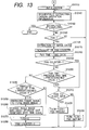
- Fig. 13 is a flow chart showing the processing
procedure in the image processing apparatus for the
moving image according to the second embodiment; and
- Fig. 14 is a diagram for explaining an example of
inter-frame similarity length calculation.
-
DETAILED DESCRIPTION OF THE PREFERRED EMBODIMENTS
-
Hereinafter, the preferred embodiments of the
present invention will be explained in detail with
reference to the attached drawings.
-
Fig. 1 is a block diagram showing the structure
of an image processing apparatus according to the
first embodiment of the present invention. In Fig. 1,
numeral 1010 denotes a photographing unit which
photographs a moving image, numeral 1020 denotes a
recording medium which records therein the moving
image photographed by the photographing unit 1010,
numeral 1030 denotes an indexing unit which extracts
a key frame from image data recorded in the recording
medium 1020 and thus forms an index image.
-
Fig. 2 is a block diagram showing the structure
of the photographing unit 1010 according to the first
embodiment.
-
In Fig. 2, numeral 2010 denotes an image pickup
unit which is composed of a lens, image pickup
elements, an A/D converter and the like. Numeral 2020
denotes an image compression unit which performs a
compression encoding process to a video signal from
the image pickup unit 2010 by using an image
compression circuit, on the basis of an algorithm of
a predetermined compression system. For example, as
an encoding system used in the compression encoding
process, there are the system using orthogonal
transformation and variable length encoding, and the
system using motion compensation prediction such as
MPEG-1, MPEG-2 or the like.
-
Numeral 2030 denotes a camera operation unit
which is composed of a photographing start button, a
zoom button and the like and inputs various camera
operations by a user, numeral 2040 denotes a sensor
unit which is composed of various sensors to detect
the state of a camera and obtains various information
representing opening of a diaphragm, a focal length
and the like, numeral 2050 denotes a control unit
which controls the operation of the image pickup unit
2010 on the basis of operation information obtained
from the camera operation unit 2030 and sensor
information obtained from the sensor unit 2040, and
numeral 2060 denotes a recording unit which
multiplexes video data of the image compression unit
2020 with camera operation information (i.e., the
user's operation information and the sensor
information) at predetermined timing and records the
multiplexed data on a storage medium 2070. Here,
storage medium 2070 stores thereon the multiplexed
video data and camera operation information, and is
composed of a magnetic tape, a magnetooptical disk, a
hard disk or the like.
-
Fig. 3 is a block diagram showing the control
structure of the indexing unit 1030 according to the
first embodiment.
-
In Fig. 3, numeral 301 denotes a CPU which
executes various control in the indexing unit 1030 of
the present embodiment, numeral 302 denotes a ROM
which stores boot programs to be executed when the
image processing apparatus starts and various data,
and numeral 303 denotes a RAM which stores control
programs for the process of the CPU 301 and also
provides a working area when the CPU 301 executes the
various control. Numerals 304 and 305 respectively
denote a keyboard and a mouse which present various
input operation circumstances by the user.
-
Numeral 306 denotes an external storage device
which is composed of a hard disk, a flexible disk, a
CD-ROM and the like, numeral 307 denotes a display
unit which is composed of display and the like and
displays operation results and the like to the user,
numeral 308 denotes a network interface circuit (NIC)
which enables communication with various devices on a
network, and numeral 311 denotes a bus which connects
these devices with others.
-
Fig. 4 is a block diagram showing the functional
structure of the indexing unit 1030 according to the
first embodiment.
-
In Fig. 4, numeral 4020 denotes a camera
operation information integrating unit which reads
out the video data and the camera operation
information from a storage medium 4010 and performs
an integrating process on the operation information
on the basis of time information or the like. That is,
with respect to the camera operation information
representing the same operation content, an
accumulated value of operation amounts represented by
the time-adjacent camera operation information is
calculated. Numeral 4030 denotes a key frame
selection unit which extracts as the key frame the
frame satisfying a predetermined condition on the
basis of the camera operation information (i.e., the
accumulated value of the operation amounts)
integrated by the camera operation information
integrating unit 4020 and thus forms the index image,
when it is considered that the series of operations
completes. Numeral 4040 denotes an index storage unit
which stores index image information generated by the
key frame selection unit 4030.
-
An operation of the image processing apparatus
having the above structure according to the first
embodiment will be explained hereinafter.
-
Fig. 5 is a flow chart showing a processing
procedure in the photographing unit 1010 according to
the first embodiment. First, in a step S8010, it is
discriminated whether or not setting of the camera is
performed by the user through the camera operation
unit 2030. Here, the setting of the camera includes,
e.g., a focus mode (auto/manual), an exposure mode
(auto, gain preference, shutter speed preference,
diaphragm preference, manual), a white balance mode
(auto, hold, one push, preset), and the like.
-
If the setting of the camera is performed, then
the control unit 2050 changes the setting of the
image pickup unit 2010 in a step S8020, and sends the
information representing the changed setting to the
recording unit 2060 as the camera operation
information. Next, it is discriminated in a step
S8030 whether or not a recording button is turned on.
If the recording button is not turned on, the
apparatus is in a standby state, whereby the flow
returns to the step S8010.
-
On the other hand, when the recording button is
turned on, the control unit 2050 sets a recording
state, and sends a recording start time of this
recording to the recording unit 2060 as the camera
operation information. Next, in a step S8040, the
recording by the recording unit 2060 is started
because the apparatus came to be in the recording
state. Thus, the image picked up by the image pickup
unit 2010 is compressed by the image compression unit
2020 and then sent to the recording unit 2060 as the
video data.
-
Next, it is checked in a step S8050 whether or
not the camera operation is performed by the user.
Here, the camera operation includes, e.g., ON/OFF of
a zoom button, pan, tilt and the like. Then, in a
step S8060, the control unit 2050 controls the image
pickup unit 2010 and the like on the basis of the
information sent from the sensor unit 2040.
-
Here, the sensor information includes information
representing, e.g., a focal length, a focusing length,
detected unintentional movement of the hands, and the
like. Then, for example, when a zoom operation is
performed, the image is zoomed in/out by moving the
lens of the image pickup unit 2010 only for the
interval while the zoom button is being depressed,
and then focused on the basis of the sensor
information such as the focal length, the focusing
length and the like. At this time, the sensor
information such as the ON/OFF of the zoom button,
the focal length, the focusing length and the like is
sent to the recording unit 2060 as the camera
operation information. Then, in the recording unit
2060, the video data sent from the image compression
unit 2020 and the camera operation information are
multiplexed with each other and recorded in the
storage medium 2070.
-
As the method of multiplexing the data, the
method standardized in an MPEG-2 system is used. In
the present embodiment, the camera operation
information is converted into a PES (Packetized
Elementary Stream) packet and then multiplexed with a
PES packet of the video data to generate a series of
data strings such as TS (Transport Stream), PS
(Program Stream) or the like and then record the
generated data. Here, the recording unit 2060
generates the corresponding camera operation
information for each frame of the image data, and
multiplexes the generated camera operation
information with the image data as the PES packet
separate from the image data. Next, it is checked in
a step S8070 whether or not the recording button is
OFF. When the recording button is not OFF, the flow
returns to the step S8040, and the apparatus is still
in the photographing state. On the other hand, when
the recording button is OFF, the flow returns to the
step S8010, and the apparatus comes to be in the
standby state.
-
As above, the camera information in the present
embodiment consists of the information obtained from
the camera operation unit 2030 and the information
obtained from the sensor unit 2040. Here, as the
system of describing the camera operation information,
for example, the system of DV format shown in Fig. 6,
the system shown in Fig. 7 or the like can be used.
-
Fig. 8 is a flow chart showing a processing
procedure in the indexing unit 1030 according to the
first embodiment. Here, it should be noted that,
although only the zoom is adopted as the camera
operation information to simplify the explanation,
the same processing procedure is applicable to other
camera operation information.
-
First, in a step S9010, later-described variables
such as a zoom time, TLEN, the value of a zoom
counter and the like are initialized.
-
Next, in a step S9020, the image data string is
read from the storage medium 4010, and then it is
discriminated in a step S9030 whether or not the
read-out operation of the image data is completed. If
the read-out operation of the image data is completed,
then the process is completed, while if the read-out
operation of the image data is not completed, the
flow advances to a next step S9040 to discriminate
whether or not the read-out image data corresponds to
the head of the shot. This can be discriminated
according to whether or not a recording start time
exists. That is, if the recording start time exists
in the frame, this frame can be discriminated as the
frame in which the recording button is turned on.
-
Incidentally, if the read-out image data
corresponds to the head of the shot, then the index
image is formed. Thus, in a step S9130, the size of
the image data of this headmost one frame is reduced
to form the index image. Next, in a step S9140, the
obtained index image data and a time code of the
image data of this one frame are stored as the index
information in the index storage unit 4040.
-
Fig. 9 shows an example of the index information
stored in the index storage unit 4040. Here, a shot
ID represents an ID given for each shot (from turn-on
of a recording button to turn-off thereof recording
button) in due order. Next, the variable TLEN is
initialized to 0 in a step S9120, and then the value
of the zoom counter is initialized to 0 in a step
S9125. The flow then returns to the step S9020.
-
On the other hand, if it is discriminated in the
step S9040 that the read-out image data does not
correspond to the head of the shot, the flow advances
to a step S9050 to discriminate whether or not the
camera operation information representing the zoom
operation is added to the image data of the frame
currently reproduced. If the camera operation
information representing the zoom operation does not
exist, the flow returns to the step S9020, while if
the camera operation information representing the
zoom operation is added, the flow advances to a step
S9051. In the step S9051, the image data of the one
frame corresponding to the camera operation
information representing the zoom operation detected
here is extracted and stored in a memory (not shown)
provided in the apparatus. Besides, also the image
data of the one frame corresponding to the camera
operation information in case of previously detecting
the zoom operation is stored in this memory, and,
every time the zoom operation is detected, the image
data of the one frame corresponding to the detected
camera operation information is written alternately
into storage areas of two frames prepared on the
memory.
-
Next, in a step S9055, the zoom counter is
incremented. As described above, since the ordinary
user is inexperienced in the camera operation, there
is a case where the zoom operations (zoom in and zoom
out) are repeated several times to obtain a desired
zoomed-in image. The value of the zoom counter is the
variable provided to count the number of such the
zoom operations.
-
Next, in a step S9060, the time code of the
extracted image data of the one frame is stored as
the zoom time. In the present embodiment, the zoom
time detected here and the zoom time detected
immediately before are stored in a not-shown memory,
and, every time the zoom time is newly detected, the
newly detected zoom time is overwritten on the
earlier detected zoom time information, so as to
always preserve latest two zoom time information.
-
Next, it is discriminated in a step S9065 whether
or not the value of the zoom counter is one. If the
value of the zoom counter is one (i.e., in case of
the first-time zoom operation), the flow advances to
steps S9080 to S9100 to calculate the variable TLEN.
-
Next, in a step S9070, a difference between the
zoom time detected now and the zoom time detected
one-time before is obtained, and it is further
discriminated whether or not the obtained difference
is equal to or smaller than a predetermined value A.
Here, the value A is the value as follows. As
described above, since the ordinary user is
inexperienced in the camera operation, he frequently
repeats the zoom operations (zoom in and zoom out)
until he obtains the desired zoomed-in image.
-
This series of zoom operations occurs at short
intervals and is completed if the desired zoomed-in
image is obtained. The value A represents the upper
limit of the interval between the successive two zoom
operations which can be considered to be repeated as
above. The value A can be obtained from experience
and, although it is not limited to this, is a short
time about one second or so. In any case, if it is
discriminated in the step S9070 that the time
interval between the successive two zoom operations
is equal to or smaller than the predetermined value A,
since the apparatus is in the state that the zoom
operations are repeated, the processes from the steps
S9080 to S9100 are performed.
-
In the step S9080, it is discriminated whether or
not the camera operation information represents the
zoom-in operation. If the camera operation
information represents the zoom-in operation, the
flow advances to a step S9090 to add a zoom amount to
the variable TLEN. Here, the variable TLEN represents
a substantial zoom-in amount in the series of the
zoom operations, and the zoom amount is the amount of
the period of the zoom operation and can be
represented by the number of frames or the time
period which are weighted by zoom intensity (a rate
of change of a zoom magnification, or movement speed
of a zoom lens).
-
If the camera operation information represents
the zoom-out operation, the zoom amount is subtracted
from the variable TLEN in the step S9100, because the
variable TLEN represents the substantial zoom-in
amount. After the variable TLEN was calculated, the
flow returns to the step S9020.
-
If it is discriminated in the step S9070 that the
time interval is larger than the predetermined value
A, this represents the case where the series of the
zoom operations is completed. At this time, the flow
advances to the step S9110. Then, it is discriminated
in the step S9110 whether or not the absolute value
of the variable TLEN representing the substantial
zoom-in or zoom-out amount is equal to or larger than
a predetermined value B. If this absolute value is
extremely small, this represents that the zoom
operation is hardly performed before and after the
series of the zoom operations. That is, this
corresponds to a case where the user finally stops
performing the zoom operation. Therefore, the
predetermined value B represents the lower-limit
value of the amount which can be recognized to have
been zoomed. Here, the value B can be obtained from
experience and is not specifically limited to such
the value.
-
If the absolute value of the variable TLEN is
smaller than the predetermined value B, since it is
unnecessary to form the index at such a position, the
steps S9130 and S9140 are skipped. On the other hand,
if this absolute value is equal to or larger than the
predetermined value B, it is recognized that the zoom
operation was performed. At this time, one other
image data, i.e., the image data extracted when the
zoom operation was detected last time, which is
stored in the memory together with the image data
stored in the step S9051 is the last image data in
the series of the zoom operations, and the obtained
image is the zoomed-in image which is appropriate as
the index. Thus, the flow advances to the step S9130
to reduce this image data and generate the index
image data.
-
Then, in the step S9140, the time code of that
time and the index image data are stored in the index
storage unit 4040 as the index information. Next, the
variable TLEN is initialized to 0 in the step S9120,
and also the value of the zoom counter is initialized
to 0 in the step S9125. Then, the flow returns to the
step S9020.
-
As explained above, in the present embodiment, in
the case where the interval between the time of the
zoom operation detected this time and the time of the
zoom operation detected last time is equal to or
larger than the predetermined value, the frame,
stored in the memory, at the time of the zoom
operation performed immediately before is extracted
as the index, whereby the frame at the time of the
end of the series of the zoom operations can be
extracted as the index.
-
Therefore, even if the user being inexperienced
in the camera operation repeats the zoom operations,
the index appropriately representing the contents of
the shot can be obtained.
-
Moreover, in the present embodiment, the
operation amounts during the series of the zoom
operations are accumulated, and the index is
extracted only when the accumulated value of the
operation amounts is equal to or larger than the
predetermined value at the time of the end of the
series of the zoom operations. Thus, even if the
zoom-in and zoom-out operations are repeated while
the series of the zoom operations being performed,
the index representative of the shot intended by the
user can be obtained without extracting useless
indexes.
-
Fig. 10 is a block diagram showing the control
structure of an image processing apparatus according
to the second embodiment.
-
In Fig. 10, numeral 501 denotes a CPU which
executes various control in the present embodiment,
numeral 502 denotes a ROM which stores boot programs
to be executed when the image processing apparatus
starts and various data, and numeral 503 denotes a
RAM which stores control programs for the process of
the CPU 501 and also provides a working area when the
CPU 501 executes the various control. Numerals 504
and 505 respectively denote a keyboard and a mouse
which present various input operation circumstances
by a user.
-
Numeral 506 denotes an external storage device
which is composed of a hard disk, a flexible disk, a
CD-ROM and the like, numeral 507 denotes a display
unit which is composed of display and the like and
displays operation results and the like to the user,
numeral 508 denotes a network interface which enables
communication with various devices on a network,
numeral 509 denotes a video interface which enables
capture of image data from a video camera 510 and a
VTR 512, and numeral 511 denotes a bus which connects
these devices with others. Here, in the above
structure, the video camera 510, the VTR 512 and the
external storage device 506 can be disposed on the
network.
-
Fig. 11 is a block diagram showing the functional
structure of the image processing apparatus according
to the second embodiment.
-
In Fig. 11, numeral 6010 denotes a moving image
input unit which inputs moving image data output from
the video camera 510 and the VTR 512 through the
video interface 509, and reads and inputs the moving
image data from the external storage device 506, the
storage medium 4010 shown in Fig. 4, and the like.
Numeral 6020 denotes a frame extraction unit which
extracts, in due order, frames (images) constituting
the moving image.
-
Numeral 6030 denotes a cutting detection unit
which detects a cutting point in the moving image,
and numeral 6040 denotes a camera operation
discrimination unit which discriminates camera
operation information based on an image process.
Numeral 6050 denotes a camera operation information
integrating unit which integrates the camera
operation information discriminated by the camera
operation discrimination unit 6040, on the basis of
time information and the like. That is, with respect
to the camera operation information representing the
same operation contents and being temporarily
adjacent to each other, the camera operation
information integrating unit 6050 calculates the
accumulated value of the operation amounts
represented by the camera operation information.
Numeral 6060 denotes a key frame selection unit which
selects as a key frame a frame satisfying a
predetermined condition on the basis of the camera
operation information integrated by the camera
operation information integrating unit 6050 and forms
an index image when it is considered that the series
of the operations is completed, and numeral 6070
denotes an index storage unit which stores the index
information generated through the cutting detection
unit 6030 and the key frame selection unit 6060.
-
An example of the operation of the image
processing apparatus according to the second
embodiment having the structure as above will be
explained hereinafter.
-
Figs. 12 and 13 are flow charts showing a
procedure in the image processing apparatus according
to the second embodiment.
-
First, in a step S10010, the moving image input
unit 6010 reads the moving image data from the
storage medium 4010. Although the moving image input
unit 6010 can input the moving image data from, in
addition to the storage medium 4010, the video camera
510 and the VTR 512 through the video interface 509
as described above, the case where the moving image
data is read out from the storage medium 4010 will be
explained in the present embodiment. Incidentally,
unlike the first embodiment, it is assumed that any
camera operation information is not recorded but only
the moving image data is stored in the storage medium
4010.
-
Next, in a step S10020, the frame extraction unit
6020 sequentially extracts the frames and sends them
to the cutting detection unit 6030. Then, in a step
S10030, the cutting detection unit 6030 calculates a
degree of similarity between the adjacent frames.
-
Here, as the degree of similarity between the
adjacent frames, an inter-frame similarity length is
calculated and represented by percentage on the
assumption that the degree of similarity for being
completely identical is represented with 100%. It
should be noted that an algorithm to calculate the
inter-frame similarity length is not specifically
limited to this. To cite a simplest example, each
frame to be compared is divided into plural blocks
longitudinal and lateral directions as shown in Fig.
14, the average values of RGB components are
calculated beforehand for each block, and the sum of
the squares of differences of respective RGB channels
between the corresponding blocks to be compared is
obtained as the inter-frame similarity length. The
smaller this value is, the greater the degree of
similarity is. On the other hand, the larger this
value is, the smaller the degree of similarity is,
that is, there is a large possibility that this value
represents the cutting point. An example of an
expression for calculating the inter-frame similarity
length is shown by the expression (1).

where, i represents a block now being processed, P1
iR
represents the average value in the R channel of the
i-th block in the frame immediately before, P1
iG
represents the average value in the G channel of the
i-th block in the frame immediately before, P1
iB
represents the average value in the B channel of the
i-th block in the frame immediately before, P2
iR
represents the average value in the R channel of the
i-th block in the current frame, P2
iG represents the
average value in the G channel of the i-th block in
the current frame, and P2
iB represents the average
value in the B channel of the i-th block in the
current frame.
-
Next, it is discriminated in a step S10040
whether or not the degree of similarity is equal to
or smaller than a predetermined value H. Since the
image abruptly changes at a transition (cutting
point), the degree of similarity is lower between the
frames before and after the transition. That is, the
predetermined value H is the lower-limit value of the
degree of similarity which is not considered as a
cutting point. The value H can be obtained from
experience and, although not specifically limited to
this value, is preferably 80% or so.
-
Then, if the degree of similarity is smaller than
the predetermined value H, this indicates the cutting
point. Thus, to adopt this image as the index, in a
step S10051, the image data of one frame of which the
degree of similarity is low is extracted, and the
size of the extracted image data is reduced to form
the index image. Next, in a step S10052, a shot ID is
added to the time code of that time and the index
image data, and the obtained data is then stored as
the index information in the index storage unit 6070.
Here, it should be noted that the shot ID is the ID
to be added for each shot. Fig. 9 shows the example
of the index information stored in the index storage
unit 6070.
-
On the other hand, if it is discriminated in the
step S10040 that the degree of similarity is larger
than the predetermined value H, this does not
indicate the cutting point, whereby the steps S10051
and S10052 are skipped. Next, it is discriminated in
a step S10060 whether or not the read-out operation
is completed, and if not completed, the processes
from the steps S10010 to S10050 are repeated. The
processing described above is the detection of the
cutting point.
-
By the process up to here, the index image data
can be generated from the image data of the headmost
one frame of each cut.
-
Next, in a step S10070. one is set as an initial
value of N, and then, in a step S10080, a group of
the frames corresponding to the shot N is extracted.
Then, in a step S10090, the camera operation
discrimination unit 6040 discriminates the camera
operation. Here, although a detailed explanation of a
concrete discrimination process of the camera
operation using the image data will be omitted, for
example, there is a method of obtaining vanishing
point of a moving vector using Hough transformation,
setting from among the plural vanishing points the
vanishing point which obtained the maximum number of
votes, as the vanishing point to the background, and
solving the constraint expression concerning the
camera operation information.
-
If the camera operation information is
discriminated, in a step S10100, the camera operation
information corresponding to each frame of the image
data is temporarily stored in a not-shown memory in
such formats as shown in Figs. 6 and 7 described in
the first embodiment. Next, in a step S10110, end
discrimination is performed, and if the shot to be
processed still remains, the flow advances to a step
S10120 to increment the shot N, and then the
processes from the steps S10080 to S10100 are
repeated. This process is the process of the camera
operation discrimination.
-
Next, a camera operation information integrating
process and a key frame selection process are
performed.
-
Here, it should be noted that, to simplify the
explanation, only the pan is adopted as the camera
operation information. However, the same processing
procedure is applicable to other camera operation
information.
-
In a step S10130, later-described variables such
as a pan time, TLEN, the value of a pan counter and
the like are initialized. Next, the camera operation
information discriminated by the camera operation
discrimination unit 6040 is sequentially extracted in
a step S10140, and then it is discriminated in a step
S10150 whether or not the extraction of the
information is completed. If the extraction is
completed, the process is completed as a whole. On
the other hand, if the extraction is not completed,
the flow advances to a next step S10160.
-
Then, it is discriminated in the step S10160
whether or not the pan exists as the camera operation
information. If the pan does not exist, the flow
returns to the step S10140, while if the pan exists,
the flow advances to a step S10165. In the step
S10165, the image data of one frame corresponding to
the camera operation information in which the pan
operation is detected is extracted, and the extracted
image data is stored in a memory (not shown). Here,
since the image data of one frame corresponding to
the camera operation information in which the pan
operation had been detected last time has been
already stored in this memory, the image data of one
frame corresponding to the detected pan operation are
written alternately on the areas of the two frames in
the memory every time the pan operation is detected.
-
Next, in a step S10170, the pan counter is
incremented. As described above, since the ordinary
user is inexperienced in the camera operation, it is
necessary for him to repeat the pan operations
(rightward and leftward) several times to obtain a
desired image. The pan counter represents the
variable for counting the number of the pan
operations.
-
Next, in a step S10180, the time code of the
frame in which the pan operation is detected is
stored as the pan time. Then, the detected pan
information is stored in the memory (not shown)
together with the time information of the pan
operation detected immediately before, and the time
information of the pan operation is overwritten every
time the pan operation is newly detected. Next, it is
discriminated in a step S10190 whether or not the pan
counter is one. If the pan counter is one (i.e., the
first pan), the flow advances to steps S10210, S10220
and S10230 to calculate the variable TLEN.
-
In a step S10200, the difference between the pan
time detected just now and the pan time detected
immediately before is obtained, and it is
discriminated whether or not the obtained difference
is equal to or smaller than a predetermined value J.
Here, the predetermined value J is the value as
follows. Since the ordinary user is inexperienced in
the camera operation, he frequently repeats the pan
operations (rightward and leftward) several times to
obtain the desired image.
-
The series of the pan operations at this time
occurs at short intervals and is completed when the
desired image is obtained. The predetermined value J
represents the upper-limit value of the time interval
between the successive pan operations. The value J
can be obtained from experience and, although not
specifically limited to such the value, is a short
time of about one second or so.
-
Thus, if it is discriminated in the step S10200
that the difference is equal to or smaller than the
predetermined value J, this indicates the case where
the pan operations are being repeated, whereby the
processes from the steps S10210 to S10230 are
performed.
-
Then, in the step S10210, it is discriminated
based on the camera operation information whether or
not the pan is the rightward pan. If the pan is the
rightward pan, the flow advances to the step S10220
to add the pan amount to the variable TLEN. Here, the
variable TLEN represents the substantial amount of
the rightward pan in the series of the pan operations,
and the pan amount is the amount of the period during
which the pan operation is performed and can be
represented by the number of frames and the time
period which are weighted by pan intensity (angular
acceleration and the like).
-
On the other hand, if the pan is the leftward pan,
the flow advances to the step S10230 to subtract the
pan amount from the variable TLEN. This is because
the variable TLEN represents the substantial amount
of the rightward pan.
-
After the variable TLEN was calculated, the flow
returns to the step S10140. On the other hand, if it
is discriminated in the step S10200 that the
difference between the pan time detected just now and
the pan time detected immediately before is larger
than the predetermined value J, this indicates the
case where the series of the pan operations is
completed. At this time, the flow advances to a step
S10240. Then, it is discriminated in the step S10240
whether or not the absolute value of the variable
TLEN is equal to or larger than a predetermined value
K.
-
As described above, since the variable TLEN
represents the substantial amount of the rightward
pan, it becomes the substantial amount of the pan if
the absolute value is removed. If this pan amount is
extremely small, this indicates that the image does
not finally change before and after the series of the
pan operations and thus the pan operation is hardly
performed. That is, this corresponds to a case where
the user finally stops performing the pan operation.
Thus, the predetermined value K represents the lower-limit
value of the amount with which the pan can be
recognized. The value K can be obtained from
experience, and is not specifically limited to such
the value.
-
If the absolute value of the variable TLEN is
smaller than the predetermined value K, it is
unnecessary to form the index at such a position,
whereby steps S10250 and S10260 are skipped. On the
other hand, if this absolute value is equal to or
larger than the predetermined value K, it is
recognized that the pan operation is performed. At
this time, one other image data, i.e., the image data
extracted when the pan operation was detected last
time, which is stored in the memory together with the
image data stored in the step S10165 is the last
image data in the series of the pan operations, and
the image based on this last image data is the image
appropriate as the index. Thus, the flow advances to
the step S10250 to reduce this image data of one
frame to form the index image.
-
Then, in the step S10260, the time code of that
time and the index image data are stored as the index
information in the index storage unit 6070. Next, the
variable TLEN is initialized to 0 in a step S10270,
and also the value of the pan counter is initialized
to 0 in the step S10280. Then, the flow returns to
the step S10140.
-
As explained above, in the present embodiment,
even if the camera operation information at the time
of the photographing is not recorded together with
the moving image data, the state of the camera
operation is discriminated from the image data, the
discriminated camera operation information, e.g., pan
information, is detected and compared with the
information at the pan time detected last time, and
the frame at the time of the zoom operation
immediately before and having been stored in the
memory is extracted as the index if the above
compared result is equal to or larger than the
predetermined value, whereby the frame at the time
when the series of the camera operations is completed
can be extracted as the index.
-
Therefore, even if the user being inexperienced
in the camera operation repeats the camera operations,
the index appropriately indicating the contents of
the shot can be obtained.
-
Moreover, in the present embodiment, the
operation amounts during the series of the camera
operations are accumulated, and the index is
extracted only when the accumulated value of the
operation amounts is equal to or larger than the
predetermined value at the time of the end of the
series of the camera operations. Therefore, even if
the rightward and leftward pan operations are
repeated although the series of the camera operations
is performed, the index representative of the shot
intended by the user can be obtained without
extracting useless indexes.
-
Although the time code is used to represent the
frame position in the above embodiments, a frame ID
may be used instead if it can specify the frame in
the series of the moving data.
-
Although the photographing unit 1010 and the
indexing unit 1030 both shown in Fig. 1 are
respectively achieved by the separate devices in the
first embodiment, these units can be achieved by a
single device. Moreover, although the photographing
unit 1010 and the indexing unit 1030 exchange the
data through the recording medium 1020, it can be
structured to exchange the data through a
communication means such as IEEE1394 or the like.
-
Moreover, in the first embodiment, the procedure
of the photographing unit 1010 shown in Fig. 5 is one
example, that is, the procedure is not limited to
this. For example, it is possible to change the
setting of the camera while the image is being picked
up. Moreover, in the above embodiments, in the
process of forming the index from the camera
operation information, although one kind of camera
operation information is described, the same
processing procedure is applicable to other camera
operation information to form the index.
-
Moreover, although the index information is
stored in the index storage unit (4040 or 6070) in
the above embodiments, this information may be
written on a predetermined area of the storage medium
4010 or output through the network. By doing so, the
index information can be utilized in other devices.
-
Moreover, although the index information is
stored in the format shown in Fig. 9 in the above
embodiments, the format is not limited to this. For
example, if a distinction for each shot is
unnecessary, the shot ID can be omitted, or a period
of the camera operation information (e.g., start and
end points of the zoom operation) can be added.
Incidentally, the frame after the series of the
camera operations is adopted as the representative
image in the above embodiments.
-
However, for example, there is a case where, when
the pan operation is sufficiently long, it is easy
for the user to understand the contents of the
operation if the frame on the way of the operation is
set as the representative image, and this frame is
rather appropriate as the index. Therefore, for
example, in the discrimination of the step S10200
shown in Fig. 13, a process to discriminate whether
or not the substantial amount of the pan is smaller
than the predetermined value is provided after the
operation of discriminating the series of the pan
operations. Then, if the substantial amount is
smaller than the predetermined value, the flow
advances to the steps S10250 to S10260 to form the
index image, and then returns to the step S10140
through the steps S10270 and S10280. On the other
hand, if the substantial amount is larger than the
predetermined value, the flow may advance to the step
S10210. Here, as the predetermined value, the value
by which the contents of the operation can be easily
understood by the user may be obtained from
experience.
-
Moreover, in the above embodiments, the reduced
frame image is used as the representative image
because of efficiency in displaying these images as a
list. If such efficiency improvement may be
sacrificed, the frame image itself may be used as the
representative image. At this time, even if the image
itself is not stored as the index information, the
image of the corresponding frame may be sequentially
read from the storage medium by referring to the time
code.
-
Moreover, although the formats shown in Figs. 6
and 7 are adopted as the format of the camera
operation information in the above embodiments, the
format is not limited to them, that is, any format
may be used if it is described with a kind of camera
operation information, existing periods, directions
and intensity if necessary.
-
The present invention is applicable to a system
composed of plural devices such as a host computer,
an interface device, a reader, a printer and the like
or to an apparatus including a single device (e.g., a
copying machine, a fax machine or the like). Moreover,
the object of the present invention can be achieved
in a case where a storage medium storing program
codes of software for realizing the functions of the
above embodiments is supplied to a system or an
apparatus and then a computer (or CPU or MPU) in the
system or the apparatus reads and executes the
program codes stored in the memory medium.
-
In this case, the program codes themselves read
from the storage medium realize the functions of the
above embodiments, and the storage medium storing
these program codes constitutes the present invention.
As the storage medium for supplying the program codes,
for example, a flexible disk, a hard disk, an optical
disk, a magnetooptical disk, a CD-ROM, a CD-R, a
magnetic tape, a nonvolatile memory card, a ROM and
the like can be used.
-
The present invention includes not only the case
where the functions of the embodiments are realized
by executing the program read by the computer, but
also a case where an OS (operating system) or the
like functioning on the computer executes a part or
all of the actual process on the basis of
instructions of the program codes, and the functions
of the embodiments are realized by that process.
-
The present invention further includes a case
where the program codes read from the storage medium
are once stored in a memory provided in a function
expansion board inserted in the computer or a
function expansion unit connected to the computer,
and then a CPU or the like provided in the function
expansion board or the function expansion unit
executes a part or all of the process on the basis of
the instructions of these program codes, and the
functions of the embodiments are realized by that
process.
-
Many widely different embodiments of the present
invention may be constructed without departing from
the spirit and scope of the present invention. It
should be understood that the present invention is
not limited to the specific embodiments described in
the specification, except as defined in the appended
claims.