EP1262084B1 - Equivalent switching method for transmission devices in mpls networks - Google Patents
Equivalent switching method for transmission devices in mpls networks Download PDFInfo
- Publication number
- EP1262084B1 EP1262084B1 EP01902311A EP01902311A EP1262084B1 EP 1262084 B1 EP1262084 B1 EP 1262084B1 EP 01902311 A EP01902311 A EP 01902311A EP 01902311 A EP01902311 A EP 01902311A EP 1262084 B1 EP1262084 B1 EP 1262084B1
- Authority
- EP
- European Patent Office
- Prior art keywords
- switching
- protection
- mpls
- link
- operating
- Prior art date
- Legal status (The legal status is an assumption and is not a legal conclusion. Google has not performed a legal analysis and makes no representation as to the accuracy of the status listed.)
- Expired - Lifetime
Links
Images


Classifications
-
- H—ELECTRICITY
- H04—ELECTRIC COMMUNICATION TECHNIQUE
- H04Q—SELECTING
- H04Q11/00—Selecting arrangements for multiplex systems
- H04Q11/04—Selecting arrangements for multiplex systems for time-division multiplexing
- H04Q11/0428—Integrated services digital network, i.e. systems for transmission of different types of digitised signals, e.g. speech, data, telecentral, television signals
- H04Q11/0478—Provisions for broadband connections
-
- H—ELECTRICITY
- H04—ELECTRIC COMMUNICATION TECHNIQUE
- H04L—TRANSMISSION OF DIGITAL INFORMATION, e.g. TELEGRAPHIC COMMUNICATION
- H04L12/00—Data switching networks
- H04L12/54—Store-and-forward switching systems
- H04L12/56—Packet switching systems
- H04L12/5601—Transfer mode dependent, e.g. ATM
- H04L2012/5619—Network Node Interface, e.g. tandem connections, transit switching
-
- H—ELECTRICITY
- H04—ELECTRIC COMMUNICATION TECHNIQUE
- H04L—TRANSMISSION OF DIGITAL INFORMATION, e.g. TELEGRAPHIC COMMUNICATION
- H04L12/00—Data switching networks
- H04L12/54—Store-and-forward switching systems
- H04L12/56—Packet switching systems
- H04L12/5601—Transfer mode dependent, e.g. ATM
- H04L2012/5625—Operations, administration and maintenance [OAM]
- H04L2012/5627—Fault tolerance and recovery
Definitions
- the invention relates to a method for replacement switching of transmission devices in MPLS networks according to the preamble of patent claim 1.
- This known method relates to transmission facilities over which information is passed in an asynchronous transfer mode (ATM).
- ATM asynchronous transfer mode
- a transmission device is provided for the bidirectional transmission of digital signals, in which two switching devices functioning as terminals are connected to one another via a plurality of operating links and a substitute link.
- the two terminals each contain a monitoring device for detecting transmission interference.
- a controllable by the monitoring device switching device connects a receiving device in a first switching state with the operating distance and in a second switching state with the spare distance.
- a disadvantage of this known method is that it relates exclusively to ATM transmission facilities.
- information about a plurality of network nodes which may be configured as routers, is supplied to the receiving subscriber. Between the routers MPLS networks can be arranged.
- MPLS networks are not addressed in the known method.
- the invention has the object of providing a method of the type mentioned in such a way that even on the Internet Information can be transmitted with great certainty over a plurality of network nodes.
- An advantage of the invention is in particular that two opposing unidirectional MPLS connections are logically associated with each other such that the two opposing MPLS connections each connect the same switching equipment.
- both a bidirectional transmission and a 1: n unidirectional transmission for which a return channel is required) can be realized.
- only one spare section is provided, which is assigned to a plurality of operating sections. Via this replacement link, the MPLS packets of the faulty operating link are forwarded in accordance with priority criteria. The switching through the receiving switching device then takes place with the aid of an MPLS connection number.
- FIG. 1 shows by way of example how information is supplied starting from a subscriber TLN1 to a subscriber TLN2.
- the sending subscriber TLN1 is connected to the Internet network IP, by which the information is sent to an internet protocol such as e.g. the IP protocol are routed. This protocol is not a connection-oriented protocol.
- the Internet network IP has a plurality of routers R, which can be meshed with each other.
- the receiving subscriber TLN2 is connected to another Internet network IP.
- an MPLS network Multiprotocol Packet Label Switching
- This network has a plurality of intermeshed routers. In an MPLS network, these may be so-called Label Switched Routers (LSR).
- LSR Label Switched Routers
- One of the routers is designated as sending device W and another as receiving device E.
- MPLS packets each have a header and an information part.
- the header is for receiving connection information while the information part of recording payload is useful.
- payload IP packets are used.
- the connection information contained in the header is designed as an MPLS connection number. This is only valid in the MPLS network. Thus, if an IP packet from the Internet network IP penetrates into the MPLS network, this is appended to the valid in the MPLS network header. It contains all the connection information that shows the way of the MPLS packet in the MPLS network. If the MPLS packet leaves the MPLS network, the header is removed again and the IP packet in the subsequent Internet network IP is routed in accordance with the IP protocol.
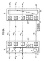
- FIG. 2 for example, two nodes of an MPLS network are shown, which are each designed as switching devices W, E.
- these switching devices are MPLS Cross Connect switching devices.
- other switching means such as e.g. ATM switches are also usable.
- MPLS packets Multiprotocol Label Switched Packets
- FIG. 2 MPLS packets (Multiprotocol Label Switched Packets) are now to be transmitted from the switching device configured as a label switched router W to the switching device designed as a label switched router E.
- FIG. 2a shows the transmission of MPLS packets from the label Switched Router W to the label Switched Router E, while in Fig. 2b the reverse direction of this connection is disclosed.
- FIGS. 2a and 2b together represent a bidirectional arrangement. By definition, however, connections for MPLS networks are in principle only defined unidirectionally. A bidirectional arrangement is achieved by logically associating two opposing unidirectional label switched paths (MPLS). It must be assumed here that the two opposing connections each connect the same switching devices (eg W and E in FIGS. 2a and 2b or also further intermediate switching devices). This is to be ensured when building the two connections.
- MPLS unidirectional label switched paths
- MPLS packets each have a header and an information part.
- the header is for receiving connection information while the information part of the recording of useful information is useful.
- payload IP packets are used.
- the connection information contained in the header is designed as an MPLS connection number. This is only valid in the MPLS network. Thus, if an IP packet from the Internet network IP penetrates into the MPLS network, this is appended to the valid in the MPLS network header. It contains all connection information that specifies the path of the MPLS packet in the MPLS network. If the MPLS packet leaves the MPLS network, the header is removed again and the IP packet in the subsequent Internet network IP is routed in accordance with the IP protocol.
- the label switched routers W, E are interconnected via operating links WE 1 ... WE n (WORKING ENTITY) and only one substitute link PE (PROTECTION ENTITY). Furthermore, switching devices S 0 ... S n (BRIDGE) are shown, via which the incoming MPLS packets and the assigned operating links WE 1 ... WE n are transmitted to the label switched router E. Furthermore, FIG. 2 shows selection devices SN whose task consists in supplying the MPLS packets transmitted via the operating links WE 1 ... WE n to the output of the label-switched router E. According to the present embodiment, the selection devices SN are designed as a coupling field. The switching network SN is arranged both in the label switched router W and in the label switched router E.
- E monitoring devices ÜE 0 ... ÜE n PROTECTION DOMAIN SINK, PROTECTION DOMAIN SOURCE
- the MPLS packets of the connection with the number 1 WT 1 before they are transmitted via the operating link WE 1 to the label switched router E are provided in the monitoring device UE 1 of the label switched router W with control information which the monitoring device UEE 1 of the receiving label switched router E takes and checks. Based on this control information can then be determined whether the transmission of the MPLS packet has been done correctly or not.
- a total failure (SIGNAL FAIL FOR WORKING ENTITY) of one of the operating distances WE 1 ... WE n can be determined here.
- deteriorations in the transmission quality can also be determined using known methods.
- the monitoring devices ÜE 1 ... ÜE n complete the operating distances WE 1 ... WE n on both sides. Further monitoring devices ÜE o are arranged on both ends of the substitute path PE. This is to serve in the event of an error as a transmission path for the decommissioned operating distance WE x . Furthermore, replacement switching protocols ES are transmitted via this, so that the integrity of the replacement link has the highest priority.
- each of the label switched routers W, E are also arranged central control devices ZST. These each contain priority tables PG, PL.
- the priority tables PL are local priority tables in which the state and priority of the local label switched router W are stored.
- the Priority Tables PG are global priority tables that maintain the state and priority of the local and the remaining Label Switched Routers E.
- the introduction of the priorities ensures that the simultaneous occurrence of multiple equivalent switch requests determines which operating link is to be replaced.
- the priority tables prioritize the equivalent switching requirements. For example, there is a high priority request from a user. Since this spare switching request is assigned a high priority, it is thus preferably controlled. An equivalent switching request controlled by one of the operating links, which is assigned a lower priority, is thus rejected.
- the individual priorities are shown in FIG.
- the central control devices ZST of the label switched routers W, E exchange information in an equivalent switching protocol ES.
- This protocol is transmitted via the substitute link PE and taken from the associated monitoring device ÜE 0 of the respective receiving label switched router, and supplied to the relevant central control device ZST. Furthermore, care is taken in the central control device ZST that, in the event of an error, the switching devices S 0 ... S n are controlled in a corresponding manner.
- Information K1, K2 is stored in the protocol ES.
- the former is information related to the generated replacement switch request, while the latter is information regarding the current states of the switching devices.
- the protocol ES is exchanged when generating an equivalent switching request between the two label switched routers W, E. In a special embodiment of the invention, it is provided to transmit the protocol ES cyclically between the two label switched routers W, E.
- FIG. 2 a shows the transmission of the MPLS packets from the label switched router W to the label switched router E via the operating links WE 1 ... WE n and FIG. 2 b is the associated opposite direction (bidirectional transmission). It is now initially assumed that the operating distances WE 1 ... WE n are still intact and correctly transmit the incoming MPLS packets.
- the MPLS packets belong to a plurality of connections WT 1 .. ..WT n .
- the individual connections are distinguished by the MPLS connection number entered in the packet header of the MPLS packets.
- the switching devices S 1 ... S n of the label switched router W are connected in this (still intact) operating case such that the MPLS packets to the monitoring means ÜE 1 ... ÜE n are supplied directly.
- the MPLS packets are supplied with the control information already mentioned and supplied to the monitoring device ÜE 1 ... UE n of the receiving label switched router E via the relevant operating link WE 1 ... WE n .
- the entrained control information is checked and possibly determined an error. If the transmission is correct, the MPLS packets are supplied to the switching network SN.
- the MPLS connection information is evaluated and forwarded in accordance with this evaluation, the MPLS packet on the candidate output of the switching network SN in the subsequent network.
- the spare distance PE can remain unused during this time.
- special data EXTRA TRAFFIC
- the switching device S 0 of the label switched router W assumes the position 2 in this case (FIG. 2 a).
- the transfer of the special data is also done in MPLS packages.
- the monitoring device ÜE 0 of the label switched router W acts on these special data leading MPLS packets in the same way with control information as has already been described in the case of the operating links WE 1 ... WE n .
- the replacement of the special data in the replacement switching case is not done by switching the switching device S 0 in Figure 2, but by prioritizing the high priority Traffic compared to the lower priority special data in each transmission facility.
- the operating distance WE 2 has failed. This is determined by the associated monitoring device UE 2 of the receiving label switched router E.
- the replacement switching request K1 is now transmitted to the respective central control device ZST and stored there in the local priority table PL and the global priority table PG.
- the equivalent circuit of this operating distance would be preferable to treat, since this operating distance is assigned a higher priority. In this case, a higher priority request is treated first.
- the priorities stored in the local and global priority table PL, PG are shown in FIG.
- the switching device S 2 of the label switched router E is controlled in the remaining operating state, as shown in Fig. 2b.
- the replacement switching protocol ES is now supplied to the label switched router W via the substitute link PE.
- the already mentioned information K1 and K2 are included. It is essential that the local priority logic defines the design of the information K1, and the global priority logic the position of the switching device S 0th
- the switching device S 2 is likewise activated and set in a corresponding manner. Furthermore, the switching device S 0 of the label switched router W is also allocated. The new status of the two switching devices S 0 , S 2 is the label Switched Router E acknowledged, and updated in the local priority table PG. The MPLS packets of the connection WT 2 are thus supplied to the label switched router E via the substitute link PE.
- the selection device SN of the receiving label switched router E is designed as a switching network.
- the MPLS packets routed via the substitute link PE are supplied to this switching network.
- the MPLS connection number ("label value") is taken from the packet header, evaluated and routed through the coupling field. The activation of switching devices is thus omitted in this case. Since these connections are a bidirectional connection, care must also be taken to transmit the MPLS packets in the reverse direction. This is done in accordance with FIG. 2b in the same way as has just been described for the transmission of the MPLS packets from the label switched router W to the label switched router E.
- FIG. 2b in the same way as has just been described for the transmission of the MPLS packets from the label switched router W to the label switched router E.
- the selection device is designed as a switching network, so that switching occurs in accordance with the MPLS connection number.
- the switching equipment of FIG. 3 are also - not shown - central Includes controllers with local and global priority tables.
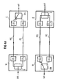
- FIG. 4 A further embodiment of the invention is shown in Fig. 4. It is a 1 + 1 structure.
- This structure results from the 1: n structure in that the switching devices S are fixed and can no longer be controlled by the central control devices ZST. In this way, the MPLS packets are also routed via the operating link WE as well as the substitute link PE during trouble-free operation.
- the selection device SN is not designed here as a switching network, but as a switching device.
- the replacement circuit protocol ES assumes a simpler form in this case.
- the information K2 describe here the state of the selection device. Whenever the switching devices S 0 ... S n have been controlled in the case of the 1: 1 structure, in the case of the 1 + 1 structure, the selection device SN is controlled instead.
- MPLS LSP Label Switched Path
- the operating and backup sections WE and PE must be set up before commissioning. For this purpose, connections between the label switched routers W and E, as well as, where appropriate, at intermediate transmission facilities must be set up (configured).
- TMN telecommunications network management
- MPLS MPLS signaling protocol
- the route of the operating or replacement route is determined by signaling.
- bandwidth is reserved in the transmission facilities via the signaling protocol in order to ensure transmission of the information over the service or spare line.
Landscapes
- Engineering & Computer Science (AREA)
- Computer Networks & Wireless Communication (AREA)
- Data Exchanges In Wide-Area Networks (AREA)
Abstract
Description
Die Erfindung betrifft ein Verfahren zum Ersatzschalten von Übertragungseinrichtungen in MPLS-Netzen gemäß dem Oberbegriff des Patentanspruchs 1.The invention relates to a method for replacement switching of transmission devices in MPLS networks according to the preamble of
Ein Verfahren zum Ersatzschalten von Übertragungseinrichtungen ist bereits aus der deutschen Patentschrift DE 196 46 016 C2 bekannt.A method for replacing switching transmission equipment is already known from German Patent DE 196 46 016 C2.
Dieses bekannte Verfahren bezieht sich auf Übertragungseinrichtungen, über die Informationen nach einem asynchronen Transfermodus (ATM) geleitet werden. Hierbei ist eine Übertragungseinrichtung zur bidirektionalen Übertragung von Digitalsignalen vorgesehen, bei der zwei als Endstellen fungierende Vermittlungseinrichtungen über eine Mehrzahl von Betriebsstrecken und eine Ersatzstrecke miteinander verbunden sind. Die beiden Endstellen enthalten jeweils eine Überwachungsvorrichtung zur Feststellung von Übertragungsstörungen. Eine durch die Überwachungsvorrichtung steuerbare Schaltvorrichtung verbindet eine Empfangsvorrichtung in einen ersten Schaltzustand mit der Betriebsstrecke und in einem zweiten Schaltzustand mit der Ersatzstrecke.This known method relates to transmission facilities over which information is passed in an asynchronous transfer mode (ATM). In this case, a transmission device is provided for the bidirectional transmission of digital signals, in which two switching devices functioning as terminals are connected to one another via a plurality of operating links and a substitute link. The two terminals each contain a monitoring device for detecting transmission interference. A controllable by the monitoring device switching device connects a receiving device in a first switching state with the operating distance and in a second switching state with the spare distance.
Nachteilig an diesem bekannten Verfahren ist, daß es sich ausschließlich auf ATM-Übertragungseinrichtungen bezieht. Im Internet werden Informationen über eine Mehrzahl von Netzknoten, die als Router ausgebildet sein können, dem empfangenden Teilnehmer zugeführt. Zwischen den Routern können MPLS-Netze angeordnet sein. MPLS-Netze sind aber in dem bekannten Verfahren nicht angesprochen.A disadvantage of this known method is that it relates exclusively to ATM transmission facilities. In the Internet, information about a plurality of network nodes, which may be configured as routers, is supplied to the receiving subscriber. Between the routers MPLS networks can be arranged. However, MPLS networks are not addressed in the known method.
Der Erfindung liegt die Aufgabe zugrunde, ein Verfahren der eingangs genannten Art derart weiterzubilden, daß auch im Internet Informationen mit großer Sicherheit über eine Mehrzahl von Netzknoten übertragen werden können.The invention has the object of providing a method of the type mentioned in such a way that even on the Internet Information can be transmitted with great certainty over a plurality of network nodes.
Die Erfindung wird ausgehend von den im Oberbegriff des Patentanspruchs 1 angegebenen Merkmale durch dessen kennzeichnende Merkmale gelöst.The invention is achieved on the basis of the features specified in the preamble of
Vorteilhaft an der Erfindung ist insbesondere, daß zwei gegenläufige unidirektionale MPLS-Verbindungen logisch miteinander derart assoziiert werden, daß die beiden gegenläufigen MPLS-Verbindungen jeweils die gleichen Vermittlungseinrichtungen verbinden. Somit kann sowohl eine bidirektionale Übertragung als auch eine 1:n unidirektionale Übertragung wofür auch ein Rückkanal benötigt wird) realisiert werden. Ferner wird lediglich eine Ersatzstrecke vorgesehen, die einer Mehrzahl von Betriebsstrecken zugeordnet ist. Über diese Ersatzstrecke werden die MPLS-Pakete der gestörten Betriebstrecke nach Maßgabe von Prioritätskriterien weitergeleitet. Die Durchschaltung durch die empfangende Vermittlungseinrichtung erfolgt dann unter zu Hilfenahme einer MPLS-Verbindungsnummer. Damit ist der Vorteil verbunden, daß die MPLS-Verbindung im Fehlerfall aufrechterhalten werden kann.An advantage of the invention is in particular that two opposing unidirectional MPLS connections are logically associated with each other such that the two opposing MPLS connections each connect the same switching equipment. Thus, both a bidirectional transmission and a 1: n unidirectional transmission for which a return channel is required) can be realized. Furthermore, only one spare section is provided, which is assigned to a plurality of operating sections. Via this replacement link, the MPLS packets of the faulty operating link are forwarded in accordance with priority criteria. The switching through the receiving switching device then takes place with the aid of an MPLS connection number. This has the advantage that the MPLS connection can be maintained in the event of a fault.
Verteilhafte Weiterbildungen der Erfindung sind in den Unteransprüchen anggegeben.Distributive developments of the invention are given in the dependent claims.
Die Erfindung wird im folgenden anhand eines Ausführungsbeispiels näher erläutert.The invention will be explained in more detail below with reference to an embodiment.
Es zeigen:
Figur 1- ein in das Internet eingebundenes MPLS-Netz,
Figur 2- das erfindungsgemäße Verfahren zur bidirektionalen Übertragung von MPLS-Paketen in einer 1:n-Struktur,
Figur 3- eine spezielle Ausgestaltung des erfindungsgemäßen Verfahrens in einer 1:1-Struktur,
Figur 4- eine weitere spezielle Ausgestaltung des erfindungsgemäßen Verfahrens in einer 1+1-Struktur.
- Figur 5
- die verwendeten Prioritäten, nach deren Maßgabe die Ersatzschaltung erfolgt.
- FIG. 1
- an Internet-based MPLS network,
- FIG. 2
- the method according to the invention for the bidirectional transmission of MPLS packets in a 1: n structure,
- FIG. 3
- a special embodiment of the method according to the invention in a 1: 1 structure,
- FIG. 4
- a further special embodiment of the method according to the invention in a 1 + 1 structure.
- FIG. 5
- the priorities used, according to which the equivalent circuit takes place.
In Fig. 1 ist beispielhaft aufgezeigt, wie Informationen ausgehend von einem Teilnehmer TLN1 einem Teilnehmer TLN2 zugeführt werden. Der sendende Teilnehmer TLN1 ist dabei an das Internet-Netz IP angeschlossen, durch das die Informationen nach einem Internetprotokoll wie z.B. das IP-Protokoll geleitet werden. Dieses Protokoll ist kein verbindungsorientiertes Protokoll. Das Internet-Netz IP weist eine Mehrzahl von Routern R auf, die untereinander vermascht sein können. Der empfangende Teilnehmer TLN2 ist an ein weiteres Internet-Netz IP angeschlossen. Zwischen den beiden Internet-Netzen IP ist ein MPLS-Netz (Multiprotocol Packet Label Switching) eingefügt, durch das Informationen in Form von MPLS-Paketen verbindungsorientiert durchgeschaltet werden. Dieses Netz weist eine Mehrzahl von miteinander vermaschten Routern auf. In einem MPLS-Netz können dies sogenannte Label Switched Router (LSR) sein. Einer der Router ist als sendende Einrichtung W und ein weiterer als empfangende Einrichtung E bezeichnet.FIG. 1 shows by way of example how information is supplied starting from a subscriber TLN1 to a subscriber TLN2. The sending subscriber TLN1 is connected to the Internet network IP, by which the information is sent to an internet protocol such as e.g. the IP protocol are routed. This protocol is not a connection-oriented protocol. The Internet network IP has a plurality of routers R, which can be meshed with each other. The receiving subscriber TLN2 is connected to another Internet network IP. Between the two Internet networks IP, an MPLS network (Multiprotocol Packet Label Switching) is inserted, through which information in the form of MPLS packets are switched connection-oriented. This network has a plurality of intermeshed routers. In an MPLS network, these may be so-called Label Switched Routers (LSR). One of the routers is designated as sending device W and another as receiving device E.
MPLS-Pakete weisen jeweils einen Kopfteil sowie einen Informationsteil auf. Der Kopfteil dient der Aufnahme von Verbindungsinformation während der Informationsteil der Aufnahme von Nutzinformation dienlich ist. Als Nutzinformation werden IP-Pakete verwendet. Die im Kopfteil enthaltene Verbindungsinformation ist als MPLS-Verbindungsnummer ausgebildet. Diese hat aber lediglich im MPLS-Netz Gültigkeit. Wenn somit ein IP-Paket vom Internet-Netz IP in das MPLS-Netz eindringt, wird diesem der im MPLS-Netz gültige Kopfteil angehängt. Darin sind alle Verbindungsinformationen enthalten, die den Weg des MPLS-Paketes im MPLS-Netz vorgeben. Verläßt das MPLS-Paket das MPLS-Netz, wird der Kopfteil wieder entfernt und das IP-Paket im sich daran anschließenden Internet-Netz IP nach Maßgabe des IP-Protokolls weitergeroutet.MPLS packets each have a header and an information part. The header is for receiving connection information while the information part of recording payload is useful. As payload IP packets are used. The connection information contained in the header is designed as an MPLS connection number. This is only valid in the MPLS network. Thus, if an IP packet from the Internet network IP penetrates into the MPLS network, this is appended to the valid in the MPLS network header. It contains all the connection information that shows the way of the MPLS packet in the MPLS network. If the MPLS packet leaves the MPLS network, the header is removed again and the IP packet in the subsequent Internet network IP is routed in accordance with the IP protocol.
In Fig. 2 sind beispielshaft zwei Knoten eines MPLS-Netzes aufgezeigt, welche jeweils als Vermittlungseinrichtung W, E ausgebildet sind. In vorliegendem Ausführungsbeispiel wird davon ausgegangen, daß es sich bei diesen Vermittlungseinrichtungen um MPLS Cross Connect Vermittlungseinrichtungen handelt. Die Verwendung derart ausgebildeter Vermittlungseinrichtungen bedeutet jedoch keine Einschränkung der Erfindung, andere Vermittlungseinrichtungen wie z.B. ATM-Vermittlungseinrichtungen sind ebenso verwendbar. In Fig. 2 sollen nun MPLS-Pakete (Multiprotocol Label Switched Packets) von der als Label Switched Router W ausgebildeten Vermittlungseinrichtung zu der als Label Switched Router E ausgebildeten Vermittlungseinrichtung hin übertragen werden.In FIG. 2, for example, two nodes of an MPLS network are shown, which are each designed as switching devices W, E. In the present embodiment, it is assumed that these switching devices are MPLS Cross Connect switching devices. However, the use of such switching devices does not imply any limitation of the invention, other switching means such as e.g. ATM switches are also usable. In FIG. 2 MPLS packets (Multiprotocol Label Switched Packets) are now to be transmitted from the switching device configured as a label switched router W to the switching device designed as a label switched router E.
In Fig. 2a ist die Übertragung von MPLS-Paketen von dem Label Switched Router W zu dem Label Switched Router E hin aufgezeigt, während in Fig. 2b die Rückrichtung dieser Verbindung offenbart ist. Die Figuren 2a und 2b stellen zusammen eine bidirektionale Anordnung dar. Definitionsgemäß sind jedoch für MPLS-Netze Verbindungen grundsätzlich nur unidirektional definiert. Eine bidirektionale Anordnung wird erreicht, indem zwei gegenläufige unidirektionale MPLS-Verbindungen (LSPs; label switched paths) logisch miteinander assoziert werden. Hierbei muß vorausgesetzt werden, daß die beiden gegenläufigen Verbindungen jeweils die gleichen Vermittlungseinrichtungen (z. B. W und E in Figur 2a und 2b oder auch weitere, dazwischen liegende Vermittlungseinrichtungen) verbinden. Dies ist beim Aufbau der beiden Verbindungen sicherzustellen.Fig. 2a shows the transmission of MPLS packets from the label Switched Router W to the label Switched Router E, while in Fig. 2b the reverse direction of this connection is disclosed. FIGS. 2a and 2b together represent a bidirectional arrangement. By definition, however, connections for MPLS networks are in principle only defined unidirectionally. A bidirectional arrangement is achieved by logically associating two opposing unidirectional label switched paths (MPLS). It must be assumed here that the two opposing connections each connect the same switching devices (eg W and E in FIGS. 2a and 2b or also further intermediate switching devices). This is to be ensured when building the two connections.
MPLS-Pakete weisen jeweils einen Kopfteil sowie einen Informationsteil auf. Der Kopfteil dient der Aufnahme von Verbindungsinformation während der Informationsteil der Aufnahme von Nutzinformation dienlich ist. Als Nutzinformation werden IP-Pakete verwendet. Die im Kopfteil enthaltene Verbindungsinformation ist als MPLS-Verbindungsnummer ausgebildet. Diese hat aber lediglich im MPLS-Netz Gültigkeit. Wenn somit ein IP-Packet vom Internet-Netz IP in das MPLS-Netz eindringt, wird diesem der im MPLS-Netz gültige Kopfteil angehängt. Darin sind alle Verbindungsinformationen enthalten, die den Weg des MPLS-Paketes im MPLS-Netz vorgeben. Verläßt das MPLS-Paket das MPLS-Netz, wird der Kopfteil wieder entfernt und das IP-Paket im sich daran anschließenden Internet-Netz IP nach Maßgabe des IP-Protokolls weitergeroutet.MPLS packets each have a header and an information part. The header is for receiving connection information while the information part of the recording of useful information is useful. As payload IP packets are used. The connection information contained in the header is designed as an MPLS connection number. This is only valid in the MPLS network. Thus, if an IP packet from the Internet network IP penetrates into the MPLS network, this is appended to the valid in the MPLS network header. It contains all connection information that specifies the path of the MPLS packet in the MPLS network. If the MPLS packet leaves the MPLS network, the header is removed again and the IP packet in the subsequent Internet network IP is routed in accordance with the IP protocol.
Die Label Switched Router W, E sind über Betriebsstrecken WE1...WEn (WORKING ENTITY) sowie lediglich eine Ersatzstrecke PE (PROTECTION ENTITY) miteinander verbunden. Weiterhin sind Schalteinrichtungen S0... Sn (BRIDGE) aufgezeigt, über die die ankommenden MPLS-Pakete und die zugeordneten Betriebsstrecken WE1 ... WEn zum Label Switched Router E hin übertragen werden. Weiterhin sind Fig. 2 Selektionseinrichtungen SN entnehmbar, deren Aufgabe darin besteht, die über die Betriebsstrecken WE1...WEn übertragenen MPLS-Pakete dem Ausgang des Label Switched Routers E zuzuführen. Gemäß vorliegendem Ausführungsbeispiel sind die Selektionseinrichtungen SN als Koppelfeld ausgebildet. Das Koppelfeld SN ist sowohl im Label Switched Router W als auch im Label Switched Router E angeordnet.The label switched routers W, E are interconnected via operating links WE 1 ... WE n (WORKING ENTITY) and only one substitute link PE (PROTECTION ENTITY). Furthermore, switching devices S 0 ... S n (BRIDGE) are shown, via which the incoming MPLS packets and the assigned operating links WE 1 ... WE n are transmitted to the label switched router E. Furthermore, FIG. 2 shows selection devices SN whose task consists in supplying the MPLS packets transmitted via the operating links WE 1 ... WE n to the output of the label-switched router E. According to the present embodiment, the selection devices SN are designed as a coupling field. The switching network SN is arranged both in the label switched router W and in the label switched router E.
Weiterhin sind in beiden Label Switched Router W, E Überwachungsvorrichtungen ÜE0...ÜEn (PROTECTION DOMAIN SINK, PROTECTION DOMAIN SOURCE) aufgezeigt, die den Zustand bzw. die Qualität der über die Betriebstrecken WE1...WEn übertragenen MPLS-Pakete überwachen. Beispielsweise werden die MPLS-Pakete der Verbindung mit der Nummer 1 WT1 bevor sie über die Betriebsstrecke WE1 zum Label Switched Router E hin übertragen werden, in der Überwachungseinrichtung ÜE1 des Label Switched Routers W mit Steuerinformation versehen, die die Überwachungseinrichtung ÜE1 des empfangenden Label Switched Routers E entnimmt und überprüft. Anhand dieser Steuerinformation kann dann ermittelt werden, ob die Übertragung des MPLS-Paketes korrekt erfolgt ist oder nicht. Insbesondere kann hier ein Totalausfall (SIGNAL FAIL FOR WORKING ENTITY) einer der Betriebsstrecken WE1...WEn ermittelt werden. Ebenso sind aber auch unter Verwendung bekannter Verfahren Verschlechterungen in der Übertragungsqualität (SIGNAL DEGRADE) ermittelbar.Furthermore, in both Label Switched Routers W, E monitoring devices ÜE 0 ... ÜE n (PROTECTION DOMAIN SINK, PROTECTION DOMAIN SOURCE) are shown that the state or the quality of over the operating links WE 1 ... WE n transmitted MPLS Monitor packets. By way of example, the MPLS packets of the connection with the
Die Überwachungsvorrichtungen ÜE1...ÜEn schließen die Betriebsstrecken WE1...WEn auf beiden Seiten ab. Weitere Überwachungsvorrichtungen ÜEo sind auf beiden Enden der Ersatzstrecke PE angeordnet. Diese soll im Fehlerfall als Übertragungsstrecke für die außer Betrieb genommene Betriebsstrecke WEx dienen. Weiterhin werden hierüber Ersatzschalteprotokolle ES übertragen, so daß die Intaktheit der Ersatzstrecke oberste Priorität hat.The monitoring devices ÜE 1 ... ÜE n complete the operating distances WE 1 ... WE n on both sides. Further monitoring devices ÜE o are arranged on both ends of the substitute path PE. This is to serve in the event of an error as a transmission path for the decommissioned operating distance WE x . Furthermore, replacement switching protocols ES are transmitted via this, so that the integrity of the replacement link has the highest priority.
In jeder der Label Switched Router W, E sind ferner zentrale Steuereinrichtungen ZST angeordnet. Diese beinhalten jeweils Prioritätstabellen PG, PL. Bei den Prioritätstabellen PL handelt es sich um lokale Prioritätstabellen, in denen Zustand und Priorität des lokalen Label Switched Routers W abgespeichert ist. Bei den Prioritätstabellen PG handelt es sich um globale Prioritätstabellen, die Zustand und Priorität des lokalen sowie des verbleibenden Label Switched Routers E führen. Durch die Einführung der Prioritäten wird erreicht, daß beim gleichzeitigen Auftreten mehrerer Ersatzschalteanforderungen festgelegt ist, welche Betriebstrecke ersatzzuschalten ist. Ebenso sind in den Prioritätstabellen die Ersatzschalteanforderungen priorisiert. So besteht beispielsweise eine hochpriore Anforderung von einem Anwender. Da dieser Ersatzschalteanforderung eine hohe Priorität zugewiesen ist, wird sie somit bevorzugt gesteuert. Eine von einer der Betriebsstrecken gesteuerte Ersatzschalteanforderung, der eine niedrigere Priorität zugewiesen ist, wird somit zurückgewiesen. Die einzelnen Prioritäten sind in Fig. 5 aufgezeigt.In each of the label switched routers W, E are also arranged central control devices ZST. These each contain priority tables PG, PL. The priority tables PL are local priority tables in which the state and priority of the local label switched router W are stored. The Priority Tables PG are global priority tables that maintain the state and priority of the local and the remaining Label Switched Routers E. The introduction of the priorities ensures that the simultaneous occurrence of multiple equivalent switch requests determines which operating link is to be replaced. Similarly, the priority tables prioritize the equivalent switching requirements. For example, there is a high priority request from a user. Since this spare switching request is assigned a high priority, it is thus preferably controlled. An equivalent switching request controlled by one of the operating links, which is assigned a lower priority, is thus rejected. The individual priorities are shown in FIG.
Die zentralen Steuereinrichtungen ZST der Label Switched Router W, E tauschen Informationen in einem Ersatzschalteprotokoll ES aus. Dieses Protokoll wird über die Ersatzstrecke PE übertragen und von der zugeordneten Überwachungseinrichtung ÜE0 des jeweils empfangenden Label Switched Routers entnommen, und der betreffenden zentralen Steuereinrichtung ZST zugeführt. Weiterhin wird in der zentralen Steuervorrichtung ZST dafür Sorge getragen, daß im Fehlerfall die Schaltvorrichtungen S0...Sn in entsprechender Weise gesteuert werden.The central control devices ZST of the label switched routers W, E exchange information in an equivalent switching protocol ES. This protocol is transmitted via the substitute link PE and taken from the associated monitoring device ÜE 0 of the respective receiving label switched router, and supplied to the relevant central control device ZST. Furthermore, care is taken in the central control device ZST that, in the event of an error, the switching devices S 0 ... S n are controlled in a corresponding manner.
Im Protokoll ES sind Informationen K1, K2 abgelegt. Bei ersteren handelt es sich um Informationen bezüglich der generierten Ersatzschalteanforderung, während es sich bei den letzteren um Informationen bezüglich der momentanen Zustände der Schalteinrichtungen handelt. Das Protokoll ES wird jeweils bei Generierung einer Ersatzschalteanforderung zwischen den beiden Label Switched Router W, E ausgetauscht. In einer speziellen Ausgestaltung der Erfindung wird vorgesehen, das Protokoll ES zyklisch zwischen beiden Label Switched Routern W, E zu übertragen.Information K1, K2 is stored in the protocol ES. The former is information related to the generated replacement switch request, while the latter is information regarding the current states of the switching devices. The protocol ES is exchanged when generating an equivalent switching request between the two label switched routers W, E. In a special embodiment of the invention, it is provided to transmit the protocol ES cyclically between the two label switched routers W, E.
Im folgenden wird nun die Durchführung des erfindungsgemäßen Verfahrens anhand Fig. 2 näher erläutert. Wie bereits erläutert zeigt Fig. 2a die Übertragung der MPLS-Pakete vom Label Switched Router W zum Label Switched Router E über die Betriebsstrecken WE1...WEn und Fig. 2b ist die zugehörige Gegenrichtung (bidirektionale Übertragung). Es wird nun zunächst davon ausgegangen, daß die Betriebstrecken WE1...WEn noch intakt sind und die ankommenden MPLS-Pakete korrekt übertragen.
Die MPLS-Pakete gehören einer Vielzahl von Verbindungen WT1.. ..WTn an. Die einzelnen Verbindungen werden anhand der im Paketkopf der MPLS-Pakete eingetragenen MPLS Verbindungsnummer unterschieden.In the following, the implementation of the method according to the invention will now be explained in more detail with reference to FIG. As already explained, FIG. 2 a shows the transmission of the MPLS packets from the label switched router W to the label switched router E via the operating links WE 1 ... WE n and FIG. 2 b is the associated opposite direction (bidirectional transmission). It is now initially assumed that the operating distances WE 1 ... WE n are still intact and correctly transmit the incoming MPLS packets.
The MPLS packets belong to a plurality of connections WT 1 .. ..WT n . The individual connections are distinguished by the MPLS connection number entered in the packet header of the MPLS packets.
Die Schalteinrichtungen S1...Sn des Label Switched Routers W sind in diesem (noch intakten) Betriebsfall derart geschaltet, daß die MPLS-Pakete den Überwachungseinrichtungen ÜE1... ÜEn unmittelbar zugeführt werden. In letzteren werden die MPLS-Pakete mit den bereits angesprochenen Steuerinformationen beaufschlagt und über die in Frage kommende Betriebsstrecke WE1...WEn den Überwachungseinrichtungen ÜE1... ÜEn des empfangenden Label Switched Routers E zugeführt. Dort wird die mitgeführte Steuerinformation überprüft und gegebenenfalls ein Fehlerfall ermittelt. Ist die Übertragung korrekt erfolgt, werden die MPLS-Pakete dem Koppelfeld SN zugeführt. Hier wird die MPLS Verbindungsinformation ausgewertet und nach Maßgabe dieser Auswertung das MPLS-Paket über dem in Frage kommenden Ausgang des Koppelfeldes SN in das sich anschließende Netz weitergeleitet.The switching devices S 1 ... S n of the label switched router W are connected in this (still intact) operating case such that the MPLS packets to the monitoring means ÜE 1 ... ÜE n are supplied directly. In the latter, the MPLS packets are supplied with the control information already mentioned and supplied to the monitoring device ÜE 1 ... UE n of the receiving label switched router E via the relevant operating link WE 1 ... WE n . There, the entrained control information is checked and possibly determined an error. If the transmission is correct, the MPLS packets are supplied to the switching network SN. Here, the MPLS connection information is evaluated and forwarded in accordance with this evaluation, the MPLS packet on the candidate output of the switching network SN in the subsequent network.
Die Ersatzstrecke PE kann während dieser Zeit ungenutzt bleiben. Gegebenenfalls können aber auch während dieser Zeit Sonderdaten (EXTRA TRAFFIC) dem Label Switched Router E zugeführt werden. Die Schaltvorrichtung S0 des Label Switched Routers W nimmt in diesem Fall die Stellung 2 ein (Fig. 2a). Die Übertragung der Sonderdaten erfolgt ebenfalls in MPLS-Paketen. Die Überwachungseinrichtung ÜE0 des Label Switched Routers W beaufschlagt diese Sonderdaten führenden MPLS-Pakete in gleicher Weise mit Steuerinformationen wie dies im Falle der über die Betriebsstrecken WE1...WEn bereits geschildert wurde.The spare distance PE can remain unused during this time. If necessary, special data (EXTRA TRAFFIC) can also be supplied to the Label Switched Router E during this time. The switching device S 0 of the label switched router W assumes the
Als Sonderdaten kann über die Ersatzstrecke auch niederpriorer Verkehr übertragen werden, der nur dann im Netz übertragen wird, wenn ausreichend Ressourcen vorhanden sind. Der niederpriore Verkehr wird dann in diesem Fall durch Ersatzschalten des hochprioren Verkehrs automatisch verdrängt. In diesem Fall erfolgt die Verdrängung der Sonderdaten im Ersatzschaltefall nicht durch Umschalten der Schaltvorrichtung S0 in Figur 2, sondern durch Priorisierung des hochprioren Verkehrs gegenüber den niederprioren Sonderdaten in jeder Übertragungseinrichtung.As special data, it is also possible to transmit low-priority traffic via the substitute route, which is only transmitted in the network if sufficient resources are available. The low-priority traffic is then automatically replaced in this case by replacing the high-priority traffic. In this case, the replacement of the special data in the replacement switching case is not done by switching the switching device S 0 in Figure 2, but by prioritizing the high priority Traffic compared to the lower priority special data in each transmission facility.
Im folgenden wird nun davon ausgegangen, daß die Betriebsstrecke WE2 ausgefallen ist. Dies wird von der dieser zugeordneten Überwachungseinrichtung ÜE2 des empfangenden Label Switched Routers E ermittelt. Die Ersatzschalteanforderung K1 wird nun zur betreffenden zentralen Steuereinrichtung ZST übermittelt und dort in der lokalen Prioritätstabelle PL sowie der globalen Prioritätstabelle PG abgelegt. Nach Maßgabe der in der globalen Prioritätstabelle PG abgespeicherten Prioritäten wird nun ermittelt, ob noch höher priore Anforderungen anstehen. Dies könnte beispielsweise die bereits angesprochene Umschalteanforderung des Anwenders (FORCED SWITCH FOR WORKING ENTITY) sein. Auch bei gleichzeitigem Auftreten anderer Störungsfalle wie beispielsweise der Betriebsstrecke WE1 wäre die Ersatzschaltung dieser Betriebsstrecke bevorzugt zu behandeln, da dieser Betriebsstrecke eine höhere Prioität zugewiesen ist. In diesem Fall wird eine höher priorisierte Anforderung zuerst behandelt. Die in der lokalen und globalen Prioritätstabelle PL, PG gespeicherten Prioritäten sind in Fig. 5 aufgezeigt.In the following it is now assumed that the operating distance WE 2 has failed. This is determined by the associated monitoring device UE 2 of the receiving label switched router E. The replacement switching request K1 is now transmitted to the respective central control device ZST and stored there in the local priority table PL and the global priority table PG. In accordance with the priorities stored in the global priority table PG, it is now determined whether even more stringent requirements are pending. This could be, for example, the already-mentioned user switching request (FORCED SWITCH FOR WORKING ENTITY). Even with simultaneous occurrence of other failure cases such as the operating distance WE 1 , the equivalent circuit of this operating distance would be preferable to treat, since this operating distance is assigned a higher priority. In this case, a higher priority request is treated first. The priorities stored in the local and global priority table PL, PG are shown in FIG.
Sind keine höher priorisierte Anforderungen vorhanden, wird die Schaltvorrichtung S2 des Label Switched Routers E in den verbleibenden Betriebszustand gesteuert, wie in Fig. 2b aufgezeigt. Im folgenden wird nun das Ersatzschalteprotokoll ES uber die Ersatzstrecke PE dem Label Switched Router W zugeführt. In diesem Ersatzschalteprotokoll sind die bereits angesprochenen Informationen K1 und K2 enthalten. Wesentlich ist, daß die lokale Prioritätslogik die Ausgestaltung der Information K1 definiert, und die globale Prioritätslogik die Stellung der Schaltvorrichtung S0.If no higher priority requirements are present, the switching device S 2 of the label switched router E is controlled in the remaining operating state, as shown in Fig. 2b. In the following, the replacement switching protocol ES is now supplied to the label switched router W via the substitute link PE. In this Ersatzschalteprotokoll the already mentioned information K1 and K2 are included. It is essential that the local priority logic defines the design of the information K1, and the global priority logic the position of the switching device S 0th
Von der Überwachungseinrichtung ÜE0 des Label Switched Routers W wird nun das Ersatzschalteprotokoll ES übernommen und der hier angeordneten zentralen Steuereinrichtung ZST zugeführt. Liegen auch hier in der globalen Prioritätstabelle PG keine weiteren höherpriorisierten Anforderungen an, so wird auch hier die Schaltvorrichtung S2 in entsprechender Weise angesteuert und eingestellt. Weiterhin wird die Schaltvorrichtung S0 des Label Switched Routers W ebenfalls umgelegt. Der neue Status der beiden Schaltvorrichtungen S0, S2 wird dem Label Switched Router E quittiert, und in der dortigen globalen Prioritätstabelle PG aktualisiert. Die MPLS-Pakete der Verbindung WT2 werden somit über die Ersatzstrecke PE dem Label Switched Router E zugeführt.From the monitoring device ÜE 0 of the label switched router W now the Ersatzschalteprotokoll ES is taken over and supplied to the central control device arranged here ZST. If there are no further prioritized requirements here in the global priority table PG, the switching device S 2 is likewise activated and set in a corresponding manner. Furthermore, the switching device S 0 of the label switched router W is also allocated. The new status of the two switching devices S 0 , S 2 is the label Switched Router E acknowledged, and updated in the local priority table PG. The MPLS packets of the connection WT 2 are thus supplied to the label switched router E via the substitute link PE.
Die Selektionseinrichtung SN des empfangenden Label Switched Routers E ist als Koppelfeld ausgebildet. Die über die Ersatzstrecke PE geleiteten MPLS-Pakete werden diesem Koppelfeld zugeführt. Hier wird nun die MPLS-Verbindungsnummer ("Label value") dem Paketkopf entnommen, ausgewertet und durch das Koppelfeld durchgeroutet. Das Ansteuern von Schalteinrichtungen entfällt somit in diesem Fall. Da es sich bei diesen Verbindungen um eine bidirektionale Verbindung handelt, muß auch für die Übertragung der MPLS-Pakete der Rückwärtsrichtung Sorge getragen werden. Dies erfolgt gemäß Fig. 2b in gleicher Weise, wie soeben für die Übertragung der MPLS-Pakete von dem Label Switched Router W zum Label Switched Router E hin geschildert wurde.The selection device SN of the receiving label switched router E is designed as a switching network. The MPLS packets routed via the substitute link PE are supplied to this switching network. Here, the MPLS connection number ("label value") is taken from the packet header, evaluated and routed through the coupling field. The activation of switching devices is thus omitted in this case. Since these connections are a bidirectional connection, care must also be taken to transmit the MPLS packets in the reverse direction. This is done in accordance with FIG. 2b in the same way as has just been described for the transmission of the MPLS packets from the label switched router W to the label switched router E. FIG.
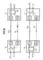
Gemäß dem soeben beschriebenen Ausführungsbeispiel wurde von einer 1:n Struktur ausgegangen. Dies bedeutet, daß für n Betriebsstrecken lediglich eine Ersatzstrecke zur Verfügung steht. Ein Spezialfall ist also dann gegeben, wenn n=1 gilt. In diesem Fall wird also eine 1:1 Struktur verwendet. Die entsprechenden Verhältnisse sind in Fig. 3 aufgezeigt.According to the embodiment just described, a 1: n structure was assumed. This means that only one spare line is available for n operating links. A special case is given if n = 1. In this case, a 1: 1 structure is used. The corresponding ratios are shown in Fig. 3.
Auch in diesem Fall ist die Selektionseinrichtung als Koppelfeld ausgebildet, so daß ein Durchschalten nach Maßgabe der MPLS-Verbindungsnummer erfolgt. In den Vermittlungseinrichtungen gemäß Fig. 3 sind ebenso - nicht aufgezeigte - zentrale Steuereinrichtungen mit lokalen und globalen Prioritätstabellen enthalten.Also in this case, the selection device is designed as a switching network, so that switching occurs in accordance with the MPLS connection number. In the switching equipment of FIG. 3 are also - not shown - central Includes controllers with local and global priority tables.
Eine weitere Ausgestaltung der Erfindung ist in Fig. 4 aufgezeigt. Dabei handelt es sich um eine 1+1 Struktur. Diese Struktur ergibt sich aus der 1:n Struktur, indem die Schaltvorrichtungen S fest eingestellt werden und nicht mehr über die zentralen Steuervorrichtungen ZST steuerbar sind. Damit werden die MPLS-Pakete auch im störungsfreien Betriebsfall sowohl über die Betriebsstrecke WE als auch die Ersatzstrecke PE geleitet. Die Selektionseinrichtung SN ist hier nicht als Koppelfeld ausgebildet, sondern als Schaltvorrichtung. Das Ersatzschalteprotokoll ES nimmt in diesem Fall eine einfachere Form an. Die Informationen K2 beschreiben hier den Zustand der Selektionsvorrichtung. Immer dann, wenn im Falle der 1:n Struktur die Schaltvorrichtungen S0...Sn gesteuert wurden, wird im Falle der 1+1 Strukur stattdessen die Selektionsvorrichtung SN gesteuert.A further embodiment of the invention is shown in Fig. 4. It is a 1 + 1 structure. This structure results from the 1: n structure in that the switching devices S are fixed and can no longer be controlled by the central control devices ZST. In this way, the MPLS packets are also routed via the operating link WE as well as the substitute link PE during trouble-free operation. The selection device SN is not designed here as a switching network, but as a switching device. The replacement circuit protocol ES assumes a simpler form in this case. The information K2 describe here the state of the selection device. Whenever the switching devices S 0 ... S n have been controlled in the case of the 1: 1 structure, in the case of the 1 + 1 structure, the selection device SN is controlled instead.
Alle bisher beschriebenen Ausgestaltungen der Erfindung sind bidirektional, in dem Sinne, dass sowohl Nutzdaten als auch Protokollkommunikation in beiden Richtungen stattfindet. In einer weiteren Ausgestaltung der Erfindung ist ein 1:n unidirektionaler Betrieb möglich. Hierbei werden Nutzdaten nur in einer Richtung übertragen (z. B. gemäß der Anordnung in Fig. 2a). In der Rückrichtung (vgl. Figur 2b) werden keine Nutzdaten übertragen. Allerdings muß in der Rückrichtung weiterhin die Ersatzstrecke (PE in Figur 2b) vorhanden sein, da die Protokollkommunikation (wie im bidirektionalen Fall) weiterhin benötigt wird, damit die Schaltvorrichtungen So bis Sn in Fig. 2a gesteuert werden können.All embodiments of the invention described so far are bidirectional, in the sense that both user data and protocol communication takes place in both directions. In a further embodiment of the invention, a 1: n unidirectional operation is possible. In this case, user data are transmitted only in one direction (eg according to the arrangement in FIG. In the return direction (see Figure 2b) no user data are transmitted. However, the backup path (PE in FIG. 2 b) must continue to be present in the return direction since the protocol communication (as in the bidirectional case) is still required so that the switching devices S 0 to S n in FIG. 2 a can be controlled.
Ein Spezialfall der unidirektionalen 1:n Struktur ist gegeben, wenn n=1 gilt (siehe hierzu Figur 3).A special case of the unidirectional 1: n structure is given if n = 1 (see FIG. 3).
Bislang wurde davon ausgegangen, daß jede MPLS-Verbindung individuell überwacht und ersatzgeschaltet wird. Ausfälle und Störungen können daher verbindungsindividuell derart berücksichtigt werden, indem bei Ausfall oder Verschlechterung der Übertragungsqualität einer einzelnen Verbindung diese ersatzgeschaltet werden kann.Previously, it was assumed that each MPLS connection was individually monitored and replaced. Failures and Disruptions can therefore be taken into account individually in such a way that, in the event of a breakdown or deterioration of the transmission quality of a single connection, this can be switched over.
In praktischen Ausführungen von Übertragungseinrichtungen dieser Art werden jedoch häufig viele Einzelverbindungen über den gleichen physikalischen Weg (z. B. eine Glasfaser) zwischen Übertragungseinrichtungen geführt. Im Falle einer Unterbrechung dieses Weges (z. B. Glasfaserbruch) sind dann alle Einzelverbindungen durch einen einzigen Ausfall betroffen. Ausfälle dieser Art überwiegen in der Praxis gegenüber Ausfällen, die nur Einzelverbindungen betreffen. Insbesondere müßten in diesem Fall für jede unterbrochene Einzelverbindung ein Ersatzschalteprotokoll in der Prioritätstabelle PL eingetragen werden.In practical embodiments of transmission devices of this type, however, many individual connections are often routed via the same physical path (eg a glass fiber) between transmission devices. In the case of an interruption of this path (eg glass fiber breakage) all individual connections are then affected by a single failure. Failures of this kind predominate in practice over failures that affect only individual connections. In particular, in this case, a replacement switching protocol would have to be entered in the priority table PL for each interrupted individual connection.
In einer Ausgestaltung der Erfindung wird daher vorgesehen, mittels einer Gruppenersatzschaltung eine Vielzahl von Einzelverbindungen gemeinsam ersatzzuschalten.In one embodiment of the invention, it is therefore provided to replace a plurality of individual connections together by means of a group substitute circuit.
Hierzu werden alle über denselben physikalischen Pfad geführten MPLS-Verbindungen logisch zu einer Gruppe zusammengefaßt. Ferner werden für diese Gruppe 2 Ersatzschalteverbindungen erstellt. Die erste dieser Ersatzschalteverbindungen wird über die Betriebsstrecke WE geleitet (MPLS-Ersatzschalte-LSP; LSP= Label Switched Path), womit sie über den gleichen physikalischen Weg zwischen den Label Switched Routern W und E geführt ist, wie alle zugehörigen Einzelverbindungen.Die zweite dieser Ersatzschalteverbindungen wird über die Ersatzstrecke PE eingerichtet.For this purpose, all MPLS connections routed via the same physical path are logically combined to form a group. Furthermore, 2 spare circuit connections are made for this group. The first of these spare switching connections is routed over the operating link WE (MPLS LSP = Label Switched Path), which leads it via the same physical path between the label switched routers W and E as all the associated individual connections. The second of these Spare switching connections is established via the substitute route PE.
Im Gruppenersatzschalteverfahren werden nun nur noch diese beiden Ersatzschalteverbindungen auf Ausfälle und Störungen in den Überwachungseinrichtungen ÜE1, ÜE0 überwacht. Die Einzelverbindungen werden nicht mehr überwacht. Im Falle einer Ersatzschalteanforderung wird die prioritätsgesteuerte Ersatzschalteentscheidung wie bisher in der Prioritätslogik PL getroffen. Im Ersatzschaltefall werden allerdings alle zu einer Gruppe zugehörigen Einzelverbindungen gemeinsam durch die Schaltvorrichtung SN umgeschaltet. Dabei muß nur ein einziges Ersatzschalteprotokoll über die Ersatzstrecke PE abgewickelt werden.In the group replacement switching method, only these two equivalent switching connections will now be monitored for failures and malfunctions in the monitoring devices ÜE 1 , ÜE 0 . The individual connections are no longer monitored. In the case of a replacement switch request, the priority-driven backup decision becomes as previously hit in the priority logic PL. In the equivalent circuit case, however, all the individual connections belonging to a group are switched together by the switching device SN. In this case, only a single Ersatzschalteprotokoll must be handled on the replacement line PE.
Vorteilhaft daran ist, daß eine Vielzahl von Einzelverbindungen durch eine einzige Ersatzschalteverbindung und ein einziges Ersatzschalteprotokoll überwacht und ersatzgeschalret werden können, um somit auf die im praktischen Betrieb am häufigsten vorkommenden Fehlerfälle angemessen reagieren zu können. Ferner wird lediglich ein Ersatzschalteprotokoll in der Prioritätstabelle PL eingetragen.The advantage of this is that a plurality of individual connections can be monitored and replaced by a single equivalent circuit connection and a single circuit breaker protocol so as to be able to adequately respond to the most frequently occurring error cases in practical operation. Furthermore, only one spare switching protocol is entered in the priority table PL.
Die Betriebs- und Ersatzstrecken WE und PE müssen vor Inbetriebnahme eingerichtet werden. Dazu müssen Verbindungen zwischen den Label Switched Routern W und E, sowie gegebenenfalls an dazwischenliegenden Übertragungseinrichtungen eingerichtet (konfiguriert) werden.The operating and backup sections WE and PE must be set up before commissioning. For this purpose, connections between the label switched routers W and E, as well as, where appropriate, at intermediate transmission facilities must be set up (configured).
Das Einrichten dieser Verbindungen erfolgt üblicherweise per TMN (Telekommunikations-Netzmanagement), kann aber auch mittels eines MPLS-Signalisierungsprotokolles erfolgen. Hierzu wird dabei per Signalisierung der Weg der Betriebs- bzw. Ersatzstrecke festgelegt. Zusätzlich wird über das Signalisierungsprotokoll Bandbreite in den Übertragungseinrichtungen reserviert, damit die Übertragung der Informationen über die Betriebs- bzw. Ersatzstrecke sichergestellt ist.The establishment of these connections is usually carried out by TMN (telecommunications network management), but can also be done by means of an MPLS signaling protocol. For this purpose, the route of the operating or replacement route is determined by signaling. In addition, bandwidth is reserved in the transmission facilities via the signaling protocol in order to ensure transmission of the information over the service or spare line.
Claims (16)
- Method for the protection switching of transmission devices for transmitting MPLS packets, comprising
a transmitting and a receiving switching system (W, E) between which further switching systems can be arranged, and which terminate a transmission section formed from a multiplicity of operating links (WE1...WEn) and which exchange information over the multiplicity of operating links (WE1...WEn), and with monitoring devices (ÜE1... ÜEn) which are in each case arranged at the end of an operating link and by which a disturbance of the operating link is determined, in which arrangement a protection link (PE) is additionally provided between the two switching systems (W, E) via which, in the case of a disturbance on one of the operating links, the information transmitted via it is forwarded as determined by priority criteria by means of which, in the case of a simultaneous occurrence of a number of protection switching requests, it is defined which operating link is to be protection switched, and by connection information imparted by the information, characterized in that the information is linked into MPLS packets, in that two oppositely directed unidirectional MPLS connections are logically associated with one another, the two oppositely directed MPLS connections in each case connecting the same switching systems. - Method according to Claim 1, characterized in that a priority is allocated to the operating links (WE1...WEn) and to the protection link (PE).
- Method according to Claim 1 or 2, characterized in that in the protection switching case, a protection switching request (K1) is generated to which other priorities are assigned.
- Method according to Claim 1, characterized in that the logical connection information is the MPLS connection number (Label Value).
- Method according to Claim 1 to 4, characterized in that priority tables (PL, PG) are provided in which the priorities are defined.
- Method according to one of Claims 1 to 5, characterized in that the protection switching is effected by driving a switching system (S0 ...Sn) contained in the transmitting switching system and by using a selection device (SN) arranged in the receiving switching system.
- Method according to Claim 6, characterized in that the selection device (SN) is constructed as a switching network.
- Method according to one of the preceding claims, characterized in that group protection switching is provided in that all MPLS connections conducted via the same physical path are logically combined to form a group, and for the group formed in this manner at least two protection switching connections are generated, in each case one of these protection switching connections being set up via an operating link (WE) and another one of these protection switching connections being set up via the protection link (PE).
- Method according to Claim 8, characterized in that, in the case where group protection switching is provided, the monitoring devices (UE0...UEn) only monitor the at least two protection switching connections.
- Method according to one of the preceding claims, characterized in that the connections conducted via the at least one operating link (WE) and the connections conducted via the protection link (PE) are set up via an MPLS signalling protocol which also reserves bandwidth in the transmission devices and specifies the path of the operating link(s) (WE) and of the protection link (PE).
- Method according to one of the preceding claims, characterized in that special data are transmitted via the protection link (PE) in times free of operating disturbances.
- Method according to Claim 11, characterized in that the special data are arranged as low-priority traffic which is automatically displaced in the case of protection switching of the high-priority traffic.
- Method according to one of the preceding claims, characterized in that when a protection switching request arrives in the receiving switching system, a protection switching protocol (ES) is generated which is supplied only once to the remaining switching system via the protection link (PE).
- Method according to one of the preceding claims, characterized in that total failure and degradation of an operating link are determined in the monitoring device of the receiving switching system.
- Method according to one of the preceding claims, characterized in that the switching system can be permanently set.
- Method according to one of the preceding claims, characterized in that the switching systems are constructed as cross-connect switching systems.
Priority Applications (1)
| Application Number | Priority Date | Filing Date | Title |
|---|---|---|---|
| EP01902311A EP1262084B1 (en) | 2000-02-15 | 2001-01-12 | Equivalent switching method for transmission devices in mpls networks |
Applications Claiming Priority (4)
| Application Number | Priority Date | Filing Date | Title |
|---|---|---|---|
| EP00103083 | 2000-02-15 | ||
| EP00103083A EP1126742A1 (en) | 2000-02-15 | 2000-02-15 | Method for protection switching of transmission equipment in MPLS networks |
| PCT/EP2001/000337 WO2001062036A1 (en) | 2000-02-15 | 2001-01-12 | Equivalent switching method for transmission devices in mpls networks |
| EP01902311A EP1262084B1 (en) | 2000-02-15 | 2001-01-12 | Equivalent switching method for transmission devices in mpls networks |
Publications (2)
| Publication Number | Publication Date |
|---|---|
| EP1262084A1 EP1262084A1 (en) | 2002-12-04 |
| EP1262084B1 true EP1262084B1 (en) | 2006-08-02 |
Family
ID=8167860
Family Applications (2)
| Application Number | Title | Priority Date | Filing Date |
|---|---|---|---|
| EP00103083A Withdrawn EP1126742A1 (en) | 2000-02-15 | 2000-02-15 | Method for protection switching of transmission equipment in MPLS networks |
| EP01902311A Expired - Lifetime EP1262084B1 (en) | 2000-02-15 | 2001-01-12 | Equivalent switching method for transmission devices in mpls networks |
Family Applications Before (1)
| Application Number | Title | Priority Date | Filing Date |
|---|---|---|---|
| EP00103083A Withdrawn EP1126742A1 (en) | 2000-02-15 | 2000-02-15 | Method for protection switching of transmission equipment in MPLS networks |
Country Status (7)
| Country | Link |
|---|---|
| US (2) | US20030065815A1 (en) |
| EP (2) | EP1126742A1 (en) |
| CN (1) | CN1180654C (en) |
| AU (1) | AU768710B2 (en) |
| CA (1) | CA2400219A1 (en) |
| DE (1) | DE50110616D1 (en) |
| WO (1) | WO2001062036A1 (en) |
Families Citing this family (13)
| Publication number | Priority date | Publication date | Assignee | Title |
|---|---|---|---|---|
| JP4548930B2 (en) * | 2000-11-15 | 2010-09-22 | 富士通株式会社 | Label switching router |
| WO2003096631A1 (en) * | 2002-05-08 | 2003-11-20 | Siemens Aktiengesellschaft | Method for assisting equivalent circuits in mpls networks |
| US8554947B1 (en) * | 2003-09-15 | 2013-10-08 | Verizon Laboratories Inc. | Network data transmission systems and methods |
| US7174427B2 (en) | 2003-12-05 | 2007-02-06 | Intel Corporation | Device and method for handling MPLS labels |
| AU2010201307B2 (en) * | 2004-04-16 | 2013-05-16 | Dolby Laboratories Licensing Corporation | Devices and methods for routeing a unit of data in a network |
| KR101155386B1 (en) * | 2004-04-16 | 2012-06-21 | 스마트 인터넷 테크놀로지 씨알씨 피티와이 엘티디 | Devices and methods for routing a unit of data in a network |
| AU2005234094B2 (en) * | 2004-04-16 | 2010-05-20 | Dolby Laboratories Licensing Corporation | Devices and methods for routeing a unit of data in a network |
| ES2314777T3 (en) | 2006-05-04 | 2009-03-16 | NOKIA SIEMENS NETWORKS GMBH & CO. KG | AUTOMATIC PROTECTION OF PACK TRANSMISSION IN A MPLS NETWORK BY THE ETHERNET DUAL-HOME BRIDGE. |
| US8309528B2 (en) * | 2006-05-10 | 2012-11-13 | The Trustees Of Columbia University In The City Of New York | Two pore channels as regulators of proliferation in cancer |
| ITTO20060364A1 (en) * | 2006-05-19 | 2007-11-20 | Xanto Technologies Srl | USB MASS MEMORY DEVICE AND ITS DATA TRANSFER PROCEDURE |
| CN102170392A (en) * | 2010-02-26 | 2011-08-31 | 中兴通讯股份有限公司 | Method and system for establishing associated double-way label switching path |
| US8477598B2 (en) * | 2010-08-03 | 2013-07-02 | Fujitsu Limited | Method and system for implementing network element-level redundancy |
| US9806939B2 (en) * | 2013-10-17 | 2017-10-31 | Electronics And Telecommunications Research Institute | Method and apparatus for linear protection switching |
Family Cites Families (12)
| Publication number | Priority date | Publication date | Assignee | Title |
|---|---|---|---|---|
| US5479608A (en) * | 1992-07-17 | 1995-12-26 | Alcatel Network Systems, Inc. | Group facility protection in a digital telecommunications system |
| WO1994028646A1 (en) * | 1993-05-28 | 1994-12-08 | Siemens Aktiengesellschaft | Equivalent circuit process for a transmission device for the bidirectional transmission of digital signals and arrangement for implementing the process |
| JP3439533B2 (en) * | 1994-06-24 | 2003-08-25 | 富士通株式会社 | SDH2-fiber ring optical multiplexer having selective protection function |
| CN1198423C (en) * | 1996-04-23 | 2005-04-20 | 株式会社日立制作所 | Self-healing network, method for transmission line switching thereof, and transmission equipment thereof |
| US5838924A (en) * | 1996-08-06 | 1998-11-17 | Lucent Technologies Inc | Asynchronous transfer mode (ATM) connection protection switching apparatus and method |
| DE19646016C2 (en) * | 1996-11-07 | 1999-10-14 | Siemens Ag | Method for the equivalent switching of transmission devices for the bidirectional transmission of ATM cells |
| US6535481B1 (en) * | 1999-08-20 | 2003-03-18 | Nortel Networks Limited | Network data routing protection cycles for automatic protection switching |
| US6532088B1 (en) * | 1999-09-10 | 2003-03-11 | Alcatel | System and method for packet level distributed routing in fiber optic rings |
| US6628649B1 (en) * | 1999-10-29 | 2003-09-30 | Cisco Technology, Inc. | Apparatus and methods providing redundant routing in a switched network device |
| CA2310872A1 (en) * | 1999-12-22 | 2001-06-22 | Nortel Networks Corporation | Automatic protection switching using link-level redundancy supporting multi-protocol label switching |
| EP1130853A1 (en) * | 2000-02-29 | 2001-09-05 | Siemens Aktiengesellschaft | Circuit arrangement for changeover to standby of transmission installations in ring architectures with MPLS-packets |
| US6775229B1 (en) * | 2000-05-05 | 2004-08-10 | Fujitsu Network Communications, Inc. | Method and system for providing a protection path for connection-oriented signals in a telecommunications network |
-
2000
- 2000-02-15 EP EP00103083A patent/EP1126742A1/en not_active Withdrawn
-
2001
- 2001-01-12 DE DE50110616T patent/DE50110616D1/en not_active Expired - Fee Related
- 2001-01-12 US US10/203,980 patent/US20030065815A1/en not_active Abandoned
- 2001-01-12 EP EP01902311A patent/EP1262084B1/en not_active Expired - Lifetime
- 2001-01-12 CN CNB018050778A patent/CN1180654C/en not_active Expired - Fee Related
- 2001-01-12 WO PCT/EP2001/000337 patent/WO2001062036A1/en active IP Right Grant
- 2001-01-12 AU AU30181/01A patent/AU768710B2/en not_active Ceased
- 2001-01-12 CA CA002400219A patent/CA2400219A1/en not_active Abandoned
-
2008
- 2008-08-28 US US12/135,815 patent/US20080310429A1/en not_active Abandoned
Also Published As
| Publication number | Publication date |
|---|---|
| EP1126742A1 (en) | 2001-08-22 |
| CN1180654C (en) | 2004-12-15 |
| CN1401201A (en) | 2003-03-05 |
| DE50110616D1 (en) | 2006-09-14 |
| AU768710B2 (en) | 2004-01-08 |
| US20080310429A1 (en) | 2008-12-18 |
| WO2001062036A1 (en) | 2001-08-23 |
| AU3018101A (en) | 2001-08-27 |
| EP1262084A1 (en) | 2002-12-04 |
| US20030065815A1 (en) | 2003-04-03 |
| CA2400219A1 (en) | 2001-08-23 |
Similar Documents
| Publication | Publication Date | Title |
|---|---|---|
| DE19532422C1 (en) | Local network operating according to the asynchronous transfer mode (ATM) with at least two ring systems | |
| EP1262084B1 (en) | Equivalent switching method for transmission devices in mpls networks | |
| EP1130853A1 (en) | Circuit arrangement for changeover to standby of transmission installations in ring architectures with MPLS-packets | |
| EP0937370B1 (en) | Switching transmission units to an equivalent circuit for the purposes of bidirectional asynchronous cell transfer | |
| DE10219153A1 (en) | Procedure for checking the continuity of connections in MPLS networks | |
| EP0845879B1 (en) | Optical switching unit, particularly for switching to alternative components in optical transmission systems | |
| EP1410576B1 (en) | Method for providing an equivalent circuit for transmission devices in ring architectures that route mpls packets | |
| EP0385127A2 (en) | Communication network with switchable network nodes | |
| EP0857002A2 (en) | Apparatus for realising redundancy circuits of telecommunication devices in ring architectures for the bidirectional transmission of ATM cells | |
| EP1097540B1 (en) | Method and device for optimising the transmission safety and the defect tolerance in high-bit-rate data networks | |
| DE10142372B4 (en) | Device and method for restoring connections in automatically switchable optical networks | |
| WO2003081850A1 (en) | Method for operation and monitoring of mpls networks | |
| EP1313347A1 (en) | Routing in transport networks | |
| EP0645911A2 (en) | Hierachical communication network | |
| EP1126741A1 (en) | Method for protection switching of transmission equipment in MPLS networks | |
| EP0978217B1 (en) | Method for changeover to standby of transmission installations for bi-directional transmission of atm cells | |
| EP0868103A2 (en) | Acceptance of connections with lower priority, in particular of non-real-time (NRT) traffic, only by redundant transmission paths | |
| EP0857003A2 (en) | Apparatus for realising redundancy circuits of communication devices in ring architectures for the bidirectional transmission of ATM cells | |
| EP0984658B1 (en) | Telecommunication system with switching device and data concentrator for access to Internet | |
| DE10152339B4 (en) | Method and communication device for implementing at least one fail-safe communication relationship by a communication device arranged in a communication network | |
| DE10324604A1 (en) | Method for forwarding IP packets to an external control component of a network node in a communication network which conveys IP packets which have several network nodes | |
| DE19714761A1 (en) | Data communication connection in a hierarchical communication network with bus, which is operated according to a polling protocol | |
| EP1073230A1 (en) | Methode for realising redundancy circuits of telecommunication devices for the transmission of data packets |
Legal Events
| Date | Code | Title | Description |
|---|---|---|---|
| PUAI | Public reference made under article 153(3) epc to a published international application that has entered the european phase |
Free format text: ORIGINAL CODE: 0009012 |
|
| 17P | Request for examination filed |
Effective date: 20020701 |
|
| AK | Designated contracting states |
Kind code of ref document: A1 Designated state(s): AT BE CH CY DE DK ES FI FR GB GR IE IT LI LU MC NL PT SE TR |
|
| RBV | Designated contracting states (corrected) |
Designated state(s): DE FR GB |
|
| GRAP | Despatch of communication of intention to grant a patent |
Free format text: ORIGINAL CODE: EPIDOSNIGR1 |
|
| GRAS | Grant fee paid |
Free format text: ORIGINAL CODE: EPIDOSNIGR3 |
|
| GRAA | (expected) grant |
Free format text: ORIGINAL CODE: 0009210 |
|
| AK | Designated contracting states |
Kind code of ref document: B1 Designated state(s): DE FR GB |
|
| REG | Reference to a national code |
Ref country code: GB Ref legal event code: FG4D Free format text: NOT ENGLISH |
|
| REF | Corresponds to: |
Ref document number: 50110616 Country of ref document: DE Date of ref document: 20060914 Kind code of ref document: P |
|
| GBT | Gb: translation of ep patent filed (gb section 77(6)(a)/1977) |
Effective date: 20061018 |
|
| ET | Fr: translation filed | ||
| PLBE | No opposition filed within time limit |
Free format text: ORIGINAL CODE: 0009261 |
|
| STAA | Information on the status of an ep patent application or granted ep patent |
Free format text: STATUS: NO OPPOSITION FILED WITHIN TIME LIMIT |
|
| 26N | No opposition filed |
Effective date: 20070503 |
|
| PGFP | Annual fee paid to national office [announced via postgrant information from national office to epo] |
Ref country code: DE Payment date: 20080122 Year of fee payment: 8 Ref country code: GB Payment date: 20080124 Year of fee payment: 8 |
|
| PGFP | Annual fee paid to national office [announced via postgrant information from national office to epo] |
Ref country code: FR Payment date: 20080111 Year of fee payment: 8 |
|
| REG | Reference to a national code |
Ref country code: FR Ref legal event code: TP |
|
| REG | Reference to a national code |
Ref country code: GB Ref legal event code: 732E Free format text: REGISTERED BETWEEN 20090205 AND 20090211 |
|
| GBPC | Gb: european patent ceased through non-payment of renewal fee |
Effective date: 20090112 |
|
| PG25 | Lapsed in a contracting state [announced via postgrant information from national office to epo] |
Ref country code: DE Free format text: LAPSE BECAUSE OF NON-PAYMENT OF DUE FEES Effective date: 20090801 |
|
| REG | Reference to a national code |
Ref country code: FR Ref legal event code: ST Effective date: 20091030 |
|
| PG25 | Lapsed in a contracting state [announced via postgrant information from national office to epo] |
Ref country code: GB Free format text: LAPSE BECAUSE OF NON-PAYMENT OF DUE FEES Effective date: 20090112 |
|
| PG25 | Lapsed in a contracting state [announced via postgrant information from national office to epo] |
Ref country code: FR Free format text: LAPSE BECAUSE OF NON-PAYMENT OF DUE FEES Effective date: 20090202 |