EP0984658B1 - Telecommunication system with switching device and data concentrator for access to Internet - Google Patents
Telecommunication system with switching device and data concentrator for access to Internet Download PDFInfo
- Publication number
- EP0984658B1 EP0984658B1 EP99440230A EP99440230A EP0984658B1 EP 0984658 B1 EP0984658 B1 EP 0984658B1 EP 99440230 A EP99440230 A EP 99440230A EP 99440230 A EP99440230 A EP 99440230A EP 0984658 B1 EP0984658 B1 EP 0984658B1
- Authority
- EP
- European Patent Office
- Prior art keywords
- data
- channel
- subscriber
- channels
- data packets
- Prior art date
- Legal status (The legal status is an assumption and is not a legal conclusion. Google has not performed a legal analysis and makes no representation as to the accuracy of the status listed.)
- Expired - Lifetime
Links
Images
Classifications
-
- H—ELECTRICITY
- H04—ELECTRIC COMMUNICATION TECHNIQUE
- H04Q—SELECTING
- H04Q11/00—Selecting arrangements for multiplex systems
- H04Q11/04—Selecting arrangements for multiplex systems for time-division multiplexing
- H04Q11/0428—Integrated services digital network, i.e. systems for transmission of different types of digitised signals, e.g. speech, data, telecentral, television signals
Definitions
- the invention relates to a method for operating a telecommunication system with a switching device and subscriber channels, via which digital data in the form of data packets are transferable, each containing a destination address.
- Such digital telecommunication systems are known as ISDN systems and offer not only the possibility of transmitting digital data but also the possibility of voice transmission. However, this latter option is not essential to the gist of the invention.
- Known telecommunication systems with a switching device are normally dimensioned so that not all subscribers can simultaneously establish a connection to the switching device and to other subscribers, but the capacity of the switching device with respect to simultaneously switchable channels is smaller than the number of connected subscribers. This can result in the transmission of digital data, especially if for this transmission, the duration of the individual connection compared to eg the duration of conventional telephone calls long, the access to the switching device is temporarily not possible because all leading channels to the switching device are occupied ,
- EP-AO, 661, 900 discloses a packet control device which centrally concentrates packet data from ISDN subscribers within the STM switching system and forwards to a packet switching system or distributes packet data obtained from the packet switching system to the corresponding ISDN subscribers.
- the invention has for its object to provide a way to mitigate the aforementioned disadvantage.
- this single channel also only essentially requires those technical equipment in the exchange required for a single telephone call, which will be hereinafter referred to as a single switching point. Simplified, this expression is because a single telephone call from one subscriber to another subscriber usually a plurality of technical devices, each forming a switching network point, must go through in one and the same switching device successively, as is well known.
- the arrangement may be such that, in the simplest case, any traffic of digital data (in particular computer data) is concentrated as far as possible on a single subscriber channel as opposed to telephone calls. This may be e.g. be sufficient if these data from the first switching office, where they arrive, are forwarded to a previously known further data transmission device.
- digital data in particular computer data
- the concentration device is arranged to group data packets in response to a destination address.
- destination address is used in this Context very generally understood. It may be, for example, the telephone number of a particular service provider that provides access to the Internet. It may also be a part of the respective telephone number common to several service providers, if, for example, the telephone numbers of different service providers, which altogether (without area code) may for example comprise 5 digits, do not differ in the first three digits.
- It may also be a prefix which causes the data to be forwarded in its entirety to a specific exchange located elsewhere, or a prefix which ensures that the described concentration of the data of different subscribers in the first mentioned Brokerage takes place at all and may be chargeable; on the other hand, in such a case, for example, without using the said prefix, concentration does not occur and the subscriber concerned is charged higher fees.
- the actual address of the desired Internet subscriber is not evaluated by the said concentration device and is not part of the telephone number dialed by the subscriber, but is included in one of the data packets of the data transmission.
- the said destination address is not an actual address or a part thereof, but a logical address assigned by said switch or other switch which is maintained during a certain period of data transmission, and for example, merely implies that it is the subscriber no. 10 who is currently sharing data with other subscribers over a single subscriber channel of the switch supplies. This information is sufficient to further process and forward the data of this particular subscriber after passing through the switch.
- the switching network points which are to be successively passed through by the data form a semipermanent connection, that is, they remain in a certain switching position for a relatively long time, possibly over days or weeks. Since several subscribers can simultaneously transmit data and in this case another subscriber can also be added, unlike a telephone call, a path is not switched through separately for each subscriber by the switching network.
- the invention can be realized with different perfection.
- a certain number of B-channels on which data packet traffic prevails in the example of 32 B-channels, are allocated to a so-called reserved channel (that is to say for compressed data, ie no B-channel assigned to a single subscriber ) with a capacity of 32x64 kilobits, without paying attention to whether the individual B-channels for a long time, for example one second, very much data transfer, or very few.
- a reserved channel that is to say for compressed data, ie no B-channel assigned to a single subscriber
- a capacity of 32x64 kilobits without paying attention to whether the individual B-channels for a long time, for example one second, very much data transfer, or very few.
- each B-channel will not be stronger than 50% of its Capacity is exploited, so the said eight B-channels can be concentrated on four reserved channels, each having the capacity of a single B-channel. These four reserved channels are then used with 100% of their data transmission capacity, if the said eight allocated B-channels are used each with 50% of their capacity.
- a plurality of such groups of eight B-channels can be concentrated to four reserved channels each, and 32 of these reserved channels can then be concentrated on a single 2-megabit bandwidth channel, which in turn is switched through a single switching point of the switch.
- a total of 64 B-channels can be switched through simultaneously by a single switching network point.
- the advantage lies in an even better utilization of the switching network and, moreover, in a better utilization of the data transmission capacity of the channels of the telecommunication system.
- the above mentioned 2 megabit (2x1024x1024 bit) channel transmits the individual data packets at a pulse repetition rate that is 32 times greater than a B channel.
- the transmission of data packets from a B-channel therefore includes the buffering of a data packet of the B-channel and then feeding this data packet into the reserved channel with its pulse repetition frequency.
- This monitoring is effected in embodiments of the telecommunication system according to the invention by a monitoring device, which monitors at least one reserved channel and a plurality of B-channels or buffers assigned to the B-channels, in each of which one of the data packets for supply to a reserved channel is kept in stock and then causing the data packets to be fed to the monitored reserved channel, if at all possible.
- a monitoring device which monitors at least one reserved channel and a plurality of B-channels or buffers assigned to the B-channels, in each of which one of the data packets for supply to a reserved channel is kept in stock and then causing the data packets to be fed to the monitored reserved channel, if at all possible.
- the system comprises a distribution device which splits combined data packets onto a plurality of channels, for example subscriber channels, wherein this can in particular serve to determine the data packets at least one by a destination address To provide subscribers or service providers. This can either be at a different location than the participants sending the digital data or it is reached directly by the above-mentioned coupling device.
- connection device and the concentration device are expediently designed so that they also feed data flowing in the opposite direction to the respective subscriber, as is the case when conventionally each subscriber for its data transmission a separate subscriber channel for the entire data transfer is assigned.
- the switch 10 includes a switching network 40 having a plurality of switching network points, each for switching through a single channel, in any case, when telephone calls or analog data (via modem) are transmitted via the channels. Then the workforce of the switch does not differ from the usual function since then. In the following it is spoken simplistically that a telephone conversation or another Connection is switched through "a" switching network point, although in reality such a channel is generally switched through several switching network points.
- the terminal 11 is currently being conducted an ISDN telephone conversation.
- the subscriber had picked up the telephone receiver and dialed the desired telephone number.
- This information has been communicated to the switch 10 through the D channel, and the switch has turned on the B channel of the terminal 11 to a particular input circuit 51 of a plurality of such circuits in front of the switch network 40, from where that B channel corresponding to the selected one Phone through the switching network in a conventional manner is turned on.
- the switch 10 was informed at the beginning of the connection via the D channel that digital data in packet form should be transmitted to the service provider 30 (ISP1). From the dialed telephone number of this service provider, a monitoring device 54 in the switch 10 recognizes that this data is to be concentrated on a channel reserved for concentrated data. The switch 10 has then connected the B-channel of the terminal 12 to a Concentrator 55 (Internet Frame Concentrator, IFC) of a plurality of such devices and has informed the concentrator 55 that the data packets should be concentrated.
- IFC Internet Frame Concentrator
- the concentrator 55 is arranged to combine the data packets of eight B-channels onto a single channel 57 with a capacity of 2 megabits.
- This channel 57 is switched through by the switching network as a unit, ie by a single switching network point in the theoretically simplest case.
- the concentration of several B-channels on a single channel causes a better utilization of the switching network 40, because without such a concentration more coupling network points are needed than with the described concentration. In any case, such a concentration makes sense if the data of said B channels should reach a single destination address, e.g. to the service provider 30. If the service providers 30 and 31 are in the same location remote from the switch 10, it is also useful to concentrate multiple B-channels of data for these two service providers on a single channel. It is then only at the said remote location, more precisely in its switching device, a distribution to the two said service providers 30 and 31 take place, which in the conventional art calls from participants who want access to the Internet, on a variety of channels, which are each assigned to a single participant, expect.
- the 2-megabit channels can be replaced by suitable Devices are divided into individual B channels, which are then then connected to one of a variety of telecommunications connections of each service provider.
- the connection of the subscriber terminal 13 to the switch 10 differs from the subscriber terminal 12 only in that the associated concentrator 55 'is located in a Remote Subscriber Unit (RSU) 70 which is many kilometers away from the switch 10 and with it is connected via a channel 72 with a capacity of 2 megabits for payload. Via the channel 72, control data can also be transmitted which, when an Internet service provider is selected, turns on the B-channel of the terminal 13 to the concentration device 55 'and activates the concentration process.
- RSU Remote Subscriber Unit
- control data can also be transmitted which, when an Internet service provider is selected, turns on the B-channel of the terminal 13 to the concentration device 55 'and activates the concentration process.
- the unit 70 itself contains the necessary means to decide on the connection to the concentration device 55 '.
- the data is forwarded to the service providers 30 and 31 via an adapter unit 80 (Data Application Network Adapter, DANA) to which a plurality of 2-megabit channels 81 are supplied from the switching network 20 ; only one is shown.
- the adapter unit 80 isolates the individual packet data, and these are supplied via a frame relay network 82 to the respective desired service providers 30 and 31, respectively.
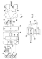
- concentration device 55 includes a plurality of assemblies 90, each containing a computer. Each assembly 90 is 8 B-channels 92 on its input side (left in the Fig. 2 ), for simplicity only two are shown. When a B-channel 92 transports a telephone call, then the module 90 is arranged to place that B-channel 92 unaltered on a link to the switching network (40 in FIG Fig. 1 ) leading B-channel 93 passes. Concerning data packets to be concentrated, the concentrator 55 operates as follows: all sub-assemblies 90 which are to concentrate data monitor a continuing channel 57, in the example with a capacity such as a B-channel, but intended for data concentration, whether data is being transmitted there. This monitoring is symbolized by lines 94. If no data is detected there, that module which has first determined this sends a data packet of a B-channel 92 to the channel 57 via a data line 95.
Landscapes
- Engineering & Computer Science (AREA)
- Computer Networks & Wireless Communication (AREA)
- Data Exchanges In Wide-Area Networks (AREA)
- Sub-Exchange Stations And Push- Button Telephones (AREA)
- Telephonic Communication Services (AREA)
Abstract
Description
Die Erfindung betrifft ein Verfahren zum Betreiben eines Telekommunikationssystems mit einer Vermittlungseinrichtung und mit Teilnehmerkanälen, über die digitale Daten in Form von Datenpaketen übertragbar sind, die jeweils eine Zieladresse enthalten.The invention relates to a method for operating a telecommunication system with a switching device and subscriber channels, via which digital data in the form of data packets are transferable, each containing a destination address.
Derartige digitale Telekommunikationssysteme sind als ISDN-Systeme bekannt und bieten neben der Möglichkeit der Übertragung digitaler Daten auch die Möglichkeit der Sprachübertragung. Diese zuletzt genannte Möglichkeit ist für den Kern der Erfindung jedoch nicht unbedingt erforderlich. Bekannte Telekommunikationssysteme mit einer Vermittlungseinrichtung sind normalerweise so dimensioniert, daß nicht sämtliche Teilnehmer gleichzeitig eine Verbindung zur Vermittlungseinrichtung und zu anderen Teilnehmern herstellen können, sondern die Kapazität der Vermittlungseinrichtung hinsichtlich gleichzeitig durchschaltbarer Kanäle ist kleiner als die Anzahl der angeschlossenen Teilnehmer. Dies kann bei der Übertragung digitaler Daten, insbesondere wenn für diese Übertragung die Dauer der einzelnen Verbindung im Vergleich z.B. zu der Dauer üblicher Telefongespräche lang ist, dazu führen, daß der Zugang zur Vermittlungseinrichtung zeitweise nicht möglich ist, weil alle zur Vermittlungseinrichtung führenden Kanäle belegt sind.Such digital telecommunication systems are known as ISDN systems and offer not only the possibility of transmitting digital data but also the possibility of voice transmission. However, this latter option is not essential to the gist of the invention. Known telecommunication systems with a switching device are normally dimensioned so that not all subscribers can simultaneously establish a connection to the switching device and to other subscribers, but the capacity of the switching device with respect to simultaneously switchable channels is smaller than the number of connected subscribers. This can result in the transmission of digital data, especially if for this transmission, the duration of the individual connection compared to eg the duration of conventional telephone calls long, the access to the switching device is temporarily not possible because all leading channels to the switching device are occupied ,
"Packet Mode Data Communications in NUMERIS, the French ISDN", Le Roux et al., beschreibt Methoden zur Datenvermittlung in NUMERIS, und offenbart unter anderem einen Frame Service Handler (FSH) welches die Konzentration von Rahmen (frames) auf eine reduzierte Anzahl von digitalen Verbindungen realisiert."Packet Mode Data Communications in NUMERIS, the French ISDN", Le Roux et al ., Describes methods of data switching in NUMERIS, and discloses, among other things, a Frame Service Handler (FSH) which reduces the concentration of frames to a reduced number of frames realized digital connections.
Der Erfindung liegt die Aufgabe zugrunde, eine Möglichkeit zu schaffen, den genannten Nachteil zu mildern.The invention has for its object to provide a way to mitigate the aforementioned disadvantage.
Diese Aufgabe wird gemäß der Erfindung durch ein Verfahren, System, bzw. eine Konzentrationsvorrichtung gemäß einem der unabhängigen Ansprüche gelöst.This object is achieved according to the invention by a method, system, or a concentration device according to one of the independent claims.
Wenn die Erfindung bei einem ISDN-Netz verwirklicht ist, bei dem ein Teilnehmerkanal eine Kapazität von 64 Kilobit (kb) hat, so wird demnach bei der Erfindung vorgesehen, daß digitale Daten unterschiedlicher Teilnehmer quasi, simultan auf einem einzigen derartigen Kanal von 64 kb konzentriert werden, und dieser einzige Kanal benötigt dann auch nur im wesentlichen diejenigen technischen Einrichtungen in der Vermittlungseinrichtung, die für ein einziges Telefongespräch erforderlich sind, was im folgenden etwas vereinfacht als ein einziger Koppelnetzpunkt bezeichnet wird. Vereinfacht ist diese Ausdrucksweise deshalb, weil ein einziges Telefongespräch von einem Teilnehmer zu einem anderen Teilnehmer meist eine Vielzahl von technischen Einrichtungen, die jeweils einen Koppelnetzpunkt bilden, in ein und derselben Vermittlungseinrichtung nacheinander durchlaufen muß, wie allgemein bekannt ist.Thus, when the invention is implemented in an ISDN network in which a subscriber channel has a capacity of 64 kilobits (kb), it is contemplated in the invention that digital data of different subscribers will be quasi concurrently concentrated on a single such channel of 64 kb Then, this single channel also only essentially requires those technical equipment in the exchange required for a single telephone call, which will be hereinafter referred to as a single switching point. Simplified, this expression is because a single telephone call from one subscriber to another subscriber usually a plurality of technical devices, each forming a switching network point, must go through in one and the same switching device successively, as is well known.
Die Anordnung kann so getroffen sein, daß im einfachsten Fall jeglicher Verkehr von digitalen Daten (insbesondere Computerdaten) im Gegensatz zu Telefongesprächen soweit wie möglich auf einen einzigen Teilnehmerkanal konzentriert wird. Dies mag z.B. ausreichend sein, wenn diese Daten von der ersten Vermittlungsstelle, bei der sie eintreffen, an eine von vornherein bekannte weitere Datenübermittlungseinrichtung weitergeschaltet werden.The arrangement may be such that, in the simplest case, any traffic of digital data (in particular computer data) is concentrated as far as possible on a single subscriber channel as opposed to telephone calls. This may be e.g. be sufficient if these data from the first switching office, where they arrive, are forwarded to a previously known further data transmission device.
Bei einer bevorzugten Ausführungsform der Erfindung ist jedoch die Konzentrationsvorrichtung derart ausgebildet, daß sie Datenpakete in Abhängigkeit von einer Zieladresse zusammenfaßt. Der Begriff Zieladresse wird in diesem Zusammenhang sehr allgemein verstanden. Es kann dies z.B. die Telefonnummer eines bestimmten Diensteanbieters (Service Provider) sein, der den Zugang zum Internet bereitstellt. Es kann auch ein für mehrere Diensteanbieter gemeinsamer Teil der jeweiligen Telefonnummer sein, wenn beispielsweise die Telefonnummern verschiedener Diensteanbieter, die insgesamt (ohne Ortsvorwahl) beispielsweise 5 Ziffern umfassen mögen, sich in den ersten drei Ziffern nicht unterscheiden. Es mag sich auch um eine Vorwahl handeln, die dafür sorgt, daß die Daten zu einer speziellen an einem anderen Ort befindlichen Vermittlungseinrichtung insgesamt weitergeleitet werden, oder um eine Vorwahl, die dafür sorgt, daß die geschilderte Konzentration der Daten verschiedener Teilnehmer in der genannten ersten Vermittlungseinrichtung überhaupt erfolgt und dabei möglicherweise gebührenmäßig begünstigt ist; dagegen erfolgt in einem solchen Fall ohne Verwendung der genannten Vorwahl beispielsweise eine Konzentration nicht und der betreffende Teilnehmer wird mit höheren Gebühren belastet.In a preferred embodiment of the invention, however, the concentration device is arranged to group data packets in response to a destination address. The term destination address is used in this Context very generally understood. It may be, for example, the telephone number of a particular service provider that provides access to the Internet. It may also be a part of the respective telephone number common to several service providers, if, for example, the telephone numbers of different service providers, which altogether (without area code) may for example comprise 5 digits, do not differ in the first three digits. It may also be a prefix which causes the data to be forwarded in its entirety to a specific exchange located elsewhere, or a prefix which ensures that the described concentration of the data of different subscribers in the first mentioned Brokerage takes place at all and may be chargeable; on the other hand, in such a case, for example, without using the said prefix, concentration does not occur and the subscriber concerned is charged higher fees.
Zur Vollständigkeit sei erwähnt, daß man im allgemeinen wohl annehmen kann, daß die tatsächliche Adresse des gewünschten Internetteilnehmers nicht von der genannten Konzentrationsvorrichtung ausgewertet wird und auch nicht Teil der vom Teilnehmer gewählten Telefonnummer ist, sondern in einem der Datenpakete der Datenübermittlung enthalten ist. Auch mag es sein, daß es sich bei der genannten Zieladresse nicht um eine tatsächliche Adresse oder einen Teil von dieser handelt, sondern um eine von der genannten Vermittlungseinrichtung oder einer anderen Vermittlungseinrichtung zugeordnete logische Adresse, die während eines bestimmten Zeitabschnitts der Datenübertragung beibehalten wird, und beispielsweise lediglich beinhaltet, daß es sich um den Teilnehmer Nr. 10 handelt, der im Augenblick Daten zusammen mit anderen Teilnehmern über einen einzigen Teilnehmerkanal der Vermittlungseinrichtung zuführt. Diese Information reicht aus, um die Daten dieses speziellen Teilnehmers nach dem Durchlaufen der Vermittlungseinrichtung in der richtigen Weise weiter zu bearbeiten und weiterzuleiten.For completeness, it should be mentioned that it is generally well to assume that the actual address of the desired Internet subscriber is not evaluated by the said concentration device and is not part of the telephone number dialed by the subscriber, but is included in one of the data packets of the data transmission. Also, it may be that the said destination address is not an actual address or a part thereof, but a logical address assigned by said switch or other switch which is maintained during a certain period of data transmission, and for example, merely implies that it is the subscriber no. 10 who is currently sharing data with other subscribers over a single subscriber channel of the switch supplies. This information is sufficient to further process and forward the data of this particular subscriber after passing through the switch.
Die durch einen oder mehrere nacheinander von den Daten zu durchlaufenden Koppelnetzpunkte bilden eine semipermanente Verbindung, das heißt, sie bleiben über längere Zeit, unter Umständen über Tage oder Wochen, in einer bestimmten Schaltstellung. Da mehrere Teilnehmer gleichzeitig Daten übertragen und dabei auch noch ein weiterer Teilnehmer hinzukommen kann, wird im Gegensatz zu einem Telefongespräch nicht für jeden Teilnehmer separat ein Weg durch des Koppelnetzwerk hindurchgeschaltet.The switching network points which are to be successively passed through by the data form a semipermanent connection, that is, they remain in a certain switching position for a relatively long time, possibly over days or weeks. Since several subscribers can simultaneously transmit data and in this case another subscriber can also be added, unlike a telephone call, a path is not switched through separately for each subscriber by the switching network.
Die Erfindung kann mit unterschiedlicher Perfektion verwirklicht sein. Bei einer ersten Stufe wird eine gewisse Anzahl von B-Kanälen, auf denen Datenpaketverkehr herrscht, im Beispiel von 32 B-Kanälen, auf einen sogenannten reservierten Kanal (das heißt: für komprimierte Daten reserviert, also kein nur einem einzigen Teilnehmer zugeordneter B-Kanal) mit einer Kapazität von 32x64 Kilobit konzentriert, ohne daß dabei beachtet wird, ob die einzelnen B-Kanäle über längere Zeit, beispielsweise eine Sekunde, sehr viele Daten übertragen, oder nur sehr wenige. Bei dieser Ausführungsform der Erfindung ergibt sich der Vorteil, daß zum Durchschalten durch eine Verbindungseinrichtung lediglich ein einziger Koppelnetzpunkt erforderlich ist. Es wird daher die Kapazität der Vermittlungseinrichtung in stark verbesserter Weise ausgenutzt.The invention can be realized with different perfection. In a first stage, a certain number of B-channels on which data packet traffic prevails, in the example of 32 B-channels, are allocated to a so-called reserved channel (that is to say for compressed data, ie no B-channel assigned to a single subscriber ) with a capacity of 32x64 kilobits, without paying attention to whether the individual B-channels for a long time, for example one second, very much data transfer, or very few. In this embodiment of the invention there is the advantage that only one single switching network point is required for switching through a connecting device. Therefore, the capacity of the switch is greatly improved.
Bei einer zweiten Perfektionierungsstufe der Erfindung wird noch beachtet, ob und welche B-Kanäle gerade viele beziehungsweise wenige Daten übertragen. Dabei werden bei einer Ausführungsform der Erfindung acht B-Kanäle gleichzeitig beobachtet. Wird angenommen, daß bei einer genügend großen Anzahl von B-Kanälen, zum Beispiel den genannten acht Kanälen, im Durchschnitt innerhalb kurzer Zeiten, die durch Pufferung der Daten in der Vermittlungseinrichtung überbrückt werden können, jeder B-Kanal nicht stärker als mit 50 % seiner Kapazität ausgenutzt wird, so können die genannten acht B-Kanäle auf vier reservierte Kanäle, die jeweils die Kapazität eines einzigen B-Kanals haben, konzentriert werden. Dabei sind diese vier genannten reservierten Kanäle dann mit 100 % ihrer Datenübertragungskapazität ausgenutzt, wenn die genannte acht zugeordneten B-Kanäle jeweils mit 50 % ihrer Kapazität ausgenutzt werden. Es kann eine Vielzahl solcher Gruppen von acht B-Kanälen auf jeweils vier reservierte Kanäle konzentriert werden, und 32 dieser reservierten Kanäle können dann auf einen einzigen Kanal mit 2 Megabit Bandbreite konzentriert werden, der wiederum über einen einzigen Koppelnetzpunkt der Vermittlungseinrichtung durchgeschaltet wird. Auf diese Weise können unter Berücksichtigung der Tatsache, daß die einzelnen B-Kanäle im genannten Beispiel nicht ständig Daten transportieren, insgesamt 64 B-Kanäle gleichzeitig durch einen einzigen Koppelnetzpunkt durchgeschaltet werden. Hier liegt der Vorteil in einer noch besseren Ausnutzung des Koppelnetzwerkes und darüberhinaus in einer besseren Ausnutzung der Datenübertragungskapazität der Kanäle des Telekommunikationssystems.In a second perfecting stage of the invention, it is still considered whether and which B-channels are currently transmitting many or a few data. In this case, in one embodiment of the invention, eight B-channels observed simultaneously. Assuming that for a sufficiently large number of B-channels, for example the said eight channels, on average within short times, which can be bridged by buffering the data in the switch, each B-channel will not be stronger than 50% of its Capacity is exploited, so the said eight B-channels can be concentrated on four reserved channels, each having the capacity of a single B-channel. These four reserved channels are then used with 100% of their data transmission capacity, if the said eight allocated B-channels are used each with 50% of their capacity. A plurality of such groups of eight B-channels can be concentrated to four reserved channels each, and 32 of these reserved channels can then be concentrated on a single 2-megabit bandwidth channel, which in turn is switched through a single switching point of the switch. In this way, taking into account the fact that the individual B-channels do not constantly carry data in the example mentioned, a total of 64 B-channels can be switched through simultaneously by a single switching network point. Here, the advantage lies in an even better utilization of the switching network and, moreover, in a better utilization of the data transmission capacity of the channels of the telecommunication system.
Der oben genannte Kanal mit einer Kapazität von 2 Megabit (2x1024x1024 Bit) überträgt die einzelnen Datenpakete mit einer Impulsfolgefrequenz, die 32 mal so groß ist wie bei einem B-Kanal. Die Übertragung von Datenpaketen aus einem B-Kanal schließt daher das Zwischenspeichern eines Datenpakets des B-Kanals und daraufhin das Einspeisen dieses Datenpakets in den reservierten Kanal mit dessen Impulsfolgefrequenz ein.The above mentioned 2 megabit (2x1024x1024 bit) channel transmits the individual data packets at a pulse repetition rate that is 32 times greater than a B channel. The transmission of data packets from a B-channel therefore includes the buffering of a data packet of the B-channel and then feeding this data packet into the reserved channel with its pulse repetition frequency.
Bei einfachen Ausführungsformen der Erfindung wird ohne Koordinierung versucht, die Daten zwecks Komprimierung in den reservierten Kanal einzuspeisen. Wenn hierbei die eingespeisten Daten mit auf dem reservierten Kanal befindlichen Daten kollidieren, so kann dies in bekannter Weise durch Kollisionsselbsterkennung (collision auto detect) festgestellt werden. Der Versuch des Einspeisens in den reservierten Kanal ist in einem solchen Fall fehlgeschlagen und muß wiederholt werden. Zur optimalen Ausnutzung und schnellstmöglichen Weiterleitung der Datenpakete ist jedoch bei einer bevorzugten Ausführungsform der Erfindung vorgesehen, daß der Datenfluß auf dem reservierten Kanal überwacht wird und das Einspeisen so gesteuert wird, daß eingespeiste Datenpakete möglichst nicht mit anderen Daten kollidieren. Diese Überwachung wird bei erfindungsgemäßen Ausführungsformen des Telekommunikationssystems durch eine Überwachungsvorrichtung bewirkt, die mindestens einen reservierten Kanal und eine Mehrzahl von B-Kanälen beziehungsweise den B-Kanälen zugeordnete Zwischenspeicher, in denen jeweils eines der Datenpakete zur Einspeisung auf einen reservierten Kanal vorrätig gehalten wird, überwacht und ein Einspeisen der Datenpakete auf den überwachten reservierten Kanal dann veranlaßt, wenn dies gerade möglich ist. Bei einem derartigen Vorgehen und einer derartigen Anordnung kann auch einer raschen Änderung, insbesondere einer raschen Zunahme des Datenverkehrs auf den B-Kanälen Rechnung getragen werden. Daneben kann Kollisionserkennung trotzdem noch nützlich sein.In simple embodiments of the invention, without coordination, it is attempted to feed the data into the reserved channel for compression. If, in this case, the data fed in collide with data located on the reserved channel, this can be determined in a known manner by collision auto-detection. The attempt to feed into the reserved channel has failed in such a case and must be repeated. For optimal utilization and fastest possible forwarding of the data packets, however, is provided in a preferred embodiment of the invention that the data flow is monitored on the reserved channel and the feed is controlled so that fed data packets as possible do not collide with other data. This monitoring is effected in embodiments of the telecommunication system according to the invention by a monitoring device, which monitors at least one reserved channel and a plurality of B-channels or buffers assigned to the B-channels, in each of which one of the data packets for supply to a reserved channel is kept in stock and then causing the data packets to be fed to the monitored reserved channel, if at all possible. With such a procedure and such an arrangement, a rapid change, in particular a rapid increase in data traffic on the B channels, can also be taken into account. In addition, collision detection can still be useful.
Bei einer Ausführungsform der Erfindung weist das System eine Verteilvorrichtung auf, die zusammengefaßte Datenpakete auf mehrere Kanäle, z.B. Teilnehmerkanäle aufteilt, wobei dies insbesondere dazu dienen kann, die Datenpakete mindestens einem durch eine Zieladresse bestimmten Teilnehmer oder Diensteanbieter zuzuleiten. Dieser kann sich entweder an einem anderen Ort als der die digitale Daten absendende Teilnehmer befinden oder er wird von der obengenannten Koppeleinrichtung unmittelbar erreicht.In one embodiment of the invention, the system comprises a distribution device which splits combined data packets onto a plurality of channels, for example subscriber channels, wherein this can in particular serve to determine the data packets at least one by a destination address To provide subscribers or service providers. This can either be at a different location than the participants sending the digital data or it is reached directly by the above-mentioned coupling device.
Bisher wurden lediglich die Daten betrachtet, die von einem Teilnehmer in Richtung z.B. zum Internet abgesendet werden. Die verschiedenen Teile der Verbindungseinrichtung und die Konzentrationsvorrichtung sind jedoch zweckmäßig so ausgebildet, daß sie auch Daten, die in Gegenrichtung fließen, dem jeweiligen Teilnehmer zuführen, wie dies auch der Fall ist, wenn in herkömmlicher Weise jedem Teilnehmer für seine Datenübertragung ein eigener Teilnehmerkanal für die gesamte Datenübertragung zugeordnet wird.So far, only the data that has been sent by a subscriber towards e.g. sent to the internet. However, the various parts of the connection device and the concentration device are expediently designed so that they also feed data flowing in the opposite direction to the respective subscriber, as is the case when conventionally each subscriber for its data transmission a separate subscriber channel for the entire data transfer is assigned.
Weitere Merkmale und Vorteile der Erfindung ergeben sich aus der nachfolgenden Beschreibung von Ausführungsbeispielen der Erfindung anhand der Zeichnung, die erfindungswesentliche Einzelheiten zeigt, und aus den Ansprüchen. Die einzelnen Merkmale können hier einzeln für sich oder zu mehreren in beliebiger Kombination bei einer Ausführungsform der Erfindung verwirklicht sein.Further features and advantages of the invention will become apparent from the following description of embodiments of the invention with reference to the drawing, which shows details essential to the invention, and from the claims. The individual features may here be implemented individually for themselves or for several in any combination in an embodiment of the invention.
Es zeigen:
-
Fig. 1 eine schematische Darstellung eines erfindungsgemäßen Telekommunikationssystems, -
Fig. 2 eine schematische Darstellung einer Konzentrationsvorrichtung. -
Fig. 1 zeigt schematisch ein
-
Fig. 1 a schematic representation of a telecommunication system according to the invention, -
Fig. 2 a schematic representation of a concentration device. -
Fig. 1 shows a schematic
Die Vermittlungseinrichtung 10 enthält ein Koppelnetz 40 mit einer Vielzahl von Koppelnetzpunkten, die jeweils zum Durchschalten eines einzigen Kanals dienen, jedenfalls dann, wenn über die Kanäle Telefongespräche oder analoge Daten (über Modem) übertragen werden. Dann unterscheidet sich die Arbeitskräfte der Vermittlungseinrichtung nicht von der seither üblichen Funktion. Nachfolgend wird vereinfachend davon gesprochen, daß ein Telefongespräch oder eine andere Verbindung durch "einen" Koppelnetzpunkt durchgeschaltet wird, obwohl in der Realität ein solcher Kanal im allgemeinen über mehrere Koppelnetzpunkte durchgeschaltet wird.The
Über das Endgerät 11 wird gerade ein ISDN-Telefongespräch geführt. Vor Beginn des Geschäfts hatte der Teilnehmer den Telefonhörer abgenommen und die gewünschte Telefonnummer gewählt. Diese Informationen wurden der Vermittlungseinrichtung 10 durch den D-Kanal mitgeteilt, und die Vermittlungseinrichtung hat den B-Kanal des Endgeräts 11 an eine bestimmte Eingangsschaltung 51 aus einer Vielzahl solcher Schaltungen vor dem Koppelnetz 40 angeschaltet, von wo aus dieser B-Kanal entsprechend der gewählten Telefonnummer durch das Koppelnetz in herkömmlicher Weise durchgeschaltet wird.About the terminal 11 is currently being conducted an ISDN telephone conversation. Before starting the transaction, the subscriber had picked up the telephone receiver and dialed the desired telephone number. This information has been communicated to the
Vom Endgerät 12 war der Vermittlungseinrichtung 10 zu Beginn der Verbindung über den D-Kanal mitgeteilt worden, daß digitale Daten in Paketform zum Diensteanbieter 30 (ISP1) übertragen werden sollen. Aus der gewählten Telefonnummer dieses Diensteanbieter erkennt eine Überwachungsvorrichtung 54 in der Vermittlungseinrichtung 10, daß diese Daten auf einen für konzentrierte Daten reservierten Kanal konzentriert werden sollen. Die Vermittlungseinrichtung 10 hat daraufhin den B-Kanal des Endgeräts 12 mit einer Konzentrationsvorrichtung 55 (Internet-Rahmen-Konzentrator, Internet Frame Concentrator, IFC) aus einer Vielzahl solcher Vorrichtungen verbunden und der Konzentrationsvorrichtung 55 mitgeteilt, daß die Datenpakete konzentriert werden sollen. (Telefongespräche werden ebenfalls dem Eingang der Konzentrationsvorrichtung zugeführt, in dieser aber nicht konzentriert, sondern in nicht gezeigter Weise über einen B-Kanal dem Koppelnetz 40 zugeführt.) In der Zeichnung ist angedeutet, daß mit dem Eingang der Konzentrationsvorrichtung 55 insgesamt acht B-Kanäle verbunden werden können.From the terminal 12, the
Die Konzentrationsvorrichtung 55 ist so ausgebildet, daß sie die Datenpakete von acht B-Kanälen auf einen einzigen Kanal 57 mit einer Kapazität von 2 Megabit zusammenfaßt. Dieser Kanal 57 wird von dem Koppelnetz als Einheit durchgeschaltet, also durch einen einzigen Koppelnetzpunkt im theoretisch einfachsten Fall.The
Bekannte Koppelnetze haben im Normalfall die Fähigkeit, Kanäle mit 2 Megabit Bandbreite durchzuschalten. Wo dies nicht der Fall ist, kann die erforderliche Bandbreite möglicherweise einfach durch zusätzliche Verstärker, erforderlichenfalls in Kombination mit Filtern, bereitgestellt werden.Known coupling networks normally have the capability of switching through channels with 2 megabit bandwidth. Where this is not the case, the required bandwidth may possibly be provided simply by additional amplifiers, if necessary in combination with filters.
Die Konzentration mehrerer B-Kanäle auf einen einzigen Kanal bewirkt eine bessere Ausnutzung des Koppelnetzes 40, weil ohne eine derartige Konzentration mehr Koppelnetzpunkte benötigt werden als mit der geschilderten Konzentration. Eine derartige Konzentration ist jedenfalls dann sinnvoll, wenn die Daten der genannten B-Kanäle zu einer einzigen Zieladresse gelangen sollen, z.B. zu dem Diensteanbieter 30. Wenn sich die Diensteanbieter 30 und 31 in dem gleichen, von der Vermittlungseinrichtung 10 weit entfernten Ort befinden, ist das Konzentrieren mehrerer B-Kanäle mit Daten für diese zwei Diensteanbieter auf einen einzigen Kanal ebenfalls sinnvoll. Es muß dann nur an dem genannten entfernten Ort, genauer in dessen Vermittlungseinrichtung, eine Verteilung auf die beiden genannten Diensteanbieter 30 und 31 erfolgen, die bei der herkömmlichen Technik die Anrufe von Teilnehmern, die den Zugang zum Internet wünschen, auf einer Vielzahl von Kanälen, die je einem einzigen Teilnehmer zugeordnet sind, erwarten.The concentration of several B-channels on a single channel causes a better utilization of the
Hierzu können die 2-Megabit-Kanäle durch geeignete Einrichtungen in einzelne B-Kanäle aufgeteilt werden, die dann anschließend mit je einem aus einer Vielzahl von Telekommunikations-Anschlüssen des jeweiligen Diensteanbieters verbunden werden.For this purpose, the 2-megabit channels can be replaced by suitable Devices are divided into individual B channels, which are then then connected to one of a variety of telecommunications connections of each service provider.
Es versteht sich, daß sich die Erfindung auch auf andere Telekommunikationsnetze, die vom geschilderten Netz technisch abweichen, erstreckt.It is understood that the invention also extends to other telecommunications networks that differ technically from the network described.
Die Verbindung des Teilnehmerendgeräts 13 mit der Vermittlungseinrichtung 10 unterscheidet sich vom Teilnehmerendgerät 12 nur dadurch, daß sich die zugeordnete Konzentrationsvorrichtung 55' in einer abgesetzten Teilnehmereinheit (Remote Subscriber Unit, RSU) 70 befindet, die viele Kilometer von der Vermittlungseinrichtung 10 entfernt ist und mit dieser über einen Kanal 72 mit einer Kapazität von 2 Megabit für Nutzdaten verbunden ist. Über den Kanal 72 können auch Steuerungsdaten übertragen werden, die bei Anwahl eines Internet-Diensteanbieters den B-Kanal des Endgeräts 13 an die Konzentrationsvorrichtung 55' anschalten und den Konzentrationsvorgang aktivieren. Bei einer anderen Ausführungsform der Erfindung enthält die Einheit 70 selbst die erforderlichen Einrichtungen, um über das Anschalten an die Konzentrationsvorrichtung 55' zu entscheiden.The connection of the
Im Beispiel erfolgt die Weiterleitung der Daten zu den Diensteanbietern 30 und 31 über eine Adaptereinheit 80 (Daten-Anwendungs-Netz-Adapter, Data Application Network Adapter, DANA), dem eine Vielzahl von 2-Megabit-Kanälen 81 aus dem Vermittlungsnetzwerk 20 zugeführt werden; nur einer ist gezeigt. Die Adaptereinheit 80 isoliert die einzelnen Paketdaten, und diese werden über ein Frame-Relay-Netz 82 den jeweils gewünschten Diensteanbietern 30 bzw. 31 zugeführt.In the example, the data is forwarded to the
Die in
Claims (11)
- Method of operating a telecommunication system with a switching facility and subscriber channels across which digital data in the form of data packets can be transmitted, each of which contains a destination address, and the data packets of several subscriber channels are combined and fed into a single outgoing channel, characterised in that the method comprises:monitoring the outgoing channel in order to detect whether data is currently being transmitted on the outgoing channel; andif no data is detected on the outgoing channel, sending a data packet of a subscriber channel onto the outgoing channel.
- Method as claimed in claim 1, characterised in that the outgoing channel is monitored by several modules (90) of a concentrator device (55, 55'), each of which combines data packets of several subscriber channels, and if no data is detected on the outgoing channel, a data packet of a subscriber channel is sent to the outgoing channel by the module which first detected that this was the case.
- Method as claimed in claim 1, characterised in that data packets are combined on the basis of a destination address.
- Telecommunication system with subscriber channels across which digital data in the form of data packets can be transmitted, each of which contains a destination address, and with a switching facility (10) with coupling network points, each of which is able to switch a subscriber channel to an outgoing channel, in particular for implementing the method as claimed in claim 1, and a concentrator device (55, 55') is provided which combines the data packets of several subscriber channels and feeds them into a single channel which is switched via a coupling network point and outputs to the switching facility,
characterised in that the concentrator device has a monitoring device which monitors the outgoing channel and then causes the data packets to be fed onto the outgoing channel if this is currently possible,
and the monitoring device monitors whether data is currently being transmitted on the outgoing channel and if no data is detected, a data packet of a subscriber channel is sent to the outgoing channel. - System as claimed in claim 4, characterised in that the concentrator device comprises several modules (90), each of which is configured to combine data packets of several subscriber channels, and each of the modules monitors the outgoing channel, and if no data is detected there, the module which first detected this sends a data packet of a subscriber onto the outgoing channel.
- System as claimed in claim 4 or 5, characterised in that it is also designed to transmit speech signals to the subscriber lines.
- System as claimed in one of claims 4 to 6, characterised in that the concentrator device (55, 55') is configured so that it combines data packets on the basis of a destination address.
- System as claimed in one of claims 4 to 7, characterised in that a distributor device is provided, which distributes the combined data packets to several channels, e.g. subscriber channels, in particular in order to route the data packets to at least one subscriber or service provider determined on the basis of a destination address.
- System as claimed in one of claims 4 to 8, characterised in that it is an ISDN system.
- Concentrator device suitable for use with a method as claimed in one of claims 1 to 3 and/or with a system as claimed in one of claims 4 to 9, which concentrator device contains at least one module (90) for concentrating on a single outgoing channel (57) data arriving on several subscriber channels (92) which has to be concentrated in the form of data packets,
characterised in that the concentrator device has a monitoring device which monitors the outgoing channel and causes the data packets to be fed to the monitored channel if this is currently possible,
and the monitoring device monitors whether data is currently being transmitted on the outgoing channel and if no data is detected there, a data packet of a subscriber channel is sent to the outgoing channel. - Device as claimed in claim 10, characterised in that it can be switched so that it routes data which does not have to be concentrated to associated outgoing B channels (93).
Applications Claiming Priority (2)
| Application Number | Priority Date | Filing Date | Title |
|---|---|---|---|
| DE19840329A DE19840329A1 (en) | 1998-09-04 | 1998-09-04 | Telecommunication system with switching device and data concentrator for access to the Internet |
| DE19840329 | 1998-09-04 |
Related Child Applications (1)
| Application Number | Title | Priority Date | Filing Date |
|---|---|---|---|
| EP10185111.1 Division-Into | 2010-09-30 |
Publications (3)
| Publication Number | Publication Date |
|---|---|
| EP0984658A2 EP0984658A2 (en) | 2000-03-08 |
| EP0984658A3 EP0984658A3 (en) | 2004-12-29 |
| EP0984658B1 true EP0984658B1 (en) | 2011-06-08 |
Family
ID=7879788
Family Applications (1)
| Application Number | Title | Priority Date | Filing Date |
|---|---|---|---|
| EP99440230A Expired - Lifetime EP0984658B1 (en) | 1998-09-04 | 1999-08-20 | Telecommunication system with switching device and data concentrator for access to Internet |
Country Status (4)
| Country | Link |
|---|---|
| US (2) | US6687258B1 (en) |
| EP (1) | EP0984658B1 (en) |
| AT (1) | ATE512552T1 (en) |
| DE (1) | DE19840329A1 (en) |
Families Citing this family (3)
| Publication number | Priority date | Publication date | Assignee | Title |
|---|---|---|---|---|
| JP2001285478A (en) * | 2000-03-31 | 2001-10-12 | Fujitsu Ltd | Method for controlling exchange line concentrating part connection and its exchange |
| EP1206089A3 (en) * | 2000-06-21 | 2002-05-22 | Alcatel | Method, adaptation module, network node and exchange for the access of a telecommunication terminal to the internet |
| EP1509033B1 (en) * | 2003-08-19 | 2012-10-17 | Alcatel Lucent | Method and devices for connecting IP terminations and PSTN terminations |
Family Cites Families (15)
| Publication number | Priority date | Publication date | Assignee | Title |
|---|---|---|---|---|
| US4922486A (en) * | 1988-03-31 | 1990-05-01 | American Telephone And Telegraph Company | User to network interface protocol for packet communications networks |
| US4970723A (en) * | 1988-09-30 | 1990-11-13 | At&T Bell Laboratories | ISDN, basic rate interface arranged for quad voice |
| US4996685A (en) * | 1989-04-10 | 1991-02-26 | Bell Communications Research, Inc. | Technique for dynamically changing an ISDN connection during a host session |
| US5398249A (en) * | 1992-05-14 | 1995-03-14 | Industrial Technology Research Institute | System for providing simultaneous multiple circuit-switched type communications on an ISDN basic rate interface |
| EP0661900A3 (en) | 1993-12-22 | 1997-10-22 | Siemens Ag | Controller for packet data in an STM switch. |
| US5959988A (en) * | 1996-06-24 | 1999-09-28 | Ericsson, Inc. | Telecommunications switch including an integrated internet access server |
| CA2180685C (en) * | 1996-07-08 | 2003-09-09 | Wynn Quon | Internet telephony gateway |
| US5748628A (en) * | 1996-11-05 | 1998-05-05 | Interack Communications, Inc. | ISDN D-channel signaling discriminator |
| US6055224A (en) * | 1996-12-30 | 2000-04-25 | Siemens Information And Communicatiion Networks, Inc. | Method and system for handling telecommunications data traffic |
| US6075796A (en) * | 1997-03-17 | 2000-06-13 | At&T | Methods and apparatus for providing improved quality of packet transmission in applications such as internet telephony |
| US5999609A (en) * | 1997-04-04 | 1999-12-07 | Sun Microsystems, Inc. | Computer-telephony (CT) system including an electronic call request |
| AU5831398A (en) * | 1997-04-24 | 1998-10-29 | Motorola, Inc. | Method and apparatus for supporting ISDN feature phones in hybrid fiber coaxial network |
| US6035020A (en) * | 1997-08-26 | 2000-03-07 | Nec Usa, Inc. | Modem data call bypass of a telephone network voice switch |
| US6349096B1 (en) * | 1997-09-22 | 2002-02-19 | Integrated Telecom Express, Inc. | Configurable digital subscriber loop access and end-to-end data and analog voice connection system |
| DE19745961A1 (en) * | 1997-10-17 | 1999-04-22 | Cit Alcatel | Device and method for establishing a call connection |
-
1998
- 1998-09-04 DE DE19840329A patent/DE19840329A1/en not_active Withdrawn
-
1999
- 1999-08-20 EP EP99440230A patent/EP0984658B1/en not_active Expired - Lifetime
- 1999-08-20 AT AT99440230T patent/ATE512552T1/en active
- 1999-08-27 US US09/385,626 patent/US6687258B1/en not_active Ceased
-
2006
- 2006-02-03 US US11/347,790 patent/USRE42069E1/en not_active Expired - Lifetime
Also Published As
| Publication number | Publication date |
|---|---|
| ATE512552T1 (en) | 2011-06-15 |
| US6687258B1 (en) | 2004-02-03 |
| EP0984658A2 (en) | 2000-03-08 |
| EP0984658A3 (en) | 2004-12-29 |
| USRE42069E1 (en) | 2011-01-25 |
| DE19840329A1 (en) | 2000-03-09 |
Similar Documents
| Publication | Publication Date | Title |
|---|---|---|
| EP0631454B1 (en) | Method for establishing virtual connections in packet switching networks | |
| DE69632240T2 (en) | Method and system for controlling transmission speeds of sources in ATM networks | |
| EP0276776A2 (en) | Digital switching network for circuit and packet switching, and switching matrix element therefor | |
| EP0121188A2 (en) | Method and circuit arrangement for the transmission of data signals between subscriber's stations of a data network | |
| EP0682422A2 (en) | Method and device for synchronising redundantly transmitted information cell streams | |
| EP0762716A2 (en) | Method, communication system and conference unit to realise conferences | |
| EP1130853A1 (en) | Circuit arrangement for changeover to standby of transmission installations in ring architectures with MPLS-packets | |
| DE4329056C2 (en) | Method for operating a digital communication network consisting of several subsystems | |
| EP0751693A2 (en) | ATM communication network | |
| DE19715799C2 (en) | Local network with means of implementation | |
| EP0984658B1 (en) | Telecommunication system with switching device and data concentrator for access to Internet | |
| EP0332809A2 (en) | Digital communication switching system, especially a private branch exchange, for speech, data, pictures, video telephony, etc. | |
| DE10343615A1 (en) | Network node for an optical communications network | |
| DE69738082T2 (en) | SYSTEM AND METHOD FOR TIME COMPENSATION IN A DYNAMIC PACKAGED NETWORK | |
| EP0998093B1 (en) | Method to transmit reverse channel data on a connection between a terminal and a server in a packet switched network | |
| EP0475180A1 (en) | Method for transmission of communication blocks between transmission lines of existing connections in a switching exchange | |
| EP0343319B1 (en) | Digital-information transmission method for communication-switching systems | |
| DE3233221A1 (en) | CIRCUIT ARRANGEMENT FOR TRANSMITTING SIGNALS BETWEEN SUBSCRIBER CONNECTION LINES AND AT LEAST ONE TRANSMISSION LINE OF A SERVICE-INTEGRATED TELECOMMUNICATION SYSTEM | |
| DE3431762A1 (en) | METHOD FOR TRANSMITTING DATA SIGNALS BETWEEN PARTICIPANTS OF A DATA SWITCHING SYSTEM | |
| DE19524029C1 (en) | Access network connection method for communications system | |
| EP0111114A2 (en) | Circuit arrangement for a telephone exchange, expecially a private branch exchange with additional data communication | |
| EP0143202B1 (en) | Digital telecommunication system with subscribers' loops in a star configuration | |
| EP0857003A2 (en) | Apparatus for realising redundancy circuits of communication devices in ring architectures for the bidirectional transmission of ATM cells | |
| DE3225684A1 (en) | TERMINAL CIRCUIT FOR A SUBSCRIBER DEVICE IN A DIGITAL TELECOMMUNICATION SYSTEM | |
| DE4227736B4 (en) | Network with a branch and channel distribution device |
Legal Events
| Date | Code | Title | Description |
|---|---|---|---|
| PUAI | Public reference made under article 153(3) epc to a published international application that has entered the european phase |
Free format text: ORIGINAL CODE: 0009012 |
|
| AK | Designated contracting states |
Kind code of ref document: A2 Designated state(s): AT BE CH CY DE DK ES FI FR GB GR IE IT LI LU MC NL PT SE |
|
| AX | Request for extension of the european patent |
Free format text: AL;LT;LV;MK;RO;SI |
|
| PUAL | Search report despatched |
Free format text: ORIGINAL CODE: 0009013 |
|
| AK | Designated contracting states |
Kind code of ref document: A3 Designated state(s): AT BE CH CY DE DK ES FI FR GB GR IE IT LI LU MC NL PT SE |
|
| AX | Request for extension of the european patent |
Extension state: AL LT LV MK RO SI |
|
| RIC1 | Information provided on ipc code assigned before grant |
Ipc: 7H 04L 12/28 B Ipc: 7H 04Q 11/04 A |
|
| 17P | Request for examination filed |
Effective date: 20050509 |
|
| 17Q | First examination report despatched |
Effective date: 20050608 |
|
| AKX | Designation fees paid |
Designated state(s): AT BE CH CY DE DK ES FI FR GB GR IE IT LI LU MC NL PT SE |
|
| RAP1 | Party data changed (applicant data changed or rights of an application transferred) |
Owner name: NAXOS DATA LLC |
|
| GRAP | Despatch of communication of intention to grant a patent |
Free format text: ORIGINAL CODE: EPIDOSNIGR1 |
|
| GRAS | Grant fee paid |
Free format text: ORIGINAL CODE: EPIDOSNIGR3 |
|
| GRAA | (expected) grant |
Free format text: ORIGINAL CODE: 0009210 |
|
| AK | Designated contracting states |
Kind code of ref document: B1 Designated state(s): AT BE CH CY DE DK ES FI FR GB GR IE IT LI LU MC NL PT SE |
|
| REG | Reference to a national code |
Ref country code: GB Ref legal event code: FG4D Free format text: NOT ENGLISH |
|
| REG | Reference to a national code |
Ref country code: CH Ref legal event code: EP |
|
| REG | Reference to a national code |
Ref country code: IE Ref legal event code: FG4D Free format text: LANGUAGE OF EP DOCUMENT: GERMAN |
|
| REG | Reference to a national code |
Ref country code: DE Ref legal event code: R096 Ref document number: 59915273 Country of ref document: DE Effective date: 20110721 |
|
| REG | Reference to a national code |
Ref country code: NL Ref legal event code: VDEP Effective date: 20110608 |
|
| PG25 | Lapsed in a contracting state [announced via postgrant information from national office to epo] |
Ref country code: SE Free format text: LAPSE BECAUSE OF FAILURE TO SUBMIT A TRANSLATION OF THE DESCRIPTION OR TO PAY THE FEE WITHIN THE PRESCRIBED TIME-LIMIT Effective date: 20110608 |
|
| PG25 | Lapsed in a contracting state [announced via postgrant information from national office to epo] |
Ref country code: ES Free format text: LAPSE BECAUSE OF FAILURE TO SUBMIT A TRANSLATION OF THE DESCRIPTION OR TO PAY THE FEE WITHIN THE PRESCRIBED TIME-LIMIT Effective date: 20110919 Ref country code: FI Free format text: LAPSE BECAUSE OF FAILURE TO SUBMIT A TRANSLATION OF THE DESCRIPTION OR TO PAY THE FEE WITHIN THE PRESCRIBED TIME-LIMIT Effective date: 20110608 Ref country code: GR Free format text: LAPSE BECAUSE OF FAILURE TO SUBMIT A TRANSLATION OF THE DESCRIPTION OR TO PAY THE FEE WITHIN THE PRESCRIBED TIME-LIMIT Effective date: 20110909 Ref country code: CY Free format text: LAPSE BECAUSE OF FAILURE TO SUBMIT A TRANSLATION OF THE DESCRIPTION OR TO PAY THE FEE WITHIN THE PRESCRIBED TIME-LIMIT Effective date: 20110608 |
|
| PG25 | Lapsed in a contracting state [announced via postgrant information from national office to epo] |
Ref country code: NL Free format text: LAPSE BECAUSE OF FAILURE TO SUBMIT A TRANSLATION OF THE DESCRIPTION OR TO PAY THE FEE WITHIN THE PRESCRIBED TIME-LIMIT Effective date: 20110608 |
|
| REG | Reference to a national code |
Ref country code: IE Ref legal event code: FD4D |
|
| PG25 | Lapsed in a contracting state [announced via postgrant information from national office to epo] |
Ref country code: IE Free format text: LAPSE BECAUSE OF FAILURE TO SUBMIT A TRANSLATION OF THE DESCRIPTION OR TO PAY THE FEE WITHIN THE PRESCRIBED TIME-LIMIT Effective date: 20110608 Ref country code: PT Free format text: LAPSE BECAUSE OF FAILURE TO SUBMIT A TRANSLATION OF THE DESCRIPTION OR TO PAY THE FEE WITHIN THE PRESCRIBED TIME-LIMIT Effective date: 20111010 |
|
| BERE | Be: lapsed |
Owner name: NAXOS DATA LLC Effective date: 20110831 |
|
| PG25 | Lapsed in a contracting state [announced via postgrant information from national office to epo] |
Ref country code: MC Free format text: LAPSE BECAUSE OF NON-PAYMENT OF DUE FEES Effective date: 20110831 |
|
| REG | Reference to a national code |
Ref country code: CH Ref legal event code: PL |
|
| PLBE | No opposition filed within time limit |
Free format text: ORIGINAL CODE: 0009261 |
|
| STAA | Information on the status of an ep patent application or granted ep patent |
Free format text: STATUS: NO OPPOSITION FILED WITHIN TIME LIMIT |
|
| PG25 | Lapsed in a contracting state [announced via postgrant information from national office to epo] |
Ref country code: CH Free format text: LAPSE BECAUSE OF NON-PAYMENT OF DUE FEES Effective date: 20110831 Ref country code: LI Free format text: LAPSE BECAUSE OF NON-PAYMENT OF DUE FEES Effective date: 20110831 |
|
| 26N | No opposition filed |
Effective date: 20120309 |
|
| PG25 | Lapsed in a contracting state [announced via postgrant information from national office to epo] |
Ref country code: BE Free format text: LAPSE BECAUSE OF NON-PAYMENT OF DUE FEES Effective date: 20110831 Ref country code: IT Free format text: LAPSE BECAUSE OF FAILURE TO SUBMIT A TRANSLATION OF THE DESCRIPTION OR TO PAY THE FEE WITHIN THE PRESCRIBED TIME-LIMIT Effective date: 20110608 |
|
| PG25 | Lapsed in a contracting state [announced via postgrant information from national office to epo] |
Ref country code: DK Free format text: LAPSE BECAUSE OF FAILURE TO SUBMIT A TRANSLATION OF THE DESCRIPTION OR TO PAY THE FEE WITHIN THE PRESCRIBED TIME-LIMIT Effective date: 20110608 |
|
| REG | Reference to a national code |
Ref country code: DE Ref legal event code: R097 Ref document number: 59915273 Country of ref document: DE Effective date: 20120309 |
|
| REG | Reference to a national code |
Ref country code: AT Ref legal event code: MM01 Ref document number: 512552 Country of ref document: AT Kind code of ref document: T Effective date: 20110820 |
|
| PG25 | Lapsed in a contracting state [announced via postgrant information from national office to epo] |
Ref country code: AT Free format text: LAPSE BECAUSE OF NON-PAYMENT OF DUE FEES Effective date: 20110820 |
|
| PG25 | Lapsed in a contracting state [announced via postgrant information from national office to epo] |
Ref country code: LU Free format text: LAPSE BECAUSE OF NON-PAYMENT OF DUE FEES Effective date: 20110820 |
|
| REG | Reference to a national code |
Ref country code: FR Ref legal event code: PLFP Year of fee payment: 17 |
|
| REG | Reference to a national code |
Ref country code: FR Ref legal event code: PLFP Year of fee payment: 18 |
|
| REG | Reference to a national code |
Ref country code: FR Ref legal event code: PLFP Year of fee payment: 19 |
|
| REG | Reference to a national code |
Ref country code: DE Ref legal event code: R082 Ref document number: 59915273 Country of ref document: DE Representative=s name: DTS PATENT- UND RECHTSANWAELTE SCHNEKENBUEHL U, DE |
|
| REG | Reference to a national code |
Ref country code: FR Ref legal event code: TP Owner name: XYLON LLC, US Effective date: 20170814 |
|
| REG | Reference to a national code |
Ref country code: GB Ref legal event code: 732E Free format text: REGISTERED BETWEEN 20170914 AND 20170920 |
|
| REG | Reference to a national code |
Ref country code: DE Ref legal event code: R082 Ref document number: 59915273 Country of ref document: DE Representative=s name: DTS PATENT- UND RECHTSANWAELTE SCHNEKENBUEHL U, DE Ref country code: DE Ref legal event code: R081 Ref document number: 59915273 Country of ref document: DE Owner name: XYLON LLC, LAS VEGAS, US Free format text: FORMER OWNER: NAXOS DATA LLC, LAS VEGAS, NEV., US |
|
| REG | Reference to a national code |
Ref country code: FR Ref legal event code: PLFP Year of fee payment: 20 |
|
| PGFP | Annual fee paid to national office [announced via postgrant information from national office to epo] |
Ref country code: FR Payment date: 20180718 Year of fee payment: 20 Ref country code: DE Payment date: 20180716 Year of fee payment: 20 |
|
| PGFP | Annual fee paid to national office [announced via postgrant information from national office to epo] |
Ref country code: GB Payment date: 20180726 Year of fee payment: 20 |
|
| REG | Reference to a national code |
Ref country code: DE Ref legal event code: R071 Ref document number: 59915273 Country of ref document: DE |
|
| REG | Reference to a national code |
Ref country code: GB Ref legal event code: PE20 Expiry date: 20190819 |
|
| PG25 | Lapsed in a contracting state [announced via postgrant information from national office to epo] |
Ref country code: GB Free format text: LAPSE BECAUSE OF EXPIRATION OF PROTECTION Effective date: 20190819 |