EP1235207A2 - Method and apparatus of magnetically transferring information signal from master medium to slave medium - Google Patents
Method and apparatus of magnetically transferring information signal from master medium to slave medium Download PDFInfo
- Publication number
- EP1235207A2 EP1235207A2 EP02003193A EP02003193A EP1235207A2 EP 1235207 A2 EP1235207 A2 EP 1235207A2 EP 02003193 A EP02003193 A EP 02003193A EP 02003193 A EP02003193 A EP 02003193A EP 1235207 A2 EP1235207 A2 EP 1235207A2
- Authority
- EP
- European Patent Office
- Prior art keywords
- magnetic field
- slave
- medium
- magnetic
- transferring
- Prior art date
- Legal status (The legal status is an assumption and is not a legal conclusion. Google has not performed a legal analysis and makes no representation as to the accuracy of the status listed.)
- Withdrawn
Links
Images


Classifications
-
- G—PHYSICS
- G11—INFORMATION STORAGE
- G11B—INFORMATION STORAGE BASED ON RELATIVE MOVEMENT BETWEEN RECORD CARRIER AND TRANSDUCER
- G11B5/00—Recording by magnetisation or demagnetisation of a record carrier; Reproducing by magnetic means; Record carriers therefor
- G11B5/84—Processes or apparatus specially adapted for manufacturing record carriers
-
- G—PHYSICS
- G11—INFORMATION STORAGE
- G11B—INFORMATION STORAGE BASED ON RELATIVE MOVEMENT BETWEEN RECORD CARRIER AND TRANSDUCER
- G11B5/00—Recording by magnetisation or demagnetisation of a record carrier; Reproducing by magnetic means; Record carriers therefor
- G11B5/86—Re-recording, i.e. transcribing information from one magnetisable record carrier on to one or more similar or dissimilar record carriers
- G11B5/865—Re-recording, i.e. transcribing information from one magnetisable record carrier on to one or more similar or dissimilar record carriers by contact "printing"
-
- G—PHYSICS
- G11—INFORMATION STORAGE
- G11B—INFORMATION STORAGE BASED ON RELATIVE MOVEMENT BETWEEN RECORD CARRIER AND TRANSDUCER
- G11B5/00—Recording by magnetisation or demagnetisation of a record carrier; Reproducing by magnetic means; Record carriers therefor
- G11B5/62—Record carriers characterised by the selection of the material
- G11B5/68—Record carriers characterised by the selection of the material comprising one or more layers of magnetisable material homogeneously mixed with a bonding agent
- G11B5/70—Record carriers characterised by the selection of the material comprising one or more layers of magnetisable material homogeneously mixed with a bonding agent on a base layer
- G11B5/706—Record carriers characterised by the selection of the material comprising one or more layers of magnetisable material homogeneously mixed with a bonding agent on a base layer characterised by the composition of the magnetic material
-
- G—PHYSICS
- G11—INFORMATION STORAGE
- G11B—INFORMATION STORAGE BASED ON RELATIVE MOVEMENT BETWEEN RECORD CARRIER AND TRANSDUCER
- G11B5/00—Recording by magnetisation or demagnetisation of a record carrier; Reproducing by magnetic means; Record carriers therefor
- G11B5/62—Record carriers characterised by the selection of the material
- G11B5/73—Base layers, i.e. all non-magnetic layers lying under a lowermost magnetic recording layer, e.g. including any non-magnetic layer in between a first magnetic recording layer and either an underlying substrate or a soft magnetic underlayer
- G11B5/739—Magnetic recording media substrates
-
- G—PHYSICS
- G11—INFORMATION STORAGE
- G11B—INFORMATION STORAGE BASED ON RELATIVE MOVEMENT BETWEEN RECORD CARRIER AND TRANSDUCER
- G11B2220/00—Record carriers by type
- G11B2220/20—Disc-shaped record carriers
- G11B2220/25—Disc-shaped record carriers characterised in that the disc is based on a specific recording technology
- G11B2220/2508—Magnetic discs
- G11B2220/2516—Hard disks
-
- G—PHYSICS
- G11—INFORMATION STORAGE
- G11B—INFORMATION STORAGE BASED ON RELATIVE MOVEMENT BETWEEN RECORD CARRIER AND TRANSDUCER
- G11B5/00—Recording by magnetisation or demagnetisation of a record carrier; Reproducing by magnetic means; Record carriers therefor
- G11B5/48—Disposition or mounting of heads or head supports relative to record carriers ; arrangements of heads, e.g. for scanning the record carrier to increase the relative speed
- G11B5/58—Disposition or mounting of heads or head supports relative to record carriers ; arrangements of heads, e.g. for scanning the record carrier to increase the relative speed with provision for moving the head for the purpose of maintaining alignment of the head relative to the record carrier during transducing operation, e.g. to compensate for surface irregularities of the latter or for track following
- G11B5/596—Disposition or mounting of heads or head supports relative to record carriers ; arrangements of heads, e.g. for scanning the record carrier to increase the relative speed with provision for moving the head for the purpose of maintaining alignment of the head relative to the record carrier during transducing operation, e.g. to compensate for surface irregularities of the latter or for track following for track following on disks
- G11B5/59633—Servo formatting
-
- G—PHYSICS
- G11—INFORMATION STORAGE
- G11B—INFORMATION STORAGE BASED ON RELATIVE MOVEMENT BETWEEN RECORD CARRIER AND TRANSDUCER
- G11B5/00—Recording by magnetisation or demagnetisation of a record carrier; Reproducing by magnetic means; Record carriers therefor
- G11B5/74—Record carriers characterised by the form, e.g. sheet shaped to wrap around a drum
- G11B5/82—Disk carriers
Definitions
- the present invention relates to a method and an apparatus for magnetically transferring magnetic information signals held in a master medium to a slave medium.
- the magnetic transfer method is one for magnetically transferring magnetic patterns corresponding to magnetic information (for example, servo signals) held in a master medium to a slave medium by applying transferring magnetic field in a state where the master medium and the slave medium are in close contact with each other.
- This magnetic transfer method is disclosed, for example, in Japanese Unexamined Patent Publication Nos. 63(1988)-183623, 10(1998)-40544, 10(1998)-269566 and the like.
- transferring magnetic field is applied by arranging a magnetic field generating means such as an electromagnet device or a permanent magnet device to a single side or both sides of the slave medium in a state where the single side or both sides of the slave medium and the master medium are in close contact with each other.
- a magnetic field generating means such as an electromagnet device or a permanent magnet device
- magnetic field generated by an actual magnetic field generating means is made to be parallel to a track direction and a slave surface in a plane direction and a vertical direction from an inner circumference portion to a whole outer circumference portion of the slave medium, and is made to be offset due to various factors. If the offset of the application direction of such transferring magnetic field becomes greater, the magnetic transfer of high accuracy does not executed because the magnetic patterns of such area are scattered. Thus, when the transfer information is servo signals, a satisfactory tracking function cannot be obtained and reliability of reproducing the information is lowered.
- the present invention was made with the above-described problems in mind.
- the object of the present invention is to provide a method and an apparatus for magnetically transferring magnetic information signals held in a master medium to a slave medium in a state where the master medium and the slave medium are in close contact with each other, which is capable of executing accurate transfer of the magnetic patterns by defining the allowable range of the application direction of the transferring magnetic field.
- a magnetic transfer method for applying a transferring magnetic field in a state that a master medium for magnetically transferring in which a magnetic layer is formed in a portion corresponding to information signals on a surface of a substrate, and a magnetic recording medium which is a slave medium for being magnetically transferred, are in close contact with each other, comprising the steps of: applying a magnetic field to the slave medium in a track direction of a slave surface to initial DC magnetize the slave medium previously in the track direction; bringing the master medium and the slave medium into close contact with each other; and applying the transferring magnetic field in the track direction of a slave surface to execute a magnetic transfer, wherein an application angle of the transferring magnetic field is within a range of ⁇ 30° in a vertical direction with respect to the slave surface.
- a magnetic transfer method for applying a transferring magnetic field in a state that a master medium for magnetically transferring in which a magnetic layer is formed in a portion corresponding to information signals on a surface of a substrate, and a magnetic recording medium which is a slave medium for being magnetically transferred, are in close contact with each other, comprising the steps of: applying a magnetic field to the slave medium in a track direction of a slave surface to initial DC magnetize the slave medium previously in the track direction; bringing the master medium and the slave medium into close contact with each other; and applying the transferring magnetic field in the track direction of a slave surface to execute a magnetic transfer, wherein an application angle of the transferring magnetic field is within a range of ⁇ 30° with respect to the track direction on a plane parallel to the slave.
- a magnetic transfer method for applying a transferring magnetic field in a state that a master medium for magnetically transferring in which a magnetic layer is formed in a portion corresponding to information signals on a surface of a substrate, and a magnetic recording medium which is a slave medium for being magnetically transferred, are in close contact with each other, comprising the steps of: applying a magnetic field to the slave medium in a track direction of a slave surface to initial DC magnetize the slave medium previously in the track direction; bringing the master medium and the slave medium into close contact with each other; and applying the transferring magnetic field in the track direction of a slave surface to execute a magnetic transfer, wherein a sum of absolute values of an application angle of the transferring magnetic field in a direction vertical to the slave surface and an application angle of the transferring magnetic field with respect to the track direction on a plane parallel to the slave surface is within 30°.
- a magnetic transfer apparatus for applying a transferring magnetic field in a state that a master medium for magnetically transferring in which a magnetic layer is formed in a portion corresponding to information signals on a surface of a substrate, and a magnetic recording medium which is a slave medium for being magnetically transferred, are in close contact with each other, which comprises: a magnetic field generating means for applying the transferring magnetic field to the slave medium in close contact with the master medium in a track direction, wherein an application angle of the transferring magnetic field by the magnetic field generating means is within a range of ⁇ 30° in a vertical direction with respect to a slave surface and is within a range of ⁇ 30° with respect to the track direction on a plane parallel to the slave surface.
- an electromagnet device or a permanent magnet device can be used as the magnetic field generating means for applying the transferring magnetic field.
- the electromagnet device is preferably used because the conditions such as the magnetic field intensity and the like can be more easily set and regulated.
- the magnetic field generating means generates the magnetic field parallel to the track direction in a range extending in a radial direction of the slave medium, and the slave medium and the master medium in close contact with each other or the magnetic field generating means is relatively rotated, so that the magnetic pattern can be transferred to the whole surface of the slave medium having a disk shape.
- the slave medium is a disk-shaped magnetic recording medium such as a hard disk, a flexible disk and the like. It is also preferable that the magnetic layer of the master medium is magnetically transferred with the coercive force (Hcm) of 48kA/m ( 600 Oe) or less.
- Hcm coercive force
- the initial DC magnetization for DC magnetizing the slave medium in the track direction is first executed and the slave medium is brought into close contact with the master medium in which the magnetic layer is formed on the micro uneven patterns corresponding to the information to be transferred, and then the transferring magnetic field is applied in a direction reverse to the initial DC magnetization direction of the slave surface to execute the magnetic transfer.
- the information is a servo signal.
- the initial magnetization of the slave medium is executed by generating the magnetic field at a portion of the track direction, and rotating the slave medium or the magnetic field in the track direction, wherein the magnetic field has magnetic field intensity distribution having portions of the magnetic field intensity not less than the coercive force of the slave medium in at least one position of the track direction. Also, it is preferable to generate the magnetic field at a portion of the track direction, of which magnetic field intensity distribution has the portions of the magnetic field intensity not less than the coercive force of the slave medium only in a single directional position of the track direction and has the magnetic field intensity in the reverse direction less than the coercive force of the slave medium in the whole positions of the track direction.
- application of the transferring magnetic field is executed by generating the magnetic field at a portion of the track direction, and rotating the master medium for the magnetic transfer and the slave medium initially DC magnetized in close contact with each other, or the magnetic field in the track direction, wherein the magnetic field has magnetic field intensity distribution that the magnetic field intensity greater than the maximum value of the range of the optimum transferring magnetic field intensity does not exist in any position of the track direction, portion to be the magnetic field intensity within the range of the optimum transferring magnetic field intensity exists in at least one position in the single track direction, and the magnetic field intensity in the reverse track direction is less than the minimum value of the range of the optimum transferring magnetic field intensity in the whole positions of the track direction.
- the range of the optimum transferring magnetic field intensity is 0.6 ⁇ 1.3 times the coercive force (Hcs) of the slave medium.
- the application angle of the transferring magnetic field is within a range of ⁇ 30° in a vertical direction with respect to the slave surface, or the application angle of the transferring magnetic field is within a range of ⁇ 30° with respect to the track direction on a plane parallel to the slave surface, or sum of absolute values of an application angle of the transferring magnetic field in a direction vertical to the slave surface and an application angle of the transferring magnetic field with respect to the track direction on a plane parallel to the slave surface is within 30°
- an accurate transfer of the magnetic patterns can be executed with homogeneous properties on the whole surface of the slave medium and can assure an excellent tracking function in a case of servo signals to improve reliability thereof.
- the magnetic transfer device In constructing the magnetic transfer device, by regulating the application angle of the magnetic field for magnetic transfer within an allowable range as described above, an excellent magnetic transfer can be executed, so that design of accuracy in assembly of the whole device, intensity and distribution of the magnetic field in the magnetic field generating means and the like is easily performed.
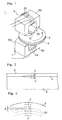
- Fig. 1 is a perspective view showing main parts of a magnetic transfer apparatus for executing a magnetic transfer method according to an embodiment of the present invention.
- Figs.2 and 3 are views showing definitions of the application angle of transferring magnetic field
- Fig.4 is a schematic view showing another embodiment of a magnetic field generating means
- Fig.5 is a schematic view showing principal steps of the magnetic transfer method according of the present invention. Note that each of the figures is a schematic view, and that dimension of each parts or the like shown therein is different from an actual dimension.
- a slave surface (magnetic recording surface) of a slave medium 2 (magnetic recording medium) is allowed to get in contact with an information bearing surface of a master medium 3 so that the slave medium and the master medium are in close contact with each other with predetermined pressing force after initial DC magnetization to be described later is executed.
- a transferring magnetic field is applied to them by a magnetic field generating means.
- magnetic patterns such as serv0o signal of the master medium 3 are transferred to the slave medium 2 to be recorded therein.
- the slave medium 2 is a disk type magnetic recording medium such as a hard disk, a flexible disk and the like which a magnetic recording layer is formed on both surfaces or one surface thereof.
- a cleaning process for removing micro protrusions or adhering particles on a surface of the slave medium by a grind head, abrasive substance and the like is executed, if desired, before the slave medium 2 and the master medium 3 are in close contact with each other.
- the slave medium 2 is allowed to previously undergo initial magnetization.
- This initial magnetization generates a magnetic field of magnetic field intensity distribution not less than the coercive force Hcs of the slave medium 2 in at least one place thereof in a tracking direction.
- such initial magnetization generates a magnetic field of magnetic field intensity distribution which is not less than the coercive force Hcs of the slave medium 2 only in the tracking direction and is less than the coercive force of the slave medium 2 in a direction reverse to the tracking direction in a portion of the tracking direction.
- the initial magnetization (DC demagnetization) of whole track is executed by rotating the slave medium 2 or the magnetic field in the tracking direction.
- the master medium 3 is formed into a disk shape. On one surface of the master medium 3, a transfer-information bearing surface on which micro uneven patterns due to a magnetic layer 32 are formed is formed (referring to Fig.5). The other surface of the master medium contrary to one surface is held to a close contact means (not shown) to be brought into close contact with a conveyed slave medium 2. As shown, there are a single surface sequential transfer in which the master medium 3 is brought into close contact with one surface of the slave medium 2 and a both surface simultaneous transfer in which the mater medium 3 is respectively brought into close contact with both surfaces of the slave medium 2. A cleaning process for removing micro particles adhered to the master medium 3 is performed, if necessary, before the master medium 3 and the slave medium 3 are in close contact with each other.
- a magnetic field generating means 5 electromagnet devices 50, 50, in which a coil 53 is wound on a core 52 having a gap 51 extending to the radial direction of the slave medium 2 and the master medium 3 held on a close contact means, are arranged on upper and lower sides of the mediums 2, 3.
- the magnetic field generating means 5 applies transferring magnetic field having magnetic lines G parallel to the tracking direction to the mediums 2, 3 in the same direction over and under the mediums 2, 3.
- a transferring magnetic field is applied by the magnetic field generating means and transfer information of the master medium 3 is magnetically transferred and recorded to a slave surface of the slave medium 2 while rotating integrally the slave medium 2 and the master medium 3. It is preferable that the magnetic field generating means 5 is rotatably mounted.
- the transferring magnetic field generates the magnetic field at a portion of the track direction, wherein the magnetic field has magnetic field intensity distribution that the magnetic field intensity greater than the maximum value of the range (0.6 ⁇ 1.3 times the coercive force Hcs of the slave medium) of the optimum transferring magnetic field intensity does not exist in any position of the track direction, and portion to be the magnetic field intensity within the range of the optimum transferring magnetic field intensity exists in at least one position in the single track direction, and the magnetic field intensity in the reverse track direction is less than the minimum value of the range of the optimum transferring magnetic field intensity in the whole positions of the track direction.
- the application angle of the transferring magnetic field by the magnetic field generating means 5 is within ⁇ 30° in the vertical direction with respect to the slave surface of the slave medium 2. That is, when seen from front as shown in Fig.2, an angle ⁇ between an application angle of the lines G of magnetic force of the transferring magnetic field generated in portions where the magnetic field is applied by the magnetic field generating means 5 and the slave surface F of the slave medium 2 in close contact with the master medium 3 is defined to be within ⁇ 30°. Also, in the figure, the upward angle ⁇ indicates a plus direction.
- the application angle of the transferring magnetic field is within ⁇ 30° with respect to the track direction on a plane parallel to the slave surface of the slave medium 2. That is, when seen from a plane direction as shown in Fig.3, an angle ⁇ between the application direction of lines G of the transferring magnetic field generated in portions where the magnetic field is applied by the magnetic field generating means 5 and a tangential direction of a circumferential track on the slave surface of the slave medium 2 is defined to be within ⁇ 30°. Also, in the figure, the outward angle ⁇ indicates a plus direction.
- sum of the absolute values of the angle ⁇ in the vertical direction and the angle ⁇ in the track direction is defined to be within 30°. The reason for such definition about the application angles of the transferring magnetic field will be described later.
- the magnetic field generating means 5 may be arranged in only one side. Also, in another embodiment, the electromagnet device or the permanent magnet device for generating the transferring magnetic field as shown in Fig. 4(A) ⁇ (C) may be arranged in only one side or both sides as the magnetic field generating means 5.
- the magnetic field generating means 5 shown in Fig. 4(A) is so constructed that both side portions, parallel to the slave surface, of one electromagnet 55 (or permanent magnet) extending in the radial direction of the slave medium 2 are made of opposite magnetic poles, to generate the magnetic field in the track direction.
- the magnetic field generating means 5 shown in Fig. 4(B) is so constructed that the end surfaces, toward the slave surface, of two parallel electromagnets 56, 57 (or permanent magnets) extending in the radial direction of the slave medium and spaced from each other at a predetermined gap are made of opposite magnetic poles, to generate the magnetic field in the track direction.
- 4(C) is so constructed that two parallel end surfaces, toward the slave surface, of the permanent magnet 58 (or electromagnet) having U shaped cross-sections and extending in the radial direction are made of opposite magnetic poles, to generate the magnetic field in the track direction.
- the angle ⁇ in the vertical direction and the angle ⁇ in the track direction in the application angles of the transferring magnetic field are defined to be within ⁇ 30°, respectively, and the sum of the absolute values of them is defined to be within 30°.
- Fig.5 is a schematic view showing basic patterns of the magnetic transfer.
- Fig. 5(A) shows a step of applying the magnetic field in one direction to initially D.C. magnetize the slave medium 2
- Fig. 5(B) shows a step of bring the master medium 3 and the slave medium 2 into close contact with each other and then applying magnetic field in a direction reverse to the one direction
- Fig. 5(C) shows a state after the magnetic transfer, respectively.
- the initial magnetic field Hin is applied to the slave medium 2 in one track direction to previously execute the initial magnetization (DC demagnetization).
- a slave surface (magnetic recording surface) of the slave medium 2 and an information bearing surface formed by coating micro uneven patterns on a substrate 31 of the master medium 3 with a magnetic layer 32 are in close contact with each other and then, the transferring magnetic field Hdu is applied to the slave medium 2 in a track direction reverse to the application direction of the initial magnetic direction, to thereby execute the magnetic transfer.
- magnetic patterns are transferred and recorded on the slave surface (track) of the slave medium 2 according to the patterns of protrusions and recesses of the magnetic layer 32 on the information-bearing surface of the master medium 3.
- the same magnetic patterns can be transferred and recorded by changing the direction of the initial magnetic field Hin and the direction of the transferring magnetic field Hdu to be directions reverse to the aforementioned directions.
- the magnetic transfer can be performed by means of only the substrate 31, so that the magnetic layer 32 need not be coated thereon.
- an excellent magnetic transfer can be performed by providing a magnetic layer 32 having good transfer property.
- the magnetic layer 32 of the master medium 3 is a soft magnetic layer having a coercive force Hcm of 48kA/m ( 600 Oe) or less.
- Nickel, silicon, quartz plate, glass, aluminum, alloy, ceramics, synthetic resin and the like are used as the substrate 31 of the master medium 3.
- the uneven patterns are formed with a stamper method, a photo-fabrication method and the like.
- photo-resist is formed on a glass plate (or quartz plate) having an even surface by a spin-coating and the like, a laser light (or electron beam) modulated according to the servo signal is irradiated on the glass plate while rotating the glass plate, and the whole photo-resist is exposed and thus predetermined patterns, for example, patterns corresponding to the servo signal and extending linearly in the radial direction on a line from a rotation center in each track, are formed in portions corresponding to the respective frames on the circumferences. Thereafter, the photo-resist is developed and the exposed portions are removed to obtain a disk having an uneven shape due to the photo-resist.
- plating electroforming
- This substrate may be used as a master medium in itself, or if necessary, a soft magnetic layer and a protective film may be coated on the uneven patterns to be used as a master medium.
- another plating may be performed on the disk again to make a second disk and another plating may be performed using the second disk to make a substrate having negative uneven patterns.
- a plating may be performed on the second disk or resin solution may be brought into close contact with the second disk and a curing be performed to make a third disk, and then another plating may be performed on the third disk to obtain a substrate having positive uneven patterns.
- a substrate may be made as described above.
- Ni or Ni alloy can be used as metal materials of the substrate, and various metal film growth methods such as non-electrolysis plating, electroforming, sputtering, ion plating and the like can be used in the plating for making the substrate.
- the depth of the uneven patterns (height of the protrusions) on the substrate is within a range of 80nm ⁇ 800nm and more preferably, within a range of 100nm ⁇ 600nm.
- the uneven patterns are formed long in the radial direction.
- the length in the radial direction is 0.05 ⁇ 20 ⁇ m, and that the length in the circumferential direction is 0.05 ⁇ 5 ⁇ m. It is preferable that within these ranges, patterns longer in the radial direction are preferably selected as patterns for bearing information of the servo signals.
- Formation of the magnetic layer 32 is executed by vacuum film growth method such as vacuum deposition method, sputtering method, ion-plating method, and plating method and the like.
- Co, Co alloy CoNi, CoNiZr, CoNbTaZr and the like
- Fe, Fe alloy Fe alloy (FeCo, FeCoNi, FeNiMo, FeAlSi, FeAl, FeTaN), Ni, Ni alloy (NiFe)
- FeCo, FeCoNi can be used as magnetic material of the magnetic layer.
- the thickness of the magnetic layer is within a range of 50 ⁇ 500nm and more preferably, within a range of 100 ⁇ 400nm.
- a protective film such as DLC is formed on the magnetic layer and a lubricant layer may be formed. More preferably, diamond-like-carbon (DLC) film of 5 ⁇ 30nm as protective film and the lubricant layer exist. Also, a contact-reinforcing layer such as Si may be formed between the magnetic layer and the protective film.
- the lubricant layer improves deterioration of durability such as generation of scars due to rubbing when correcting deviation generated during contacting with the slave medium.
- a resin substrate may be manufactured using the above disk and the magnetic layer may be formed thereon to be the master medium.
- Acryl resins such as poly carbonate and poly methyl methacrylate
- vinyl chloride resins such as poly vinyl chloride and vinyl chloride copolymer
- epoxy resins amorphous poly olefin, poly ester and the like
- Burrs on the formed product can be removed by means of vanishing or polishing.
- ultraviolet curable resin, electron beam curable resin and the like may be formed on the disk by means of spin coating or bar coating. It is preferable that the height of the protrusions on the resin substrate is within a range of 50 ⁇ 1000nm and more preferably, within a range of 100 ⁇ 500nm.
- the magnetic layer is coated on the micro patterns on the surface of the resin substrate to obtain the master medium.
- the magnetic layer is formed from the magnetic material by means of vacuum film growth method such as vacuum deposition method, sputtering method, ion plating method, and plating method and the like.
- photo-resist is coated on the flat surface of a flat substrate to form patterns according to information by exposure and development using a photo mask based on the patterns of the servo signals.
- the substrate is etched in according with patterns and formed with holes having a depth corresponding to the thickness of the magnetic layer by means of etching process.
- film growth material is coated up to the surface of the substrate in a thickness corresponding to the formed hole by means of vacuum film growth method such as vacuum deposition method, sputtering method, ion plating method, and plating method and the like.
- vacuum film growth method such as vacuum deposition method, sputtering method, ion plating method, and plating method and the like.
- the surface thereof is polished to remove burrs and to flatten.
- a magnetic recording medium having a disk shape such as a hard disk, high-density flexible disk and the like is used as the slave medium 2, and a coating type magnetic recording medium or a metal thin film type magnetic recording layer is formed as the magnetic recording layer.
- Co, Co alloy CoPtCr, CoCr, CoPtCrTa, CoPtCrNbTa, CoCrB, CoNi and the like
- Fe and Fe alloy FeCo, FePt, FeCoNi
- FeCo, FePt, FeCoNi can be used as a magnetic material of the metal thin film type magnetic recording layer. This is preferable because more accurate transfer can be performed in case that the magnetic flux density is greater and the magnetic anisotropy is shown in the same direction as the application direction of the magnetic field.
- nonmagnetic base layer is formed.
- the crystal structure and the lattice parameter should be mated with the magnetic layer.
- Cr, CrTi, CoCr, CrTa, CrMo, NiAl, Ru and the like can be used.
- the master medium, the slave medium and the magnetic transfer method used in the test are as following.
- Ni stamper method a Ni substrate having disk-shaped patterns of 0.2 ⁇ m depth was prepared, wherein the patterns have radial lines with equal interval and width of 0.5 ⁇ m within a range of 20 ⁇ 40mm from center of the disk to in the radial direction and the line interval is 0.5 ⁇ m at the innermost position which is 20mm distant radially from the center of the disk.
- a FeCo film soft magnetic layer having a thickness of 200nm was formed on the Ni substrate to be the master medium.
- the coercive force Hcm thereof was 8kA/M (100 Oe), and the magnetic flux density Ms was 28.9T (23000 Gauss).
- a glass plate was heated to 200°C to prepare a magnetic recording medium (hard disk) having a disk shape of 3.5inch type in which CrTi was 60nm thick, CoCrPt was 25nm thick, the magnetic flux density Ms was 5.7T (4500 Gauss) and the coercive force Hcs was 199kA/M (2500 Oe).
- a magnetic recording medium hard disk having a disk shape of 3.5inch type in which CrTi was 60nm thick, CoCrPt was 25nm thick, the magnetic flux density Ms was 5.7T (4500 Gauss) and the coercive force Hcs was 199kA/M (2500 Oe).
- the ring type head electromagnet shown in Fig. 1 was arranged so that the peak of the magnetic field intensity was 398kA/m (5000 Oe), which is 2 times the coercive force Hcs of the slave medium, on the surface of the slave medium, to initially DC magnetize the slave medium.
- the slave medium initially DC magnetized and the master medium was brought into close contact with each other and current of the ring type head electromagnet was regulated so that the peak of the magnetic field intensity was 207kA/m (2600 Oe) on the surface of the slave medium.
- the magnetic field was applied in a direction reverse to the application direction at the initial D.C. magnetization while the angle ⁇ in the vertical direction shown in Fig. 2 was varied in a range of 0° ⁇ ⁇ 45° and the angle ⁇ in the track direction shown in Fig. 3 was varied in a range of 0° ⁇ ⁇ 45°, to execute the magnet transfer. Also, close contact of the master medium and the slave medium was performed by means of pressing an aluminum plate with a rubber plate inserted.
- the transferring signal of the slave medium was evaluated by means of an apparatus for measuring electromagnet conversion property (SS-6 produced by Kyoto Denshi Ltd.).
- An MR head in which gap of a reproduction head was 0.24 ⁇ m, width of a reproduction track was 1.9 ⁇ m, gap of a recording head was 0.4 ⁇ m and width of a recording track was 2.4 ⁇ m was used as the head.
- the read-out signal was frequency-divided by a spectrum-analyzer and difference (C/N) between the peak intensity C of the first signal and noise N of the medium fitted from outside was measured.
- Table 1 shows values when the angle ⁇ and the angle ⁇ all were varied in plus directions
- Table 2 shows values when the angle ⁇ was varied in the plus direction and the angle ⁇ was varied in the plus direction.
- the plus direction of the angle ⁇ is the direction in which lines of magnetic force are inclined upward with respect to a close-contact surface of the slave medium and the master medium so as to proceed toward the slave medium, and the direction inclined downward is the minus direction.
- the plus direction of the angle ⁇ is the direction in which lines of magnetic force are inclined toward the outer circumference with respect to a tangent line of the track on the close contact surface of the slave medium and the master medium, and the direction inclined toward the inner circumference is the minus direction.
- data when the angle ⁇ in the plane track direction was varied is approximately equal to each other in the plus direction and in the minus direction, data in the minus direction were omitted.
Landscapes
- Manufacturing Of Magnetic Record Carriers (AREA)
- Magnetic Record Carriers (AREA)
Abstract

Description
- The present invention relates to a method and an apparatus for magnetically transferring magnetic information signals held in a master medium to a slave medium.
- The magnetic transfer method is one for magnetically transferring magnetic patterns corresponding to magnetic information (for example, servo signals) held in a master medium to a slave medium by applying transferring magnetic field in a state where the master medium and the slave medium are in close contact with each other. This magnetic transfer method is disclosed, for example, in Japanese Unexamined Patent Publication Nos. 63(1988)-183623, 10(1998)-40544, 10(1998)-269566 and the like.
- Moreover, transferring magnetic field is applied by arranging a magnetic field generating means such as an electromagnet device or a permanent magnet device to a single side or both sides of the slave medium in a state where the single side or both sides of the slave medium and the master medium are in close contact with each other. In this time, if the slave medium and the master medium that are in close contact with each other, or the magnetic field is relatively rotated, magnetic patterns are transferred to a track on a circumference of the slave medium of disk shape.
- However, in said magnetic transfer method, in order to enhance transfer accuracy by transferring magnetic patterns accurately corresponding to transfer information, in which a magnetic layer of uneven patterns was formed on an information bearing surface of the master medium to record them therein, to a recording surface of the slave medium, a transferring magnetic field should be accurately applied in a track direction in a state where the close contact property between an information bearing surface of the master medium and a slave surface of the slave medium is assured.
- However, it is difficult that magnetic field generated by an actual magnetic field generating means is made to be parallel to a track direction and a slave surface in a plane direction and a vertical direction from an inner circumference portion to a whole outer circumference portion of the slave medium, and is made to be offset due to various factors. If the offset of the application direction of such transferring magnetic field becomes greater, the magnetic transfer of high accuracy does not executed because the magnetic patterns of such area are scattered. Thus, when the transfer information is servo signals, a satisfactory tracking function cannot be obtained and reliability of reproducing the information is lowered.
- The present invention was made with the above-described problems in mind. The object of the present invention is to provide a method and an apparatus for magnetically transferring magnetic information signals held in a master medium to a slave medium in a state where the master medium and the slave medium are in close contact with each other, which is capable of executing accurate transfer of the magnetic patterns by defining the allowable range of the application direction of the transferring magnetic field.
- According to one aspect of the present invention, there is provided a magnetic transfer method for applying a transferring magnetic field in a state that a master medium for magnetically transferring in which a magnetic layer is formed in a portion corresponding to information signals on a surface of a substrate, and a magnetic recording medium which is a slave medium for being magnetically transferred, are in close contact with each other, comprising the steps of: applying a magnetic field to the slave medium in a track direction of a slave surface to initial DC magnetize the slave medium previously in the track direction; bringing the master medium and the slave medium into close contact with each other; and applying the transferring magnetic field in the track direction of a slave surface to execute a magnetic transfer, wherein an application angle of the transferring magnetic field is within a range of ± 30° in a vertical direction with respect to the slave surface.
- According to the other aspect of the present invention, there is provided a magnetic transfer method for applying a transferring magnetic field in a state that a master medium for magnetically transferring in which a magnetic layer is formed in a portion corresponding to information signals on a surface of a substrate, and a magnetic recording medium which is a slave medium for being magnetically transferred, are in close contact with each other, comprising the steps of: applying a magnetic field to the slave medium in a track direction of a slave surface to initial DC magnetize the slave medium previously in the track direction; bringing the master medium and the slave medium into close contact with each other; and applying the transferring magnetic field in the track direction of a slave surface to execute a magnetic transfer, wherein an application angle of the transferring magnetic field is within a range of ± 30° with respect to the track direction on a plane parallel to the slave.
- According to another aspect of the present invention, there is provided a magnetic transfer method for applying a transferring magnetic field in a state that a master medium for magnetically transferring in which a magnetic layer is formed in a portion corresponding to information signals on a surface of a substrate, and a magnetic recording medium which is a slave medium for being magnetically transferred, are in close contact with each other, comprising the steps of: applying a magnetic field to the slave medium in a track direction of a slave surface to initial DC magnetize the slave medium previously in the track direction; bringing the master medium and the slave medium into close contact with each other; and applying the transferring magnetic field in the track direction of a slave surface to execute a magnetic transfer, wherein a sum of absolute values of an application angle of the transferring magnetic field in a direction vertical to the slave surface and an application angle of the transferring magnetic field with respect to the track direction on a plane parallel to the slave surface is within 30°.
- According to another aspect of the present invention, there is provide a magnetic transfer apparatus for applying a transferring magnetic field in a state that a master medium for magnetically transferring in which a magnetic layer is formed in a portion corresponding to information signals on a surface of a substrate, and a magnetic recording medium which is a slave medium for being magnetically transferred, are in close contact with each other, which comprises: a magnetic field generating means for applying the transferring magnetic field to the slave medium in close contact with the master medium in a track direction, wherein an application angle of the transferring magnetic field by the magnetic field generating means is within a range of ± 30° in a vertical direction with respect to a slave surface and is within a range of ± 30° with respect to the track direction on a plane parallel to the slave surface.
- As the magnetic field generating means for applying the transferring magnetic field, an electromagnet device or a permanent magnet device can be used. However, the electromagnet device is preferably used because the conditions such as the magnetic field intensity and the like can be more easily set and regulated.
- There are a case that a single surface sequential transfer is executed by bringing the master medium into close contact with the single surface of the slave medium and a case that a both surfaces simultaneous transfer is executed by bringing the master mediums into close contact with both surfaces of the slave medium. At that time, the master medium is brought into close contact with the single surface or both surfaces of the slave medium and a magnetic field generating means is arranged in one side or both sides thereof to apply the transferring magnetic field thereto. The magnetic field generating means generates the magnetic field parallel to the track direction in a range extending in a radial direction of the slave medium, and the slave medium and the master medium in close contact with each other or the magnetic field generating means is relatively rotated, so that the magnetic pattern can be transferred to the whole surface of the slave medium having a disk shape.
- It is preferable that the slave medium is a disk-shaped magnetic recording medium such as a hard disk, a flexible disk and the like. It is also preferable that the magnetic layer of the master medium is magnetically transferred with the coercive force (Hcm) of 48kA/m ( 600 Oe) or less.
- It is preferable that in the above magnetic transfer method, fundamentally, the initial DC magnetization for DC magnetizing the slave medium in the track direction is first executed and the slave medium is brought into close contact with the master medium in which the magnetic layer is formed on the micro uneven patterns corresponding to the information to be transferred, and then the transferring magnetic field is applied in a direction reverse to the initial DC magnetization direction of the slave surface to execute the magnetic transfer. It is preferable that the information is a servo signal.
- The initial magnetization of the slave medium is executed by generating the magnetic field at a portion of the track direction, and rotating the slave medium or the magnetic field in the track direction, wherein the magnetic field has magnetic field intensity distribution having portions of the magnetic field intensity not less than the coercive force of the slave medium in at least one position of the track direction. Also, it is preferable to generate the magnetic field at a portion of the track direction, of which magnetic field intensity distribution has the portions of the magnetic field intensity not less than the coercive force of the slave medium only in a single directional position of the track direction and has the magnetic field intensity in the reverse direction less than the coercive force of the slave medium in the whole positions of the track direction.
- Also, it is preferable that application of the transferring magnetic field is executed by generating the magnetic field at a portion of the track direction, and rotating the master medium for the magnetic transfer and the slave medium initially DC magnetized in close contact with each other, or the magnetic field in the track direction, wherein the magnetic field has magnetic field intensity distribution that the magnetic field intensity greater than the maximum value of the range of the optimum transferring magnetic field intensity does not exist in any position of the track direction, portion to be the magnetic field intensity within the range of the optimum transferring magnetic field intensity exists in at least one position in the single track direction, and the magnetic field intensity in the reverse track direction is less than the minimum value of the range of the optimum transferring magnetic field intensity in the whole positions of the track direction. The range of the optimum transferring magnetic field intensity is 0.6∼1.3 times the coercive force (Hcs) of the slave medium.
- According to the aforementioned present invention, because when executing the magnetic transfer, the application angle of the transferring magnetic field is within a range of ± 30° in a vertical direction with respect to the slave surface, or the application angle of the transferring magnetic field is within a range of ± 30° with respect to the track direction on a plane parallel to the slave surface, or sum of absolute values of an application angle of the transferring magnetic field in a direction vertical to the slave surface and an application angle of the transferring magnetic field with respect to the track direction on a plane parallel to the slave surface is within 30°, an accurate transfer of the magnetic patterns can be executed with homogeneous properties on the whole surface of the slave medium and can assure an excellent tracking function in a case of servo signals to improve reliability thereof.
- In constructing the magnetic transfer device, by regulating the application angle of the magnetic field for magnetic transfer within an allowable range as described above, an excellent magnetic transfer can be executed, so that design of accuracy in assembly of the whole device, intensity and distribution of the magnetic field in the magnetic field generating means and the like is easily performed.
- The embodiments of the present invention will be explained with reference to the accompanying drawings, in which:
- Fig.1 is a perspective view showing main parts of a magnetic transfer apparatus for executing a magnetic transfer method according to an embodiment of the present invention;
- Fig.2 is a front view showing a first definition of application angle of transferring magnetic field;
- Fig.3 is a plan view showing a second definition of application angle of transferring magnetic field;
- Fig.4 is a schematic view showing another embodiment of a magnetic field generating means; and
- Fig.5 is a schematic view showing principal steps of the magnetic transfer method according of the present invention.
-
- Hereinbelow, description will be given for embodiments of the present invention in detail with reference to the accompanying drawings.
- Fig. 1 is a perspective view showing main parts of a magnetic transfer apparatus for executing a magnetic transfer method according to an embodiment of the present invention. Figs.2 and 3 are views showing definitions of the application angle of transferring magnetic field, Fig.4 is a schematic view showing another embodiment of a magnetic field generating means, and Fig.5 is a schematic view showing principal steps of the magnetic transfer method according of the present invention. Note that each of the figures is a schematic view, and that dimension of each parts or the like shown therein is different from an actual dimension.
- In the magnetic transfer apparatus of Fig.1, during the magnetic transfer, a slave surface (magnetic recording surface) of a slave medium 2 (magnetic recording medium) is allowed to get in contact with an information bearing surface of a
master medium 3 so that the slave medium and the master medium are in close contact with each other with predetermined pressing force after initial DC magnetization to be described later is executed. In this close contact state between theslave medium 2 and themaster medium 3, a transferring magnetic field is applied to them by a magnetic field generating means. Thus, magnetic patterns such as serv0o signal of themaster medium 3 are transferred to theslave medium 2 to be recorded therein. - The
slave medium 2 is a disk type magnetic recording medium such as a hard disk, a flexible disk and the like which a magnetic recording layer is formed on both surfaces or one surface thereof. A cleaning process for removing micro protrusions or adhering particles on a surface of the slave medium by a grind head, abrasive substance and the like is executed, if desired, before theslave medium 2 and themaster medium 3 are in close contact with each other. - Moreover, the
slave medium 2 is allowed to previously undergo initial magnetization. This initial magnetization generates a magnetic field of magnetic field intensity distribution not less than the coercive force Hcs of theslave medium 2 in at least one place thereof in a tracking direction. Preferably, such initial magnetization generates a magnetic field of magnetic field intensity distribution which is not less than the coercive force Hcs of theslave medium 2 only in the tracking direction and is less than the coercive force of theslave medium 2 in a direction reverse to the tracking direction in a portion of the tracking direction. Thus, the initial magnetization (DC demagnetization) of whole track is executed by rotating theslave medium 2 or the magnetic field in the tracking direction. - The
master medium 3 is formed into a disk shape. On one surface of themaster medium 3, a transfer-information bearing surface on which micro uneven patterns due to amagnetic layer 32 are formed is formed (referring to Fig.5). The other surface of the master medium contrary to one surface is held to a close contact means (not shown) to be brought into close contact with a conveyedslave medium 2. As shown, there are a single surface sequential transfer in which themaster medium 3 is brought into close contact with one surface of theslave medium 2 and a both surface simultaneous transfer in which themater medium 3 is respectively brought into close contact with both surfaces of theslave medium 2. A cleaning process for removing micro particles adhered to themaster medium 3 is performed, if necessary, before themaster medium 3 and theslave medium 3 are in close contact with each other. - In a magnetic field generating means 5,
electromagnet devices coil 53 is wound on acore 52 having agap 51 extending to the radial direction of theslave medium 2 and themaster medium 3 held on a close contact means, are arranged on upper and lower sides of themediums mediums mediums - During the magnetic field application, a transferring magnetic field is applied by the magnetic field generating means and transfer information of the
master medium 3 is magnetically transferred and recorded to a slave surface of theslave medium 2 while rotating integrally theslave medium 2 and themaster medium 3. It is preferable that the magnetic field generating means 5 is rotatably mounted. - The transferring magnetic field generates the magnetic field at a portion of the track direction, wherein the magnetic field has magnetic field intensity distribution that the magnetic field intensity greater than the maximum value of the range (0.6∼1.3 times the coercive force Hcs of the slave medium) of the optimum transferring magnetic field intensity does not exist in any position of the track direction, and portion to be the magnetic field intensity within the range of the optimum transferring magnetic field intensity exists in at least one position in the single track direction, and the magnetic field intensity in the reverse track direction is less than the minimum value of the range of the optimum transferring magnetic field intensity in the whole positions of the track direction.
- When executing the magnetic transfer, the application angle of the transferring magnetic field by the magnetic field generating means 5 is within ± 30° in the vertical direction with respect to the slave surface of the
slave medium 2. That is, when seen from front as shown in Fig.2, an angle α between an application angle of the lines G of magnetic force of the transferring magnetic field generated in portions where the magnetic field is applied by the magnetic field generating means 5 and the slave surface F of theslave medium 2 in close contact with themaster medium 3 is defined to be within ±30°. Also, in the figure, the upward angle α indicates a plus direction. - Also, the application angle of the transferring magnetic field is within ± 30° with respect to the track direction on a plane parallel to the slave surface of the
slave medium 2. That is, when seen from a plane direction as shown in Fig.3, an angle β between the application direction of lines G of the transferring magnetic field generated in portions where the magnetic field is applied by the magnetic field generating means 5 and a tangential direction of a circumferential track on the slave surface of theslave medium 2 is defined to be within ± 30°. Also, in the figure, the outward angle β indicates a plus direction. - Also, in the application angle of the transferring magnetic field, sum of the absolute values of the angle α in the vertical direction and the angle β in the track direction is defined to be within 30°. The reason for such definition about the application angles of the transferring magnetic field will be described later.
- The magnetic field generating means 5 may be arranged in only one side. Also, in another embodiment, the electromagnet device or the permanent magnet device for generating the transferring magnetic field as shown in Fig. 4(A)∼(C) may be arranged in only one side or both sides as the magnetic field generating means 5.
- The magnetic field generating means 5 shown in Fig. 4(A) is so constructed that both side portions, parallel to the slave surface, of one electromagnet 55 (or permanent magnet) extending in the radial direction of the
slave medium 2 are made of opposite magnetic poles, to generate the magnetic field in the track direction. The magnetic field generating means 5 shown in Fig. 4(B) is so constructed that the end surfaces, toward the slave surface, of twoparallel electromagnets 56, 57 (or permanent magnets) extending in the radial direction of the slave medium and spaced from each other at a predetermined gap are made of opposite magnetic poles, to generate the magnetic field in the track direction. The magnetic field generating means 5 shown in Fig. 4(C) is so constructed that two parallel end surfaces, toward the slave surface, of the permanent magnet 58 (or electromagnet) having U shaped cross-sections and extending in the radial direction are made of opposite magnetic poles, to generate the magnetic field in the track direction. - Also, in the magnetic field generating means 5 of the respective embodiments as described above, the angle α in the vertical direction and the angle β in the track direction in the application angles of the transferring magnetic field are defined to be within ±30°, respectively, and the sum of the absolute values of them is defined to be within 30°.
- Next, Fig.5 is a schematic view showing basic patterns of the magnetic transfer. Fig. 5(A) shows a step of applying the magnetic field in one direction to initially D.C. magnetize the
slave medium 2, Fig. 5(B) shows a step of bring themaster medium 3 and theslave medium 2 into close contact with each other and then applying magnetic field in a direction reverse to the one direction, and Fig. 5(C) shows a state after the magnetic transfer, respectively. - First, as shown in Fig. 5(A), the initial magnetic field Hin is applied to the
slave medium 2 in one track direction to previously execute the initial magnetization (DC demagnetization). Then, as shown in Fig. 5(B), a slave surface (magnetic recording surface) of theslave medium 2 and an information bearing surface formed by coating micro uneven patterns on asubstrate 31 of themaster medium 3 with amagnetic layer 32 are in close contact with each other and then, the transferring magnetic field Hdu is applied to theslave medium 2 in a track direction reverse to the application direction of the initial magnetic direction, to thereby execute the magnetic transfer. As a result, as shown in Fig. 5(C), magnetic patterns are transferred and recorded on the slave surface (track) of theslave medium 2 according to the patterns of protrusions and recesses of themagnetic layer 32 on the information-bearing surface of themaster medium 3. - Also, even when the uneven patterns on the
substrate 31 of themaster medium 3 are negative patterns having uneven shapes reverse to the positive patterns in Fig. 5, the same magnetic patterns can be transferred and recorded by changing the direction of the initial magnetic field Hin and the direction of the transferring magnetic field Hdu to be directions reverse to the aforementioned directions. - When the
substrate 31 is made of ferromagnetic substance such as Ni and the like, the magnetic transfer can be performed by means of only thesubstrate 31, so that themagnetic layer 32 need not be coated thereon. However, an excellent magnetic transfer can be performed by providing amagnetic layer 32 having good transfer property. When thesubstrate 31 is made of nonmagnetic substance, themagnetic layer 32 needs to be provided. It is preferable that themagnetic layer 32 of themaster medium 3 is a soft magnetic layer having a coercive force Hcm of 48kA/m ( 600 Oe) or less. - Nickel, silicon, quartz plate, glass, aluminum, alloy, ceramics, synthetic resin and the like are used as the
substrate 31 of themaster medium 3. The uneven patterns are formed with a stamper method, a photo-fabrication method and the like. - In the stamper method, photo-resist is formed on a glass plate (or quartz plate) having an even surface by a spin-coating and the like, a laser light (or electron beam) modulated according to the servo signal is irradiated on the glass plate while rotating the glass plate, and the whole photo-resist is exposed and thus predetermined patterns, for example, patterns corresponding to the servo signal and extending linearly in the radial direction on a line from a rotation center in each track, are formed in portions corresponding to the respective frames on the circumferences. Thereafter, the photo-resist is developed and the exposed portions are removed to obtain a disk having an uneven shape due to the photo-resist. Next, based on the uneven patterns on the surface of the disk, plating (electroforming) is performed on the surface to obtain a Ni substrate having positive uneven patterns, and then the Ni substrate is removed from the disk. This substrate may be used as a master medium in itself, or if necessary, a soft magnetic layer and a protective film may be coated on the uneven patterns to be used as a master medium.
- Also, another plating may be performed on the disk again to make a second disk and another plating may be performed using the second disk to make a substrate having negative uneven patterns. Also, a plating may be performed on the second disk or resin solution may be brought into close contact with the second disk and a curing be performed to make a third disk, and then another plating may be performed on the third disk to obtain a substrate having positive uneven patterns.
- On the other hand, after patterns due to the photo-resist are formed on the glass plate, holes are formed in the glass plate by etching and the photo-resist is removed to obtain a disk, and then a substrate may be made as described above.
- Ni or Ni alloy can be used as metal materials of the substrate, and various metal film growth methods such as non-electrolysis plating, electroforming, sputtering, ion plating and the like can be used in the plating for making the substrate. It is preferable that the depth of the uneven patterns (height of the protrusions) on the substrate is within a range of 80nm ∼ 800nm and more preferably, within a range of 100nm ∼ 600nm. In a case of servo signals, the uneven patterns are formed long in the radial direction. For example, it is preferable that the length in the radial direction is 0.05 ∼ 20µm, and that the length in the circumferential direction is 0.05 ∼ 5µm. It is preferable that within these ranges, patterns longer in the radial direction are preferably selected as patterns for bearing information of the servo signals.
- Formation of the magnetic layer 32 (soft magnetic layer) is executed by vacuum film growth method such as vacuum deposition method, sputtering method, ion-plating method, and plating method and the like. Co, Co alloy (CoNi, CoNiZr, CoNbTaZr and the like), Fe, Fe alloy (FeCo, FeCoNi, FeNiMo, FeAlSi, FeAl, FeTaN), Ni, Ni alloy (NiFe) can be used as magnetic material of the magnetic layer. Preferably, FeCo, FeCoNi can be used. It is preferable that the thickness of the magnetic layer is within a range of 50 ∼ 500nm and more preferably, within a range of 100 ∼ 400nm.
- Also, it is preferable that a protective film such as DLC is formed on the magnetic layer and a lubricant layer may be formed. More preferably, diamond-like-carbon (DLC) film of 5 ∼ 30nm as protective film and the lubricant layer exist. Also, a contact-reinforcing layer such as Si may be formed between the magnetic layer and the protective film. The lubricant layer improves deterioration of durability such as generation of scars due to rubbing when correcting deviation generated during contacting with the slave medium.
- A resin substrate may be manufactured using the above disk and the magnetic layer may be formed thereon to be the master medium. Acryl resins such as poly carbonate and poly methyl methacrylate, vinyl chloride resins such as poly vinyl chloride and vinyl chloride copolymer, epoxy resins, amorphous poly olefin, poly ester and the like can be used as the resin material of the resin substrate. From the point of view of moisture proof property, dimensions stability, price and the like, polycarbonate is preferable. Burrs on the formed product can be removed by means of vanishing or polishing. Also, ultraviolet curable resin, electron beam curable resin and the like may be formed on the disk by means of spin coating or bar coating. It is preferable that the height of the protrusions on the resin substrate is within a range of 50 ∼ 1000nm and more preferably, within a range of 100 ∼ 500nm.
- The magnetic layer is coated on the micro patterns on the surface of the resin substrate to obtain the master medium. The magnetic layer is formed from the magnetic material by means of vacuum film growth method such as vacuum deposition method, sputtering method, ion plating method, and plating method and the like.
- On the other hand, in the photo-fabrication method, for example, photo-resist is coated on the flat surface of a flat substrate to form patterns according to information by exposure and development using a photo mask based on the patterns of the servo signals. Subsequently, the substrate is etched in according with patterns and formed with holes having a depth corresponding to the thickness of the magnetic layer by means of etching process. Subsequently, film growth material is coated up to the surface of the substrate in a thickness corresponding to the formed hole by means of vacuum film growth method such as vacuum deposition method, sputtering method, ion plating method, and plating method and the like. Subsequently, the surface thereof is polished to remove burrs and to flatten.
- A magnetic recording medium having a disk shape such as a hard disk, high-density flexible disk and the like is used as the
slave medium 2, and a coating type magnetic recording medium or a metal thin film type magnetic recording layer is formed as the magnetic recording layer. Co, Co alloy (CoPtCr, CoCr, CoPtCrTa, CoPtCrNbTa, CoCrB, CoNi and the like), Fe and Fe alloy (FeCo, FePt, FeCoNi) can be used as a magnetic material of the metal thin film type magnetic recording layer. This is preferable because more accurate transfer can be performed in case that the magnetic flux density is greater and the magnetic anisotropy is shown in the same direction as the application direction of the magnetic field. In order to provide the required magnetic anisotropy under (support member side) the magnetic material, it is preferable that nonmagnetic base layer is formed. The crystal structure and the lattice parameter should be mated with the magnetic layer. For that, Cr, CrTi, CoCr, CrTa, CrMo, NiAl, Ru and the like can be used. - Now, the result of test executed with the application direction of the transferring magnetic field within the aforementioned range will be explained. The master medium, the slave medium and the magnetic transfer method used in the test are as following.
- By Ni stamper method, a Ni substrate having disk-shaped patterns of 0.2µm depth was prepared, wherein the patterns have radial lines with equal interval and width of 0.5µm within a range of 20 ∼ 40mm from center of the disk to in the radial direction and the line interval is 0.5µm at the innermost position which is 20mm distant radially from the center of the disk. In the vacuum film growth apparatus, under conditions that pressure was decreased to 1.33 × 10⁻⁵Pa(10-7 Torr) at room temperature and then argon gas was introduced to be 0.4Pa(3 × 10⁻³ Torr), a FeCo film (soft magnetic layer) having a thickness of 200nm was formed on the Ni substrate to be the master medium. The coercive force Hcm thereof was 8kA/M (100 Oe), and the magnetic flux density Ms was 28.9T (23000 Gauss).
- In the vacuum film growth apparatus, under conditions that pressure was decreased to 1.33 × 10⁻⁵Pa(10-7Torr) at room temperature and then argon gas was introduced to be 0.4Pa(3 × 10⁻³Torr), a glass plate was heated to 200°C to prepare a magnetic recording medium (hard disk) having a disk shape of 3.5inch type in which CrTi was 60nm thick, CoCrPt was 25nm thick, the magnetic flux density Ms was 5.7T (4500 Gauss) and the coercive force Hcs was 199kA/M (2500 Oe).
- The ring type head electromagnet shown in Fig. 1 was arranged so that the peak of the magnetic field intensity was 398kA/m (5000 Oe), which is 2 times the coercive force Hcs of the slave medium, on the surface of the slave medium, to initially DC magnetize the slave medium. Next, the slave medium initially DC magnetized and the master medium was brought into close contact with each other and current of the ring type head electromagnet was regulated so that the peak of the magnetic field intensity was 207kA/m (2600 Oe) on the surface of the slave medium.
- In the application angle of the magnetic field (peak magnetic field) by the upper and lower electromagnets, the magnetic field was applied in a direction reverse to the application direction at the initial D.C. magnetization while the angle α in the vertical direction shown in Fig. 2 was varied in a range of 0° ∼ ±45° and the angle β in the track direction shown in Fig. 3 was varied in a range of 0° ∼ ±45°, to execute the magnet transfer. Also, close contact of the master medium and the slave medium was performed by means of pressing an aluminum plate with a rubber plate inserted.
- The transferring signal of the slave medium was evaluated by means of an apparatus for measuring electromagnet conversion property (SS-6 produced by Kyoto Denshi Ltd.). An MR head in which gap of a reproduction head was 0.24µm, width of a reproduction track was 1.9µm, gap of a recording head was 0.4µm and width of a recording track was 2.4µm was used as the head. The read-out signal was frequency-divided by a spectrum-analyzer and difference (C/N) between the peak intensity C of the first signal and noise N of the medium fitted from outside was measured. The relative value ΔC/N was evaluated while the value when the angle α and the angle β were all 0° (that is, α=β=0°) was 0dB. Because when the relative value ΔC/N got less than -6dB (greater in the minus direction), the signal intensity was small and the transfer got bad, the value was evaluated as a permitted value. The result is shown in table 1 and table 2.
β C/N (dB) 45° -9.2 -9.5 -9.6 -10.0 -10.3 -10.7 -11.1 -13.8 -17.1 -19.6 40° -8.1 -8.9 -9.1 -8.9 -9.1 -9.7 -10.5 -12.5 -14.1 -16.9 35° -6.3 -7.7 -7.4 -8.7 -8.9 -9.1 -9.5 -10.9 -13.5 -14.7 30° -2.7 -7.1 -7.1 -8.3 -8.7 -8.5 -9.1 -9.7 -13.1 -14.5 25° -1.9 -2.7 -6.5 -7.1 -8.1 -8.4 -8.9 -11.1 -12.7 -14.1 20° -1.3 -1.7 -2.7 -6.8 -7.8 -8.1 -8.5 -9.1 -9.5 -10.4 15° -0.5 -1.2 -1.9 -2.7 -7.1 -7.5 -8.1 -8.3 -8.9 -9.1 10° -0.2 -0.4 -1.5 -1.9 -2.8 -6.4 -7.4 -7.9 -8.3 -8.9 5° -0.1 -0.2 -0.7 -1.8 -2.1 -2.5 -6.9 -7.1 -8.1 -8.7 0° 0 -0.2 -0.2 -0.9 -1.5 -2.1 -2.8 -6.7 -7.2 -8.5 0° 5° 10° 15° 20° 25° 30° 35° 40° 45° α β C/N (dB) 45° -9.3 -9.7 -10.1 -10.5 -10.8 -11.2 -11.3 -14.3 -17.4 -19.1 40° -8.7 -9.1 -8.9 -9.5 -9.9 -10.1 -10.8 -11.9 -15.1 -17.6 35° -7.1 -8.7 -8.6 -9.1 -9.3 -9.7 -10.1 -11.3 -11.9 -13.8 30° -2.8 -7.9 -8.3 -8.1 -8.4 -8.3 -9.3 -9.7 -10.5 -11.1 25° -2.1 -2.8 -6.9 -7.1 -7.4 -7.9 -8.1 -9.8 -9.9 -10.8 20° -1.5 -2.4 -3.0 -6.3 -6.8 -7.4 -7.9 -8.9 -9.1 -9.5 15° -0.9 -1.4 -1.6 -2.7 -6.4 -6.7 -7.5 -8.2 -8.8 -9.6 10° -0.3 -0.5 -0.9 -2.5 -3.1 -6.7 -7.3 -7.7 -8.5 -9.1 5° -0.1 -0.3 -0.4 -2.1 -2.3 -3.1 -6.7 -7.1 -7.9 -8.4 0° 0 -0.1 -0.3 -1.0 -1.9 -2.1 -2.7 -7.0 -7.9 -8.8 -0° -5° -10° -15° -20° -25° -30° -35° -40° -45° α - Also, Table 1 shows values when the angle α and the angle β all were varied in plus directions, and Table 2 shows values when the angle α was varied in the plus direction and the angle β was varied in the plus direction. The plus direction of the angle α is the direction in which lines of magnetic force are inclined upward with respect to a close-contact surface of the slave medium and the master medium so as to proceed toward the slave medium, and the direction inclined downward is the minus direction. The plus direction of the angle β is the direction in which lines of magnetic force are inclined toward the outer circumference with respect to a tangent line of the track on the close contact surface of the slave medium and the master medium, and the direction inclined toward the inner circumference is the minus direction. Also, because data when the angle β in the plane track direction was varied is approximately equal to each other in the plus direction and in the minus direction, data in the minus direction were omitted.
- As shown in Table 1 and Table 2, when the angle β was 0°, good magnetic transfer could be performed if the angle α was within a range of +30° ∼ - 30°. Similarly, when the angle α was 0°, good magnetic transfer could be performed if the angle β was within a range of +30° ∼ -30° (minus values were not shown but were equal to plus values). Also, when any one of the angle α and the angle β got greater in the plus direction or the minus direction, a good range of the relative value ΔC/N was in a range in which absolute value of the other one was smaller than 30°. A good magnetic transfer could be performed within a range surrounded with a thick ruled line in which sum of the absolute values of both angles α and β was smaller than 30°.
Claims (4)
- A magnetic transfer method for applying a transferring magnetic field in a state that a master medium for magnetically transferring in which a magnetic layer is formed in a portion corresponding to information signals on a surface of a substrate, and a magnetic recording medium which is a slave medium for being magnetically transferred, are in close contact with each other, comprising the steps of:wherein an application angle of the transferring magnetic field is within a range of ± 30° in a vertical direction with respect to the slave surface.applying a magnetic field to the slave medium in a track direction of a slave surface to initial DC magnetize the slave medium previously in the track direction;bringing the master medium and the slave medium into close contact with each other; andapplying the transferring magnetic field in the track direction of a slave surface to execute a magnetic transfer,
- A magnetic transfer method for applying a transferring magnetic field in a state that a master medium for magnetically transferring in which a magnetic layer is formed in a portion corresponding to information signals on a surface of a substrate, and a magnetic recording medium which is a slave medium for being magnetically transferred, are in close contact with each other, comprising the steps of:wherein an application angle of the transferring magnetic field is within a range of ± 30° with respect to the track direction on a plane parallel to the slave.applying a magnetic field to the slave medium in a track direction of a slave surface to initial DC magnetize the slave medium previously in the track direction;bringing the master medium and the slave medium into close contact with each other; andapplying the transferring magnetic field in the track direction of a slave surface to execute a magnetic transfer,
- A magnetic transfer method for applying a transferring magnetic field in a state that a master medium for magnetically transferring in which a magnetic layer is formed in a portion corresponding to information signals on a surface of a substrate, and a magnetic recording medium which is a slave medium for being magnetically transferred, are in close contact with each other, comprising the steps of:wherein a sum of absolute values of an application angle of the transferring magnetic field in a direction vertical to the slave surface and an application angle of the transferring magnetic field with respect to the track direction on a plane parallel to the slave surface is within 30°.applying a magnetic field to the slave medium in a track direction of a slave surface to initial DC magnetize the slave medium previously in the track direction;bringing the master medium and the slave medium into close contact with each other; andapplying the transferring magnetic field in the track direction of a slave surface to execute a magnetic transfer,
- A magnetic transfer apparatus for applying a transferring magnetic field in a state that a master medium for magnetically transferring in which a magnetic layer is formed in a portion corresponding to information signals on a surface of a substrate, and a magnetic recording medium which is a slave medium for being magnetically transferred, are in close contact with each other, which comprises:wherein an application angle of the transferring magnetic field by the magnetic field generating means is within a range of ± 30° in a vertical direction with respect to a slave surface and is within a range of ± 30° with respect to the track direction on a plane parallel to the slave surface.a magnetic field generating means for applying the transferring magnetic field to the slave medium in close contact with the master medium in a track direction,
Applications Claiming Priority (2)
| Application Number | Priority Date | Filing Date | Title |
|---|---|---|---|
| JP2001047809A JP4046480B2 (en) | 2001-02-23 | 2001-02-23 | Magnetic transfer method and magnetic transfer apparatus |
| JP2001047809 | 2001-02-23 |
Publications (2)
| Publication Number | Publication Date |
|---|---|
| EP1235207A2 true EP1235207A2 (en) | 2002-08-28 |
| EP1235207A3 EP1235207A3 (en) | 2007-10-24 |
Family
ID=18909164
Family Applications (1)
| Application Number | Title | Priority Date | Filing Date |
|---|---|---|---|
| EP02003193A Withdrawn EP1235207A3 (en) | 2001-02-23 | 2002-02-18 | Method and apparatus of magnetically transferring information signal from master medium to slave medium |
Country Status (6)
| Country | Link |
|---|---|
| US (1) | US7139140B2 (en) |
| EP (1) | EP1235207A3 (en) |
| JP (1) | JP4046480B2 (en) |
| KR (1) | KR20020069135A (en) |
| CN (1) | CN1219285C (en) |
| SG (1) | SG116440A1 (en) |
Families Citing this family (4)
| Publication number | Priority date | Publication date | Assignee | Title |
|---|---|---|---|---|
| US20020187295A1 (en) * | 2001-05-15 | 2002-12-12 | Fuji Photo Film Co., Ltd. | Magnetic transfer master medium |
| US7440207B2 (en) * | 2004-10-13 | 2008-10-21 | Fujifilm Corporation | Magnetic-transfer method, magnetic recording medium, and magnetic recording device |
| JP2007293964A (en) * | 2006-04-24 | 2007-11-08 | Hitachi Global Storage Technologies Netherlands Bv | Degaussing device and degaussing method for magnetic disk |
| JP5238290B2 (en) * | 2008-02-28 | 2013-07-17 | 昭和電工株式会社 | Method for manufacturing magnetic recording medium |
Citations (7)
| Publication number | Priority date | Publication date | Assignee | Title |
|---|---|---|---|---|
| JPS56143543A (en) * | 1980-04-09 | 1981-11-09 | Matsushita Electric Ind Co Ltd | Magnetic tape transfer system |
| JPS57109134A (en) * | 1980-12-26 | 1982-07-07 | Toshiba Corp | Magnetic transferring and recording method |
| JPS57138061A (en) * | 1981-02-17 | 1982-08-26 | Matsushita Electric Ind Co Ltd | Magnetic transferring system |
| US5796533A (en) * | 1994-03-15 | 1998-08-18 | Kao Corporation | System for magnetic contact duplication |
| EP0915456A1 (en) * | 1996-07-22 | 1999-05-12 | Matsushita Electric Industrial Co., Ltd | Master information carrier, process for producing the carrier, and method and apparatus for recording master information signal on magnetic recording medium by using the carrier |
| US5991104A (en) * | 1996-11-27 | 1999-11-23 | Seagate Technology, Inc. | Using servowriter medium for quickly written servo-patterns on magnetic media |
| WO2000026904A1 (en) * | 1998-10-29 | 2000-05-11 | Matsushita Electric Industrial Co., Ltd. | Master information medium and method of master information recording |
Family Cites Families (4)
| Publication number | Priority date | Publication date | Assignee | Title |
|---|---|---|---|---|
| US5229983A (en) * | 1989-12-28 | 1993-07-20 | Matsushita Electric Industrial Co., Ltd. | Bias magnetic field generating apparatus for magneto-optical recording and reproducing system |
| JPH0652545A (en) * | 1992-07-31 | 1994-02-25 | Sony Corp | Magnetic transferring method and magnetic recording method for digital image signal |
| US6433944B1 (en) * | 1998-09-25 | 2002-08-13 | Fuji Photo Film Co., Ltd. | Master carrier for magnetic transfer and method for transfer |
| US6570724B1 (en) * | 1999-04-26 | 2003-05-27 | Fuji Photo Film Co., Ltd. | Method and apparatus for magnetic transfer |
-
2001
- 2001-02-23 JP JP2001047809A patent/JP4046480B2/en not_active Expired - Fee Related
-
2002
- 2002-02-18 EP EP02003193A patent/EP1235207A3/en not_active Withdrawn
- 2002-02-19 SG SG200200898A patent/SG116440A1/en unknown
- 2002-02-21 KR KR1020020009219A patent/KR20020069135A/en not_active Application Discontinuation
- 2002-02-21 US US10/078,535 patent/US7139140B2/en not_active Expired - Fee Related
- 2002-02-25 CN CNB021052824A patent/CN1219285C/en not_active Expired - Fee Related
Patent Citations (7)
| Publication number | Priority date | Publication date | Assignee | Title |
|---|---|---|---|---|
| JPS56143543A (en) * | 1980-04-09 | 1981-11-09 | Matsushita Electric Ind Co Ltd | Magnetic tape transfer system |
| JPS57109134A (en) * | 1980-12-26 | 1982-07-07 | Toshiba Corp | Magnetic transferring and recording method |
| JPS57138061A (en) * | 1981-02-17 | 1982-08-26 | Matsushita Electric Ind Co Ltd | Magnetic transferring system |
| US5796533A (en) * | 1994-03-15 | 1998-08-18 | Kao Corporation | System for magnetic contact duplication |
| EP0915456A1 (en) * | 1996-07-22 | 1999-05-12 | Matsushita Electric Industrial Co., Ltd | Master information carrier, process for producing the carrier, and method and apparatus for recording master information signal on magnetic recording medium by using the carrier |
| US5991104A (en) * | 1996-11-27 | 1999-11-23 | Seagate Technology, Inc. | Using servowriter medium for quickly written servo-patterns on magnetic media |
| WO2000026904A1 (en) * | 1998-10-29 | 2000-05-11 | Matsushita Electric Industrial Co., Ltd. | Master information medium and method of master information recording |
Also Published As
| Publication number | Publication date |
|---|---|
| US7139140B2 (en) | 2006-11-21 |
| SG116440A1 (en) | 2005-11-28 |
| US20020163747A1 (en) | 2002-11-07 |
| JP4046480B2 (en) | 2008-02-13 |
| KR20020069135A (en) | 2002-08-29 |
| JP2002251723A (en) | 2002-09-06 |
| CN1219285C (en) | 2005-09-14 |
| CN1374642A (en) | 2002-10-16 |
| EP1235207A3 (en) | 2007-10-24 |
Similar Documents
| Publication | Publication Date | Title |
|---|---|---|
| JP3999436B2 (en) | Master carrier for magnetic transfer | |
| US7199953B2 (en) | Magnetic transfer master medium, magnetic transfer method, and magnetic transfer master medium forming method | |
| KR20020086291A (en) | Master carrier for magnetic transfer | |
| US6804069B2 (en) | Magnetic transfer method to prevent dropout of servo signal | |
| KR20030043747A (en) | Master carrier for magnetic transfer and magnetic transfer method | |
| KR100665001B1 (en) | Method of magnetic transfer | |
| JP4076056B2 (en) | Magnetic transfer method | |
| US7139140B2 (en) | Method and apparatus of magnetically transferring information signal from master medium to slave medium | |
| US7593175B2 (en) | Magnetic transfer method, magnetic transfer apparatus, magnetic recording medium and magnetic record reproduction system | |
| US6731440B1 (en) | Method and apparatus for magnetic transfer | |
| US20070217047A1 (en) | Master medium for perpendicular magnetic transfer, method of perpendicular magnetic transfer, perpendicular magnetic recording medium and perpendicular magnetic recording apparatus | |
| US7110196B2 (en) | Magnetic transfer method and apparatus | |
| KR20030007107A (en) | Master carrier for magnetic transfer | |
| US7641822B2 (en) | Master information carrier for magnetic transfer and a method for producing the carrier | |
| JP2004079060A (en) | Master carrier for magnetic transfer | |
| JP3986951B2 (en) | Master carrier for magnetic transfer and magnetic transfer method | |
| JP3964452B2 (en) | Master carrier for magnetic transfer | |
| JP3693952B2 (en) | Magnetic transfer device | |
| JP2003022530A (en) | Magnetic transfer method | |
| JP2006202401A (en) | Master disk for magnetic transfer, magnetic recording medium, and magnetic recording device | |
| JP2002251724A (en) | Method and device for magnetic transfer | |
| JP2006114104A (en) | Magnetic transfer method, magnetic recording medium and magnetic recording device | |
| JP2006120266A (en) | Magnetic transfer method, magnetic recording medium, and magnetic recording apparatus | |
| JP2009252341A (en) | Magnetic transfer master carrier, magnetic transfer method, and vertical magnetic recording medium |
Legal Events
| Date | Code | Title | Description |
|---|---|---|---|
| PUAI | Public reference made under article 153(3) epc to a published international application that has entered the european phase |
Free format text: ORIGINAL CODE: 0009012 |
|
| AK | Designated contracting states |
Kind code of ref document: A2 Designated state(s): AT BE CH CY DE DK ES FI FR GB GR IE IT LI LU MC NL PT SE TR |
|
| AX | Request for extension of the european patent |
Free format text: AL;LT;LV;MK;RO;SI |
|
| RAP1 | Party data changed (applicant data changed or rights of an application transferred) |
Owner name: FUJIFILM CORPORATION |
|
| PUAL | Search report despatched |
Free format text: ORIGINAL CODE: 0009013 |
|
| AK | Designated contracting states |
Kind code of ref document: A3 Designated state(s): AT BE CH CY DE DK ES FI FR GB GR IE IT LI LU MC NL PT SE TR |
|
| AX | Request for extension of the european patent |
Extension state: AL LT LV MK RO SI |
|
| 17P | Request for examination filed |
Effective date: 20080331 |
|
| AKX | Designation fees paid |
Designated state(s): DE FR GB |
|
| STAA | Information on the status of an ep patent application or granted ep patent |
Free format text: STATUS: THE APPLICATION HAS BEEN WITHDRAWN |
|
| 18W | Application withdrawn |
Effective date: 20081230 |