EP1234436B1 - A device and a method for operating an electronic utility device from a portable telecommunication apparatus - Google Patents
A device and a method for operating an electronic utility device from a portable telecommunication apparatus Download PDFInfo
- Publication number
- EP1234436B1 EP1234436B1 EP00982040A EP00982040A EP1234436B1 EP 1234436 B1 EP1234436 B1 EP 1234436B1 EP 00982040 A EP00982040 A EP 00982040A EP 00982040 A EP00982040 A EP 00982040A EP 1234436 B1 EP1234436 B1 EP 1234436B1
- Authority
- EP
- European Patent Office
- Prior art keywords
- server
- electronic utility
- telecommunication apparatus
- portable telecommunication
- program
- Prior art date
- Legal status (The legal status is an assumption and is not a legal conclusion. Google has not performed a legal analysis and makes no representation as to the accuracy of the status listed.)
- Expired - Lifetime
Links
Images

Classifications
-
- G—PHYSICS
- G06—COMPUTING; CALCULATING OR COUNTING
- G06Q—INFORMATION AND COMMUNICATION TECHNOLOGY [ICT] SPECIALLY ADAPTED FOR ADMINISTRATIVE, COMMERCIAL, FINANCIAL, MANAGERIAL OR SUPERVISORY PURPOSES; SYSTEMS OR METHODS SPECIALLY ADAPTED FOR ADMINISTRATIVE, COMMERCIAL, FINANCIAL, MANAGERIAL OR SUPERVISORY PURPOSES, NOT OTHERWISE PROVIDED FOR
- G06Q20/00—Payment architectures, schemes or protocols
- G06Q20/08—Payment architectures
- G06Q20/20—Point-of-sale [POS] network systems
-
- G—PHYSICS
- G06—COMPUTING; CALCULATING OR COUNTING
- G06Q—INFORMATION AND COMMUNICATION TECHNOLOGY [ICT] SPECIALLY ADAPTED FOR ADMINISTRATIVE, COMMERCIAL, FINANCIAL, MANAGERIAL OR SUPERVISORY PURPOSES; SYSTEMS OR METHODS SPECIALLY ADAPTED FOR ADMINISTRATIVE, COMMERCIAL, FINANCIAL, MANAGERIAL OR SUPERVISORY PURPOSES, NOT OTHERWISE PROVIDED FOR
- G06Q20/00—Payment architectures, schemes or protocols
- G06Q20/30—Payment architectures, schemes or protocols characterised by the use of specific devices or networks
- G06Q20/32—Payment architectures, schemes or protocols characterised by the use of specific devices or networks using wireless devices
- G06Q20/322—Aspects of commerce using mobile devices [M-devices]
-
- G—PHYSICS
- G06—COMPUTING; CALCULATING OR COUNTING
- G06Q—INFORMATION AND COMMUNICATION TECHNOLOGY [ICT] SPECIALLY ADAPTED FOR ADMINISTRATIVE, COMMERCIAL, FINANCIAL, MANAGERIAL OR SUPERVISORY PURPOSES; SYSTEMS OR METHODS SPECIALLY ADAPTED FOR ADMINISTRATIVE, COMMERCIAL, FINANCIAL, MANAGERIAL OR SUPERVISORY PURPOSES, NOT OTHERWISE PROVIDED FOR
- G06Q20/00—Payment architectures, schemes or protocols
- G06Q20/30—Payment architectures, schemes or protocols characterised by the use of specific devices or networks
- G06Q20/32—Payment architectures, schemes or protocols characterised by the use of specific devices or networks using wireless devices
- G06Q20/325—Payment architectures, schemes or protocols characterised by the use of specific devices or networks using wireless devices using wireless networks
-
- G—PHYSICS
- G06—COMPUTING; CALCULATING OR COUNTING
- G06Q—INFORMATION AND COMMUNICATION TECHNOLOGY [ICT] SPECIALLY ADAPTED FOR ADMINISTRATIVE, COMMERCIAL, FINANCIAL, MANAGERIAL OR SUPERVISORY PURPOSES; SYSTEMS OR METHODS SPECIALLY ADAPTED FOR ADMINISTRATIVE, COMMERCIAL, FINANCIAL, MANAGERIAL OR SUPERVISORY PURPOSES, NOT OTHERWISE PROVIDED FOR
- G06Q20/00—Payment architectures, schemes or protocols
- G06Q20/30—Payment architectures, schemes or protocols characterised by the use of specific devices or networks
- G06Q20/32—Payment architectures, schemes or protocols characterised by the use of specific devices or networks using wireless devices
- G06Q20/327—Short range or proximity payments by means of M-devices
-
- H—ELECTRICITY
- H04—ELECTRIC COMMUNICATION TECHNIQUE
- H04L—TRANSMISSION OF DIGITAL INFORMATION, e.g. TELEGRAPHIC COMMUNICATION
- H04L67/00—Network arrangements or protocols for supporting network services or applications
- H04L67/01—Protocols
- H04L67/04—Protocols specially adapted for terminals or networks with limited capabilities; specially adapted for terminal portability
-
- H—ELECTRICITY
- H04—ELECTRIC COMMUNICATION TECHNIQUE
- H04M—TELEPHONIC COMMUNICATION
- H04M1/00—Substation equipment, e.g. for use by subscribers
- H04M1/72—Mobile telephones; Cordless telephones, i.e. devices for establishing wireless links to base stations without route selection
- H04M1/724—User interfaces specially adapted for cordless or mobile telephones
- H04M1/72403—User interfaces specially adapted for cordless or mobile telephones with means for local support of applications that increase the functionality
- H04M1/72409—User interfaces specially adapted for cordless or mobile telephones with means for local support of applications that increase the functionality by interfacing with external accessories
- H04M1/72412—User interfaces specially adapted for cordless or mobile telephones with means for local support of applications that increase the functionality by interfacing with external accessories using two-way short-range wireless interfaces
-
- H—ELECTRICITY
- H04—ELECTRIC COMMUNICATION TECHNIQUE
- H04M—TELEPHONIC COMMUNICATION
- H04M1/00—Substation equipment, e.g. for use by subscribers
- H04M1/72—Mobile telephones; Cordless telephones, i.e. devices for establishing wireless links to base stations without route selection
- H04M1/724—User interfaces specially adapted for cordless or mobile telephones
- H04M1/72403—User interfaces specially adapted for cordless or mobile telephones with means for local support of applications that increase the functionality
- H04M1/72409—User interfaces specially adapted for cordless or mobile telephones with means for local support of applications that increase the functionality by interfacing with external accessories
- H04M1/72415—User interfaces specially adapted for cordless or mobile telephones with means for local support of applications that increase the functionality by interfacing with external accessories for remote control of appliances
-
- H—ELECTRICITY
- H04—ELECTRIC COMMUNICATION TECHNIQUE
- H04M—TELEPHONIC COMMUNICATION
- H04M1/00—Substation equipment, e.g. for use by subscribers
- H04M1/72—Mobile telephones; Cordless telephones, i.e. devices for establishing wireless links to base stations without route selection
- H04M1/724—User interfaces specially adapted for cordless or mobile telephones
- H04M1/72403—User interfaces specially adapted for cordless or mobile telephones with means for local support of applications that increase the functionality
- H04M1/72445—User interfaces specially adapted for cordless or mobile telephones with means for local support of applications that increase the functionality for supporting Internet browser applications
-
- H—ELECTRICITY
- H04—ELECTRIC COMMUNICATION TECHNIQUE
- H04M—TELEPHONIC COMMUNICATION
- H04M11/00—Telephonic communication systems specially adapted for combination with other electrical systems
- H04M11/007—Telephonic communication systems specially adapted for combination with other electrical systems with remote control systems
-
- H—ELECTRICITY
- H04—ELECTRIC COMMUNICATION TECHNIQUE
- H04M—TELEPHONIC COMMUNICATION
- H04M2250/00—Details of telephonic subscriber devices
- H04M2250/02—Details of telephonic subscriber devices including a Bluetooth interface
Definitions
- the present invention relates to the field of providing external accessibility to an electronic utility device and providing connectivity for the electronic utility device to a global information network, such as the Internet.
- the invention is directed at the use of a portable telecommunication apparatus together with a separate server device for accessing, controlling and operating an electronic utility device.
- a portable telecommunication apparatus as set out above may for instance be a mobile or cellular radio telephone for GSM (Global System for Mobile Communication) or any other existing mobile telecommunications system.
- an electronic utility device according to the above may be an advanced accessory for the mobile telephone, for instance a satellite navigation module (GPS), an FM radio or a digital video camera.
- GPS satellite navigation module
- FM radio FM radio
- An electronic utility device may also be e.g. a video recorder, a digital camera, a television set, a hifi stereo, or an air conditioner.
- electronic utility devices may normally be operated by a remote control unit, such as an infrared remote control unit, in addition to a local user interface provided at a control panel of the device itself, such as a set of control buttons and LED indicators.
- a remote control unit such as an infrared remote control unit
- a local user interface provided at a control panel of the device itself, such as a set of control buttons and LED indicators.
- a separate remote control unit is used for each individual electronic utility device.
- infrared remote control units are programmable and may therefore be adapted for use with several electronic utility devices
- the existing approach has several drawbacks.
- remote control units have a tendency of disappearing in many homes, especially in families where small children are present.
- the various remote control units will have to be kept within reach of the intended user and will therefore occupy unnecessary storage space on desktops, table surfaces, etc.
- the user interface of a typical remote control unit has a low level of user friendliness; the user interface is restricted to various small keys or buttons, at best in conjunction with a miniature LCD display.
- each type of remote control unit has its own philosophy behind the layout of the keys, etc, thereby making it hard for users to get familiar with all different types of remote control units.
- infrared remote control units are available for certain electronic utility devices, they have no capabilities of providing connectivity for the electronic utility device to a global information network, such as the Internet.
- Connectivity to e.g. the Internet is desired e.g. for distributing information (such as pictures captured by a digital camera) or for performing error reporting and trouble shooting together with a web-based helpdesk run by a manufacturer or supplier of the electronic utility device in question.
- DE 4 321 304 A1 discloses a system for controlling and/or monitoring communication and function devices in the private and commercial field by means of a remote control unit.
- a second object of the invention is to drastically reduce the number of required remote control units, specifically so that only one control apparatus is required for a large number of electronic utility devices, which may exist in the environment around a user.
- a third object is to provide an opportunity of remote control of electronic utility devices that traditionally are not provided with such an option.
- a fourth object is to provide an option for various types of electronic utility devices to connect to a global information network, such as the Internet, by using a single type of communication device, namely a portable telecommunication apparatus.
- remote accessibility as well as connectivity to e.g. the Internet may be provided for an electronic utility device through a portable telecommunication apparatus by the use of an intermediate stand-alone server device, which communicates with a client program in the portable telecommunication apparatus.
- a mobile WAP (Wireless Application Protocol) telephone having a built-in WAP browser is designed to connect via a point-to-point communication link to a stand-alone WAP server module or device through an accessories interface, such as a short-range radio link, an infrared link or a serial cable link.
- the WAP server module is provided with an embedded WAP server and an interface for connecting to an electronic utility device.
- the electronic utility device stores information related to the device functionality in the form of WML (Wireless Markup Language) pages and WML scripts. This information may be transferred to the WAP server of the WAP server module, which in turn may forward the information to the WAP client of the portable telecommunication apparatus to be presented to a user. Control information may be entered by the user through the WAP client and transferred to the WAP server and, ultimately, the electronic utility device, so that the functionality thereof may be remotely controlled from the portable telecommunication apparatus.
- WML Wireless Markup Language
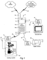
- FIG 1 is intended to illustrate the general inventive concept according to the present invention, i.e. that a user of a mobile telephone 1 or another type of portable telecommunication apparatus will be able to access, control and operate a plurality of telephone accessories, home appliances or other external electronic utility devices 30, 40, 50 through a WAP browser built into the mobile telephone.
- each electronic utility device 30, 40, 50 is connected (as indicated by reference numeral 33) to a respective WAP server module 31, 41, 51, from which the WAP browser of the mobile telephone 1 will receive encoded WML pages.
- the pages transmitted from the WAP server module 31, 41, 51 to the mobile telephone 1 represent the services, functionalities and applications, which are offered by the respective electronic utility device 30, 40, 50.
- the information contents of the WML pages may change dynamically, and moreover the user may feed back information to the respective utility device 30, 40, 50 by e.g. filling in WML forms and pushing the information back to the WAP server module 31, 41, 51 and the utility device 30, 40, 50.
- the user of the mobile telephone 1 may operate the respective utility device 30, 40, 50 and control the functionality thereof.
- the mobile telephone 1 comprises an antenna 10, which in a conventional way is used for connecting the mobile telephone 1 to a mobile telecommunications network 21 through a radio link 23.
- the mobile telecommunications network 21 for instance GSM, offers voice, data and fax call services to the user of the mobile telephone 1.
- the user of the mobile telephone 1 may also access the Internet 20, or another global information network, by using the built-in WAP browser of the mobile telephone 1.
- graphic information and/or text is presented on a display 13, and a set of cursor navigation keys 14a are provided in a keypad together with a set of ordinary mobile telephone keys 14b.
- the latter comprise e.g. a YES/OK/ANSWER key, a NO/CANCEL/HANG UP key, numeric keys 0-9 as well as other character keys, such as * and #.
- the mobile telephone 1 also comprises a loudspeaker 11 and a microphone 12.
- the mobile telephone 1 of the preferred embodiment shown in FIG 1 comprises an infrared interface 15, such as an IrDA port, by means of which the mobile telephone 1 may be connected via a first WAP server module 41 to a first electronic utility device in the form of a television set 40 in FIG 1.
- the mobile telephone 1 also comprises a system or accessories connector 16, by means of which the mobile telephone 1 may be connected, through a serial cable 52 (e.g. RS232) and a second WAP server module 51, to a second electronic utility device in the form of a digital camera 50 of FIG 1.
- a serial cable 52 e.g. RS232
- a second WAP server module 51 e.g. RS232
- the mobile telephone 1 additionally comprises a second antenna 17 for establishing a short-range radio link 32, such as a Bluetooth link, to a third electronic utility device in the form of a vending machine in FIG 1, via a third WAP server module 31.
- a short-range radio link 32 such as a Bluetooth link
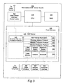
- a controller or CPU 210 is coupled to a random access memory 220 and to drivers 250 for the user interface formed by the display 13 and the keypad 14a-b.
- the controller 210 is also connected to a permanent memory 230 in the form of a flash memory.
- the flash memory 230 comprises an operating system 232 as well as an information access program in the form of a WAP client 240, which will be described in more detail below.
- the mobile telephone also comprises physical interfaces 260, 262 and 264 for the external device interfaces 15, 16 and 17 in FIG 1.
- interface 260 is an RS232 module for the system or accessories connector 16
- interface 262 is an IrDA module
- interface 264 is a Bluetooth module.
- the WAP client 240 comprises a stack of protocols 241-246 as well as a datapath selector 248, the purpose of which will be described later.
- a WAP browser application is provided, which when executed by the controller 210 will form a graphical user interface on the display 13 and allow the user to access the respective WAP server modules 31, 41, 51 of the available electronic utility devices 30, 40, 50.
- a second level 242 is a wireless session protocol.
- a wireless transport protocol and a wireless datagram protocol are provided, respectively.
- the protocols 241-244 are all essentially known per se and are not described in more detail herein.
- a respective adaption layer is provided for the serial cable interface 16, 260, the infrared interface 15, 262 and the Bluetooth interface 17, 264.
- the physical layer of the respective interface is provided as a sixth protocol level 246.
- the adaption layer 245 thus adapts the overlying wireless datagram protocol 244 to three different bearers, i.e. cable, infrared and Bluetooth.
- GSM layer 245, 246 is also provided, as is generally known in the field of mobile WAP telephones, for providing the first communication link 22 between the antenna 10 and the Internet 20(FIG 1).
- the purpose of the datapath selector 248 is to direct WML requests from the WAP browser 241 to either the first communication link 22 (through a circuit-switched GSM data call connection or through SMS-Short Messages Services), or to the respective external device interface 16, 52, 260 (cable), 15, 42, 262 (infrared) and 17, 32, 164 (Bluetooth).
- this differentiation is achieved through a new address scheme for the Uniform Resource Identifier (URI)/Uniform Resource Locator (URL).
- URI Uniform Resource Identifier
- URL Uniform Resource Locator
- FIG 3 is a schematic illustration of an essential portion 300 of any of the stand-alone WAP server modules 31, 41, 51 shown in FIG 1.
- a controller or CPU 310 is connected to a random access memory 320 and a non-volatile memory 330, which is a flash memory in the preferred embodiment.
- the flash memory comprises an embedded WAP server 340, which will be described in more detail below.
- the WAP server module 300 further comprises a utility device interface 350, which will be used for operatively coupling the WAP server module to its electronic utility device. Consequently, the vending machine 30 in FIG 1 will be physically connected to its WAP server module 31 through a serial cable 33, the utility device interface 350 of the WAP server module 31 and a corresponding physical interface in the vending machine 30. Even if a serial cable 33 is used according to the preferred embodiment, the WAP server module may be connected to its electronic utility device by another communication link than a serial cable.
- the WAP server module 300 finally comprises physical interfaces for connecting to the mobile telephone 1 in the form of a cable interface 360 (link 52 in FIG 1), an infrared interface 362 (link 42 in FIG 1) and a Bluetooth interface 364 (link 32 in FIG 1).
- the WAP server 340 comprises a stack of protocols 341-346, which correspond to the stack of protocols 241-246 in the mobile telephone 200 shown in FIG 2.
- a WAP server application protocol 341 is provided at the top level.
- a wireless session protocol 342 is provided at the top level.
- a wireless transport protocol 343 is provided at the top level.
- a wireless datagram protocol 344 is provided at the top level.
- an adaption layer 345 for different physical interfaces (cable, infrared or Bluetooth) and, finally, a physical interface layer 346.
- the protocol stack of the WAP server 340 is adapted to all possible bearers, even if only one physical bearer 360 is used (such as either cable, infrared or Bluetooth). This makes it easier to design a generic stand-alone WAP server module 300.
- the WAP server 340 further comprises an external file and function protocol 348 which is used for communicating with the electronic utility device 30, 40, 50 (illustrated in more detail in FIG 4) through the utility device interface 350 and the physical link 33.
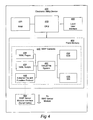
- FIG 4 is a schematic illustration of an essential portion 400 of any of the electronic utility devices shown in FIG 1, i.e. the vending machine 30, the television set 40 or the digital camera 50.
- a controller or CPU 410 is connected to a random access memory 420 and a driver 450 for a local user interface.
- the local user interface may for instance be buttons for capturing, deleting or scrolling through pictures and a miniature LCD display on the digital video camera 50, program selection buttons, volume controls, brightness controls, etc, on the television set 40, or buttons for choosing among e.g. coffee, tea, cappuccino or espresso on the vending machine 30.
- the controller 410 is coupled to a non-volatile memory 430, which is a flash memory in the preferred embodiment.
- the flash memory 430 comprises digital information (WAP contents 440), which constitute the contents that will be supplied by the WAP server module 300 to the mobile telephone 1, 200.
- the electronic utility device 400 also comprises a WAP server module interface 460 for connecting the electronic utility device 400 to the WAP server module 300 through e.g. a serial cable.
- the WAP contents 440 comprise a virtual file system 432, which has the purpose of storing a plurality of WML pages 438 and a plurality of WML scripts 439 in a structured and readable way.
- the WAP contents 440 also comprise Server Side Include (SSI) functions 436, which enable a program developer to insert directives inside the WML code to instruct the WAP server module 340 to replace the directive with a dynamic content upon retrieval of the WML code.
- SSI Server Side Include
- the WAP contents 440 also comprise Common Gateway Interface (CGI) functions 434 for enabling user input from the WAP client of the mobile telephone 1 to the WAP server module 340 and the utility device 400.
- CGI Common Gateway Interface
- the Common Gateway Interface functions 434 are a set of CGI routines that, when executed by the controller 410, controls a respective aspect or parameter of the functionality provided by the electronic utility device 400. For instance, if the utility device 400 is a digital camera 50, different CGI routines are provided for controlling e.g. the picture resolution, for scrolling through pictures stored in the camera, for capturing a new picture, for setting date/time, etc.
- the WML pages 438 and the WML scripts 439 are preferably stored as pre-compiled binary WML files. Alternatively, the contents may be stored as non-binary WML files, which are encoded into binary WML files by the WAP server 340 upon request from the WAP client 240 of the mobile telephone 1.
- the total WAP server functionality is divided into two separate parts; the stand-alone WAP server module 300 and the WAP contents 440 of the electronic utility device 400.
- all functionality data and operational parameters related to the particular electronic utility device 400 is defined by the device manufacturer and stored in the utility device itself. Therefore, the WAP server module 300 does not require any specific knowledge about the particulars of an individual electronic utility device, and thus the WAP server module 300 may be used with any electronic utility device, that fulfills the specification above.
- the manufacturer of the device 400 does not have to bother about how the actual connection is established to the portable telecommunication apparatus; this will fully be taken care of by the intermediate WAP server module 300.
- the communication between the electronic utility device 400 and the WAP server module 300 is handled by the external file and function protocol 348 and 448, which is implemented in both the WAP server module 300 and the electronic utility device 400 and allows exchange of WML pages, WML scripts as well as execution of CGI and SSI functions.
- the external file and function protocol 348, 448 contains a set of commands for performing the above, such as commands for initializing e.g.
- the external file and function protocol 348, 448 also comprises error handling.
- a dynamic menu system is implemented in the mobile telephone 1, which allows the addition of a short cut menu option for connecting to a respective utility device 30, 40, 50 through a corresponding WAP server module 31, 41, 51.
- the WAP server modules 31, 41, 51 are designed to transmit an initial sequence of identifying commands to the WAP client 240 of the mobile telephone 1/200, when the mobile telephone and the WAP server module are interconnected.
- useful information such as physical bearer type (cable, infrared or Bluetooth), possibly an address identifier (particularly in the case of Bluetooth) as well as the name of a WML start page are submitted by the WAP server 340 to the WAP client 240 upon interconnection of the mobile telephone 1/200 and the WAP server module 300.
- These parameters are stored together with the respective shortcut in the dynamic menu system of the mobile telephone 1/200.
- some of the parameters above, particularly the name of the start page may be standardized, e.g. "index.wml”.
- at least for some physical bearers, particularly Bluetooth is that the name of the start page is retrieved through service discovery.
- the digital camera 50 is capable of producing digital pictures and storing them locally in e.g. the flash memory 430.
- the digital camera 50 may be connected through a serial cable to the WAP server module 51, which in turn is connected through a serial cable 52 to the accessories interface 16 of the mobile telephone 1.
- the camera could equally well have been connected via an infrared or Bluetooth interface.
- the WAP server module 51 is provided with the WAP server 340 shown in FIG 3, and the digital camera 50 is provided with the WAP contents 440 shown in FIG 4.
- the user takes a few pictures using the digital camera 50.
- the user then connects his/her mobile telephone 1 to the WAP server module by means of the serial cable 52.
- a WML start page is then fetched by the WAP server 340 from the camera 50 and forwarded to the WAP client 240 across the serial cable 52, and the start page is presented on the display 13.
- the start page contains a plurality of controls, representing different functions of the digital camera 50.
- the user may for instance choose to view the pictures captured in the digital camera 50.
- the pictures are then sent, one by one, from the camera 50 via the WAP server 340 of the WAP server module 51/300 to the WAP client 240, which presents the pictures on the display 13 of the telephone 1.
- the user may then select one of the pictures, that he/she wants to publish on the Internet 20.
- the user may specify a certain WAP or web server available on the Internet by filling in its HTTP (Hypertext Transfer Protocol) address in a WML form submitted from the WAP server 340.
- a dial-up GSM data connection 22 (FIG 1) is established with an Internet service provider, and the WAP browser 240 of the mobile telephone 1 connects to the specified WAP or web server on the Internet.
- the selected picture is then sent over the link 22 for publication on the specified WAP or web server.
- the user disconnects the mobile telephone 1 from the WAP server module 51, wherein the logical connection between the WAP browser 240 and the WAP server 340 will be interrupted too, as well as the dial-up connection 22 to the Internet.
- the user connects his telephone to the digital camera via the WAP server module, as described above.
- the start page from the digital camera is presented on the display of the telephone.
- the user then enters a maintenance menu provided by the digital camera.
- All available settings for the digital camera are presented on a WML page submitted by the WAP server 340. These settings may for instance include the following functionality: capture picture, delete picture, scroll through pictures, resolution setting, color setting, flash mode, date/time settings, etc. The user may then select any setting and change its value.
- the changed value will be pushed back from the WAP client 240 to the WAP server 340 according to the methods described above, wherein the WAP server 340 will recognize the changed value and invoke a CGI or SSI routine in the camera 50 for changing the setting of the digital camera 50.
- the WAP server 340 will recognize the changed value and invoke a CGI or SSI routine in the camera 50 for changing the setting of the digital camera 50.
- the user is finished, he/she will disconnect the mobile telephone 1 from the WAP server module 51, as described above.
- a third use case it is assumed that the digital camera has a malfunction.
- the user notices this and connects the camera 50 to the mobile telephone 1, as described above.
- the WAP server 340 executes a predetermined error diagnosis WML page 438 stored in the camera 50, which in turns invokes a CGI routine of the CGI module 434.
- the CGI routine fetches an error code from the controller 410, and this error code is submitted together with a predetermined HTTP address by the WAP server 340 to the WAP client 240 of the mobile telephone 1.
- a dial-up GSM data connection 22 (FIG 1) is established with an Internet service provider, as described above.
- the WAP browser 240 of the mobile telephone 1 connects to the predetermined HTTP address, which points at a help-desk web site provided by the manufacturer or supplier of the digital camera 50.
- the error code is then transferred to the help-desk web site, which will return a clear-text message, illustrative image, etc., which explains the nature of the error and how it is best dealt with by the user.
- a fourth use case involves the vending machine 30 of FIG 1, which is exemplified as a machine, where a user may purchase hot drinks, such as coffee, tea, cappucino, espresso, etc.
- the user may buy a hot drink and pay for it by using his/her mobile telephone 1.
- the user connects the mobile telephone 1 to the WAP server module 31 of the vending machine 30 by e.g. invoking a short cut menu option in the mobile telephone 1.
- a WML start page will be fetched by the WAP server module 31 through the link 33 from the memory 430 of the vending machine 30, and this start page will be transmitted across the Bluetooth link 32 to the mobile telephone 1, where the WML start page will be presented by the WAP browser 240.
- the start page may for instance present a welcome message, a logotype, etc.
- the user may be presented to a form, where he/she may choose what type of hot drink to purchase.
- the price of the purchase may be presented on the display 13, together with a question whether the user wants to complete the purchase. The user accepts the purchase, and an electronic wallet in the mobile telephone may be charged.
- the server module 300 may be connected to the electronic utility device 400 in other ways than the one described above (serial cable), for instance by a wireless link, an optical link, or by direct galvanic coupling (particularly if the server module 300 is realized as an integrated circuit, which may soldered onto a printed circuit board of the electronic utility device 400).
- the WAP client of the mobile telephone may be substituted for another information access program for accessing a global information network, possibly different than Internet.
- the WAP server of the electronic utility devices may be substituted for another kind of information provider server.
Abstract
Description
- The present invention relates to the field of providing external accessibility to an electronic utility device and providing connectivity for the electronic utility device to a global information network, such as the Internet.
- More specifically, the invention is directed at the use of a portable telecommunication apparatus together with a separate server device for accessing, controlling and operating an electronic utility device.
- A portable telecommunication apparatus as set out above may for instance be a mobile or cellular radio telephone for GSM (Global System for Mobile Communication) or any other existing mobile telecommunications system. Moreover, an electronic utility device according to the above may be an advanced accessory for the mobile telephone, for instance a satellite navigation module (GPS), an FM radio or a digital video camera.
- An electronic utility device according to the above may also be e.g. a video recorder, a digital camera, a television set, a hifi stereo, or an air conditioner.
- The various examples of electronic utility devices given above all have in common that they may normally be operated by a remote control unit, such as an infrared remote control unit, in addition to a local user interface provided at a control panel of the device itself, such as a set of control buttons and LED indicators. Typically, a separate remote control unit is used for each individual electronic utility device.
- Although some infrared remote control units are programmable and may therefore be adapted for use with several electronic utility devices, the existing approach has several drawbacks. First of all, remote control units have a tendency of disappearing in many homes, especially in families where small children are present. Furthermore, the various remote control units will have to be kept within reach of the intended user and will therefore occupy unnecessary storage space on desktops, table surfaces, etc. Moreover, the user interface of a typical remote control unit has a low level of user friendliness; the user interface is restricted to various small keys or buttons, at best in conjunction with a miniature LCD display. Finally, each type of remote control unit has its own philosophy behind the layout of the keys, etc, thereby making it hard for users to get familiar with all different types of remote control units.
- Even if infrared remote control units are available for certain electronic utility devices, they have no capabilities of providing connectivity for the electronic utility device to a global information network, such as the Internet. Connectivity to e.g. the Internet is desired e.g. for distributing information (such as pictures captured by a digital camera) or for performing error reporting and trouble shooting together with a web-based helpdesk run by a manufacturer or supplier of the electronic utility device in question.
- Other electronic utility devices, such as printers, telefax machines, copying machines, or home appliances such as refrigerators or microwave ovens, are usually not operated from an infrared control unit. Instead, the user of these devices is restricted to a normally very limited local user interface, such as a few control buttons and LED indicators, provided at a control panel of the device.
- DE 4 321 304 A1 discloses a system for controlling and/or monitoring communication and function devices in the private and commercial field by means of a remote control unit.
- Consequently, there is a need for a well-defined, simple and inexpensive way for a manufacturer of electronic utility devices to provide remote accessibility to the device. Correspondingly, there is a need for a well-defined, simple and inexpensive way for the utility device manufacturer to provide connectivity for the utility device to a global information network, such as the Internet.
- It is an object of the present invention to provide an easier way of accessing, controlling and operating electronic utility devices in a standardized and user-friendly fashion. A second object of the invention is to drastically reduce the number of required remote control units, specifically so that only one control apparatus is required for a large number of electronic utility devices, which may exist in the environment around a user. A third object is to provide an opportunity of remote control of electronic utility devices that traditionally are not provided with such an option. A fourth object is to provide an option for various types of electronic utility devices to connect to a global information network, such as the Internet, by using a single type of communication device, namely a portable telecommunication apparatus.
- The above objects have been achieved by the inventive understanding that remote accessibility as well as connectivity to e.g. the Internet may be provided for an electronic utility device through a portable telecommunication apparatus by the use of an intermediate stand-alone server device, which communicates with a client program in the portable telecommunication apparatus.
- According to a preferred embodiment of the invention, a mobile WAP (Wireless Application Protocol) telephone having a built-in WAP browser is designed to connect via a point-to-point communication link to a stand-alone WAP server module or device through an accessories interface, such as a short-range radio link, an infrared link or a serial cable link. The WAP server module is provided with an embedded WAP server and an interface for connecting to an electronic utility device. The electronic utility device stores information related to the device functionality in the form of WML (Wireless Markup Language) pages and WML scripts. This information may be transferred to the WAP server of the WAP server module, which in turn may forward the information to the WAP client of the portable telecommunication apparatus to be presented to a user. Control information may be entered by the user through the WAP client and transferred to the WAP server and, ultimately, the electronic utility device, so that the functionality thereof may be remotely controlled from the portable telecommunication apparatus.
- A solution to the above objects is defined by the appended independent patent claims. Other features, advantages and objects of the invention will appear from the following detailed disclosure of a preferred embodiment, from the appended drawings as well as from the subclaims.
- The present invention will now be described in more detail with reference to the appended drawings, in which
- FIG 1 is a schematic illustration of a mobile WAP telephone, which may be used for accessing the Internet, for performing traditional mobile telecommunications service calls (voice, data and fax), and for accessing, controlling and operating a plurality of electronic utility devices through stand-alone WAP server modules,
- FIG 2 is a schematic block diagram of the mobile telephone of FIG 1,
- FIG 3 is a schematic block diagram of a stand-alone WAP server module according to a preferred embodiment of the invention, and
- FIG 4 is a schematic block diagram of one of the external utility devices of FIG 1.
-
- FIG 1 is intended to illustrate the general inventive concept according to the present invention, i.e. that a user of a
mobile telephone 1 or another type of portable telecommunication apparatus will be able to access, control and operate a plurality of telephone accessories, home appliances or other externalelectronic utility devices electronic utility device WAP server module mobile telephone 1 will receive encoded WML pages. The pages transmitted from theWAP server module mobile telephone 1 represent the services, functionalities and applications, which are offered by the respectiveelectronic utility device respective utility device WAP server module utility device mobile telephone 1 may operate therespective utility device - As shown in FIG 1, the
mobile telephone 1 comprises anantenna 10, which in a conventional way is used for connecting themobile telephone 1 to amobile telecommunications network 21 through aradio link 23. In a well-known way, themobile telecommunications network 21, for instance GSM, offers voice, data and fax call services to the user of themobile telephone 1. By means of theantenna 10, the user of themobile telephone 1 may also access the Internet 20, or another global information network, by using the built-in WAP browser of themobile telephone 1. To this end, graphic information and/or text is presented on adisplay 13, and a set ofcursor navigation keys 14a are provided in a keypad together with a set of ordinarymobile telephone keys 14b. The latter comprise e.g. a YES/OK/ANSWER key, a NO/CANCEL/HANG UP key, numeric keys 0-9 as well as other character keys, such as * and #. - As is well known, the
mobile telephone 1 also comprises aloudspeaker 11 and amicrophone 12. Moreover, themobile telephone 1 of the preferred embodiment shown in FIG 1 comprises aninfrared interface 15, such as an IrDA port, by means of which themobile telephone 1 may be connected via a firstWAP server module 41 to a first electronic utility device in the form of atelevision set 40 in FIG 1. - The
mobile telephone 1 also comprises a system oraccessories connector 16, by means of which themobile telephone 1 may be connected, through a serial cable 52 (e.g. RS232) and a secondWAP server module 51, to a second electronic utility device in the form of adigital camera 50 of FIG 1. - The
mobile telephone 1 additionally comprises asecond antenna 17 for establishing a short-range radio link 32, such as a Bluetooth link, to a third electronic utility device in the form of a vending machine in FIG 1, via a thirdWAP server module 31. - An
essential portion 200 of themobile telephone 1 is shown in FIG 2. A controller orCPU 210 is coupled to arandom access memory 220 and todrivers 250 for the user interface formed by thedisplay 13 and thekeypad 14a-b. Thecontroller 210 is also connected to apermanent memory 230 in the form of a flash memory. Theflash memory 230 comprises anoperating system 232 as well as an information access program in the form of aWAP client 240, which will be described in more detail below. The mobile telephone also comprisesphysical interfaces external device interfaces interface 260 is an RS232 module for the system oraccessories connector 16,interface 262 is an IrDA module, andinterface 264 is a Bluetooth module. - As shown in FIG 2, the
WAP client 240 comprises a stack of protocols 241-246 as well as adatapath selector 248, the purpose of which will be described later. On a first level or top level 241 a WAP browser application is provided, which when executed by thecontroller 210 will form a graphical user interface on thedisplay 13 and allow the user to access the respectiveWAP server modules electronic utility devices second level 242 is a wireless session protocol. As a third and fourth level, respectively, a wireless transport protocol and a wireless datagram protocol are provided, respectively. The protocols 241-244 are all essentially known per se and are not described in more detail herein. - On a fifth level 245 a respective adaption layer is provided for the
serial cable interface infrared interface Bluetooth interface sixth protocol level 246. Theadaption layer 245 thus adapts the overlyingwireless datagram protocol 244 to three different bearers, i.e. cable, infrared and Bluetooth. - Moreover, a
GSM layer first communication link 22 between theantenna 10 and the Internet 20(FIG 1). - The purpose of the
datapath selector 248 is to direct WML requests from theWAP browser 241 to either the first communication link 22 (through a circuit-switched GSM data call connection or through SMS-Short Messages Services), or to the respectiveexternal device interface first communication link 22 to ordinary web sites on theInternet 20, the ordinary URI/URL format "http://..." may be used. Conversely, when any of theelectronic utility devices - FIG 3 is a schematic illustration of an
essential portion 300 of any of the stand-aloneWAP server modules CPU 310 is connected to arandom access memory 320 and anon-volatile memory 330, which is a flash memory in the preferred embodiment. The flash memory comprises an embeddedWAP server 340, which will be described in more detail below. - The
WAP server module 300 further comprises autility device interface 350, which will be used for operatively coupling the WAP server module to its electronic utility device. Consequently, thevending machine 30 in FIG 1 will be physically connected to itsWAP server module 31 through aserial cable 33, theutility device interface 350 of theWAP server module 31 and a corresponding physical interface in thevending machine 30. Even if aserial cable 33 is used according to the preferred embodiment, the WAP server module may be connected to its electronic utility device by another communication link than a serial cable. - Referring back to FIG 3, the
WAP server module 300 finally comprises physical interfaces for connecting to themobile telephone 1 in the form of a cable interface 360 (link 52 in FIG 1), an infrared interface 362 (link 42 in FIG 1) and a Bluetooth interface 364 (link 32 in FIG 1). - The
WAP server 340 comprises a stack of protocols 341-346, which correspond to the stack of protocols 241-246 in themobile telephone 200 shown in FIG 2. At the top level a WAPserver application protocol 341 is provided. Then follows awireless session protocol 342, a wireless transport protocol 343, awireless datagram protocol 344, anadaption layer 345 for different physical interfaces (cable, infrared or Bluetooth) and, finally, aphysical interface layer 346. Preferably, the protocol stack of theWAP server 340 is adapted to all possible bearers, even if only onephysical bearer 360 is used (such as either cable, infrared or Bluetooth). This makes it easier to design a generic stand-aloneWAP server module 300. - The
WAP server 340 further comprises an external file andfunction protocol 348 which is used for communicating with theelectronic utility device utility device interface 350 and thephysical link 33. - FIG 4 is a schematic illustration of an
essential portion 400 of any of the electronic utility devices shown in FIG 1, i.e. thevending machine 30, thetelevision set 40 or thedigital camera 50. A controller orCPU 410 is connected to arandom access memory 420 and adriver 450 for a local user interface. The local user interface may for instance be buttons for capturing, deleting or scrolling through pictures and a miniature LCD display on thedigital video camera 50, program selection buttons, volume controls, brightness controls, etc, on thetelevision set 40, or buttons for choosing among e.g. coffee, tea, cappuccino or espresso on thevending machine 30. - The
controller 410 is coupled to anon-volatile memory 430, which is a flash memory in the preferred embodiment. Theflash memory 430 comprises digital information (WAP contents 440), which constitute the contents that will be supplied by theWAP server module 300 to themobile telephone - The
electronic utility device 400 also comprises a WAPserver module interface 460 for connecting theelectronic utility device 400 to theWAP server module 300 through e.g. a serial cable. - The
WAP contents 440 comprise avirtual file system 432, which has the purpose of storing a plurality ofWML pages 438 and a plurality ofWML scripts 439 in a structured and readable way. TheWAP contents 440 also comprise Server Side Include (SSI) functions 436, which enable a program developer to insert directives inside the WML code to instruct theWAP server module 340 to replace the directive with a dynamic content upon retrieval of the WML code. - The
WAP contents 440 also comprise Common Gateway Interface (CGI) functions 434 for enabling user input from the WAP client of themobile telephone 1 to theWAP server module 340 and theutility device 400. The Common Gateway Interface functions 434 are a set of CGI routines that, when executed by thecontroller 410, controls a respective aspect or parameter of the functionality provided by theelectronic utility device 400. For instance, if theutility device 400 is adigital camera 50, different CGI routines are provided for controlling e.g. the picture resolution, for scrolling through pictures stored in the camera, for capturing a new picture, for setting date/time, etc. - The WML pages 438 and the
WML scripts 439 are preferably stored as pre-compiled binary WML files. Alternatively, the contents may be stored as non-binary WML files, which are encoded into binary WML files by theWAP server 340 upon request from theWAP client 240 of themobile telephone 1. - As appears from the above, the total WAP server functionality is divided into two separate parts; the stand-alone
WAP server module 300 and theWAP contents 440 of theelectronic utility device 400. This has several advantages. Firstly, all functionality data and operational parameters related to the particular electronic utility device 400 (digital camera, vending machine, etc) is defined by the device manufacturer and stored in the utility device itself. Therefore, theWAP server module 300 does not require any specific knowledge about the particulars of an individual electronic utility device, and thus theWAP server module 300 may be used with any electronic utility device, that fulfills the specification above. Moreover, the manufacturer of thedevice 400 does not have to bother about how the actual connection is established to the portable telecommunication apparatus; this will fully be taken care of by the intermediateWAP server module 300. - The communication between the
electronic utility device 400 and theWAP server module 300 is handled by the external file andfunction protocol WAP server module 300 and theelectronic utility device 400 and allows exchange of WML pages, WML scripts as well as execution of CGI and SSI functions. The external file andfunction protocol memory 430 of theelectronic utility device 400; commands for opening and closing such a file; commands for reading from and writing to such a file; and commands for invoking CGI and SSI functions in thememory 430 of theelectronic utility device 400. The external file andfunction protocol - The rest of this specification will deal with the use of the
mobile telephone 1/200 of FIG 2 for controlling theelectronic utility device 440 of FIG 4 through theWAP server module 300 of FIG 3. Obviously, the user must be able to easily access at least his/her favoriteelectronic utility devices mobile telephone 1. Preferably, a dynamic menu system is implemented in themobile telephone 1, which allows the addition of a short cut menu option for connecting to arespective utility device WAP server module WAP server modules WAP client 240 of themobile telephone 1/200, when the mobile telephone and the WAP server module are interconnected. - Thus, useful information such as physical bearer type (cable, infrared or Bluetooth), possibly an address identifier (particularly in the case of Bluetooth) as well as the name of a WML start page are submitted by the
WAP server 340 to theWAP client 240 upon interconnection of themobile telephone 1/200 and theWAP server module 300. These parameters are stored together with the respective shortcut in the dynamic menu system of themobile telephone 1/200. Alternatively, some of the parameters above, particularly the name of the start page, may be standardized, e.g. "index.wml". Still another alternative, at least for some physical bearers, particularly Bluetooth, is that the name of the start page is retrieved through service discovery. - Three use cases involving the
mobile telephone 1 and thedigital camera 50 will now be described. It is assumed that thedigital camera 50 is capable of producing digital pictures and storing them locally in e.g. theflash memory 430. As described above, thedigital camera 50 may be connected through a serial cable to theWAP server module 51, which in turn is connected through aserial cable 52 to theaccessories interface 16 of themobile telephone 1. Obviously, the camera could equally well have been connected via an infrared or Bluetooth interface. TheWAP server module 51 is provided with theWAP server 340 shown in FIG 3, and thedigital camera 50 is provided with theWAP contents 440 shown in FIG 4. - Initially, the user takes a few pictures using the
digital camera 50. The user then connects his/hermobile telephone 1 to the WAP server module by means of theserial cable 52. A WML start page is then fetched by theWAP server 340 from thecamera 50 and forwarded to theWAP client 240 across theserial cable 52, and the start page is presented on thedisplay 13. The start page contains a plurality of controls, representing different functions of thedigital camera 50. The user may for instance choose to view the pictures captured in thedigital camera 50. The pictures are then sent, one by one, from thecamera 50 via theWAP server 340 of theWAP server module 51/300 to theWAP client 240, which presents the pictures on thedisplay 13 of thetelephone 1. - The user may then select one of the pictures, that he/she wants to publish on the
Internet 20. The user may specify a certain WAP or web server available on the Internet by filling in its HTTP (Hypertext Transfer Protocol) address in a WML form submitted from theWAP server 340. A dial-up GSM data connection 22 (FIG 1) is established with an Internet service provider, and theWAP browser 240 of themobile telephone 1 connects to the specified WAP or web server on the Internet. The selected picture is then sent over thelink 22 for publication on the specified WAP or web server. Finally, the user disconnects themobile telephone 1 from theWAP server module 51, wherein the logical connection between theWAP browser 240 and theWAP server 340 will be interrupted too, as well as the dial-upconnection 22 to the Internet. - In the second use case, the user connects his telephone to the digital camera via the WAP server module, as described above. The start page from the digital camera is presented on the display of the telephone. The user then enters a maintenance menu provided by the digital camera. All available settings for the digital camera are presented on a WML page submitted by the
WAP server 340. These settings may for instance include the following functionality: capture picture, delete picture, scroll through pictures, resolution setting, color setting, flash mode, date/time settings, etc. The user may then select any setting and change its value. The changed value will be pushed back from theWAP client 240 to theWAP server 340 according to the methods described above, wherein theWAP server 340 will recognize the changed value and invoke a CGI or SSI routine in thecamera 50 for changing the setting of thedigital camera 50. When the user is finished, he/she will disconnect themobile telephone 1 from theWAP server module 51, as described above. - In a third use case it is assumed that the digital camera has a malfunction. The user notices this and connects the
camera 50 to themobile telephone 1, as described above. TheWAP server 340 executes a predetermined errordiagnosis WML page 438 stored in thecamera 50, which in turns invokes a CGI routine of theCGI module 434. The CGI routine fetches an error code from thecontroller 410, and this error code is submitted together with a predetermined HTTP address by theWAP server 340 to theWAP client 240 of themobile telephone 1. A dial-up GSM data connection 22 (FIG 1) is established with an Internet service provider, as described above. TheWAP browser 240 of themobile telephone 1 connects to the predetermined HTTP address, which points at a help-desk web site provided by the manufacturer or supplier of thedigital camera 50. The error code is then transferred to the help-desk web site, which will return a clear-text message, illustrative image, etc., which explains the nature of the error and how it is best dealt with by the user. - A fourth use case involves the
vending machine 30 of FIG 1, which is exemplified as a machine, where a user may purchase hot drinks, such as coffee, tea, cappucino, espresso, etc. The user may buy a hot drink and pay for it by using his/hermobile telephone 1. As described above, the user connects themobile telephone 1 to theWAP server module 31 of thevending machine 30 by e.g. invoking a short cut menu option in themobile telephone 1. A WML start page will be fetched by theWAP server module 31 through thelink 33 from thememory 430 of thevending machine 30, and this start page will be transmitted across the Bluetooth link 32 to themobile telephone 1, where the WML start page will be presented by theWAP browser 240. The start page may for instance present a welcome message, a logotype, etc. - In a subsequent WML page, the user may be presented to a form, where he/she may choose what type of hot drink to purchase. In a third WML page, the price of the purchase may be presented on the
display 13, together with a question whether the user wants to complete the purchase. The user accepts the purchase, and an electronic wallet in the mobile telephone may be charged. - The present invention has been described above with reference to a preferred embodiment. However, other embodiments than the one described above are equally possible within the scope of the invention, as defined by the appended independent claims, which is readily realized by a man skilled in the art. Specifically, other physical bearers than cable, infrared and short-range radio link are possible within the scope of the invention. Also, the invention is applicable to other electronic utility devices than the ones exemplified above, including but not limited to video recorders, hifi stereos, air conditioners, refrigerators or microwave ovens.
- The
server module 300 may be connected to theelectronic utility device 400 in other ways than the one described above (serial cable), for instance by a wireless link, an optical link, or by direct galvanic coupling (particularly if theserver module 300 is realized as an integrated circuit, which may soldered onto a printed circuit board of the electronic utility device 400). - Moreover, the WAP client of the mobile telephone may be substituted for another information access program for accessing a global information network, possibly different than Internet. Correspondingly, the WAP server of the electronic utility devices may be substituted for another kind of information provider server.
Claims (13)
- A server device (31, 41, 51, 300) comprising a programmable controller (310), a memory (320, 330) coupled to the controller, and a server program (340) stored in the memory and executable by the controller, characterized by
at least a first interface (360-364) adapted to establish a first communication link (32, 42, 52) to a portable telecommunication apparatus (1, 200),
at least a second interface (350) for connecting the server device to an electronic utility device (30, 40, 50, 400),
wherein the server program (340) is adapted to communicate with a client program (240) in the portable telecommunication apparatus, according to at least one protocol (341-346) for accessing a global information network (20), through the first interface, and is adapted to communicate with the electronic utility device through the second interface, so that digital information may be transferred between the portable telecommunication apparatus and the electronic utility device. - A server device as in claim 1, wherein the server program (340) is adapted to receive digital control information related to a functionality of the electronic utility device (30, 40, 50, 400) from the portable telecommunication apparatus (1, 200) and forward this control information to the electronic utility device.
- A server device as in claim 1 or 2, wherein the server program (340) is adapted to retrieve digital information related to an operational status of the electronic utility device (30, 40, 50, 400) and forward this information to the portable telecommunication apparatus (1, 200).
- A server device as in claim 3, wherein the at least one protocol (341-346) is a protocol for accessing the Internet (20).
- A server device as in any preceding claim, wherein the server program (340) comprises a WAP server (341).
- A server device as in claim 5, wherein the server program (340) is adapted to receive WML pages and/or WML scripts from the electronic utility device (30, 40, 50, 400).
- A server device as in any preceding claim, wherein the first communication link (32, 42, 52) is a short-range radio link (32), an infrared link (42) or a serial cable link (52).
- A server device as in any preceding claim, wherein the second interface (350) is a serial cable interface.
- A method of operating an electronic utility device (400) from a portable telecommunication apparatus (1, 200) having a client program (240) for accessing a global information network (20), characterized by the steps of:providing a server device (300) having a server program (340);providing a communication link (32, 42, 52), capable of transferring digital information in accordance with at least one protocol (341-346) for accessing the global information network (20), between the server device and the portable telecommunication apparatus;connecting the electronic utility device (400) to the server device; andtransmitting digital information (438-439), which is related to a functionality of the electronic utility device, between the electronic utility device and the server program (340) of the server device, and between the server program (340) of the server device and the client program (240) of the portable telecommunication apparatus.
- A method as in claim 9, wherein the server program (340) of the server device (300) is a WAP server and the client program (240) of the portable telecommunication apparatus (1, 200) is a WAP client.
- A method as in claim 9 or 10, comprising the further steps of:connecting to the global information network (20) from the client program (240) of the portable telecommunication apparatus (1, 200); andcommunicating digital information between the electronic utility device (400) and the global information network via the server program (340) of the server device (300) and the client program (240) of the portable telecommunication apparatus (1, 200).
- A method as in any of claims 9-11, comprising the further step of storing at least a part of the digital information as WML pages (438) and/or WML scripts (439) in a memory (430, 400) of the electronic utility device (400).
- A method as in any of claims 9-12, wherein the portable telecommunication apparatus (1, 200) is a mobile telephone.
Applications Claiming Priority (3)
| Application Number | Priority Date | Filing Date | Title |
|---|---|---|---|
| SE9904373 | 1999-12-01 | ||
| SE9904373A SE521557C2 (en) | 1999-12-01 | 1999-12-01 | Device and method for operating an electronic consumer product from a portable telecommunications device |
| PCT/SE2000/002399 WO2001041408A1 (en) | 1999-12-01 | 2000-12-01 | A device and a method for operating an electronic utility device from a portable telecommunication apparatus |
Publications (2)
| Publication Number | Publication Date |
|---|---|
| EP1234436A1 EP1234436A1 (en) | 2002-08-28 |
| EP1234436B1 true EP1234436B1 (en) | 2005-08-03 |
Family
ID=20417943
Family Applications (1)
| Application Number | Title | Priority Date | Filing Date |
|---|---|---|---|
| EP00982040A Expired - Lifetime EP1234436B1 (en) | 1999-12-01 | 2000-12-01 | A device and a method for operating an electronic utility device from a portable telecommunication apparatus |
Country Status (8)
| Country | Link |
|---|---|
| EP (1) | EP1234436B1 (en) |
| JP (1) | JP2003516044A (en) |
| CN (1) | CN1227886C (en) |
| AT (1) | ATE301366T1 (en) |
| AU (1) | AU1911601A (en) |
| DE (1) | DE60021755T2 (en) |
| SE (1) | SE521557C2 (en) |
| WO (1) | WO2001041408A1 (en) |
Families Citing this family (11)
| Publication number | Priority date | Publication date | Assignee | Title |
|---|---|---|---|---|
| US8903737B2 (en) * | 2000-04-25 | 2014-12-02 | Accenture Global Service Limited | Method and system for a wireless universal mobile product interface |
| GB0011876D0 (en) * | 2000-05-18 | 2000-07-05 | Ascot Management Solutions Ltd | Displaying of WAP phone information |
| DE10044528A1 (en) * | 2000-09-04 | 2002-03-14 | Mannesmann Ag | Method for remote monitoring of sensors and actuators in house installations using a mobile radio terminal |
| CN1209895C (en) * | 2001-08-14 | 2005-07-06 | 索尼公司 | Information processing device and information processing method |
| US20030055909A1 (en) * | 2001-08-24 | 2003-03-20 | Stephan Hartwig | Pluggable server module for wireless remote controlling of devices |
| ATE301859T1 (en) * | 2002-03-05 | 2005-08-15 | Scheidt & Bachmann Gmbh | METHOD FOR OPERATING ATMS IN THE CASHLESS PROCESSING OF ATM USAGE PROCESSES |
| DE60319387D1 (en) * | 2003-11-10 | 2008-04-10 | Ericsson Telefon Ab L M | A method and system for communicating between a client and a server, wherein the client selects one of multiple physical connections |
| GB2410868A (en) * | 2004-02-07 | 2005-08-10 | Boris Tsukerman | Integration of 3G telephone with television set for making video calls |
| FR2871324B1 (en) * | 2004-06-08 | 2006-12-01 | Luc Jarry | DEVICE FOR PROCESSING INFORMATION FROM SENSORS AND / OR INTENDED FOR ACTUATORS INVOLVING A MOBILE RADIOTELEPHONE |
| KR100664162B1 (en) | 2004-10-14 | 2007-01-04 | 엘지전자 주식회사 | Mobile terminal and method for realizing function using pld thereof |
| JP4974465B2 (en) * | 2005-02-07 | 2012-07-11 | 日本電信電話株式会社 | Wireless terminal device |
Family Cites Families (5)
| Publication number | Priority date | Publication date | Assignee | Title |
|---|---|---|---|---|
| DE4321304A1 (en) * | 1993-06-26 | 1995-03-02 | Domarkas Brigitte | System for controlling and/or monitoring devices |
| DE4421307A1 (en) * | 1994-06-17 | 1995-12-21 | Siemens Ag | Remote control arrangement for electrical devices |
| US6223029B1 (en) * | 1996-03-14 | 2001-04-24 | Telefonaktiebolaget Lm Ericsson (Publ) | Combined mobile telephone and remote control terminal |
| JP3911047B2 (en) * | 1996-04-30 | 2007-05-09 | ソニー株式会社 | Recording reservation control system and recording reservation control method |
| JPH1097966A (en) * | 1996-07-31 | 1998-04-14 | Canon Inc | Remote controlled maintenance system for industrial equipment and production method utilizing the same |
-
1999
- 1999-12-01 SE SE9904373A patent/SE521557C2/en not_active IP Right Cessation
-
2000
- 2000-12-01 JP JP2001541220A patent/JP2003516044A/en active Pending
- 2000-12-01 DE DE60021755T patent/DE60021755T2/en not_active Expired - Lifetime
- 2000-12-01 CN CNB008166692A patent/CN1227886C/en not_active Expired - Lifetime
- 2000-12-01 EP EP00982040A patent/EP1234436B1/en not_active Expired - Lifetime
- 2000-12-01 AT AT00982040T patent/ATE301366T1/en not_active IP Right Cessation
- 2000-12-01 AU AU19116/01A patent/AU1911601A/en not_active Abandoned
- 2000-12-01 WO PCT/SE2000/002399 patent/WO2001041408A1/en active IP Right Grant
Also Published As
| Publication number | Publication date |
|---|---|
| ATE301366T1 (en) | 2005-08-15 |
| CN1227886C (en) | 2005-11-16 |
| WO2001041408A1 (en) | 2001-06-07 |
| SE9904373D0 (en) | 1999-12-01 |
| EP1234436A1 (en) | 2002-08-28 |
| SE9904373L (en) | 2001-06-02 |
| CN1408171A (en) | 2003-04-02 |
| DE60021755D1 (en) | 2005-09-08 |
| AU1911601A (en) | 2001-06-12 |
| DE60021755T2 (en) | 2006-04-13 |
| JP2003516044A (en) | 2003-05-07 |
| SE521557C2 (en) | 2003-11-11 |
Similar Documents
| Publication | Publication Date | Title |
|---|---|---|
| US6968365B2 (en) | Device and a method for operating an electronic utility device from a portable telecommunication apparatus | |
| US6763247B1 (en) | Portable telecommunication apparatus for controlling an electronic utility device | |
| US6133847A (en) | Configurable remote control device | |
| US6922258B2 (en) | Method and apparatus for printing remote images using a mobile device and printer | |
| EP1456743B1 (en) | Method and apparatus for providing output from remotely located digital files using a mobile and output device | |
| EP2707804B1 (en) | Portable terminal and method for transferring data of a peripheral device via the portable terminal | |
| KR100437849B1 (en) | Network connection apparatus and network system using this | |
| JP2004005636A (en) | System and method for personalizing user interface of electronic appliance | |
| US20030005330A1 (en) | Portable wireless device and software for printing by reference | |
| EP1234436B1 (en) | A device and a method for operating an electronic utility device from a portable telecommunication apparatus | |
| EP1234465B1 (en) | A portable telecommunication apparatus for controlling an electronic utility device | |
| US20090213228A1 (en) | Method For Specifying Image Handling For Images On A Portable Device | |
| KR20010108113A (en) | Telephone handset for use in interactive tv systems | |
| US7385718B2 (en) | Print by reference method for portable wireless devices | |
| US20030022677A1 (en) | Transporting data | |
| JP4114127B2 (en) | COMMUNICATION DEVICE, COMMUNICATION METHOD, COMPUTER-READABLE RECORDING MEDIUM CONTAINING COMMUNICATION PROGRAM, AND SERVICE SYSTEM | |
| US20020019854A1 (en) | Method of accessing remote data | |
| KR101454044B1 (en) | Method and apparatus for customizing syndicated data feeds | |
| KR100539889B1 (en) | How to display pictures on your phone | |
| JP4840264B2 (en) | Television system | |
| KR20010109763A (en) | Method and system for providing image data using mobile phone | |
| KR20020004642A (en) | System for providing communication between subscribers on internet | |
| JP2007086999A (en) | Attribute management device, image forming device, data print system and data print method | |
| JP2008158807A (en) | Radio communication device, information processor, program, and method of utilizing received information |
Legal Events
| Date | Code | Title | Description |
|---|---|---|---|
| PUAI | Public reference made under article 153(3) epc to a published international application that has entered the european phase |
Free format text: ORIGINAL CODE: 0009012 |
|
| 17P | Request for examination filed |
Effective date: 20020427 |
|
| AK | Designated contracting states |
Kind code of ref document: A1 Designated state(s): AT BE CH CY DE DK ES FI FR GB GR IE IT LI LU MC NL PT SE TR |
|
| AX | Request for extension of the european patent |
Free format text: AL;LT;LV;MK;RO;SI |
|
| RIN1 | Information on inventor provided before grant (corrected) |
Inventor name: OLSSON, PATRIK Inventor name: TILLGREN, MAGNUS Inventor name: HOLLSTROEM, MAGNUS Inventor name: HED, ROBERT |
|
| RAP1 | Party data changed (applicant data changed or rights of an application transferred) |
Owner name: TELEFONAKTIEBOLAGET LM ERICSSON (PUBL) |
|
| GRAP | Despatch of communication of intention to grant a patent |
Free format text: ORIGINAL CODE: EPIDOSNIGR1 |
|
| GRAS | Grant fee paid |
Free format text: ORIGINAL CODE: EPIDOSNIGR3 |
|
| GRAA | (expected) grant |
Free format text: ORIGINAL CODE: 0009210 |
|
| AK | Designated contracting states |
Kind code of ref document: B1 Designated state(s): AT BE CH CY DE DK ES FI FR GB GR IE IT LI LU MC NL PT SE TR |
|
| PG25 | Lapsed in a contracting state [announced via postgrant information from national office to epo] |
Ref country code: IT Free format text: LAPSE BECAUSE OF FAILURE TO SUBMIT A TRANSLATION OF THE DESCRIPTION OR TO PAY THE FEE WITHIN THE PRESCRIBED TIME-LIMIT;WARNING: LAPSES OF ITALIAN PATENTS WITH EFFECTIVE DATE BEFORE 2007 MAY HAVE OCCURRED AT ANY TIME BEFORE 2007. THE CORRECT EFFECTIVE DATE MAY BE DIFFERENT FROM THE ONE RECORDED. Effective date: 20050803 Ref country code: BE Free format text: LAPSE BECAUSE OF FAILURE TO SUBMIT A TRANSLATION OF THE DESCRIPTION OR TO PAY THE FEE WITHIN THE PRESCRIBED TIME-LIMIT Effective date: 20050803 Ref country code: LI Free format text: LAPSE BECAUSE OF FAILURE TO SUBMIT A TRANSLATION OF THE DESCRIPTION OR TO PAY THE FEE WITHIN THE PRESCRIBED TIME-LIMIT Effective date: 20050803 Ref country code: CH Free format text: LAPSE BECAUSE OF FAILURE TO SUBMIT A TRANSLATION OF THE DESCRIPTION OR TO PAY THE FEE WITHIN THE PRESCRIBED TIME-LIMIT Effective date: 20050803 Ref country code: ES Free format text: LAPSE BECAUSE OF FAILURE TO SUBMIT A TRANSLATION OF THE DESCRIPTION OR TO PAY THE FEE WITHIN THE PRESCRIBED TIME-LIMIT Effective date: 20050803 Ref country code: FI Free format text: LAPSE BECAUSE OF FAILURE TO SUBMIT A TRANSLATION OF THE DESCRIPTION OR TO PAY THE FEE WITHIN THE PRESCRIBED TIME-LIMIT Effective date: 20050803 Ref country code: NL Free format text: LAPSE BECAUSE OF FAILURE TO SUBMIT A TRANSLATION OF THE DESCRIPTION OR TO PAY THE FEE WITHIN THE PRESCRIBED TIME-LIMIT Effective date: 20050803 Ref country code: TR Free format text: LAPSE BECAUSE OF FAILURE TO SUBMIT A TRANSLATION OF THE DESCRIPTION OR TO PAY THE FEE WITHIN THE PRESCRIBED TIME-LIMIT Effective date: 20050803 Ref country code: AT Free format text: LAPSE BECAUSE OF FAILURE TO SUBMIT A TRANSLATION OF THE DESCRIPTION OR TO PAY THE FEE WITHIN THE PRESCRIBED TIME-LIMIT Effective date: 20050803 |
|
| REG | Reference to a national code |
Ref country code: GB Ref legal event code: FG4D |
|
| REG | Reference to a national code |
Ref country code: CH Ref legal event code: EP |
|
| REG | Reference to a national code |
Ref country code: IE Ref legal event code: FG4D |
|
| REF | Corresponds to: |
Ref document number: 60021755 Country of ref document: DE Date of ref document: 20050908 Kind code of ref document: P |
|
| PG25 | Lapsed in a contracting state [announced via postgrant information from national office to epo] |
Ref country code: GR Free format text: LAPSE BECAUSE OF FAILURE TO SUBMIT A TRANSLATION OF THE DESCRIPTION OR TO PAY THE FEE WITHIN THE PRESCRIBED TIME-LIMIT Effective date: 20051103 Ref country code: SE Free format text: LAPSE BECAUSE OF FAILURE TO SUBMIT A TRANSLATION OF THE DESCRIPTION OR TO PAY THE FEE WITHIN THE PRESCRIBED TIME-LIMIT Effective date: 20051103 Ref country code: DK Free format text: LAPSE BECAUSE OF FAILURE TO SUBMIT A TRANSLATION OF THE DESCRIPTION OR TO PAY THE FEE WITHIN THE PRESCRIBED TIME-LIMIT Effective date: 20051103 |
|
| PG25 | Lapsed in a contracting state [announced via postgrant information from national office to epo] |
Ref country code: CY Free format text: LAPSE BECAUSE OF FAILURE TO SUBMIT A TRANSLATION OF THE DESCRIPTION OR TO PAY THE FEE WITHIN THE PRESCRIBED TIME-LIMIT Effective date: 20051201 Ref country code: IE Free format text: LAPSE BECAUSE OF NON-PAYMENT OF DUE FEES Effective date: 20051201 |
|
| PG25 | Lapsed in a contracting state [announced via postgrant information from national office to epo] |
Ref country code: MC Free format text: LAPSE BECAUSE OF NON-PAYMENT OF DUE FEES Effective date: 20051231 Ref country code: LU Free format text: LAPSE BECAUSE OF NON-PAYMENT OF DUE FEES Effective date: 20051231 |
|
| PG25 | Lapsed in a contracting state [announced via postgrant information from national office to epo] |
Ref country code: PT Free format text: LAPSE BECAUSE OF FAILURE TO SUBMIT A TRANSLATION OF THE DESCRIPTION OR TO PAY THE FEE WITHIN THE PRESCRIBED TIME-LIMIT Effective date: 20060103 |
|
| NLV1 | Nl: lapsed or annulled due to failure to fulfill the requirements of art. 29p and 29m of the patents act | ||
| REG | Reference to a national code |
Ref country code: CH Ref legal event code: PL |
|
| PLBE | No opposition filed within time limit |
Free format text: ORIGINAL CODE: 0009261 |
|
| STAA | Information on the status of an ep patent application or granted ep patent |
Free format text: STATUS: NO OPPOSITION FILED WITHIN TIME LIMIT |
|
| 26N | No opposition filed |
Effective date: 20060504 |
|
| EN | Fr: translation not filed | ||
| PG25 | Lapsed in a contracting state [announced via postgrant information from national office to epo] |
Ref country code: FR Free format text: LAPSE BECAUSE OF FAILURE TO SUBMIT A TRANSLATION OF THE DESCRIPTION OR TO PAY THE FEE WITHIN THE PRESCRIBED TIME-LIMIT Effective date: 20060929 |
|
| REG | Reference to a national code |
Ref country code: IE Ref legal event code: MM4A |
|
| PG25 | Lapsed in a contracting state [announced via postgrant information from national office to epo] |
Ref country code: FR Free format text: LAPSE BECAUSE OF FAILURE TO SUBMIT A TRANSLATION OF THE DESCRIPTION OR TO PAY THE FEE WITHIN THE PRESCRIBED TIME-LIMIT Effective date: 20050803 |
|
| PGFP | Annual fee paid to national office [announced via postgrant information from national office to epo] |
Ref country code: DE Payment date: 20191231 Year of fee payment: 20 Ref country code: GB Payment date: 20200102 Year of fee payment: 20 |
|
| REG | Reference to a national code |
Ref country code: DE Ref legal event code: R079 Ref document number: 60021755 Country of ref document: DE Free format text: PREVIOUS MAIN CLASS: H04M0001720000 Ipc: H04M0001710000 |
|
| REG | Reference to a national code |
Ref country code: DE Ref legal event code: R071 Ref document number: 60021755 Country of ref document: DE |
|
| REG | Reference to a national code |
Ref country code: GB Ref legal event code: PE20 Expiry date: 20201130 |
|
| PG25 | Lapsed in a contracting state [announced via postgrant information from national office to epo] |
Ref country code: GB Free format text: LAPSE BECAUSE OF EXPIRATION OF PROTECTION Effective date: 20201130 |