FIELD OF THE INVENTION
-
The present invention relates to optics, generally, and more
particularly to a computing system employing optical elements.
BACKGROUND OF THE INVENTION
-
Considerable research has been expended on the development of
network systems offering greater bandwidth with increased rates of data
transmission. Presently, optical network systems operating with greater
than eighty (80) wavelength channels and transmission speeds well over ten
(10) gigabits per second are commercially available. A laboratory
experiment, however, has recently demonstrated transmission speeds of one
hundred (100) gigabits per second. For more information, see Mikkleson et
al., "Unrepeatered Transmission over 150 km of Nonzero-Dispersion Fiber at
100 Gbit/s with Semiconductor Based Pulse Source, Demultiplexer and
Clock Recovery," Electronic Letters, Vol. 35, No. 21 (October 1999), hereby
incorporated by reference.
-
With this rise in transmission speeds and bandwidth capacity, there
has also been an increasing load on networks. The load on networks is
attributable to a growing number of users seeking network access. The load
also relates to an expanding number of applications for such user access.
These applications include, for example, e-business activity, corporate
websites, as well as intranet and internet access.
-
The growing demand on networks has also raised concerns regarding
data security. Data security entails the use of cryptography. Cryptography
may be defined as the science of preventing eavesdroppers from
understanding the meaning of intercepted information. For more
information, see Schneier, Applied Cryptography, Second Edition, Wiley &
Sons 1996 (hereinafter "Schneier"), and Koopman, Jr., U.S. Patent Number
5,696,828 (hereinafter "Koopman"), both of which are hereby incorporated
by reference. A cryptographically secure one way transmission of a message
includes two primary process steps: 1) encrypting the message using a
security key to hide the meaning of the message from eavesdroppers; and 2)
decrypting the encrypted message using the security key so the intended user
may understand the message.
-
Presently, the encrypting and decrypting steps are performed while
the message and the encrypted message are in electrical form. This is
particularly time consuming if the original message is a set of optical signals
and conversion to an electrical representation is required. For more
information, see Rutledge, U.S. Patent Number 5,864,625, hereby
incorporated by reference. It should be noted that for the purposes of the
present disclosure, a message in the form of optical or electrical data is a
digital signal employing a binary scheme, as is known in the art. See Hill and
Richardson, Introduction to Switching Theory and Logical Design, Third
Edition, Wiley & Sons 1981, (hereinafter "Hill"), pp. 1-21, hereby
incorporated by reference. In such circumstances, an optical signal is first
converted to an electrical representation, and then encrypted using any
variety of techniques known in the art. For examples, see Koopman and
Schneier. Thereafter, the encrypted electrical representation is transformed
back into an optical format by modulating an optical beam using the
encrypted electrical representation, and transmitted to the intended user.
The intended user reconverts the received optically formatted signal back
into an electrical format. In electrical form, the received signal is then
decrypted and may be transformed once again into an optical signal for
subsequent processing by the user's network.
-
Moreover, the computationally intensive process steps of encrypting
and decrypting the data are traditionally performed by semiconductor based
Boolean logic circuits. As the demands on networks rise along with
transmission speeds and bandwidth capacity, the switching and processing
limitations of semiconductor devices will eventually create a bottleneck in
providing data security. It is conceivable that in the not so distant future,
semiconductors - comparably faster than present day devices - may bog
down prospective optically based networks for a host of reasons, including
security issues. This is based on the historical increases in processing power
and switching speeds of semiconductors and the rising bandwidth capacity
in optical networks.
-
Investigative efforts therefore have begun to focus on functional
alternatives to semiconductors offering switching and processing times more
compatible with network transmission speeds. Research has been aimed at
utilizing electro-optics and optical devices to perform various computational
functions. For more information, see Avramopolous et al., U.S. Patent
Number 5,208,705, which is hereby incorporated by reference. These
computational functions being explored include combinatorial Boolean logic
operations necessary for encrypting and decrypting the data. Boolean logic
operations include, but are not limited to, AND, OR, NOT, NAND, NOR,
eXclusive-OR (XOR), as well as eXclusive-NOR (X-NOR) functions. See
Hill, pp. 22-137, hereby incorporated by reference.
-
Optical devices for performing logic operations are known. For more
information, see Islam, U.S. Patent Number 4,932,739, and Hansen, U.S.
Patent Number 5,353,114, both of which are commonly assigned with the
present invention, as well as Riseberg et al., U.S. Patent Number 3,984,785
and Jensen, U.S. Patent Number 4,632,518, all of which are hereby
incorporated by reference. However, improvements to optical devices for
performing logic operations are still needed.
-
As such, a demand exists for an optical device to perform
computational functions, such as, combinatorial Boolean logic operations,
for example. There also exists a demand for an optical device for encrypting
and decrypting data.
SUMMARY OF THE INVENTION
-
An optical device for performing at least one computational function
is disclosed. In a first embodiment of the present invention, an optical logic
device is described which receives typically a first and a second optical input
signal. An optical output signal is generated by the device in response to the
Boolean operation performed on the optical input signals. The optical logic
device may execute various Boolean operations, including AND, OR, and
XOR, as well as NOT, NAND, NOR and X-NOR functions. The optical logic
device realizes these and other features by including a pair of waveguides
and a phase delay element for creating interference.
-
In one embodiment, the optical logic device incorporates an
interferometer, such as a Mach-Zehnder interferometer ("MZI") or
Michelson interferometer ("MI"). The interferometric device consists of a
three port configuration for receiving at least a first and a second input, and
for generating an output. The interferometer has at least a first and a second
waveguide for respectively receiving the first and second optical input
signals. The first and a second waveguide adjoin at an output where the
optical output signal is generated. Each waveguide has at least one
amplifier, such as a semiconductor optical amplifier ("SOA"), integrated
therein. Advantageously, the amplifier may be monolithically integrated
within each respective waveguide on a single substrate. The amplifiers
within each waveguide are configured to create a relative phase difference
between the waveguides at the output. The selected relative phase difference
corresponds with the Boolean operation of the optical logic device.
-
In one example, the optical logic device has a relative phase difference
of one hundred eighty (180°) degrees to support an XOR Boolean operation.
The truth table reflecting the operation of an XOR Boolean operation is
shown in FIG. 3(b). If the first and second input optical signals both
represent a binary one, the optical logic device creates an output optical
signal representative of a binary zero. A binary zero output is generated here
because the relative phase initiates destructive interference, as shown in
FIG. 1(a). If both input optical signals represent a binary one, one of the
input optical signals is phase shifted by 180° relative to the other input
optical signal. The phase shifted input optical signal is then combined with
the other input optical signal at the output to destructively interfere with
each other. In so doing, an output optical signal is created representative of
a binary zero. If both input optical signals represent a binary zero, no light
travels through either waveguide, resulting in an output optical signal
representative of a binary zero. However, if only one of input optical signals
represents a binary one, and the other input optical signal reflects a binary
zero, an output optical signal is created representative of a binary one. In
this circumstance, optical power reflective of the binary one propagates
through one waveguide, while the other waveguide does not receive optical
power. At the output of the interferometer, the optical power representing a
binary one is combined with the optical signal reflects a binary zero to derive
the output optical signal equivalent to a binary one.
-
These and other embodiments, advantages and objects will become
apparent to skilled artisans from the following detailed description read in
conjunction with the appended claims and the drawings attached hereto.
BRIEF DESCRIPTION OF THE DRAWINGS
-
The present invention will be better understood from reading the
following description of non-limiting embodiments, with reference to the
attached drawings, wherein below:
- FIGS. 1(a) and 1(b) illustrate constructive and destructive
interference as employed in the present invention;
- FIGS. 2(a) and 2(b) illustrate a top view of an embodiment of the
present invention;
- FIGS. 3(a) and 3(b) illustrate a top view of another second
embodiment of the present invention;
- FIGS. 4(a) and 4(b) illustrate a top view of another embodiment of
the present invention;
- FIGS. 5(a) and 5(b) illustrate a top view of another embodiment of
the present invention;
- FIGS. 6(a) and 6(b) illustrate a top view of another embodiment of
the present invention;
- FIG. 7(a) and 7(b) illustrate a top view of another embodiment of
the present invention;
- FIG. 8(a) and 8(b) illustrate a top view of another embodiment of
the present invention;
- FIG. 9 illustrates a top view of another embodiment of the present
invention; and
- FIG. 10 illustrates an example of a three port interferometer as
employed in the present invention.
-
-
It should be emphasized that the drawings of the instant application
are not to scale but are merely schematic representations, and thus are not
intended to portray the specific parameters or the structural details of the
invention, which can be determined by skilled artisans by examination of the
information herein.
DETAILED DESCRIPTION OF THE PRESENT INVENTION
-
The present invention utilizes the principles of interference to realize
various computational functions. These computational functions include
Boolean operations such as AND, OR, XOR, NOT, NAND, NOR and X-NOR
The invention may be realized by a pair of waveguides in combination with a
phase delay element, or in the alternative, an interferometric device. By this
arrangement, the principles of constructive and destructive interference may
be employed, as illustrated in FIGS. 1(a) and 1(b). For the purposes of the
present invention, an interferometric device includes a Mach-Zehnder
interferometer ("MZI") and a Michelson interferometer ("MI"), for example,
though various substitutes will become apparent to skilled artisans upon
reviewing the disclosure herein.
-
Referring to FIG. 1(a), a first three port interferometric device 10 is
shown. Device 10 has a first and a second input, 12 and 14, for receiving a
first (A) and a second (B) input optical signal, 16 and 18, respectively. In
the illustrated example, A and B both correspond with a binary one. Device
10 phase shifts one input optical signal with respect to the other input
optical signal by a relative phase difference, ΔΦ, of one hundred eighty
(180°) degrees. In so doing, the peak of the phase shifted input optical signal
is aligned with the trough of the other input optical signal. When both
optical input signals are combined by device 10 at output 22, destructive
interference is created. As a result, output (C) optical signal 20 is reflective
of a binary zero.
-
Referring to FIG. 1(b), a second three port interferometric device 30
is shown having a relative phase difference, ΔΦ, of zero (0°) degrees. Device
30 has a first and a second input, 32 and 34, for receiving a first (A) and a
second (B) input optical signal, 36 and 38, respectively. In the illustrated
example, A and B both correspond with a binary one. Device 30 phase
shifts one input optical signal with respect to the other input optical signal
by the relative phase difference, ΔΦ, of zero (0°) degrees. In so doing, the
peak of the phase shifted input optical signal is aligned with the peak of the
other input optical signal. Thus, when both optical input signals are
combined by device 30, constructive interference causes an output (C)
optical signal 40 at output 42 of a binary one.
-
It should be noted that for different binary values of input optical
signals, A and B, a different output optical signal C may be produced. This
depends on the Boolean operation intended for the three port
interferometric device. The causal relationship between the input optical
signals, A and B, and the output optical signal, C, will become apparent
from the disclosure hereinbelow.
-
For the purposes of the present invention, an optical signal described
as a binary one reflects the characteristics of signal 16, for example. In one
embodiment of the present invention, the optical signal is characterized by a
wavelength of approximately 1550 nm, and comprises binary values of ones
and zeros distinguishable by a power separation of at least 10 db. Threshold
power values for a binary zero and a binary one are selected in accordance
with various additional components (not shown), such as a photodetector,
coupled with the present invention. It should be noted also, for the purposes
of the present invention, binary input signals are received in phase with
respect to each other. Alternative ranges and parameters, however, will
become apparent to skilled artisans upon reviewing the disclosure herein.
-
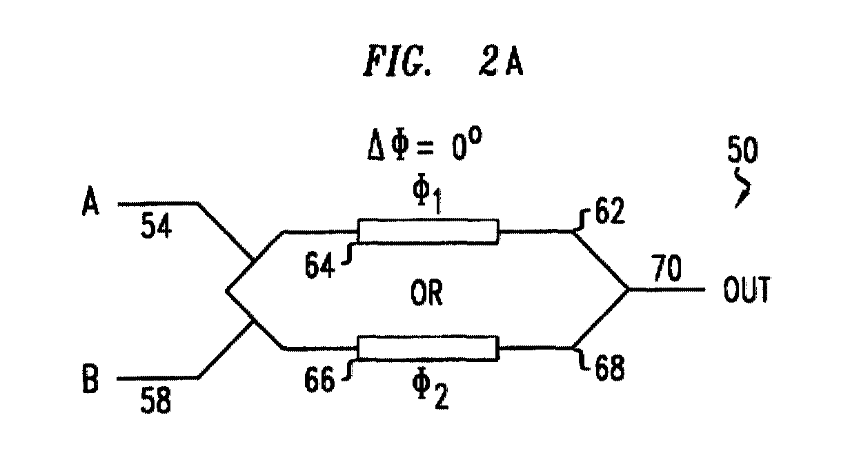
Referring to FIGS. 2(a) and 2(b), an optical logic device 50 for
performing a Boolean OR operation is shown according to an embodiment of
the present invention. Optical logic device 50 includes at least a first and a
second input, 54 and 58, for receiving at least a first and a second input
optical signal, A and B. Device 50 includes at least one waveguide. In one
embodiment, device 50 is formed from an MZI having a first and a second
waveguide, 62 and 68, for respectively receiving optical signals, A and B,
through inputs, 54 and 58.
-
Device 50 also includes an amplifier. In one embodiment, the
amplifier is realized by a first and a second semiconductor optical amplifier
("SOA"), 64 and 66. Each SOA is biased to operate in the saturation region.
For the purposes of the present invention, each SOA amplifies a received
optical signal while also induces a phase change. As is known to skilled
artisans, the phase change is controllable and results primarily from the
ratio of the refractive index of the waveguide to the amplification gain over
the SOA length. For more information, see Leuthold et al., "All-Optical
Space Switches with Gain and Principally Ideal Extinction Ratios," IEEE
Journal of Quantum Electronics, Vol. 34, No. 4 (April 1998) (hereinafter
"Leuthold I"), and Leuthold et al., "All-Optical Mach-Zehnder
Interferometer Wavelength Converters and Switches with Integrated Data
and Control Signal Separation Scheme," Journal of Lightwave Technology,
Vol. 17, No. 6 (June 1999) (hereinafter "Leuthold II"), hereby incorporated
by reference.
-
As shown, SOA 64 corresponds with waveguide 62, and SOA 66
corresponds with waveguide 68. Each SOA creates a phase delay, Φ1 and Φ2,
with respect to optical power propagating through its corresponding
waveguide. As such, input optical signal, A, propagates through waveguide
62 having a phase delay Φ1, while input optical signal, B, propagates
through waveguide 68 having a phase delay Φ2. Optical signals A and B are
combined at an output junction 70, where waveguides, 62 and 68, are
adjoined. A relative phase delay, ΔΦ, of zero (0°) degrees is created between
waveguides, 62 and 68, at output junction 70. Thus, when optical power
from both waveguides is present at output junction 70, it is in phase and
constructive interference will occur. The combination of optical signals A
and B creates an output signal OUT.
-
Device 50 performs a Boolean OR logic operation on binary input
signals A and B. The relationship between signals A, B, and OUT is
reflected in the truth table shown in FIG. 2(b). Functionally, when signals
A and B are both binary zeros, a null signal equivalent to a binary zero
propagates through both waveguides. At output junction 70, both null
signals are combined to generate a null output optical signal OUT
corresponding with a binary zero.
-
If only one input signal A or B is a null signal, while the other input
signal is a binary one, output optical signal OUT is equivalent to a binary
one. Here, the optical power associated with the binary one input optical
signal is combined with the null signal of the other input optical signal at
output junction 70. This combination results in an output signal OUT
equivalent to a binary one.
-
In the event both input optical signals A and B are binary ones,
optical power from each input signal propagates through both waveguides
with a corresponding phase delay. As the relative phase relative, ΔΦ,
between each waveguide is zero (0°) degrees, both input optical signals A
and B are in phase at output junction 70. Therefore, when the optical power
associated with both input optical signals is combined, constructive
interference creates an output signal OUT equivalent to a binary one. This
scenario is illustrated in FIG. 1(b) and the accompanying text herein.
-
Referring to FIGS. 3(a) and 3(b), an optical logic device 80 for
performing an XOR Boolean operation is shown according to an
embodiment of the present invention. Optical logic device 80 includes at
least a first and a second input, 84 and 88, for receiving at least a first and a
second input optical signal, A and B. Device 80 includes at least one
waveguide. In one embodiment, device 80 has a first and a second
waveguide, 92 and 98, for respectively receiving optical signals, A and B,
through inputs, 84 and 88.
-
Device 80 also includes an amplifier. In one embodiment, the
amplifier is realized by a first and a second semiconductor optical amplifier
("SOA"), 94 and 96. By this arrangement, SOA 94 corresponds with
waveguide 92 and SOA 96 corresponds with waveguide 98. Each SOA
creates a phase delay, Φ1 and Φ2, with respect to its corresponding
waveguide. As such, input optical signal, A, propagates through waveguide
92 having a phase delay Φ1, while input optical signal, B, propagates
through waveguide 98 having a phase delay Φ2. Optical signals A and B are
combined at an output junction 100, where waveguides, 62 and 68, are
adjoined. By this design, a relative phase delay, ΔΦ, of one hundred eighty
(180°) degrees is created between waveguides, 92 and 98, at output junction
100. Thus, when optical power from both waveguides is present at output
junction 100, it is out of phase and destructive interference will occur. The
combination of optical signals A and B creates an output signal OUT.
-
Device 80 performs a Boolean XOR logic function on binary input
signals A and B. The relationship between signals A, B, and OUT is
reflected in the truth table shown in FIG. 3(b). Functionally, when signals
A and B are both binary zeros, a null signal equivalent to a binary zero
propagates through both waveguides. At output junction 100, both null
signals are combined to generate a null output optical signal OUT
corresponding with a binary zero.
-
If only one input signal A or B is a null signal, while the other input
signal is a binary one, output optical signal OUT is equivalent to a binary
one. Here, the optical power associated with the binary one input optical
signal equal is combined with the null signal of the other input optical signal
at output junction 100. This combination results in an output signal OUT
equivalent to a binary one.
-
In the event both input optical signals A and B are binary ones,
optical power from each input signal propagates through both waveguides
with a corresponding phase delay. As the relative phase relative, ΔΦ,
between each waveguide is one hundred eighty (180°) degrees, both input
optical signals A and B are out of phase with respect to each other at output
junction 70. Therefore, when the optical power associated with both input
optical signals is combined, destructive interference creates an output signal
OUT equivalent to a binary zero. This scenario is illustrated in FIG. 1(a)
and the accompanying text herein.
-
Referring to FIGS. 4(a) and 4(b), an optical logic device 110 for
performing an AND Boolean operation is shown according to an
embodiment of the present invention. Optical logic device 110 includes at
least a first and a second input, 114 and 118, for receiving at least a first and
a second input optical signal, A and B, respectively. Device 110 includes at
least one waveguide. In one embodiment, device 110 has a first and a
second waveguide, 132 and 138.
-
Device 110 also includes an amplifier. In one embodiment, the
amplifier is realized by a first and a second semiconductor optical amplifier
("SOA"), 134 and 136. By this arrangement, SOA 134 corresponds with
waveguide 132 and SOA 138 corresponds with waveguide 138. Each SOA
creates a phase delay, Φ1 and Φ2, with respect to its corresponding
waveguide. As such, the optical signal propagating through waveguide 132
has a phase delay, Φ1, while the optical signal propagating through
waveguide 138 has a phase delay, Φ2. Optical signals A and B are combined
at an output junction 140, where waveguides, 132 and 138, are adjoined.
By this design, a relative phase delay, ΔΦ, of zero (0°) degrees is created
between waveguides, 132 and 138, at an output junction 140. Optical
signals A and B are combined at an output junction 140 to form an output
signal OUT, where waveguides, 132 and 138, are adjoined. Device 110
employs constructive or destructive interference at output junction 140,
depending on the binary values of the optical signals, as will be understood
from disclosure hereinbelow.
-
First and second inputs, 114 and 118, are coupled with waveguides,
132 and 138, through a power divider 130. Power divider 130 allocates a
portion of each input signal, 114 and 118, into each waveguide, 132 and
138. Power divider 130 includes a Y-junction device 142 and branches 120,
124, and 128. Y-junction devices are known to skilled artisans. For more
information, see Leuthold et al., "Multimode Interference Couples for the
Conversion and Combining of Zero and First Order Modes," Journal of
Lightwave Technology, Vol. 16, No. 7 (July 1998) (hereinafter "Leuthold
III"), hereby incorporated by reference. Y-junction device 142 includes a
multimode interference ("MMI") coupler having a single input port and at
least two output ports. MMI couplers are waveguide couplers for converting
a fundamental mode of optical power into a first order mode. MMI couplers
couple the first order mode with one or more output waveguides, depending
on the geometry of the MMI coupler. Operably, an input arm of the MMI
coupler is positioned such that the output waveguide(s) are in contact with
each other to form a wider waveguide for transmitting two optical beams in
the form of a first mode. Here, the MMI of Y-junction 142 is configured to
guide both a fundamental mode and a first order mode of optical power.
This is realized by widening and positioning the output of Y-junction 142 to
capture the desired fraction of optical power. See Leuthold III.
-
In one embodiment, power divider 130 allocates optical power by
thirds. Thus, if only input optical signal A corresponds with a binary one,
power divider 130 causes two-thirds (2/3) of the optical power associated
with input optical signal A to propagate through waveguide 132, and one-third
(1/3) to propagate through waveguide 138. Likewise, if only input
optical signal B corresponds with a binary one, two-thirds (2/3) of the
optical power, for example, propagates through waveguide 138, while one-thirds
(1/3) propagates through waveguide 132. To realize this distribution
of optical power, Y-junction 142 has a length measured from the inputs to
the outputs of the MMI coupler. In one embodiment, Y-junction 142 has an
end to end length in the approximate range of 0.5 mm to 1.0 mm
corresponding with the desired coupling fraction. Moreover, it should be
apparent to skilled artisans that when both input optical signals A and B
correspond with a binary one, an equal amount of the optical power is
distributed to waveguides 132 and 138 by power divider 130.
-
Device 110 performs a Boolean AND logic function on binary input
signals A and B. The relationship between signals A, B, and OUT is
reflected in the truth table shown in FIG. 4(b). Functionally, when signals
A and B are both binary zeros, null signals propagate from inputs 114 and
118 through waveguides 132 and 138. At output junction 140, both null
signals from waveguides 132 and 138 are combined to generate a null
output optical signal OUT set to a binary zero.
-
If only one input signal, A or B, is a null signal while the other input
signal, B or A, is a binary one, output signal OUT is set to a binary zero. The
optical power from the binary one input signal is divided by the power
divider 130, as detailed hereinabove. The distribution of optical power
along waveguides 132 and 138 induces an additional relative phase shift of
one hundred eighty (180°) degrees. This additional relative phase shift is
created by the respective SOA of the waveguide receiving one-third (1/3) of
the optical power associated with the binary one input signal. See generally
Leuthold I and Leuthold II. In one embodiment, each SOA is configured to
trigger the additional relative phase shift (180°) in response to receiving
optical power of approximately 1 mW. This optical power corresponds with
the distribution of one-third (1/3) of the optical power from a binary one
input signal. The distribution between waveguides 132 and 138 of the
optical power from the one input signal set to a binary one causes destructive
interference at output junction 140. The resultant destructive interference,
given the power differences propagating through waveguides 132 and 138,
will form residue power corresponding with a binary zero. As a result, an
output signal OUT created at output junction 140 is equivalent to a binary
zero.
-
In the event both input optical signals A and B are binary ones,
optical power from each input signal equally propagates through waveguides
132 and 138. With the relative phase shift, ΔΦ, between the waveguides
being zero (0°) degrees, both input optical signals A and B are in phase with
respect to each other at output junction 140. Moreover, waveguides 132
and 138 are balanced such that the optical power propagating through both
is being equal. As such, an additional relative phase shift is not induced.
Therefore, the optical power associated with both input optical signals is
combined using the principles of interference to create an output signal
OUT equivalent to a binary zero.
-
Referring to FIGS. 5(a) and 5(b), an optical logic device or inverter
150 for performing a NOT Boolean operation is shown according to an
embodiment of the present invention. Optical logic device 150 includes at
least a first input 154 for receiving at least a first input optical signal A.
Device 150 also receives a control optical signal CLOCK at a second input
158. Control signal CLOCK is a stream of optical bits corresponding with a
binary one. Moreover, the stream of optical bits is set to the maximum
computational bit rate of optical logic devices employing the present
invention, as stated hereinabove.
-
Optical logic device 150 includes at least one waveguide. In one
embodiment, device 150 has a first and a second waveguide, 162 and 168.
First and a second waveguides, 162 and 168, respectively receive optical
signals, A and CLOCK, through inputs, 154 and 158. Device 150 also has
an amplifier. In one embodiment, the amplifier is realized by a first and a
second semiconductor optical amplifier ("SOA"), 164 and 166. By this
arrangement, SOA 164 corresponds with waveguide 162 and SOA 166
corresponds with waveguide 168. Each SOA creates a phase delay, Φ1 and
Φ2, with respect to its corresponding waveguide. As such, input optical
signal, A, propagates within waveguide 162 having a phase delay Φ1, while
control optical signal, CLOCK, propagates within waveguide 168 having a
phase delay Φ2. Optical signals A and CLOCK are combined at an output
junction 170, where waveguides, 162 and 168, are adjoined. By this design,
a relative phase delay, ΔΦ, of one hundred eighty (180°) degrees is created
between waveguides, 162 and 168, at output junction 170. If optical power
from both waveguides is present at output junction 170, it is out of phase
and destructive interference will occur. The combination of input optical
signal, A, in the presence of control signal, CLOCK, creates an output signal
OUT.
-
Device 150 performs a Boolean NOT logic function on binary input
signal A. The relationship between input signal A and output signal OUT is
reflected in the truth table shown in FIG. 5(b). If input signal A is a binary
zero, output optical signal OUT is equivalent to a binary one. Here, the null
signal equivalent to a binary zero propagates through waveguide 162, while
the stream of binary ones from control signal, CLOCK, propagate through
waveguide 168. At output junction 170, the combination of the binary zero
null signal with the binary one of control signal, CLOCK, results in an
output optical signal OUT equivalent to a binary one.
-
In the event input optical signal A is a binary one, optical power from
signals A and CLOCK propagate through waveguides 162 and 168. As the
relative phase, ΔΦ, between each waveguide is one hundred eighty (180°)
degrees, signals A and CLOCK are out of phase with respect to each other at
output junction 170. Therefore, when the optical power associated with
both input optical signals is combined, destructive interference creates an
output signal OUT equivalent to a binary zero.
-
Optical logic device 150 enables the design of various additional
Boolean operations in view of the other embodiments detailed hereinabove.
As such, it will become apparent to skilled artisans that a Boolean NOR
operation may be realized by combining OR logic gate 50 of FIG. 2 with
NOT logic device 150. Likewise, employing NOT logic device 150 with XOR
logic device 80 of FIG. 3 enables an X-NOR logic device. Combining the
AND logic device 110 of FIG. 4 with the NOT logic operation of device 150
yields a NAND logic function.
-
Referring to FIGS. 6(a) and 6(b), an optical logic device 175 for
performing a Boolean OR operation is shown according to another
embodiment of the present invention. Device 175, in contrast to the optical
logic device 50 of FIG. 2(a), relies on a Michelson interferometric
configuration for performing a Boolean OR logic function. Operatively,
device 175 functions in a similar manner to optical logic device 50. Other
arrangements and alternative interferometric schemes will become apparent
to skilled artisans upon reviewing the disclosure herein.
-
Referring to FIGS. 7(a) and 7(b), an optical two-bit binary adder
200 is shown according to another embodiment of the present invention.
Two-bit binary adders are generally known. See Hill, pp. 175-182. Binary
adder 200 includes an optical device 210 for performing a Boolean XOR
operation, and an optical device 220 for performing a Boolean AND
operation. Binary adder 200 employs Boolean logic devices detailed herein
as building blocks. In one embodiment of the present invention, optical
device 210 is realized by XOR gate 80 of FIG. 3, while optical device 220 is
realized by AND gate 110 of FIG. 4. Adder 200 performs binary addition
on binary signals A and B to create output signals SUM and CARRY. A
truth table corresponding with functionality of two-bit binary adder 200 is
shown in FIG. 7(b).
-
It should be noted that the hereinabove optical logic devices may be
combined to form computational devices, such as sequential circuits, flip
flops, decoders, parity checkers, shift registers, linear feedback shift
registers, linear congruential generators, counters, multiplexers,
demultiplexers, pseudo-random number generators, state machines, and
arithmetic logic units, for example. For more information on these
computational devices, see Buchsbaum, Encyclopedia of Integrated Circuits,
Prentice-Hall 1981, hereby incorporated by reference. See also Hill and
Koopman.
-
Referring to FIGS. 8(a) and 8(b), an optical arithmetic device 250
is shown according to another embodiment of the present invention.
Arithmetic device 250 includes optical devices 260 and 280 for performing
XOR operations, optical devices 270 and 290 for performing AND
operations, and an optical device 300 for performing an OR operation.
Arithmetic device 250 is realized by a combination of Boolean logic devices
detailed herein as building blocks. In one embodiment, optical devices 260
and 280 are realized from device 80 of FIG. 3, optical devices 270 and
290 are realized from optical device 110 of FIG. 4, and optical device 300
is realized from optical device 50 of FIG. 2.
-
As configured in FIG. 8(a), arithmetic device 250 is designed to
function as a full three-bit adder. Full three-bit adders are a fundamental
element in computational processing, and are generally known. See Hill, pp.
175-182. Arithmetic device 250 performs binary addition on binary signals
A, B, and C, to create output signals SUM and CARRY. A truth table
corresponding with functionality of three-bit binary adder 250 is shown in
FIG. 8(b). Arithmetic device 250 may also be configured to perform other
mathematical processes, including subtraction, multiplication, division, as
well as trigonometric operations on any number of bits.
-
Referring to FIG. 9, an optical device 350 for encrypting data is
shown according to another embodiment of the present invention.
Encryption device 350 is realized by an optical key generator 360 and an
optical encryptor 370. Key generator 360 is a number generator used in
cryptographically securing the one way transmission of data as detailed
hereinabove. See Schneier and Koopman. Generator 360 may be realized
using various configurations known to skilled artisans, such as a linear
feedback shift register ("LFSR"), for example. In one embodiment, optical
key generator 360 comprises a number of optical logic devices as building
blocks for generating an optical key. The optical logic devices forming
generator 360 may be realized from the embodiments of the present
invention detailed hereinabove.
-
Generator 360 creates an output KEY in response to receiving a
trigger or clock signal, CLOCK, and an initial number, INITIAL
NUMBER, as is known to skilled artisans. See Schneier and Koopman.
Optical encryptor 370 receives the optical KEY signal of key generator 360
and a stream of data signals, DATA. In response, encryptor 370 generates
an ENCRYPTED DATA output. In a further embodiment, optical
encryptor 370 also receives an optical signal KEY' from key generator 360.
Optical signal KEY' is a phase delayed version of optical signal KEY. The
relative phase delay between optical signal KEY and optical signal KEY'
corresponds with the bit width of the data from the optical stream of data
signals, DATA.
-
Upon receiving bits from the optical stream of data signals, DATA,
and optical signal KEY, encryptor 370 performs an encryption operation
similar to bit flipping. Here, optical signal KEY' acts as reset mechanism for
resetting encryptor 370. The optical power of signal KEY is set to initiate
an additional phase shift of one hundred eighty (180°) degrees to the relative
phase relative, ΔΦ, between each waveguide. As such, if a binary one bit
from optical signal KEY is received, the additional phase delay creates an
effective phase delay of zero (0°) degrees at the output junction.
-
In the above scenario, the optical stream of data signals, DATA, split
equally between both waveguides of the encryptor 370, are constructively
added at the output junction. However, optical signal KEY' is set to initiate
an additional phase shift of one hundred eighty (180°) degrees. Thus, upon
receiving optical signal KEY', destructive interference is created at the
output junction, causing the optical stream of data signals, DATA.
-
Referring to FIG. 10, a three port interferometer based, Boolean logic
device 400 is shown according to another embodiment of the present
invention. Device 400 is approximately 5 mm long, from the input ports to
the output ports of the interferometer. Device 400 employed a first and a
second waveguide, 412 and 416. Waveguides, 412 and 416, are
approximately 0.4 mm long, from the output of a first SOA, 424 or 432, to
the input of a second SOA, 428 or 436, respectively. Waveguides, 412 and
416, each received an input optical signal at the inputs 404 and 408,
respectively.
-
Waveguides, 412 and 416, are formed on a single substrate 440 of
indium phosphide (InP). Each of the SOAs is monolithically integrated
within their respective waveguides. The SOAs were formed from In1-
xGaxAsyP1-y, where x=0.4 and y=0.85, sandwiched between an n-doped and
p-doped cladding layers of indium and phosphorus (InP). The p doping
levels were approximately 2x10¹⁷, while the n doping levels were
approximately 2x10¹⁸. Mesas were formed to define active regions of the
SOA.
-
In one embodiment, the device of the present invention is formed by
two splitters - MMI couplers - for dividing and combining the optical data
signals, two couplers - MMI couplers - for introducing the control signals,
and the SOAs for providing the necessary nonlinearity for switching. The
SOAs may be placed on the MZI arms to ease control of the on-off states.
The SOAs are grown by a two-step Metal Organic Vapor Phase Epitaxy
process on the InP substrate. Initially, 1.55um-InGaASP active SOA layers
approximately 0.22 µm thick are grown. Subsequently the region outside
the 500 - 1500 µm long SOA areas are etched, and the passive waveguide
layer is grown - first a 0.6 µm thick 1.28 µm -InGaAsP layer, and a 1.6 µm
thick InP cladding layer thereafter. The waveguides are then formed by
etching into the SOA and waveguide heterostructure. The 2x2-MMI
structures are advantageously etched during the formation of the
waveguides and are 200 µm by 11.3 µm. A heavily doped InGaAs layer is
then placed on top of the waveguide sections to provide contacts with gold
pads. The resultant chip size of the device is approximately 6 x 1.0 mm. It
should be noted that the waveguide facets are antireflection coated, while the
chip is thinned to allow heat dissipation and ease of cleaving.
-
Waveguides 412 and 416 each include a pair of SOAs, 424/428 and
432/436. Each SOA had a length approximately in the range of 600 µm to
1200 µm. Moreover, each SOA consumed approximately 300 mW of power,
and had a gain of approximately 25 dB at room temperature for an optical
signal operating approximately at a wavelength of 1550 nm.
-
Through a Y-junction coupler 438 formed from an MMI, waveguides
412 and 416 adjoin at an output junction 420. The MMI is approximately
0.5 mm long, measured from end to end, to capture the desired proportional
optical power from waveguides, 412 and 416. As a result, an output signal
444 propagated through output junction 420.
-
As detailed hereinabove, device 400 employs constructive or
destructive interference at junction 420 in formulating output signal 444.
The interference created is dependent on relative phase differences created
by the SOAs. The selection of the relative phase differences determines, in
part, the Boolean logic operation to be performed.
-
Given the above arrangement, the switching speed has been observed
to be approximately 10 picoseconds. This result, however, is limited by the
change in carrier density in each of the SOAs following the arrival of optical
power. The change in carrier density, however, is generally directly
proportional to the wavelength of the optical power. In present example, the
change in carrier density is minimal given the narrow operable wavelength
range of the optical signals.