EP1169673B1 - Method for determining the position of a vehicle - Google Patents
Method for determining the position of a vehicle Download PDFInfo
- Publication number
- EP1169673B1 EP1169673B1 EP00916799A EP00916799A EP1169673B1 EP 1169673 B1 EP1169673 B1 EP 1169673B1 EP 00916799 A EP00916799 A EP 00916799A EP 00916799 A EP00916799 A EP 00916799A EP 1169673 B1 EP1169673 B1 EP 1169673B1
- Authority
- EP
- European Patent Office
- Prior art keywords
- container
- vehicle
- supports
- crane
- container crane
- Prior art date
- Legal status (The legal status is an assumption and is not a legal conclusion. Google has not performed a legal analysis and makes no representation as to the accuracy of the status listed.)
- Expired - Lifetime
Links
- 238000000034 method Methods 0.000 title claims abstract description 9
- 238000001514 detection method Methods 0.000 abstract description 2
- 238000011156 evaluation Methods 0.000 description 7
- 238000002604 ultrasonography Methods 0.000 description 1
Images


Classifications
-
- B—PERFORMING OPERATIONS; TRANSPORTING
- B66—HOISTING; LIFTING; HAULING
- B66C—CRANES; LOAD-ENGAGING ELEMENTS OR DEVICES FOR CRANES, CAPSTANS, WINCHES, OR TACKLES
- B66C13/00—Other constructional features or details
- B66C13/18—Control systems or devices
- B66C13/46—Position indicators for suspended loads or for crane elements
-
- G—PHYSICS
- G01—MEASURING; TESTING
- G01S—RADIO DIRECTION-FINDING; RADIO NAVIGATION; DETERMINING DISTANCE OR VELOCITY BY USE OF RADIO WAVES; LOCATING OR PRESENCE-DETECTING BY USE OF THE REFLECTION OR RERADIATION OF RADIO WAVES; ANALOGOUS ARRANGEMENTS USING OTHER WAVES
- G01S17/00—Systems using the reflection or reradiation of electromagnetic waves other than radio waves, e.g. lidar systems
- G01S17/88—Lidar systems specially adapted for specific applications
-
- G—PHYSICS
- G01—MEASURING; TESTING
- G01S—RADIO DIRECTION-FINDING; RADIO NAVIGATION; DETERMINING DISTANCE OR VELOCITY BY USE OF RADIO WAVES; LOCATING OR PRESENCE-DETECTING BY USE OF THE REFLECTION OR RERADIATION OF RADIO WAVES; ANALOGOUS ARRANGEMENTS USING OTHER WAVES
- G01S5/00—Position-fixing by co-ordinating two or more direction or position line determinations; Position-fixing by co-ordinating two or more distance determinations
- G01S5/16—Position-fixing by co-ordinating two or more direction or position line determinations; Position-fixing by co-ordinating two or more distance determinations using electromagnetic waves other than radio waves
Definitions
- the invention relates to a method for determining the position of a vehicle according to the preamble of the first claim.
- the invention is applicable wherever vehicles, preferably portal stacker, too a container crane must be placed in an exact position so that a Repositioning the container crane does not have to be done.
- Container cranes are special container bridges for unloading ships as well Stacking cranes in a container warehouse. So far, the container envelope has been Container cranes or portal stackers executed only in manual mode. In the Load transfer to the container crane, the driver of the transport vehicle has the Task of placing the container approximately midway under the container crane. to Load pick up by the container crane is usually repositioned. For Fully automatic container cranes now set themselves the task of transferring the load Always position the transport vehicle exactly in the middle of the container crane that post-lifting by the container crane is not required. This assumes that the transport vehicle on the container crane so accurate oriented that a precise settling of the container is possible.
- a device for determining the position of a vehicle relative to a container lifting device in which at least two ultrasound-based sensors with parallel aligned axes occupy an unchanged position with respect to a frame of the lifting device, the transport vehicle reflectors evaluation means are coupled to a detection device and retaining marks are required to perform the positioning.
- a disadvantage of this method is u. a. that for the sake of orientation means, such as holding marks, Reflectors o. ⁇ ., Must be attached to the position of the Transport vehicle or the container to capture.
- the task is therefore to develop a procedure with which a transport vehicle, preferably a portal stacker, opposite to a Container crane oriented, without having to be attached to this markings, so that an automatic operation of the vehicle is ensured, in which the Position of the vehicle relative to the container crane is always known exactly.
- the inventive method for determining the position of a vehicle relative to a container crane based on the basis that container cranes in the field of Support a prominent contour through the columns up to a certain height exhibit.
- the vehicle for example, a Portal stacker
- orient For orientation it is necessary that, for example the portal stacker has a scanning device.
- This scanner for example a Laser scanner, can be arranged on the upper edge of the portal stacker in the direction of travel be.
- the laser scanner turns the supports of the gantry crane into positioning aids detected. This can be done by the scanner angle and distance of the supports of the Portal crane recorded and passed on to an evaluation computer.
- the software of The evaluation computer contains data about the contour of the columns of the container crane and thus determines the exact position of the transport vehicle relative to the supports of the Container crane.
- FIG. 1 shows in three views a portal stacker 2 on which a laser scanner 3 is arranged in the search field, the supports of a container crane 1 are located, wherein the portal stacker is in front of the container crane 1.
- the laser beam 4 detects two Supporting the gantry crane 1 at the level of the upper edge of the portal stacker 2.
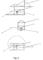
- position of the portal stacker 2 are first the front supports of the Portal crane 1 recorded and stored. To the rear supports of the gantry crane 1 to capture, moves the portal stacker 2 in the position shown in Fig. 2.
- the portal stacker continuously via the data passing through the laser scanner to the position of the Container crane supports get to the evaluation computer, work.
- the schematic Representation of the function of the evaluation computer is shown in FIG. 3.
- the laser scanner 3 reads 5 continuous data 6, the front support 7 and the rear support 8, respectively affect.
- This data is stored 9, from which the position of the vehicle is determined 10.
- the distance of the vehicle is determined to the destination 11.
- actual position 12 is at a predetermined target position 13 compared.
- a positioning controller 14 constantly compares in this way recorded data with the given data.
- the positioning controller 14 acts on the Drive control 15 and the traction drive 16 until the data of the desired position 13 coincide with the data of the actual position 12.
- the portal stacker has to be 2 Target reached and can settle the container in the desired position.
Landscapes
- Engineering & Computer Science (AREA)
- Physics & Mathematics (AREA)
- Electromagnetism (AREA)
- General Physics & Mathematics (AREA)
- Radar, Positioning & Navigation (AREA)
- Remote Sensing (AREA)
- Computer Networks & Wireless Communication (AREA)
- Mechanical Engineering (AREA)
- Automation & Control Theory (AREA)
- Control And Safety Of Cranes (AREA)
- Electric Propulsion And Braking For Vehicles (AREA)
- Iron Core Of Rotating Electric Machines (AREA)
- Devices For Checking Fares Or Tickets At Control Points (AREA)
- Warehouses Or Storage Devices (AREA)
- Vehicle Body Suspensions (AREA)
- Character Spaces And Line Spaces In Printers (AREA)
- Control Of Position, Course, Altitude, Or Attitude Of Moving Bodies (AREA)
Abstract
Description
Die Erfindung betrifft ein Verfahren zur Bestimmung der Lage eines Fahrzeuges entsprechend dem Oberbegriff des 1. Patentanspruches.The invention relates to a method for determining the position of a vehicle according to the preamble of the first claim.
Die Erfindung ist überall dort anwendbar, wo Fahrzeuge, vorzugsweise Portalstapler, zu einem Containerkran in eine genaue Position gebracht werden müssen, so dass ein Nachpositionieren des Containerkranes nicht erfolgen muss.The invention is applicable wherever vehicles, preferably portal stacker, too a container crane must be placed in an exact position so that a Repositioning the container crane does not have to be done.
Containerkrane sind spezielle Containerbrücken zur Schiffsentladung als auch Stapelkrane in einem Containerlager. Bisher wurde der Containerumschlag mit Containerkranen bzw. Portalstaplern nur im Handbetrieb ausgeführt. Bei der Lastübergabe an den Containerkran hat der Fahrer des Transportfahrzeuges die Aufgabe, den Container ungefähr mittig unter dem Containerkran abzusetzen. Zur Lastaufnahme durch den Containerkran wird dieser in der Regel nachpositioniert. Für vollautomatische Containerkrane stellt sich nun die Aufgabe, zur Lastübergabe das Transportfahrzeug immer genau mittig unter dem Containerkran zu positionieren, so dass zur Lastaufnahme durch den Containerkran kein Nachpositionieren erforderlich ist. Das setzt voraus, dass sich das Transportfahrzeug an dem Containerkran so genau orientiert, dass ein exaktes Absetzen des Containers möglich ist.Container cranes are special container bridges for unloading ships as well Stacking cranes in a container warehouse. So far, the container envelope has been Container cranes or portal stackers executed only in manual mode. In the Load transfer to the container crane, the driver of the transport vehicle has the Task of placing the container approximately midway under the container crane. to Load pick up by the container crane is usually repositioned. For Fully automatic container cranes now set themselves the task of transferring the load Always position the transport vehicle exactly in the middle of the container crane that post-lifting by the container crane is not required. This assumes that the transport vehicle on the container crane so accurate oriented that a precise settling of the container is possible.
Aus DE 36 06 363 ist eine Einrichtung zur Bestimmung der Lage eines Fahrzeuges relativ zu einer Containerhebevorrichtung bekannt, bei der mindestens zwei auf der Basis von Ultraschall arbeitenden Sensoren mit parallel ausgerichteten Achsen eine unveränderte Position in Bezug auf ein Gerüst der Hebevorrichtung einnehmen, das Transportfahrzeug Reflektoren aufweist, Auswerteeinrichtungen mit einem Erkennenungsgerät gekoppelt sind und Haltemarken benötigt werden, um die Positionierung durchzuführen.From DE 36 06 363 a device for determining the position of a vehicle relative to a container lifting device is known in which at least two ultrasound-based sensors with parallel aligned axes occupy an unchanged position with respect to a frame of the lifting device, the transport vehicle reflectors evaluation means are coupled to a detection device and retaining marks are required to perform the positioning.
Nachteilig an dieser Methode ist u. a., dass zur Oientierung Mittel, wie Haltemarken, Reflektoren o. Ä., angebracht werden müssen, um die Position des Transportfahrzeuges oder des Containers zu erfassen.A disadvantage of this method is u. a. that for the sake of orientation means, such as holding marks, Reflectors o. Ä., Must be attached to the position of the Transport vehicle or the container to capture.
Aufgabe ist es daher, ein Verfahren zu entwickeln, mit dem sich ein Transportfahrzeug, vorzugsweise ein Portalstapler, gegenüber einem Containerkran orientiert, ohne dass an diesem Markierungen angebracht sein müssen, so dass ein automatischer Betrieb des Fahrzeuges gewährleistet ist, bei dem die Position des Fahrzeuges gegenüber dem Containerkran immer exakt bekannt ist. The task is therefore to develop a procedure with which a transport vehicle, preferably a portal stacker, opposite to a Container crane oriented, without having to be attached to this markings, so that an automatic operation of the vehicle is ensured, in which the Position of the vehicle relative to the container crane is always known exactly.
Diese Aufgabe wird nach den Merkmalen des 1. Patentanspruches gelöst. Unteransprüche geben vorteilhafte Ausführungen der Erfindung wieder.This object is achieved according to the features of the first claim. Subclaims give advantageous embodiments of the invention again.
Das erfindungsgemäße Verfahren zur Bestimmung der Lage eines Fahrzeuges relativ zu einem Containerkran basiert auf der Grundlage, dass Containerkrane im Bereich der Stützen durch die Stützen bis zu einer bestimmten Höhe eine markante Kontur aufweisen. An dieser markanten Kontur kann sich das Fahrzeug, beispielsweise ein Portalstapler, orientieren. Für die Orientierung ist es erforderlich, dass beispielsweise der Portalstapler eine Scaneinrichtung aufweist. Dieser Scanner, beispielsweise eine Laserscanner, kann an der Oberkante des Portalstaplers in Fahrtrichtung angeordnet sein. Durch den Laserscanner werden die Stützen des Portalkranes als Positionierhilfen erfasst. Das kann geschehen, indem der Scanner Winkel und Abstand der Stützen des Portalkranes erfasst und an einen Auswerterechner weitergibt. Die Software des Auswerterechners beinhaltet Daten über die Kontur der Stützen des Containerkranes und ermittelt so die exakte Lage des Transportfahrzeuges relativ zu den Stützen des Containerkranes.The inventive method for determining the position of a vehicle relative to a container crane based on the basis that container cranes in the field of Support a prominent contour through the columns up to a certain height exhibit. At this striking contour, the vehicle, for example, a Portal stacker, orient. For orientation it is necessary that, for example the portal stacker has a scanning device. This scanner, for example a Laser scanner, can be arranged on the upper edge of the portal stacker in the direction of travel be. The laser scanner turns the supports of the gantry crane into positioning aids detected. This can be done by the scanner angle and distance of the supports of the Portal crane recorded and passed on to an evaluation computer. The software of The evaluation computer contains data about the contour of the columns of the container crane and thus determines the exact position of the transport vehicle relative to the supports of the Container crane.
Nachdem mittels Auswerterechner die Ist-Position des Portalstaplers bestimmt wurde, erfolgt ein Vergleich mit der Soll-Position, in die ein Container gebracht werden soll. Mittels Fahrantrieb und Antriebssteuerung und einem laufenden Vergleich von Ist- und Soll-Daten über einen Positionsregler verkehrt das Fahrzeug mit dem Container so lange in die gewünschte Position, bis die Daten von Soll-Position und Ist-Position übereinstimmen. Eine Orientierung erfolgt dabei laufend über die vom Scanner erfassten Daten der Stützen des Containerkranes.After the actual position of the portal stacker has been determined by means of an evaluation computer, a comparison is made with the desired position into which a container is to be brought. By means of travel drive and drive control and an ongoing comparison of actual and Target data via a position controller reverses the vehicle with the container long in the desired position until the data of target position and actual position to match. An orientation takes place continuously over that of the scanner recorded data of the supports of the container crane.
Vorteilhaft ist es für das Verfahren, wenn mehrere Laserscanner am Fahrzeug angeordnet sind. Diese können senkrecht oder waagerecht angeordnet sein. Entscheidend ist, dass ihre Position gegenüber dem Fahrzeug abgeglichen ist. Vorteilhaft ist es jedoch, die Laserscanner waagerecht am Fahrzeug anzubringen in einer Höhe, in der ein eindeutiges Orientieren an den Containerkranstützen möglich ist.It is advantageous for the process when multiple laser scanners on the vehicle are arranged. These can be arranged vertically or horizontally. The decisive factor is that their position is aligned with the vehicle. However, it is advantageous to mount the laser scanner horizontally on the vehicle a height in which a clear orientation on the container crane supports is possible.
Im Folgenden soll die Erfindung an einem Ausführungsbeispiel und 3 Figuren näher erläutert werden. Die Figuren zeigen:
- Fig. 1
- Schematische Darstellung einer Containerbrücke und eines Portalstaplers mit Laserscanner bei der Anfahrt auf eine Containerbrücke in drei Ansichten;
- Fig. 2
- schematische Darstellung einer Containerbrücke und eines Portalstaplers mit Laserscanner in drei Ansichten bei einer Positionierung unter einer Containerbrücke;
- Fig. 3
- schematische Darstellung der Funktion des Auswerterechners.
- Fig. 1
- Schematic representation of a container bridge and a portal stacker with laser scanner when approaching a container bridge in three views;
- Fig. 2
- schematic representation of a container bridge and a portal stacker with laser scanner in three views when positioned under a container bridge;
- Fig. 3
- schematic representation of the function of the evaluation computer.
Die Fig. 1 zeigt in drei Ansichten einen Portalstapler 2, auf dem ein Laserscanner 3
angeordnet ist, in dessen Suchfeld sich die Stützen eines Containerkranes 1 befinden,
wobei der Portalstapler vor dem Containerkran 1 steht. Der Laserstrahl 4 erfasst zwei
Stützen des Portalkranes 1 in Höhe der oberen Kante des Portalstaplers 2. In der in Fig.
1 gezeigten Position des Portalstaplers 2 werden zunächst die vorderen Stützen des
Portalkranes 1 erfasst und gespeichert. Um die hinteren Stützen des Portalkranes 1 zu
erfassen, verfährt der Portalstapler 2 in die Position, die in Fig. 2 gezeigt wird. Nach
diesen beiden Stellungen des Portalstaplers, in denen dieser seine eigene Position
gegenüber den Stützen des Containerkranes bestimmt, kann der Portalstapler
kontinuierlich über die Daten, die über den Laserscanner zur Position der
Containerkranstützen an den Auswerterechner gelangen, arbeiten. Die schematische
Darstellung der Funktion des Auswerterechners zeigt die Fig. 3. Der Laserscanner 3
liest 5 kontinuierliche Daten 6 ein, die die vordere Stütze 7 bzw. die hintere Stütze 8
betreffen. Diese Daten werden abgespeichert 9, woraus die Position des Fahrzeuges
bestimmt wird 10. Weiterhin wird der Abstand des Fahrzeuges zum Ziel bestimmt 11.
Die auf diese Weise gewonnene Ist-Position 12 wird mit einer vorgegebenen Soll-Position
13 verglichen. Ein Positionierregler 14 vergleicht auf diese Weise ständig die
erfassten Daten mit den vorgegebenen Daten. Der Positionierregler 14 wirkt auf die
Antriebssteuerung 15 bzw. den Fahrantrieb 16 so lange, bis die Daten der Soll-Position
13 mit den Daten der Ist-Position 12 übereinstimmen. Dann hat der Portalstapler 2 sein
Ziel erreicht und kann den Container in der gewünschten Position absetzen. FIG. 1 shows in three views a
- 11
- Containerkrancontainer crane
- 22
- Portalstaplerstraddle
- 33
- Laserscanner / ScannerLaser scanner / scanner
- 44
- Laserstrahllaser beam
- 55
- Einlesen von DatenReading data
- 66
- Scannerdatenscanner data
- 77
- Einlesen von Daten der vorderen StützeReading data from the front support
- 88th
- Einlesen von Daten der hinteren StützeReading data from the rear support
- 99
- abgespeicherte Daten der Stützenstored data of the supports
- 1010
- Konturen suchen und PositionsbestimmungLook for contours and position determination
- 1111
- Abstand des Fahrzeuges zum ZielDistance of the vehicle to the destination
- 1212
- Ist-PositionActual position
- 1313
- Soll-PositionNominal position
- 1414
- Positionsreglerposition controller
- 1515
- Antriebssteuerungdrive control
- 1616
- Fahrantriebtraction drive
Claims (2)
- Method of determining the position of a vehicle (2), preferably a portal stacker (2), relative to a container crane (1), wherein a sensor (3) serves to determine the position of the vehicle (2), and evaluating devices are connected to a detector, characterised in that the supports of a container crane (1) are picked-up as positioning aids, in respect of angle and spacing, by means of at least one scanner (3), which is disposed on the vehicle, and the picked-up data is passed to the evaluating device, which compares these signals with signals provided in its program and hence determines the exact position of the vehicle relative to the supports of the container, the vehicle being displaceable into an exactly predetermined desired position relative to the supports of the container on the basis of this determination.
- Method according to claim 1, characterised in that the evaluating device memorises the contour of any desirable container systems.
Applications Claiming Priority (3)
| Application Number | Priority Date | Filing Date | Title |
|---|---|---|---|
| DE19916999 | 1999-04-15 | ||
| DE19916999A DE19916999A1 (en) | 1999-04-15 | 1999-04-15 | Positioning system for container stacking trucks uses laser scanner to avoid adjusting crane |
| PCT/DE2000/000687 WO2000063755A1 (en) | 1999-04-15 | 2000-03-03 | Method for determining the position of a vehicle |
Publications (2)
| Publication Number | Publication Date |
|---|---|
| EP1169673A1 EP1169673A1 (en) | 2002-01-09 |
| EP1169673B1 true EP1169673B1 (en) | 2003-07-09 |
Family
ID=7904646
Family Applications (1)
| Application Number | Title | Priority Date | Filing Date |
|---|---|---|---|
| EP00916799A Expired - Lifetime EP1169673B1 (en) | 1999-04-15 | 2000-03-03 | Method for determining the position of a vehicle |
Country Status (9)
| Country | Link |
|---|---|
| US (1) | US6571172B1 (en) |
| EP (1) | EP1169673B1 (en) |
| JP (1) | JP3665743B2 (en) |
| AT (1) | ATE244905T1 (en) |
| DE (2) | DE19916999A1 (en) |
| DK (1) | DK1169673T3 (en) |
| ES (1) | ES2203442T3 (en) |
| PT (1) | PT1169673E (en) |
| WO (1) | WO2000063755A1 (en) |
Families Citing this family (13)
| Publication number | Priority date | Publication date | Assignee | Title |
|---|---|---|---|---|
| WO2002034663A1 (en) * | 2000-10-27 | 2002-05-02 | Abb Ab | Chassis alignment system |
| US7123132B2 (en) | 2001-10-26 | 2006-10-17 | Abb Ab | Chassis alignment system |
| DE202004013306U1 (en) * | 2004-08-04 | 2005-12-15 | Liebherr-Werk Ehingen Gmbh | Device for detecting positions of a movably guided part |
| DE102006035929B4 (en) * | 2006-07-31 | 2013-12-19 | Götting KG | Method for sensor-assisted driving under an object or for entering an object with a utility vehicle |
| DE202007016156U1 (en) * | 2007-11-16 | 2008-03-20 | Noell Mobile Systems Gmbh | Portal forklift with automatic steering |
| DE102007060856A1 (en) * | 2007-12-18 | 2009-07-09 | Siemens Ag | Lane determining method, involves determining stopping point of movable objects e.g. lorry, with sensor arrangement, and determining lanes from stopping points of movable objects with statistic process |
| DE102008011539B3 (en) * | 2008-02-28 | 2009-06-18 | Noell Mobile Systems Gmbh | Fully automatic straddle carrier with local radiolocation and laser steering |
| US8451139B2 (en) * | 2010-02-22 | 2013-05-28 | Cnh America Llc | System and method for coordinating harvester and transport vehicle unloading operations |
| FI122666B (en) * | 2011-05-10 | 2012-05-15 | Cargotec Finland Oy | A system for determining the position of a container in a vehicle loaded with containers and / or its trailer |
| CN102381631A (en) * | 2011-09-16 | 2012-03-21 | 沈阳大学 | Intelligent positioning equipment connected between crane and transport vehicle |
| FI130426B (en) | 2014-06-30 | 2023-08-23 | Konecranes Oyj | Load transport by means of load handling equipment |
| JP6751603B2 (en) * | 2016-06-24 | 2020-09-09 | 株式会社Ihiエアロスペース | Container terminal system |
| CN112897345B (en) * | 2021-01-27 | 2023-06-23 | 上海西井信息科技有限公司 | Alignment method of container truck and crane and related equipment |
Family Cites Families (14)
| Publication number | Priority date | Publication date | Assignee | Title |
|---|---|---|---|---|
| DE3606363C2 (en) * | 1986-02-27 | 1995-04-13 | Vulkan Kocks Gmbh | Device for determining the position of a vehicle relative to a container lifting device |
| GB8822795D0 (en) * | 1988-09-28 | 1988-11-02 | Gen Electric Co Plc | Automated vehicle control |
| FI90923C (en) * | 1989-12-08 | 1994-04-11 | Kone Oy | Method and apparatus for locating container for lifting purpose |
| US5142658A (en) * | 1991-10-18 | 1992-08-25 | Daniel H. Wagner Associates, Inc. | Container chassis positioning system |
| JP3485336B2 (en) | 1992-09-08 | 2004-01-13 | キャタピラー インコーポレイテッド | Method and apparatus for determining the position of a vehicle |
| FR2703347B1 (en) * | 1993-04-02 | 1995-05-05 | Telemecanique | Device for transferring a suspended load. |
| JPH07113611A (en) * | 1993-10-14 | 1995-05-02 | Kawasaki Steel Corp | Detection of position of movable body and method for controlling loading/unloading onto load-carrying platform and attitude thereof |
| US5919022A (en) * | 1996-02-06 | 1999-07-06 | La Coste; Lee | Electromagnetic positioning system for containers |
| DE19626044A1 (en) * | 1996-06-28 | 1998-01-02 | Sand Moor Ind Enterprises | Automatic control method and equipment for autonomous load handling vehicles |
| JPH1088625A (en) * | 1996-09-13 | 1998-04-07 | Komatsu Ltd | Automatic excavation machine and method, and automatic loading method |
| JP3291707B2 (en) * | 1997-01-28 | 2002-06-10 | 中小企業総合事業団 | Apparatus and method for guiding and guiding a mobile object |
| JPH10254542A (en) * | 1997-03-14 | 1998-09-25 | Toshihiro Tsumura | Guiding equipment for moving body |
| JP3262734B2 (en) * | 1997-03-14 | 2002-03-04 | 俊弘 津村 | Cargo handling equipment |
| AUPP299498A0 (en) * | 1998-04-15 | 1998-05-07 | Commonwealth Scientific And Industrial Research Organisation | Method of tracking and sensing position of objects |
-
1999
- 1999-04-15 DE DE19916999A patent/DE19916999A1/en not_active Withdrawn
-
2000
- 2000-03-03 PT PT00916799T patent/PT1169673E/en unknown
- 2000-03-03 DE DE50002841T patent/DE50002841D1/en not_active Expired - Lifetime
- 2000-03-03 JP JP2000612806A patent/JP3665743B2/en not_active Expired - Fee Related
- 2000-03-03 DK DK00916799T patent/DK1169673T3/en active
- 2000-03-03 EP EP00916799A patent/EP1169673B1/en not_active Expired - Lifetime
- 2000-03-03 AT AT00916799T patent/ATE244905T1/en not_active IP Right Cessation
- 2000-03-03 ES ES00916799T patent/ES2203442T3/en not_active Expired - Lifetime
- 2000-03-03 US US09/937,833 patent/US6571172B1/en not_active Expired - Fee Related
- 2000-03-03 WO PCT/DE2000/000687 patent/WO2000063755A1/en active IP Right Grant
Also Published As
| Publication number | Publication date |
|---|---|
| JP3665743B2 (en) | 2005-06-29 |
| ES2203442T3 (en) | 2004-04-16 |
| DE19916999A1 (en) | 2000-10-19 |
| ATE244905T1 (en) | 2003-07-15 |
| WO2000063755A1 (en) | 2000-10-26 |
| PT1169673E (en) | 2003-11-28 |
| DK1169673T3 (en) | 2003-10-13 |
| EP1169673A1 (en) | 2002-01-09 |
| JP2002542533A (en) | 2002-12-10 |
| DE50002841D1 (en) | 2003-08-14 |
| US6571172B1 (en) | 2003-05-27 |
Similar Documents
| Publication | Publication Date | Title |
|---|---|---|
| DE10251910B4 (en) | container crane | |
| EP2910512B1 (en) | Method for calibrating laser scanners to a container transportation crane | |
| EP0656868B1 (en) | Process and device for controlling a portainer | |
| EP1169673B1 (en) | Method for determining the position of a vehicle | |
| DE3606363C2 (en) | Device for determining the position of a vehicle relative to a container lifting device | |
| DE2746794C3 (en) | Device for positioning the support frame of a loading device for cuboid piece goods | |
| EP0342655B1 (en) | Crane installation for a container | |
| EP1490286B1 (en) | Optical device for the automatic loading and unloading of containers onto vehicles | |
| EP1367013B1 (en) | Method for the automation of the unloading and loading of containerships in containerterminal and the corresponding crane automation device | |
| EP3000762B1 (en) | Method for automatic, optical determination of a target position for a container lifting device | |
| DE2352176B2 (en) | PLANT FOR HANDLING OF UNIVERSAL GOODS | |
| EP2468678A1 (en) | Industrial truck with a sensor for detecting the surroundings and method for operating such an industrial truck | |
| CH637095A5 (en) | DEVICE FOR ALIGNING A MOVABLE OBJECT, AND USE OF THE DEVICE ON A FORKLIFT. | |
| DE10254035B4 (en) | Lorry | |
| EP0299912A1 (en) | Transshipment dock for the automated rear-end loading and unloading of lorries or trailers and containers | |
| WO2018073168A1 (en) | Method for automatically positioning a straddle carrier for containers, and straddle carrier for this purpose | |
| DE102018210340A1 (en) | Method and system for determining a relative pose between a target object and a vehicle | |
| DE4423797A1 (en) | Precision container positioning and stacking device | |
| EP3750842A1 (en) | Loading a load with a crane system | |
| DE19630187C2 (en) | Device for the automatic positioning of one of two objects moving against each other | |
| EP2987760B1 (en) | Industrial truck | |
| EP2105761A2 (en) | Method for parallel alignment of a laser scanner to a roadway | |
| EP0805777B1 (en) | Process and device for transporting a load | |
| DE10355946B4 (en) | Spreader on a straddle carrier for collecting and transporting containers | |
| DE10202399A1 (en) | Positioning of transport vehicles in depot handling containers uses laser scanning system |
Legal Events
| Date | Code | Title | Description |
|---|---|---|---|
| PUAI | Public reference made under article 153(3) epc to a published international application that has entered the european phase |
Free format text: ORIGINAL CODE: 0009012 |
|
| 17P | Request for examination filed |
Effective date: 20011017 |
|
| AK | Designated contracting states |
Kind code of ref document: A1 Designated state(s): AT BE CH CY DE DK ES FI FR GB GR IE IT LI LU MC NL PT SE |
|
| GRAH | Despatch of communication of intention to grant a patent |
Free format text: ORIGINAL CODE: EPIDOS IGRA |
|
| GRAH | Despatch of communication of intention to grant a patent |
Free format text: ORIGINAL CODE: EPIDOS IGRA |
|
| GRAA | (expected) grant |
Free format text: ORIGINAL CODE: 0009210 |
|
| AK | Designated contracting states |
Designated state(s): AT BE CH CY DE DK ES FI FR GB GR IE IT LI LU MC NL PT SE |
|
| PG25 | Lapsed in a contracting state [announced via postgrant information from national office to epo] |
Ref country code: CY Free format text: LAPSE BECAUSE OF FAILURE TO SUBMIT A TRANSLATION OF THE DESCRIPTION OR TO PAY THE FEE WITHIN THE PRESCRIBED TIME-LIMIT Effective date: 20030709 |
|
| REG | Reference to a national code |
Ref country code: GB Ref legal event code: FG4D Free format text: NOT ENGLISH |
|
| REG | Reference to a national code |
Ref country code: CH Ref legal event code: EP |
|
| REF | Corresponds to: |
Ref document number: 50002841 Country of ref document: DE Date of ref document: 20030814 Kind code of ref document: P |
|
| REG | Reference to a national code |
Ref country code: IE Ref legal event code: FG4D Free format text: GERMAN |
|
| REG | Reference to a national code |
Ref country code: SE Ref legal event code: TRGR |
|
| REG | Reference to a national code |
Ref country code: GR Ref legal event code: EP Ref document number: 20030403607 Country of ref document: GR |
|
| GBT | Gb: translation of ep patent filed (gb section 77(6)(a)/1977) | ||
| PG25 | Lapsed in a contracting state [announced via postgrant information from national office to epo] |
Ref country code: AT Free format text: LAPSE BECAUSE OF NON-PAYMENT OF DUE FEES Effective date: 20040303 Ref country code: LU Free format text: LAPSE BECAUSE OF NON-PAYMENT OF DUE FEES Effective date: 20040303 |
|
| PG25 | Lapsed in a contracting state [announced via postgrant information from national office to epo] |
Ref country code: LI Free format text: LAPSE BECAUSE OF NON-PAYMENT OF DUE FEES Effective date: 20040331 Ref country code: MC Free format text: LAPSE BECAUSE OF NON-PAYMENT OF DUE FEES Effective date: 20040331 Ref country code: CH Free format text: LAPSE BECAUSE OF NON-PAYMENT OF DUE FEES Effective date: 20040331 |
|
| REG | Reference to a national code |
Ref country code: ES Ref legal event code: FG2A Ref document number: 2203442 Country of ref document: ES Kind code of ref document: T3 |
|
| PLBE | No opposition filed within time limit |
Free format text: ORIGINAL CODE: 0009261 |
|
| STAA | Information on the status of an ep patent application or granted ep patent |
Free format text: STATUS: NO OPPOSITION FILED WITHIN TIME LIMIT |
|
| ET | Fr: translation filed | ||
| 26N | No opposition filed |
Effective date: 20040414 |
|
| REG | Reference to a national code |
Ref country code: CH Ref legal event code: PL |
|
| PGFP | Annual fee paid to national office [announced via postgrant information from national office to epo] |
Ref country code: PT Payment date: 20100222 Year of fee payment: 11 Ref country code: DK Payment date: 20100310 Year of fee payment: 11 Ref country code: IE Payment date: 20100325 Year of fee payment: 11 |
|
| PGFP | Annual fee paid to national office [announced via postgrant information from national office to epo] |
Ref country code: SE Payment date: 20100312 Year of fee payment: 11 |
|
| PGFP | Annual fee paid to national office [announced via postgrant information from national office to epo] |
Ref country code: GR Payment date: 20100319 Year of fee payment: 11 |
|
| PGFP | Annual fee paid to national office [announced via postgrant information from national office to epo] |
Ref country code: FR Payment date: 20110404 Year of fee payment: 12 Ref country code: NL Payment date: 20110316 Year of fee payment: 12 |
|
| PGFP | Annual fee paid to national office [announced via postgrant information from national office to epo] |
Ref country code: GB Payment date: 20110321 Year of fee payment: 12 Ref country code: BE Payment date: 20110311 Year of fee payment: 12 Ref country code: ES Payment date: 20110322 Year of fee payment: 12 |
|
| REG | Reference to a national code |
Ref country code: PT Ref legal event code: MM4A Free format text: LAPSE DUE TO NON-PAYMENT OF FEES Effective date: 20110905 |
|
| PG25 | Lapsed in a contracting state [announced via postgrant information from national office to epo] |
Ref country code: PT Free format text: LAPSE BECAUSE OF NON-PAYMENT OF DUE FEES Effective date: 20110905 |
|
| REG | Reference to a national code |
Ref country code: DK Ref legal event code: EBP |
|
| REG | Reference to a national code |
Ref country code: SE Ref legal event code: EUG |
|
| REG | Reference to a national code |
Ref country code: IE Ref legal event code: MM4A |
|
| PG25 | Lapsed in a contracting state [announced via postgrant information from national office to epo] |
Ref country code: IE Free format text: LAPSE BECAUSE OF NON-PAYMENT OF DUE FEES Effective date: 20110303 |
|
| PG25 | Lapsed in a contracting state [announced via postgrant information from national office to epo] |
Ref country code: GR Free format text: LAPSE BECAUSE OF NON-PAYMENT OF DUE FEES Effective date: 20111004 |
|
| PG25 | Lapsed in a contracting state [announced via postgrant information from national office to epo] |
Ref country code: DK Free format text: LAPSE BECAUSE OF NON-PAYMENT OF DUE FEES Effective date: 20110331 |
|
| BERE | Be: lapsed |
Owner name: *NOELL CRANE SYSTEMS G.M.B.H. Effective date: 20120331 |
|
| REG | Reference to a national code |
Ref country code: NL Ref legal event code: V1 Effective date: 20121001 |
|
| GBPC | Gb: european patent ceased through non-payment of renewal fee |
Effective date: 20120303 |
|
| REG | Reference to a national code |
Ref country code: FR Ref legal event code: ST Effective date: 20121130 |
|
| PG25 | Lapsed in a contracting state [announced via postgrant information from national office to epo] |
Ref country code: FR Free format text: LAPSE BECAUSE OF NON-PAYMENT OF DUE FEES Effective date: 20120402 Ref country code: GB Free format text: LAPSE BECAUSE OF NON-PAYMENT OF DUE FEES Effective date: 20120303 Ref country code: BE Free format text: LAPSE BECAUSE OF NON-PAYMENT OF DUE FEES Effective date: 20120331 |
|
| PG25 | Lapsed in a contracting state [announced via postgrant information from national office to epo] |
Ref country code: NL Free format text: LAPSE BECAUSE OF NON-PAYMENT OF DUE FEES Effective date: 20121001 |
|
| PG25 | Lapsed in a contracting state [announced via postgrant information from national office to epo] |
Ref country code: SE Free format text: LAPSE BECAUSE OF NON-PAYMENT OF DUE FEES Effective date: 20110304 |
|
| REG | Reference to a national code |
Ref country code: ES Ref legal event code: FD2A Effective date: 20130710 |
|
| PG25 | Lapsed in a contracting state [announced via postgrant information from national office to epo] |
Ref country code: ES Free format text: LAPSE BECAUSE OF NON-PAYMENT OF DUE FEES Effective date: 20120304 |
|
| REG | Reference to a national code |
Ref country code: DE Ref legal event code: R082 Ref document number: 50002841 Country of ref document: DE Representative=s name: MOSER GOETZE & PARTNER PATENTANWAELTE MBB, DE |
|
| REG | Reference to a national code |
Ref country code: DE Ref legal event code: R081 Ref document number: 50002841 Country of ref document: DE Owner name: KONECRANES GLOBAL CORP., FI Free format text: FORMER OWNER: NOELL MOBILE SYSTEMS & CRANES GMBH, 97080 WUERZBURG, DE Ref country code: DE Ref legal event code: R082 Ref document number: 50002841 Country of ref document: DE Representative=s name: MOSER GOETZE & PARTNER PATENTANWAELTE MBB, DE Ref country code: DE Ref legal event code: R081 Ref document number: 50002841 Country of ref document: DE Owner name: TEREX MHPS IP MANAGEMENT GMBH, DE Free format text: FORMER OWNER: NOELL MOBILE SYSTEMS & CRANES GMBH, 97080 WUERZBURG, DE Ref country code: DE Ref legal event code: R081 Ref document number: 50002841 Country of ref document: DE Owner name: KONECRANES GLOBAL CORPORATION, FI Free format text: FORMER OWNER: NOELL MOBILE SYSTEMS & CRANES GMBH, 97080 WUERZBURG, DE |
|
| REG | Reference to a national code |
Ref country code: DE Ref legal event code: R081 Ref document number: 50002841 Country of ref document: DE Owner name: KONECRANES GLOBAL CORP., FI Free format text: FORMER OWNER: TEREX MHPS IP MANAGEMENT GMBH, 40597 DUESSELDORF, DE Ref country code: DE Ref legal event code: R082 Ref document number: 50002841 Country of ref document: DE Representative=s name: MOSER GOETZE & PARTNER PATENTANWAELTE MBB, DE Ref country code: DE Ref legal event code: R081 Ref document number: 50002841 Country of ref document: DE Owner name: KONECRANES GLOBAL CORPORATION, FI Free format text: FORMER OWNER: TEREX MHPS IP MANAGEMENT GMBH, 40597 DUESSELDORF, DE |
|
| PGFP | Annual fee paid to national office [announced via postgrant information from national office to epo] |
Ref country code: DE Payment date: 20180322 Year of fee payment: 19 Ref country code: FI Payment date: 20180322 Year of fee payment: 19 |
|
| PGFP | Annual fee paid to national office [announced via postgrant information from national office to epo] |
Ref country code: IT Payment date: 20180327 Year of fee payment: 19 |
|
| REG | Reference to a national code |
Ref country code: DE Ref legal event code: R119 Ref document number: 50002841 Country of ref document: DE |
|
| PG25 | Lapsed in a contracting state [announced via postgrant information from national office to epo] |
Ref country code: FI Free format text: LAPSE BECAUSE OF NON-PAYMENT OF DUE FEES Effective date: 20190303 |
|
| PG25 | Lapsed in a contracting state [announced via postgrant information from national office to epo] |
Ref country code: DE Free format text: LAPSE BECAUSE OF NON-PAYMENT OF DUE FEES Effective date: 20191001 |
|
| PG25 | Lapsed in a contracting state [announced via postgrant information from national office to epo] |
Ref country code: IT Free format text: LAPSE BECAUSE OF NON-PAYMENT OF DUE FEES Effective date: 20190303 |