EP1160975A2 - A wireless communication system using surface acoustic wave (SAW) second harmonic techniques - Google Patents
A wireless communication system using surface acoustic wave (SAW) second harmonic techniques Download PDFInfo
- Publication number
- EP1160975A2 EP1160975A2 EP01113311A EP01113311A EP1160975A2 EP 1160975 A2 EP1160975 A2 EP 1160975A2 EP 01113311 A EP01113311 A EP 01113311A EP 01113311 A EP01113311 A EP 01113311A EP 1160975 A2 EP1160975 A2 EP 1160975A2
- Authority
- EP
- European Patent Office
- Prior art keywords
- idt
- saw
- communication system
- wireless communication
- output
- Prior art date
- Legal status (The legal status is an assumption and is not a legal conclusion. Google has not performed a legal analysis and makes no representation as to the accuracy of the status listed.)
- Granted
Links
Images


Classifications
-
- H—ELECTRICITY
- H03—ELECTRONIC CIRCUITRY
- H03H—IMPEDANCE NETWORKS, e.g. RESONANT CIRCUITS; RESONATORS
- H03H9/00—Networks comprising electromechanical or electro-acoustic devices; Electromechanical resonators
- H03H9/46—Filters
- H03H9/64—Filters using surface acoustic waves
- H03H9/6406—Filters characterised by a particular frequency characteristic
-
- G—PHYSICS
- G01—MEASURING; TESTING
- G01S—RADIO DIRECTION-FINDING; RADIO NAVIGATION; DETERMINING DISTANCE OR VELOCITY BY USE OF RADIO WAVES; LOCATING OR PRESENCE-DETECTING BY USE OF THE REFLECTION OR RERADIATION OF RADIO WAVES; ANALOGOUS ARRANGEMENTS USING OTHER WAVES
- G01S13/00—Systems using the reflection or reradiation of radio waves, e.g. radar systems; Analogous systems using reflection or reradiation of waves whose nature or wavelength is irrelevant or unspecified
- G01S13/74—Systems using reradiation of radio waves, e.g. secondary radar systems; Analogous systems
- G01S13/75—Systems using reradiation of radio waves, e.g. secondary radar systems; Analogous systems using transponders powered from received waves, e.g. using passive transponders, or using passive reflectors
- G01S13/751—Systems using reradiation of radio waves, e.g. secondary radar systems; Analogous systems using transponders powered from received waves, e.g. using passive transponders, or using passive reflectors wherein the responder or reflector radiates a coded signal
- G01S13/755—Systems using reradiation of radio waves, e.g. secondary radar systems; Analogous systems using transponders powered from received waves, e.g. using passive transponders, or using passive reflectors wherein the responder or reflector radiates a coded signal using delay lines, e.g. acoustic delay lines
-
- H—ELECTRICITY
- H03—ELECTRONIC CIRCUITRY
- H03H—IMPEDANCE NETWORKS, e.g. RESONANT CIRCUITS; RESONATORS
- H03H9/00—Networks comprising electromechanical or electro-acoustic devices; Electromechanical resonators
- H03H9/0023—Balance-unbalance or balance-balance networks
- H03H9/0028—Balance-unbalance or balance-balance networks using surface acoustic wave devices
- H03H9/0033—Balance-unbalance or balance-balance networks using surface acoustic wave devices having one acoustic track only
- H03H9/0042—Balance-unbalance or balance-balance networks using surface acoustic wave devices having one acoustic track only the balanced terminals being on opposite sides of the track
Definitions
- This invention relates to short range communications using surface acoustic wave (SAW) expanders and compressors.
- SAW surface acoustic wave
- SAW technology is well known for its excellent radio frequency (RF) performance, low cost and small size.
- RF radio frequency
- SAW is a passive thin film technology that does not require any bias current in order to function.
- SAW expanders and compressors have been used in RADAR applications for many years.
- IDT interdigital transducer
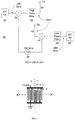
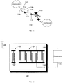
- An IDT 10 is a series of thin metal strips or "fingers” 12 fabricated on a suitable piezoelectric substrate 14. One set of fingers is connected to an input/output terminal 16, while the opposite set of fingers is connected to another terminal 18. In single-ended IDTs, terminal 18 is grounded. For differential input signals however, terminal 18 is a pulse input/output terminal. Spacing "W" between IDT segments is adjusted to conform to the desired chip period of the coded sequence. When excited by a narrow pulse at terminal 16, the IDT generates a coded output SAW which propagates in both directions perpendicular to the fingers 12.
- Fig. 1 can operate as both a SAW expander, generating a SAW output from a single pulse input, and a SAW compressor, generating a single pulse or peak output from a SAW input.
- Terminal 16 is both a pulse input terminal and a pulse output terminal.
- Conversion of an output SAW into an electrical signal for further processing in conventional communications circuits and subsequent transmission through an antenna is accomplished by adding a transmit IDT 24, aligned with the IDT 22, as shown in Fig. 2. Both IDTs can be fabricated on the same substrate 14.
- a SAW output from IDT 22 is converted into an electrical signal by TX IDT 24.
- a SAW receiver would have the same structure as in Fig. 2.
- a signal input to a receive IDT from receiver processing circuitry would be converted to a SAW which is input to IDT 22.
- the TX IDT 24 may be a differential IDT, wherein the grounded lower terminal would be a pulse output terminal.
- Tf is the width of a metallized finger 12 and Ts is the width of the space between the fingers 12.
- Tf and Ts are equal to a quarter of a wavelength, ⁇ /4. Since wavelength is inversely proportional to frequency of operation, higher frequency IDTs require thinner fingers 12 located in close proximity to each other, which complicates fabrication and reduces fabrication yields.
- ⁇ /4 dimension could be in the order of 0.425 microns, depending upon the substrate chosen.
- the mixers 34 and 44, oscillator 36 and filters 38 and 46 from the communications system 30, result in additional cost, power consumption, occupation in space and a much complex system than is desired for low-cost, low power, short range communication systems. Therefore, there remains a need in the art to reduce the number of components in such a communication system.
- BluetoothTM wireless technology is one such prior art example.
- Bluetooth is a de facto standard, as well as a specification for small-form factor, low-cost, short range radio links between mobile PCs, mobile phones and other portable wireless devices.
- the current Bluetooth short range communications specification operates in the 2.4 GHz (ISM) band; however, in reality the technology for mobile communication devices involves undesirable high cost, substantial power consumption and relatively complex hardware.
- SAW devices utilized by the present invention for filtering at near-ISM band frequencies may cost approximately $1.00 each.
- a comparable semiconductor Bluetooth solution may cost greater than $10.00.
- the manufacturing required for the present invention allows for SAW fabrication that utilizes simple, single layer photolithographic techniques.
- Another object of the invention is to provide a low power SAW solution for short range communications.
- the SAW uses passive thin film technology and requires only a pulse to excite and produce an RF waveform. Likewise it can perform an autocorrelation function passively. This compares to prior SAW techniques which require frequency conversion circuitry such as mixers, filters and oscillators, and the complex Bluetooth techniques that require separate receive, transmit and processing circuitry. In mobile communication environments, power consumption and size are of primary importance.
- a still further object of the invention is to provide a SAW-based communication arrangement which occupies minimal space.
- a complete SAW package in accordance with the invention is in the order of 3mm x 3mm.
- the inventive SAW system reduces manufacturing complexity and cost and increases production yields by exploiting second harmonic components produced by expander/compressor IDTs. This allows the IDTs to be fabricated with larger finger widths than would be required according to known IDT methods and devices.
- a wireless communication system comprises an expander/compressor interdigital transducer (IDT) which produces a surface acoustic wave (SAW) output comprising frequency components at a fundamental frequency and a plurality of harmonic frequencies when excited with an electric input signal and produces an electric output signal when excited by a SAW input at the fundamental frequency or one or more of the plurality of harmonic frequencies, a transmit IDT positioned adjacent to the expander/compressor IDT and switchably connected to an antenna, and a receive IDT positioned adjacent to the expander/compressor IDT and switchably connected to the antenna, wherein the transmit IDT and the receive IDT are configured to operate at one of the harmonic frequencies.
- IDT expander/compressor interdigital transducer
- SAW surface acoustic wave
- a communication system comprises an expander IDT configured to produce a SAW output having a fundamental frequency and a plurality of harmonic frequencies when excited with an electric input signal, a transmit IDT positioned adjacent to the expander IDT and connected to an antenna, a receive IDT connected to the antenna; and a compressor IDT positioned adjacent to the receive IDT and configured to produce an electric output signal when excited by a SAW input comprising the fundamental frequency or one or more the plurality of harmonic frequencies, wherein the transmit IDT and the receive IDT are configured to operate at one of the harmonic frequencies.
- the transmit IDT converts a SAW into an electric signal for transmission via the antenna and the receive IDT converts an electric signal received via the antenna into a SAW.
- the fundamental frequency may be 1.2 GHz and the transmit IDT and receive IDT operate at the second harmonic frequency of 2.4 GHz.
- Wireless communication systems according to the invention may be installed in both a wireless mobile communication device and a wireless earpiece detachable therefrom, to provide for communication between the mobile device and the earpiece.
- a SAW-based wireless communication system is installed in a wireless mobile communication device, a wireless earpiece detachable therefrom and a holder for the mobile device connected to a personal computer (PC), to provide for communication between the device and the PC through the holder, the device and the earpiece, and the earpiece and the PC through the holder.
- PC personal computer
- the electric input and output signals associated with any of the IDTs may be either unbalanced or differential signals.
- An expander/compressor IDT, or an expander IDT and a compressor IDT are preferably configured to embody a code and thereby produce a coded SAW output when excited with an input electric pulse and an output electric pulse when excited by a coded SAW input.
- the code embodied by these IDTs may be a Barker code such as a 5-bit Barker code, and may be used for example to represent identification information for an article with which the wireless communication system is associated.
- a passive wireless communication system comprises an antenna for receiving communication signals and converting the received communication signals into electric antenna output signals and converting electric antenna input signals into output communication signals and transmitting the output communication signals, a first IDT connected to the antenna and configured to produce first SAW outputs in response to the electric antenna output signals and to produce the antenna input signals in response to first SAW inputs, a second IDT positioned adjacent to the first IDT and configured to produce a second SAW output comprising frequency components at a fundamental frequency and a plurality of harmonic frequencies when excited with an electric signal and to produce an electric signal output when excited by a second SAW input at the fundamental frequency or one or more of the plurality of harmonic frequencies, and a termination circuit connected to the second IDT, wherein the first IDT is configured to operate at one of the harmonic frequencies, the termination circuit causes the second IDT to reflect a second SAW output toward the first IDT in response to each first SAW output produced by the first IDT, and the first IDT produces an antenna input signal in response to each reflected
- a passive wireless communication system further comprises a third IDT which is positioned between the first IDT and the second IDT and reflects a third SAW output toward the first IDT in response to the first SAW output produced by the first IDT, wherein the first IDT produces a second antenna input signal in response to the reflected second SAW output from the third IDT.
- the passive wireless communication system may also include a fourth IDT which is positioned adjacent to the second IDT on a side of the second IDT opposite to the third IDT and reflects a third SAW output toward the first IDT in response to the first SAW output produced by the first IDT, wherein the first IDT produces a third antenna input signal in response to the reflected third SAW output from the fourth IDT.
- these IDTs are preferably configured to operate at one of the harmonic frequencies, which may be the same as the harmonic frequency at which the first IDT operates.
- the third and fourth IDTs may be connected to a respective termination circuit.
- a termination circuit is preferably either an open circuit, a short circuit or a sensor circuit.
- the passive wireless system preferably receives communication signals from a remote interrogation system, and through operation of the IDTs and termination circuit, automatically and passively responds to the remote interrogation system.
- An IDT which may be used in embodiments of the invention preferably comprises a pair of substantially parallel electrically conductive rails and one or more groups of interdigital elements, each group comprising a plurality of interdigital elements. Each interdigital element is connected to one of the rails and extends substantially perpendicular thereto toward the other rail. Any such IDT may be configured to embody a particular code as determined by a connection pattern of the interdigital elements in each group.
- a coded IDT performs a passive autocorrelation function on a SAW input based on the code to thereby produce an electric pulse output when the SAW input is similarly coded.
- a SAW system may be employed in the design of virtually any new short range wireless communication system, for example to enable communication between an earpiece unit and an associated mobile communications device, as described briefly above and in further detail below.
- the inventive systems may also replace RF signal generation circuitry in existing short range communications system, including for example "Bluetooth” systems.
- a further system in accordance with the invention may be employed in "smart" identification tag systems and remote interrogation systems such as inventory systems and meter reading/telemetry systems.
- the lithographic process to produce SAW devices at higher frequencies is difficult due to the very small finger width.
- the wavelength would be approximately 1.7 microns, requiring a finger width of 0.425 microns depending on the substrate chosen. This very small width will affect the overall yield of the fabrication process and will impact on the price of the devices.
- a solution to this problem would be to fabricate the device to operate at 1.2 GHz to produce a wavelength of 3.4 microns using unique finger geometry and then take advantage of the second harmonic that the device will support. This will allow for a more relaxed lithographic process and increase production yield, as the lines are not as thin and are spaced farther from each other.
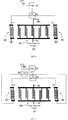
- FIG. 5 illustrates an example of the finger configuration for a second harmonic SAW device with 2 chips (+ and -).
- the substrate 14 has been omitted for clarity, but it is to be understood that IDT structures may be fabricated on a common substrate.
- a so-called "three-finger" IDT in which each of the four groups of fingers includes three fingers, is required for second harmonic operation. Corresponding fingers of each group are separated by a distance 'a' equal to fundamental wavelength ⁇ 0 . Each finger and space in this three-finger IDT therefore has a width 'b' of ⁇ 0 /6.
- the finger and space width of the second harmonic IDT is ⁇ 0 /6.
- Fig. 5 shows a single-ended IDT with a grounded lower terminal, but a differential IDT design could also be employed.
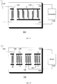
- a SAW-based communications system could comprise an expander/compressor IDT 52, a transmit (TX) IDT 56 and a receive (RX) IDT 60. These structures are in-line with each other as shown in Fig. 6. As discussed above in relation to Fig. 2, these structures may be placed on a suitable piezoelectric substrate using thin film lithographic procedures.
- a narrow pulse which represents digital data and can be generated by using simple digital circuitry or an existing data source is injected into the middle IDT 52 of Fig. 6 through pulse input and output terminal 54 to activate a piezoelectric effect that converts electrical to mechanical (acoustic wave) motion.
- the acoustic waves can be coded depending on the geometry of the IDT 52. These acoustic waves then propagate within the substrate to the TX IDT 56. The coded acoustic waves are then transformed to an electrical coded RF signal within the proximity of the TX IDT 56.
- the TX IDT 56 is attached to a suitable antenna 58 through the switch 62 and band pass filter 57, the coded RF signal can propagate throughout the air.
- a coded electrical signal that enters the RX IDT 60 via the antenna 58, band pass filter 57 and switch 62 generates an acoustic wave that propagates towards the middle expander/compressor IDT 52.
- An autocorrelation function is passively performed in the IDT 52 and if the coded waveform from the RX IDT 60 matches with the code on the expander/compressor IDT 52, a peak is generated at the pulse input and output terminal 54.
- any of the IDTs shown in Fig. 6 could be implemented as differential IDTs.
- a fully differential system is shown in Fig. 7.
- all of the grounded terminals in Fig. 7 are pulse input and output terminals in Fig. 7.
- two switches 58 and 58' are shown, a single differential switching arrangement may be used.
- the filter 61' and antenna 62' must also be differential components.
- Expander/compressor IDT 52' may be single-ended, with terminal 55' grounded as shown in Fig. 6, or differential, wherein terminal 55' is a pulse input and output terminal.
- the differential system in Fig. 7 operates similarly to the system of Fig. 6, as will be apparent to those skilled in the art.
- the peak produced by an expander/compressor IDT such as 52 or 52' can represent digital data.
- an on-off keying technique following an intialization or synchronization sequence, the presence of a peak within a bit period may be interpreted as a '1' data bit, whereas the absence of a peak would represent a '0' bit.
- the coding of the expander/compressor IDTs 52, 52' and the associated autocorrelation function performed by the IDTs as discussed above are determined by the finger geometry of the IDT.
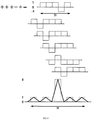
- a preferred IDT coding scheme is a Barker code. Barker codes are particularly useful for IDT coding, since they minimize the energy in the side lobes associated with a compressed pulse generated by the autocorrelation function performed on a SAW input to an expander/compressor IDT.
- the expander/compressor IDT 52 embodies a 5 bit + + + - + Barker code.
- Fig. 8 shows an example of the autocorrelation function performed by the expander/compressor IDT 52 of Fig. 6 when a signal received through the antenna 58 and switch 62 is converted to a SAW by RX IDT 60.
- the autocorrelation function is mathematically equivalent to a series of shift and add operations as shown in Fig. 8 and generates the peak and associated side lobes shown at the bottom of Fig. 8.
- the amplitude of the autocorrelation peak is proportional to the code length N, which is 5 in the example shown in Fig. 8, whereas the side lobes are amplitude 1.
- This passive autocorrelation decodes received signals that were generated with an identically-coded IDT.
- FIGs. 6 and 7 Also evident from Figs. 6 and 7 are the relative lengths of the RX IDTs 60, 60', the expander/compressor IDTs 52, 52' and TX IDTs 56, 56'.
- expander/compressor IDTs 52, 52' are fabricated with a finger width of 0.567 microns to facilitate second harmonic operation at 2.4 GHz. Only the shorter IDTs 56, 56', 60 and 60' must be fabricated for 2.4 GHz operation with the smaller finger width of 0.425 microns. Therefore, the more stringent manufacturing requirements apply only to the shorter elements, which will increase production yields.
- the antenna switch 62 in Fig. 6 and switches 62 and 62' in Fig. 7 are required to prevent feedback of a transmission signal from the TX IDTs 56 and 56' to the RX IDTs 60, 60', which would occur if both the TX and RX IDTs were connected to the antennas 58, 58'. Such feedback would cause the RX IDTs 60, 60' to convert the fed back signal to a SAW, which in turn would propagate through IDT 52, 52' and cause interference.
- Switches 62, 62' similarly prevent a received signal from feeding back through the TX IDT 56, 56'.
- small-scale switches of the type normally employed in such arrangements tend to be prone to failure.
- the switch and associated complex control circuits also occupy space and consume power. Such problems are critical concerns in highly integrated device designs and mobile communications equipment in which SAW systems according to the instant invention could be employed.
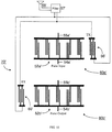
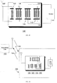
- the SAW-based communication system 70 has an expander IDT 52a and a compressor IDT 52b.
- a pulse representing data input at terminal 54 is converted to a coded SAW by expander IDT 52a.
- Transmit IDT 56 then converts the resultant coded SAW into an electrical signal for transmission via band pass filter 57 and antenna 58.
- Feedback of the transmit signal to the RX IDT 60 does not interfere with the IDT 52a in the transmit module 80a.
- Pulse output 54b is not read during signal transmission to prevent erroneous data detection.
- a signal received at antenna 58 is filtered by band pass filter 57, input to RX IDT 60, converted to a SAW and decoded by autocorrelation in compressor IDT 52b provided the received signal code corresponds to the coding of IDT 52b.
- the autocorrelation peak is output at terminal 54b.
- the received signal is split between the TX IDT 56 and the RX IDT 60, the SAW generated at TX IDT 56 causes no interference with the receive module 80b. Any pulse output on terminal 54a during a receive operation is ignored.
- the IDTs shown in Fig. 9 are similar in construction to those in Fig. 6.
- the expander IDT 52a and compressor IDT 52b are fabricated for second harmonic operation at 2.4 GHz and coded in the same way as IDT 52 of Fig. 6.
- TX IDT 56 and RX IDT 60 operate at a fundamental frequency of 2.4 GHz.
- any of the IDTs in Fig. 9 may be differential IDTs, as shown in Fig. 10.
- terminals of the TX IDT 56 and RX IDT 60 shown as grounded in Fig. 9 are pulse input or output terminals in Fig. 10.
- single-ended IDTs are preferred for the expander IDT 52a' and compressor IDT 52b', these IDTs may also be differential IDTs, in which case terminals 55a' and 55b' are connected as pulse input and output terminals, respectively, instead of to ground.
- This SAW based technology will allow communication devices to be placed in power sensitive applications such as a wireless earpiece to allow the user a longer "talk-time" over Bluetooth devices.
- This invention may be incorporated into any situation for which Bluetooth was designed.
- An illustrative example of a system into which a system in accordance with the first or second embodiment could be incorporated is shown in Fig. 11.
- 102 denotes an earpiece
- 104 is a mobile wireless communication device
- 106 is a holder or cradle for holding the device 104 and coupling device 104 to a personal computer (PC) 110.
- the earpiece 102, device 104 and cradle 106 incorporate a SAW communication device as disclosed above. This allows a user to communicate audibly between the wireless communication device 104, which may for example be carried on their belt or person, and the wireless earpiece 102 with a built-in microphone, as indicated at 108a in Fig. 11.
- This system could be then expanded to include communication between the earpiece 102 and the personal computer 110, as indicated by 108b, when a SAW system in cradle 106 is attached to the PC via a bus connection.
- This system may then be further expanded to include network communications (designated 108c in Fig. 11) between the wireless device 104 on the belt or person with the PC 110 to incorporate connectivity via small pico-cell networks.
- a further extension of the communication systems according to the first and second embodiments could be a personal area network (PAN) based on SAW technology rather than the more excessive Bluetooth strategy.
- PAN personal area network
- the second harmonic design techniques discussed above are applied to passive SAW RF systems.
- SAW devices usually perform only as RF expanders.
- a passive system 120 may comprise two IDTs 122 and 124.
- IDT 124 is fabricated according to fundamental frequency criteria, whereas IDT 122 operates at a harmonic of the fundamental, as discussed above.
- a pulse that has been sent out by a local requesting unit is received at the antenna 128 and excites IDT 122 to produce an acoustic wave.
- This wave then propagates to a coded IDT 124 that has a suitable termination 126 connected across its terminals 132 and 134 to produce a reflection coefficient of magnitude 1.
- Termination 126 could be an open or short circuit termination, which will re-excite the coded IDT 124 to produce a coded acoustic wave back to the IDT 122 that is connected to the antenna 128. The result is that an impulse sent out by a local requesting unit excites a coded IDT which then returns back to the requesting unit a coded RF waveform.
- autocorrelation of the coded waveform returned from the device 120 would preferably be performed by a DSP or other conventional signal processing circuitry, such that different codes can be used for different IDTs such as IDT 124.
- a separate coded IDT must be provided in the requesting unit for each different code embodied in all devices 120 with which communication is desired. This would severely limit the number of devices 120 that could be deployed.
- the size of the complete SAW device 120 could be on the order of 3mm square. This would allow the device to be incorporated into labels such as shipping or address labels, equipment name plates, adhesive stickers such as vehicle license plate stickers and other forms of identification tags.
- the code embodied in the IDT 124 could for example be a code that provides information about an item to which the device 120 is attached. Device 120 could therefore be implemented in an identification or location system for example.
- IDT 122 in Fig. 12 is a single-ended IDT, a differential design is also contemplated, as shown in Fig. 13.
- IDT 124 is shown as a coded IDT that produces a coded reflected SAW that can provide information to the requesting unit. However, in the systems of Figs. 14 and 15, the IDTs are not coded. As shown in Fig. 14 for example, the passive communication system includes four IDTs, 122, 136, 138 and 142, of which IDTs 136, 138 and 142 are fabricated as fundamental frequency components. IDT 122 is fabricated for operation at a harmonic frequency of fundamental. The terminals of IDT 136 are either open circuited as in Fig.
- IDT 142 short circuited such that a SAW produced by IDT 122 in response to a pulse received from a requesting unit by antenna 128 is reflected back toward the IDT 122 by IDT 136.
- a return RF signal is therefore transmitted to the requesting unit as discussed above in relation to Fig. 12, although the return signal generated by device 130 is not coded.
- the terminals of IDT 142 are also either open or shorted, to thereby generate a second return signal to the requesting unit.
- the middle IDT 138 is connected to a sensor 144, which may for example be a load impedance which changes according to a sensed characteristic or property such as moisture or temperature.
- a further reflected SAW is generated by IDT 138 and results in a third RF return signal.
- the reflection characteristics and thus the magnitude and phase of the RF return signal generated by the so-called reference IDTs 136 and 142 are known, depending upon the open or short circuiting of the terminals. These reference return signals can be compared to the return signal generated by the IDT 138 to determine the state of sensor 144 and thereby the value of the measured characteristic or property.
- the device 130' shown in Fig. 15 is a fully differential realization of the device 130.
- FIG. 16 shows a system into which passive SAW RF devices according to the third embodiment of the invention could be implemented.
- a requesting unit 150 which may for example be a hand-held unit with a display or part of a larger interrogation and tracking system, sends an RF pulse 152 to a label, tag or the like generally indicated at 160.
- the tag 160 includes a SAW device 120, 120', 130 or 130' and may be attached to or placed on or inside an item or at a location where measurement by sensor 144 is to be made.
- the return signals 154 generated by the SAW device in tag 160 are received at the requesting device. For a device 120 or 120', which produces a coded return signal 154, the return signal is processed to determine tag information.
- the signals are compared to determine sensor information.
- the tag or sensor information thus determined may for example be displayed to a user or operator of the requesting device 150, forwarded from the requesting unit 150 to an information, tracking or billing system for further processing, or both.
Landscapes
- Physics & Mathematics (AREA)
- Acoustics & Sound (AREA)
- Engineering & Computer Science (AREA)
- Radar, Positioning & Navigation (AREA)
- Remote Sensing (AREA)
- Computer Networks & Wireless Communication (AREA)
- General Physics & Mathematics (AREA)
- Surface Acoustic Wave Elements And Circuit Networks Thereof (AREA)
- Transmitters (AREA)
Abstract
Description
- Fig. 1
- shows an IDT;
- Fig. 2
- is a block diagram of a conventional SAW-based transmit IDT;
- Fig. 3
- is an illustration of typical finger geometry in an IDT;
- Fig. 4
- is a block diagram of a prior art SAW-based communication system;
- Fig. 5
- is an IDT adapted for second harmonic operation;
- Fig. 6
- shows a representation of a first embodiment of the invention;
- Fig. 7
- is a differential implementation of the first embodiment;
- Fig. 8
- illustrates an autocorrelation function of a 5 bit Barker code;
- Fig. 9
- is a second embodiment of the invention;
- Fig. 10
- is a differential implementation of the second embodiment;
- Fig. 11
- represents a system in which the invention could be implemented;
- Fig. 12
- illustrates a third embodiment of the invention;
- Fig. 13
- is a differential implementation of the third embodiment;
- Fig. 14
- shows a variation of the third embodiment;
- Fig. 15
- is a differential implementation of the system of Fig. 14; and
- Fig. 16
- is a block diagram of a system in which the third embodiment could be employed.
Claims (38)
- A wireless communication system comprising:wherein the transmit IDT and the receive IDT are configured to operate at one of the harmonic frequencies.a. an expander/compressor interdigital transducer (IDT) which produces a surface acoustic wave (SAW) output comprising frequency components at a fundamental frequency and a plurality of harmonic frequencies when excited with an electric input signal and produces an electric output signal when excited by a SAW input at the fundamental frequency or one or more of the plurality of harmonic frequencies;b. a transmit IDT positioned adjacent to the expander/compressor IDT and switchably connected to an antenna; andc. a receive IDT positioned adjacent to the expander/compressor IDT and switchably connected to the antenna,
- The wireless communication system of claim 1, wherein the transmit IDT receives the SAW output from the expander/compressor IDT and produces an electric output signal for transmission via the antenna and the receive IDT produces the SAW input to the expander/compressor IDT from an electric signal received via the antenna.
- The wireless communication system of claim 1, wherein the fundamental frequency is 1.2 GHz and the transmit IDT and receive IDT operate at the second harmonic frequency of 2.4 GHz.
- The wireless communication system of claim 1, installed in both a wireless mobile communication device and a wireless earpiece detachable therefrom, to provide for communication between the mobile device and the earpiece.
- The wireless communication system of claim 1, installed in a wireless mobile communication device, a wireless earpiece detachable therefrom and a holder for the mobile device connected to a personal computer (PC), to provide for communication between the device and the PC through the holder, the device and the earpiece, and the earpiece and the PC through the holder.
- The wireless communication system of claim 1, wherein the transmit IDT has a differential electric signal output and the receive IDT has a differential electric signal input.
- The wireless communication system of claim 1, wherein the expander/compressor IDT has differential electric signal input/output terminals.
- The wireless communication system of claim 1, wherein the expander/compressor IDT is configured to embody a code and thereby produces a coded SAW output when excited with an input electric pulse and produces an output electric pulse when excited by a coded SAW input.
- The wireless communication system of claim 8, wherein the expander/compressor IDT performs a passive autocorrelation function on the coded SAW input based on the code to thereby produce the electric pulse output.
- The wireless communication system of claim 8, wherein the code is a Barker code.
- The wireless communication system of claim 9, wherein the Barker code is a 5-bit Barker code.
- The wireless communication system of claim 9, wherein the Barker code is a 13-bit Barker code.
- The wireless communication system of claim 8, wherein the expander/compressor IDT comprises:a. a pair of substantially parallel electrically conductive rails; andb. one or more groups of interdigital elements, each group comprising a plurality of interdigital elements and each interdigital element being connected to one of the rails and extending substantially perpendicular thereto toward the other rail,
wherein a connection pattern of the interdigital elements to the rails defines the code. - A wireless communication system comprising:wherein the transmit IDT and the receive IDT are configured to operate at one of the harmonic frequencies.a. an expander interdigital transducer (IDT) configured to produce a surface acoustic wave (SAW) output having a fundamental frequency and a plurality of harmonic frequencies when excited with an electric input signal;b. a transmit IDT positioned adjacent to the expander IDT and connected to an antenna;c. a receive IDT connected to the antenna; andd. a compressor IDT positioned adjacent to the receive IDT and configured to produce an electric output signal when excited by a SAW input comprising the fundamental frequency or one or more the plurality of harmonic frequencies,
- The wireless communication system of claim 14, wherein the transmit IDT and receive IDT operate at the second harmonic of the fundamental frequency.
- The wireless communication system of claim 14, installed in both a wireless mobile communication device and a wireless earpiece detachable therefrom, to provide for communication between the mobile device and the earpiece.
- The wireless communication system of claim 14, installed in a wireless mobile communication device, a wireless earpiece detachable therefrom and a holder for the mobile device connected to a personal computer (PC), to provide for communication between the device and the PC through the holder, the device and the earpiece, and the earpiece and the PC through the holder.
- The wireless communication system of claim 14, wherein the expander IDT has differential electric signal input terminals, the transmit IDT has a differential electric signal output, the receive IDT has a differential electric signal input, and the compressor IDT has differential electric signal output terminals.
- The wireless communication system of claim 14, wherein the expander IDT and the compressor IDT each comprise:a. a pair of substantially parallel electrically conductive rails; andb. one or more groups of interdigital elements, each group comprising a plurality of interdigital elements.
- The wireless communication system of claim 19, wherein each interdigital element is connected to one of the rails and extends substantially perpendicular thereto toward the other rail.
- The wireless communication system of claim 20, wherein a connection pattern of the interdigital elements in each group defines a code.
- The wireless communication system of claim 21, wherein the code is a Barker code.
- The wireless communication system of claim 14, wherein the SAW output from the expander IDT is converted into an electric signal for transmission via the antenna by the transmit IDT.
- The wireless communication system of claim 14, wherein the receive IDT converts an electric signal received via the antenna into a SAW input to the compressor IDT.
- A passive wireless communication system comprising:whereina. an antenna fori. receiving communication signals and converting the received communication signals into electric antenna output signals, andii. converting electric antenna input signals into output communication signals and transmitting the output communication signals;b. a first interdigital transducer (IDT) connected to the antenna and configured to produce first surface acoustic wave (SAW) outputs in response to the electric antenna output signals and to produce the antenna input signals in response to first SAW inputs;c. a second IDT positioned adjacent to the first IDT and configured to produce a second SAW output comprising frequency components at a fundamental frequency and a plurality of harmonic frequencies when excited with an electric signal and to produce an electric signal output when excited by a second SAW input at the fundamental frequency or one or more of the plurality of harmonic frequencies; andd. a termination circuit connected to the second IDT,the first IDT is configured to operate at one of the harmonic frequencies;the termination circuit causes the second IDT to reflect a second SAW output toward the first IDT in response to each first SAW output produced by the first IDT; andthe first IDT produces an antenna input signal in response to each reflected second SAW output from the second IDT.
- The passive wireless communication system of claim 25, further comprising a third IDT which is positioned between the first IDT and the second IDT and reflects a third SAW output toward the first IDT in response to the first SAW output produced by the first IDT, wherein the first IDT produces a second antenna input signal in response to the reflected second SAW output from the third IDT.
- The passive wireless communication system of claim 26, further comprising a fourth IDT which is positioned adjacent to the second IDT on a side of the second IDT opposite to the third IDT and reflects a third SAW output toward the first IDT in response to the first SAW output produced by the first IDT, wherein the first IDT produces a third antenna input signal in response to the reflected third SAW output from the fourth IDT.
- The passive wireless communication system of claim 25, wherein the second IDT comprises:wherein a connection pattern of the interdigital elements to the rails defines a code.a. a pair of substantially parallel electrically conductive rails; andb. one or more groups of interdigital elements, each group comprising a plurality of interdigital elements and each interdigital element being connected to one of the rails and extending substantially perpendicular thereto toward the other rail,
- The passive wireless communication system of claim 27, wherein the third IDT and the fourth IDT are configured to operate at one of the harmonic frequencies.
- The passive wireless communication system of claim 29, wherein the first IDT, the third IDT and the fourth IDT are configured to operate at the same harmonic frequency.
- The passive wireless communication system of claim 25, wherein the termination circuit is a short circuit.
- The passive wireless communication system of claim 25, wherein the termination circuit is an open circuit.
- The passive wireless communication system of claim 25, wherein the termination circuit is a sensor circuit.
- The passive wireless communication system of claim 27, further comprising a second termination circuit connected to the third IDT and a third termination circuit connected to the fourth IDT.
- The passive wireless communication system of claim 34, wherein the second termination circuit is an open circuit or a short circuit.
- The passive wireless communication system of claim 34, wherein the third termination circuit is an open circuit or a short circuit.
- The passive wireless communication system of claim 25, wherein the received communication signals are interrogation signals transmitted from a remote interrogation system.
- The passive wireless communication system of claim 37, wherein the antenna converts the antenna input signal produced by the first IDT into a communication signal for transmission to the remote interrogation system.
Applications Claiming Priority (2)
| Application Number | Priority Date | Filing Date | Title |
|---|---|---|---|
| US20915200P | 2000-06-02 | 2000-06-02 | |
| US209152 | 2000-06-02 |
Publications (3)
| Publication Number | Publication Date |
|---|---|
| EP1160975A2 true EP1160975A2 (en) | 2001-12-05 |
| EP1160975A3 EP1160975A3 (en) | 2002-02-20 |
| EP1160975B1 EP1160975B1 (en) | 2008-05-14 |
Family
ID=22777562
Family Applications (1)
| Application Number | Title | Priority Date | Filing Date |
|---|---|---|---|
| EP01113311A Expired - Lifetime EP1160975B1 (en) | 2000-06-02 | 2001-05-31 | A wireless communication system using surface acoustic wave (SAW) second harmonic techniques |
Country Status (5)
| Country | Link |
|---|---|
| US (6) | US6825794B2 (en) |
| EP (1) | EP1160975B1 (en) |
| AT (1) | ATE395747T1 (en) |
| CA (1) | CA2348723C (en) |
| DE (1) | DE60133968D1 (en) |
Cited By (4)
| Publication number | Priority date | Publication date | Assignee | Title |
|---|---|---|---|---|
| EP2025011A1 (en) * | 2006-03-13 | 2009-02-18 | Xg Technology, Inc. | Carrier less modulator using saw filters |
| FR3030154A1 (en) * | 2014-12-10 | 2016-06-17 | Sasu Frec'n'sys | ELASTIC SURFACE WAVE SENSOR DEVICE WITH STABLE ELECTRICAL RESPONSE |
| CN111256280A (en) * | 2018-11-30 | 2020-06-09 | 广东美的制冷设备有限公司 | Operation control method and system, compressor and air conditioner |
| CN112986398A (en) * | 2021-03-15 | 2021-06-18 | 南昌航空大学 | Electromagnetic ultrasonic Lamb wave transducer and online detection system and method |
Families Citing this family (26)
| Publication number | Priority date | Publication date | Assignee | Title |
|---|---|---|---|---|
| US6825794B2 (en) * | 2000-06-02 | 2004-11-30 | Research In Motion Limited | Wireless communication system using surface acoustic wave (SAW) second harmonic techniques |
| EP1684477B1 (en) | 2001-06-18 | 2008-12-03 | Research In Motion Limited | System and method for managing message attachments |
| US7005964B2 (en) * | 2002-04-08 | 2006-02-28 | P. J. Edmonson Ltd. | Dual track surface acoustic wave RFID/sensor |
| US7158763B2 (en) * | 2003-05-02 | 2007-01-02 | P. J. Edmonson Ltd. | Multi-IDT SAW hybrid communication system |
| US7653118B1 (en) * | 2004-03-26 | 2010-01-26 | Cypress Semiconductor Corporation | Chirped surface acoustic wave (SAW) correlator/expander |
| EP1730472A1 (en) * | 2004-04-02 | 2006-12-13 | Kistler Holding AG | Sensor comprising a surface wave component |
| EP1753164A4 (en) * | 2004-06-04 | 2015-04-29 | Panasonic Ip Man Co Ltd | Radio communication device |
| US7140261B2 (en) * | 2005-04-27 | 2006-11-28 | Honeywell International Inc. | Acoustic wave flow sensor |
| US7243544B2 (en) | 2005-06-16 | 2007-07-17 | Honeywell International Inc. | Passive and wireless acoustic wave accelerometer |
| GB0515523D0 (en) * | 2005-07-28 | 2005-12-07 | Bae Systems Plc | Transponder |
| US20070079656A1 (en) * | 2005-10-11 | 2007-04-12 | Honeywell International Inc. | Micro-machined acoustic wave accelerometer |
| KR100810353B1 (en) * | 2006-01-10 | 2008-03-04 | 삼성전자주식회사 | Mobile phone with game and user's interfacing device thereof |
| US8608088B2 (en) * | 2007-12-05 | 2013-12-17 | Wavelogics Ab | Data carrier device |
| US8044797B2 (en) * | 2009-01-27 | 2011-10-25 | Bae Systems Information And Electronic Systems Integration Inc. | System for locating items |
| DE102010006334A1 (en) * | 2010-01-29 | 2011-08-04 | pro-micron GmbH & Co. KG, 87600 | System and method for interference suppression in frequency modulated radar systems |
| US9097789B2 (en) * | 2012-03-13 | 2015-08-04 | Duke Loi | Apparatus and method for electromagnetic wave structure modulation |
| CN103199734B (en) * | 2013-05-08 | 2015-08-05 | 苏州科技学院 | A kind of single-electrical signal drives two-way rotary ultrasonic motor |
| US9404810B2 (en) * | 2014-04-16 | 2016-08-02 | Mnemonics, Inc. | Wireless surface acoustic wave temperature sensor and interrogation system apparatus capable of generating a self synchronizing shaft position indicator for moving platforms |
| JP6347446B2 (en) * | 2014-12-11 | 2018-06-27 | 太陽誘電株式会社 | Horizontally coupled multimode monolithic filter |
| JP6307021B2 (en) * | 2014-12-19 | 2018-04-04 | 太陽誘電株式会社 | Elastic wave device |
| US10355668B2 (en) * | 2015-01-20 | 2019-07-16 | Taiyo Yuden Co., Ltd. | Acoustic wave device |
| WO2017151506A1 (en) * | 2016-02-29 | 2017-09-08 | Capital One Services, Llc | Batteryless payment device with wirelessly powered token provisioning |
| KR102417610B1 (en) | 2016-03-03 | 2022-07-07 | 삼성전자주식회사 | Method and apparatus for reading code using short range mmwave radar |
| CN107464990B (en) * | 2016-06-06 | 2019-11-05 | 仁宝电脑工业股份有限公司 | Tunable antenna device |
| CN107769752A (en) * | 2017-11-17 | 2018-03-06 | 中电科技集团重庆声光电有限公司 | A kind of multiple channel acousto surface filtering module |
| IT202000001030A1 (en) * | 2020-01-21 | 2021-07-21 | Inxpect S P A | Radar system and its diagnostic method |
Citations (1)
| Publication number | Priority date | Publication date | Assignee | Title |
|---|---|---|---|---|
| EP0797315A2 (en) * | 1996-03-22 | 1997-09-24 | Kazuo Tsubouchi | Code division multiple access apparatus |
Family Cites Families (51)
| Publication number | Priority date | Publication date | Assignee | Title |
|---|---|---|---|---|
| US2745067A (en) | 1951-06-28 | 1956-05-08 | True Virgil | Automatic impedance matching apparatus |
| US2742618A (en) | 1951-12-29 | 1956-04-17 | Collins Radio Co | Phasing and magnitude adjusting circuit |
| US3681579A (en) * | 1970-10-20 | 1972-08-01 | Hughes Aircraft Co | Non-interacting complementary coding system |
| FR2298903A1 (en) | 1975-01-22 | 1976-08-20 | Thomson Csf | ANTENNA ADAPTATION DEVICE AND ANTENNA EQUIPPED WITH SUCH A DEVICE |
| US4137497A (en) * | 1977-10-31 | 1979-01-30 | Raythoon Company | Frequency measuring apparatus |
| US4210900A (en) * | 1978-08-16 | 1980-07-01 | Honeywell Inc. | Surface acoustic wave code reader |
| US4206380A (en) * | 1978-12-22 | 1980-06-03 | Hitachi, Ltd. | Piezoelectric surface acoustic wave device with suppression of reflected signals |
| US4247903A (en) | 1979-01-08 | 1981-01-27 | United Technologies Corporation | Monolithic isolated gate FET saw signal processor |
| US4249146A (en) * | 1979-02-23 | 1981-02-03 | Trw Inc. | Surface acoustic wave resonators utilizing harmonic frequencies |
| DE3033407A1 (en) | 1980-09-05 | 1982-04-22 | Robert Bosch Gmbh, 7000 Stuttgart | Two-way radio |
| DE3267639D1 (en) * | 1981-02-04 | 1986-01-09 | Matsushita Electric Ind Co Ltd | Surface acoustic wave device |
| US4405974A (en) * | 1981-02-06 | 1983-09-20 | Harvey Hubbell Incorporated | Filter assembly for luminaire |
| US4405874A (en) * | 1982-03-01 | 1983-09-20 | Northern Telecom Limited | Surface acoustic wave (saw) devices having series-connected inter-digital transducers |
| US4612669A (en) | 1985-04-30 | 1986-09-16 | Rca Corporation | Antenna matching system |
| US4737790A (en) * | 1986-03-03 | 1988-04-12 | X-Cyte, Inc. | Passive interrogator label system with a surface acoustic wave transponder operating at its third harmonic and having increased bandwidth |
| US4746830A (en) | 1986-03-14 | 1988-05-24 | Holland William R | Electronic surveillance and identification |
| US5170500A (en) | 1990-08-03 | 1992-12-08 | Goldstar Products Co., Limited | Intermediate frequency circuit for cellular telephone transceiver using surface acoustic wave filter |
| US5187454A (en) | 1992-01-23 | 1993-02-16 | Applied Materials, Inc. | Electronically tuned matching network using predictor-corrector control system |
| US5438306A (en) * | 1992-07-02 | 1995-08-01 | Kazuhiko Yamanouchi | Surface acoustic wave filter device with symmetrical electrode arrangement |
| JP3254779B2 (en) | 1993-01-05 | 2002-02-12 | 株式会社村田製作所 | Multi-electrode surface acoustic wave device |
| GB9308168D0 (en) | 1993-04-20 | 1993-06-02 | Madge Network Limited | Impedance matching |
| US5564086A (en) | 1993-11-29 | 1996-10-08 | Motorola, Inc. | Method and apparatus for enhancing an operating characteristic of a radio transmitter |
| GB2289989B (en) | 1994-05-25 | 1999-01-06 | Nokia Mobile Phones Ltd | Adaptive antenna matching |
| JP3435830B2 (en) * | 1994-09-02 | 2003-08-11 | 株式会社日立製作所 | Surface acoustic wave device and communication device using surface acoustic wave device |
| US6084503A (en) * | 1995-04-18 | 2000-07-04 | Siemens Aktiengesellschaft | Radio-interrogated surface-wave technology sensor |
| CA2178438C (en) | 1995-06-16 | 2001-11-20 | Ji-Dong Dai | Cascaded surface wave device filters |
| JPH0998061A (en) * | 1995-07-24 | 1997-04-08 | Canon Inc | Saw matched filter, receiving device using the filter and communication system |
| JPH09162757A (en) | 1995-12-01 | 1997-06-20 | Kokusai Electric Co Ltd | Digital antenna matching device |
| EP0800270B1 (en) | 1996-04-02 | 2003-09-10 | Matsushita Electric Industrial Co., Ltd. | Surface acoustic wave filter |
| US5631611A (en) | 1996-06-18 | 1997-05-20 | Nautel Limited | Automatic matching and tuning network |
| DE19638370C2 (en) | 1996-09-19 | 2001-06-13 | Epcos Ag | Surface wave filter for asymmetrical / symmetrical and symmetrical / symmetrical operation |
| JPH10135765A (en) * | 1996-10-30 | 1998-05-22 | Nec Corp | Unidirectional surface acoustic wave filter |
| US5889252A (en) | 1996-12-19 | 1999-03-30 | Lam Research Corporation | Method of and apparatus for independently controlling electric parameters of an impedance matching network |
| FR2762458B1 (en) | 1997-04-18 | 1999-07-09 | Thomson Csf | SURFACE ACOUSTIC WAVE DEVICE HAVING PROXIMITY COUPLING WITH DIFFERENTIAL INPUTS / OUTPUTS |
| DE19724258C2 (en) | 1997-06-09 | 2002-10-10 | Epcos Ag | Dual-mode surface acoustic wave filters |
| JPH1188201A (en) | 1997-09-05 | 1999-03-30 | Kokusai Electric Co Ltd | Antenna matching device |
| IL127699A0 (en) * | 1998-12-23 | 1999-10-28 | Bar Dov Aharon | Method and device for non contact detection of external electric or magnetic fields |
| DE19911369C2 (en) * | 1999-03-15 | 2003-04-03 | Nanotron Ges Fuer Mikrotechnik | Surface-wave converter device and identification system herewith |
| US6255915B1 (en) | 1999-05-10 | 2001-07-03 | Research In Motion Limited | Differential surface acoustic wave filter having balanced outputs |
| US6535545B1 (en) * | 1999-10-15 | 2003-03-18 | Rf Waves Ltd. | RF modem utilizing saw resonator and correlator and communications transceiver constructed therefrom |
| US6462698B2 (en) | 2000-06-02 | 2002-10-08 | Research In Motion Limited | Wireless communication system using surface acoustic wave (SAW) single-phase unidirectional transducer (SPUDT) techniques |
| US6825794B2 (en) * | 2000-06-02 | 2004-11-30 | Research In Motion Limited | Wireless communication system using surface acoustic wave (SAW) second harmonic techniques |
| US6717983B1 (en) * | 2000-09-19 | 2004-04-06 | Kohji Toda | Ultrasonic coding modem for digital network communication |
| US6570462B2 (en) * | 2000-11-08 | 2003-05-27 | Research In Motion Limited | Adaptive tuning device and method utilizing a surface acoustic wave device for tuning a wireless communication device |
| US6759789B2 (en) * | 2002-10-18 | 2004-07-06 | Rf Saw Components, Inc. | Surface acoustic wave identification tag having an interdigital transducer adapted for code discrimination and methods of operation and manufacture thereof |
| US6967428B2 (en) * | 2003-12-09 | 2005-11-22 | P. J. Edmonson Ltd. | Selectable reflector arrays for SAW sensors and identification devices |
| US7243547B2 (en) * | 2004-10-13 | 2007-07-17 | Honeywell International Inc. | MEMS SAW sensor |
| JP4345984B2 (en) * | 2005-11-11 | 2009-10-14 | Necトーキン株式会社 | Vibration detection method, vibration detection system, batteryless vibration sensor, and interrogator |
| US7683521B2 (en) * | 2006-12-05 | 2010-03-23 | Simmonds Precision Products, Inc. | Radio frequency surface acoustic wave proximity detector |
| US7855564B2 (en) * | 2008-02-14 | 2010-12-21 | Delaware Capital Formation, Inc. | Acoustic wave device physical parameter sensor |
| US7755489B2 (en) * | 2008-04-28 | 2010-07-13 | Honeywell International Inc. | Intelligent packaging method and system based on acoustic wave devices |
-
2001
- 2001-05-23 US US09/863,944 patent/US6825794B2/en not_active Expired - Lifetime
- 2001-05-25 CA CA002348723A patent/CA2348723C/en not_active Expired - Lifetime
- 2001-05-31 AT AT01113311T patent/ATE395747T1/en not_active IP Right Cessation
- 2001-05-31 EP EP01113311A patent/EP1160975B1/en not_active Expired - Lifetime
- 2001-05-31 DE DE60133968T patent/DE60133968D1/en not_active Expired - Lifetime
-
2004
- 2004-09-21 US US10/946,420 patent/US7292822B2/en not_active Expired - Lifetime
-
2007
- 2007-09-28 US US11/863,330 patent/US7747220B2/en not_active Expired - Fee Related
-
2010
- 2010-05-12 US US12/778,818 patent/US8099048B2/en not_active Expired - Fee Related
-
2011
- 2011-12-14 US US13/325,262 patent/US8260204B2/en not_active Expired - Lifetime
-
2012
- 2012-08-01 US US13/563,922 patent/US8463185B2/en not_active Expired - Lifetime
Patent Citations (1)
| Publication number | Priority date | Publication date | Assignee | Title |
|---|---|---|---|---|
| EP0797315A2 (en) * | 1996-03-22 | 1997-09-24 | Kazuo Tsubouchi | Code division multiple access apparatus |
Non-Patent Citations (2)
| Title |
|---|
| 1990 IEEE Ultrasonics Symposium; R.Huegli: GHz filters with third harmonic unidirectional transducers. P165-168 XP002185586 * |
| SAW C B ET AL: "IMPROVED DESIGN OF SINGLE-PHASE INIDIRECTIONAL TRANSDUCERS FOR LOW-LOSS SAW FILTERS" PROCEEDINGS OF THE ULTRASONICS SYMPOSIUM. DENVER, OCT. 14 - 16, 1987, NEW YORK, IEEE, US, vol. 1, 1987, pages 169-172, XP000570867 * |
Cited By (10)
| Publication number | Priority date | Publication date | Assignee | Title |
|---|---|---|---|---|
| EP2025011A1 (en) * | 2006-03-13 | 2009-02-18 | Xg Technology, Inc. | Carrier less modulator using saw filters |
| EP2025011A4 (en) * | 2006-03-13 | 2012-10-17 | Xg Technology Inc | Carrier less modulator using saw filters |
| FR3030154A1 (en) * | 2014-12-10 | 2016-06-17 | Sasu Frec'n'sys | ELASTIC SURFACE WAVE SENSOR DEVICE WITH STABLE ELECTRICAL RESPONSE |
| EP3032742A3 (en) * | 2014-12-10 | 2016-08-31 | Sasu Frec'n'sys | Surface acoustic wave sensor that can be polled remotely |
| EP3793088A3 (en) * | 2014-12-10 | 2021-05-19 | Sasu Frec'n'sys | Surface acoustic wave sensor which can be polled remotely |
| EP3965293A3 (en) * | 2014-12-10 | 2022-06-29 | Sasu Frec'n'sys | Surface acoustic wave sensor which can be polled remotely |
| CN111256280A (en) * | 2018-11-30 | 2020-06-09 | 广东美的制冷设备有限公司 | Operation control method and system, compressor and air conditioner |
| CN111256280B (en) * | 2018-11-30 | 2021-09-24 | 广东美的制冷设备有限公司 | Operation control method and system, compressor and air conditioner |
| CN112986398A (en) * | 2021-03-15 | 2021-06-18 | 南昌航空大学 | Electromagnetic ultrasonic Lamb wave transducer and online detection system and method |
| CN112986398B (en) * | 2021-03-15 | 2022-06-28 | 南昌航空大学 | Electromagnetic ultrasonic Lamb wave transducer and online detection system and method |
Also Published As
| Publication number | Publication date |
|---|---|
| EP1160975B1 (en) | 2008-05-14 |
| US7292822B2 (en) | 2007-11-06 |
| US8463185B2 (en) | 2013-06-11 |
| CA2348723A1 (en) | 2001-12-02 |
| US8099048B2 (en) | 2012-01-17 |
| US20050059357A1 (en) | 2005-03-17 |
| US6825794B2 (en) | 2004-11-30 |
| ATE395747T1 (en) | 2008-05-15 |
| US20010048386A1 (en) | 2001-12-06 |
| US20100220772A1 (en) | 2010-09-02 |
| US8260204B2 (en) | 2012-09-04 |
| US20120294340A1 (en) | 2012-11-22 |
| US7747220B2 (en) | 2010-06-29 |
| DE60133968D1 (en) | 2008-06-26 |
| EP1160975A3 (en) | 2002-02-20 |
| US20120094615A1 (en) | 2012-04-19 |
| US20080020709A1 (en) | 2008-01-24 |
| CA2348723C (en) | 2006-07-11 |
Similar Documents
| Publication | Publication Date | Title |
|---|---|---|
| US7747220B2 (en) | Wireless communication system using surface acoustic wave (SAW) second harmonic techniques | |
| EP1901427B1 (en) | A wireless communication system using surface acoustic wave (SAW) single-phase unidirectional transducer (Spudt) techniques | |
| US4737790A (en) | Passive interrogator label system with a surface acoustic wave transponder operating at its third harmonic and having increased bandwidth | |
| US6570462B2 (en) | Adaptive tuning device and method utilizing a surface acoustic wave device for tuning a wireless communication device | |
| Reindl et al. | Wireless measurement of temperature using surface acoustic waves sensors | |
| KR20020006523A (en) | Surface acoustic wave converter and identification system using the same | |
| Buff et al. | Remote sensor system using passive SAW sensors | |
| CN105427570A (en) | Passive and wireless telemetering interface chip for general reactance-type sensing element | |
| Springer et al. | Wireless identification and sensing using surface acoustic wave devices | |
| JP2004129185A (en) | Saw sensor, identification instrument of individual matter using it, and manufacturing method of saw sensor | |
| Reindl et al. | Wireless remote identification and sensing with SAW devices | |
| CN211783950U (en) | Surface acoustic wave temperature sensor with time division and frequency division combined coding | |
| US7158763B2 (en) | Multi-IDT SAW hybrid communication system | |
| Huang et al. | Large capacity SAW tag | |
| CN205486713U (en) | General reactance type is passive antenna telemetering measurement interface chips for sensing element | |
| Hickernell | Surface acoustic wave devices: a rewarding past, a significant present, and a promising future | |
| GB2376362A (en) | Sensor apparatus including unidirectional SAW device and reflector | |
| Liu et al. | Analysis of impedance-loaded SAW sensors | |
| Hausleitner et al. | State of the art radio interrogation system for passive surface acoustic wave sensors | |
| Weigel et al. | 18. Wireless Communications and Sensing Based on Surface-Acoustic-Wave Devices | |
| Seifert et al. | SAW signal processing: Extendable by Si-ASICs? | |
| Piscotty et al. | Design and development of 150-MHz wireless telemetry system for MEMS-IDT-based sensor |
Legal Events
| Date | Code | Title | Description |
|---|---|---|---|
| PUAI | Public reference made under article 153(3) epc to a published international application that has entered the european phase |
Free format text: ORIGINAL CODE: 0009012 |
|
| 17P | Request for examination filed |
Effective date: 20010629 |
|
| AK | Designated contracting states |
Kind code of ref document: A2 Designated state(s): AT BE CH CY DE DK ES FI FR GB GR IE IT LI LU MC NL PT SE TR |
|
| AX | Request for extension of the european patent |
Free format text: AL;LT;LV;MK;RO;SI |
|
| PUAL | Search report despatched |
Free format text: ORIGINAL CODE: 0009013 |
|
| AK | Designated contracting states |
Kind code of ref document: A3 Designated state(s): AT BE CH CY DE DK ES FI FR GB GR IE IT LI LU MC NL PT SE TR |
|
| AX | Request for extension of the european patent |
Free format text: AL;LT;LV;MK;RO;SI |
|
| AKX | Designation fees paid |
Free format text: AT BE CH CY DE DK ES FI FR GB GR IE IT LI LU MC NL PT SE TR |
|
| GRAP | Despatch of communication of intention to grant a patent |
Free format text: ORIGINAL CODE: EPIDOSNIGR1 |
|
| GRAS | Grant fee paid |
Free format text: ORIGINAL CODE: EPIDOSNIGR3 |
|
| GRAA | (expected) grant |
Free format text: ORIGINAL CODE: 0009210 |
|
| AK | Designated contracting states |
Kind code of ref document: B1 Designated state(s): AT BE CH CY DE DK ES FI FR GB GR IE IT LI LU MC NL PT SE TR |
|
| REG | Reference to a national code |
Ref country code: GB Ref legal event code: FG4D |
|
| REG | Reference to a national code |
Ref country code: CH Ref legal event code: EP |
|
| REG | Reference to a national code |
Ref country code: IE Ref legal event code: FG4D Free format text: LANGUAGE OF EP DOCUMENT: FRENCH |
|
| REF | Corresponds to: |
Ref document number: 60133968 Country of ref document: DE Date of ref document: 20080626 Kind code of ref document: P |
|
| PG25 | Lapsed in a contracting state [announced via postgrant information from national office to epo] |
Ref country code: FI Free format text: LAPSE BECAUSE OF FAILURE TO SUBMIT A TRANSLATION OF THE DESCRIPTION OR TO PAY THE FEE WITHIN THE PRESCRIBED TIME-LIMIT Effective date: 20080514 Ref country code: ES Free format text: LAPSE BECAUSE OF FAILURE TO SUBMIT A TRANSLATION OF THE DESCRIPTION OR TO PAY THE FEE WITHIN THE PRESCRIBED TIME-LIMIT Effective date: 20080825 |
|
| NLV1 | Nl: lapsed or annulled due to failure to fulfill the requirements of art. 29p and 29m of the patents act | ||
| PG25 | Lapsed in a contracting state [announced via postgrant information from national office to epo] |
Ref country code: AT Free format text: LAPSE BECAUSE OF FAILURE TO SUBMIT A TRANSLATION OF THE DESCRIPTION OR TO PAY THE FEE WITHIN THE PRESCRIBED TIME-LIMIT Effective date: 20080514 Ref country code: NL Free format text: LAPSE BECAUSE OF FAILURE TO SUBMIT A TRANSLATION OF THE DESCRIPTION OR TO PAY THE FEE WITHIN THE PRESCRIBED TIME-LIMIT Effective date: 20080514 |
|
| PG25 | Lapsed in a contracting state [announced via postgrant information from national office to epo] |
Ref country code: MC Free format text: LAPSE BECAUSE OF NON-PAYMENT OF DUE FEES Effective date: 20080531 |
|
| REG | Reference to a national code |
Ref country code: CH Ref legal event code: PL |
|
| PG25 | Lapsed in a contracting state [announced via postgrant information from national office to epo] |
Ref country code: LI Free format text: LAPSE BECAUSE OF NON-PAYMENT OF DUE FEES Effective date: 20080531 Ref country code: PT Free format text: LAPSE BECAUSE OF FAILURE TO SUBMIT A TRANSLATION OF THE DESCRIPTION OR TO PAY THE FEE WITHIN THE PRESCRIBED TIME-LIMIT Effective date: 20081014 Ref country code: CH Free format text: LAPSE BECAUSE OF NON-PAYMENT OF DUE FEES Effective date: 20080531 Ref country code: SE Free format text: LAPSE BECAUSE OF FAILURE TO SUBMIT A TRANSLATION OF THE DESCRIPTION OR TO PAY THE FEE WITHIN THE PRESCRIBED TIME-LIMIT Effective date: 20080814 Ref country code: DK Free format text: LAPSE BECAUSE OF FAILURE TO SUBMIT A TRANSLATION OF THE DESCRIPTION OR TO PAY THE FEE WITHIN THE PRESCRIBED TIME-LIMIT Effective date: 20080514 |
|
| PG25 | Lapsed in a contracting state [announced via postgrant information from national office to epo] |
Ref country code: BE Free format text: LAPSE BECAUSE OF FAILURE TO SUBMIT A TRANSLATION OF THE DESCRIPTION OR TO PAY THE FEE WITHIN THE PRESCRIBED TIME-LIMIT Effective date: 20080514 |
|
| REG | Reference to a national code |
Ref country code: IE Ref legal event code: MM4A |
|
| PLBE | No opposition filed within time limit |
Free format text: ORIGINAL CODE: 0009261 |
|
| STAA | Information on the status of an ep patent application or granted ep patent |
Free format text: STATUS: NO OPPOSITION FILED WITHIN TIME LIMIT |
|
| 26N | No opposition filed |
Effective date: 20090217 |
|
| PG25 | Lapsed in a contracting state [announced via postgrant information from national office to epo] |
Ref country code: IE Free format text: LAPSE BECAUSE OF NON-PAYMENT OF DUE FEES Effective date: 20080531 |
|
| PG25 | Lapsed in a contracting state [announced via postgrant information from national office to epo] |
Ref country code: IT Free format text: LAPSE BECAUSE OF FAILURE TO SUBMIT A TRANSLATION OF THE DESCRIPTION OR TO PAY THE FEE WITHIN THE PRESCRIBED TIME-LIMIT Effective date: 20080514 |
|
| PG25 | Lapsed in a contracting state [announced via postgrant information from national office to epo] |
Ref country code: LU Free format text: LAPSE BECAUSE OF NON-PAYMENT OF DUE FEES Effective date: 20080531 Ref country code: CY Free format text: LAPSE BECAUSE OF FAILURE TO SUBMIT A TRANSLATION OF THE DESCRIPTION OR TO PAY THE FEE WITHIN THE PRESCRIBED TIME-LIMIT Effective date: 20080514 |
|
| PG25 | Lapsed in a contracting state [announced via postgrant information from national office to epo] |
Ref country code: TR Free format text: LAPSE BECAUSE OF FAILURE TO SUBMIT A TRANSLATION OF THE DESCRIPTION OR TO PAY THE FEE WITHIN THE PRESCRIBED TIME-LIMIT Effective date: 20080514 |
|
| PG25 | Lapsed in a contracting state [announced via postgrant information from national office to epo] |
Ref country code: GR Free format text: LAPSE BECAUSE OF FAILURE TO SUBMIT A TRANSLATION OF THE DESCRIPTION OR TO PAY THE FEE WITHIN THE PRESCRIBED TIME-LIMIT Effective date: 20080815 |
|
| REG | Reference to a national code |
Ref country code: DE Ref legal event code: R082 Ref document number: 60133968 Country of ref document: DE Representative=s name: MERH-IP MATIAS ERNY REICHL HOFFMANN, DE |
|
| REG | Reference to a national code |
Ref country code: DE Ref legal event code: R081 Ref document number: 60133968 Country of ref document: DE Owner name: BLACKBERRY LIMITED, WATERLOO, CA Free format text: FORMER OWNER: RESEARCH IN MOTION LTD., WATERLOO, ONTARIO, CA Effective date: 20140925 Ref country code: DE Ref legal event code: R082 Ref document number: 60133968 Country of ref document: DE Representative=s name: MERH-IP MATIAS ERNY REICHL HOFFMANN, DE Effective date: 20140925 Ref country code: DE Ref legal event code: R082 Ref document number: 60133968 Country of ref document: DE Representative=s name: MERH-IP MATIAS ERNY REICHL HOFFMANN PATENTANWA, DE Effective date: 20140925 |
|
| REG | Reference to a national code |
Ref country code: FR Ref legal event code: PLFP Year of fee payment: 16 |
|
| REG | Reference to a national code |
Ref country code: FR Ref legal event code: PLFP Year of fee payment: 17 |
|
| REG | Reference to a national code |
Ref country code: FR Ref legal event code: PLFP Year of fee payment: 18 |
|
| PGFP | Annual fee paid to national office [announced via postgrant information from national office to epo] |
Ref country code: FR Payment date: 20200525 Year of fee payment: 20 Ref country code: DE Payment date: 20200528 Year of fee payment: 20 |
|
| PGFP | Annual fee paid to national office [announced via postgrant information from national office to epo] |
Ref country code: GB Payment date: 20200527 Year of fee payment: 20 |
|
| REG | Reference to a national code |
Ref country code: DE Ref legal event code: R071 Ref document number: 60133968 Country of ref document: DE |
|
| REG | Reference to a national code |
Ref country code: GB Ref legal event code: PE20 Expiry date: 20210530 |
|
| PG25 | Lapsed in a contracting state [announced via postgrant information from national office to epo] |
Ref country code: GB Free format text: LAPSE BECAUSE OF EXPIRATION OF PROTECTION Effective date: 20210530 |